T-M-10-S/+x+y - Pentair Thermal Management
T-M-10-S/+x+y - Pentair Thermal Management
T-M-10-S/+x+y - Pentair Thermal Management

Create successful ePaper yourself
Turn your PDF publications into a flip-book with our unique Google optimized e-Paper software.
T-M-<strong>10</strong>-S/<strong>+x+y</strong><br />
Non hazardous surface sensing thermostat<br />
Thermostat zur Erfassung von Oberflächentemperature<br />
für den Nicht-Ex-Bereich<br />
Thermostat de surface pour zones non explosibles
ENGLISH<br />
T-M-<strong>10</strong>-S/<strong>+x+y</strong><br />
1. Safety instructions .............................................................................. 4<br />
2. Electrical connection and mounting .................................................... 5<br />
3. Function and operation ........................................................................ 7<br />
4. Survey and technical data .................................................................... 7<br />
5. Accessories ........................................................................................ 8<br />
DEUTSCH<br />
1. Sicherheitsbestimmungen .................................................................. 9<br />
2. Elektrischer Anschluß und Montage .................................................... <strong>10</strong><br />
3. Funktion und Bedienung ...................................................................... 12<br />
4. Typenübersicht und technische Daten ................................................ 12<br />
5. Zubehör .............................................................................................. 13<br />
FRANCAIS<br />
1. Précautions d’emploi ............................................................................ 14<br />
2. Montage et raccordement électrique .................................................. 15<br />
3. Fonctions et utilisation ........................................................................ 17<br />
4. Spécifications et caractéristiques techniques ...................................... 17<br />
5. Accessoires ........................................................................................ 18
Non hazardous surface sensing thermostat<br />
The T-M-<strong>10</strong>-S/<strong>+x+y</strong> is used for temperature control of electric heaters in<br />
industrial plants. It is suitable for frost protection and temperature<br />
maintenance at different temperature ranges. Because of its high breaking<br />
capacity of 3700 VA it is also suitable for switching the heater directly up to<br />
this power. The direct connection of the heating-tape or heating-cable is<br />
possible.<br />
The bulb and capillary tube thermostat can be used alternatively as air- or<br />
clip-on thermostat.<br />
The thermostat is mounted in a weatherproof polyester enclosure, which is<br />
IP 65 rated.<br />
1. Safety instructions<br />
The device meets the VDE 0631 and VDE 0<strong>10</strong>0 regulations. It is necessary<br />
to observe the following rules:<br />
Attention!<br />
The device is an electric equipment.<br />
Installation, maintenance and repair should only be carried out by qualified<br />
personnel.<br />
Opening of the device:<br />
Before opening the cover or removing parts with tools, the device must be<br />
isolated from any supply-terminals!<br />
Defects and damage:<br />
If a safe operation is no longer possible, the device must be disconnected<br />
and protected against accidental use.<br />
This is the case when<br />
• the device has visible damage from storage or transport<br />
• the device no longer works<br />
Earthing:<br />
The earth protection of the heating circuit is connected to the terminal<br />
board of the controller. Therefor the controller must be connected with<br />
earth protection.<br />
Voltage:<br />
Before connecting the device to the power supply, make sure that the line<br />
voltage and the voltage of the device are the same.<br />
4
Bulb and capillary tubes:<br />
The bulb and capillary tubes must be protected against damage. In case of<br />
pressure loss in the capillary system, the controller switches on. A correct<br />
measurement of temperature cannot be guaranteed if the bulb and capillary<br />
tube sensor is damaged.<br />
2. Electrical connection and mounting<br />
After removing the cover, the device can be fixed with four screws vertically<br />
as well as horizontally. The distance between the holes to fix the device is<br />
82 mm x <strong>10</strong>6 mm.<br />
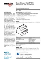
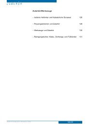
The electrical connection has to be effected according to Figure 1, if the<br />
heater is connected directly to the thermostats. The power supply of the<br />
thermostat has to be protected by a fuse (16 A). The terminal 5 can be<br />
used as signal “temperature achieved”.<br />
Figure 1<br />
Max<br />
C16 A<br />
30mA<br />
Heating system<br />
If the thermostat is used as a surface thermostat, a safe contact between<br />
the sensor and the surface is necessary.<br />
Potential free output:<br />
The switching contact can be used potential-free, e.g. for selecting contactors<br />
or other positioning elements (terminals 2, 3 and 5)<br />
5
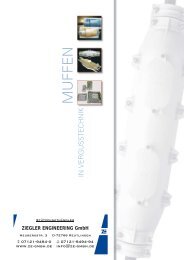
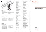
Figure 2<br />
6<br />
90<br />
122<br />
<strong>10</strong>6<br />
82<br />
120
3. Function and operation<br />
After removing the cover, the desired temperature can be adjusted on the<br />
adjustment knob. The thermostat switches from terminal 3 to terminal 5 if<br />
the adjusted temperature value is achieved. After adjusting the desired<br />
temperature, the cover has to be mounted again to meet the protective<br />
system IP 65.<br />
4. Survey and technical data<br />
Temperature range Sensor temperature Max. Order reference<br />
0 up to +50°C +60°C T-M-<strong>10</strong>-S/0+50C<br />
0 up to +200°C +230°C T-M-<strong>10</strong>-S/0+200C<br />
+50 up to +300°C +345°C T-M-<strong>10</strong>-S/+50+300C<br />
Technical data:<br />
Voltage: 230 V AC<br />
Breaking capacity: 16 A / 250 V (contact potential-free)<br />
Frequency: 50 / 60 Hz<br />
Nominal current: 16 A<br />
Protective class: I<br />
Environmental protection: IP 65<br />
Working temperature: –20 up to +80°C<br />
Hysteresis: 2.5% of temperature range<br />
Accuracy: ±1,5% of setpoint for temperature<br />
setting in upper third of range<br />
(measured at 22°C)<br />
Enclosure: Polyester<br />
Glands: 1 x M20 + 1 x M25 incl. reducer M25/M20<br />
Dimensions: 122 x 120 x 90 mm<br />
Weight: 1.2 kg<br />
Length of capillary tube: appr. 2 m<br />
Material of capillary tube: V4A Stainless Steel<br />
7
5. Accessories<br />
The following mounting brackets are available for<br />
T-M-<strong>10</strong>-S/<strong>+x+y</strong>: SB-<strong>10</strong>0, SB-<strong>10</strong>1, SB-1<strong>10</strong>, SB-111<br />
8
Kapillarrohrthermostat für den Nicht-Ex-Bereich<br />
Der Thermostat T-M-<strong>10</strong>-S/<strong>+x+y</strong> ist zur Temperaturregelung elektrischer<br />
Beheizungen an Teilen und in Anlagen des industriellen und gewerblichen<br />
Bereichs einsetzbar. Er eignet sich für einfache Anforderungen wie<br />
Frostschutz und Konstanthaltung von Produkttemperaturen in verschiedenen<br />
Temperaturbereichen. Aufgrund seiner hohen Schaltleistung von 3500<br />
VA ist er auch zum direkten Schalten der Heizung bis zu dieser Leistung<br />
geeignet. Der direkte Anschluß des Heizbandes oder der Heizleitung ist<br />
möglich.<br />
Eingebaut in einem IP 65 Gehäuse aus Polyester ist er witterungsbeständig<br />
und kann als Luft- oder Anlegethermostat eingesetzt werden.<br />
1. Sicherheitsbestimmungen<br />
Sicherheitstechnisch entspricht dieses Regelgerät VDE 0631 und<br />
VDE 0<strong>10</strong>0. Um diesen Zustand zu erhalten, sind folgende Hinweise und<br />
Warnvermerke zu beachten:<br />
Achtung!<br />
Das Gerät ist ein elektrisches Betriebsmittel. Daher darf die Bedienung<br />
nur durch eingewiesenes Personal erfolgen.<br />
Wartung, Anschluß und Repartur sind von geschultem, fach- und<br />
sachkundigem Personal durchzuführen.<br />
Öffnen des Gerätes:<br />
Vor dem Öffnen der Abdeckung oder Entfernen von Teilen mit Werkzeug,<br />
muß das Gerät von allen Spannungsquellen getrennt sein!<br />
Fehler und außergewöhnliche Beanspruchungen:<br />
Wenn anzunehmen ist, daß ein gefahrloser Betrieb nicht mehr möglich ist,<br />
so muß das Gerät außer Betrieb gesetzt und gegen unabsichtliche<br />
Inbetriebnahme gesichert werden.<br />
Dieser Fall tritt ein<br />
• wenn das Gerät sichtbare Beschädigungen aufweist,<br />
• wenn das Gerät nicht mehr arbeitet,<br />
• nach Überbeanspruch jeglicher Art, die die zulässigen Grenzen überschreitet<br />
(z.B. Lagerung, Transport)<br />
9
Erdung:<br />
Der Schutzleiter der Heizung wird über die Klemmleiste des Reglers zum<br />
Verbraucher geschleift. Um diese Schutsmaßnahme nicht unwirksam zu<br />
machen, dürfen keine Netz- oder Verbindungsleitungen ohne Schutzleiter<br />
angeschlossen werden.<br />
Netzspannung:<br />
Vor dem Netzanschluß ist die Übereinstimmung der Netzspannung mit der<br />
des Gerätes zu überprüfen.<br />
Kapillarrohre:<br />
Der Kapillarrohrfühler und die Kapillare sind vor Beschädigung zu<br />
schützen, da bei Druckabfall im Kapillarsystem der Regler einschaltet. Eine<br />
Verformung des Kapillarrohrfühlers ist zu vermeiden. Bei verformten<br />
Kapillarrohr ist eine genaue Temperaturmessung nicht mehr gewährleistet.<br />
2. Elektrischer Anschluß und Montage<br />
Nach Abnehmen des Gehäusedeckels kann das Gerät mit 4 Schrauben -<br />
sowohl senkrecht als auch waagerecht - befestigt werden. Der Abstand der<br />
Befestigungsbohrungen beträgt 82 mm x <strong>10</strong>6 mm.<br />
Der elektrische Anscluß wird nach Bild 1 vorgenommen, wenn die Heizung<br />
direkt über den Thermostat geschaltet werden soll. Die Einspeisung des<br />
Thermostaten ist mit 16 A abzusichern. Klemme 5 kann als Meldung<br />
“Temperatur erreicht” verwendet werden.<br />
Bild 1<br />
<strong>10</strong><br />
Max<br />
C16 A<br />
30mA<br />
Elektrische Heating system Beheizung
Bild 2<br />
90<br />
122<br />
<strong>10</strong>6<br />
82<br />
120<br />
11
Wird der Thermostat als Oberflächenthermostat eingesetzt, so ist auf einen<br />
sicheren Kontakt des Fühlers zur Oberfläche zu achten.<br />
Potentialfreier Ausgang:<br />
Der Schaltkontakt kann potentialfrei verwendet werden z.B. zur<br />
Ansteuerung von Schützen oder anderen Stellgliedern<br />
(Klemmen 2, 3 und 5).<br />
3. Funktion und Bedienung<br />
Nach Öffnen des Gehäusedeckels kann die gewünschte Temperatur am<br />
Stellknopf eingestellt werden. Der Thermostat schaltet von Klemme 3 auf<br />
Klemme 5 um, wenn der eingestellte Temperaturwert überschrittten wird.<br />
Nach Einstellung der gewünschten Temperatur ist der Gehäusedeckel<br />
wieder zu montieren, da nur so die Schutzart IP 65 gewährleistet ist.<br />
Der Thermostat arbeitet nach dem Prinzip der Flüssigkeitausdehnung.<br />
Ändert sich die Temperatur im flüssigkeitsgefüllten Fühlersystem (bestehend<br />
aus Fühler, Kapillarleitung und Membrane) so ändert sich das<br />
Volumen. Der daraus resultierende Hub der Membrane betätigt über Hebel<br />
den Schalter.<br />
4. Typenübersicht und technische Daten<br />
Temperaturbereich Fühlertemperature Max. Best.-Nr.<br />
0 bis +50°C +60°C T-M-<strong>10</strong>-S/0+50C<br />
0 bis +200°C +230°C T-M-<strong>10</strong>-S/0+200C<br />
+50 bis +300°C +345°C T-M-<strong>10</strong>-S/+50+300C<br />
Technische Daten:<br />
Betriebsspannung: ±230 V AC<br />
Schaltleistung: 16 A / 250 V (Kontakt potentialfrei)<br />
Netzfrequenz: 50 / 60 Hz<br />
Nennstrom: 16 A<br />
Schutzklasse: I<br />
Schutzart: IP 65<br />
Betriebstemperatur: –20 bis +80°C<br />
Schaltdifferenz: 2.5% vom Temperaturbereich<br />
12
Gehäuse: Polyester<br />
Verschraubungen: 1 x M20 + 1 x M25 incl. Adapter M25/M20<br />
Maße: 122 x 120 x 90 mm<br />
Gewich: 1.2 kg<br />
Kapillarrohrlänge: ca. 2 m<br />
Kapillarrohrmaterial: V4A<br />
5. Zubehör<br />
Zum Thermostaten ist folgendes Montagezubehör lieferbar:<br />
T-M-<strong>10</strong>-S/<strong>+x+y</strong>: SB-<strong>10</strong>0, SB-<strong>10</strong>1, SB-1<strong>10</strong>, SB-111<br />
13
Thermostat de surface pour zones non explosibles<br />
Le thermostat T-M-<strong>10</strong>-S/<strong>+x+y</strong> a été conçu pour contrôler la température<br />
des résistances de traçage électrique sur les sites industriels.<br />
Il s’utilise pour des applications simples de mise hors gel ou de maintien<br />
en température. Sa puissance de coupure élevée de 3700 VA permet de<br />
connecter directement le ruban chauffant. Rubans et câbles chauffants<br />
peuvent se brancher directement sur le thermostat. Équipé d’une sonde à<br />
bulbe et capillaire, il s’utilise pour mesurer la température de l’air ambiant<br />
ou de l’élément sur lequel il est fixé. Il est logé dans un boîtier polyester<br />
étanche IP 65.<br />
1. Précautions d’emploi<br />
Cet appareil est conforme aux normes VDE 0631 et VDE 0<strong>10</strong>0. Respecter<br />
impérativement les règles suivantes :<br />
Attention !<br />
Ce thermostat est un appareil électrique.<br />
Seul un personnel qualifié est habilité à l’installer, l’entretenir et le<br />
réparer.<br />
Ouverture du thermostat :<br />
Isoler le thermostat de toute source de tension avant de l’ouvrir.<br />
Pannes et dommages mécaniques :<br />
Si le thermostat ne répond plus aux normes de sécurité, le débrancher et<br />
interdire son utilisation accidentelle.<br />
Cas d’espèces :<br />
• un thermostat qui présente des dégâts visibles consécutifs au stockage<br />
ou au transport<br />
• un thermostat en panne<br />
Mise à la terre :<br />
Le câble de mise à la terre du circuit de traçage est branché au bornier du<br />
thermostat. Le thermostat doit donc également être mis à la terre.<br />
Tension :<br />
Avant de brancher l’alimentation électrique du thermostat, s’assurer que sa<br />
tension correspond à celle du réseau.<br />
14
Sonde :<br />
Il convient de protéger la sonde, bulbe et capillaire, de dégâts éventuels.<br />
Une baisse de pression dans le système capillaire déclenche la mise en<br />
marche du thermostat. La mesure correcte des températures n’est pas<br />
garantie si la sonde est endommagée.<br />
2. Montage et raccordement électrique<br />
Enlever le couvercle et attacher le thermostat verticalement ou horizontalement<br />
au moyen des quatre vis. Les trous prévus pour les vis sont espacés<br />
de 80 mm et 160 mm.<br />
Lorsque la résistance chauffante est branchée directement sur le thermostat,<br />
le raccordement électrique doit être conforme à la Figure 1.<br />
L’alimentation du thermostat doit être protégée par un fusible (16A).<br />
La borne 5 peut être utilisée comme signal « température atteinte ».<br />
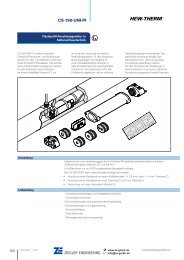
Figure 1<br />
Max<br />
C16 A<br />
30mA<br />
Système Heating de system traçage<br />
15
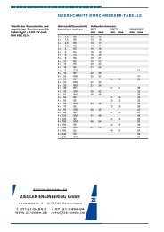
Figure 2<br />
16<br />
90<br />
122<br />
<strong>10</strong>6<br />
82<br />
120
Si le thermostat est utilisé comme thermostat de contrôle, il est nécessaire<br />
d’établir un contact franc entre la sonde et la surface à mesurer.<br />
Sorties hors tension:<br />
Le commutateur peut être utilisé hors tension, par exemple pour sélectionner<br />
des contacteurs ou d’autres éléments positionnables (bornes 2, 3 et 5)<br />
3. Fonctions et utilisation<br />
Pour sélectionner la température souhaitée, ouvrir le boîtier et tourner le<br />
bouton de réglage. Le thermostat commute de la borne 3 à la borne 5<br />
lorsque la température sélectionnée est atteinte. Lorsque la température<br />
souhaitée est paramétrée, refermer le boîtier de manière étanché, conformément<br />
à sa classification IP 65.<br />
4. Spécifications et caractéristiques techniques<br />
Plage de températures Température de sonde Max. Référence de commande<br />
0 à +50 °C +60 °C T-M-<strong>10</strong>-S/0+50C<br />
0 à +200 °C +230 °C T-M-<strong>10</strong>-S/0+200C<br />
+50 à +300 °C +345 °C T-M-<strong>10</strong>-S/+50+300C<br />
Caractéristiques techniques :<br />
Tension : 230 VCA<br />
Pouvoir de coupure : 16 A / 250 V (contact hors tension)<br />
Fréquence : 50 / 60 Hz<br />
Ampérage : 16 A<br />
Classe de protection : I<br />
Indice de protection : IP 65<br />
Température de service : –20 à +80 °C<br />
Hystérésis : 2,5% de la plage de température<br />
Précision : ±1,5% de la température prédéterminée,<br />
dans le tiers supérieur de la plage<br />
(mesuré à 22 °C)<br />
17
Boîtier : Polyester<br />
Presse-étoupe : 1 x M20 + 1 x M25 avec réducteur M25/M20<br />
Dimensions : 122 x 120 x 90 mm<br />
Poids : 1,2 kg<br />
Longueur du capillaire : environ 2 m<br />
Matériau du capillaire : Acier inoxydable V4A<br />
5. Accessoires<br />
Supports de fixation pour T-M-<strong>10</strong>-S/<strong>+x+y</strong> : SB-<strong>10</strong>0, SB-<strong>10</strong>1, SB-1<strong>10</strong>,<br />
SB-111<br />
18
België / Belgique<br />
Tyco <strong>Thermal</strong> Controls<br />
Staatsbaan 4A<br />
32<strong>10</strong> Lubbeek<br />
Tel. (016) 213 511<br />
Fax (016) 213 6<strong>10</strong><br />
Çeská Republika<br />
Raychem HTS s.r.o.<br />
Novodvorská 82<br />
14200 Praha 4<br />
Tel. 241 009 215<br />
Fax 241 009 219<br />
Danmark<br />
Tyco <strong>Thermal</strong> Controls Nordic AB<br />
Stationsvägen 4<br />
S-430 63 Hindås<br />
Tel. 70 11 04 00<br />
Fax 70 11 04 01<br />
Deutschland<br />
Tyco <strong>Thermal</strong> Controls GmbH<br />
Kölner Straße 46<br />
57555 Mudersbach<br />
Tel. 0800 1818205<br />
Fax 0800 1818204<br />
España<br />
Tracelec<br />
C/Josep V. Foix, <strong>10</strong><br />
Apdo. 1326-43080<br />
43007 Tarragona<br />
Tel. (34) 977 290 039<br />
Fax (34) 977 290 032<br />
France<br />
Tyco <strong>Thermal</strong> Controls SA<br />
B.P. 90738<br />
95004 Cergy-Pontoise Cedex<br />
Tél. 0800 906045<br />
Fax 0800 906003<br />
Hrvatska<br />
ELGRI d.o.o.<br />
S. Mihalica 2<br />
<strong>10</strong>000 Zagreb<br />
Tel. (1) 6050188<br />
Fax (1) 6050187<br />
Italia<br />
Tyco Electronics Raychem SPA<br />
Centro Direzionale Milanofiori<br />
Palazzo E5<br />
20090 Assago, Milano<br />
Tel. (02) 57 57 61<br />
Fax (02) 57 57 62 01<br />
Magyarország<br />
Szarka Ignác<br />
Maroshévísz u. 8<br />
1173 Budapest<br />
Tel. (1) 253 76 17<br />
Fax (1) 253 76 18<br />
Nederland<br />
Tyco <strong>Thermal</strong> Controls b.v.<br />
Van Heuven Goedhartlaan 121<br />
1181 KK Amstelveen<br />
Tel. 0800 0224978<br />
Fax 0800 0224993<br />
Norge<br />
Tyco <strong>Thermal</strong> Controls Norway AS<br />
Malerhaugveien 25<br />
Postboks 6076 - Etterstad<br />
0602 Oslo<br />
Tel. 66 81 79 90<br />
Fax 66 80 83 92<br />
Österreich<br />
Tyco <strong>Thermal</strong> Controls N.V.<br />
Lubbeek<br />
Office Wien<br />
Brown-Boveri Strasse 6/14<br />
2351 Wiener Neudorf<br />
Tel. (0 22 36) 86 00 77<br />
Fax (0 22 36) 86 00 77-5<br />
Polska<br />
Raychem Polska Sp. z o.o.<br />
Tyco <strong>Thermal</strong> Controls<br />
ul. Farbiarska 69 C<br />
02-862 Warszawa<br />
Tel. (022) 33 12 950<br />
Fax (022) 33 12 951<br />
Schweiz / Suisse<br />
Tyco <strong>Thermal</strong> Controls N.V.<br />
Office Baar<br />
Haldenstrasse 5<br />
Postfach 2724<br />
6342 Baar<br />
Tel. (041) 766 30 80<br />
Fax (041) 766 30 81<br />
Suomi<br />
Tyco <strong>Thermal</strong> Controls Nordic AB<br />
Stationsvägen 4<br />
S-430 63 Hindås<br />
Puh. 0800 116799<br />
Telekopio 0800 118674<br />
Sverige<br />
Tyco <strong>Thermal</strong> Controls Nordic AB<br />
Kanalvägen 3 A<br />
S-194 61 Upplands Väsby<br />
Tel. 08-590 094 60<br />
Fax 08-590 925 70<br />
United Kingdom<br />
Tyco <strong>Thermal</strong> Controls (UK) Ltd<br />
3 Rutherford Road,<br />
Stephenson Industrial Estate<br />
Washington, Tyne & Wear<br />
NE37 3HX<br />
Tel. 0800 969013<br />
Fax: 0800 968624<br />
ROSSIÅ i drugie strany SNG<br />
RAJXEM<br />
125315, g. Moskva<br />
Leningradskij prospekt, dom 72,<br />
ofis 807<br />
Tel.: (095) 7211888<br />
Faks: (095) 7211891<br />
www.tycothermal.com<br />
© 2001 Tyco <strong>Thermal</strong> Controls INSTALL-067 Rev.2 06/05 Printed in Belgium on recycled paper.