POS-124-PDP
POS-124-PDP
POS-124-PDP

Create successful ePaper yourself
Turn your PDF publications into a flip-book with our unique Google optimized e-Paper software.
W.E.ST. Elektronik GmbH<br />
Technical Documentation<br />
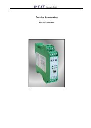
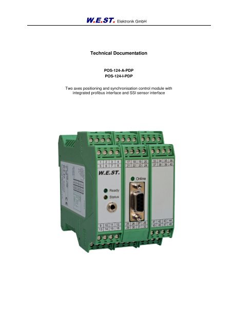
<strong>POS</strong>-<strong>124</strong>-A-<strong>PDP</strong><br />
<strong>POS</strong>-<strong>124</strong>-I-<strong>PDP</strong><br />
Two axes positioning and synchronisation control module with<br />
integrated profibus interface and SSI sensor interface
W.E.ST. Elektronik GmbH<br />
CONTENTS<br />
1 General Information ............................................................................................................................................. 4<br />
1.1 Order number .............................................................................................................................................. 4<br />
1.2 Scope of supply ........................................................................................................................................... 4<br />
1.3 Accessories ................................................................................................................................................. 4<br />
1.4 Symbols used .............................................................................................................................................. 5<br />
1.5 Using this documentation ............................................................................................................................ 5<br />
1.6 Legal notice ................................................................................................................................................. 5<br />
1.7 Safety instructions ....................................................................................................................................... 6<br />
2 Characteristics ..................................................................................................................................................... 7<br />
2.1 Device description ....................................................................................................................................... 8<br />
3 Use and application ............................................................................................................................................. 9<br />
3.1 Installation instructions ................................................................................................................................ 9<br />
3.2 Typical system structure ............................................................................................................................ 10<br />
3.3 Method of operation ................................................................................................................................... 10<br />
3.4 Commissioning .......................................................................................................................................... 12<br />
4 Technical description ......................................................................................................................................... 13<br />
4.1 Input and output signals ............................................................................................................................. 13<br />
4.2 LED definitions ........................................................................................................................................... 14<br />
4.3 Circuit diagram ........................................................................................................................................... 15<br />
4.4 Typical cabling ........................................................................................................................................... 16<br />
4.5 Connection examples ................................................................................................................................ 16<br />
4.6 Technical data ........................................................................................................................................... 17<br />
5 Parameters ........................................................................................................................................................ 18<br />
5.1 Parameter overview ................................................................................................................................... 18<br />
5.2 Parameter description ................................................................................................................................ 20<br />
5.2.1 LG (Changing the language for the help texts) ................................................................................. 20<br />
5.2.2 <strong>PDP</strong>ADR (Profibus adress) ............................................................................................................... 20<br />
5.2.3 MODE (Switching between parameter groups) ................................................................................. 20<br />
5.2.4 SENS (Module monitoring) ............................................................................................................... 21<br />
5.2.5 STROKE1 /STROKE2 (Full stroke) ................................................................................................... 21<br />
5.2.6 VRAMP1 /VRAMP2 (Ramp time for external speed demand) .......................................................... 21<br />
5.2.7 VMODE1 / VMODE2 (Switching over the control mode)................................................................... 22<br />
5.2.8 VMAX1 / VMAX2 (Maximum speed in NC Mode) ............................................................................. 22<br />
5.2.9 POL1 / POL2 (Output polarity) .......................................................................................................... 23<br />
5.2.10 EOUT1 / EOUT2 (Output signal in case of error) .............................................................................. 23<br />
5.2.11 INPX (Sensor type define) ................................................................................................................ 24<br />
5.2.12 SSI:OFFSET (Sensor offset) ............................................................................................................. 24<br />
5.2.13 SSI:POL (Direction of the sensor signal) ........................................................................................... 24<br />
5.2.14 SSI:RES (Signal resolution) .............................................................................................................. 25<br />
5.2.15 SSI:BITS (Number of bits) ................................................................................................................. 25<br />
5.2.16 SSI:CODE (Signal coding) ................................................................................................................ 25<br />
5.2.17 AIN (Analogue input scaling) ............................................................................................................. 26<br />
5.2.18 A1 / A2 (Acceleration time) ............................................................................................................... 27<br />
5.2.19 D1 / D2 (Deceleration / braking distance) ......................................................................................... 27<br />
5.2.20 V01 / V02 (Loop gain setting) ............................................................................................................. 28<br />
5.2.21 CTRL1 / CTRL2 (Deceleration function characteristic) ..................................................................... 29<br />
5.2.22 GL: P (gain of the synchronization in SDD mode) ............................................................................. 30<br />
5.2.23 GL: V0 (gain of the synchronization in NC mode) ............................................................................. 30<br />
5.2.24 GL:T1 (Time constant of the synchronisation control) ....................................................................... 30<br />
5.2.25 GL:E (Window for the synchronization error) .................................................................................... 30<br />
Page 2 of 45 <strong>POS</strong>-<strong>124</strong>-*-<strong>PDP</strong>-1121 13.02.2013
W.E.ST. Elektronik GmbH<br />
5.2.26 HAND1 / HAND2 (Manual speed) ..................................................................................................... 31<br />
5.2.27 MIN / MIN2 (Overlap compensation) ................................................................................................. 32<br />
5.2.28 MAX1 / MAX2 (Limitation) ................................................................................................................. 32<br />
5.2.29 TRIGGER (Response threshold for the MIN parameter) ................................................................... 32<br />
5.2.30 OFFSET1 / OFFSET2 (Zero correction) ............................................................................................ 33<br />
5.2.31 IN<strong>POS</strong>:S1 / IN<strong>POS</strong>:S2 (In position window) ...................................................................................... 33<br />
5.2.32 IN<strong>POS</strong>:D1 / IN<strong>POS</strong>:D2 (following error window) ............................................................................... 33<br />
5.2.33 PROCESS DATA (Monitoring) .......................................................................................................... 34<br />
6 Appendix ............................................................................................................................................................ 35<br />
6.1 Failure monitoring ...................................................................................................................................... 35<br />
6.2 Troubleshooting ......................................................................................................................................... 35<br />
6.3 Description of the command structure ........................................................................................................ 37<br />
7 Profibus DP interface ......................................................................................................................................... 38<br />
7.1 Profibus functions....................................................................................................................................... 38<br />
7.2 Installation .................................................................................................................................................. 38<br />
7.3 GSD Configuration File .............................................................................................................................. 38<br />
7.4 Description Profibus DP interface .............................................................................................................. 39<br />
7.5 Commands via PROFIBUS ........................................................................................................................ 40<br />
7.5.1 Command map .................................................................................................................................. 40<br />
7.5.2 Definition of the control bits: .............................................................................................................. 41<br />
7.6 DATA send to PROFIBUS ......................................................................................................................... 42<br />
7.6.1 Feedback map ................................................................................................................................... 42<br />
7.6.2 Definition of the status bits: ............................................................................................................... 43<br />
8 Notes.................................................................................................................................................................. 44<br />
Page 3 of 45 <strong>POS</strong>-<strong>124</strong>-*-<strong>PDP</strong>-1121 13.02.2013
1 General Information<br />
1.1 Order number<br />
W.E.ST. Elektronik GmbH<br />
<strong>POS</strong>-<strong>124</strong>-A-<strong>PDP</strong>-1121 1 triple stage module with digital SSI-interface with analogue ±10 V<br />
differential output, housing width 67,5 mm<br />
<strong>POS</strong>-<strong>124</strong>-I-<strong>PDP</strong>-1121 triple stage module with digital SSI-interface with analogue 4… 20 mA<br />
output, housing width 67,5 mm<br />
Alternative products:<br />
<strong>POS</strong>-<strong>124</strong>-A-<strong>PDP</strong>-S1-1121 double stage module without digital SSI-interface with analogue ±10 V<br />
differential output, 45 mm housing width<br />
<strong>POS</strong>-<strong>124</strong>-I-<strong>PDP</strong>-S1-1121 double stage module without digital SSI-interface with analogue<br />
4… 20 mA output, 45 mm housing width<br />
1.2 Scope of supply<br />
The scope of supply includes the module including the terminal blocks which are a part of the housing.<br />
The Profibus plug, interface cables and further parts which may be required should be ordered separately.<br />
This documentation can be downloaded as a PDF file from www.w-e-st.de.<br />
1.3 Accessories<br />
RS232-SO - Programming cable with RS232 interface<br />
USB-SO - Programming cable with USB interface<br />
WPC-300 - Start-Up-Tool (download: www.w-e-st.de/produkte/software)<br />
<strong>PDP</strong>-Plug - Profibus connector with switchable terminating resistors<br />
1 The number of the version consists of the hardware-version (first two digits) and the software-version (second two<br />
digits). Because of the development of the products these numbers can vary. They are not strictly necessary for the<br />
order. We will always deliver the newest version.<br />
Page 4 of 45 <strong>POS</strong>-<strong>124</strong>-*-<strong>PDP</strong>-1121 13.02.2013
1.4 Symbols used<br />
General information<br />
Safety-related information<br />
1.5 Using this documentation<br />
Structure of the documentation:<br />
W.E.ST. Elektronik GmbH<br />
The standard product is descibed up to chapter 6. The extensions like POWER STAGE or<br />
SSI-INTERFACE are described in the chapters ADDITIONAL INFORMATION.<br />
1.6 Legal notice<br />
W.E.St. Elektronik GmbH<br />
Gewerbering 31<br />
D-41372 Niederkrüchten<br />
Tel.: +49 (0)2163 577355-0<br />
Fax.: +49 (0)2163 577355 -11<br />
Homepage: www.w-e-st.de or www.west-electronics.com<br />
EMAIL: info@w-e-st.de<br />
Date: 13.02.2013<br />
The data and characteristics described herein serve only to describe the product. The user is required to<br />
evaluate this data and to check suitability for the particular application. General suitability cannot be inferred<br />
from this document. We reserve the right to make technical modifications due to further development<br />
of the product described in this manual. The technical information and dimensions are non-binding.<br />
No claims may be made based on them.<br />
This document is copyright.<br />
Page 5 of 45 <strong>POS</strong>-<strong>124</strong>-*-<strong>PDP</strong>-1121 13.02.2013
1.7 Safety instructions<br />
W.E.ST. Elektronik GmbH<br />
Please read this document and the safety instructions carefully. This document will help to define the<br />
product area of application and to put it into operation. Additional documents (WPC-300 for the start-up<br />
software) and knowledge of the application should be taken into account or be available.<br />
General regulations and laws (depending on the country: e.g. accident prevention and environmental protection)<br />
must be complied with.<br />
These modules are designed for hydraulic applications in open or closed-loop control circuits.<br />
Uncontrolled movements can be caused by device defects (in the hydraulic module<br />
or the components), application errors and electrical faults. Work on the drive or the electronics<br />
must only be carried out whilst the equipment is switched off and not under pressure.<br />
This handbook describes the functions and the electrical connections for this electronic<br />
assembly. All technical documents which pertain to the system must be complied with<br />
when commissioning.<br />
This device may only be connected and put into operation by trained specialist staff. The<br />
instruction manual must be read with care. The installation instructions and the commissioning<br />
instructions must be followed. Guarantee and liability claims are invalid if the instructions<br />
are not complied with and/or in case of incorrect installation or inappropriate<br />
use.<br />
CAUTION!<br />
All electronic modules are manufactured to a high quality. Malfunctions due to the failure<br />
of components cannot, however, be excluded. Despite extensive testing the same also<br />
applies for the software. If these devices are deployed in safety-relevant applications,<br />
suitable external measures must be taken to guarantee the necessary safety. The same<br />
applies for faults which affect safety. No liability can be assumed for possible damage.<br />
Further instructions<br />
• The module may only be operated in compliance with the national EMC regulations. It<br />
is the user’s responsibility to adhere to these regulations.<br />
• The device is only intended for use in the commercial sector.<br />
• When not in use the module must be protected from the effects of the weather, contamination<br />
and mechanical damage.<br />
• The module may not be used in an explosive environment.<br />
• To ensure adequate cooling the ventilation slots must not be covered.<br />
• The device must be disposed of in accordance with national statutory provisions.<br />
Page 6 of 45 <strong>POS</strong>-<strong>124</strong>-*-<strong>PDP</strong>-1121 13.02.2013
2 Characteristics<br />
W.E.ST. Elektronik GmbH<br />
This electronic module has been developed for controlling hydraulic positioning drives.<br />
Both axes are controlled complete autonomous via the Profibus. Optionally an interconnection to a two<br />
axes synchronised system is intended.<br />
The differential outputs are covered for activation of constant valves with integrated or external<br />
electronics (differential input). Intended is this module for the connection of analogue way sensors 0...10V<br />
or 4...20mA (scalable) or digital SSI sensor interfaces.<br />
The internal control signals operating states and error conditions via Profibus to the higher-level control.<br />
The operation is signaled by a switch output.<br />
Typical applications: Positioning control or synchronization control with hydraulic axes.<br />
Features<br />
• Two independent positioning axes<br />
• Can be combined for synchronization controls<br />
• Command position parameter, actual value response, on loop control byte and status byte via<br />
fieldbus Profibus DP<br />
• Principle of stroke-dependent deceleration for the shortest positioning time or NC profile gen-<br />
erator for constant speed<br />
• Analogue or digital (SSI) actual value registration for both axes<br />
• Superimposed synchronization controller as PT1 actuator<br />
• Usable with zero lapped control valves<br />
• Fault diagnosis and extended function checking<br />
• Simplified parameterization with WPC-300 software version 3.2<br />
Page 7 of 45 <strong>POS</strong>-<strong>124</strong>-*-<strong>PDP</strong>-1121 13.02.2013
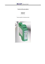
2.1 Device description<br />
D-outputs<br />
Ready<br />
24 V<br />
0 V<br />
Enable<br />
D-inputs<br />
99,0000 mm<br />
1<br />
2<br />
3<br />
4<br />
5<br />
6<br />
7<br />
8<br />
9<br />
10<br />
11<br />
12<br />
13<br />
14<br />
15<br />
16<br />
Made in Germany<br />
Date: Add.:<br />
ID:<br />
V:<br />
Analogue<br />
GND<br />
GND<br />
Pos. 1<br />
Pos. 2<br />
W.E.ST. Elektronik<br />
A Differential<br />
B output<br />
D-41372 Niederkrüchten<br />
Homepage: http://www.w-e-st.de<br />
Typenschild und Anschlussbelegung<br />
Type plate and terminal pin assignment<br />
W.E.ST. Elektronik GmbH<br />
LEDs<br />
RS232<br />
Interface<br />
1 2 3 4 17 18 19 20 33 34 35 36<br />
5 6 7 8 21 22 23 24 37 38 39 40<br />
W.E.ST.<br />
Page 8 of 45 <strong>POS</strong>-<strong>124</strong>-*-<strong>PDP</strong>-1121 13.02.2013<br />
Ready<br />
Status<br />
Online<br />
Profibus<br />
9pol SUBD<br />
9 10 11 12 25 26 27 28 41 42 43 44<br />
13 14 15 16 29 30 31 32 45 46 47 48<br />
67,5000 mm<br />
121,0000 mm<br />
114,0000 mm<br />
Klemmblöcke (steckbar)<br />
Terminals (removable)<br />
PROFIBUS Buchse<br />
PROFIBUS connector
3 Use and application<br />
3.1 Installation instructions<br />
W.E.ST. Elektronik GmbH<br />
• This module is designed for installation in a shielded EMC housing (control cabinet). All cables<br />
which lead outside must be screened; complete screening is required. It is also a requirement<br />
that no strong electro-magnetic interference sources are installed nearby when using our control<br />
and regulation modules.<br />
• Typical installation location: 24V control signal area (close to PLC)<br />
The devices must be arranged in the control cabinet so that the power section and the signal section<br />
are separate from each other.<br />
Experience shows that the installation space close to the PLC (24 V area) is most suitable. All<br />
digital and analogue inputs and outputs are fitted with filters and surge protection in the device.<br />
• The module should be installed and wired in accordance with the documentation bearing in mind<br />
EMC principles. If other consumers are operated with the same power supply, a star- connected<br />
ground wiring scheme is recommended. The following points must be observed when wiring:<br />
• The signal cables must be laid separately from power cables.<br />
• Analogue signal cables must be shielded.<br />
• All other cables must be screened if there are powerful interference sources (frequency<br />
converters, power contactors) and cable lengths > 3m. Inexpensive SMD ferrites<br />
can be used with high-frequency radiation.<br />
• The screening should be connected to PE (PE terminal) as close to the module as<br />
possible. The local requirements for screening must be taken into account in all cases.<br />
The screening should be connected to at both ends. Equipotential bonding must be<br />
provided where there are differences between the connected electrical components.<br />
• With longer lengths of cable (>10 m) the diameters and screening measures should<br />
be checked by specialists (e.g. for possible interference, noise sources and voltage<br />
drop). Particular care is required with cables of over 40 m in length – the manufacturer<br />
should be consulted if necessary.<br />
• A low-resistance connection between PE and the mounting rail should be provided. Transient interference<br />
is transmitted from the module directly to the mounting rail and from there to the local<br />
earth.<br />
• Power should be supplied by a regulated power supply unit (typically a PELV system complying<br />
with IEC364-4-4, secure low voltage). The low internal resistance of regulated power supplies<br />
gives better interference voltage dissipation, which improves the signal quality of high-resolution<br />
sensors in particular. Switched inductances (relays and valve coils connected to the same power<br />
supply) must always be provided with appropriate overvoltage protection directly at the coil.<br />
Page 9 of 45 <strong>POS</strong>-<strong>124</strong>-*-<strong>PDP</strong>-1121 13.02.2013
3.2 Typical system structure<br />
W.E.ST. Elektronik GmbH<br />
This minimal system consists of the following components:<br />
(*1) proportional valve<br />
(*2) hydraulic cylinder<br />
(*3) position sensor<br />
(*4) <strong>POS</strong>-<strong>124</strong>-<strong>PDP</strong> control module<br />
(*5) interface to PLC with analogue and digital signals<br />
3.3 Method of operation<br />
This control module supports simple point-to-point positioning with hydraulic drives. The system works<br />
based on the principle of stroke-dependent deceleration, i.e. the control gain (deceleration stroke) is set<br />
via parameters D:A and D:B. Alternatively the loop gain will be used in NC mode.<br />
The deceleration characteristics can be set linearly (LIN) or approximately quadratically (SQRT1) via the<br />
CTRL parameter. For normal proportional valves SQRT1 is the input setting.<br />
For control valves with a linear flow curve it depends on the application. If LIN is selected for these valves<br />
a significantly shorter deceleration distance can often be set (D:A and D:B).<br />
Page 10 of 45 <strong>POS</strong>-<strong>124</strong>-*-<strong>PDP</strong>-1121 13.02.2013
W.E.ST. Elektronik GmbH<br />
Positioning sequence:<br />
The positioning is controlled via Profibus. After releasing (ENABLE input), the command<br />
position is set to the actual position of the sensor and the axis stays in closed loop position control<br />
mode. The READY output indicates that the system is generally ready for operation. When setting the<br />
START-signal, the preset command value will be taken over. The axis immediately will drive to this new<br />
command position and indicates reaching it by setting the InPos output.<br />
The InPos output stays active as long as the axis is within the preset InPos window and the START input<br />
is active. The driving velocity is forced by preset parameter, too.<br />
The axis can be driven in manual mode (START is off) using the control bits HAND+ or HAND-. The<br />
velocity is programmable. When the HAND signal is deactivated, the command position is set to the actual<br />
position and the system stays in closed loop position control mode.<br />
Setting the synchronous bit (GL) will synchronize both axes and the synchronization controller is overriding<br />
the position controller of axis 2. Axis 2 is now following axis 1 according to the master-slave-principle.<br />
Influences on positioning accuracy:<br />
The positioning accuracy is determined by the hydraulic and mechanical conditions. The right choice of<br />
valve is therefore a decisive factor. In addition, two mutually contradictory requirements (short position<br />
time and high accuracy) must be taken into account when designing the system.<br />
The electronic limitations lie mainly in the resolution of the analogue signals, although with our modules a<br />
resolution of < 0.01% only needs to be considered with long positions. In addition, the linearity of the individual<br />
signal points (PLC, sensor and control module) must be considered. The worst-case scenario is<br />
that a system-specific absolute fault occurs.<br />
The repeat accuracy is, however, not affected by this.<br />
V+<br />
V+<br />
volumetric flow P-A and B-T<br />
MAX:A<br />
A:A D:A<br />
D:B<br />
control direction<br />
driving out<br />
control direction<br />
driving in<br />
MAX:B<br />
Page 11 of 45 <strong>POS</strong>-<strong>124</strong>-*-<strong>PDP</strong>-1121 13.02.2013<br />
A:B
3.4 Commissioning<br />
Step Task<br />
W.E.ST. Elektronik GmbH<br />
Installation Install the device in accordance with the circuit diagram. Ensure it is wired correctly<br />
and that the signals are well shielded. The device must be installed in a metal<br />
protective housing (control cabinet or similar).<br />
Switching on for the first<br />
time<br />
Ensure that no unwanted movement is possible in the drive (e.g. switch off the<br />
hydraulics). Connect an ammeter and check the current consumed by the device.<br />
If it is higher than specified there is an error in the cabling. Switch the device off<br />
immediately and check the cabling.<br />
Setting up communication Once the power input is correct the PC (notebook) should be connected to the serial<br />
interface. Please see the WPC-300 program documentation for how to set up<br />
communication.<br />
Further commissioning and diagnosis are supported by the operating software.<br />
Pre-parameterisation Now set up the following parameters (with reference to the system design and circuit<br />
diagrams):<br />
The STROKE, <strong>POS</strong>ITION, SENSOR SETTING, POLARITY, ACCELERATION<br />
and DECELERATION.<br />
Pre-parameterisation is necessary to minimise the risk of uncontrolled movements.<br />
Parameterise specific settings for the control element (MIN for following error<br />
compensation and MAX for maximum velocity).<br />
Reduce the speed limitation to a value which is uncritical for the application.<br />
Control signals Check the control signal with a voltmeter. The control signals (PIN 15 to PIN16<br />
and PIN19 to PIN20) lies in the range of ± 10V. In the current state it should be<br />
0V. Alternatively, if current signals are used, approx. 0 mA should flow.<br />
CAUTION! This signal depends on the EOUT setting.<br />
Profibus communication Activate the profibus communication and check whether the right values and bits<br />
are send to the module.<br />
Switching on the hydraulics<br />
Activating ENABLE<br />
The hydraulics can now be switched on. Since the module is not yet generating a<br />
signal the drive should be at a standstill or drift slightly (leave its position at a slow<br />
speed).<br />
CAUTION! The drive can now leave its position and move to an end position at<br />
full speed. Take safety measures to prevent personal injury and damage.<br />
The drive is in the current position (with ENABLE the actual position is accepted<br />
as the required position). Should the drive move to an end position the polarity is<br />
probably wrong.<br />
Activating START With the start signal the demand value on the analogue demand value input is accepted<br />
and the axis moves to the predefined target position.<br />
If START is disabled the axis stops in the preset deceleration distance D:S.<br />
Manual (HAND) operation If START is disabled the axis can be moved manually with HAND+ or HAND- .<br />
After disabling the HAND signal, the axis stops in a controlled manner at the current<br />
position.<br />
Optimise controller Now optimise the controller parameters according to your application and your<br />
requirements.<br />
Page 12 of 45 <strong>POS</strong>-<strong>124</strong>-*-<strong>PDP</strong>-1121 13.02.2013
4 Technical description<br />
4.1 Input and output signals<br />
Connection Supply<br />
PIN 3, PIN 31<br />
and PIN 35<br />
PIN 4, PIN 32<br />
and PIN 36<br />
W.E.ST. Elektronik GmbH<br />
Power supply (see technical data)<br />
0 V (GND) connection.<br />
Caution, PIN 4 is connected internally to PIN 11 (and also possibly to PIN 12 depending on<br />
the model). These connections serve as a reference potential for the analogue sensor or<br />
demand value signals.<br />
Connection Analogue signals<br />
PIN 13 Analogue position actual value (X1), range 0… 100% corresponds to 0… 10V or 4… 20 mA<br />
PIN 14 Analogue position actual value (X2), range 0… 100% corresponds to 0… 10V or 4… 20 mA<br />
PIN 15 / 16 Analogue differential output for activation of the axis 1:<br />
-100...100% corresponds to -10...10V.<br />
PIN 19 / 20 Analogue differential output for activation of the axis 2:<br />
-100...100% corresponds to -10...10V.<br />
Connection SSI sensors<br />
PIN 37-40<br />
PIN 33, 34<br />
PIN 41-44<br />
PIN 47, 48<br />
Interface 1 to the SSI sensor. RS422 interface and power supply<br />
Interface 2 to the SSI sensor. RS422 interface and power supply<br />
Connection Digital inputs and outputs<br />
PIN 8<br />
Enable input:<br />
This digital input signal initializes the application. The signal will be approved in connection<br />
with the software enable the corresponding axis.<br />
PIN 2 Synchronous error output (only active in synchronous mode):<br />
ON: Slave axis within the error window (GL:E)<br />
PIN 1<br />
OFF: Slave axis outside the error window (GL:E)<br />
READY output:<br />
ON: The module is enabled; there are no discernable errors.<br />
OFF: Enable (PIN 8) is disabled or an error (sensor or internal error) has been detected.<br />
Page 13 of 45 <strong>POS</strong>-<strong>124</strong>-*-<strong>PDP</strong>-1121 13.02.2013
4.2 LED definitions<br />
W.E.ST. Elektronik GmbH<br />
LEDs Description of the LED function<br />
GREEN Identical to the READY output.<br />
OFF: no power supply or ENABLE is not activated<br />
ON: System is ready for operation<br />
Flashing: Error discovered (valve solenoid or 4… 20 mA).<br />
The error of one axis results to a flashing LED.<br />
YELLOW Only active in synchronous mode:<br />
OFF: Slave axis outside the error window<br />
GREEN<br />
(right side)<br />
ON: Slave axis within the error window<br />
Profibus connection.<br />
OFF: No Profibus communication<br />
ON: Profibus communication in prozess<br />
Page 14 of 45 <strong>POS</strong>-<strong>124</strong>-*-<strong>PDP</strong>-1121 13.02.2013
4.3 Circuit diagram<br />
Profibus DP<br />
ANA Feedback<br />
Position 1<br />
0 V<br />
SSI Feedback<br />
Position 1<br />
ANA Feedback<br />
Position 2<br />
0 V<br />
SSI Feedback<br />
Position 2<br />
Enable<br />
0..10V<br />
4..20mA<br />
0 V<br />
0..10V<br />
4..20mA<br />
0 V<br />
13<br />
11<br />
33<br />
34<br />
37<br />
38<br />
39<br />
40<br />
14<br />
11<br />
47<br />
48<br />
41<br />
42<br />
43<br />
44<br />
8<br />
9<br />
24 V<br />
0 V<br />
CLK+<br />
CLK-<br />
DATA+<br />
DATA-<br />
24 V<br />
0 V<br />
CLK+<br />
CLK-<br />
DATA+<br />
DATA-<br />
Profibus<br />
SUBD<br />
9polig<br />
Speed<br />
via Feldbus<br />
Position<br />
via Feldbus<br />
Input Scaling<br />
Commands:<br />
AIN:W<br />
SSI Sensor<br />
Commands:<br />
SSI:RES<br />
SSI:BITS<br />
SSI:CODE<br />
SSI:POL1<br />
SSI:OFFSET1<br />
Input Scaling<br />
Commands:<br />
AIN:W<br />
SSI Sensor<br />
Commands:<br />
SSI:RES<br />
SSI:BITS<br />
SSI:CODE<br />
SSI:POL2<br />
SSI:OFFSET2<br />
24 V input<br />
W.E.ST. Elektronik GmbH<br />
ws1<br />
x2<br />
v1<br />
Speed<br />
INPX = ANA<br />
INPX = SSI<br />
INPX = ANA<br />
x2<br />
INPX = SSI<br />
Profil Generator<br />
Commands:<br />
- STROKE<br />
VMODE = NC<br />
VMODE = SDD<br />
Commands:<br />
- TS (sample time)<br />
- MODE (Expert or Standard)<br />
- EOUT (Error Mode)<br />
- IN<strong>POS</strong> (InPos output)<br />
w1<br />
-<br />
<strong>POS</strong>-<strong>124</strong>-A/I-<strong>PDP</strong><br />
xd1<br />
x1<br />
Control Function<br />
Commands:<br />
- A:A and A:B<br />
- D:A and D:B<br />
Control program<br />
AXIS 2<br />
Output Adaptation<br />
Commands:<br />
- MIN: A and B<br />
- MAX: A and B<br />
- TRIGGER<br />
- OFFSET<br />
- POL<br />
Internal Power<br />
VMODE = SDD<br />
3,5 mm JISC-6560 Buchse<br />
PE via DIN-RAIL<br />
Page 15 of 45 <strong>POS</strong>-<strong>124</strong>-*-<strong>PDP</strong>-1121 13.02.2013<br />
x1<br />
x2<br />
Output<br />
limitation<br />
AXIS 1<br />
Synchronous Controller<br />
Commands:<br />
- GL:P<br />
- GL:T1<br />
- GL:E<br />
RS232 C<br />
9600 Baud<br />
1 Stopbit<br />
no parity<br />
u2<br />
u1<br />
DC<br />
24 V output<br />
24 V output<br />
DC<br />
Output: A<br />
Output: B<br />
Enable Sync.<br />
via Feldbus<br />
Output: A<br />
Output: B<br />
24 V<br />
0 V<br />
35<br />
31<br />
3<br />
4<br />
32<br />
36<br />
15<br />
16<br />
12<br />
19<br />
20<br />
18<br />
1<br />
2<br />
Differentialinput<br />
I-Version: 4... 20 mA<br />
PIN 15 = +, PIN 12 = GND<br />
Ready<br />
24 V<br />
PELV<br />
0 V<br />
Differentialinput<br />
I Version: 4... 20 mA<br />
PIN 19 = +, PIN 18 = GND<br />
Synchron<br />
Error
4.4 Typical cabling<br />
0..10V, 4..20mA<br />
sensor position<br />
13 = X1, 14 = X2<br />
ENABLE<br />
+/- 10 V (4...20mA)<br />
to control valve 1<br />
4.5 Connection examples<br />
SPS / PLC 0... 10 V speed input signal<br />
+In PIN 10<br />
-In PIN 9<br />
GND PIN 11<br />
PE<br />
SPS / PLC 0... 10 V command and feedback signal<br />
+In PIN 13 or PIN 14<br />
In PIN 12 (GND)<br />
Valve (6 + PE plug) with OBE electronics<br />
Module<br />
PIN 12<br />
PIN 15<br />
PIN 16<br />
A : 24 V supply<br />
B : 0 V supply<br />
C : GND or enable<br />
D : + differential input<br />
E : - differential input<br />
F : diagnostics<br />
PE -<br />
W.E.ST. Elektronik GmbH<br />
1<br />
5<br />
9<br />
13<br />
2<br />
6<br />
10<br />
14<br />
3<br />
7<br />
11<br />
15<br />
4<br />
8<br />
12<br />
16<br />
17<br />
21<br />
29<br />
18<br />
22<br />
Profibus<br />
9pol Buchse<br />
30<br />
z. B. 24 V<br />
19<br />
23<br />
31<br />
z. B. 24 V<br />
24V power<br />
0V supply<br />
+/- 10 V (4...20mA)<br />
to control valve 2<br />
Page 16 of 45 <strong>POS</strong>-<strong>124</strong>-*-<strong>PDP</strong>-1121 13.02.2013<br />
20<br />
24<br />
32<br />
33<br />
37<br />
41<br />
45<br />
34<br />
38<br />
42<br />
46<br />
35<br />
39<br />
43<br />
47<br />
36<br />
40<br />
44<br />
48<br />
PE Klemme<br />
GND<br />
+24 V DC<br />
power supply<br />
communication modul<br />
+In PIN 13 or 14<br />
PIN 12 (GND)<br />
+24 V DC<br />
GND<br />
SSI 1<br />
sensor interface<br />
CLK+<br />
CLK-<br />
DATA+<br />
DATA-<br />
DATA-<br />
DATA+<br />
CLK-<br />
CLK+<br />
SSI 2<br />
sensor interface<br />
GND<br />
+24 V DC<br />
PLC or sensor with 4... 20 mA (two wire connection)<br />
+In PIN 13 or 14<br />
PIN 12 (GND)<br />
AIN:W 2000 1600 2000 C ( für 0... 100%)<br />
PLC or sensor with 4... 20 mA (three wire connection)<br />
AIN:W 2000 1600 2000 C ( für 0... 100%)
4.6 Technical data<br />
Supply voltage<br />
Current requirement<br />
External protection<br />
Digital inputs<br />
Input resistance<br />
W.E.ST. Elektronik GmbH<br />
[VDC]<br />
[mA]<br />
[A]<br />
[V]<br />
[V]<br />
[kOhm]<br />
Digital outputs [V]<br />
Analogue inputs (sensor and<br />
demand value signal)<br />
Signal resolution<br />
Analogue outputs<br />
Voltage<br />
Signal resolution<br />
Current<br />
Signal resolution<br />
[V]<br />
[V]<br />
[mA]<br />
[%]<br />
[V]<br />
[mA]<br />
[%]<br />
[mA]<br />
[%]<br />
24 (±10 %)<br />
500<br />
1 medium time lag<br />
logic 0: < 2 V<br />
logic 1: > 10 V,current consumption<br />
< 0,1 mA<br />
25<br />
logic 0: < 2 V<br />
logic 1: > 12 V; max. 10 mA<br />
0… 10. 33 kOhm<br />
4… 20. 250 Ohm<br />
0.01(internally 0.0031) inc. oversampling<br />
2 x 0… 10; Differential output<br />
5 (max. load)<br />
0.024<br />
4… 20; 390 Ohm maximum load<br />
0.024<br />
SSI interface - RS-422 Spezifikation, 150 kBaud<br />
Controller sample time [ms] 1<br />
Serial interface<br />
Profibus DP<br />
Baud rate<br />
ID Number<br />
RS 232C, 9600… 57600 Baud, 1 stop<br />
bit, no parity, Echo Mode<br />
9.6,19,2,93.75,187.5,500,1500,3000<br />
6000, 12000 kbits/s<br />
1810h<br />
Housing Snap-on module to EN 50022<br />
Protection class<br />
Temperature range<br />
Storage Temperature<br />
Humidity<br />
[°C]<br />
[°C]<br />
[%]<br />
PA 6.6 polyamide<br />
Flammability class V0 (UL94)<br />
IP20<br />
-10… 50<br />
-20... 70<br />
5 Parameters<br />
5.1 Parameter overview<br />
W.E.ST. Elektronik GmbH<br />
Command Default Unit Description<br />
LG GB - Changing language help texts.<br />
<strong>PDP</strong>ADR 126 - Address of the unit at the Profibus.<br />
MODE STD - Mode parameter.<br />
SENS ON - Activation and disabling of internal failure monitoring<br />
functions.<br />
INPX SSI - Switching between SSI and analog sensors.<br />
STROKE1<br />
STROKE2<br />
VRAMP1<br />
VRAMP2<br />
VMODE1<br />
VMODE2<br />
VMAX1<br />
VMAX2<br />
POL1<br />
POL2<br />
EOUT1<br />
EOUT2<br />
SSI:OFFSET1<br />
SSI:OFFSET2<br />
SSI:POL1<br />
SSI:POL2<br />
X = 10...10000 mm Working stroke of the sensor.<br />
100 ms Ramp function for external speed input.<br />
SDD - Control structure for positioning process.<br />
50 mm/s Maximum speed in NC mode.<br />
+ - Reversal of output polarity.<br />
0 0,01% Error output signal.<br />
0 10 nm Position offset<br />
+ - Sensor polarity<br />
SSI:RES 500 10 nm Resolution of the sensors (the same for both)<br />
SSI:BITS 24 - Number of transmitted bits (the same for both)<br />
SSI:CODE GRAY - transfer Encoding (the same for both)<br />
AIN:I<br />
A<br />
B<br />
C<br />
X<br />
A1:I<br />
A2:I<br />
D1:I<br />
D2:I<br />
V01:I<br />
V02:I<br />
CTRL 1<br />
CTRL 2<br />
GL:P<br />
GL:T1<br />
GL:E<br />
HAND1:I<br />
HAND2:I<br />
10000<br />
10000<br />
10000<br />
V<br />
:A 100<br />
:B 100<br />
:A 25<br />
:B 25<br />
:S 10<br />
:A 10<br />
:B 10<br />
-<br />
-<br />
0,01 %<br />
-<br />
ms<br />
mm<br />
mm<br />
mm<br />
1/s<br />
1/s<br />
Analogue input scaling for X1 and X2.<br />
Acceleration times.<br />
Deceleration distance<br />
Deceleration distance<br />
Emergency deceleration distance<br />
Loop gain setting.<br />
sqrt1 - Specification of control characteristics.<br />
48<br />
80<br />
200<br />
:A 3330<br />
:B -3330<br />
0,01<br />
ms<br />
µm<br />
0,01%<br />
Definition of the synchronization actuator. GL:P<br />
adjusted the gain, GL:T1 effects a decelerated action<br />
of the actuator (revised stability) and .GL:E for<br />
error-window in synchronous run (out of window<br />
GL-Error-Bit is set on the Profibus)<br />
Output signal in manual mode.<br />
Page 18 of 45 <strong>POS</strong>-<strong>124</strong>-*-<strong>PDP</strong>-1121 13.02.2013
MIN1:I<br />
MIN2:I<br />
MAX1:I<br />
MAX2:I<br />
TRIGGER1<br />
TRIGGER2<br />
OFFSET1<br />
OFFSET2<br />
IN<strong>POS</strong>1:I<br />
IN<strong>POS</strong>2:I<br />
W.E.ST. Elektronik GmbH<br />
0<br />
0<br />
10000<br />
10000<br />
200<br />
200<br />
0<br />
0<br />
200<br />
200<br />
0,01 %<br />
0,01 %<br />
0,01 %<br />
0,01 %%<br />
0,01 %<br />
0,01 %%<br />
0,01 %<br />
0,01 %%<br />
µm<br />
µm<br />
Zero point setting /following error compensation.<br />
Maximum output signal limitation.<br />
Trigger threshold for activating the following error<br />
compensation (MIN).<br />
Offset value (added to the output signal).Axis 1 and<br />
axis 2 separate definable.<br />
Range for InPos signal.<br />
Page 19 of 45 <strong>POS</strong>-<strong>124</strong>-*-<strong>PDP</strong>-1121 13.02.2013
5.2 Parameter description<br />
W.E.ST. Elektronik GmbH<br />
5.2.1 LG (Changing the language for the help texts)<br />
Command Parameters Unit Group<br />
LG x x= DE|GB - STD<br />
Either German or English can be selected for the help texts.<br />
CAUTION: After changing the language settings the ID button (SPEED BUTTON) in the menu<br />
bar (WPC-300) must be pressed (module identification).<br />
5.2.2 <strong>PDP</strong>ADR (Profibus adress)<br />
Command Parameters Unit Group<br />
<strong>PDP</strong>ADR X x= 1...126 - STD<br />
Slave address in the Profibus network.<br />
5.2.3 MODE (Switching between parameter groups)<br />
Command Parameters Unit Group<br />
MODE x x= STD|EXP - STD<br />
This command changes the operating mode. Various commands (defined via STD/EXP) are blanked out<br />
in Standard Mode. The commands in Expert Mode have a more significant influence on system behaviour<br />
and should accordingly be changed with care.<br />
Page 20 of 45 <strong>POS</strong>-<strong>124</strong>-*-<strong>PDP</strong>-1121 13.02.2013
5.2.4 SENS (Module monitoring)<br />
W.E.ST. Elektronik GmbH<br />
Command Parameters Unit Group<br />
SENS x x= ON|OFF - STD<br />
This command is used to activate and disable monitoring functions (4… 20 mA sensors and internal<br />
module monitoring).<br />
ON: Monitor function is activ.<br />
OFF: Failures are ignored.<br />
Normally, monitoring is always active as otherwise no errors are signalled via the PIN 1<br />
(READY) output. It can, however, be disabled for fault finding.<br />
5.2.5 STROKE1 /STROKE2 (Full stroke)<br />
Command Parameters Unit Group<br />
STROKE1 X<br />
STROKE2 X<br />
x= 10… 10000 mm STD<br />
This command defines the full stroke, which corresponds to 100% of the input signal. If the demand is set<br />
incorrectly, this leads to incorrect system settings, and the dependent parameters such as speed and<br />
gain cannot be calculated correctly.<br />
5.2.6 VRAMP1 /VRAMP2 (Ramp time for external speed demand)<br />
Command Parameters Unit Group<br />
VRAMP1 X<br />
VRAMP2 X<br />
x= 1… 2000 ms STD<br />
The rate of change of the external speed demand can be limited by this ramp time. The command is only<br />
active if external speed demand (VS = EXT) has been parametrised.<br />
Page 21 of 45 <strong>POS</strong>-<strong>124</strong>-*-<strong>PDP</strong>-1121 13.02.2013
W.E.ST. Elektronik GmbH<br />
5.2.7 VMODE1 / VMODE2 (Switching over the control mode)<br />
Command Parameters Unit Group<br />
VMODE1 X<br />
VMODE2 X<br />
x= SDD|NC EXP<br />
The fundamental control structure can be changed with this parameter.<br />
SDD: Stroke-Dependent Deceleration. In this mode, stroke-dependent deceleration is activated. This<br />
mode is the default mode and is suitable for most applications. With stroke-dependent deceleration<br />
the drive comes to a controlled stop at the target position. From the set deceleration<br />
point the drive then switches to control mode and moves accurately to the desired position.<br />
This control structure is very robust and reacts insensitively to external influences such as fluctuating<br />
pressures.<br />
One disadvantage is that the speed varies with the fluctuating pressure as the system runs<br />
under open-loop control.<br />
NC: Numerically Controlled. In this mode a position profile is generated internally. The system always<br />
works under control and uses the following error to follow the position profile. The magnitude<br />
of the following error is determined by the dynamics and the set control gain. The advantage<br />
is that the speed is constant (regardless of external influences 2 ) due to the profile<br />
demand. Because of continuous control, it is necessary not to run at 100% speed, as otherwise<br />
the errors cannot be corrected. 80% of the maximum speed is typical although especially<br />
the system behaviour and the load pressure should be taken into account when specifying the<br />
speed.<br />
5.2.8 VMAX1 / VMAX2 (Maximum speed in NC Mode)<br />
Command Parameters Unit Group<br />
VMAX1 X<br />
VMAX2 X<br />
x= 1… 5000 mm/s VMODE = NC<br />
Specification of the maximum speed in NC Mode. This value is defined by the drive system and should be<br />
specified as precisely as possible (not too high under any circumstances) 3 . The maximum speed is<br />
scaled by means of the VELO value or via the external speed demand. The command is only active if the<br />
VMODE has been parametrised to NC.<br />
2<br />
There are deviations due to external influences which are then compensated for. The time response is defined by<br />
the system dynamics.<br />
3<br />
If the retraction speed and the outward speed are different, the smaller one has to be used<br />
Page 22 of 45 <strong>POS</strong>-<strong>124</strong>-*-<strong>PDP</strong>-1121 13.02.2013
W.E.ST. Elektronik GmbH<br />
5.2.9 POL1 / POL2 (Output polarity)<br />
Command Parameters Unit Group<br />
POL1 X<br />
POL2 X<br />
x= +|- - STD<br />
This command enables the output signal polarity to be reversed.<br />
5.2.10 EOUT1 / EOUT2 (Output signal in case of error)<br />
Command Parameters Unit Group<br />
EOUT1 X<br />
EOUT2 X<br />
x= -10000… 10000 0,01% EXP<br />
Error output value. A value (degree of valve opening) for use in the event of a sensor error can be defined<br />
here. This function can be used if, for example, the drive is to move to one of the two end positions (at the<br />
specified speed) in case of a sensor error.<br />
|EOUT| = 0 The output is switched off in the event of an error. This is normal behaviour.<br />
CAUTION! If the output signal is 4… 20 mA, the output is switched off if |EOUT| = 0. If a<br />
null value = 12 mA is to be output in the event of an error, EOUT must be set to 1 4 .<br />
CAUTION! The output value defined here is stored permanently (independently of the parameter<br />
set). The effects should be analysed by the user for each application from the<br />
point of view of safety<br />
CAUTION! If EOUT is activated, the HAND mode should not be used. After deactivating<br />
the HAND mode the output will be set to the programmed EOUT value.<br />
.<br />
4 This is necessary if using valves without error detection for signals lower than 4 mA<br />
Page 23 of 45 <strong>POS</strong>-<strong>124</strong>-*-<strong>PDP</strong>-1121 13.02.2013
5.2.11 INPX (Sensor type define)<br />
W.E.ST. Elektronik GmbH<br />
Command Parameters Unit Group<br />
INPX X x= SSI|ANA STD<br />
With this parameter the appropriate sensor type can be activated.<br />
SSI: The SSI sensor interfaces are active. The SSI sensors have to be adjusted via the SSI commands<br />
to the sensors. The relevant sensor data must be available.<br />
ANA: The analog sensor interfaces (0 ... 10 V or 4 ... 20 mA) are active. The sensors are scaled with<br />
the commands AIN: X<br />
The SSI interface is suitable for digital position sensor. The internally processed accuracy is 1 micron.<br />
CAUTION: It can only be used SSI sensors of the same type, ie the resolution of the sensor,<br />
the number of bits transmitted and the transmission coding must be the same!<br />
5.2.12 SSI:OFFSET (Sensor offset)<br />
Command Parameters Unit Group<br />
SSI:OFFSET1 X<br />
SSI:OFFSET2 X<br />
This command is a sensor offset (zero point of the sensor).<br />
x= -1000000… 1000000 µm INPX = SSI<br />
5.2.13 SSI:POL (Direction of the sensor signal)<br />
Command Parameters Unit Group<br />
SSI:POL1 X<br />
SSI:POL2 X<br />
x= +|- - INPX = SSI<br />
To reverse the working direction of the sensor, with this command, the polarity can be changed.<br />
Example: Sensor Length = 200 mm, reverse the direction of work is required.<br />
Set SSI: POL to "-" (internally, the sensor position is subtracted from the stroke ).<br />
Page 24 of 45 <strong>POS</strong>-<strong>124</strong>-*-<strong>PDP</strong>-1121 13.02.2013
5.2.14 SSI:RES (Signal resolution)<br />
W.E.ST. Elektronik GmbH<br />
Command Parameters Unit Group<br />
SSI:RES X x= 100… 10000 0,01 µm INPX = SSI<br />
This command defines the signal resolution of the sensor. Data entry has a resolution of 10 nm (nanometers<br />
or 0.01 micron). If the sensor has one micron resolution, the value must be set to 100. This makes it<br />
possible to scale rotational sensors.<br />
Take the data from the sensor data sheet.<br />
Caution: The signal resolution for both SSI sensors must be equal.<br />
5.2.15 SSI:BITS (Number of bits)<br />
Command Parameters Unit Group<br />
SSI:BITS X x= 8… 31 bits INPX = SSI<br />
With this command the number of data bits can be set.<br />
Take the data from the sensor data sheet.<br />
Caution: The number of bits for both SSI sensors must be equal.<br />
5.2.16 SSI:CODE (Signal coding)<br />
Command Parameters Unit Group<br />
SSI:CODE X x= GRAY|BIN - INPX = SSI<br />
With this command the signal coding can be set.<br />
Take the data from the sensor data sheet.<br />
Caution: The signal coding for both SSI sensors must be equal.<br />
Page 25 of 45 <strong>POS</strong>-<strong>124</strong>-*-<strong>PDP</strong>-1121 13.02.2013
5.2.17 AIN (Analogue input scaling)<br />
W.E.ST. Elektronik GmbH<br />
Command Parameters Unit Group<br />
AIN:I<br />
A<br />
B<br />
C<br />
X<br />
i= X1|X2<br />
a= -10000… 10000<br />
b= -10000… 10000<br />
c= -700… 10000<br />
x= V|C<br />
-<br />
-<br />
0.01%<br />
-<br />
This command can be used to scale the individual inputs. The following linear equation is used for<br />
scaling.<br />
= ∙ −<br />
The “c” value is the offset (e.g. to compensate the 4 mA in the case of a 4… 20 mA input). The variables a<br />
and b define the gain factor.<br />
e.g.: 2.345 correspond to: a = 2345, b =1000<br />
The internal measuring resistor for measuring the current (4… 20 mA) is activated via the x value and the<br />
evaluation switched over accordingly.<br />
Typical settings:<br />
Command Input Description<br />
AIN:X1 1000 1000 0 V 0… 10V Range: 0… 100%<br />
AIN:X1 10 8 1000 V<br />
OR<br />
AIN:X1 1000 800 1000 V<br />
AIN:X1 10 4 500 V<br />
OR<br />
AIN:X1 1000 400 500 V<br />
AIN:X1 20 16 2000 C<br />
OR<br />
AIN:X1 2000 1600 2000 C<br />
Page 26 of 45 <strong>POS</strong>-<strong>124</strong>-*-<strong>PDP</strong>-1121 13.02.2013<br />
STD<br />
1… 9V Range: 0… 100%; 1 V = 1000 used for the offset and gained by 10 /<br />
8 (10V divided by 8 V (9V -1V)<br />
0,5… 4,5V Range: 0… 100%; 0,5 V = 500 used for the offset and gained by 10 /<br />
4 (10V divided by 4 V (4,5V -0,5V)<br />
4… 20mA Range: 0… 100%<br />
The offset will be compensated on 20% (4 mA) and the signal (16 mA<br />
= 20mA – 4 mA) will be gained to 100% (20 mA).
5.2.18 A1 / A2 (Acceleration time)<br />
W.E.ST. Elektronik GmbH<br />
Command Parameters Unit Group<br />
A1:I X<br />
A2:I X<br />
i= A|B<br />
x= 1… 5000<br />
Ramp function for the 1 st and 3 rd quadrants.<br />
The acceleration time for positioning is dependent on the direction. A corresponds to connection 15 and B<br />
corresponds to connection 16 (if POL = +).<br />
Normally A = flow P-A, B-T and B = flow P-B, A-T.<br />
For quadrants 2 and 4, parameters D:A and D:B are used as the deceleration distance demand.<br />
5.2.19 D1 / D2 (Deceleration / braking distance)<br />
Page 27 of 45 <strong>POS</strong>-<strong>124</strong>-*-<strong>PDP</strong>-1121 13.02.2013<br />
ms<br />
ms<br />
STD<br />
Command Parameters Unit Group<br />
D1:I X<br />
D2:I X<br />
i= A|B|S<br />
x= 1… 10000<br />
mm<br />
mm<br />
mm<br />
VMODE = SDD<br />
VMODE = SDD<br />
SDD + NC<br />
This parameter is specified in mm 5 .<br />
The deceleration distance is set for each direction of movement (A or B). The control gain is calculated<br />
internally depending on the deceleration distance. The shorter the deceleration distance, the higher the<br />
loop gain. A longer deceleration distance should be specified in the event of instability.<br />
Parameter D:S is used as the emergency stopping ramp when disabling the START signal. After disabling,<br />
a new target position (current position plus D:S) is calculated in relation to the speed and is specified<br />
as a demand value.<br />
G =<br />
Intern<br />
STROKE<br />
D<br />
i<br />
Calculation of control gain<br />
CAUTION: If the maximum position (<strong>POS</strong>ITION command) is changed, the deceleration distance<br />
must also be adjusted. Otherwise this can result in instability and uncontrolled movements.<br />
5 CAUTION! With older modules this parameter was specified in % of the maximum path. Since data specification for<br />
this module has now been converted to mm the relationship between the path (PATH command) and these parameters<br />
must be taken into account.
5.2.20 V01 / V02 (Loop gain setting)<br />
W.E.ST. Elektronik GmbH<br />
Command Parameters Unit Group<br />
V01:I X<br />
V02:I X<br />
i= A|B<br />
x= 1… 200<br />
Page 28 of 45 <strong>POS</strong>-<strong>124</strong>-*-<strong>PDP</strong>-1121 13.02.2013<br />
s -1<br />
s -1<br />
VMODE = NC<br />
This parameter is specified in s -1 (1/s).<br />
In NC Mode the loop gain is normally specified rather than the deceleration distance 6 .<br />
The internal gain is calculated from this gain value together with the VMAX and <strong>POS</strong>ITION parameters.<br />
Calculation of the internal control gain<br />
In NC Mode the following error at maximum speed is calculated by means of the loop gain. This following<br />
error corresponds to the deceleration distance with stroke-dependent deceleration. The conversion and<br />
therefore also the correct data demands related to the control system are relatively simple if the relationship<br />
described here is taken into account.<br />
6 The loop gain is alternatively defined as a KV factor with the unit (m/min)/mm or as Vo in 1/s. The conversion is KV<br />
= Vo/16.67.<br />
G<br />
v<br />
Di<br />
=<br />
V<br />
Intern<br />
max<br />
0<br />
STROKE<br />
=<br />
D<br />
i
W.E.ST. Elektronik GmbH<br />
5.2.21 CTRL1 / CTRL2 (Deceleration function characteristic)<br />
Command Parameters Unit Group<br />
CTRL1 X<br />
CTRL2 X<br />
x= lin|sqrt1<br />
|sqrt2<br />
- STD<br />
The deceleration characteristic is set with this parameter. In the case of positively overlapped proportional<br />
valves the SQRT function should be used. The non-linear flow function of these valves is linearised by the<br />
SQRT 7 function.<br />
In the case of zero lapped valves (control valves and servo valves) the LIN or SQRT1 function should be<br />
used regardless of the application. The progressive characteristic of the SQRT1 function has better positioning<br />
accuracy but can also lead to longer positioning times in individual cases.<br />
LIN: Linear deceleration characteristic (gain is increased by a factor of 1).<br />
SQRT1: Root function for braking curve calculation. The gain is increased by a factor of 3 (in the target<br />
position). This is the default setting.<br />
SQRT2: Root function for braking curve calculation. The gain is increased by a factor of 5 (in the target<br />
position). This setting should only be used with a significantly progressive flow through the<br />
valve.<br />
Velocity<br />
CTRL = LIN<br />
Braking stroke<br />
D:A or D:B<br />
Stroke<br />
CTRL = SQRT<br />
7 The SQRT function generates constant deceleration and thus reaches the target position faster. This is achieved by<br />
increasing the gain during the deceleration process.<br />
Velocity<br />
CTRL = LIN<br />
1 Braking function with respect to stroke and time<br />
Deceleration time<br />
D:A or D:B<br />
CTRL = SQRT<br />
Page 29 of 45 <strong>POS</strong>-<strong>124</strong>-*-<strong>PDP</strong>-1121 13.02.2013<br />
Time
W.E.ST. Elektronik GmbH<br />
5.2.22 GL: P (gain of the synchronization in SDD mode)<br />
5.2.23 GL: V0 (gain of the synchronization in NC mode)<br />
5.2.24 GL:T1 (Time constant of the synchronisation control)<br />
5.2.25 GL:E (Window for the synchronization error)<br />
Command Parameters Unit Group<br />
GL:P X<br />
GL:V0 X<br />
GL:T1 X<br />
GL:E X<br />
X = 1… 10000<br />
X = 1… 200<br />
X = 1… 200<br />
X = 2… 10000<br />
Page 30 of 45 <strong>POS</strong>-<strong>124</strong>-*-<strong>PDP</strong>-1121 13.02.2013<br />
mm<br />
s -1<br />
ms<br />
µm<br />
VMODE = SDD<br />
VMODE = NC<br />
These parameters are used to optimize the synchronization controller The SYNC-controller works as a<br />
PT1 compensator for optimized controlling of hydraulic drives. The parameter T1 effects a delayed action<br />
of the SYNC Controller. The stability of the compensator could be increased in critical cases with the up<br />
streamed T1 Filter.<br />
In SDD-mode is specified with GLP, the braking distance in mm. The gain will depend on the stopping<br />
distance is calculated internally. In short braking distance, the high gain is calculated.<br />
In the case of instability should be given a longer stopping distance.<br />
In NC-mode parameters of the GL: V0 is in s-1 (1 / s) specified.<br />
In this mode, the loop gain is entered.<br />
The parameter GL: T1 causes a delayed action of the synchronized controller. The stability of the controller<br />
can be increased by the upstream T1-filter in critical cases.<br />
The GL:E command defines a monitoring window in which the GL-Error message is displayed. The monitoring<br />
window is placed centrally on the required position value. The actual position value within this window<br />
is signalled by the GL-Error message at the status output (see signal description PROFIBUS). The<br />
positioning process is not influenced by this message. The control remains active.<br />
Master/Slave<br />
Profibus<br />
w<br />
x2<br />
x1<br />
Rampfunction<br />
w<br />
x2<br />
x1<br />
-<br />
-<br />
xw<br />
xk2<br />
A:A, A:B<br />
D:A, D:B<br />
GL:P, GL:V0<br />
GL:T1<br />
STD<br />
STD<br />
u2
W.E.ST. Elektronik GmbH<br />
5.2.26 HAND1 / HAND2 (Manual speed)<br />
Command Parameters Unit Group<br />
HAND1:I X<br />
HAND2:I X<br />
i= A|B<br />
x= -10000… 10000<br />
0,01%<br />
0,01%<br />
The manual speeds are set with these parameters. Entering the speed and direction at will enables any<br />
switch input to be assigned.<br />
The drive moves in a controlled manner in the defined direction when the manual signal is active. After<br />
the manual signal has been disabled, the drive remains under closed loop control in the current position.<br />
In the event of a fault (position sensor fault) the drive can still be moved with the manual function. The<br />
output is zero after the manual signals have been disabled.<br />
The manual speed is limited by the speed demand (MIN evaluation) via the Profibus.<br />
Page 31 of 45 <strong>POS</strong>-<strong>124</strong>-*-<strong>PDP</strong>-1121 13.02.2013<br />
STD
W.E.ST. Elektronik GmbH<br />
5.2.27 MIN / MIN2 (Overlap compensation)<br />
5.2.28 MAX1 / MAX2 (Limitation)<br />
5.2.29 TRIGGER (Response threshold for the MIN parameter)<br />
Command Parameters Unit Group<br />
MIN1:I X<br />
MAX1:I X<br />
TRIGGER1 X<br />
MIN2:I X<br />
MAX2:I X<br />
TRIGGER2 X<br />
i= A|B<br />
x= 0… 6000<br />
x= 3000… 10000<br />
x= 0… 4000<br />
x= 0… 6000<br />
x= 3000… 10000<br />
x= 0… 4000<br />
Page 32 of 45 <strong>POS</strong>-<strong>124</strong>-*-<strong>PDP</strong>-1121 13.02.2013<br />
-<br />
0,01%<br />
0,01%<br />
0,01%<br />
0,01%<br />
0,01%<br />
0,01%<br />
The output signal to the valve is adjusted by means of these commands. A kinked volume flow characteristic<br />
is used instead of the typical overlap step for the position controls. The advantage is better and more<br />
stable positioning behaviour. At the same time, non linear volume flow characteristics can also be adjusted<br />
with this compensation 8 .<br />
CAUTION: If there should also be adjustment options for dead zone compensation on<br />
the valve or valve amplifier, it must be ensured that the adjustment is performed either at<br />
the power amplifier or in the module.<br />
If the MIN value is set too high this has an effect on the minimum speed, which can then<br />
no longer be adjusted. In extreme cases this leads to oscillation around the controlled<br />
position.<br />
MIN:B<br />
MAX:B<br />
Output<br />
flow linearization<br />
Input<br />
STD<br />
MAX:A<br />
standard deadband compensation<br />
TRIGGER value<br />
8 Various manufacturers have valves with a defined linear curve: e.g. a kink at 40 or 60 % (corresponding to 10% input<br />
signal) of the nominal volume flow. In this case the TRIGGER value should be set to 1000 and the MIN value to<br />
4000 (6000).<br />
If zero lapped or slightly underlapped valves are used, the volume flow gain in the zero range (within the underlap) is<br />
twice as high as in the normal working range. This can lead to vibrations and jittery behaviour. To compensate for<br />
this, the TRIGGER value should be set to approximately 200 and the MIN value to 100. The gain in the zero point is<br />
thus halved and a higher overall gain can often be set.<br />
MIN:A
W.E.ST. Elektronik GmbH<br />
5.2.30 OFFSET1 / OFFSET2 (Zero correction)<br />
Command Parameters Unit Group<br />
OFFSET1 X<br />
OFFSET2 X<br />
x= -4000… 4000 0,01% STD<br />
This parameter is entered in 0.01% units.<br />
The offset value is added to the control element signal at the output. Control element (valve) zero offsets<br />
can be compensated with this parameter.<br />
5.2.31 IN<strong>POS</strong>:S1 / IN<strong>POS</strong>:S2 (In position window)<br />
Command Parameters Unit Group<br />
IN<strong>POS</strong>:S1 X<br />
IN<strong>POS</strong>:S2 X<br />
x= 2… 10000 µm STD<br />
This parameter is entered in µm.<br />
The IN<strong>POS</strong>:S command defines a monitoring window in which the IN<strong>POS</strong>:S message is displayed. The<br />
monitoring window is placed centrally on the required position value. The actual position value within this<br />
window is signalled by the IN<strong>POS</strong>:S message at the status output (see signal description PROFIBUS).<br />
The positioning process is not influenced by this message. The control remains active.<br />
5.2.32 IN<strong>POS</strong>:D1 / IN<strong>POS</strong>:D2 (following error window)<br />
Command Parameters Unit Group<br />
IN<strong>POS</strong>:D1 X<br />
IN<strong>POS</strong>:D2 X<br />
x= 2… 100000 µm STD<br />
This parameter is entered in µm.<br />
The IN<strong>POS</strong>:D command defines a monitoring window in which the IN<strong>POS</strong>:D message is displayed. The<br />
monitoring window is placed centrally on the required position value. The actual position value within this<br />
window is signalled by the IN<strong>POS</strong> message at the status output (see signal description PROFIBUS). The<br />
positioning process is not influenced by this message. The control remains active.<br />
In NC Mode this message is used to monitor the following error (depending on the parameterisation).<br />
Page 33 of 45 <strong>POS</strong>-<strong>124</strong>-*-<strong>PDP</strong>-1121 13.02.2013
W.E.ST. Elektronik GmbH<br />
5.2.33 PROCESS DATA (Monitoring)<br />
Command Parameters Unit<br />
WA1/WA2<br />
W1/W2<br />
X1/X2<br />
XD1/XD2<br />
XK2<br />
V1/V2<br />
U1/U2<br />
Actual command position axis 1 / 2<br />
External command position axis 1 / 2<br />
Feedback positon axis 1 / 2<br />
Control error axis 1 / 2<br />
Synchronisation error at axis 2<br />
Speed set point 1 / 2<br />
Control signal axis 1 / 2<br />
0,01 mm<br />
0,01 mm<br />
0,01 mm<br />
0,01 mm<br />
0,01 mm<br />
0,01 %<br />
0,01 %<br />
The process data are the variables which can be continuously observed on the monitor or on the oscilloscope.<br />
Page 34 of 45 <strong>POS</strong>-<strong>124</strong>-*-<strong>PDP</strong>-1121 13.02.2013
6 Appendix<br />
6.1 Failure monitoring<br />
W.E.ST. Elektronik GmbH<br />
Following possible error sources are monitored continuously:<br />
Source Fault Characteristic<br />
Command signal PIN 13<br />
4... 20 mA<br />
Feedback signal PIN 14<br />
4… 20 mA<br />
SSI-VERSION<br />
Sensor value<br />
EEPROM<br />
(at switching on)<br />
Out of range or broken wire. The output will be switched off.<br />
Out of range or broken wire. The output will be switched off.<br />
Out of range or broken wire. The output will be switched off.<br />
Data error The output is deactivated.<br />
CAUTION: Take care of the EOUT command. Changes will influense the behaviour.<br />
6.2 Troubleshooting<br />
The module can be activated by<br />
saving new parameters (pressing<br />
of the SAVE Button).<br />
It is assumed that the device is in an operable state and there is communication between the module and<br />
the WPC-300. Furthermore, the valve control parametrisation has been set with the assistance of the<br />
valve data sheets.<br />
The RC in monitor mode can be used to analyse faults.<br />
CAUTION: All safety aspects must be thoroughly checked when working with the RC (Remote<br />
Control) mode. In this mode the module is controlled directly and the machine control<br />
cannot influence the module.<br />
FAULT CAUSE / SOLUTION<br />
ENABLE is active, the<br />
module does not respond,<br />
and the READY<br />
LED is off.<br />
There is presumably no power supply or the ENABLE signal (PIN 8) or ENABLE signal<br />
via Profibus is not present.<br />
If there is no power supply there is also no communication via our operating program.<br />
If a connection has been made to the WPC-300, then a power supply is also<br />
available<br />
If the power supply exists, an attempt should be made to see whether the system<br />
can be moved by means of the HAND+ and HAND- signals (measuring the output<br />
signal to the valve helps).<br />
Page 35 of 45 <strong>POS</strong>-<strong>124</strong>-*-<strong>PDP</strong>-1121 13.02.2013
ENABLE is active, the<br />
READY LED is flashing.<br />
ENABLE is active; the<br />
READY LED is on, the<br />
system moves to an<br />
end position.<br />
ENABLE is active, the<br />
READY LED is on, the<br />
STATUS LED is not<br />
flashing, the system<br />
moves to the target position<br />
but doesn’t reach<br />
it (positioning error).<br />
ENABLE is active, the<br />
READY LED is on, and<br />
the system oscillates on<br />
the spot.<br />
W.E.ST. Elektronik GmbH<br />
The flashing READY LED signals that a fault is been detected by the module. The<br />
fault could be:<br />
• A broken cable or no signal at the input (PIN 10/9 or PIN 14/13), if 4… 20<br />
mA signals are parametrised.<br />
• Internal data error: press the command/SAVE button to delete the data error.<br />
The system reloads the DEFAULT data.<br />
With the WPC-300 operating program the fault can be localised directly via the monitor.<br />
The control circuit polarity is incorrect. The polarity can be changed with the POL<br />
command or by reversing the connections to PIN 15 and PIN 16 or<br />
PIN 19 and PIN 20.<br />
Serious positioning errors can result from incorrect parametrisation or incorrect system<br />
design.<br />
• Is the cylinder position specified correctly?<br />
• Are the deceleration distances correct (to start the system the deceleration<br />
distances should be set to approx. 20… 25 % of the cylinder position 9 )?<br />
• Is the valve a zero lapped control valve or a standard proportional valve?<br />
In the case of a proportional valve, the valve overlap which may be present<br />
should be compensated for with the MIN parameters. Typical values are to<br />
be found in the valve data sheet.<br />
The system is working and also actuating the valve.<br />
Various potential problems could be:<br />
• The parametrisation is not yet adjusted to the system (gain too high).<br />
• There is severe interference on the power supply.<br />
• Very long sensor cables (> 40 m) and sensor signal interference.<br />
• The MIN setting to compensate the valve overlap is too high.<br />
As a basic principle, the parametrisation of the sensor data and the controller settings<br />
must be carried out first (before switching on). An incorrect demand is equivalent<br />
to incorrect system design which then leads to incorrect operation. If the system<br />
oscillates, the gain should first be reduced (longer deceleration distances for D:A and<br />
D:B) and in the case of overlapped valves the MIN parameter should also be reduced.<br />
Speed too low The drive may be able to move to position but the speed is too low.<br />
• Check the control signal to the valve.<br />
• Via the integrated oscilloscope (U variable).<br />
• Measure the signal to the valve with an external oscilloscope /<br />
voltmeter.<br />
• If the control is within the range of ± 100% (± 10V), the fault must be sought<br />
in the hydraulics.<br />
• If the control signal is relatively low, the following points should be checked:<br />
• Is the internal/external speed signal limiting the speed?<br />
• Which setting has been specified for the deceleration distance in<br />
relation to the <strong>POS</strong>ITION?<br />
Speed too high The drive should move to position. The drive moves in and out too fast leading to uncontrolled<br />
behaviour. Reducing the speed (MAX or VELO parameter) has very little<br />
or no effect.<br />
• The hydraulic system is over-sized. The entire parametrisation of the<br />
movement cycle cannot be reproduced (overlap and deceleration distance<br />
settings)<br />
9 The stability criterion of the hydraulic axes must be taken into account.<br />
Page 36 of 45 <strong>POS</strong>-<strong>124</strong>-*-<strong>PDP</strong>-1121 13.02.2013
W.E.ST. Elektronik GmbH<br />
6.3 Description of the command structure<br />
The command structure:<br />
[nnnn:i x] or<br />
[nnnn x]<br />
Meaning:<br />
nnnn - used for an arbitrary command name<br />
nnnn: - used for an arbitrary command name, expandable by an index.<br />
i oder I - a dummy is for the index. E. g. an index can be „A“ or „B“, depending on the direction.<br />
x - parameter value, in case of special commands more than one parameter are possible.<br />
Examples:<br />
MIN:A 2000 nnnn = “MIN”, i = “A” and x = “2000”<br />
OFFSET 50 nnnn = „OFFSET“ and x = „50“<br />
C:IC 2000 nnnn = “C”, i = “IC” and x = “2000”<br />
Page 37 of 45 <strong>POS</strong>-<strong>124</strong>-*-<strong>PDP</strong>-1121 13.02.2013
7 Profibus DP interface<br />
7.1 Profibus functions<br />
W.E.ST. Elektronik GmbH<br />
The module supports all baud rates from 9,6 kbit/s up to 12000 kbit/s with auto detection of the baud rate.<br />
The functionality is defined in IEC 61158. The Profibus address can be programmed by a terminal program,<br />
WPC-300 or online via the Profibus. A diagnostic LED indicates the online status.<br />
7.2 Installation<br />
A typical screened Profibus plug (D-Sub 9pol with switchable termination) is mandatory. Every Profibus<br />
segment must be provided with an active bus termination at the beginning and at the end. The termination<br />
is already integrated in all common Profibus plugs and can be activated by DIL switches. The Profibus<br />
cable must be screened. PIN 17 have to be connected with PE (low impedance).<br />
7.3 GSD Configuration File<br />
The GSD data are available on our homepage: http://www.w-e-st.de/files/software/hms_1810.gsd<br />
The communication parameters are 16 bytes (8 words) for IN/OUT variables.<br />
Page 38 of 45 <strong>POS</strong>-<strong>124</strong>-*-<strong>PDP</strong>-1121 13.02.2013
W.E.ST. Elektronik GmbH<br />
7.4 Description Profibus DP interface<br />
The resolution (data via Profibus) of the command position is defined in µm (0,001 mm) independent on<br />
the real sensor resolution.<br />
The scaled speed is defined by 0x3fff (16373) for 100% of the maximum programmed speed.<br />
The module will be controlled by the control word, with the following bits:<br />
• ENABLE1 (2): Must be activated in addition to the hardware signal<br />
• START1 (2): the new command position is taken over by a signal change from low to high (from<br />
0 to 1). By deactivation of this bit, the system stops via a programmed deceleration ramp or held<br />
controlled in target position.<br />
• HANDA1 (2): Manual mode, speed and direction on internal parameters "HAND1 (2): A". If the<br />
velocity is limited by the command velocity, only the maximum command velocity can be used<br />
for movement<br />
• HANDB1 (2): Manual mode, speed and direction on internal parameters "HAND1 (2): B". If the<br />
velocity is limited by the command velocity, only the maximum command velocity can be used<br />
for movement<br />
• GL: Activation of synchronism, synchronization of axis 2 to axis 1.<br />
• DIRECT: The target position is directly overtaken (not just on the leading edge of the START<br />
signal). This bit applies to both axes.<br />
Command values:<br />
• Command position1 (2): In positioning mode this is the target position, which is approached<br />
with "START".<br />
• Command velocity1 (2): 100 % corresponds to 0x3fff. To traverse the axes a default value<br />
(even in manual mode) is necessary.<br />
Feedback of the status words and the actual positions:<br />
• READY1 (2): System is ready. If the sensor monitoring is enabled, a sensor fault will disable the<br />
READY signal.<br />
• IN<strong>POS</strong>1:S (2): In position window. This bit is used for display only (no effect)<br />
• IN<strong>POS</strong>1:D (2): Following error window. This bit is used for display only (no effect)<br />
• GL-ERROR: the synchronization error is displayed dependent on the parameter "GL: E". This<br />
bit is used for display only (no effect).<br />
• Feedback position1 (2): corresponding to the current position in µm (0.001 mm) of the respective<br />
axis.<br />
Page 39 of 45 <strong>POS</strong>-<strong>124</strong>-*-<strong>PDP</strong>-1121 13.02.2013
7.5 Commands via PROFIBUS<br />
7.5.1 Command map<br />
16 data bytes are sent to the module.<br />
W.E.ST. Elektronik GmbH<br />
Nr. Byte Function Remake<br />
1 0 Control word Hi unsigned int<br />
2 1 Control word Lo<br />
3 2 Command position axis 1 Hi Signal resolution independent<br />
4 3 Command position axis 1<br />
on the real sensor resolution<br />
1 µm (0,001 mm)<br />
5 4 Command position axis 1<br />
6 5 Command position axis 1 Lo<br />
7 6 Velocity axis 1 Hi Signal range = 0x3fff (16373)<br />
= 100 % of the nominal speed<br />
8 7 Velocity axis 1 Lo<br />
9 8 Command position axis 2 Hi Signal resolution independent<br />
10 9 Command position axis 2<br />
on the real sensor resolution<br />
1 µm (0,001 mm)<br />
11 10 Command position axis 2<br />
12 11 Command position axis 2 Lo<br />
13 12 Velocity axis 2 Hi Signal range = 0x3fff (16373)<br />
= 100 % of the nominal speed<br />
14 13 Velocity axis 2 Lo<br />
15 14<br />
16 15<br />
Page 40 of 45 <strong>POS</strong>-<strong>124</strong>-*-<strong>PDP</strong>-1121 13.02.2013
7.5.2 Definition of the control bits:<br />
Nr. Bit Function<br />
W.E.ST. Elektronik GmbH<br />
Byte 0 – Control word Hi-Byte<br />
1 0 DIRECT Bit for direct control of the commando position. If this bit is set,<br />
every change of the command position is taken over as a new<br />
command position.<br />
This bit is used for both axes.<br />
2 1 GL 1: Axis B is synchronized. HANDB2, HANDA2 and START2<br />
are inactive.<br />
0: Both axis working independently.<br />
3 2 HandB1 1: Manual speed B is active. START must be inactive.<br />
0: OFF<br />
4 3 HandA1 1: Manual speed A is active. START must be inactive.<br />
0: OFF<br />
5 4 -<br />
6 5 -<br />
7 6 START1 0: No new command position can be send<br />
0-1: Signal change from 0 to 1; the new command position is<br />
taken over.<br />
1: Positioning mode is active. In case of DIRECT = 1 new<br />
command positions can be sending continuously.<br />
1-0: Signal change from 1 to 0; an emergency stop ramp is calculated<br />
and the positioning process is stopped via this ramp.<br />
8 7 ENABLE1 1: Axis is active (together with hardware enable)<br />
0: Axis is inactive, output is OFF.<br />
Nr. Bit Function<br />
1 0 - -<br />
2 1 - -<br />
Byte 1 – Control word Lo-Byte<br />
3 2 HandB2 1: Manual speed B is active. START must be inactive.<br />
0: OFF<br />
4 3 HandA2 1: Manual speed A is active. START must be inactive.<br />
0: OFF<br />
5 4 -<br />
6 5 -<br />
7 6 START2 0: No new command position can be send<br />
0-1: Signal change from 0 to 1; the new command position is<br />
taken over.<br />
1: Positioning mode is active. In case of DIRECT = 1 new<br />
command positions can be sending continuously.<br />
1-0: Signal change from 1 to 0; an emergency stop ramp is calculated<br />
and the positioning process is stopped via this ramp.<br />
8 7 ENABLE2 1: Axis is active (together with hardware enable)<br />
0: Axis is inactive, output is OFF.<br />
Page 41 of 45 <strong>POS</strong>-<strong>124</strong>-*-<strong>PDP</strong>-1121 13.02.2013
7.6 DATA send to PROFIBUS<br />
7.6.1 Feedback map<br />
Totally, 16 Bytes will be sent to the Profibus.<br />
W.E.ST. Elektronik GmbH<br />
Nr. Byte Function Remark<br />
1 0 Status word Hi unsigned int<br />
2 1 Status word Lo<br />
3 2 Feedback position axis 1 Hi Signal resolution:<br />
1 µm (0,001 mm)<br />
4 3 Feedback position axis 1<br />
5 4 Feedback position axis 1<br />
6 5 Feedback position axis 1 Lo<br />
7 6 Feedback position axis 2 Hi Signal resolution:<br />
1 µm (0,001 mm)<br />
8 7 Feedback position axis 2<br />
9 8 Feedback position axis 2<br />
10 9 Feedback position axis 2 Lo<br />
11 10<br />
12 11<br />
13 12<br />
14 13<br />
15 14<br />
16 15<br />
Page 42 of 45 <strong>POS</strong>-<strong>124</strong>-*-<strong>PDP</strong>-1121 13.02.2013
7.6.2 Definition of the status bits:<br />
Nr. Bit Function<br />
W.E.ST. Elektronik GmbH<br />
Byte 0 – Control word Hi-Byte<br />
1 0 F-Error1 1: No feedback error.<br />
0: Feedback error in case of a 4… 20 mA sensor.<br />
2 1 D-Error 1: No Data Error.<br />
0: An internal data error is detected.<br />
3 2 -<br />
4 3 -<br />
5 4 InPosD1 1: The position of the axis is within the InPosD window.<br />
0: The position of the Axis is out of the InPosD window.<br />
6 5 GL-Error 1: No synchronization error is detected.<br />
0: Axis 2 to axis 1 is not in the synchronization error<br />
window.<br />
7 6 InPosS1 1: The position of the axis is within the InPosS window.<br />
0: The position of the Axis is out of the InPosS window.<br />
8 7 READY1 1: Axis is working, no error detected.<br />
0: An error is detected or no Enable signal.<br />
Nr. Bit Function<br />
Byte 1 – Control word Lo-Byte<br />
1 0 F-Error 1: No feedback error.<br />
0: Feedback error in case of a 4… 20 mA sensor.<br />
2 1 -<br />
3 2 -<br />
4 3 -<br />
5 4 InPosD2 1: The position of the axis is within the InPosD window.<br />
0: The position of the Axis is out of the InPosD window.<br />
6 5 -<br />
7 6 InPosS2 1: The position of the axis is within the InPosS window.<br />
0: The position of the Axis is out of the InPosS window.<br />
8 7 READY2 1: Axis is working, no error detected.<br />
0: An error is detected or no Enable signal.<br />
Page 43 of 45 <strong>POS</strong>-<strong>124</strong>-*-<strong>PDP</strong>-1121 13.02.2013
8 Notes<br />
W.E.ST. Elektronik GmbH<br />
Page 44 of 45 <strong>POS</strong>-<strong>124</strong>-*-<strong>PDP</strong>-1121 13.02.2013