Technical documentation - W.E.ST. Elektronik GmbH
Technical documentation - W.E.ST. Elektronik GmbH
Technical documentation - W.E.ST. Elektronik GmbH

Create successful ePaper yourself
Turn your PDF publications into a flip-book with our unique Google optimized e-Paper software.
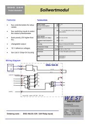
Parameter table<br />
W.E.<strong>ST</strong>. <strong>Elektronik</strong> <strong>GmbH</strong><br />
Kommando Parameter Vorgabe Einheit Beschreibung<br />
s:i x i = 0… 7<br />
x = -10000… 10000<br />
- 0,01% Command values depending on the external signal S1, S2 and S4<br />
rmode x x= SD|4Q SD - Ramp function:<br />
SD = ramp time related to the setpoint value<br />
4Q = Four quadrants ramp, ramp-variable RA:1 to RA:4 is used.<br />
ra:i x i= 0… 7<br />
x= 0..600000<br />
100 ms Ramp-time.<br />
4Q Ramp RA:1 up (solenoid A), RA:2 down (solenoid A)<br />
RA:3 up (solenoid B), RA:4 down (solenoid B)<br />
SD Ramp RA:0 to RA:7<br />
mode x x= on|off off - Activation or deactivation of the linearization defined by the CC<br />
command.<br />
cc:i x y i= -10… 10<br />
x -10000… 10000<br />
y -10000… 10000<br />
0,01%<br />
0,01%<br />
Characteristic linearization.<br />
rcurr x x= on|off off - Real current input. MIN and MAX will be typed in, in mA. If rcurr =<br />
on; the command “current” should not be used.<br />
min:i x i= A<br />
x= 0..5000<br />
max:i x i= A<br />
x= 300..10000<br />
0<br />
10000<br />
0,01% / mA<br />
0,01% / mA<br />
Deadband compensation of positive overlapped proportional<br />
valves.<br />
Maximum output range for adapting control range to maximum<br />
flow range.<br />
trigger x x= 0..2000 200 0,01% Point to activate the deadband compensation (min). Also useful<br />
for reduced sensitivity in position with control valves.<br />
sens x x= ON|OFF ON - Activation of the sensor and internal failure monitoring.<br />
solenoids x x= 1|2<br />
current:i x i= A<br />
x= 0, 1, 2<br />
dampl:i x i= A<br />
x= 0..2000<br />
dfreq:i x i= A<br />
x= 60… 400<br />
pwm:i x i= A<br />
x= 100..7700<br />
ppwm:i x<br />
ipwm:i x<br />
x= 1… 20<br />
x= 5… 100<br />
2 - Number of used solenoids. Two for directional valves, one for<br />
pressure or throttle valves.<br />
0<br />
400<br />
120<br />
2600<br />
7<br />
40<br />
-<br />
0,01%<br />
Hz<br />
Hz<br />
-<br />
-<br />
Output current range.<br />
0 = 1,0 A range<br />
1 = 1,6 A range<br />
2 = 2,6 A range<br />
DO NOT USE THIS COMMAND IF RCURR = ON.<br />
Parametering of the dither amplitude in 0,01 % units of the nominal<br />
current range. Typical values between 500 and 1200 (with 700<br />
we always had good experience).<br />
Preset of the dither frequency<br />
Preset of the PWM frequency<br />
P-gain for control dynamics of the current control loop. Changing<br />
of these parameters should only be done by expert know how. A<br />
higher P-gain increases the control dynamics of the current control<br />
and also the effect of the dither adjustment<br />
I-gain for control dynamics of the current control loop. Changing of<br />
these parameters should only be done by expert know how<br />
cmode x X= ON|OFF ON - Function of the output stage:<br />
OFF: function for closed loop positioning drives,<br />
ON: standard and for only one return line by two solenoids<br />
(HAWE valves).<br />
save - - - Storing the programmed parameter in E²PROM.<br />
loadback - - - Reloading the parameter from E²PROM in working RAM<br />
Seite 13 von 22 12.03.2008