POS-123PDP rev 11 - W.E.ST. Elektronik GmbH
POS-123PDP rev 11 - W.E.ST. Elektronik GmbH
POS-123PDP rev 11 - W.E.ST. Elektronik GmbH

Create successful ePaper yourself
Turn your PDF publications into a flip-book with our unique Google optimized e-Paper software.
W.E.<strong>ST</strong>. <strong>Elektronik</strong> <strong>GmbH</strong><br />
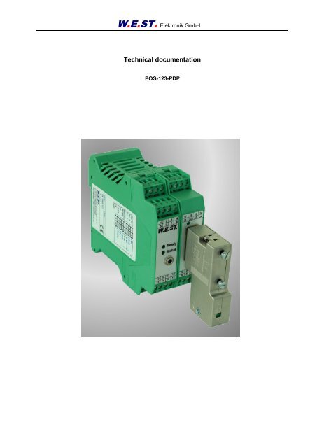
Technical documentation<br />
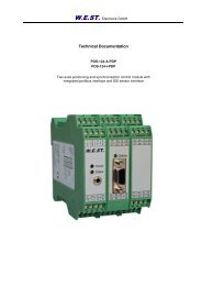
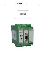
<strong>POS</strong>-123-PDP
W.E.<strong>ST</strong>. <strong>Elektronik</strong> <strong>GmbH</strong><br />
Table of contents<br />
Revisions .................................................................................................................................................4<br />
Ordering code ..........................................................................................................................................4<br />
Accessories .............................................................................................................................................4<br />
General description ..................................................................................................................................5<br />
General installation remarks .....................................................................................................................6<br />
Description of the unit ..............................................................................................................................7<br />
In- and outputs for the synchronization controller .............................................................................8<br />
LED Function...................................................................................................................................8<br />
Block diagram..................................................................................................................................9<br />
Typical wiring................................................................................................................................. 10<br />
Technical Data .............................................................................................................................. <strong>11</strong><br />
Dimensions ................................................................................................................................. <strong>11</strong><br />
General IO description ................................................................................................................... 12<br />
Power supply ............................................................................................................................... 12<br />
Digital inputs................................................................................................................................ 12<br />
Digital outputs ............................................................................................................................. 12<br />
Analogue inputs........................................................................................................................... 12<br />
Analogue outputs ........................................................................................................................ 13<br />
Serial interface ............................................................................................................................ 14<br />
Start-up and commissioning guidelines .................................................................................................. 15<br />
Parameter table ..................................................................................................................................... 16<br />
Parameter description ............................................................................................................................ 18<br />
INPX (Sensor input selection) ...................................................................................................... 18<br />
VMODE (Activation of the NC mode) ........................................................................................... 18<br />
SENS (sensor monitoring) ........................................................................................................... 18<br />
PDPADR (Profibus Address) ....................................................................................................... 18<br />
<strong>ST</strong>ROKE (Maximum stroke of the sensor) ................................................................................... 18<br />
SSIOFFSET (Sensor offset) ........................................................................................................ 19<br />
SSIRES (Resolution of the sensor) .............................................................................................. 19<br />
This sensor resolution is always used for the input data via Profibus. ........................................... 19<br />
SSIBITS (Data protocol length in Bits) ......................................................................................... 19<br />
SSICODE (Transmitting code) ..................................................................................................... 19<br />
SSIPOL (Sensor polarity) ............................................................................................................ 20<br />
AIN (input signal scaling) ............................................................................................................. 20<br />
VRAMP (ramp time for the external velocity) ................................................................................ 21<br />
VMAX (Internal maximum velocity preset) .................................................................................... 21<br />
A (acceleration time) .................................................................................................................... 21<br />
D (deceleration stroke or braking distance) .................................................................................. 21<br />
CTRL (braking characteristics)..................................................................................................... 22<br />
IN<strong>POS</strong> (in positioning window)..................................................................................................... 23<br />
HAND (Hand speed) .................................................................................................................... 23<br />
OFFSET (zero point adjustment) ................................................................................................. 23<br />
POL (output polarity) ................................................................................................................... 23<br />
MIN (compensation of the dead zone) ......................................................................................... 24<br />
MAX (maximum output signal) ..................................................................................................... 24<br />
TRIGGER (threshold value of MIN) .............................................................................................. 24<br />
DC (Setting drift compensation) ................................................................................................... 25<br />
SAVE (data storing in EEPROM) ................................................................................................. 25<br />
LOADBACK (copy of the EEPROM into the active RAM) ............................................................. 25<br />
UPLOAD (actual parameter list) ................................................................................................... 25<br />
<strong>ST</strong> (internal status) ...................................................................................................................... 26<br />
PROCESS DATA (monitoring) ..................................................................................................... 26<br />
Profibus DP linking................................................................................................................................. 27<br />
Profibus functions .......................................................................................................................... 27<br />
Installation ..................................................................................................................................... 27<br />
GSD Configuration File .................................................................................................................. 27<br />
Prozess data definition ................................................................................................................ 28<br />
Page 2 of 33
W.E.<strong>ST</strong>. <strong>Elektronik</strong> <strong>GmbH</strong><br />
Commands via PROFIBUS ............................................................................................................29<br />
DATA send to PROFIBUS .............................................................................................................30<br />
System structure............................................................................................................................32<br />
Comments .............................................................................................................................................33<br />
Page 3 of 33
Revisions<br />
W.E.<strong>ST</strong>. <strong>Elektronik</strong> <strong>GmbH</strong><br />
Date<br />
Module<br />
<strong>rev</strong>ision<br />
Comment<br />
21.12.05 <strong>11</strong>13-<strong>rev</strong> 1 New hardware, ME5 board.<br />
• Switchable sensor input (SSI and analogue)<br />
26.04.06 <strong>11</strong>13-<strong>rev</strong> 2 • Emergency brake ramp mode<br />
• Command „DIN“ replace through „<strong>ST</strong>“<br />
30.05.06 <strong>11</strong>13-<strong>rev</strong> 3 Offset input (SSI) in mm.<br />
16.06.06 <strong>11</strong>13-<strong>rev</strong> 4 Selection of SSI Sensors expanded<br />
14.02.07 <strong>11</strong>13-<strong>rev</strong> 5 High / Low and Low / High speed mode<br />
15.05.07 <strong>11</strong>13-<strong>rev</strong> 6 Velocity limitation in hand-mode<br />
New functions<br />
• New parameter calculation, neither rounding error<br />
05.06.07 <strong>11</strong>15-<strong>rev</strong> 7 • Baudrate up to 56700 Baud<br />
• Bootloader<br />
• New brake ramp calculation<br />
26.09.07 <strong>11</strong>15-<strong>rev</strong> 8 Implementation of a drift-compensator<br />
10.01.08 <strong>11</strong>15-<strong>rev</strong> 9 PO and OFFSET now for analog Input<br />
22.01.08 <strong>11</strong>15-<strong>rev</strong> 10 Number of SSI sensors extended<br />
18.02.08 <strong>11</strong>15-<strong>rev</strong> <strong>11</strong> Position Error xw is send to Profibus DP<br />
Ordering code<br />
<strong>POS</strong>-<strong>123PDP</strong> - with analogue ± 10 V output<br />
* = Version number, for ordering not necessary. Changes of the last digit (13 to 14) indicate technical improvements<br />
at 100% compatibility. Changes from 13 to 20 indicate significant technical improvements. In<br />
this case check the documentation about the parameter and wiring.<br />
Accessories<br />
RS232-SO - programming cable with RS232C interface<br />
USB-SO - programming cable with USB interface<br />
HHT-302 - Hand held terminal<br />
WPC-300 - Start up software<br />
W.E.<strong>ST</strong>. <strong>Elektronik</strong> <strong>GmbH</strong><br />
Gewerbering 31<br />
D-41372 Niederkrüchten<br />
Fax.: +49 (0) 2163 57 73 55 - <strong>11</strong><br />
Homepage: www.w-e-st.de or www.west-electronics.com<br />
EMAIL: info@w-e-st.de<br />
Date: 20.05.2008<br />
Revision: <strong>11</strong><br />
Page 4 of 33
General description<br />
W.E.<strong>ST</strong>. <strong>Elektronik</strong> <strong>GmbH</strong><br />
This electronic module is developed for controlling of hydraulic drives via an integrated Profibus DP interface.<br />
A typical repeatable positioning accuracy of up to 0,01 % with analogue sensors or up to 0,001 mm<br />
with digital SSI sensors can be achieved. Command signals and actual values are transmitted from the<br />
module to the PLC by the Profibus communication interface. Proportional valves with integrated electronics<br />
(typically with control valves) can be driven by the analogue differential output.<br />
Internal profile generation (acceleration time, max. velocity and stroke depended deceleration) provides<br />
fast and excellent positioning. The drive works in open loop mode and is switched over in closed loop during<br />
deceleration. This is a time-optimal positioning structure with very high stability. The maximal velocity<br />
can be limited by the external velocity input. An extra NC mode can be used for a speed controlled profile<br />
generation.<br />
The adjustment via RS232C is simple and easy to understand (command line input, ASCII format). A<br />
standard terminal program or a special windows application software (WPC-300, download from our<br />
homepage) can be used.<br />
Typical applications: General position control.<br />
Features<br />
Communication via Profibus DP: Command values, actual values,<br />
control word and status word<br />
Sensor resolution up to 0,001 mm<br />
Speed resolution up to 0,005 mm/s<br />
Principle of stroke depended deceleration<br />
High / Low speed profile generation<br />
Optimal use of overlapped and zero overlapped proportional valves<br />
Internal profile, defined by acceleration time, max velocity and de-<br />
celeration stroke<br />
Extern definable velocities<br />
Simple and application orientated parameter settings<br />
Failure monitoring<br />
Adjustments via RS232C interface<br />
Page 5 of 33
General installation remarks<br />
Explanation of terms and notes on safety<br />
Terms:<br />
wl: command signal<br />
xl: actual signal<br />
xw: control error (w-x)<br />
v: speed<br />
u: output signal<br />
Mounting instructions<br />
W.E.<strong>ST</strong>. <strong>Elektronik</strong> <strong>GmbH</strong><br />
This module is for the installation provided in shielded electromagnetic compatibility housing (EMC conform).<br />
All cables operating outside have to be screened. A complete shielding is presupposed. By use of our<br />
control modules it is also presupposed, that no strong electrical disturbances near the module are installed.<br />
Typical mounting area: 24V control signal area (near PLC)<br />
During the arrangement of the electrical cabinet a separation between power part (and power cables) and<br />
signal part must be taken in consideration. Experience shows us that the area next to the PLC (24 V area)<br />
is suitable. All digital and analogue inputs and outputs have filters and an over voltage protection. In<br />
case of correct wiring and shielding all EMC demands are fulfilled. If there are nevertheless any problems,<br />
please send us detailed sketches of mounting and wiring. We will look after this problem immediately.<br />
Even if all EMC-norms are fulfilled, technical problems in special cases are possible. Our experience has<br />
shown us that most of these problems are caused in the physical conditions of the cables. If everything is<br />
shielded continuously and configured correctly, no problems have to be expected.<br />
ATTENTION!<br />
ATTENTION!<br />
Due to electrical disturbances, failure at components as well as software faults can cause<br />
in individual cases uncontrolled movements at the drive. Appropriate safety precautions<br />
have to be considered during the engineering.<br />
Connection and start up of the module may only be allowed by qualified persons<br />
who have, because of education, experience and instruction, sufficient<br />
acknowledge on relevant directives and approved technical rules. Please<br />
read and follow the operating instructions carefully. In case of non observance<br />
of the instruction the guaranty and liability claim expires.<br />
Page 6 of 33
Description of the unit<br />
W.E.<strong>ST</strong>. <strong>Elektronik</strong> <strong>GmbH</strong><br />
Positioning control<br />
This module is a further development of the analogue position controller <strong>POS</strong>-123A.<br />
The <strong>POS</strong>-<strong>123PDP</strong> is a module with digital or analogue position measuring and an integrated communication<br />
via Profibus DP.<br />
It can be used as an universal axis controller for hydraulic drives.<br />
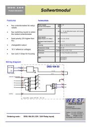
Because of a second position and a second velocity it is optionally possible to drive to this position with<br />
the corresponding speed (rapid traverse and creeping speed respectively creeping speed and rapid traverse)<br />
Positioning: Similar to the <strong>POS</strong>-123 the axis can be used as point to point controller (stroke<br />
depended deceleration) as well as in NC mode. With only a few parameters the controller can<br />
be optimized, the movement profile is preset via Profibus (position and velocity).<br />
Because of the input of a second position and speed, the axis can be driven to this position with<br />
the second velocity. This mode is only activated when the velocity command value 2 is typed<br />
in. The following features have to be noticed:<br />
- the target position is command value 2 (P2) combined with velocity 2 (V2).<br />
- the switch over position is command value 1 (P1), combined with velocity 1 (V1).<br />
Switching over position from a high to a lower speed is calculated by the deceleration function<br />
and V2.<br />
Switching over from a low to a high velocity is carried out at the position (P1) via the acceleration<br />
ramp; see below.<br />
- If the positioning command value 2 (P2) is between the actual and the position command<br />
value 1 (P1), to position 2 (P2) can only be driven with speed 1 (V1).<br />
velocity<br />
velocity<br />
V1<br />
acceleration deceleration<br />
Low to high speed<br />
V1<br />
High to low speed<br />
P1 P2<br />
Page 7 of 33<br />
V2<br />
V2<br />
P1 P2<br />
acceleration deceleration<br />
time / position<br />
time / position
W.E.<strong>ST</strong>. <strong>Elektronik</strong> <strong>GmbH</strong><br />
In- and outputs for the synchronization controller<br />
Terminal Description of the analogue inputs and outputs<br />
PIN 14 Analogue feedback value (X), range 0… 100% corresponds to 0… 10V or<br />
4… 20 mA<br />
PIN 15 / 16 Differential output (U) ± 100% corresponds to ± 10V differential voltage,<br />
optionally (I-version) current output ±100% corresponds to 4… 20 mA (PIN 15 to<br />
PIN <strong>11</strong>)<br />
Terminal Description of the digital inputs and outputs<br />
PIN 8 Enable input:<br />
This digital input signal initializes the application. The analogue output is active<br />
and the READY signal indicates that all components are working correctly. Target<br />
position is set to actual position and the drive is closed loop controlled.<br />
LED Function<br />
LEDs Description of the LED function<br />
GREEN Identical with the READY output.<br />
OFF: No power or ENABLE is inactive.<br />
ON: System in process<br />
FLASHING Failure detected (internal or 4… 20 mA).<br />
Only if SENS = ON.<br />
YELLOW Identical with the <strong>ST</strong>ATUS output.<br />
OFF: Control error depending of the error parameter.<br />
ON: No control error.<br />
Page 8 of 33
Block diagram<br />
Power supply<br />
24V<br />
0V<br />
Enable<br />
24 V<br />
0 V<br />
analogue<br />
actual position<br />
0..10V<br />
4..20mA<br />
0 V<br />
SSI<br />
actual position<br />
0 V<br />
8<br />
3<br />
4<br />
19<br />
20<br />
14<br />
<strong>11</strong><br />
25<br />
26<br />
27<br />
28<br />
31<br />
32<br />
CLK+<br />
CLK-<br />
DC<br />
DATA+<br />
DATA-<br />
24 V<br />
0 V<br />
24 V input<br />
DC<br />
W.E.<strong>ST</strong>. <strong>Elektronik</strong> <strong>GmbH</strong><br />
12 V<br />
5 V<br />
profile- generator<br />
setpoint w over<br />
the fieldbus<br />
Input Selektor<br />
ain:i a b c x <br />
i = XL<br />
a,b,c = -10000...10000<br />
x = V|C<br />
SSI Interface<br />
ssioffset x <br />
x = -30000..30000<br />
ssires x <br />
x = 10.1000<br />
ssibits x <br />
x = 8..31<br />
ssicode x <br />
x = gray | bin<br />
ssipol x<br />
x = + | -<br />
save <br />
loadback <br />
upload <br />
wl<br />
Allgemeine Kommandos<br />
offset x <br />
x = -1000.. 1000<br />
Control program<br />
SUPPORT<br />
Freigabe<br />
inpx = ana<br />
Freigabe<br />
inpx = ssi<br />
xl<br />
xw<br />
DIAGNO<strong>ST</strong>ICS<br />
st <br />
wl <br />
xl <br />
xw <br />
u <br />
v <br />
RS232 C<br />
9600 Baud<br />
1 Stopbit<br />
no parity<br />
3,5 mm JISC-6560 Buchse<br />
Deceleration A<br />
d:i x <br />
i = A<br />
x = 50..10000<br />
Deceleration B<br />
d:i x <br />
i = B<br />
x = 50..10000<br />
brakeramp<br />
d:i x <br />
i = S<br />
x = 0..10000<br />
setpoint v over<br />
the fieldbus<br />
Page 9 of 33<br />
Acceleration A<br />
a:i x <br />
i = A<br />
x = 1..2000 ms<br />
Acceleration B<br />
a:i x <br />
i = B<br />
x = 1..2000 ms<br />
CONFIGURATION<br />
inpx x (x = SSI|ANA)<br />
pdpadr x (i = 1..126)<br />
vmode x (ON | OFF)<br />
hand:i x (i = A|B, x = -10000..10000)<br />
inpos x (x = 0..1000)<br />
ctrl x (x = LIN|SQRT1|SQRT2)<br />
stroke x (x = 10..10000)<br />
sens x (ON| OFF)<br />
<strong>POS</strong>-<strong>123PDP</strong><br />
v<br />
u<br />
Driftcompensator<br />
dc:i x <br />
i = I<br />
x = 3... 30000<br />
dc:i x <br />
i = AV<br />
x = 0... 10000<br />
dc:i x <br />
i = DV<br />
x = 0... 10000<br />
dc:i x <br />
i = RA<br />
x = 0... 10000<br />
valve adaption<br />
vramp x <br />
x = 10..2000<br />
min:i x <br />
i = A|B<br />
x = 0..5000<br />
max:i x <br />
i = A|B<br />
x = 5000..10000<br />
trigger x <br />
x = 0..3000<br />
pol x <br />
x = +|-<br />
24 V output<br />
24 V output<br />
Profi-Bus<br />
SUBD 9 pol<br />
Output: A (0..10)V<br />
u<br />
PE via DIN-RAIL<br />
15<br />
16<br />
Output: B (0..10)V<br />
9 9<br />
12<br />
1<br />
2<br />
Profibus DP<br />
differenzinput from the<br />
aktuator<br />
I version: 4... 20 mA output<br />
PIN 15 = +, PIN 12 = GND<br />
Ready<br />
InPos
Typical wiring<br />
ENABLE<br />
+/- 10 V<br />
to control valve<br />
PE Klemme<br />
1<br />
5<br />
9<br />
13<br />
W.E.<strong>ST</strong>. <strong>Elektronik</strong> <strong>GmbH</strong><br />
2<br />
6<br />
10<br />
14<br />
3<br />
7<br />
<strong>11</strong><br />
15<br />
4<br />
8<br />
12<br />
16<br />
17<br />
21<br />
25<br />
29<br />
18<br />
22<br />
26<br />
30<br />
Page 10 of 33<br />
19<br />
23<br />
27<br />
31<br />
20<br />
24<br />
28<br />
32<br />
PE Klemme<br />
24V<br />
Power supply<br />
0V<br />
PE<br />
DATA-<br />
DATA+<br />
CLK-<br />
CLK+<br />
GND<br />
+24 V DC<br />
SSI / SSD<br />
sensor interface
Technical Data<br />
Power supply<br />
Current consumption<br />
External fuse<br />
Dimensions<br />
WIDTH (see technical data)<br />
W.E.<strong>ST</strong>. <strong>Elektronik</strong> <strong>GmbH</strong><br />
[VDC]<br />
[mA]<br />
[A]<br />
Digital inputs [V]<br />
[V]<br />
Digital outputs [V]<br />
[V]<br />
Analogue inputs (sensor and command<br />
signals)<br />
Resolution<br />
[V]<br />
[mA]<br />
[%]<br />
Page <strong>11</strong> of 33<br />
12… 30 (incl. ripple)<br />
400 + sensor power consumption<br />
1 (medium lag)<br />
logic 0: < 2 V<br />
logic 1: > 12 V<br />
logic 0: < 2 V<br />
logic 1: > 12 V (max. 50 mA)<br />
0...10; 33 kOhm<br />
4...20; 250 Ohm<br />
0,01 (internally 0,0031)<br />
SSI Interface RS422 specification: Bits, code, and resolution are<br />
programmable<br />
Analogue outputs<br />
Max. load<br />
Resolution<br />
[V]<br />
[mA]<br />
[mA]<br />
[%]<br />
Sample time ms 1<br />
Interface<br />
Profibus DP<br />
Baudrate<br />
ID-Nummer<br />
2 x 0...10 (differential output)<br />
5<br />
4...20 mA (I version); 390 Ohm max. load<br />
0,024<br />
RS 232C, 9600 Baud, 1 stopbit, No parity, Echo<br />
Mode<br />
9.6,19.2, 93.75, 187.5, 500, 1500, 3000, 6000,<br />
12000 kbit/s<br />
1810h<br />
Housing Snap-On Module EN 50022<br />
Polyamide PA 6.6<br />
Combustibility class V0 (UL94)<br />
Protection class<br />
Temperature range<br />
Humidity<br />
[IP]<br />
[°C]<br />
[%]<br />
Dimensions (width) [mm] 45<br />
20<br />
-20… 60<br />
General IO description<br />
W.E.<strong>ST</strong>. <strong>Elektronik</strong> <strong>GmbH</strong><br />
This description is a general description of the technical data of out open loop and closed loop control<br />
modules. Please check the implemented IO signals via the block diagram about availability.<br />
Power supply<br />
This module is designed for 12… 30 VDC (typical 24 V) of a power supply. This power supply must correspond<br />
to the actual EMC standards.<br />
All inductivities at the same power supply (relays, valves …) must be provided with an over voltage protection<br />
(varistors, free-wheel diodes …).<br />
It is recommended to use a regulated power supply (linear or switching mode) for the supply of the module<br />
and the sensors. These power supplies have a clearly lower internal resistance in comparison with<br />
non regulated power supplies and therefore a better spurious rejection.<br />
Power supply : 12… 30 VDC, incl. ripple<br />
Power consumption: 400 mA + sensor power consumption<br />
External protection: 1 A medium lag<br />
Digital inputs<br />
ATTENTION: Without an external fuse and in case of a continual short-circuit the<br />
module can be destroyed in spite of all internal protections.<br />
The digital inputs are designed for a voltage level of 12 V and 24 V. The typical connections to the PLC<br />
will not be screened if the modules are arranged carefully and with short cable lengths. As common potential<br />
0V (PIN 4) is used.<br />
All inputs are protected with suppressor diodes and RC-filters against transient overshoots.<br />
Low level: < 4 V<br />
High level: > 12 V<br />
Current: < 0,1 mA<br />
Digital outputs<br />
The digital outputs are designed for a voltage level of 12 V and 24 V. The typical connections to the PLC<br />
will not be screened if the modules are arranged carefully and with short cable lengths. As common potential<br />
0V (PIN 4) is used.<br />
All outputs are protected with suppressor diodes and RC-filters against transient overshoots.<br />
Low level: < 4 V<br />
High level: > 10 V<br />
Current: max. 50 mA (with load of 200 Ohm)<br />
Analogue inputs<br />
By use of analogue inputs you have to distinguish between symmetrical and asymmetrical inputs.<br />
All analogue inputs must be screened.<br />
The symmetrical input is carried out as a differential input for voltage signals and can be switched over<br />
per software to bipolar or unipolar signals. Especially by use of high-resolution analogue signals an additional<br />
cable twisted in pairs has to be taken.<br />
Page 12 of 33
W.E.<strong>ST</strong>. <strong>Elektronik</strong> <strong>GmbH</strong><br />
The asymmetrical inputs are optimized for the two-pole-conductor techniques (voltages or current signals<br />
as usual in the automobile industry). They can be switched over by software between voltage and<br />
current input. A low-impedance GND connection is required for good signal transmission. In this configuration<br />
the return line is the GND of the power supply. Therefore sensors and the control module should be<br />
combined at a common star point (low impedance) with the GND of the power supply. As common potential<br />
the 0V PIN <strong>11</strong> and optionally PIN 12 are used.<br />
All inputs are protected with suppressor diodes and RC-filter against transient overshoots.<br />
Differential input:<br />
Voltage level: bipolar ±10 V (PIN 9 and PIN 10)<br />
unipolar 0… 10 V (PIN 10 against PIN 9)<br />
input resistance: > 91 k<br />
Asymmetrical inputs:<br />
Voltage level: unipolar 0… 10 V (against PIN <strong>11</strong>)<br />
input resistance: 25 k<br />
Current level: unipolar 4… 20 mA (against PIN <strong>11</strong>)<br />
input resistance: app. 250 <br />
Analogue outputs<br />
The analogue outputs are carried out as symmetrical differential outputs. Because all power amplifiers<br />
have a differential input (especially valves with integrated electronics), an optimal signal transmission<br />
even over greater distances is possible. All analogue outputs have to be wired with screened cables.<br />
Ideally, twisted pair cables are used. For the signal potential or if both outputs are used as two separate<br />
asymmetrical signals (f. e. for plug amplifiers), PIN 12 as GND potential has to be used. All outputs are<br />
protected with suppressor diodes against transient overshoots.<br />
As differential output:<br />
Voltage level: bipolar ±10 V (PIN 15 and PIN 16)<br />
Output current: max. 10 mA<br />
As asymmetrical outputs:<br />
Voltage level: 2 x unipolar 0… 10 V (PIN 15 or PIN 16 against PIN 12)<br />
Output current: max. 10 mA<br />
As current output:<br />
Voltage level: 1 x unipolar 4… 20 mA (PIN 15 to PIN 12)<br />
max output current: max. 22 mA<br />
max load: 390 ohm<br />
ATTENTION! At the asymmetrical output with the 0 V potential at PIN 12 a minimal<br />
output voltage of approx 0,1 to 0,15 V exists.<br />
Page 13 of 33
Serial interface<br />
W.E.<strong>ST</strong>. <strong>Elektronik</strong> <strong>GmbH</strong><br />
The serial interface is chosen for the parametering with a PC or a notebook. A suitable cable of 3,5mm<br />
JISC-6560 plug to 9pol. RS232 (PC compatible) can be bought under RS232-SO.<br />
You can parameterize our modules with each terminal program. However, by use of our application software<br />
WPC-300 you have enlarged functions and therefore it is preferable.<br />
Download: WWW.WE<strong>ST</strong>-ELECTRONICS.COM or WWW.W-E-<strong>ST</strong>.DE<br />
Features:<br />
Table orientated parametering<br />
Saving and loading of the parameter sets<br />
Process data monitoring<br />
Oscilloscope for dynamical optimization of the control parameters<br />
Terminal window for flexible data input<br />
Page 14 of 33
W.E.<strong>ST</strong>. <strong>Elektronik</strong> <strong>GmbH</strong><br />
Start-up and commissioning guidelines<br />
1. The module must be mounted and wired with attentions to EMC requirements. A star orientated<br />
ground connection should be used when other power consumers are sharing the same power<br />
supply. Following points have to be taken in account for wiring:<br />
Signal cable and power cable have to be wired separately.<br />
Analogue signal cables must be screened.<br />
Other cables should be screened in case of strong electrical disturbance (power relays,<br />
frequency controlled power driver). With high frequency EMI inexpensive ferrite elements<br />
can be used. In this typical configuration of installation (see point 2 to 4), no extra step<br />
should be taken in consideration.<br />
2. By the arrangement of the electrical cabinet a separation between the power part (and power cables)<br />
and signal part must be taken in consideration. Experience shows us that the area next to<br />
the PLC (24 V area) is suitable.<br />
3. Low impedance between PE “protected earth” and DIN-Rail should be used. Transient interference<br />
voltages at the terminals are discharged via DIN-Rail to the local PE. The screens have to<br />
be connected directly next to the module via PE terminals.<br />
4. The power supply should be carried out voltage regulated (that is PWM controlled). The low impedance<br />
of controlled power supplies facilitates improved interference damping. Therefore the<br />
signal resolution will be increased. Switched inductance (relays and solenoids) operating from the<br />
same power supply has to be damped by surge protection elements directly by the inductance.<br />
5. According to the motion diagram, the power amplifier- / valve- / drive combination should drive<br />
out with positive output signal (PIN 15 to PIN 16) and the output voltage of the sensor heightens.<br />
ATTENTION: This output is a differential output. Both outputs may not be<br />
connected with 0V.<br />
Page 15 of 33
Parameter table<br />
W.E.<strong>ST</strong>. <strong>Elektronik</strong> <strong>GmbH</strong><br />
Commands Parameter Defaults Units Description<br />
inpx X= SSI|ANA SSI - Selection of the sensor input channel.<br />
vmode x X= on|off Off - Activation of the NC-generator. The command position is generated<br />
by a velocity profile (internal or external preset of v). The axis<br />
drives more or less speed controlled.<br />
sens x x= on|off on - Activation of the sensor and internal failure monitoring.<br />
pdpadr x X= 1… 126 5 - Profibus address<br />
stroke x X= 2… 3000 200 mm Sensor stroke.<br />
ssioffset X X=<br />
-300000… 300000<br />
0 0,01 mm Zero point adjustment of the sensor.<br />
ssires X X= 1… 5000 1000 ink/mm Resolution of the sensor.<br />
ssibits x X= 8… 32 24 - Bits of the data word.<br />
ssicode x X= GRAY|BIN GRAY - Format of the data word.<br />
ssipol x X= +|- + - Sensor polarity, attention: SSIOFFSET has to be set to compensate<br />
negative position values.<br />
ain:i a b c x i= XL<br />
a= -10000… 10000<br />
b= -10000… 10000<br />
c= -10000… 10000<br />
x= V|C<br />
: 10000<br />
: 10000<br />
: 0<br />
: V<br />
-<br />
-<br />
0,01%<br />
-<br />
vramp x X= 1… 2000 200 ms Ramp time for velocity input.<br />
Page 16 of 33<br />
Analogue input scaling. XL for the input and V = voltage.<br />
C = current. With the parameters a, b and c the inputs can be<br />
scaled (output = a / b * (input - c)).<br />
Because of the programming of the x-value (x = C) the corresponding<br />
input will be switched over to current automatically.<br />
vmax x X= 1… 20000 50 mm/s Parameter is active in vmode = ON only.<br />
VEL defines the maximum speed. Via the external command<br />
speed an actual speed between 0,5… 100 % can be selected.<br />
a:i x i= A|B<br />
X= 1… 2000<br />
d:i x i= A|B|S<br />
X(A,B)= 50… 10000<br />
X(S)= 0… 10000<br />
ctrl x X= lin|sqrt1<br />
|sqrt2<br />
:A 200<br />
:B 200<br />
:A 2500<br />
:B 2500<br />
:S 1000<br />
ms<br />
ms<br />
0,01%<br />
0,01%<br />
0,01%<br />
Acceleration time depending on direction. A indicates analogue<br />
output 15 and B indicates analogue output 16.<br />
Normally A = flow p-A, B-T and B = flow P-B, A-T.<br />
Deceleration stroke depending on direction. The loop gain is calculated<br />
by the deceleration stroke. The shorter the higher. In case<br />
of instabilities longer deceleration stroke will be sufficient.<br />
sqrt1 - Selection of the control function: lin = standard linear P-control,<br />
sqrt1 = progressive time optimized deceleration curve, sqrt2 =<br />
sqrt1 with a higher gain in position<br />
inpos x X= 0… 5000 32 0,01% Range for the InPos signal (status output).<br />
hand:i x i= A|B<br />
X= -10000… 10000<br />
:A 3300<br />
:B -3300<br />
0,01%<br />
0,01%<br />
Degree of output signal in manual mode<br />
offset x X= -2000… 2000 0 0,01% The offset will be added to the command value.<br />
pol x x= +|- + - For changing the output polarity. All A and B adjustments depend<br />
on the output polarity. The right polarity should be defined first.<br />
min:i x i= A|B<br />
x= 0… 5000<br />
max:i x i= A|B<br />
X= 5000… 10000<br />
:A 0<br />
:B 0<br />
:A 10000<br />
:B 10000<br />
0,01%<br />
0,01%<br />
0,01%<br />
0,01%<br />
Deadband compensation of positive overlapped proportional<br />
valves. Good adjustment will increase positioning accuracy.<br />
Maximum output range for adapting control range to maximum<br />
flow range.<br />
trigger x X= 0… 2000 200 0,01% Point to activate the deadband compensation (min). Also useful<br />
for reduced sensitivity in position with control valves.
W.E.<strong>ST</strong>. <strong>Elektronik</strong> <strong>GmbH</strong><br />
Commands Parameter Defaults Units Description<br />
dc:i x i= I|AV|DV|RA<br />
I:x = 3… 30000<br />
AV:x = 0… 10000<br />
DV:x = 0… 10000<br />
RA:x = 0… 10000<br />
I:x 1300<br />
AV:x 0<br />
DV:x 0<br />
RA:x 500<br />
ms<br />
0,01%<br />
0,01%<br />
0,01%<br />
Page 17 of 33<br />
Activation and adjustment of the Drift-compensator. . If necessary,<br />
the drift compensation with "DC: AV x" in a catchment area activated<br />
and the target range by "DC: DV x" disabled. "DC: I x", the<br />
time constant and "DC: RA x" value area of the integrator.<br />
save - - - Storing the programmed parameter in E²PROM.<br />
loadback - - - Reloading the parameter from E²PROM in working RAM<br />
upload - - - Parameter list with programmed data, for terminal programs only<br />
st - - - Status of the digital inputs.<br />
wl, xl, xw, u,<br />
v<br />
- - - Actual signals: command value, actual value, process data, control<br />
divergence and reference value.<br />
default - - - Preset values will be set.
Parameter description<br />
INPX (Sensor input selection)<br />
W.E.<strong>ST</strong>. <strong>Elektronik</strong> <strong>GmbH</strong><br />
Command Parameter Default Unit<br />
inpx:I x x= SSI|ANA SSI -<br />
This parameter determined the selection of the sensor input. The standard is a digital sensor with SSI<br />
specification at the corresponding connections (clamps 25 to 28 and 31, 32). Alternatively an analogue<br />
input which is indicated in the command as parameters “ANA” can be used. The command AIN is used<br />
for input scaling of the analogue input.<br />
VMODE (Activation of the NC mode)<br />
Commands Parameter Defaults Units<br />
vmode x x= ON|OFF OFF<br />
With this parameter the NC mode (almost closed loop controlled velocity) will be activated. In OFF state<br />
the stroke depended deceleration is active; the velocity preset limits the output signal.<br />
In ON state a profile generator generates the positioning demand value and the axis drives to the target<br />
position with the defined velocity. The stroke time is defined by the parameter VEL.<br />
SENS (sensor monitoring)<br />
Commands Parameter Defaults Units<br />
sens x x= ON|OFF ON -<br />
The sensor monitoring can be activated (with 4… 20 mA sensors).<br />
PDPADR (Profibus Address)<br />
Command Parameter Default Unit<br />
pdpadr X= 1… 126 5 -<br />
Number of the address for Profibus communication<br />
<strong>ST</strong>ROKE (Maximum stroke of the sensor)<br />
Command Parameter Default Unit<br />
stroke X= 2… 3000 200 mMm<br />
With this parameter the length of the sensor is given.<br />
The length of the sensor is needed for the scaling of the analogue input and for the calculation of the<br />
braking stroke.<br />
Page 18 of 33
SSIOFFSET (Sensor offset)<br />
W.E.<strong>ST</strong>. <strong>Elektronik</strong> <strong>GmbH</strong><br />
Command Parameter Default Unit<br />
ssioffset x x=<br />
-300000… 3000000<br />
With this parameter the offset of the sensor is given.<br />
SSIRES (Resolution of the sensor)<br />
0 0,01 mm<br />
Command Parameter Default Unit<br />
ssires x x= 1… 5000 1000 inkr/mm<br />
With this parameter the resolution of the sensor is given.<br />
The highest resolution (1000) corresponds to 1 µm. In the first place this resolution is needed for the internal<br />
calculations.<br />
This sensor resolution is always used for the input data via Profibus.<br />
SSIBITS (Data protocol length in Bits)<br />
Command Parameter Default Unit<br />
ssibits x x= 8… 32 24 bits<br />
With this parameter the number of bits of the sensor is given.<br />
SSICODE (Transmitting code)<br />
Command Parameter Default Unit<br />
ssicode x x= GRAY|BIN GRAY -<br />
With this parameter the transmitting code of the sensor is given.<br />
Page 19 of 33
SSIPOL (Sensor polarity)<br />
W.E.<strong>ST</strong>. <strong>Elektronik</strong> <strong>GmbH</strong><br />
Command Parameter Default Unit<br />
ssipol x x= +|- + -<br />
In order to <strong>rev</strong>erse the working direction of the sensor, the polarity can be changed via this command.<br />
In Any Case also the SSIOFFSET has to be adjusted.<br />
Example:<br />
Sensor length = 200 mm opposite working direction is necessary.<br />
SSIPOL is set on “-“ and SSIOFFSET on 20000.<br />
AIN (input signal scaling)<br />
Commands Parameter Defaults Units<br />
ain:i a b c x i= XL<br />
a= 0… 10000<br />
b= 0… 10000<br />
c= -10000… 10000<br />
x= V|C<br />
: 1000<br />
: 1000<br />
: 0<br />
: V<br />
Page 20 of 33<br />
-<br />
-<br />
0,01%<br />
-<br />
With this command each input can be scaled individually. For the scaling function the following linear<br />
equation is taken.<br />
a<br />
y <br />
<br />
b<br />
x c<br />
x is the input signal and y is the output signal.<br />
At first the offset (c) will be subtracted (in 0,01% units) from the input signal, then the signal will be multiplied<br />
with factor a / b. a and b should always be positive. With these both factors every floating-point value<br />
can be simulated (for example: 1.345 = 1345 / 1000).<br />
With the x parameter value the internal measuring resistance for the current measuring (0… 20 mA or<br />
4… 20 mA) will be activated (V for voltages input and C for current input). ATTENTION: This resistor is<br />
never activated at the k input.<br />
AIN:xx a b c x<br />
i with voltage: AIN:i 1000 1000 0 V<br />
i with current: AIN:i 1250 1000 2000 C
W.E.<strong>ST</strong>. <strong>Elektronik</strong> <strong>GmbH</strong><br />
VRAMP (ramp time for the external velocity)<br />
Commands Parameter Defaults Units<br />
vramp x x= 1… 2000 200 ms<br />
Here the ramp time for velocity changes will be set.<br />
Operating shocks can be reduced when changing the external velocity.<br />
VMAX (Internal maximum velocity preset)<br />
Command Parameter Default Unit Description<br />
vmax x x= 1… 20000 50 mm/s<br />
Here the maximum velocity can be limited internally. This parameter is only active in case of<br />
VMODE = ON.<br />
A (acceleration time)<br />
Commands Parameter Defaults Units<br />
a:i x i= A|B<br />
x= 0… 2000<br />
:A 200<br />
:B 200<br />
This parameter is set in ms.<br />
The ramp time is separately set for driving out (A) and for driving in (B).<br />
D (deceleration stroke or braking distance)<br />
Commands Parameter Defaults Units<br />
d:i x i= A|B|S<br />
x(A,B)<br />
= 50… 10000<br />
x(S)= 0… 10000<br />
:A 2500<br />
:B 2500<br />
:S 1000<br />
Page 21 of 33<br />
ms<br />
ms<br />
0,01%<br />
0,01%<br />
0,01%<br />
This parameter is set in 0,01 % units of the maximum length of the sensor.<br />
The braking distance is set dependent from the direction. The controller gain will be calculated by means<br />
of the braking distance. The shorter the braking distance the higher the gain (see command CTRL). In<br />
case of instabilities a longer braking distance should be set. With the parameter D: S ratio as indication of<br />
the maximum length sensor, a brake indicated only after the removal of the start signal is activated.
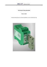
CTRL (braking characteristics)<br />
W.E.<strong>ST</strong>. <strong>Elektronik</strong> <strong>GmbH</strong><br />
Commands Parameter Defaults Units<br />
ctrl x x= lin|sqrt1<br />
|sqrt2<br />
sqrt1 -<br />
With this parameter, the braking characteristic of the hydraulic axis is controlled. With positive overlapped<br />
proportional valves one of both SQRT braking characteristics should be used. The nonlinear flow curve of<br />
the valves is mostly linearized by the SQRT function.<br />
If zero overlapped proportional valves (control valves) are used, you can choose between LIN and<br />
SQRT1 according to the application. The progressive gain characteristic of SQRT1 has the better positioning<br />
accuracy. According to the application there is maybe a longer braking distance, so that the total<br />
stroke time will be longer.<br />
LIN: Linear braking characteristics (control gain corresponds to: 10000 / d:i).<br />
SQRT1: Root function for the calculation for the braking curve. The control gain goes up quadratic<br />
with a small control error (control gain corresponds to: 30000 / d:i). This characteristic<br />
is preferably used with positive overlapped proportional valves.<br />
SQRT2: Root function for the calculation for the braking curve. The control gain goes up quadratic<br />
with a small control error (control gain corresponds to: 50000 / d:i).<br />
Velocity<br />
CTRL = LIN<br />
Page 22 of 33<br />
Braking stroke<br />
D:A or D:B<br />
Stroke<br />
CTRL = SQRT
IN<strong>POS</strong> (in positioning window)<br />
W.E.<strong>ST</strong>. <strong>Elektronik</strong> <strong>GmbH</strong><br />
Commands Parameter Defaults Units<br />
inpos x x= 0… 2000 200 0,01mm<br />
This parameter is entered in 0,01 mm units.<br />
The IN<strong>POS</strong> command defines the window when the IN<strong>POS</strong> message is indicated. The positioning<br />
process is not influenced by this message. The controller remains active.<br />
In NC-mode this message has to be interpreted as following error control.<br />
HAND (Hand speed)<br />
Commands Parameter Defaults Units<br />
hand:i x<br />
i= A|B<br />
x= -10000… 10000<br />
:A 3330<br />
:B -3330<br />
Page 23 of 33<br />
0,01%<br />
0,01%<br />
With this parameter, the hand speed can be preset. For the corresponding switch input the direction can<br />
be defined by the sign.<br />
The hand speed is also limited by the external velocity preset (MIN evaluation).<br />
OFFSET (zero point adjustment)<br />
Commands Parameter Defaults Units<br />
offset x<br />
x= -2000… 2000 0 0,01%<br />
This parameter is entered in 0,01% units.<br />
The corresponding OFFSET will be added to the control error (demand value - actual value + offset). With<br />
this parameter the zero point failure can be compensated.<br />
POL (output polarity)<br />
Commands Parameter Defaults Units<br />
pol x x= +|- + -<br />
The output polarity of the controller can be switched over.
MIN (compensation of the dead zone)<br />
MAX (maximum output signal)<br />
TRIGGER (threshold value of MIN)<br />
W.E.<strong>ST</strong>. <strong>Elektronik</strong> <strong>GmbH</strong><br />
Commands Parameter Defaults Units<br />
min:i x<br />
max:i x<br />
trigger x<br />
i= A|B<br />
x= 0… 5000<br />
x= 5000… 10000<br />
x= 0… 2000<br />
-<br />
0<br />
10000<br />
200<br />
Page 24 of 33<br />
-<br />
0,01%<br />
0,01%<br />
0,01%<br />
With this command, the output signal is adjusted to the valve characteristics. The positioning controllers<br />
have a double-gain characteristic curve instead of a typical overlapped jump. The advantage is a better<br />
and more stabile positioning behaviour. With this compensation, non-linear volume flow characteristic<br />
curves can be adjusted too.<br />
MIN:B<br />
MAX:B<br />
ATTENTION: If there exist also possibilities for adjustments at the valve or at the valve<br />
electronics, it has to be guaranteed, that the adjustment has to be carried out at the power<br />
amplifier or at the positioning module.<br />
If the MIN value is set too high, it influences the minimal velocity, which cannot be adjusted<br />
any longer. In extreme case this causes to an oscillating around the closed loop<br />
controlled position.<br />
Output<br />
two flow gain<br />
characteristics<br />
TRIGGER<br />
standard deadband<br />
compensation<br />
Input<br />
MAX:A<br />
MIN:A
DC (Setting drift compensation)<br />
W.E.<strong>ST</strong>. <strong>Elektronik</strong> <strong>GmbH</strong><br />
Kommando Parameter Vorgabe Einheit<br />
dc:i x i= I|AV|DV|RA<br />
I:x = 3… 30000<br />
AV:x = 0… 10000<br />
DV:x = 0… 10000<br />
RA:x = 0… 10000<br />
I:x 1300<br />
AV:x 0<br />
DV:x 0<br />
RA:x 500<br />
Page 25 of 33<br />
ms<br />
0,01%<br />
0,01%<br />
0,01%<br />
The drift compensation is a possible way, to p<strong>rev</strong>ent drift axis in the target position.<br />
By adding a switch integral part of the alternate value is the axis effectively held in position. The parameter<br />
DC: I define the setting time of the integral share.<br />
The activation threshold "DC: AV x" is in percent of the stated value.<br />
Below the absolute value of the signal in relation to this parameter is the drift Compensator activated.<br />
Immediately to the position of the target position can be disabled the integrator again, this is the commando<br />
"DC: DV x", whose value is also in percent of the value entered.<br />
The target range of the drift compensation is determined by the command DC: RA.<br />
In default of the module is the drift compensation off by the parameters "DC: AV 0" and DC: DV 0.<br />
SAVE (data storing in EEPROM)<br />
Commands Parameter Defaults Units<br />
save - - -<br />
Every parameter change is immediately active but only saved in RAM. For permanent storing in<br />
EEPROM the command SAVE has to be used to copy the parameter from RAM into EEPROM memory.<br />
LOADBACK (copy of the EEPROM into the active RAM)<br />
Commands Parameter Defaults Units<br />
loadback - - -<br />
With this command, the data will be written back from EEPROM to RAM. This is helpful when the p<strong>rev</strong>ious<br />
control parameter (before the last saving) will be reactivated.<br />
UPLOAD (actual parameter list)<br />
Commands Parameter Defaults Units<br />
para - - -<br />
A compact list of all programmed parameter values.
<strong>ST</strong> (internal status)<br />
W.E.<strong>ST</strong>. <strong>Elektronik</strong> <strong>GmbH</strong><br />
Commands Parameter Defaults Units<br />
st - - -<br />
Monitoring of the control and status word.<br />
With the command „<strong>ST</strong>“, in terminal mode of the application software WPC-300, the control word can be<br />
carried out in binary code: Format control word: 0000 0000 / 0000 0000<br />
Left to the slash stands the Byte 1- control word or status word “Hi“, then Byte 2- control word or status<br />
word “Lo“<br />
Bit 8 begins in the first place (Enable or Ready)<br />
PROCESS DATA (monitoring)<br />
Commands Parameter Units<br />
wl<br />
Demand value<br />
0,01 mm<br />
xl<br />
Actual value<br />
xw<br />
Control deviation<br />
v<br />
Velocity<br />
u<br />
Actuator signal<br />
The process data can be read out now. They show the actual and command values.<br />
Page 26 of 33
Profibus DP linking<br />
Profibus functions<br />
W.E.<strong>ST</strong>. <strong>Elektronik</strong> <strong>GmbH</strong><br />
The module supports all baud rates from 9,6 kbit/s up to 12000 kbit/s with auto detection of the baud rate.<br />
The functionality is defined in IEC 6<strong>11</strong>58. The Profibus address can be programmed by a terminal program,<br />
WPC-300 or online via the Profibus. A diagnostic LED indicates the online status.<br />
Installation<br />
A typical screened Profibus plug (D-Sub 9pol with switchable termination) is mandatory.<br />
Every Profibus segment must be provided with an active bus termination at the beginning and at the end.<br />
The termination is already integrated in all common Profibus plugs and can be activated by DIL switches.<br />
The Profibus cable must be screened. PIN 17 have to be connected with PE (low impedance).<br />
GSD Configuration File<br />
The GSD data are available on our homepage http://www.w-e-st.de/DE/Produkte/produkte.html file:<br />
hms_1810.gsd.<br />
The communication parameter are 16 bytes (8 words) for IN and OUTPUT variables.<br />
Page 27 of 33
Prozess data definition<br />
W.E.<strong>ST</strong>. <strong>Elektronik</strong> <strong>GmbH</strong><br />
The resolution (data via Profibus) of the command position is defined by the actual sensor resolution. The<br />
module works always with full sensor accuracy.<br />
The scaled speed is defined by 0x3fff (16373) for 100% of the maximum programmed speed.<br />
Optional two positions and two speeds can be sent to the module. In this mode high/low speed or<br />
low/high speed profiles are generated automatically. This mode is deactivated by programming zero for<br />
speed 2.<br />
The module will be controlled by the control word, the command positions and speeds:<br />
ENABLE: is additionally required to the hardware ENABLE.<br />
<strong>ST</strong>ART: the new command position is taken over by a signal change from low to high<br />
(from 0 to 1). By deactivation of this bit, the system stops via a programmed deceleration<br />
ramp.<br />
HAND+, HAND-: Manual mode<br />
Command values:<br />
Command position 1 and 2: related to the sensor resolution.<br />
Command velocity 1 and 2: 100 % corresponds to 0x3fff.<br />
Feedback of the status word, the command position and the actual position<br />
READY: System is ready for positioning.<br />
InPos: In position signal.<br />
Sensor error: if the sensor control is activated and if there exists a sensor failure, the<br />
READY signal will be deactivated.<br />
In case of a sensor failure (READY signal) the hardware-enable-signal has to be deactivated.<br />
Actual values:<br />
Command position: Can be interpreted variously according to the mode.<br />
Normal = preset command position,<br />
NC-Modus = calculated command position of the generator,<br />
Actual position: corresponding to the sensor solution.<br />
Control deviation (x-w): according to the sensor resolution.<br />
In the NC-mode shows the contouring error (difference in the value of the nominal value<br />
generator to the actual value). Control deviation (x-w): according to the sensor resolution.<br />
Page 28 of 33
Commands via PROFIBUS<br />
16 data bytes are sent to the module.<br />
Definition of the control word:<br />
W.E.<strong>ST</strong>. <strong>Elektronik</strong> <strong>GmbH</strong><br />
Byte Function Comment<br />
1 (0) control word Hi<br />
2 (1) control word Lo actual not used<br />
3 (2) command position 1 Hi<br />
4 (3) command position 1<br />
5 (4) command position 1<br />
6 (5) command position 1 Lo<br />
7 (6) velocity 1 Hi<br />
8 (7) velocity 1 Lo<br />
9 (8) command position 2 Hi active, if a second velocity is pro-<br />
10 (9) command position 2<br />
grammed ( Byte 13 und 14 )<br />
<strong>11</strong> (10) command position 2<br />
12 (<strong>11</strong>) command position 2 Lo<br />
13 (12) velocity 2 Hi<br />
14 (13) velocity 2 Lo<br />
15 (14) - reserved<br />
16 (15) - reserved<br />
Byte 1 (0) - control word Hi<br />
Bit Function<br />
8 (7) Enable (with hardware enable) 1= ready<br />
7 (6) Start 1= active<br />
6 (5) Hand- 1= active<br />
5 (4)<br />
4 (3)<br />
3 (2)<br />
2 (1)<br />
1 (0)<br />
Hand+ 1= active<br />
Byte 3 (2) bis 6 (5) - command position 1<br />
Bit Function<br />
25 (24)…32 (31) command position Hi Byte defined by the<br />
17 (16)…24 (23)<br />
9 (8)…16 (15)<br />
1 (0)…8 (7) command position Lo Byte<br />
Page 29 of 33<br />
resolution of the<br />
sensor<br />
Byte 7 (6) und 8 (7) - command velocity 1<br />
Bit Function<br />
9 (8)…16 (15) velocity Hi Byte max 3f hex<br />
1 (0)…8 (7) velocity Lo Byte max ff hex
W.E.<strong>ST</strong>. <strong>Elektronik</strong> <strong>GmbH</strong><br />
Byte 9 to 12 - command position 2<br />
Bit Function<br />
25 bis 32 command position Hi Byte defined by the<br />
17 bis 24<br />
9 bis 16<br />
1 bis 8 command position Lo Byte<br />
Page 30 of 33<br />
resolution of the<br />
sensor<br />
Byte 13 and 14 - command velocity 2<br />
Bit Function<br />
9 bis 16 velocity Hi Byte max 3f hex<br />
1 bis 8 velocity Lo Byte max ff hex<br />
The enable bit is combined with the external enable input, that means both signals must exist, in order to<br />
enable the axes.<br />
DATA send to PROFIBUS<br />
Totally, 16 Bytes will be sent to the Profibus.<br />
Byte Function Comment<br />
1 (0) status word Hi<br />
2 (1) status word Lo not used<br />
3 (2) actual position Hi<br />
4 (3) actual position<br />
5 (4) actual position<br />
6 (5) actual position Lo<br />
7 (6) internal command position Hi<br />
8 (7) internal command position<br />
9 (8) internal command position<br />
10 (9) internal command position Hi<br />
<strong>11</strong> (10) Control deviation Hi In resolution of the positioning<br />
12 (<strong>11</strong>) Control deviation<br />
sensor<br />
13 (12) Control deviation<br />
14 (13) Control deviation Lo<br />
15 (14) -<br />
16 (15) -
The status word is encoded as follows:<br />
W.E.<strong>ST</strong>. <strong>Elektronik</strong> <strong>GmbH</strong><br />
Byte 1 (0) - status word Hi<br />
Bit Function<br />
8 (7) READY 1= ready-to-operate<br />
7 (6)<br />
6 (5)<br />
5 (4)<br />
4 (3)<br />
3 (2)<br />
2 (1)<br />
1 (0)<br />
IN<strong>POS</strong> 1= value in pos-window<br />
Byte<br />
Byte 3 (2) bis 6 (5) command position<br />
Function Comment<br />
25 (24)…32 (31) command position Hi-Byte In resolution of the positioning<br />
17 (16)…24 (23) command position<br />
sensor<br />
9 (8)…16 (15) command position<br />
1 (0)…8 (7) command position Lo-Byte<br />
Byte<br />
Byte 7 (6) bis 10 (9) internal command position<br />
Function Comment<br />
25 (24)…32 (31) internal command position Hi-Byte In resolution of the positioning<br />
17 (16)…24 (23) internal command position<br />
sensor<br />
9 (8)…16 (15) internal command position<br />
1 (0)…8 (7) internal command position Lo-Byte<br />
Byte<br />
Byte <strong>11</strong> (10) bis 14 (13) Control deviation<br />
Function Comment<br />
25 (24)…32 (31) Control deviation Hi-Byte In resolution of the positioning<br />
17 (16)…24 (23) Control deviation<br />
sensor<br />
9 (8)…16 (15) Control deviation<br />
1 (0)…8 (7) Control deviation Lo-Byte<br />
Page 31 of 33
System structure<br />
Output<br />
W.E.<strong>ST</strong>. <strong>Elektronik</strong> <strong>GmbH</strong><br />
Enable<br />
8<br />
<strong>POS</strong>-<strong>123PDP</strong><br />
Addr= 5 (Slave)<br />
Abschluss =<br />
SSI or analogue position sensor<br />
Page 32 of 33<br />
Profibus DP
Comments<br />
W.E.<strong>ST</strong>. <strong>Elektronik</strong> <strong>GmbH</strong><br />
Page 33 of 33