POS-122-1113
POS-122-1113
POS-122-1113

Create successful ePaper yourself
Turn your PDF publications into a flip-book with our unique Google optimized e-Paper software.
W.E.ST. Elektronik GmbH<br />
Technical Documentation<br />
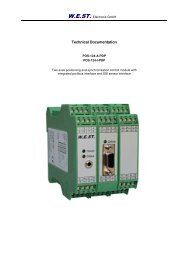
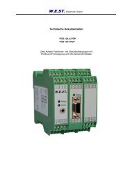
<strong>POS</strong>-<strong>122</strong>-A<br />
<strong>POS</strong>-<strong>122</strong>-I<br />
<strong>POS</strong>-<strong>122</strong>-P<br />
Positioning module
W.E.ST. Elektronik GmbH<br />
CONTENTS<br />
1 General Information .............................................................................................................................................. 4<br />
1.1 Order number ............................................................................................................................................... 4<br />
1.2 Scope of supply ............................................................................................................................................ 4<br />
1.3 Accessories .................................................................................................................................................. 4<br />
1.4 Symbols used ............................................................................................................................................... 5<br />
1.5 Using this documentation ............................................................................................................................. 5<br />
1.6 Legal notice .................................................................................................................................................. 5<br />
1.7 Safety instructions ........................................................................................................................................ 6<br />
2 Characteristics ...................................................................................................................................................... 7<br />
2.1 Device description ........................................................................................................................................ 8<br />
3 Use and application .............................................................................................................................................. 9<br />
3.1 Installation instructions ................................................................................................................................. 9<br />
3.2 Typical system structure ............................................................................................................................. 10<br />
3.3 Method of operation .................................................................................................................................... 11<br />
3.4 Commissioning ........................................................................................................................................... 12<br />
4 Technical description .......................................................................................................................................... 13<br />
4.1 Input and output signals ............................................................................................................................. 13<br />
4.2 LED definitions ........................................................................................................................................... 14<br />
4.3 Circuit diagram ........................................................................................................................................... 15<br />
4.4 Typical cabling ............................................................................................................................................ 16<br />
4.5 Technical data ............................................................................................................................................ 17<br />
5 Parameters ......................................................................................................................................................... 18<br />
5.1 Parameter overview .................................................................................................................................... 18<br />
5.2 Parameter description ................................................................................................................................ 19<br />
5.2.1 S (Presetting command values) ......................................................................................................... 19<br />
5.2.2 VC (Presetting velocities) ................................................................................................................... 19<br />
5.2.3 DSEL (Deactivation of the S-VALID) ................................................................................................. 20<br />
5.2.4 A (Acceleration time).......................................................................................................................... 20<br />
5.2.5 D (Deceleration /braking distance) ..................................................................................................... 20<br />
5.2.6 CTRL (Deceleration function characteristic) ...................................................................................... 21<br />
5.2.7 VMODE (Switching over the control mode) ....................................................................................... 22<br />
5.2.8 TH (Stroke time for speed controlled axis ) ........................................................................................ 22<br />
5.2.9 HAND (Manual speed) ....................................................................................................................... 22<br />
5.2.10 MIN (Deadband compensation) ......................................................................................................... 23<br />
5.2.11 MAX (Limitation / Gain ) ..................................................................................................................... 23<br />
5.2.12 TRIGGER (Response threshold for the MIN parameter) ................................................................... 23<br />
5.2.13 IN<strong>POS</strong> (In position window) ............................................................................................................... 24<br />
5.2.14 OFFSET (Zero correction) ................................................................................................................. 24<br />
5.2.15 POL (Output polarity) ......................................................................................................................... 24<br />
5.2.16 SENS (Module monitoring) ................................................................................................................ 25<br />
5.2.17 DIN (Input status) ............................................................................................................................... 25<br />
5.2.18 PROCESS DATA (Monitoring) ........................................................................................................... 25<br />
6 Appendix ............................................................................................................................................................ 26<br />
6.1 Failure monitoring ....................................................................................................................................... 26<br />
6.2 Troubleshooting .......................................................................................................................................... 26<br />
6.3 Description of the command structure ........................................................................................................ 28<br />
7 ADDITIONAL INFORMATION: Power output stage ........................................................................................... 29<br />
7.1 General function ......................................................................................................................................... 29<br />
7.2 Device description ...................................................................................................................................... 30<br />
7.3 Inputs and outputs ...................................................................................................................................... 31<br />
Page 2 of 36 <strong>POS</strong>-<strong>122</strong>-*-<strong>1113</strong> 06.06.2012
W.E.ST. Elektronik GmbH<br />
7.4 Circuit diagram ........................................................................................................................................... 31<br />
7.5 Typical cabling ........................................................................................................................................... 32<br />
7.6 Technical data ............................................................................................................................................ 32<br />
7.7 Parameters ................................................................................................................................................ 33<br />
7.7.1 Parameter overview .......................................................................................................................... 33<br />
7.8 Parameter description ................................................................................................................................ 33<br />
7.8.1 CURRENT (Current range switchover) ............................................................................................. 33<br />
7.8.2 DFREQ (Dither frequency) ................................................................................................................ 33<br />
7.8.3 DAMPL (Dither amplitude)................................................................................................................. 33<br />
7.8.4 PWM (PWM frequency) ..................................................................................................................... 34<br />
7.8.5 PPWM (Solenoid current controller P element) ................................................................................. 34<br />
7.8.6 IPWM (Solenoid current controller I element) .................................................................................... 34<br />
8 Notes.................................................................................................................................................................. 35<br />
Page 3 of 36 <strong>POS</strong>-<strong>122</strong>-*-<strong>1113</strong> 06.06.2012
1 General Information<br />
1.1 Order number<br />
W.E.ST. Elektronik GmbH<br />
<strong>POS</strong>-<strong>122</strong>-A-<strong>1113</strong> 1 - with analogue ±10 V differential output and analogue sensor interface<br />
<strong>POS</strong>-<strong>122</strong>-I-<strong>1113</strong> - with analogue 4… 20 mA output and analogue sensor interface<br />
<strong>POS</strong>-<strong>122</strong>-P-<strong>1113</strong> - (see additional information) with integrated power output stage up to 2,6 A<br />
1.2 Scope of supply<br />
To the scope of supply belongs the module including the terminal blocks which are part of the housing. The<br />
Profibus plug, interface cables and further parts which may be required should be ordered separately. This<br />
documentation can be downloaded as a PDF file from www.w-e-st.de.<br />
1.3 Accessories<br />
RS232-SO - Programming cable with RS232C interface<br />
USB-SO - Programming cable with USB interface<br />
WPC-300 - Start-Up-Tool (downloadable – products/software)<br />
1 The number of the version consists of the hardware-version (first two digits) and the software-version (second two<br />
digits). Because of the development of the products these numbers can vary. They are not strictly necessary for the<br />
order. We will always deliver the newest version.<br />
Page 4 of 36 <strong>POS</strong>-<strong>122</strong>-*-<strong>1113</strong> 06.06.2012
1.4 Symbols used<br />
General information<br />
Safety-related information<br />
1.5 Using this documentation<br />
Structure of the documentation:<br />
W.E.ST. Elektronik GmbH<br />
The standard product is descibed up to chapter 6. The extensions like POWER STAGE or<br />
SSI-INTERFACE are described in the chapters ADDITIONAL INFORMATION.<br />
1.6 Legal notice<br />
W.E.St. Elektronik GmbH<br />
Gewerbering 31<br />
D-41372 Niederkrüchten<br />
Tel.: +49 (0)2163 577355-0<br />
Fax.: +49 (0)2163 577355-11<br />
Home page: www.w-e-st.de or www.west-electronics.com<br />
EMAIL: info@w-e-st.de<br />
Date: 06.06.2012<br />
The data and characteristics described herein serve only to describe the product. The user is required to<br />
evaluate this data and to check suitability for the particular application. General suitability cannot be<br />
inferred from this document. We reserve the right to make technical modifications due to further<br />
development of the product described in this manual. The technical information and dimensions are nonbinding.<br />
No claims may be made based on them.<br />
This document is copyright.<br />
Page 5 of 36 <strong>POS</strong>-<strong>122</strong>-*-<strong>1113</strong> 06.06.2012
1.7 Safety instructions<br />
W.E.ST. Elektronik GmbH<br />
Please read this document and the safety instructions carefully. This document will help to define the<br />
product area of application and to put it into operation. Additional documents (WPC-300 for the start-up<br />
software) and knowledge of the application should be taken into account or be available.<br />
General regulations and laws (depending on the country: e. g. accident prevention and environmental<br />
protection) must be complied with.<br />
These modules are designed for hydraulic applications in open or closed-loop control<br />
circuits. Uncontrolled movements can be caused by device defects (in the hydraulic<br />
module or the components), application errors and electrical faults. Work on the drive or<br />
the electronics must only be carried out whilst the equipment is switched off and not under<br />
pressure.<br />
This handbook describes the functions and the electrical connections for this electronic<br />
assembly. All technical documents which pertain to the system must be complied with<br />
when commissioning.<br />
This device may only be connected and put into operation by trained specialist staff. The<br />
instruction manual must be read with care. The installation instructions and the<br />
commissioning instructions must be followed. Guarantee and liability claims are invalid if<br />
the instructions are not complied with and/or in case of incorrect installation or<br />
inappropriate use.<br />
CAUTION!<br />
All electronic modules are manufactured to a high quality. Malfunctions due to the failure of<br />
components cannot, however, be excluded. Despite extensive testing the same also<br />
applies for the software. If these devices are deployed in safety-relevant applications,<br />
suitable external measures must be taken to guarantee the necessary safety. The same<br />
applies for faults which affect safety. No liability can be assumed for possible damage.<br />
Further instructions<br />
• The module may only be operated in compliance with the national EMC regulations. It is<br />
the user’s responsibility to adhere to these regulations.<br />
• The device is only intended for use in the commercial sector.<br />
• When not in use the module must be protected from the effects of the weather,<br />
contamination and mechanical damage.<br />
• The module may not be used in an explosive environment.<br />
• To ensure adequate cooling the ventilation slots must not be covered.<br />
• The device must be disposed of in accordance with national statutory provisions.<br />
Page 6 of 36 <strong>POS</strong>-<strong>122</strong>-*-<strong>1113</strong> 06.06.2012
2 Characteristics<br />
W.E.ST. Elektronik GmbH<br />
This electronic module is developed for controlling of hydraulic positioning drives. A typical signal accuracy<br />
of app. 0,01% of the sensor stroke can be achieved. The sampling time of the control loop is 1ms.<br />
Proportional valves with integrated electronics or external power amplifiers can be controlled by the analogue<br />
differential output (or by the 4… 20 mA current output). Additionally an integrated power amplifier for<br />
best performance is available.<br />
Eight target positions - with the related velocities - can be selected via digital inputs.<br />
Internal profile generation (acceleration time, max. velocity and stroke depended deceleration) provides<br />
fast and excellent positioning. Two modes can be selected.<br />
Stroke depended deceleration: The axis drives in open loop mode and is switched over in closed loop<br />
during deceleration. This is a time-optimal positioning structure with very high stability. The maximal velocity<br />
can be limited by the external velocity input.<br />
NC mode: An integrated NC profile generator (VMODE command) can be activated. The position profile is<br />
internally generated with defined speed and the axis is following (controlled by the following error) the<br />
command position with the same speed.<br />
Internal functions, InPos, out of stroke and sensor or command failure are monitored by the two digital outputs:<br />
ready and status.<br />
The adjustment via RS232C is simple and easy to understand. A standard terminal program or our special<br />
windows application software (WPC-300, download from our homepage) can be used.<br />
Typical applications: positioning drives, handling axis and fast transportable drives (adaptation of non-linear<br />
valve characteristics).<br />
Features<br />
• Eight selectable target positions / velocities<br />
• High speed positioning mode<br />
• Principle of stroke depended deceleration or NC controlled movement (speed controlled)<br />
• Optimal use of overlapped and zero overlapped proportional valves<br />
• Internal profile, defined by acceleration time, max velocity and deceleration stroke<br />
• Programmable speed<br />
• Simple and application orientated parameter settings<br />
• Failure monitoring<br />
• Adjustments via RS232C interface<br />
Page 7 of 36 <strong>POS</strong>-<strong>122</strong>-*-<strong>1113</strong> 06.06.2012
2.1 Device description<br />
99,0000 mm<br />
Made in Germany<br />
Date: Add.:<br />
ID:<br />
V:<br />
W.E.ST. Elektronik<br />
D-41372 Niederkrüchten<br />
Homepage: http://www.w-e-st.de<br />
Typenschild und Anschlussbelegung<br />
Type plate and terminal pin assignment<br />
W.E.ST. Elektronik GmbH<br />
LEDs<br />
RS232C<br />
Interface<br />
9 10 11 12<br />
13 14 15 16<br />
1 2 3 4<br />
5 6 7 8<br />
W.E.ST.<br />
Page 8 of 36 <strong>POS</strong>-<strong>122</strong>-*-<strong>1113</strong> 06.06.2012<br />
Ready<br />
Status<br />
9 10 11 12<br />
13 14 15 16<br />
23,0000 mm<br />
114,0000 mm<br />
Klemmblöcke (steckbar)<br />
Terminals (removable)
3 Use and application<br />
3.1 Installation instructions<br />
W.E.ST. Elektronik GmbH<br />
• This module is designed for installation in a shielded EMC housing (control cabinet). All cables<br />
which lead outside must be screened; complete screening is required. It is also necessary to avoid<br />
strong electro-magnetic interference sources being installed nearby when using our open and<br />
closed loop control modules.<br />
• Typical installation location: 24 V control signal area (close to PLC)<br />
The devices must be arranged in the control cabinet so that the power section and the signal<br />
section are separate from each other.<br />
Experience shows that the installation place close to the PLC (24 V area) is most suitable. All<br />
digital and analogue inputs and outputs are fitted with filters and surge absorbers in the device.<br />
• The module should be installed and wired in accordance with the documentation bearing in mind<br />
EMC principles. If other consumers are operated with the same power supply, a star-shaped<br />
ground wiring scheme is recommended. The following points must be observed when wiring:<br />
• The signal cables must be laid separately from power cables.<br />
• Analogue signal cables must be screened.<br />
• All other cables must be screened if there are powerful interference sources (frequency<br />
converters, power contactors) and cable lengths > 3 m. Inexpensive SMD ferrites can<br />
be used with high-frequency radiation.<br />
• The screening should be connected to PE (PE terminal) as close to the module as<br />
possible. The local requirements for screening must be taken into account in all cases.<br />
The screening should be connected to at both ends. Equipotential bonding must be<br />
provided where there are differences between the connected electrical components.<br />
• If having longer lengths of cable (> 10 m) the diameters and screening measures should<br />
be checked by specialists (e. g. for possible interference, noise sources and voltage<br />
drop). Special care is required if using cables of over 40 m in length, and if necessary<br />
the manufacturer should be consulted if necessary.<br />
• A low-resistance connection between PE and the mounting rail should be provided. Transient<br />
interference is transmitted from the module directly to the mounting rail and from there to the local<br />
earth.<br />
• Power should be supplied by a regulated power supply unit (typically a PELV system complying<br />
with IEC364-4-4, secure low voltage). The low internal resistance of regulated power supplies gives<br />
better interference voltage dissipation, which improves the signal quality of high-resolution sensors<br />
in particular. Switched inductances (relays and valve coils) which are connected to the same power<br />
supply must always be provided with appropriate overvoltage protection directly at the coil.<br />
Page 9 of 36 <strong>POS</strong>-<strong>122</strong>-*-<strong>1113</strong> 06.06.2012
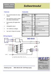
3.2 Typical system structure<br />
W.E.ST. Elektronik GmbH<br />
This minimal system consists of the following components:<br />
(*1) Proportional valve: the valve type determines the precision. It is expedient to use control valves<br />
with integrated electronics.<br />
(*2) Hydraulic cylinder<br />
(*3) Integrated analogue position sensor (alternatively also with external measurement system)<br />
(*4) <strong>POS</strong>-<strong>122</strong>-A or <strong>POS</strong>-<strong>122</strong>-P control module<br />
(*5) Interface to PLC with analogue and digital signals<br />
Page 10 of 36 <strong>POS</strong>-<strong>122</strong>-*-<strong>1113</strong> 06.06.2012
3.3 Method of operation<br />
W.E.ST. Elektronik GmbH<br />
This module supports the simple point-to-point positioning with hydraulic drives. The system works with the<br />
principle of stroke depended deceleration, that means the control gain will be adjusted with the parameters<br />
D:A and D:B.<br />
The deceleration characteristics can be defined with the parameter CTRL linear (LIN) or nearly square root<br />
(SQRT1). By use of standard proportional valves, SQRT1 has to be chosen normally.<br />
By use of control valves with linear characteristics, it depends on the application. If you choice LIN, a<br />
shorter deceleration stroke can be set (D:A and D:B).<br />
Sequence of the positioning:<br />
The positioning procedure is controlled by the switching inputs. After the release (ENABLE) is applied the<br />
required position is set the same as the actual position in the module and the drive remains stationary under<br />
control at the current position. In AUTO mode the module is taking over the selected position (SEL1,<br />
SEl2 and SEL4) and speed after a signal change (START = low to high) or direcly depending on the parameter<br />
DSEL. The drive moves directly to the new required position and reports reaching the position via<br />
the InPos output.<br />
In manual mode (START disabled) the drive can be moved by means of HAND+ or HAND–. The drive<br />
moves under open-loop control at the programmed manual speeds. The InPos signal is active during manual<br />
movement. When the HAND (+ or -) signal is switched off, the current actual position is accepted as the<br />
required position and the drive comes to a controlled stop.<br />
Weak points of positioning accuracy:<br />
Influences on positioning accuracy:<br />
The positioning accuracy is determined by the hydraulic and mechanical conditions. The right choice of<br />
valve is therefore a decisive factor. In addition, two mutually contradictory requirements (short position time<br />
and high accuracy) must be taken into account when designing the system.<br />
The electronic limitations lie mainly in the resolution of the analogue signals, although with our modules a<br />
resolution of < 0.01% only needs to be considered with long positions. In addition, the linearity of the individual<br />
signal points (PLC, sensor and control module) must be considered. The worst-case scenario is that<br />
a system-specific absolute fault occurs.<br />
The repeat accuracy is, however, not affected by this.<br />
V+<br />
V+<br />
A:A D:A<br />
D:B<br />
volumetric flow P-A and B-T<br />
MAX:A<br />
control direction<br />
driving out<br />
control direction<br />
driving in<br />
MAX:B<br />
Page 11 of 36 <strong>POS</strong>-<strong>122</strong>-*-<strong>1113</strong> 06.06.2012<br />
A:B
3.4 Commissioning<br />
Step Task<br />
W.E.ST. Elektronik GmbH<br />
Installation Install the device in accordance with the circuit diagram. Ensure it is wired<br />
correctly and that the signals are well shielded. The device must be installed in a<br />
metal protective housing (control cabinet or similar).<br />
Switching on for the first<br />
time<br />
Ensure that no unwanted movement is possible in the drive (e. g. switch off the<br />
hydraulics). Connect an ammeter and check the current consumed by the device.<br />
If it is higher than specified there is an error in the cabling. Switch the device off<br />
immediately and check the cabling.<br />
Setting up communication Once the power input is correct the PC (notebook) should be connected to the<br />
serial interface. Please see the WPC-300 program documentation for how to set<br />
up communication.<br />
Further commissioning and diagnosis are supported by the operating software.<br />
Pre-parameterization Now set up the following parameters (with reference to the system design and<br />
circuit diagrams):<br />
The command values S:x with corresponding speed values VC:x, POLARITY,<br />
ACCELERATION and DECELERATION. Parameterize specific settings for the<br />
control element (MIN for deadzone compensation and MAX for maximum<br />
velocity).<br />
Pre-parameterization is necessary to minimize the risk of uncontrolled<br />
movements.<br />
Control signal Check the control signal with a voltmeter. The control signal (PIN 15 to PIN16) lies<br />
in the range of ± 10 V. In the current state it should be 0 V. Alternatively, if current<br />
signals are used, approx. 0 mA should flow.<br />
Switching on the<br />
hydraulics<br />
Activating ENABLE<br />
The hydraulics can now be switched on. Since the module is not yet generating a<br />
signal the drive should be at a standstill or drift slightly (leave its position at a slow<br />
speed).<br />
CAUTION! The drive can now leave its position and move to an end position at<br />
full speed. Take safety measures to prevent personal injury and damage.<br />
The drive stays in the current position (with ENABLE the actual position is<br />
accepted as the required position). If the drive moves to an end position, the<br />
polarity is probably wrong.<br />
Manual (HAND) operation If START is disabled the axis can be moved manually with HAND+ or HAND-.<br />
After disabling the HAND signal, the axis stops in a controlled manner at the<br />
current position.<br />
Activating START With the start signal the demand value chosen by the digital switching inputs is<br />
accepted and the axis moves to the predefined target position.<br />
If START is disabled, the axis stops in the preset deceleration distance D:S.<br />
Optimize controller Now optimize the controller parameters according to your application and your<br />
requirements.<br />
Page 12 of 36 <strong>POS</strong>-<strong>122</strong>-*-<strong>1113</strong> 06.06.2012
4 Technical description<br />
4.1 Input and output signals<br />
Connection Supply<br />
W.E.ST. Elektronik GmbH<br />
PIN 3 Power supply (see technical data)<br />
PIN 4 0 V (GND) connection.<br />
Connection Analogue signals<br />
PIN 9/10 Analogue position actual value (X), range 0… 100% corresponds to 0… 10V<br />
PIN 11/12 Potential for analogue feedback and command signals.<br />
PIN 15/16 A Version: Differential output (U) ± 100 % corresponds to ± 10 V (0… 10 V at PIN 15 and<br />
PIN 16). I Version: ± 100 % corresponds to 4… 20 mA (PIN 15 to PIN 12).<br />
12 mA is the neutral position (0 % output signal).<br />
< 4 mA indicates that there is an error and the module has not been enabled. It must be<br />
ensured that the valve switches off at < 4 mA.<br />
Connection Digital inputs and outputs<br />
PIN 8<br />
PIN 7<br />
Enable input:<br />
This digital input signal initializes the application and error messages are deleted. The<br />
controller and the READY signal are activated. The output signal to the control element is<br />
enabled.<br />
The actual position is accepted as the command position and the drive remains stationary<br />
under control at this position.<br />
START (RUN) input:<br />
PIN 5 Auto/Hand- input:<br />
The position controller is active and the external analogue demand position is accepted as<br />
the demand value. If the input is disabled during the movement, the system is stopped<br />
within the set emergency stopping distance (D:S).<br />
Activated = Automatic mode, deactivated = hand mode.<br />
PIN 6 Sel 1 / HAND+ input:<br />
a) Selection input 1<br />
b) Hand mode (START = OFF), The axis drives with the programmed speed (parameter<br />
HAND:A). After the deactivation the command position is set to the actual<br />
position.<br />
PIN 13 Sel 2 / HAND- input:<br />
a) Selection input 2<br />
PIN 14 Sel 4 input:<br />
PIN 1<br />
PIN 2<br />
b) Hand mode (START = OFF), The axis drives with the programmed speed (parameter<br />
HAND:B). After the deactivation the command position is set to the actual<br />
position.<br />
a) Selection input 4<br />
READY output:<br />
ON: The module is enabled; there are no discernable errors.<br />
OFF: Enable (PIN 8) is disabled or an error has been detected.<br />
STATUS output:<br />
ON: IN<strong>POS</strong> message. The axis is within the IN<strong>POS</strong> window.<br />
OFF: IN<strong>POS</strong> message. The axis is outside the IN<strong>POS</strong> window.<br />
Page 13 of 36 <strong>POS</strong>-<strong>122</strong>-*-<strong>1113</strong> 06.06.2012
4.2 LED definitions<br />
W.E.ST. Elektronik GmbH<br />
LEDs Description of the LED function<br />
GREEN Identical to the READY output.<br />
OFF: no power supply or ENABLE is not activated<br />
ON: System is ready for operation<br />
Flashing: Error discovered.<br />
Only active when SENS = ON.<br />
YELLOW Identical to the STATUS output.<br />
OFF: The axis is outside the IN<strong>POS</strong> window.<br />
ON: The axis is within the IN<strong>POS</strong> window.<br />
Page 14 of 36 <strong>POS</strong>-<strong>122</strong>-*-<strong>1113</strong> 06.06.2012
4.3 Circuit diagram<br />
<strong>POS</strong>-<strong>122</strong>A<br />
3,5 mm JISC-6560 Buchse<br />
12 V<br />
5 V<br />
3<br />
DC<br />
24 V<br />
24V<br />
RS232 C<br />
9600 Baud<br />
DC<br />
4<br />
0 V<br />
0V<br />
W.E.ST. Elektronik GmbH<br />
power supply<br />
offset x <br />
x = -1000.. 1000<br />
valve adaption<br />
differential input<br />
of actuator<br />
min:i x <br />
i = A|B<br />
x = 0..5000<br />
acceleration A<br />
ramp A<br />
15<br />
Output: A (0..10)V<br />
a:i x <br />
i = A<br />
x = 1..2000 ms<br />
d:i x <br />
i = A<br />
x = 50..10000<br />
x xw<br />
10<br />
9<br />
0..10V<br />
Feedback position<br />
+<br />
-<br />
u<br />
16<br />
max:i x <br />
i = A|B<br />
x = 5000..10000<br />
11<br />
0 V<br />
0 V<br />
Page 15 of 36 <strong>POS</strong>-<strong>122</strong>-*-<strong>1113</strong> 06.06.2012<br />
Output: B (0..10)V<br />
trigger x <br />
x = 0..2000<br />
a:i x <br />
i = B<br />
x = 1..2000 ms<br />
d:i x <br />
i = B<br />
x = 50..10000<br />
12<br />
command value storage<br />
pol x <br />
x = +|-<br />
acceleration B<br />
ramp B<br />
24 V in<br />
6<br />
Sel 1 / Hand+<br />
I version: 4... 20 mA output<br />
PIN 15 = +, PIN 12 = GND<br />
w<br />
(Pos.)<br />
(Vel.)<br />
s:i x <br />
v:i x <br />
i = 0..7<br />
x = 0..10000<br />
24 V in<br />
13<br />
Sel 2 / Hand-<br />
24 V in<br />
14<br />
Sel 4<br />
general commands<br />
Ready<br />
1<br />
24 V out<br />
Control program<br />
InPos<br />
2<br />
24 V out<br />
24 V in<br />
5<br />
Auto / Hand<br />
24 V in<br />
7<br />
Start/Run<br />
PE by mounting rail<br />
CONFIGURATION<br />
dsel:x (ON|OFF)<br />
hand:i x (i = A|B, x = -10000..10000)<br />
inpos x (x = 0..2000)<br />
trigger x (x = 0..2000)<br />
ctrl x (x = LIN|SQRT1|SQRT2)<br />
DIAGNOSTICS<br />
din <br />
x, w <br />
xw, u <br />
v <br />
SUPPORT<br />
save <br />
loadback <br />
help <br />
para <br />
24 V in<br />
8<br />
Enable
4.4 Typical cabling<br />
PLC inputs<br />
PLC outputs<br />
Analogue position<br />
feedback (0..10V)<br />
PLC outputs<br />
InPos<br />
Ready<br />
W.E.ST. Elektronik GmbH<br />
Enable<br />
Start / S-Valid<br />
Sel 1 / Hand+<br />
Auto/Hand<br />
0 V<br />
0..10V<br />
Sel 2 / Hand-<br />
Sel 4<br />
PE clip<br />
1<br />
5<br />
9<br />
13<br />
Page 16 of 36 <strong>POS</strong>-<strong>122</strong>-*-<strong>1113</strong> 06.06.2012<br />
2<br />
6<br />
10<br />
14<br />
0V<br />
3<br />
7<br />
11<br />
15<br />
4<br />
8<br />
12<br />
16<br />
PE clip<br />
0V<br />
0..10V<br />
0..10V<br />
To power amplifier /<br />
valve. Use differential input.<br />
shield<br />
24V<br />
0V<br />
power supply<br />
(-10V..10V)
4.5 Technical data<br />
Supply voltage<br />
Current requirement<br />
External protection<br />
Digital inputs<br />
Input resistance<br />
W.E.ST. Elektronik GmbH<br />
[VDC]<br />
[mA]<br />
[A]<br />
[V]<br />
[V]<br />
[kOhm]<br />
Digital outputs [V]<br />
Analogue inputs<br />
Signal resolution<br />
Analogue outputs<br />
Voltage<br />
Signal resolution<br />
Current<br />
Signal resolution<br />
[V]<br />
[V]<br />
[%]<br />
[V]<br />
[mA]<br />
[%]<br />
[mA]<br />
[%]<br />
12… 30 (incl. ripple)<br />
Page 17 of 36 <strong>POS</strong>-<strong>122</strong>-*-<strong>1113</strong> 06.06.2012<br />
5 Parameters<br />
5.1 Parameter overview<br />
W.E.ST. Elektronik GmbH<br />
Command Default Unit Description<br />
S:I 0 0,01 % Presetting the command positions selectable by the binary coded digital<br />
inputs SEL 1, 2 and 4.<br />
VC:I 5000 0,01 % Presetting the command velocity selectable by the binary coded digital<br />
inputs SEL 1, 2 and 4.<br />
DSEL OFF - Mode of command value activation.<br />
A:A<br />
A:B<br />
D:A<br />
D:B<br />
100<br />
100<br />
2500<br />
2500<br />
ms<br />
ms<br />
0,01 %<br />
0,01 %<br />
Acceleration time for each direction.<br />
Deceleration stroke for each direction.<br />
CTRL SQRT1 - Selection of the control function.<br />
VMODE OFF - Activation of the NC-generator.<br />
TH 5000 ms Stroke time for 100% velocity and 100% nominal sensor stroke.<br />
HAND:A<br />
HAND:B<br />
MIN:A<br />
MIN:B<br />
MAX:A<br />
MAX:B<br />
3330<br />
-3330<br />
0<br />
0<br />
10000<br />
10000<br />
0,01 %<br />
0,01 %<br />
0,01 %<br />
0,01 %<br />
0,01 %<br />
0,01 %<br />
Output signal in manual mode.<br />
Zero point setting /following error compensation.<br />
Maximum output signal limitation.<br />
TRIGGER 200 0,01 % Trigger threshold for activating the following error compensation (MIN).<br />
IN<strong>POS</strong> 200 0,01 % Range for InPos signal.<br />
OFFSET 0 0,01 % Offset value (added to the output signal).<br />
POL + - Changing the polarity of the output signal.<br />
SENS ON - Activation and deactication of the internal monitoring functions.<br />
DIN - - Displays status of the digital inputs.<br />
Page 18 of 36 <strong>POS</strong>-<strong>122</strong>-*-<strong>1113</strong> 06.06.2012
5.2 Parameter description<br />
W.E.ST. Elektronik GmbH<br />
5.2.1 S (Presetting command values)<br />
Command Parameters Unit Group<br />
S:I X I= 0… 7<br />
x= 0… 10000<br />
0,01%<br />
With these parameters eight different command values can be preset.<br />
Via the inputs SEL 1, SEL 2, and SEL 4 at PIN 6, 13 and 14 the value is chosen by binary coding.<br />
By activating these inputs with logical high signal the following values can be selected:<br />
Speicherstelle 0 1 2 3 4 5 6 7<br />
Eingang SEL 1 0 1 0 1 0 1 0 1<br />
Eingang SEL 2 0 0 1 1 0 0 1 1<br />
Eingang SEL 4 0 0 0 0 1 1 1 1<br />
5.2.2 VC (Presetting velocities)<br />
Command Parameters Unit Group<br />
VC:I X I= 0… 7<br />
x= 0… 10000<br />
0,01 %<br />
These parameters are the corresponding velocities to the chosen command value. Each target position will<br />
be driven to with it’s own maximum speed. For example: if S:1 is selected via the digital inputs command<br />
the related speed of VC:1 is also selected by this choice.<br />
Page 19 of 36 <strong>POS</strong>-<strong>122</strong>-*-<strong>1113</strong> 06.06.2012
W.E.ST. Elektronik GmbH<br />
5.2.3 DSEL (Deactivation of the S-VALID)<br />
Command Parameters Unit Group<br />
DSEL x x= ON|OFF -<br />
This command changes the way of activation of new command values.<br />
DSEL = OFF: A new target position is taken over by setting S-VALID (PIN 7) from low to high.<br />
DSEL = ON: A new target position is taken over directly while START (PIN 7) is on high level.<br />
5.2.4 A (Acceleration time)<br />
Ramp function in ms.<br />
Command Parameters Unit Group<br />
A:I X i= A|B<br />
x= 1… 2000<br />
The acceleration time for positioning is set for each direction (drive out:A / drive in:B).<br />
Normally A = flow P-A, B-T and B = flow P-B, A-T.<br />
5.2.5 D (Deceleration /braking distance)<br />
Command Parameters Unit Group<br />
D:I X i= A|B<br />
x= 50… 10000<br />
Page 20 of 36 <strong>POS</strong>-<strong>122</strong>-*-<strong>1113</strong> 06.06.2012<br />
ms<br />
ms<br />
0,01 %<br />
0,01 %<br />
This parameter is specified in 0,01%.<br />
The deceleration stroke is set for each direction of movement (A or B, quadrants 2 and 4). The control gain<br />
is calculated internally depending on the deceleration distance. The shorter the deceleration distance, the<br />
higher the gain (see CTRL). A longer deceleration distance should be specified in the event of instability.
W.E.ST. Elektronik GmbH<br />
5.2.6 CTRL (Deceleration function characteristic)<br />
Command Parameters Unit Group<br />
CTRL X x= lin|sqrt1<br />
|sqrt2<br />
- STD<br />
The deceleration characteristic is set with this parameter. In case of positively overlapped proportional<br />
valves the SQRT function should be used. The non-linear flow function of these valves is linearized by the<br />
SQRT 2 function.<br />
In case of zero lapped valves (control valves and servo valves) the LIN or SQRT1 function should be used<br />
regardless of the application. The progressive characteristic of the SQRT1 function has better positioning<br />
accuracy but can also lead to longer positioning times in individual cases.<br />
LIN: Linear deceleration characteristic (gain is increased by a factor of 1).<br />
SQRT1: Root function for braking curve calculation. The gain is increased by a factor of 3 (in the target<br />
position). This is the default setting.<br />
SQRT2: Root function for braking curve calculation. The gain is increased by a factor of 5 (in the target<br />
position). This setting should only be used with a significantly progressive flow through the<br />
valve.<br />
Velocity<br />
CTRL = LIN<br />
Braking stroke<br />
D:A or D:B<br />
Stroke<br />
CTRL = SQRT<br />
2 The SQRT function generates constant deceleration and thus reaches the target position faster. This is achieved by<br />
increasing the gain during the deceleration process.<br />
Velocity<br />
CTRL = LIN<br />
1 Braking function with respect to stroke and time<br />
Deceleration time<br />
D:A or D:B<br />
CTRL = SQRT<br />
Page 21 of 36 <strong>POS</strong>-<strong>122</strong>-*-<strong>1113</strong> 06.06.2012<br />
Time
W.E.ST. Elektronik GmbH<br />
5.2.7 VMODE (Switching over the control mode)<br />
Command Parameters Unit Group<br />
VMODE X x= ON|OFF<br />
With this parameter the NC mode (almost closed loop controlled velocity) will be activated. In OFF state the<br />
stroke depended deceleration is active; the velocity preset limits the output signal.<br />
In ON state the positioning demand value is generated by a profile generator and the axis drives to the target<br />
position with the defined velocity. The stroke time is defined by the parameter th.<br />
5.2.8 TH (Stroke time for speed controlled axis )<br />
Command Parameters Unit Group<br />
TH X x= 100… 60000 ms<br />
The stroke time is defined for the stroke of 100 %. It is also defined for 100 % velocity.<br />
5.2.9 HAND (Manual speed)<br />
Command Parameters Unit Group<br />
HAND:I X i= A|B<br />
x= -10000… 10000<br />
0,01%<br />
0,01%<br />
The manual speeds are set with these parameters. The drive moves in a controlled manner in the defined<br />
direction when the manual signal is active. After the manual signal has been disabled, the drive remains<br />
under control in the current position.<br />
Page 22 of 36 <strong>POS</strong>-<strong>122</strong>-*-<strong>1113</strong> 06.06.2012
W.E.ST. Elektronik GmbH<br />
5.2.10 MIN (Deadband compensation)<br />
5.2.11 MAX (Limitation / Gain )<br />
5.2.12 TRIGGER (Response threshold for the MIN parameter)<br />
Command Parameters Unit Group<br />
MIN:I X<br />
MAX:I X<br />
TRIGGER X<br />
i= A|B<br />
x= 0… 6000<br />
x= 3000… 10000<br />
x= 0… 4000<br />
Page 23 of 36 <strong>POS</strong>-<strong>122</strong>-*-<strong>1113</strong> 06.06.2012<br />
-<br />
0,01 %<br />
0,01 %<br />
0,01 %<br />
The output signal to the valve is adjusted by means of these commands. A kinked volume flow<br />
characteristic is used instead of the typical overlap step for the position controls. The advantage is better<br />
and more stable positioning behavior. At the same time, kinked volume flow characteristics can also be<br />
adjusted with this compensation 3 .<br />
CAUTION: If there should also be adjustment options for deadband compensation on the<br />
valve or valve amplifier, it must be ensured that the adjustment is performed either at the<br />
power amplifier or in the module.<br />
If the MIN value is set too high this has an effect on the minimum speed, which can then<br />
no longer be adjusted. In extreme cases this leads to oscillation around the controlled<br />
position.<br />
MIN:B<br />
MAX:B<br />
Ausgang<br />
geknickte Volumenstromkennlinie<br />
normale Überdeckungskompensation<br />
TRIGGER Werte<br />
Eingang<br />
3 Various manufacturers have valves with a defined non linear curve: e.g. a kink at 40 or 60 % (corresponding to 10 %<br />
input signal) of the nominal volume flow. In this case the TRIGGER value should be set to 1000 and the MIN value to<br />
4000 (6000).<br />
If zero lapped or slightly underlapped valves are used, the volume flow gain in the zero range (within the underlap) is<br />
twice as high as in the normal working range. This can lead to vibrations and jittery behaviour. To compensate this, the<br />
TRIGGER value should be set to approximately 200 and the MIN value to 100. The gain in the zero point is thus halved<br />
and a higher overall gain can often be set.<br />
MAX:A<br />
MIN:A
5.2.13 IN<strong>POS</strong> (In position window)<br />
W.E.ST. Elektronik GmbH<br />
Command Parameters Unit Group<br />
IN<strong>POS</strong> X x= 0… 2000 0,01 %<br />
This parameter is entered in 0,01 %.<br />
The IN<strong>POS</strong> command defines a monitoring window in which the IN<strong>POS</strong> message is displayed. The<br />
monitoring window is placed centrally on the required position value. The actual position value within this<br />
window is signalled by the IN<strong>POS</strong> message at the status output (see Pin description). The positioning<br />
process is not influenced by this message. The control function remains active.<br />
In NC Mode this message is used to monitor the following error (depending on the parameterization).<br />
5.2.14 OFFSET (Zero correction)<br />
Command Parameters Unit Group<br />
OFFSET X<br />
x= -2000… 2000 0,01 %<br />
This parameter is entered in 0,01 % units.The offset value is added to the output value. Valve zero offsets<br />
can be compensated with this parameter.<br />
5.2.15 POL (Output polarity)<br />
Command Parameters Unit Group<br />
POL X x= +|- -<br />
This command enables the output signal polarity to be reversed.<br />
Page 24 of 36 <strong>POS</strong>-<strong>122</strong>-*-<strong>1113</strong> 06.06.2012
5.2.16 SENS (Module monitoring)<br />
W.E.ST. Elektronik GmbH<br />
Command Parameters Unit Group<br />
SENS x x= ON|OFF -<br />
This command is used to activate/deactivate the monitoring functions (output current and internal failures)<br />
of the module.<br />
OFF: No monitoring function is active.<br />
ON: All monitoring functions are active. Detected failures can be reset by deactivating the ENABLE<br />
input.<br />
Normally the monitoring functions are always active(ON or AUTO mode) because otherwise no<br />
errors are detectable via the READY output. Deactivating is possible mainly for troubleshooting.<br />
5.2.17 DIN (Input status)<br />
Command Parameters Unit Group<br />
DIN - -<br />
This command displays the status of the digital inputs. So you can monitor the status of the system and the<br />
selected command value.<br />
5.2.18 PROCESS DATA (Monitoring)<br />
Command Parameters Unit<br />
W<br />
X<br />
XW<br />
V<br />
U<br />
Demand value<br />
Actual value<br />
Error variable<br />
Speed demand<br />
Control signal<br />
The process data are the variables which can be observed continuously on the monitor or on the<br />
oscilloscope.<br />
Page 25 of 36 <strong>POS</strong>-<strong>122</strong>-*-<strong>1113</strong> 06.06.2012<br />
mm<br />
mm<br />
mm<br />
%<br />
%
6 Appendix<br />
6.1 Failure monitoring<br />
W.E.ST. Elektronik GmbH<br />
Following possible error sources are monitored continuously:<br />
Source Fault Characteristic<br />
P-VERSION<br />
Solenoid A on PIN 17/19 and<br />
Solenoid B on PIN 18/20<br />
EEPROM<br />
(at switching on)<br />
6.2 Troubleshooting<br />
Wrong cabling, broken wire.<br />
The power stage gets deactivated.<br />
Data error The output is deactivated.<br />
The module can be activated by<br />
saving new parameters (pressing of<br />
the SAVE Button).<br />
It is assumed that the device is in an operable state and there is communication between the module and<br />
the WPC-300. Furthermore, the valve control parameterization has been set with the assistance of the<br />
valve data sheets.<br />
FAULT CAUSE / SOLUTION<br />
ENABLE is active, the<br />
module does not<br />
respond, and the<br />
READY LED is off.<br />
ENABLE is active, the<br />
READY LED is flashing.<br />
ENABLE is active; the<br />
READY LED is on, the<br />
system moves to an<br />
end position.<br />
There is presumably no power supply or the ENABLE signal (PIN 8) is not present.<br />
If there is no power supply there is also no communication via our operating<br />
program. If a connection has been made to the WPC-300, then a power supply is<br />
also available.<br />
If the power supply exists, an attempt should be made to see whether the system<br />
can be moved by means of the HAND+ and HAND- inputs (measuring the output<br />
signal to the valve helps).<br />
The flashing READY LED signals that a fault is been detected by the module. The<br />
fault could be:<br />
• A broken cable or incorrect cabling to the solenoids (in the P version only).<br />
• Internal data error: press the command/SAVE button to delete the data<br />
error. The system reloads the DEFAULT data.<br />
The control circuit polarity is incorrect. The polarity can be changed with the POL<br />
command or by reversing the connections to PIN 15 and PIN 16.<br />
Page 26 of 36 <strong>POS</strong>-<strong>122</strong>-*-<strong>1113</strong> 06.06.2012
ENABLE is active, the<br />
READY LED is on, the<br />
STATUS LED is not on,<br />
the system moves to<br />
the target position but<br />
doesn’t reach it<br />
(positioning error).<br />
ENABLE is active, the<br />
READY LED is on, and<br />
the system oscillates on<br />
the target.<br />
W.E.ST. Elektronik GmbH<br />
Serious positioning errors can result from incorrect parameterization or incorrect<br />
system design.<br />
• Is the cylinder position specified correctly?<br />
• Are the deceleration strokes correct (to start the system the deceleration<br />
distances should be set to approx. 20… 25 % of the cylinder position 4 )?<br />
• Is the valve a zero lapped control valve or a standard proportional valve?<br />
In the case of a proportional valve, the valve overlap which may be present<br />
should be compensated for with the MIN parameters. Typical values are to<br />
be found in the valve data sheet.<br />
The system is working and also actuating the valve.<br />
Various potential problems could be:<br />
• The parameterization is not yet adjusted to the system (gain too high).<br />
• There is severe interference on the power supply.<br />
• Very long sensor cables (> 40 m) and sensor signal interference.<br />
• The MIN setting to compensate the valve overlap is too high.<br />
As a basic principle, the parameterization of the sensor data and the controller<br />
settings must be carried out first (before switching on). An incorrect demand is<br />
equivalent to incorrect system design which then leads to incorrect operation. If the<br />
system oscillates, the gain should first be reduced (longer deceleration distances for<br />
D:A and D:B) and in the case of overlapped valves the MIN parameter should also<br />
be reduced.<br />
Speed too low The drive may be able to move to position but the speed is too low.<br />
• Check the control signal to the valve.<br />
• Via the integrated oscilloscope (U variable).<br />
• Measure the signal to the valve with an external oscilloscope /<br />
voltmeter.<br />
• If the control is within the range of ± 100 % (± 10 V), the fault must be<br />
sought in the hydraulics.<br />
• If the control signal is relatively low, the following points should be checked:<br />
• Is the internal/external speed signal limiting the speed?<br />
• Which setting has been specified for the deceleration distance in<br />
relation to the <strong>POS</strong>ITION?<br />
Speed too high The drive should move to position. The drive moves in and out too fast leading to<br />
uncontrolled behaviour. Reducing the speed (MAX or VC parameter) has very little or<br />
no effect.<br />
• The hydraulic system is over-sized. The entire parameterization of the<br />
movement cycle cannot be reproduced (overlap and deceleration distance<br />
settings)<br />
4 The stability criterion of the hydraulic axes must be taken into account.<br />
Page 27 of 36 <strong>POS</strong>-<strong>122</strong>-*-<strong>1113</strong> 06.06.2012
W.E.ST. Elektronik GmbH<br />
6.3 Description of the command structure<br />
The command structure:<br />
[nnnn:i x] or<br />
[nnnn x]<br />
Meaning:<br />
nnnn - used for an arbitrary command name<br />
nnnn: - used for an arbitrary command name, expandable by an index.<br />
i oder I - a dummy is for the index. E. g. an index can be „A“ or „B“, depending on the direction.<br />
x - parameter value, in case of special commands more than one parameter are possible.<br />
Examples:<br />
MIN:A 2000 nnnn = “MIN”, i = “A” and x = “2000”<br />
OFFSET 50 nnnn = „OFFSET“ and x = „50“<br />
C:IC 2000 nnnn = “C”, i = “IC” and x = “2000”<br />
Page 28 of 36 <strong>POS</strong>-<strong>122</strong>-*-<strong>1113</strong> 06.06.2012
W.E.ST. Elektronik GmbH<br />
7 ADDITIONAL INFORMATION: Power output stage<br />
7.1 General function<br />
The power output stages have been developed for controlling proportional valves without spool position<br />
feedback. The output stage is controlled by the microcontroller on the basic module by means of pulse<br />
width modulated signals, and the current is continuously controlled. The cycle time for the controller is<br />
0,167 ms.<br />
The output stage can be ideally adjusted to dynamic requirements via internal parameters.<br />
Valve technology: Directional, throttle, pressure and flow control valves manufactured by REXROTH,<br />
BOSCH, DENISON, EATON, PARKER, FLUID TEAM, ATOS and others.<br />
Features<br />
• Two power output stages for 1A, 1,6A und 2,6A<br />
• Hardware short-circuit protection with 3 µs response time<br />
• Adjustable PWM frequency, dither frequency and dither amplitude<br />
• High current signal resolution<br />
• Optionally for directional, throttle control or for pressure valves<br />
• Separate power supply for safety-relevant applications<br />
• Integrated into the standard controller, no additional cabling necessary<br />
• Optimum price/performance ratio<br />
Page 29 of 36 <strong>POS</strong>-<strong>122</strong>-*-<strong>1113</strong> 06.06.2012
7.2 Device description<br />
99,0000 mm<br />
Made in Germany<br />
Date: Add.:<br />
ID:<br />
V:<br />
W.E.ST. Elektronik<br />
D-41372 Niederkrüchten<br />
Homepage: http://www.w-e-st.de<br />
Typenschild und Anschlussbelegung<br />
Type plate and terminal pin assignment<br />
W.E.ST. Elektronik GmbH<br />
LEDs<br />
RS232C<br />
Interface<br />
9 10 11 12<br />
25 26 27 28<br />
13 14 15 16 29 30 31 32<br />
1 2 3 4<br />
5 6 7 8<br />
W.E.ST.<br />
Ready<br />
Status<br />
9 10 11 12<br />
17 18 19 20<br />
21 22 23 24<br />
25 26 27 28<br />
13 14 15 16 29 30 31 32<br />
45,0000 mm<br />
114,0000 mm<br />
Klemmblöcke (steckbar)<br />
Terminals (removable)<br />
Page 30 of 36 <strong>POS</strong>-<strong>122</strong>-*-<strong>1113</strong> 06.06.2012
7.3 Inputs and outputs<br />
Connection Signal description<br />
PIN 22 +<br />
PIN 24 -<br />
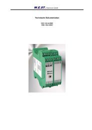
7.4 Circuit diagram<br />
W.E.ST. Elektronik GmbH<br />
Power supply: 10… 30 VDC: For safety-related applications, the output stage<br />
can be deactivated thanks to the separate power supply inputs.<br />
PIN 17+19 Solenoid current output A<br />
PIN 18+20 Solenoid current output B<br />
Connection Signals modified from the standard (A and I version)<br />
PIN 15 0… 10 V output with the scaled position demand value<br />
PIN 16 0… 10 V output with the scaled position feedback value<br />
10..30V<br />
0V<br />
Power supply<br />
24 V<br />
0 V<br />
22<br />
24<br />
Internal MCU<br />
interface<br />
Power output stage<br />
Page 31 of 36 <strong>POS</strong>-<strong>122</strong>-*-<strong>1113</strong> 06.06.2012<br />
ia<br />
ib<br />
17<br />
19<br />
18<br />
20<br />
17<br />
19<br />
20<br />
18<br />
Solenoid A<br />
Solenoid B<br />
for expample:<br />
HAWE valves
7.5 Typical cabling<br />
7.6 Technical data<br />
W.E.ST. Elektronik GmbH<br />
CAUTION: The solenoid cables should be screened due to electro-magnetic emissions.<br />
CAUTION: plugs with free-wheeling diodes and LED indicators cannot be used with<br />
current-controlled power outputs. They interfere with the current control and can destroy<br />
the output stage.<br />
Supply voltage<br />
Current requirement<br />
Fuse protection<br />
PE Klemme<br />
Output currents (PWM<br />
signal, current-controlled)<br />
Max. solenoid currents<br />
[VDC]<br />
[A]<br />
[A]<br />
[A]<br />
10... 30<br />
Depending on the solenoid type<br />
(max. 5 A)<br />
5 (medium time lag)<br />
1,0 / 1,6 / 2,6 selectable via<br />
software<br />
Housing Snap-on module EN 50022<br />
Temperature range [°C] -20… 60<br />
Weight [kg] 0,250<br />
1<br />
5<br />
9<br />
13<br />
0V<br />
2<br />
6<br />
10<br />
14<br />
3<br />
7<br />
11<br />
15<br />
Polyamide PA 6.6<br />
Flammability class V0 (UL94)<br />
Connections 2 x 4-pole terminal blocks<br />
4<br />
8<br />
12<br />
16<br />
17<br />
21<br />
25<br />
29<br />
Page 32 of 36 <strong>POS</strong>-<strong>122</strong>-*-<strong>1113</strong> 06.06.2012<br />
18<br />
22<br />
26<br />
30<br />
19<br />
23<br />
27<br />
31<br />
20<br />
24<br />
28<br />
32<br />
PE Klemme<br />
24V<br />
0V<br />
Power supply<br />
Solenoid A<br />
Solenoid B
7.7 Parameters<br />
7.7.1 Parameter overview<br />
W.E.ST. Elektronik GmbH<br />
Command Default Unit Description<br />
CURRENT 0 - Switching over the output current.<br />
DFREQ 120 Hz Dither frequency<br />
DAMPL 600 0,01 % Dither amplitude.<br />
PWM 2600 Hz PWM frequency<br />
PPWM<br />
IPWM<br />
7<br />
40<br />
-<br />
-<br />
Current control loop PI control dynamics.<br />
The standard parameterization has been used with a large number of proportional vales from various<br />
manufacturers. This parameterization has proved to be good as long as no special demands are made of<br />
the application.<br />
7.8 Parameter description<br />
7.8.1 CURRENT (Current range switchover)<br />
Command Parameters Unit Group<br />
CURRENT X x= 0, 1 und 2 - STD<br />
The nominal current range is set with this parameter. Dither and also MIN/MAX always refer to the selected<br />
current range.<br />
0 = 1,0 A range, 1 = 1,6 A range and 2 = 2,6 A range.<br />
7.8.2 DFREQ (Dither frequency)<br />
7.8.3 DAMPL (Dither amplitude)<br />
Command Parameters Unit Group<br />
DFREQ X x= 60… 400 Hz STD<br />
DAMPL X x= 0… 3000 0,01 % STD<br />
The dither can be defined with this command. Different amplitudes or frequencies may be required<br />
depending on the valve.<br />
CAUTION: The PPWM and IPWM parameters influence the effect of the dither setting. These<br />
parameters should not be altered again after the dither has been optimized.<br />
CAUTION: If the PWM frequency is less than 500 Hz the dither amplitude DAMPL should be set<br />
to zero.<br />
Page 33 of 36 <strong>POS</strong>-<strong>122</strong>-*-<strong>1113</strong> 06.06.2012
7.8.4 PWM (PWM frequency)<br />
W.E.ST. Elektronik GmbH<br />
Command Parameters Unit Group<br />
PWM X x= 100… 7700 Hz STD<br />
This parameter is entered in Hz. The optimum frequency depends on the valve.<br />
CAUTION: the PPWM and PPWM parameters should be adjusted with low PWM frequencies.<br />
The PWM frequency can only be set in defined steps. This means that there are deviations<br />
between the specified and the actual frequency. The next highest frequency step is always used.<br />
7.8.5 PPWM (Solenoid current controller P element)<br />
7.8.6 IPWM (Solenoid current controller I element)<br />
Command Parameters Unit Group<br />
PPWM X<br />
IPWM X<br />
x= 0… 30<br />
x= 4… 100<br />
The PI current controllers for the solenoids are parameterized with these commands 5 .<br />
Page 34 of 36 <strong>POS</strong>-<strong>122</strong>-*-<strong>1113</strong> 06.06.2012<br />
-<br />
-<br />
CAUTION: These parameters should not be changed without appropriate measurement<br />
capabilities and experience.<br />
If the PWM frequency is > 2500 Hz, the dynamic response of the current controller can be increased.<br />
Typical values are: PPWM = 7… 15 and IPWM = 20… 40.<br />
If the PWM frequency is < 250 Hz, the dynamic response of the current controller must be reduced.<br />
Typical values are: PPWM = 1… 3 and IPWM = 40… 80.<br />
5 CAUTION! This setting is dependent on the dynamic response of the solenoid (inductance).<br />
EXP
8 Notes<br />
W.E.ST. Elektronik GmbH<br />
Page 35 of 36 <strong>POS</strong>-<strong>122</strong>-*-<strong>1113</strong> 06.06.2012