PAM-193-*-4021
PAM-193-*-4021
PAM-193-*-4021

You also want an ePaper? Increase the reach of your titles
YUMPU automatically turns print PDFs into web optimized ePapers that Google loves.
W.E.ST. Elektronik GmbH<br />
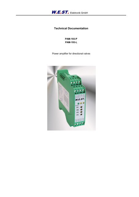
Technical Documentation<br />
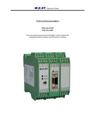
<strong>PAM</strong>-<strong>193</strong>-P<br />
<strong>PAM</strong>-<strong>193</strong>-L<br />
Power amplifier for directional valves
W.E.ST. Elektronik GmbH<br />
CONTENTS<br />
1 General Information ....................................................................................................................................... 3<br />
1.1 Order number ........................................................................................................................................ 3<br />
1.2 Scope of supply ..................................................................................................................................... 3<br />
1.3 Symbols used ........................................................................................................................................ 4<br />
1.4 Legal notice ........................................................................................................................................... 4<br />
1.5 Safety instructions .................................................................................................................................. 5<br />
2 Characteristics .............................................................................................................................................. 6<br />
2.1 Device description .................................................................................................................................. 7<br />
3 Use and application ....................................................................................................................................... 8<br />
3.1 Installation instructions ........................................................................................................................... 8<br />
3.2 Typical system structure ......................................................................................................................... 9<br />
3.3 Method of operation ............................................................................................................................... 9<br />
3.4 Commissioning .................................................................................................................................... 10<br />
4 Technical description ................................................................................................................................... 11<br />
4.1 Input and output signals ....................................................................................................................... 11<br />
4.2 LED definitions..................................................................................................................................... 11<br />
4.3 Circuit diagram..................................................................................................................................... 12<br />
4.4 Typical cabling ..................................................................................................................................... 13<br />
4.5 Technical data ..................................................................................................................................... 14<br />
5 Adjustment elements ................................................................................................................................... 15<br />
5.1 Potentiometer ...................................................................................................................................... 15<br />
5.2 Internal DIL switches ............................................................................................................................ 15<br />
5.3 Start-up ............................................................................................................................................... 16<br />
5.4 General behaviour: .............................................................................................................................. 17<br />
6 Appendix ..................................................................................................................................................... 18<br />
6.1 Failure monitoring ................................................................................................................................ 18<br />
6.2 Troubleshooting ................................................................................................................................... 18<br />
6.3 Replacements / compatibility ................................................................................................................ 19<br />
6.3.1 <strong>PAM</strong>-191 ..................................................................................................................................... 19<br />
6.3.2 <strong>PAM</strong>-192 ..................................................................................................................................... 20<br />
6.3.3 Special versions .......................................................................................................................... 21<br />
7 Notes .......................................................................................................................................................... 22<br />
Page 2 of 23 <strong>PAM</strong>-<strong>193</strong>-*-<strong>4021</strong> 02.08.2012
1 General Information<br />
1.1 Order number<br />
W.E.ST. Elektronik GmbH<br />
<strong>PAM</strong>-<strong>193</strong>-P-<strong>4021</strong> - for single or double solenoid valves (max output current: 1,2 A and 2,6 A)<br />
<strong>PAM</strong>-<strong>193</strong>-L-<strong>4021</strong> - for single or double solenoid valves (max output current: 0,6 A and 1,2 A)<br />
Alternative products<br />
<strong>PAM</strong>-195 - power amplifier for directional valves<br />
<strong>PAM</strong>-192 - power amplifier for control valves, adjustment via potentiometer<br />
1.2 Scope of supply<br />
The scope of supply includes the module plus the terminal blocks which are a part of the housing. The<br />
Profibus plug, interface cables and further parts which may be required should be ordered separately.<br />
This documentation can be downloaded as a PDF file from www.w-e-st.de.<br />
Page 3 of 23 <strong>PAM</strong>-<strong>193</strong>-*-<strong>4021</strong> 02.08.2012
1.3 Symbols used<br />
1.4 Legal notice<br />
General information<br />
Safety-related information<br />
W.E.St. Elektronik GmbH<br />
Gewerbering 31<br />
D-41372 Niederkrüchten<br />
Tel.: +49 (0)2163 577355 - 0<br />
Fax.: +49 (0)2163 577355 - 11<br />
W.E.ST. Elektronik GmbH<br />
Home page: www.w-e-st.de or www.west-electronics.com<br />
EMAIL: info@w-e-st.de<br />
Date: 02.08.2012<br />
The data and characteristics described herein serve only to describe the product. The user is required to<br />
evaluate this data and to check suitability for the particular application. General suitability cannot be<br />
inferred from this document. We reserve the right to make technical modifications due to further<br />
development of the product described in this manual. The technical information and dimensions are nonbinding.<br />
No claims may be made based on them.<br />
This document is copyright.<br />
Page 4 of 23 <strong>PAM</strong>-<strong>193</strong>-*-<strong>4021</strong> 02.08.2012
1.5 Safety instructions<br />
W.E.ST. Elektronik GmbH<br />
Please read this document and the safety instructions carefully. This document will help to define the<br />
product area of application and to put it into operation. Additional documents and knowledge of the application<br />
should be taken into account or be available.<br />
General regulations and laws (depending on the country: e. g. accident prevention and environmental<br />
protection) must be complied with.<br />
These modules are designed for hydraulic applications in open or closed loop control circuits.<br />
Uncontrolled movements can be caused by device defects (in the hydraulic module<br />
or the components), application errors and electrical faults. Work on the drive or the electronics<br />
must only be carried out whilst the equipment is switched off and not under pressure.<br />
This handbook describes the functions and the electrical connections for this electronic<br />
assembly. All technical documents which pertain to the system must be complied with<br />
when commissioning.<br />
This device may only be connected and put into operation by trained specialist staff. The<br />
instruction manual must be read with care. The installation instructions and the commissioning<br />
instructions must be followed. Guarantee and liability claims are invalid if the instructions<br />
are not complied with and/or in case of incorrect installation or inappropriate<br />
use.<br />
CAUTION!<br />
All electronic modules are manufactured to a high quality. Malfunctions due to the failure<br />
of components cannot, however, be excluded. Despite extensive testing the same also<br />
applies for the software. If these devices are deployed in safety-relevant applications,<br />
suitable external measures must be taken to guarantee the necessary safety. The same<br />
applies for faults which affect safety. No liability can be assumed for possible damage.<br />
Further instructions<br />
The module may only be operated in compliance with the national EMC regulations. It<br />
is the user’s responsibility to adhere to these regulations.<br />
The device is only intended for use in the commercial sector.<br />
When not in use the module must be protected from the effects of the weather, contamination<br />
and mechanical damage.<br />
The module may not be used in an explosive environment.<br />
To ensure adequate cooling the ventilation slots must not be covered.<br />
The device must be disposed of in accordance with national statutory provisions.<br />
Page 5 of 23 <strong>PAM</strong>-<strong>193</strong>-*-<strong>4021</strong> 02.08.2012
2 Characteristics<br />
W.E.ST. Elektronik GmbH<br />
This module is used for the control of proportional valves with one or two solenoids. Various adjustable<br />
parameters enable an optimized adaptation to the respective valve. This power amplifier is inexpensive<br />
and a space-saving solution.<br />
The amplifier is controlled by voltage input or current input signals.<br />
The output current is closed loop controlled and therefore independent from the supply voltage and the<br />
solenoid resistance.<br />
Typical applications: Control of proportional valves<br />
Features<br />
Power amplifier for proportional directional valves<br />
Internal controlled by a modern microcontroller<br />
Compact housing<br />
Adjustment via potentiometer<br />
MIN-, MAX-, RAMP- and PWM-frequency adjustment via potentiometer<br />
Current range (per DIL switch): up to 2,6 A<br />
Page 6 of 23 <strong>PAM</strong>-<strong>193</strong>-*-<strong>4021</strong> 02.08.2012
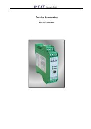
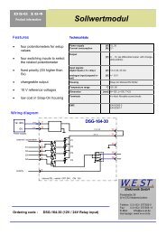
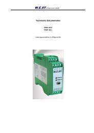
2.1 Device description<br />
Made in Germany<br />
Date: Add.:<br />
ID:<br />
V:<br />
W.E.ST. Elektronik GmbH<br />
99,0000 mm<br />
W.E.ST. Elektronik<br />
D-41372 Niederkrüchten<br />
Homepage: http://www.w-e-st.de<br />
Typenschild und Anschlussbelegung<br />
Type plate and terminal pin assignment<br />
Klemmblöcke (steckbar)<br />
Terminals (removable)<br />
9 10 11 12<br />
13 14 15 16<br />
1 2 3 4<br />
5 6 7 8<br />
W.E.ST.<br />
9 10 11 12<br />
14 15 16<br />
Page 7 of 23 <strong>PAM</strong>-<strong>193</strong>-*-<strong>4021</strong> 02.08.2012<br />
Ready<br />
MINA<br />
MINB<br />
MAXA<br />
MAXB<br />
13<br />
A B<br />
23,0000 mm<br />
114,0000 mm<br />
LEDs<br />
Potentiometer
3 Use and application<br />
3.1 Installation instructions<br />
W.E.ST. Elektronik GmbH<br />
This module is designed for installation in a shielded EMC housing (control cabinet). All cables<br />
which lead outside must be screened; complete screening is required. It is also a requirement<br />
that no strong electro-magnetic interference sources are installed nearby when using our open<br />
and closed loop control modules.<br />
Typical installation location: 24 V control signal area (close to PLC)<br />
The devices must be arranged in the control cabinet so that the power section and the signal section<br />
are separate from each other.<br />
Experience shows that the installation space close to the PLC (24 V area) is most suitable. All<br />
digital and analogue inputs and outputs are fitted with filters and surge protection in the device.<br />
The module should be installed and wired in accordance with the documentation bearing in mind<br />
EMC principles. If other consumers are operated with the same power supply, a star-connected<br />
ground wiring scheme is recommended. The following points must be observed when wiring:<br />
The signal cables must be laid separately from power cables.<br />
Analogue signal cables must be screened.<br />
All other cables must be screened if there are powerful interference sources (frequency<br />
converters, power contactors) and cable lengths > 3 m. Inexpensive SMD ferrites<br />
can be used with high-frequency radiation.<br />
The screening should be connected to PE (PE terminal) as close to the module as<br />
possible. The local requirements for screening must be taken into account in all cases.<br />
The screening should be connected to at both ends. Equipotential bonding must be<br />
provided where there are differences between the connected electrical components.<br />
With longer lengths of cable (>10 m) the diameters and screening measures should<br />
be checked by specialists (e. g. for possible interference, noise sources and voltage<br />
drop). Particular care is required with cables of over 40 m in length – the manufacturer<br />
should be consulted if necessary.<br />
A low-resistance connection between PE and the mounting rail should be provided. Transient interference<br />
is transmitted from the module directly to the mounting rail and from there to the local<br />
earth.<br />
Power should be supplied by a regulated power supply unit (typically a PELV system complying<br />
with IEC364-4-4, secure low voltage). The low internal resistance of regulated power supplies<br />
gives better interference voltage dissipation, which improves the signal quality of high-resolution<br />
sensors in particular. Switched inductances (relays and valve coils) connected to the same power<br />
supply must always be provided with appropriate overvoltage protection directly at the coil.<br />
Page 8 of 23 <strong>PAM</strong>-<strong>193</strong>-*-<strong>4021</strong> 02.08.2012
3.2 Typical system structure<br />
W.E.ST. Elektronik GmbH<br />
This minimal system consists of the following components:<br />
(*1) proportional valve<br />
(*2) hydraulic cylinder<br />
(*3) power amplifier <strong>PAM</strong>-<strong>193</strong><br />
(*4) interface to PLC with analogue and digital signals<br />
3.3 Method of operation<br />
This power amplifier will be controlled via an analogue signal (from the SPS, from a joystick or a potentiometer).<br />
An ENABLE signal (24 V typical) activates the function and the READY output indicates the active<br />
module, if no internal or external error was detected.<br />
The integrated standard functions will be configured via different potentiometers.<br />
In case of a fault the power output stage will be deactivated and the fault will be indicated via deactivating<br />
the READY output and the flashing READY LED.<br />
The output current is controlled whereby a high accuracy and a good dynamic will be obtained. All customary<br />
proportional valves (up to 2,6 A) could be controlled with this power amplifier.<br />
Page 9 of 23 <strong>PAM</strong>-<strong>193</strong>-*-<strong>4021</strong> 02.08.2012
3.4 Commissioning<br />
Step Task<br />
W.E.ST. Elektronik GmbH<br />
Installation Install the device in accordance with the circuit diagram. Ensure it is wired correctly<br />
and that the signals are well shielded. The device must be installed in a metal<br />
protective housing (control cabinet or similar).<br />
Switching on for the first<br />
time<br />
Ensure that no unwanted movement is possible in the drive (e. g. switch off the<br />
hydraulics). Connect an ammeter and check the current consumed by the device.<br />
If it is higher than specified, there is an error in the cabling. Switch the device off<br />
immediately and check the cabling.<br />
Pre-parameterization Now set up the following parameters (with reference to the system design and circuit<br />
diagrams):<br />
The output current and the typical input function (DIL switches)<br />
Control signal Check the control signal with a voltmeter. The control signal (the current of the<br />
solenoid is within the range of 0... 2, 6 A). In the actual status it should have approximately<br />
0 A.<br />
Switching on the hydraulics<br />
The hydraulics can now be switched on. Since the module is not yet generating a<br />
signal the drive should be at a standstill or drift slightly (leave its position at a slow<br />
speed).<br />
Activating ENABLE CAUTION! The drive can now leave its position and move to an end position at<br />
full speed. Take safety measures to prevent personal injury and damage.<br />
The hydraulic axis can be moved over the analogue input value.<br />
Optimize controller Now optimize the remaining parameters (MIN function and RAMP time) according<br />
to your application and your requirements.<br />
Page 10 of 23 <strong>PAM</strong>-<strong>193</strong>-*-<strong>4021</strong> 02.08.2012
4 Technical description<br />
4.1 Input and output signals<br />
Connection Supply<br />
4.2 LED definitions<br />
W.E.ST. Elektronik GmbH<br />
PIN 7 Power supply (see technical data)<br />
PIN 8 0 V (GND) Power supply (ground).<br />
Attention, PIN 8 is connected with PIN 11 internal. PIN 11 is used as the GND potential for<br />
the analogue command signals.<br />
Connection Analogue signals<br />
PIN 9/10 Command (input) signal (W), range +/-100 % corresponds with +/-10 V or 4… 20 mA.<br />
PIN 11 0 V (GND) for the signal inputs<br />
PIN 12 Reference output voltage (8 V).<br />
PIN 13 Input resistor (500 Ohm) used for 4… 20 mA. PIN 13 have to be connected with PIN 9.<br />
PIN 1/2<br />
PIN 3/4<br />
Current controlled PWM outputs for solenoid A and B.<br />
Connection Digital inputs and outputs<br />
PIN 14 or<br />
PIN 15<br />
ENABLE Input:<br />
This digital input signal initializes the application, fault messages are reset.<br />
The output and the READY signal will be activated.<br />
PIN 5 READY output:<br />
ON: No internal or external errors are detected<br />
OFF: ENABLE is deactivated or an error is detected.<br />
LEDs Description of the LED function<br />
GREEN Identical to the READY output.<br />
OFF: No power supply or ENABLE is not activated<br />
ON: System is ready for operation<br />
Flashing: Error detected (e.g. valve solenoid or 4… 20 mA).<br />
Not active when SENS = OFF.<br />
YELLOW A/B ON: related solenoid is activated.<br />
OFF: solenoid not activated.<br />
Page 11 of 23 <strong>PAM</strong>-<strong>193</strong>-*-<strong>4021</strong> 02.08.2012
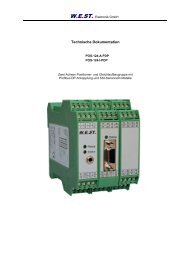
4.3 Circuit diagram<br />
12...30V<br />
0V<br />
Power supply<br />
Input<br />
+/- 10 V,<br />
+/- 8 V,<br />
0...10 V<br />
0... 8 V<br />
essential for<br />
4... 20 mA<br />
Enable<br />
7<br />
8<br />
W.E.ST. Elektronik GmbH<br />
12 8 V reference voltage<br />
11<br />
10<br />
9<br />
13<br />
14 / 15<br />
S1.3<br />
P1<br />
S1.4 S1.5 S1.6<br />
MIN A<br />
P2<br />
MCU<br />
MIN B<br />
P5<br />
PWM<br />
<strong>PAM</strong>-<strong>193</strong>-*<br />
Power stage<br />
Page 12 of 23 <strong>PAM</strong>-<strong>193</strong>-*-<strong>4021</strong> 02.08.2012<br />
P6<br />
RAMP<br />
MAX A<br />
P3 P4<br />
S1.1 S1.2<br />
MAX B<br />
Solenoid current range<br />
ia<br />
ib<br />
5<br />
3<br />
4<br />
1<br />
2<br />
READY output<br />
Solenoid A<br />
Solenoid B
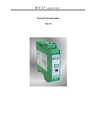
4.4 Typical cabling<br />
Joystick<br />
+/- 10 V (SPS / PLC) or<br />
+/- 8 V<br />
Potentiometer<br />
4... 20 mA (SPS / PLC)<br />
PIN 12 8V<br />
PIN 10 +In<br />
PIN 9 -In<br />
PIN 11 GND<br />
PIN 10 +In<br />
PIN 9 -In<br />
PIN 11 GND<br />
PIN 12 8V<br />
PIN 10 +In<br />
PIN 9 -In<br />
PIN 11 GND<br />
PIN 10 +In<br />
PIN 9 -In<br />
PIN 13<br />
SWITCH S1<br />
5 4 3<br />
ON OFF ON<br />
ON ON OFF<br />
SWITCH S1<br />
5 4 3<br />
OFF OFF OFF<br />
OFF OFF ON<br />
SWITCH S1<br />
5 4 3<br />
OFF ON OFF<br />
OFF ON ON<br />
SWITCH S1<br />
5 4 3<br />
ON OFF OFF<br />
ON ON ON<br />
W.E.ST. Elektronik GmbH<br />
+/- 4V ( 8 V)<br />
+/- 5V (10 V)<br />
+/- 10 V<br />
+/- 8 V<br />
0...5... 10 V<br />
0...4... 8 V<br />
4... 12... 20mA +/- 100%<br />
4... 20mA 0... 100%<br />
Caution: if using 4… 20 mA command signal PIN 9 has to be connected to PIN 13.<br />
For unipolar voltage signal PIN 9 has to be connected to PIN 11.<br />
PE<br />
Page 13 of 23 <strong>PAM</strong>-<strong>193</strong>-*-<strong>4021</strong> 02.08.2012<br />
1<br />
5<br />
9<br />
13<br />
2<br />
6<br />
10<br />
14<br />
Brücke/<br />
bridge<br />
4... 20 mA<br />
3<br />
7<br />
11<br />
15<br />
4<br />
8<br />
12<br />
16<br />
PE<br />
12 V / 24 V<br />
0V<br />
Spannungsversorgung /<br />
Power Supply<br />
Schirm/<br />
Screen<br />
Magnet B /<br />
Solenoid B<br />
Magnet A /<br />
Solenoid A<br />
Ready output<br />
Analoger Sollwert /<br />
Analogue command signal<br />
0V<br />
Enable<br />
SWITCH S1<br />
2 1<br />
OFF OFF<br />
ON ON<br />
1,2 A<br />
2,6 A
4.5 Technical data<br />
Power supply<br />
Current consumption<br />
External fuse<br />
W.E.ST. Elektronik GmbH<br />
[VDC]<br />
[mA]<br />
[A]<br />
12… 30 (incl. ripple)<br />
5 Adjustment elements<br />
5.1 Potentiometer<br />
Front:<br />
P1 = MINA<br />
P2 = MINB<br />
P3 = MAXA<br />
P4 = MAXB<br />
Inside:<br />
P5 = PWM / DITHER<br />
P6 = RAMP<br />
5.2 Internal DIL switches<br />
Command signal range<br />
W.E.ST. Elektronik GmbH<br />
S1.5=OFF S1.4=OFF S1.3=OFF ±10 V Input<br />
S1.5=OFF S1.4=OFF S1.3=ON ±8 V Input<br />
S1.5=OFF S1.4=ON S1.3=OFF 0… 5… 10 V Input<br />
S1.5=OFF S1.4=ON S1.3=ON 0… 4… 8 V Input<br />
S1.5=ON S1.4=OFF S1.3=OFF 4… 12… 20 mA for ± 100%<br />
S1.5=ON S1.4=OFF S1.3=ON ±4 V Input (Joystick)<br />
S1.5=ON S1.4=ON S1.3=OFF ±5 V Input (Joystick)<br />
S1.5=ON S1.4=ON S1.3=ON 4… 20 mA for 0… 100%<br />
Output current range:<br />
S1.1 = OFF, S1.2 = OFF (up to 1,2 A)<br />
S1.1 = ON, S1.2 = ON (up to 2,6 A)<br />
PWM / DITHER function:<br />
S1.6 = OFF – PWM frequency is adjustable in the range of 80... 340 Hz.<br />
S1.6 = ON – PWM frequency is 2000 Hz, dither frequency is 60 Hz, dither amplitude is<br />
adjustable (0… 20 %).<br />
Page 15 of 23 <strong>PAM</strong>-<strong>193</strong>-*-<strong>4021</strong> 02.08.2012
5.3 Start-up<br />
W.E.ST. Elektronik GmbH<br />
Because of the type these valves have relatively great tolerances in comparison to the electronics. The<br />
adjustment can vary from valve to valve.<br />
MAX: Maximum current adjustment (P3 and P4). The maximum output current can be set from<br />
about 40% to 100% of the rated current range..<br />
MIN: Zero- / deadband adjustment (P1 and P2). The MIN-adjustment should be carried out after<br />
the MAX-adjustment. The presetting is 0 (fully anti-clockwise). According to valve adjustments<br />
approx.15 % to 35 % of the rated current are necessary.<br />
Preset a small input signal of nearly 3 % to 5 %. Increase the MIN value (rotate clockwise)<br />
continuously until the drive moves. From there you reduce the value (anti-clockwise) until the<br />
drive came to standstill again.<br />
Caution: By changing of the MAX-adjustment also the MIN-adjustment changes.<br />
RAMP: The ramp time is preset on roughly 50 ms (P6, smallest value, fully anti-clockwise). It will be<br />
prolonged by turning clockwise up to approx. 15 s. All ramp times are identical.<br />
Caution: Long ramp times and simultaneously short cycle times (cycle time < ramp time)<br />
can result in a hardly understandable behaviour because all movements are carried out<br />
strongly delayed.<br />
PWM/<br />
DITHER: With the adjustment of PWM / DITHER the valve hysteresis can be reduced clearly.<br />
PWM frequency (pre-adjustedt): The PWM frequency (S1.6 = OFF) can be chosen within<br />
the range of 80… 340 Hz. For many valves PWM frequency<br />
adjustment is best way trying to reduce the hysteresis.<br />
DITHER Amplitude: The dither amplitude (S1.6 = ON) can be adjusted between<br />
0… 20 %. If this mode is activated the PWM frequency<br />
is about 2000 Hz and the DITHER frequency<br />
nearly 60 Hz.<br />
Caution: the best setting please take out of the valve data specification.<br />
Page 16 of 23 <strong>PAM</strong>-<strong>193</strong>-*-<strong>4021</strong> 02.08.2012
5.4 General behaviour:<br />
W.E.ST. Elektronik GmbH<br />
Power ON: After switching on the input signal (4… 20 mA) is checked and the system is gets activated.<br />
When ENABLE is active (ENABLE directly connected with the supply voltage) the current is<br />
activated by an internally defined ramp (smooth starting) in order to drive onto the demand<br />
value with the pre-set ramp time.<br />
If an error is detected the module changes over into error status.<br />
ENABLE: By this switching-input the internal signal processing and the power stage are enabled. While<br />
activating the input the valve current will be driven up the pre-set ramp. In case of deactivating<br />
the current is switched off immediately. PIN 5 monitors the state of readiness.<br />
Caution: This input is not suitable for stopping power stage in security relevant systems.<br />
LEDs: Green LED ON = ready for operation.<br />
Green LED flashes if command signal is lower than 2mA (4… 20mA adjustment) and in case<br />
of detected cable break to the solenoid. The output current is switched off immediately.<br />
Page 17 of 23 <strong>PAM</strong>-<strong>193</strong>-*-<strong>4021</strong> 02.08.2012
6 Appendix<br />
6.1 Failure monitoring<br />
W.E.ST. Elektronik GmbH<br />
Following possible error sources are monitored continuously:<br />
Source Fault Characteristic<br />
Command signal PIN 9/10<br />
4...20 mA<br />
Solenoid A PIN 3/4<br />
Solenoid B PIN 1/2<br />
6.2 Troubleshooting<br />
FAULT CAUSE / SOLUTION<br />
ENABLE is active, the<br />
module does not respond,<br />
and the READY<br />
LED is off.<br />
ENABLE is active, the<br />
READY LED is flashing.<br />
Out of range The power stage is deactivated.<br />
Broken wire The power stage is deactivated.<br />
Probably the power supply is disconnected or the ENABLE signal is not present.<br />
The flashing READY LED indicates that a fault is detected by the module. The fault<br />
could be:<br />
No signal at the input, if 4… 20 mA signal is chosen<br />
A broken cable or incorrect wiring to the solenoids.<br />
Page 18 of 23 <strong>PAM</strong>-<strong>193</strong>-*-<strong>4021</strong> 02.08.2012
6.3 Replacements / compatibility<br />
W.E.ST. Elektronik GmbH<br />
The <strong>PAM</strong>-191 and the <strong>PAM</strong>-192 are replaced by the <strong>PAM</strong>-<strong>193</strong>. If using the module as spare parts for older<br />
ones the wiring has to be adapted. It also has to be paid attention to the different configuration of the<br />
DIL-switches and potentiometers.<br />
6.3.1 <strong>PAM</strong>-191<br />
12..30V<br />
0V<br />
Power supply<br />
Changes (<strong>PAM</strong>-<strong>193</strong> / <strong>PAM</strong>-191)<br />
Wiring:<br />
PWM input<br />
Input<br />
0... 10V,<br />
0... 20 mA,<br />
4... 20 mA...<br />
Enable<br />
1. PIN 9 and PIN 10 are realized as differential input. For using unipolar voltage signals PIN 9 has<br />
to be connected with PIN 11.<br />
2. The input resistor for current signals can’t be switched on by DIL-switch anymore, but has to be<br />
activated by connecting PIN 9 and PIN 13.<br />
Adjustment:<br />
7<br />
8<br />
12<br />
11<br />
13<br />
10<br />
9<br />
14<br />
0 V<br />
0 V<br />
S2.1<br />
S2.3<br />
P1<br />
8 V<br />
10 V<br />
4... 20 mA<br />
S2.2<br />
MIN<br />
MCU<br />
reference voltages<br />
P3<br />
RAMP<br />
P4<br />
DITHER<br />
<strong>PAM</strong>-191<br />
Power stage<br />
3. Reference voltage on PIN 12 is 8 V and not changeable anymore. Further function is still possible<br />
by different signal ranges adjustable via DIL-switches.<br />
4. There are now only two output current ranges available: 1,2 A and 2,6 A. Default setting remains<br />
1 A. For significant lower currents the L-Version with half output current is available.<br />
5. The function, position and name of the potentiometers and DIL-switches partially have changed,<br />
(have a look at 5.1 und 5.2 in this documentation).<br />
Page 19 of 23 <strong>PAM</strong>-<strong>193</strong>-*-<strong>4021</strong> 02.08.2012<br />
MAX<br />
P2<br />
S1.1 S1.2<br />
1 A<br />
1,6 A<br />
3<br />
4
6.3.2 <strong>PAM</strong>-192<br />
12..30V<br />
Changes (<strong>PAM</strong>-192 / <strong>PAM</strong>-191)<br />
Wiring:<br />
0V<br />
Power supply<br />
Input<br />
+/- 10 V,<br />
+/- 5 V,<br />
4...20 mA<br />
W.E.ST. Elektronik GmbH<br />
1. The input resistor for current signals can’t be switched on by DIL-switch anymore, but has to be<br />
activated by connecting PIN 9 and PIN 13.<br />
2. CAUTION: Solenoid A and solenoid B have to be swapped.<br />
Adjustment:<br />
Enable<br />
7<br />
8<br />
12 8 V Reference voltage<br />
11<br />
13<br />
10<br />
9<br />
15<br />
U/I switch<br />
S1.6<br />
P1<br />
MIN A<br />
P2<br />
MCU<br />
MIN B<br />
P5<br />
Ramp up<br />
Power amplifiers<br />
3. There are now only two output current ranges available: 1,2 A and 2,6 A. Default setting remains<br />
1 A. For significant lower currents the L-Version with half output current is available.<br />
4. The function, position and name of the potentiometers and DIL-switches partially have changed,<br />
(have a look at 5.1 und 5.2 in this documentation).<br />
Page 20 of 23 <strong>PAM</strong>-<strong>193</strong>-*-<strong>4021</strong> 02.08.2012<br />
P6<br />
Ramp down<br />
MAX A<br />
P3 P4<br />
MAX B<br />
5<br />
2<br />
1 + 4<br />
3<br />
Ready<br />
Solenoid A<br />
Solenoid B
6.3.3 Special versions<br />
W.E.ST. Elektronik GmbH<br />
These special versions can be replaced by the <strong>PAM</strong>-<strong>193</strong>:<br />
<strong>PAM</strong>-191-*-S1 (PWM = 100Hz) = <strong>PAM</strong>-<strong>193</strong>-P<br />
<strong>PAM</strong>-191-*-S2 (PWM = 100Hz) = <strong>PAM</strong>-<strong>193</strong>-L<br />
<strong>PAM</strong>-192-*-S1 (PWM = 100Hz) = <strong>PAM</strong>-<strong>193</strong>-L<br />
<strong>PAM</strong>-192-*-S2 (PWM = 135Hz) = <strong>PAM</strong>-<strong>193</strong>-L<br />
Page 21 of 23 <strong>PAM</strong>-<strong>193</strong>-*-<strong>4021</strong> 02.08.2012
7 Notes<br />
W.E.ST. Elektronik GmbH<br />
Page 22 of 23 <strong>PAM</strong>-<strong>193</strong>-*-<strong>4021</strong> 02.08.2012