condair Esco - Walter Meier
condair Esco - Walter Meier
condair Esco - Walter Meier

You also want an ePaper? Increase the reach of your titles
YUMPU automatically turns print PDFs into web optimized ePapers that Google loves.
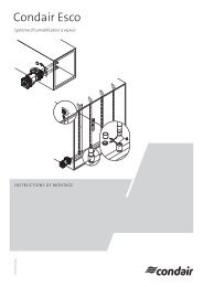
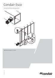
<strong>Esco</strong><br />
steam humidification system<br />
InstallatIon InstructIons<br />
1117775 En 1206 <strong>condair</strong><br />
L
Contents<br />
1 Introduction 4<br />
1.1 General 4<br />
1.2 Safety 4<br />
2 <strong>Esco</strong> DL40 5<br />
2.1 Overview <strong>Esco</strong> DL40 5<br />
2.2 Mounting the <strong>Esco</strong> DL40 7<br />
2.2.1 Mounting the <strong>Esco</strong> DL40 with one steam pipe 7<br />
2.2.2 Mounting the <strong>Esco</strong> DL40 with two/three steam pipes 10<br />
3 <strong>Esco</strong> DR73 17<br />
3.1 Overview <strong>Esco</strong> DR73 17<br />
3.2 Mounting the <strong>Esco</strong> DR73 A type 19<br />
3.3 Mounting the <strong>Esco</strong> DR73 B type 25<br />
4 <strong>Esco</strong> DR73 J 31<br />
4.1 Overview <strong>Esco</strong> DR73 J 31<br />
4.2 Mounting the <strong>Esco</strong> DR73 J (Jumbo) 32<br />
5 Mounting the steam supply line, the primary and secondary condensate and the manometer 41<br />
5.1 Connect the steam supply line (by client) 41<br />
5.2 Mounting the secondary condensate drain 42<br />
5.3 Mounting the primary condensate drain 43<br />
5.3.1 Thermostatic steam trap for <strong>Esco</strong> cast-iron and stainless steel versions 43<br />
5.3.2 Spheric float drain for <strong>Esco</strong> cast-iron version 44<br />
5.3.3 Bell-shaped float drain for <strong>Esco</strong> cast-iron version 44<br />
5.3.4 Spheric float drain and bell-shaped float drain for <strong>Esco</strong> stainless steel versions 45<br />
5.3.4.1 Spheric float drain for <strong>Esco</strong> stainless steel versions 45<br />
5.3.4.2 Bell-shaped float drain for <strong>Esco</strong> stainless steel versions 46<br />
5.4 Mounting the manometer 47<br />
3
4<br />
1 Introduction<br />
1.1 General<br />
1.2 Safety<br />
The present installation instructions are a supplement of the installation and operating instructions<br />
of the Condair <strong>Esco</strong> and describe the installation of the different steam distribution systems of the<br />
Condair <strong>Esco</strong> in a duct. The electrical connection of the valve actuators is not part of these installation<br />
instructions.<br />
Inappropriate installation of the steam distribution system may result in steam leakage during operation.<br />
Withdrawing steam may cause injury of person or damage of material assets.<br />
Therefore, please observe and comply with the following safety instructions and the information<br />
and safety instructions contained in the installation and operating instructions of the Condair <strong>Esco</strong>.<br />
• The steam distribution system Condair <strong>Esco</strong> must only be installed by persons familiar with this<br />
product and sufficiently qualified for the task.<br />
• All instructions in the present installation instructions must be followed and complied with.<br />
• Original Condair accessories and options from your supplier must be used exclusively for<br />
installation of the steam distribution system Condair <strong>Esco</strong>.<br />
• Without the written consent of the supplier, no attachments or modifications must be made to<br />
the steam distribution systems Condair <strong>Esco</strong>, accessories, and options.<br />
• All local safety regulations concerning the use of pressurised steam systems must be followed<br />
complied with.<br />
• It is assumed that all persons in charge with the installation of the steam distribution system are<br />
familiar and comply with the appropriate regulations on work safety and the prevention of accidents.<br />
• The weight of some components of the steam distribution system is more than 20 kg. Therefore,<br />
always transport these components with the help of another person or use an appropriate lifting<br />
device. Always secure the components during installation against falling down.<br />
• After the installation or during the initial start-up of the system all installations must be checked<br />
for tightness. Systems with leaky installations may not be taken in operation.
2 <strong>Esco</strong> DL40<br />
2.1 Overview <strong>Esco</strong> DL40<br />
DL40 - 1 pipe<br />
DL40 - 2 pipes<br />
DL40 - 3 pipes<br />
Primary condensate drain<br />
Thermostatic steam trap<br />
Spheric float drain<br />
Bell-shaped float drain<br />
Secondary condensate drain<br />
Thermostatic steam trap<br />
Manometer<br />
<strong>Esco</strong> 5 cast iron <strong>Esco</strong> 10 cast iron <strong>Esco</strong> 20 cast iron<br />
>20 kg<br />
5
6<br />
DL40 - 1 pipe<br />
DL40 - 2 pipes<br />
DL40 - 3 pipes<br />
Primary condensate drain<br />
Thermostatic steam trap<br />
Spheric float drain<br />
Bell-shaped float drain<br />
Secondary condensate drain<br />
Thermostatic steam trap<br />
Manometer<br />
<strong>Esco</strong> 10 stainless steel <strong>Esco</strong> 20 stainless steel
2.2 Mounting the <strong>Esco</strong> DL40<br />
2.2.1 Mounting the <strong>Esco</strong> DL40 with one steam pipe<br />
1. Fix drilling template supplied (self-adhesive), then drill holes.<br />
<strong>Esco</strong> 5 <strong>Esco</strong> 10 <strong>Esco</strong> 20<br />
d1<br />
d2<br />
ø9 mm<br />
ø13 mm **<br />
ø45 mm ø45 mm ø65 mm<br />
d3 ø13 mm<br />
** if mounting set for insulated ducts is used<br />
2. Mount valve unit.<br />
• Remove protective plug from the connector flange of the valve unit.<br />
• This step must be carried out only if mounting set for insulated ducts is used: Cut length of<br />
the supporting tubes to duct wall thickness “L”, then insert the tubes into the fixing holes.<br />
• Fix valve unit to the duct as shown below using the screws, washers and nuts. Before tightening,<br />
centrically align the bores of the duct and the valve unit.<br />
Screws washers and nuts for non insulated ducts<br />
(by client)<br />
<strong>Esco</strong> 5 <strong>Esco</strong> 10 <strong>Esco</strong> 20<br />
1 M8 x * (Wrench size 13 mm)<br />
2 ø24/8.4 x 2 mm<br />
3 M8 x 0.8d<br />
* length as required<br />
Mounting set for insulated ducts<br />
L<br />
<strong>Esco</strong> 5 <strong>Esco</strong> 10 <strong>Esco</strong> 20<br />
1<br />
M8 x 70 mm **/ M8 x 100 mm **<br />
Wrench size 13 mm<br />
2 ø24/8.4 x 2 mm<br />
3 ø12/8.5 x 45 mm **/ ø12/8.5 x 100 mm **<br />
4 M8 x 0.8d<br />
** as ordered<br />
L<br />
1<br />
2<br />
3<br />
1<br />
2<br />
3<br />
4<br />
1/2<br />
1/2<br />
d1<br />
d2<br />
d1<br />
d3<br />
Correct installation position <strong>Esco</strong> 5:<br />
Writing must be readable<br />
7
8<br />
3. Mounting the steam pipe.<br />
• Remove protective caps from the steam pipe.<br />
• From the inside of the duct push the steam pipe into the valve unit until it comes to a stop (the<br />
resistance of the O-ring inside the valve unit must be overcome). The steam pipe is installed<br />
correctly, if the secondary condensate drain pipe pokes X mm out of the duct (see illustration<br />
and table below).<br />
Note: To improve gliding ability moisten the end of the steam pipe and the O-ring inside the<br />
valve unit with water (do not use oil or grease!).<br />
Water<br />
4. Fix steam pipe.<br />
• Horizontally align steam pipe using a spirit level, then fix the end of the steam pipe to the duct<br />
wall or the duct ceiling (by client).<br />
• Screw M5x6 grub screws (allen key 2.5 mm) provided on both sides into the valve unit, until<br />
they touch the steam pipe.<br />
X<br />
<strong>Esco</strong> 5 <strong>Esco</strong> 10 <strong>Esco</strong> 20<br />
X 30 mm 24 mm 50 mm
5. Seal the bores inside the duct with silicone-free sealant.<br />
6. Connecting the steam supply line (see chapter 5.1).<br />
7. Mounting the secondary condensate drain (see chapter 5.2).<br />
8. Mounting the primary condensate drain (see chapter 5.3).<br />
9. Mounting the manometer (see chapter 5.4).<br />
9
10<br />
2.2.2 Mounting the <strong>Esco</strong> DL40 with two/three steam pipes<br />
1. Fix drilling template supplied (self-adhesive), then drill holes.<br />
Note: exclusively use the drilling template in the plastic bag attached to the collector pipe.<br />
<strong>Esco</strong> 10 <strong>Esco</strong> 20<br />
d1 ø9 mm<br />
ø13 mm **<br />
d2<br />
ø45 mm<br />
d3 ø13 mm<br />
** if mounting set for insulated ducts is used<br />
0002110210 RevStd:<br />
Doppelkollektor <strong>Esco</strong> 10 211/xxx<br />
Double coupling <strong>Esco</strong> 10 211/xxx<br />
Raccord double <strong>Esco</strong> 10 211/xxx<br />
0002110210 RevStd:<br />
Dreifachkollektor <strong>Esco</strong> 10 211/xxx<br />
Threefold coupling <strong>Esco</strong> 10 211/xxx<br />
Raccord triple <strong>Esco</strong> 10 211/xxx<br />
1120110<br />
122.9118<br />
1120117<br />
122.9133<br />
A<br />
B<br />
A<br />
A<br />
B<br />
B<br />
A<br />
d1<br />
d2<br />
d1<br />
d3<br />
d1<br />
d2<br />
d1<br />
d3<br />
d1<br />
d2<br />
d1<br />
d3<br />
d1<br />
d2<br />
d1<br />
d3<br />
d1<br />
d2<br />
d1<br />
d3
2. Mount collector pipe.<br />
• Remove protective plugs from the steam connectors of the collector pipe.<br />
• This step must be carried out only if mounting set for insulated ducts is used: Cut length of the<br />
supporting tubes to duct wall thickness “L”, then insert the tubes into the fixing holes.<br />
• Fix collector pipe to the duct as shown below using the screws, washers and nuts. Before<br />
tightening, centrically align the bores of the duct and the collector pipe.<br />
Screws washers and nuts for non insulated<br />
ducts (by client)<br />
<strong>Esco</strong> 10 <strong>Esco</strong> 20<br />
1 M8 x * (Wrench size 13 mm)<br />
2 ø24/8.4 x 2 mm<br />
3 M8 x 0.8d<br />
* length as required<br />
Mounting set for insulated ducts<br />
L<br />
<strong>Esco</strong> 10 <strong>Esco</strong> 20<br />
1<br />
M8 x 70 mm **/ M8 x 100 mm **<br />
Wrench size 13 mm<br />
2 ø24/8.4 x 2 mm<br />
3 ø12/8.5 x 45 mm **/ ø12/8.5 x 100 mm **<br />
4 M8 x 0.8d<br />
** as ordered<br />
L<br />
1<br />
2<br />
3<br />
1<br />
2<br />
3<br />
4<br />
11
12<br />
3. Mount steam pipes.<br />
• Remove protective caps from the steam pipes.<br />
• From the inside of the duct push the steam pipes into the connectors of the collector pipe until<br />
they come to a stop (the resistance of the O-ring inside the connectors of the collector pipe<br />
must be overcome). The steam pipes are installed correctly, if the secondary condensate drain<br />
pipe pokes 24 mm out of the duct.<br />
Note: To improve gliding ability moisten the end of the steam pipes and O-rings inside the<br />
connectors of the collector pipe with water (do not use oil or grease!).<br />
Water<br />
Water<br />
Water<br />
Water<br />
Water<br />
24 mm<br />
24 mm
4. Fix steam pipes.<br />
• Horizontally align steam pipes using a spirit level, then fix the ends of the steam pipes to the<br />
duct wall or the duct ceiling (by client).<br />
• Screw the M5x6 grub screws (allen key 2.5 mm) provided into the steam pipe connectors of<br />
the collector pipe (as shown below), until they touch the steam pipe.<br />
13
14<br />
5. Seal the bores inside the duct with silicone-free sealant.
6. Mount valve unit.<br />
• Remove protective cap/plug from the valve unit and the collector pipe.<br />
• Push valve unit onto the connector of the collector pipe until it comes to a stop (the resistance<br />
of the O-ring inside the valve unit must be overcome). Then, fix valve unit to the collector pipe<br />
as shown below using the screws, washers and nuts (wrench size 13 mm).<br />
Note: To improve the gliding ability moisten the steam connector of the collector pipe and the<br />
O-ring inside the valve unit with water (do not use oil or grease!).<br />
Water<br />
Water<br />
15
16<br />
7. Connecting the steam supply line (see chapter 5.1).<br />
8. Mounting the secondary condensate drain (see chapter 5.2).<br />
9. Mounting the primary condensate drain (see chapter 5.3).<br />
10. Mounting the manometer (see chapter 5.4).
3 <strong>Esco</strong> DR73<br />
3.1 Overview <strong>Esco</strong> DR73<br />
DR73 A type<br />
DR73 B type<br />
Primary condensate drain<br />
Thermostatic steam trap<br />
Spheric float drain<br />
Bell-shaped float drain<br />
Secondary condensate drain<br />
Thermostatic steam trap<br />
Manometer<br />
<strong>Esco</strong> 10 cast iron <strong>Esco</strong> 20 cast iron <strong>Esco</strong> 30 cast iron<br />
>20 kg >20 kg<br />
17
18<br />
DR73 A type<br />
DR73 B type<br />
Primary condensate drain<br />
Thermostatic steam trap<br />
Spheric float drain<br />
Bell-shaped float drain<br />
Secondary condensate drain<br />
Thermostatic steam trap<br />
Manometer<br />
<strong>Esco</strong> 10 stainless steel <strong>Esco</strong> 20 stainless steel
3.2 Mounting the <strong>Esco</strong> DR73 A type<br />
1. Fix drilling template supplied (self-adhesive), then drill holes.<br />
Z<br />
U<br />
d1<br />
d2<br />
d1<br />
d3<br />
d1<br />
<strong>Esco</strong> 10 <strong>Esco</strong> 20 <strong>Esco</strong> 30<br />
ø9 mm<br />
ø13 mm **<br />
ø13.5 mm<br />
ø17 mm **<br />
d2 ø45 mm ø65 mm ø95 mm<br />
d3 ø13 mm<br />
** if mounting set for insulated ducts is used<br />
<strong>Esco</strong> 10 <strong>Esco</strong> 20 <strong>Esco</strong> 30<br />
Z 160 mm 170 mm 170 mm<br />
U Distance between bottom edge of<br />
the duct up to the highest point of<br />
the duct floor<br />
19
20<br />
2. Mount valve unit.<br />
• Remove protective plug from the steam pipe connector of the valve unit.<br />
• This step must be carried out only if mounting set for insulated ducts is used: Cut length of<br />
the supporting tubes to duct wall thickness “L”, then insert the tubes into the fixing holes.<br />
• Fix valve unit to the duct as shown below using the screws, washers and nuts. Before tightening,<br />
centrically align the bores of the duct and the valve unit.<br />
Screws washers and nuts for non insulated ducts<br />
(by client)<br />
<strong>Esco</strong> 10 <strong>Esco</strong> 20 <strong>Esco</strong> 30<br />
1<br />
M8 x *<br />
Wrench size 13 mm<br />
M12 x *<br />
Wrench size 19 mm<br />
2 ø24/8.4 x 2 mm ø37/13 x 3 mm<br />
3 M8 x 0.8d M12 x 0.8d<br />
* length as required<br />
1<br />
2<br />
3 L<br />
1<br />
Mounting set for insulated ducts<br />
<strong>Esco</strong> 10 <strong>Esco</strong> 20 <strong>Esco</strong> 30<br />
M8 x 70 mm **<br />
M8 x 100 mm **<br />
Wrench size 13 mm<br />
M12 x 70 mm **<br />
M12 x 100 mm **<br />
Wrench size 19 mm<br />
2 ø24/8.4 x 2 mm ø37/13 x 3 mm<br />
3<br />
ø12/8.5 x 45 mm **<br />
ø12/8.5 x 100 mm **<br />
ø16/13 x 45 mm **<br />
ø16/13 x 70 mm **<br />
4 M8 x 0.8d M12 x 0.8d<br />
** as ordered<br />
L<br />
1<br />
2<br />
3<br />
4
3. Mount collector pipe.<br />
• Remove protective caps from the collector pipe.<br />
• From the inside of the duct push the collector pipe into the valve unit until it comes to a stop<br />
(the resistance of the O-ring inside the valve unit must be overcome). The collector pipe is<br />
installed correctly, if the secondary condensate drain pipe pokes X mm out of the duct (see<br />
illustration and table below).<br />
Note: To improve gliding ability moisten the end of the collector pipe and the O-ring inside the<br />
valve unit with water (do not use oil or grease!).<br />
X<br />
<strong>Esco</strong> 10 <strong>Esco</strong> 20 <strong>Esco</strong> 30<br />
Mass X 24 mm 50 mm 50 mm<br />
Water<br />
21
22<br />
4. Fix collector pipe.<br />
• Horizontally align collector pipe using a spirit level, then fix the end of the collector pipe with<br />
the bracket supplied to the duct floor or with the optional wall support to the duct wall.<br />
• Screw M5x6 grub screws (allen key 2.5 mm) provided on both sides into the valve unit, until<br />
they touch the steam pipe.
5. Seal the bores inside the duct with silicone-free sealant.<br />
23
24<br />
6. Mount vertical steam distribution pipes.<br />
• Remove protective plugs from the sockets of the collector pipe.<br />
• Push vertical steam distribution pipes into the sockets of the collector pipe until they come to a<br />
stop (the resistance of the O-rings inside the sockets must be overcome). Then, align nozzle<br />
apertures to the air flow according to drawing below.<br />
Note: To improve the gliding ability moisten the end of the vertical steam pipes and the O-rings<br />
inside the collector sockets with water (do not use oil or grease!).<br />
• Screw the M5x6 grub screws (allen key 2.5 mm) provided into the sockets (as shown below),<br />
until they touch the vertical steam distribution pipes.<br />
• Vertical steam distribution pipes with a length >1400 mm must be fixed to the duct ceiling using<br />
the brackets supplied. Before tightening the brackets vertically align steam pipes using a<br />
spirit level.<br />
L> 1400 mm<br />
air flow direction<br />
>200 mm >200 mm<br />
7. Connecting the steam supply line (see chapter 5.1).<br />
8. Mounting the secondary condensate drain (see chapter 5.2).<br />
9. Mounting the primary condensate drain (see chapter 5.3).<br />
10. Mounting the manometer (see chapter 5.4).<br />
3.3 Mounting the <strong>Esco</strong> DR73 B type<br />
1. Fabricate collector supporting sheet (by client).<br />
d2<br />
d1<br />
d3<br />
• Cut collector supporting sheet (L= as required, B= 20 mm more than flange width or flange<br />
outer diameter of the valve unit used)<br />
• Mark holes on the collector supporting sheet using the template supplied, then drill holes.<br />
• Holes “d4” must not be drilled until the collector supporting sheet is fixed to the duct.<br />
d4<br />
<strong>Esco</strong> 10 <strong>Esco</strong> 20 <strong>Esco</strong> 30<br />
d1 ø9 mm ø13.5 mm<br />
d2 ø45 mm ø65 mm ø95 mm<br />
d3 ø13 mm<br />
B<br />
L<br />
25
26<br />
2. Mark holes on the duct floor, then drill holes.<br />
• Measure dimensions “LX” , “C” , “da” and “BX” (thickness of the collector supporting sheet).<br />
• Mark holes according to the illustration below, then drill holes.<br />
T<br />
<strong>Esco</strong> 10 <strong>Esco</strong> 20 <strong>Esco</strong> 30<br />
T 69 mm ** 95 mm ** 95 mm **<br />
DX<br />
Distance between the first bore to<br />
the outer wall of the duct<br />
DX= LX-T-BX<br />
C Distance according measurement<br />
db<br />
Diameter of the bores<br />
db= da+2 mm<br />
** imperatively observe the dimensions indicated<br />
DX<br />
BX<br />
T<br />
BX<br />
DX C<br />
C<br />
C<br />
LX<br />
db<br />
da<br />
U2<br />
U2 max:
3. Fix collector pipe to the duct floor using self-tapping screws.<br />
Caution! Until the definite supports are installed (step 4) the collector pipe must be secured with<br />
auxiliary supports against falling down.<br />
4. Mount supports.<br />
• Remove protective plugs from the steam pipe connector and the condensate pipe connector.<br />
• Slide supporting sheet onto the collector pipe and fix it to the duct wall using two self-tapping<br />
screws (check dimension “T”).<br />
• Fabricate a support in order to support the angled end of the collector pipe (by client), then<br />
mount the support.<br />
Note: for collector pipes with more than 10 vertical steam distribution pipes an additional support<br />
must be mounted in the middle of the collector pipe.<br />
<strong>Esco</strong> 10 <strong>Esco</strong> 20 <strong>Esco</strong> 30<br />
T 69 mm ** 95 mm ** 95 mm **<br />
** imperatively observe the dimensions indicated<br />
T<br />
27
28<br />
5. Mount valve unit.<br />
• Remove protective plug from the valve unit.<br />
• Push valve unit onto the steam pipe until it comes to a stop (the resistance of the O-ring inside<br />
the valve unit must be overcome). Then, fix valve unit to the supporting sheet as shown below<br />
using two screws, washers and nuts each.<br />
Note: To improve the gliding ability moisten the steam connector of the collector pipe and the<br />
O-ring inside the valve unit with water (do not use oil or grease!).<br />
• Screw the M5x6 grub screws (allen key 2.5 mm) provided on both sides into the valve unit (as<br />
shown below), until they touch the steam pipe.<br />
<strong>Esco</strong> 10 <strong>Esco</strong> 20 <strong>Esco</strong> 30<br />
M8 x 35<br />
Wrench size 13 mm<br />
M12 x 35<br />
Wrench size 19 mm<br />
Water
6. Mount vertical steam distribution pipes.<br />
• Remove protective plugs from the sockets of the collector pipe.<br />
• Push vertical steam distribution pipes into the sockets of the collector pipe until they come to<br />
a stop (the resistance of the O-rings inside the sockets must be overcome). Then, align nozzle<br />
apertures to the air flow according to drawing below.<br />
Note: To improve the gliding ability moisten the end of the vertical steam pipes and the O-rings<br />
inside the collector sockets with water (do not use oil or grease!).<br />
• Screw the M5x6 grub screws (allen key 2.5 mm) provided into the sockets (as shown below),<br />
until they touch the vertical steam distribution pipes.<br />
• Vertical steam distribution pipes with a length >1400 mm must be fixed to the duct ceiling using<br />
the brackets supplied. Before tightening the brackets vertically align steam pipes using a<br />
spirit level.<br />
L> 1400 mm<br />
Air flow direction<br />
>200 mm >200 mm<br />
L<br />
Air flow direction<br />
30<br />
7. Connecting the steam supply line (see chapter 5.1).<br />
8. Mounting the secondary condensate drain (see chapter 5.2).<br />
9. Mounting the primary condensate drain (see chapter 5.3).<br />
10. Mounting the manometer (see chapter 5.4).
4 <strong>Esco</strong> DR73 J<br />
4.1 Overview <strong>Esco</strong> DR73 J<br />
DR73 JA Left<br />
DR73 JA Right<br />
DR73 J2A Left Right<br />
DR73 J2A Right Middle<br />
DR73 J2A Left Middle<br />
Primary condensate drain<br />
Spheric float drain<br />
Bell-shaped float drain<br />
Secondary condensate drain<br />
Thermostatic steam trap<br />
Manometer<br />
<strong>Esco</strong> 20 cast iron <strong>Esco</strong> 20 stainless steel <strong>Esco</strong> 30 cast iron<br />
>20 kg<br />
>20 kg<br />
31
32<br />
4.2 Mounting the <strong>Esco</strong> DR73 J (Jumbo)<br />
1. Fix drilling template supplied (self-adhesive), then drill holes (illustration below shows DR73 J2A<br />
Left Right).<br />
Note: Dimensions for the placement of the drilling templates see following hole pattern.<br />
Z<br />
U<br />
XX<br />
d1<br />
d2<br />
d1<br />
YY<br />
= =<br />
d3<br />
XX<br />
these holes must not be drilled!<br />
d1 ø9 mm<br />
ø13 mm **<br />
<strong>Esco</strong> 20 <strong>Esco</strong> 30<br />
ø13.5 mm<br />
ø17 mm **<br />
d2 ø65 mm ø95 mm<br />
d3 ø13 mm<br />
** if mounting set for insulated ducts is used<br />
d1<br />
d2<br />
d1
60 80<br />
øa<br />
ø95<br />
80<br />
Hole pattern DR73 JA Right (dimensions in mm)<br />
Internal dimension of duct<br />
Z<br />
140<br />
U<br />
Hole pattern DR73 J2A Link Right (dimensions in mm)<br />
ø13<br />
XX XX<br />
N<br />
YY/2<br />
YY<br />
YY/2 YY/2<br />
N<br />
Front view Top view<br />
YY<br />
YY/2<br />
XX<br />
Front view Top view<br />
ø95<br />
80<br />
140<br />
Z<br />
Kanalinnenmass<br />
U<br />
60 80<br />
Hole pattern DR73 JA Left (dimensions in mm)<br />
60 80<br />
øa<br />
ø95<br />
80<br />
ø13<br />
XX<br />
ø13<br />
ø95<br />
øa<br />
Front view Top view<br />
N<br />
YY<br />
YY/2 YY/2<br />
140<br />
Z<br />
Kanalinnenmass<br />
U<br />
XX<br />
XX<br />
XX<br />
XX<br />
YY<br />
YY<br />
YY<br />
35<br />
35<br />
35<br />
35<br />
35<br />
35<br />
33
34<br />
Hole pattern DR73 J2A Left Middle (dimensions in mm)<br />
60 80<br />
øa<br />
ø95<br />
80<br />
ø13<br />
XX<br />
Front view Top view<br />
N<br />
ø95<br />
YY<br />
YY/2 YY/2<br />
140<br />
Z<br />
Kanalinnenmass<br />
Hole pattern DR73 J2A Right Middle (dimensions in mm)<br />
Internal dimension of duct<br />
Z<br />
140<br />
U<br />
<strong>Esco</strong> 20<br />
<strong>Esco</strong> 30<br />
YY/2<br />
N<br />
ø95<br />
N<br />
(Collector)<br />
U<br />
XX<br />
Front view Top view<br />
YY<br />
YY/2<br />
XX<br />
ø13<br />
ø95<br />
80<br />
øa<br />
60 80<br />
XX<br />
YY<br />
YY<br />
XX ** YY ** YY/2 ** Z a U<br />
120 x 120 mm 220 mm 190 mm 95 mm 170 mm ø9 mm<br />
(ø13 mm ***)<br />
100 x 100 mm 250,5 mm 170 mm 85 mm 170 mm ø13.5 mm<br />
(ø17 mm ***)<br />
120 x 120 mm 260,5 mm 190 mm 95 mm 170 mm<br />
** customised versions with deviating dimensions XX and YY possible<br />
*** if mounting set for insulated ducts is used<br />
35<br />
35<br />
35<br />
35<br />
Distance between<br />
bottom edge of the<br />
duct to the highest<br />
point of the duct<br />
floor
2. Mount valve unit.<br />
• Remove protective plug from the connector flange(s) of the valve unit(s).<br />
• This step must be carried out only if mounting set for insulated ducts is used: Cut length of<br />
the supporting tubes to duct wall thickness “L”, then insert the tubes into the fixing holes.<br />
• Fix valve unit(s) to the duct as shown below using the screws, washers and nuts. Before<br />
tightening, centrically align the bores of the duct and the valve unit.<br />
Screws washers and nuts for non insulated ducts<br />
(by client)<br />
<strong>Esco</strong> 20 <strong>Esco</strong> 30<br />
1<br />
M8 x *<br />
Wrench size 13 mm<br />
M12 x *<br />
Wrench size 19 mm<br />
2 ø24/8.4 x 2 mm ø37/13 x 3 mm<br />
3 M8 x 0.8d M12 x 0.8d<br />
* length as required<br />
1<br />
2<br />
3 L<br />
1<br />
Mounting set for insulated ducts<br />
<strong>Esco</strong> 20 <strong>Esco</strong> 30<br />
M8 x 70 mm **<br />
M8 x 100 mm **<br />
Wrench size 13 mm<br />
M12 x 70 mm **<br />
M12 x 100 mm **<br />
Wrench size 19 mm<br />
2 ø24/8.4 x 2 mm ø37/13 x 3 mm<br />
3<br />
ø12/8.5 x 45 mm **<br />
ø12/8.5 x 100 mm **<br />
ø16/13 x 45 mm **<br />
ø16/13 x 70 mm **<br />
4 M8 x 0.8d M12 x 0.8d<br />
** as ordered<br />
L<br />
1<br />
2<br />
3<br />
4<br />
35
36<br />
3. Mount collector pipe (illustration below shows DR73 J2A Left Right).<br />
• Remove protective caps from the collector pipe.<br />
• From the inside of the duct push the connector(s) of the collector pipe into the valve unit(s)<br />
until it/they come(s) to a stop (the resistance of the O-ring inside the valve unit(s) must be<br />
overcome). The collector pipe is installed correctly, if the secondary condensate drain pipe<br />
pokes 50 mm out of the duct (see illustration below).<br />
Note: To improve gliding ability moisten the end/ends of the collector pipe connector(s) and<br />
the O-ring(s) inside the valve unit(s) with water (do not use oil or grease!).<br />
50 mm<br />
Water<br />
Water
4. Fix collector pipe (illustration below shows DR73 J2A Left Right).<br />
• Horizontally align collector pipe using a spirit level, then fix the end of the collector pipe with the<br />
brackets supplied to the duct floor or with the optional wall support to the duct wall.<br />
• Screw the M5x6 grub screws (allen key 2.5 mm) provided on into the flange pipe of the valve<br />
unit, until they touch the steam pipe.<br />
37
38<br />
5. Seal the bores inside the duct with silicone-free sealant.
200 mm<br />
6. Mount vertical steam distribution pipes.<br />
• Remove protective plugs from the sockets of the collector pipe.<br />
• Push vertical steam distribution pipes into the sockets of the collector pipe until they come to a<br />
stop (the resistance of the O-rings inside the sockets must be overcome). Then, align nozzle<br />
apertures to the air flow according to drawing below.<br />
Note: To improve the gliding ability moisten the end of the vertical steam pipes and the O-rings<br />
inside the collector sockets with water (do not use oil or grease!).<br />
• Screw the M5x6 grub screws (allen key 2.5 mm) provided into the sockets (as shown below),<br />
until they touch the vertical steam distribution pipes.<br />
• Vertical steam distribution pipes with a length >1400 mm must be fixed to the duct ceiling using<br />
the brackets supplied. Before tightening the brackets vertically align steam pipes using a<br />
spirit level.<br />
L> 1400 mm<br />
L<br />
200 m<br />
Air flow direction<br />
40<br />
7. Connecting the steam supply line (see chapter 5.1).<br />
8. Mounting the secondary condensate drain (see chapter 5.2).<br />
9. Mounting the primary condensate drain (see chapter 5.3).<br />
10. Mounting the manometer (see chapter 5.4).
5 Mounting the steam supply line, the primary and<br />
secondary condensate and the manometer<br />
5.1 Connect the steam supply line (by client)<br />
Note: the steam supply line must be made according to the instructions in chapter 5 of the installation<br />
and operating instructions of the Condair <strong>Esco</strong>. Steam supply lines with a length of more than<br />
4 m between the branch connection of the main steam line and the connecting flange of the valve<br />
unit must mandatory be drained.<br />
G 1/2"<br />
<strong>Esco</strong> 5<br />
wrap teflon tape around the thread or apply<br />
silicone-free sealant<br />
(heat-resistant up to 155 °C)<br />
41
42<br />
5.2 Mounting the secondary condensate drain<br />
• Wrap teflon tape around the thread of the angled screw coupling or apply silicone-free sealant<br />
(heat-resistant up to 155 °C). Then, screw angled screw coupling into the secondary condensate<br />
drain (arrow on the thermostatic steam trap must point in drain direction).<br />
• Slide angled screw coupling onto the condensate pipe until it comes to a stop. Tighten union nut<br />
so far, that the angled screw coupling can not be turned by hand anymore.<br />
• The outlet of the secondary condensate drain must be connected to the drain line of the building<br />
via an open funnel (pressure-free draining) with siphon (by client).<br />
Thermostatic steam trap stainless steel<br />
Thermostatic steam trap brass<br />
Wrench size 22 mm<br />
wrap teflon tape around the thread or<br />
apply silicone-free sealant<br />
(heat-resistant up to 155 °C)<br />
G 1/2"<br />
G 1/2"<br />
Wrench size 32 mm<br />
Wrench size 19 mm<br />
wrap teflon tape around the thread or<br />
apply silicone-free sealant<br />
(heat-resistant up to 155 °C)<br />
admissible mounting position<br />
not admissible mounting position<br />
admissible mounting position<br />
not admissible mounting position<br />
5.2.1
5.3 Mounting the primary condensate drain<br />
Important notes<br />
– The primary condensate must be discharged separately from the secondary condensate.<br />
– The primary condensate can either be discharged pressure-free or with a maximum back-pressure<br />
of 1/2 of the primary steam pressure. The discharge/feedback of the primary condensate is<br />
customers responsibility.<br />
5.3.1 Thermostatic steam trap for <strong>Esco</strong> cast-iron and stainless steel versions<br />
• Wrap teflon tape around the threads of the threaded pipe or apply silicone-free sealant (heatresistant<br />
up to 155 °C). Then, screw threaded pipe into the primary condensate drain (arrow on<br />
the condensate drain must point in drain direction).<br />
• Remove protective plug from the condensate connector of the valve unit, then screw threaded<br />
pipe from the bottom into the valve unit.<br />
Flow direction<br />
G 1/2"<br />
wrap teflon tape around the thread or<br />
apply silicone-free sealant<br />
(heat-resistant up to 155 °C)<br />
Wrench size 32 mm<br />
admissible mounting position<br />
not admissible mounting position<br />
43
44<br />
5.3.2 Spheric float drain for <strong>Esco</strong> cast-iron version<br />
• Wrap teflon tape around the thread of the fitting or apply silicone-free sealant (heat-resistant up to<br />
155 °C). Then, screw fitting into the spheric float drain (arrow on the spheric float drain must<br />
be on top and point in drain direction).<br />
• Remove protective plug from the condensate connector of the valve unit, then fix spheric float<br />
drain to the valve unit using the banjo bolt and the copper rings.<br />
Wrench size 27 mm<br />
wrap teflon tape around the thread or<br />
apply silicone-free sealant<br />
(heat-resistant up to 155 °C)<br />
Wrench size 24 mm<br />
Wrench size 22 mm<br />
Flow direction<br />
G 1/2"<br />
5.3.3 Bell-shaped float drain for <strong>Esco</strong> cast-iron version<br />
G 1/2"<br />
Arrow on the type plate<br />
must point downwards<br />
• Wrap teflon tape around the thread of the fitting or apply silicone-free sealant (heat-resistant up<br />
to 155 °C). Then, screw fitting into the bell-shaped float (arrow on the bell-shaped float must be<br />
on top and point in drain direction).<br />
• Remove protective plug from the condensate connector of the valve unit, then fix bell-shaped<br />
float to the valve unit using the banjo bolt and the copper rings.<br />
Wrench size 27 mm<br />
Wrench size 24 mm<br />
Wrench size 22 mm<br />
wrap teflon tape around the thread or apply siliconefree<br />
sealant (heat-resistant up to 155 °C)<br />
Flow direction
5.3.4 Spheric float drain and bell-shaped float drain for <strong>Esco</strong> stainless<br />
steel versions<br />
Attention danger of mistake: the stainless steel spheric float drain can easily be mistaken with the<br />
stainless steel bell-shaped float drain. A mistake of the two floats leads to a malfunctioning during<br />
operation, since the two floats have different installation positions.<br />
Spheric float drain made of stainless steel Bell-shaped float drain made of stainless steel<br />
correct installation position<br />
Characteristics of the spheric float drain:<br />
– Designation “TOP” (on top)<br />
– plug screw (on the bottom)<br />
wrong installation position<br />
5.3.4.1 Spheric float drain for <strong>Esco</strong> stainless steel versions<br />
• Wrap teflon tape around the thread of the straight fitting or apply silicone-free sealant (heatresistant<br />
up to 155 °C). Then, remove protective plug from the condensate connector of the valve<br />
unit screw fitting into the valve unit.<br />
• Wrap teflon tape around the thread of the angled screw coupling or apply silicone-free sealant<br />
(heat-resistant up to 155 °C). Then, screw angled screw coupling into the spheric float drain as<br />
shown below (the union nut must point to the marking “TOP” and the arrow on the spheric<br />
float drain must point in drain direction).<br />
• Slide angled screw coupling with the spheric float drain onto the straight fitting until it comes to a<br />
stop. Tighten union nut so far, that the spheric float drain can not be turned by hand anymore.<br />
flow direction<br />
G 1/2"<br />
Wrench size 22 mm<br />
Wrench size 24 mm<br />
tighten screws after<br />
alignment!<br />
wrap teflon tape around the thread or apply silicone-free sealant<br />
(heat-resistant up to 155 °C)<br />
45
46<br />
5.3.4.2 Bell-shaped float drain for <strong>Esco</strong> stainless steel versions<br />
• Wrap teflon tape around the thread of the straight fitting or apply silicone-free sealant (heatresistant<br />
up to 155 °C). Then, remove protective plug from the condensate connector of the valve<br />
unit screw fitting into the valve unit.<br />
• Wrap teflon tape around the thread of the angled screw coupling or apply silicone-free sealant<br />
(heat-resistant up to 155 °C). Then, screw angled screw coupling into the bell-shaped float drain<br />
as shown below (the union nut must point to the top and the arrow on the bell-shaped float<br />
drain must point in drain direction).<br />
• Slide angled screw coupling with the bell-shaped float drain onto the straight fitting until it comes<br />
to a stop. Tighten union nut so far, that the bell-shaped float drain can not be turned by hand<br />
anymore.<br />
Wrench size 22 mm<br />
Wrench size 24 mm<br />
wrap teflon tape around the thread or apply silicone-free<br />
sealant (heat-resistant up to 155 °C)<br />
Flow direction<br />
G 1/2"
5.4 Mounting the manometer<br />
Wrap teflon tape around the thread<br />
or apply silicone-free sealant<br />
(heat-resistant up to 155 °C)<br />
47
Notes
Notes
Notes
© <strong>condair</strong> ltd., Printed in switzerland<br />
technical modifications reserved
consultInG, salEs and sErvIcE:<br />
reg.no. 40002-2<br />
Manufacturer:<br />
<strong>condair</strong> ltd.<br />
Member of the <strong>Walter</strong> <strong>Meier</strong> Group<br />
talstrasse 35-37, 8808 Pfäffikon, switzerland<br />
Ph. +41 55 416 61 11, Fax +41 55 416 62 62<br />
info@<strong>condair</strong>.com, www.<strong>condair</strong>.com