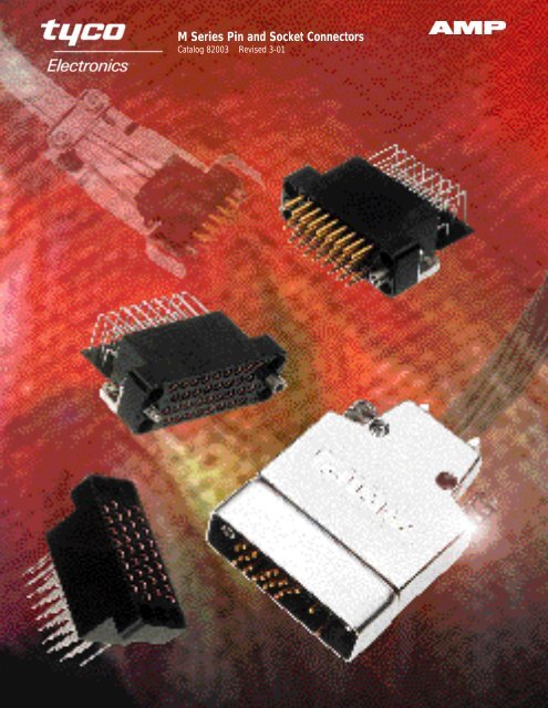
M Series Pin and Socket Connectors
M Series Pin and Socket Connectors
M Series Pin and Socket Connectors

You also want an ePaper? Increase the reach of your titles
YUMPU automatically turns print PDFs into web optimized ePapers that Google loves.
M <strong>Series</strong> <strong>Pin</strong> <strong>and</strong> <strong>Socket</strong> <strong>Connectors</strong><br />
Catalog 82003 Revised 3-01
2<br />
Product Facts<br />
■ Most connectors intermateable<br />
with connectors made to<br />
MIL-C-28748 requirements<br />
■ Wide range of connector styles<br />
<strong>and</strong> sizes: st<strong>and</strong>ard c o n n e c t o r s<br />
(unloaded), posted c o n n e c t o r s<br />
( p r e l o a d e d )<strong>and</strong> special application<br />
connectors (unloaded)<br />
■ Complete line of accessory<br />
hardware for fastening, protecting,<br />
guiding, shielding,<br />
strain relief <strong>and</strong> keying<br />
■ A variety of contacts: signal,<br />
power, coaxial <strong>and</strong> posted<br />
versions—many are interchangeable<br />
<strong>and</strong> can be<br />
intermixed in the same<br />
connector housing<br />
■ Full complement of application<br />
tooling for wire crimp <strong>and</strong><br />
posted terminations—h<strong>and</strong><br />
tools, semiautomatic tooling<br />
<strong>and</strong> fully automatic machines<br />
provide highly reliable, low<br />
cost terminations to meet<br />
production requirements<br />
Need More Information?<br />
Call the Technical<br />
Support Center:<br />
1-800-522-6752.<br />
The Center is staffed with<br />
specialists well versed in all<br />
AMP products <strong>and</strong> application<br />
tooling. The Center can<br />
provide you with:<br />
■ Technical Support<br />
■ Catalogs<br />
■ Technical Documents<br />
■ Product Samples<br />
■ AMP FAX Service—<br />
Product Information<br />
Faxed Immediately<br />
■ Authorized Distributor<br />
Locations<br />
Specifications subject to change.<br />
Consult Tyco Electronics Corporation<br />
for latest design specifications.<br />
©1968, 1970, 1972, 1974, 1978, 19 85, 19 9 0 ,<br />
19 9 6 <strong>and</strong> 2001 by Tyco Electronics<br />
Corporation. All Rights Reserved.<br />
AMP, AMP FAX, AMPOMATOR,<br />
AMP-O-LECTRIC, AMP-O-MATIC,<br />
AMP-TAPETRONIC, CERTI-CRIMP,<br />
COAXICON, LGH, POWERBAND,<br />
PRO-CRIMPER, RAYCHEM,<br />
TERMI-POINT <strong>and</strong> TYCOare trademarks.<br />
Other products, logos, <strong>and</strong> company<br />
names mentioned herein may be<br />
trademarks of their respective owners.<br />
Dimensions are shown for reference<br />
purposes only.<br />
M <strong>Series</strong><br />
<strong>Pin</strong> <strong>and</strong> <strong>Socket</strong> <strong>Connectors</strong><br />
M <strong>Series</strong> <strong>Connectors</strong><br />
Dimensions are in inches <strong>and</strong> millimeters<br />
unless otherwise specified.<br />
Values in brackets are metric equivalents.<br />
St<strong>and</strong>ard Housings<br />
Posted <strong>Connectors</strong><br />
Special Application <strong>Connectors</strong><br />
Specifications subject to change. Technical Support Center<br />
1-800-522-6752<br />
www.tycoelectronics.com<br />
Catalog 82003<br />
Revised 3-01
Dimensions are shown for reference<br />
purposes only.<br />
M <strong>Series</strong><br />
<strong>Pin</strong> <strong>and</strong> <strong>Socket</strong> <strong>Connectors</strong><br />
Table of Contents<br />
Product Facts . . . . . . . . . . . . . . . . . . . . . . . . . . . . . . . . . . . . . . 2<br />
Introduction . . . . . . . . . . . . . . . . . . . . . . . . . . . . . . . . . . . . . . 4, 5<br />
Material Specifications . . . . . . . . . . . . . . . . . . . . . . . . . . . . . . . . . . 6<br />
Current Carrying Capabilities . . . . . . . . . . . . . . . . . . . . . . . . . . . . . . 7, 8<br />
How to Use this Catalog . . . . . . . . . . . . . . . . . . . . . . . . . . . . . . . . . . 9<br />
Connector/Hardware Selection Guide (for Typical Applications)<br />
Cable-to-Cable . . . . . . . . . . . . . . . . . . . . . . . . . . . . . . . . . . . . . . . . . . . . . . . . . . . . . . .10-17<br />
Cable-to-Panel . . . . . . . . . . . . . . . . . . . . . . . . . . . . . . . . . . . . . . . . . . . . . . . . . . . . . . . .18-25<br />
Contacts (Description of Types) . . . . . . . . . . . . . . . . . . . . . . . . . . . 26-29<br />
Signal Contacts<br />
Type II, Crimp, Snap-In . . . . . . . . . . . . . . . . . . . . . . . . . . . . . . . . 30<br />
Type III+, Crimp, Snap-In; Posted; Solder Versions . . . . . . . . . . . . . . . . . 31-35<br />
Power Contacts<br />
Type I, Crimp, Snap-In . . . . . . . . . . . . . . . . . . . . . . . . . . . . . . . . . 36<br />
High Current Type II <strong>and</strong> Type III+ (Screw Machine, Crimp, Snap-In) . . . . . . . . . . 37<br />
Type XII, Crimp, Snap-In . . . . . . . . . . . . . . . . . . . . . . . . . . . . . . . . 38<br />
High Current Type XII (Screw Machine, Crimp, Snap-In) . . . . . . . . . . . . . . . . 39<br />
Coaxial Contacts<br />
Subminiature, Crimp, Snap-In, Size 16 . . . . . . . . . . . . . . . . . . . . . . . . . . . . . . . . . . . .40, 41<br />
Miniature, Crimp, Snap-In, Size 12 . . . . . . . . . . . . . . . . . . . . . . . . . 42, 43<br />
St<strong>and</strong>ard Housings—Introduction . . . . . . . . . . . . . . . . . . . . . . . . . . . . . 44<br />
6, 14, <strong>and</strong> 20-Positions . . . . . . . . . . . . . . . . . . . . . . . . . . . . . . . . 45<br />
26, 34 <strong>and</strong> 36-Positions . . . . . . . . . . . . . . . . . . . . . . . . . . . . . . 46, 47<br />
41 <strong>and</strong> 50-Positions . . . . . . . . . . . . . . . . . . . . . . . . . . . . . . . . 47, 48<br />
75 <strong>and</strong> 104-Positions . . . . . . . . . . . . . . . . . . . . . . . . . . . . . . . . . 49<br />
104 CF Positions (with Center Fastener) . . . . . . . . . . . . . . . . . . . . . . . . 50<br />
160 CF Positions (with Center Fastener) . . . . . . . . . . . . . . . . . . . . . . . . 51<br />
Posted <strong>Connectors</strong>—Introduction . . . . . . . . . . . . . . . . . . . . . . . . . . . . . 52<br />
6, 14, 20 <strong>and</strong> 26-Positions . . . . . . . . . . . . . . . . . . . . . . . . . . . . . 53, 54<br />
34 <strong>and</strong> 50 Positions . . . . . . . . . . . . . . . . . . . . . . . . . . . . . . . . 55, 56<br />
75 <strong>and</strong> 104-Positions . . . . . . . . . . . . . . . . . . . . . . . . . . . . . . . . . 57<br />
104 <strong>and</strong> 160 CF Positions (with Center Fastener) . . . . . . . . . . . . . . . . . . 58, 59<br />
15, 36 <strong>and</strong> 50 Positions (.200 [5.08] Grid) . . . . . . . . . . . . . . . . . . . . . 59, 60<br />
Special Application <strong>Connectors</strong>—Introduction . . . . . . . . . . . . . . . . . . . . . . . 61<br />
V.35 Special Application <strong>Connectors</strong>—Introduction . . . . . . . . . . . . . . . . 62, 63<br />
V.35 Printed Circuit Board <strong>Connectors</strong> . . . . . . . . . . . . . . . . . . . . . . . 64-67<br />
V.35 Cable <strong>Connectors</strong> . . . . . . . . . . . . . . . . . . . . . . . . . . . . . . . 68-71<br />
12-Positions, High Current Connector (UL Voltage Rating: 1800 V) . . . . . . . . . . . 72<br />
29 CF Position Connector with Mixed Contacts (with Center Fastener) . . . . . . . . . 73<br />
42-Positions, Connector with Mixed Contacts . . . . . . . . . . . . . . . . . . . . . 74<br />
20-Positions, High Voltage Connector (UL Voltage Rating: 1800 V) . . . . . . . . . . . 75<br />
28-Positions, High Voltage Connector (UL Voltage Rating: 1800 V) . . . . . . . . . . . 76<br />
14 <strong>and</strong> 34-Positions, Grounding Blocks <strong>and</strong> Fastening Hardware . . . . . . . . . . . . 77<br />
Hardware<br />
Fastening Hardware . . . . . . . . . . . . . . . . . . . . . . . . . . . . . . . . 78-80<br />
Guiding Hardware . . . . . . . . . . . . . . . . . . . . . . . . . . . . . . . . . . . 81<br />
Protective Hardware . . . . . . . . . . . . . . . . . . . . . . . . . . . . . . . . 82-87<br />
Strain Relief Hardware . . . . . . . . . . . . . . . . . . . . . . . . . . . . . . . . . 88<br />
Keying Hardware . . . . . . . . . . . . . . . . . . . . . . . . . . . . . . . . . . . 89<br />
Application Tooling . . . . . . . . . . . . . . . . . . . . . . . . . . . . . . . . . 90, 91<br />
Technical Documents . . . . . . . . . . . . . . . . . . . . . . . . . . . . . . . . 92, 93<br />
Part Number Index . . . . . . . . . . . . . . . . . . . . . . . . . . . . . . . . . 94, 95<br />
Dimensions are in inches <strong>and</strong> millimeters<br />
unless otherwise specified.<br />
Values in brackets are metric equivalents.<br />
Specifications subject to change. Technical Support Center<br />
1-800-522-6752<br />
www.tycoelectronics.com<br />
Catalog 82003<br />
Revised 3-01<br />
3
4<br />
Dimensions are shown for reference<br />
purposes only.<br />
M <strong>Series</strong><br />
<strong>Pin</strong> <strong>and</strong> <strong>Socket</strong> <strong>Connectors</strong><br />
Introduction<br />
AMP M <strong>Series</strong> connectors are<br />
one of the most versatile <strong>and</strong><br />
complete pin <strong>and</strong> socket connector<br />
lines available today.<br />
From the basic molded<br />
plastic housing, a connector<br />
can be built up with a<br />
wide choice of contacts <strong>and</strong><br />
hardware to serve in applications<br />
ranging from<br />
sophisticated computers,<br />
medical instrumentation<br />
<strong>and</strong> military ground support<br />
equipment to rugged truck<br />
transmissions.<br />
How this M <strong>Series</strong><br />
catalog is divided<br />
The M <strong>Series</strong> catalog is<br />
divided into six categories:<br />
■ Application section<br />
■ Contacts/Tooling<br />
■ St<strong>and</strong>ard Connector<br />
Housings<br />
■ Posted Connector<br />
Housings<br />
■ Special Application<br />
Connector Housings<br />
■ Hardware<br />
Following is a brief summary<br />
of each of the six categories.<br />
Knowing what you need<br />
to meet your application<br />
is made easy<br />
Eight applications have<br />
been illustrated with selection<br />
charts from pages 10<br />
through 25. These charts<br />
will assist you to select<br />
the appropriate connector<br />
housing as well as the<br />
necessary hardware. Each<br />
base part number is listed<br />
in the numerical index on<br />
pages 94, 95 in order to<br />
find complete information<br />
about a particular part.<br />
Contacts of various types<br />
provide different functions in<br />
M <strong>Series</strong> connector housings<br />
Included are contacts for<br />
signal <strong>and</strong> power applications,<br />
for coaxial cable<br />
<strong>and</strong> posted versions for<br />
backpanel wiring. A full<br />
complement of application<br />
tooling is available to meet<br />
any production requirement<br />
for terminating the crimptype<br />
contacts <strong>and</strong> wiring<br />
Dimensions are in inches <strong>and</strong> millimeters<br />
unless otherwise specified.<br />
Values in brackets are metric equivalents.<br />
posted contacts. A description<br />
of each contact type is<br />
presented on pages 26<br />
through 29. Application<br />
tooling for these contacts<br />
is described on pages<br />
90 <strong>and</strong> 91.<br />
St<strong>and</strong>ard connectors<br />
St<strong>and</strong>ard connectors are<br />
comprised of unloaded<br />
housings that accept a<br />
variety of crimp, solder<br />
<strong>and</strong> posted contacts. All<br />
st<strong>and</strong>ard connector housings<br />
will accept pins <strong>and</strong>/or<br />
sockets, permitting various<br />
combinations of contact<br />
loading. St<strong>and</strong>ard connectors<br />
are described on pages<br />
44 through 51.<br />
Posted connectors<br />
Posted connectors are<br />
preloaded with post-type<br />
contacts that accept<br />
TERMI-POINT Clip or<br />
wrap-type terminations.<br />
All posted connectors are<br />
described on pages 52<br />
through 60.<br />
Special Application connectors<br />
<strong>Connectors</strong> for special<br />
application are available in<br />
the following configurations:<br />
■ V.35<br />
■ High Current<br />
■ Mixed Contact<br />
<strong>Connectors</strong><br />
■ High Voltage<br />
■ RFI/EMI Shielded<br />
■ Grounding Blocks<br />
Special Application<br />
<strong>Connectors</strong> are described<br />
on pages 61 through 77.<br />
The right hardware for the<br />
entire M <strong>Series</strong> connector line<br />
Hardware is available to<br />
provide fastening, protection,<br />
shielding, guiding,<br />
strain relief <strong>and</strong> keying<br />
capabilities for the entire<br />
M <strong>Series</strong> connector line.<br />
Application charts for properly<br />
selecting hardware<br />
are presented on pages<br />
10 through 25. Detailed<br />
information on hardware<br />
is located on pages 78<br />
through 89.<br />
Specifications subject to change. Technical Support Center<br />
1-800-522-6752<br />
www.tycoelectronics.com<br />
Catalog 82003<br />
Revised 3-01
Dimensions are shown for reference<br />
purposes only.<br />
M <strong>Series</strong><br />
<strong>Pin</strong> <strong>and</strong> <strong>Socket</strong> <strong>Connectors</strong><br />
Introduction (Continued)<br />
What makes the M <strong>Series</strong><br />
connector line so versatile<br />
<strong>and</strong> special for a wide variety<br />
of applications?<br />
■ Compatibility–Most<br />
connectors intermateable<br />
with connectors made to<br />
M I L - C - 2 8 7 4 8 requirements.<br />
■ Wide range–Choice of<br />
connector styles <strong>and</strong><br />
sizes: st<strong>and</strong>ard connectors<br />
(unloaded), posted<br />
connectors (preloaded)<br />
<strong>and</strong> special application<br />
connectors.<br />
■ Complete line–Full line of<br />
accessory hardware for<br />
fastening, protecting, guiding,<br />
strain relief <strong>and</strong> keying.<br />
■ Variety of contacts–S i g n a l ,<br />
power, coaxial, <strong>and</strong><br />
posted versions—many<br />
are interchangeable <strong>and</strong><br />
can be intermixed in the<br />
same connector housing.<br />
■ Full complement of application<br />
tooling–For wire crimp<br />
<strong>and</strong> posted terminations<br />
h<strong>and</strong> tools, semiautomatic<br />
tooling <strong>and</strong> fully automatic<br />
machines provide highly<br />
reliable, low cost terminations<br />
to meet production<br />
requirements.<br />
How to choose the appropriate<br />
connector/contact/<br />
hardware combination<br />
Choosing the appropriate<br />
connector/contact/hardware<br />
combination is essential to<br />
the proper function of any<br />
AMP M <strong>Series</strong> connector.<br />
First, a customer must<br />
evaluate each individual<br />
application with regards to:<br />
wire size(s); number of<br />
circuits; available space;<br />
fastening methods; <strong>and</strong><br />
needs for protection, shielding,<br />
guiding, strain relief<br />
<strong>and</strong> keying. Then, the customer<br />
must consider the<br />
following factors to make<br />
the appropriate selection of<br />
M <strong>Series</strong> connectors <strong>and</strong><br />
related components.<br />
Dimensions are in inches <strong>and</strong> millimeters<br />
unless otherwise specified.<br />
Values in brackets are metric equivalents.<br />
A—Determine Connector Type–<br />
This decision is based on<br />
the selected contact types,<br />
circuit density requirements<br />
<strong>and</strong>, if posted connectors<br />
are desired, in-plant production<br />
capabilities for<br />
wiring connectors using<br />
h<strong>and</strong> tools or semiautomatic<br />
tooling. Detailed specifications<br />
of the various M <strong>Series</strong><br />
connectors are presented<br />
on the following pages:<br />
St<strong>and</strong>ard connectors<br />
(pages 44 through 51),<br />
Posted connectors (pages<br />
52 through 60), Special<br />
Application connectors<br />
(pages 61 through 77).<br />
B—Determine Hardware–<br />
This decision is based<br />
on the selected connector<br />
types, <strong>and</strong> the individual<br />
application requirements<br />
for fastening, protection,<br />
shielding, guiding, strain<br />
relief <strong>and</strong> keying. To assist<br />
customers in determining<br />
the proper hardware to use,<br />
hardware selection information<br />
has been formulated for<br />
each connector type. This<br />
information is located on<br />
pages 10 through 25.<br />
Complete specifications of<br />
each hardware component<br />
are presented in the Hardware<br />
section of the catalog<br />
(pages 78 through 89).<br />
C—Determine Contact Type–<br />
This decision is based on<br />
wire size(s) <strong>and</strong> reliability<br />
<strong>and</strong> cost requirements of<br />
an application, as well as<br />
the customer’s in-plant<br />
production capabilities.<br />
Complete specifications,<br />
including accepted wire<br />
sizes <strong>and</strong> available platings<br />
of all pin <strong>and</strong> socket contacts,<br />
are presented in the<br />
Contacts section of the catalog<br />
(pages 30 through 43).<br />
Application tooling for<br />
crimp- <strong>and</strong> post-type<br />
contacts is presented<br />
on pages 90 <strong>and</strong> 91).<br />
Specifications subject to change. Technical Support Center<br />
1-800-522-6752<br />
www.tycoelectronics.com<br />
Catalog 82003<br />
Revised 3-01<br />
5
6<br />
■ Recognized under the<br />
Component Program of<br />
Underwriters Laboratories<br />
Inc. for 250 volts,<br />
File No. E28476<br />
■ Certified by Canadian<br />
St<strong>and</strong>ards Association,<br />
File No. LR 7189<br />
Dimensions are shown for reference<br />
purposes only.<br />
M <strong>Series</strong><br />
<strong>Pin</strong> <strong>and</strong> <strong>Socket</strong> <strong>Connectors</strong><br />
Material Specifications<br />
C o n t a c t s<br />
The material composition<br />
<strong>and</strong> construction of AMP<br />
contacts encompass varying<br />
price ranges <strong>and</strong> performance<br />
characteristics.<br />
Specific materials <strong>and</strong> available<br />
platings <strong>and</strong> plating<br />
thicknesses of each contact<br />
type are provided on individual<br />
contact pages in the<br />
Contact section (pages 30<br />
thru 43). A brief description<br />
of each contact type is presented<br />
on pages 26 through<br />
29. Also, typical performance<br />
data of M <strong>Series</strong><br />
connectors <strong>and</strong> contacts is<br />
shown below.<br />
H o u s i n g s<br />
M <strong>Series</strong> connector housings<br />
are made of either diallyl<br />
phthalate (blue), general<br />
purpose phenolic (black)<br />
or polyester (black).<br />
Diallyl phthalate housings<br />
are molded of material per<br />
MIL-M-14, Type SDG. These<br />
housings are ideally suited<br />
for use where adverse environmental<br />
conditions are an<br />
important factor. Their<br />
advantages include exceptional<br />
stability; excellent<br />
resistance to acids, alkalies<br />
<strong>and</strong> solvents; low moisture<br />
absorption; <strong>and</strong> good<br />
dielectric strength.<br />
Dimensions are in inches <strong>and</strong> millimeters<br />
unless otherwise specified.<br />
Values in brackets are metric equivalents.<br />
Phenolic housings are<br />
molded of material per<br />
MIL-M-14, Type CFG. The<br />
performance characteristics<br />
of these housings make<br />
them an excellent choice<br />
for applications in which<br />
exceptional resistance to<br />
acids, alkalies or solvents<br />
is not of prime concern.<br />
Polyester housings are<br />
molded from a high temperature<br />
thermoplastic material<br />
per ASTM D3220. Polyester<br />
housings provide the high<br />
temperature characteristics<br />
of diallyl phthalate <strong>and</strong> phenolic,<br />
but with a higher<br />
impact strength.<br />
H a r d w a r e<br />
A variety of materials such<br />
as plated steel, stainless<br />
steel <strong>and</strong> aluminum, are<br />
used in the construction of<br />
M <strong>Series</strong> connector hardware.<br />
This provides for the<br />
proper operation <strong>and</strong> durability<br />
of each hardware<br />
component, while offering a<br />
choice of economies to satisfy<br />
particular application<br />
requirements. The materials<br />
of each hardware component<br />
are specified on the<br />
individual hardware component<br />
pages in the Hardware<br />
section (pages 78 through<br />
89).<br />
Performance Data<br />
Specifications subject to change. Technical Support Center<br />
1-800-522-6752<br />
www.tycoelectronics.com<br />
Catalog 82003<br />
Revised 3-01<br />
Temperature Rating:<br />
Phenolic Housings,<br />
–55°C to +150°C<br />
Diallyl Phthalate Housings,<br />
–65°C to +125°C<br />
Polyester, –55°C to +130°C<br />
Flammability Ratings: UL94V-0<br />
Dielectric Withst<strong>and</strong>ing<br />
Voltage (at sea level):<br />
Type II Contacts, 1500 VAC, RMS<br />
Type III+ Contacts, 900 VAC, RMS<br />
Durability (Mating/Unmating):<br />
Types II <strong>and</strong> III+ Contacts,<br />
Gold Plated: 500 cycles;<br />
Types II <strong>and</strong> III+ Contacts,<br />
Bright Tin-Lead Plated:<br />
50 cycles; Type I Contacts,<br />
Gold Plated: 100 cycles<br />
Note: For detailed information on the<br />
above performance data <strong>and</strong> further information<br />
on other performance data such<br />
as Insulation Resistance, Thermal Shock,<br />
Moisture Resistance, Vibration <strong>and</strong><br />
Physical Shock, request AMPProduct<br />
Specification No. 108-10001.
The total current capacity of<br />
each contact in a given connector<br />
is dependent upon the<br />
heat rise resulting from the<br />
combination of electrical loads<br />
of the contacts in the connector<br />
arrangement <strong>and</strong> the maximum<br />
ambient temperature in which<br />
the connector will be operating.<br />
Caution must be taken to<br />
ensure that this combination of<br />
conditions does not cause the<br />
internal temperature of the connector<br />
to exceed the maximum<br />
operating temperature of the<br />
housing material. Several variables<br />
which must be considered<br />
when determining this maximum<br />
current capability for your<br />
application are:<br />
■ Wire Size—Larger wire will<br />
carry more current since it<br />
has less internal resistance<br />
to current flow <strong>and</strong> generates<br />
less heat. The wire also conducts<br />
heat away from the<br />
connector.<br />
Current Rating Verification<br />
Can a contact rated at 10 amps<br />
carry 10 amps?<br />
Maybe yes, but probably not.<br />
The reason lies in the test conditions<br />
used to rate the contact.<br />
If these conditions do not adequately<br />
reflect the application<br />
conditions, the actual allowable<br />
current levels may be lower<br />
than specified levels. For example,<br />
many manufacturers,<br />
including Tyco, test a single<br />
contact in air. This gives an<br />
accurate measure of the basic<br />
current-carrying capacity of the<br />
contact. Use the contact alone<br />
in air <strong>and</strong> it can certainly carry<br />
10 amperes. Use it in a multiposition<br />
connector surrounded<br />
by other current-carrying contacts<br />
or in high ambient<br />
temperatures, <strong>and</strong> the contact<br />
should carry less current.<br />
Similarly, as the contact ages<br />
<strong>and</strong> stress relaxation, environmental<br />
cycling, <strong>and</strong> other<br />
degradation factors take their<br />
toll, the contact’s currentcarrying<br />
capacity decreases.<br />
A prudent design must set<br />
current levels for such end-ofdesign-life<br />
(EODL) conditions.<br />
Dimensions are shown for reference<br />
purposes only.<br />
M <strong>Series</strong><br />
<strong>Pin</strong> <strong>and</strong> <strong>Socket</strong> <strong>Connectors</strong><br />
Current Carrying Capabilities<br />
75<br />
60<br />
45<br />
30<br />
15<br />
0<br />
CONTACT CURRENT GUIDE Maximum Current (Amperes)<br />
60<br />
56<br />
50<br />
■ Connector Size—In general,<br />
with more circuits in a connector,<br />
less current per<br />
contact can be carried.<br />
Practical current-carrying capacity<br />
is not an absolute, but an<br />
application-dependent condition.<br />
New Method Simplifies Ratings<br />
To help the designer set the<br />
appropriate current level, Tyco<br />
has developed a method of<br />
specifying current-carrying<br />
capacity. This method takes<br />
into account the various application<br />
factors that influence<br />
current rating.<br />
The method can be summarized<br />
as follows:<br />
■ The contact is aged to EODL<br />
conditions by durability<br />
cycling, thermal cycling, <strong>and</strong><br />
environmental exposure.<br />
■ The contact’s resistance<br />
stability is verified.<br />
45<br />
■ The current necessary to<br />
p r oduce the specified temperature<br />
rise is measured. This<br />
T-rise is usually 30°C.<br />
■ A rating factor is determined<br />
to allow derating of multiple<br />
contacts in the same housing<br />
<strong>and</strong> for different conductor<br />
sizes.<br />
Dimensions are in inches <strong>and</strong> millimeters<br />
unless otherwise specified.<br />
Values in brackets are metric equivalents.<br />
35<br />
23<br />
■ Current Load Distribution—<br />
Spreading those lines with<br />
greater current loads throughout<br />
the connector, particularly<br />
around the outer perimeter,<br />
will enhance heat dissipation.<br />
Temperature<br />
13<br />
11.85<br />
7.5<br />
One other factor influencing<br />
current levels is the maximum<br />
operating temperature, for<br />
example, 105°C. If the application<br />
has a high ambient<br />
temperature (over 75°C) the<br />
contact’s T-rise is limited by<br />
the maximum operating temperature.<br />
For example, an<br />
application temperature of<br />
90°C limits the contact T-rise<br />
to 15°C. Since current produces<br />
heat (the I 2R law), the<br />
current must be lowered to<br />
limit the T-rise.<br />
A contact’s T-rise depends not<br />
only on its I 2R Joule heating, but<br />
also on its ability to dissipate<br />
the heat. Consider a contact in<br />
a multi-contact housing. Joule<br />
heating in multiple contacts will<br />
raise the local ambient temperature.<br />
Since the contact will not<br />
be able to dissipate its own<br />
heat as well by convection, the<br />
maximum T-rise will be realized<br />
at a lower current level. Consequently,<br />
the allowable current<br />
level must be lower to maintain<br />
an acceptable T-rise.<br />
For a given connector, the<br />
current level will be set by the<br />
loading density. A connector<br />
Specifications subject to change. Technical Support Center<br />
1-800-522-6752<br />
www.tycoelectronics.com<br />
Catalog 82003<br />
Revised 3-01<br />
Type XII Upgrade<br />
Size 8 Upgrade<br />
.125 POWERBAND<br />
Contact<br />
Size 8<br />
Type XII<br />
Type I, Type II/III+<br />
Upgrade<br />
Type III+, Type II,<br />
Type III+ Posted<br />
Size 20 Upgrade<br />
20 DF<br />
■ Ambient Temperature—With<br />
higher ambient temperatures,<br />
less current can be carried.<br />
containing 50% current-carrying<br />
contacts will permit higher<br />
currents (per contact) than a<br />
connector will at 75% loading.<br />
The loading percentage assumes<br />
an even distribution of contacts<br />
within the housing. If all 10 contacts<br />
are grouped together in<br />
one section of a 20-position<br />
connector, the loading density<br />
may approach 100%.<br />
The Importance of EODL<br />
As stated, T-rise in a contact<br />
depends on both resistance <strong>and</strong><br />
current. As it ages, a contact’s<br />
resistance will increase. The<br />
contact designer will specify a<br />
maximum resistance for the<br />
contact, this level is the end-ofdesign-life<br />
resistance. Before<br />
the contact is tested for current,<br />
Tyco subjects it to a sequence<br />
of tests that exercises the major<br />
failure mechanisms <strong>and</strong> thereby<br />
simulates EODL conditions.<br />
Conditioning includes mating<br />
cycling, industrial mixed-flowing<br />
gases, humidity <strong>and</strong> temperature<br />
cycling, <strong>and</strong> vibration to<br />
sequentially introduce wear,<br />
corrosion, stress relaxation,<br />
<strong>and</strong> mechanical disturbance.<br />
7
8<br />
The presentation of currentcarrying<br />
capacity in AMP<br />
product specifications includes<br />
two parts:<br />
■ First, a base curve showing<br />
current levels versus T-rise for<br />
a single circuit <strong>and</strong> the largest<br />
wire size (See figure 1). This<br />
represents the maximum current<br />
capacity of the contact.<br />
The curve is usually flat up to<br />
75°C ambient <strong>and</strong> then drops<br />
off. Up to 75°C, the 30°C<br />
T-rise limits the amount of<br />
current, <strong>and</strong> above 75°C the<br />
current must be reduced to<br />
keep the combination of<br />
ambient temperature <strong>and</strong><br />
T-rise from exceeding the<br />
maximum operating temperature<br />
of 105°C.<br />
■ Next are rating factors; a<br />
table of multipliers to account<br />
for connector loading <strong>and</strong> for<br />
smaller wire sizes (See figure 2).<br />
The designer first determines<br />
the base current for the<br />
ambient conditions of the<br />
application; then multiplies<br />
this base current by the rating<br />
factors to find the current<br />
level for the application’s<br />
loading factor <strong>and</strong> wire size.<br />
Practical Values<br />
The current-rating method<br />
gives designers practical<br />
values applicable to their applications.<br />
While the specified<br />
current levels for a contact may<br />
be lower than for other testing<br />
methods, they are more realistic<br />
<strong>and</strong> simplify the system<br />
design process.<br />
“Spec-manship” is replaced<br />
by a realistic assessment of the<br />
current-carrying capacity of a<br />
Connector/Contact<br />
Acceptability<br />
As previously stated, choosing<br />
the appropriate connector/contact<br />
combination is fundamental<br />
to the successful function of all<br />
connectors. The Selection Chart,<br />
shown at right, is designed to<br />
simplify your choice of connectors<br />
<strong>and</strong> their acceptable<br />
contacts. Once you have<br />
selected the wire size, currentcarrying<br />
capacity need, number<br />
of positions required, <strong>and</strong> the<br />
type of contacts needed in your<br />
choice of connector, refer to this<br />
matrix for a quick look at exactly<br />
what is acceptable in a given<br />
connector type.<br />
Dimensions are shown for reference<br />
purposes only.<br />
M <strong>Series</strong><br />
<strong>Pin</strong> <strong>and</strong> <strong>Socket</strong> <strong>Connectors</strong><br />
Presentation—Example of New Current Rating Format<br />
Note: Data is not typical of a<br />
specific M <strong>Series</strong> connector<br />
configuration. For specific<br />
current rating information<br />
based on % connector loading,<br />
contact Tyco Electronics.<br />
To demonstrate the method of<br />
specifying current, consider the<br />
following application conditions;<br />
an ambient temperature of 65°C,<br />
a 50% loading of contacts in<br />
the housing, <strong>and</strong> 20 AWG<br />
[0.6mm 2] wire.<br />
■ From Figure 1, the base current<br />
rating is 14 ampere with<br />
18 AWG [0.8mm 2] wire.<br />
■ Figure 2, the rating factor for<br />
50% loading <strong>and</strong> 20 AWG<br />
[0.6mm 2] wire is 0.68.<br />
■ The specific rating for this applic<br />
a t i o nis the product of the<br />
base rating <strong>and</strong> the rating factor:<br />
14 x 0.68 = 9.5 ampere<br />
■ Each of the contacts can<br />
carry 9.5 ampere.<br />
■ However, if the ambient temperature<br />
is 80°C the allowable<br />
T-rise becomes 25°C. The base<br />
current must be lowered to<br />
12.8 ampere so that the 105°C<br />
maximum operating temperature<br />
is not exceeded. The<br />
current rating then becomes:<br />
12.8 x 0.68 = 8.7 a m p e r e .<br />
contact under varying conditions<br />
of temperature, connector<br />
loading, <strong>and</strong> wire size.<br />
Specific current-carrying data<br />
based on EOL <strong>and</strong> % loading<br />
is available from Tyco<br />
Electronics Corporation.<br />
Please contact your local Sales<br />
Engineer or call Tyco<br />
Electronics Corporation.<br />
Contact Selection Chart<br />
Dimensions are in inches <strong>and</strong> millimeters<br />
unless otherwise specified.<br />
Values in brackets are metric equivalents.<br />
Figure 1<br />
Graph shows the relationship between base current, ambient<br />
temperature, <strong>and</strong> contact T-rise.<br />
Figure 2<br />
Rating factors allow the base current to be adjusted for various<br />
connector loading <strong>and</strong> wire sizes.<br />
Connector<br />
Type<br />
Type I Type II<br />
High Current<br />
Type II/III+<br />
Type III+<br />
Posted<br />
Type III+<br />
Type XII<br />
High Current<br />
Type XII<br />
Mini-Coax<br />
Sub-Mini<br />
Coax<br />
M <strong>Series</strong> ✔ ✔ ✔ ✔ ✔<br />
M <strong>Series</strong><br />
Special<br />
✔ ✔ ✔ ✔ ✔ ✔ ✔ ✔ ✔<br />
Specifications subject to change. Technical Support Center<br />
1-800-522-6752<br />
www.tycoelectronics.com<br />
Catalog 82003<br />
Revised 3-01
Dimensions are shown for reference<br />
purposes only.<br />
M <strong>Series</strong><br />
<strong>Pin</strong> <strong>and</strong> <strong>Socket</strong> <strong>Connectors</strong><br />
How to Use the M <strong>Series</strong> Connector Catalog<br />
The information in this<br />
catalog has been arranged<br />
to assist the customer in<br />
selecting the connector<br />
<strong>and</strong> associated hardware<br />
that best satisfies their<br />
requirements.<br />
Four cable-to-cable <strong>and</strong><br />
four cable-to-panel applications<br />
utilizing the various<br />
types of fastening, guiding<br />
<strong>and</strong> protective hardware<br />
have been illustrated on<br />
pages 10 through 25.<br />
After selecting the appropriate<br />
application to fit a<br />
particular requirement, refer<br />
to the indicated pages for<br />
component selection.<br />
Posted connectors <strong>and</strong><br />
Special Application connectors<br />
can be substituted for<br />
St<strong>and</strong>ard <strong>Connectors</strong> where<br />
Dimensions are in inches <strong>and</strong> millimeters<br />
unless otherwise specified.<br />
Values in brackets are metric equivalents.<br />
indicated. Noted under<br />
each Special Application<br />
Connector is the st<strong>and</strong>ard<br />
size hardware used for that<br />
connector. Substitute into the<br />
appropriate column of the<br />
component selection charts.<br />
The main portion of the<br />
catalog is divided into five<br />
basic sections: contacts,<br />
st<strong>and</strong>ard connectors, posted<br />
connectors, special application<br />
connectors <strong>and</strong><br />
hardware. These sections<br />
contain brief descriptions,<br />
dimensions <strong>and</strong> other<br />
technical information. The<br />
remainder of the catalog<br />
contains application tooling<br />
information, a technical documents<br />
list <strong>and</strong> a numerical<br />
index which references<br />
pages covering all cataloged<br />
part numbers.<br />
Specifications subject to change. Technical Support Center<br />
1-800-522-6752<br />
www.tycoelectronics.com<br />
Catalog 82003<br />
Revised 3-01<br />
9
10<br />
Application<br />
A<br />
Featured Hardware<br />
■ Strain Relief Clamps<br />
■ Locking Springs<br />
■ <strong>Pin</strong> Hoods<br />
■ Guide Hardware<br />
Dimensions are shown for reference<br />
purposes only.<br />
M <strong>Series</strong><br />
<strong>Pin</strong> <strong>and</strong> <strong>Socket</strong> <strong>Connectors</strong><br />
Cable-to-Cable<br />
<strong>Pin</strong> Hoods<br />
<strong>Pin</strong>s<br />
Dimensions are in inches <strong>and</strong> millimeters<br />
unless otherwise specified.<br />
Values in brackets are metric equivalents.<br />
Locking Springs<br />
Housings<br />
<strong>Socket</strong>s<br />
Guide Hardware<br />
Strain Relief Clamps<br />
Specifications subject to change. Technical Support Center<br />
1-800-522-6752<br />
www.tycoelectronics.com<br />
Catalog 82003<br />
Revised 3-01<br />
Component Description<br />
6 14<br />
Number of Positions<br />
20 26 34<br />
Plug Block<br />
Receptacle Block<br />
Phenolic<br />
202758-1<br />
202757-1<br />
201355-1<br />
201298-1<br />
201356-1<br />
200346-2<br />
201359-1<br />
200512-2<br />
1-201357-1<br />
200838-2<br />
STANDARD<br />
HOUSINGS<br />
Pages 44 to 51<br />
Plug Block<br />
Receptacle Block<br />
Plug Block<br />
Receptacle Block<br />
Diallyl Phthalate<br />
Polyester<br />
202758-3<br />
202757-3<br />
—<br />
—<br />
—<br />
201298-3<br />
—<br />
—<br />
201356-3<br />
200346-4<br />
—<br />
—<br />
201359-3<br />
200512-3<br />
—<br />
—<br />
201357-3<br />
200838-3<br />
2013800-1<br />
200802-1<br />
STRAIN<br />
RELIEF<br />
Long<br />
Short<br />
Nickel Plated Steel<br />
—<br />
203432-1<br />
201843-1<br />
200686-1<br />
—<br />
—<br />
201845-1<br />
201229-1<br />
201846-1<br />
—<br />
CLAMPS<br />
Page 88<br />
Long<br />
Short<br />
Stainless Steel<br />
—<br />
—<br />
—<br />
—<br />
—<br />
201237-1<br />
—<br />
—<br />
—<br />
201224-1<br />
Center Male 200389-2 200389-2 200389-2 200389-2 200389-2<br />
GUIDE<br />
HARDWARE<br />
Page 81<br />
Center Female<br />
Corner Male<br />
Corner Female<br />
Stainless Steel<br />
200390-2<br />
—<br />
—<br />
200390-2<br />
—<br />
—<br />
200390-2<br />
—<br />
—<br />
200390-2<br />
—<br />
—<br />
200390-2<br />
200833-2<br />
200835-2<br />
LOCKING SPRINGS1<br />
Male—Nickel Plated Spring Steel 201921-1 201921-1 201921-1 201923-1 201925-1<br />
Page 80 Female—Stainless Steel 201922-1 201922-1 201922-1<br />
201918-1<br />
201926-1<br />
(Single Spring)<br />
Internal Open End Nickel Plated Steel 204258-6 201363-4 — 201785-4 201786-4<br />
PIN HOODS Internal Closed End Nickel Plated Steel — — — — —<br />
Pages 82 <strong>and</strong> 83 External Closed End Al Iridite — — — — —<br />
External Closed End Nickel Plated Steel — — — — —<br />
1Each part number contains two locking springs. Order one male <strong>and</strong> one female for each mated pair of connectors.
1. Confirm that Application A (at left) most closely meets<br />
your requirements. (Other applications are shown on<br />
pages 12 through 25.)<br />
2. Find the appropriate column for the number of positions<br />
required.<br />
3. Select part numbers required for the application listed<br />
in the column below the number of positions.<br />
3. If a part number is not listed for a particular item, it is<br />
not available.<br />
3. If more than one part number is listed for a particular<br />
hardware item, choose the one which best fits your<br />
application.<br />
4. Dimensional information is available on the indicated<br />
pages under description column.<br />
5. Select Contacts: Type II (page 30), Type III+ (pages 31<br />
through 35) or Subminiature Coaxial (pages 40, 41).<br />
Dimensions are shown for reference<br />
purposes only.<br />
M <strong>Series</strong><br />
<strong>Pin</strong> <strong>and</strong> <strong>Socket</strong> <strong>Connectors</strong><br />
Cable-to-Cable (Continued)<br />
Dimensions are in inches <strong>and</strong> millimeters<br />
unless otherwise specified.<br />
Values in brackets are metric equivalents.<br />
Specifications subject to change. Technical Support Center<br />
1-800-522-6752<br />
www.tycoelectronics.com<br />
Catalog 82003<br />
Revised 3-01<br />
Special application housings may be substituted<br />
for these st<strong>and</strong>ard housings. See Special Application<br />
Section.<br />
This cable-to-cable application utilizes locking springs,<br />
strain relief clamps, a pin hood for pin protection <strong>and</strong> guide<br />
hardware.<br />
The 34 <strong>and</strong> 50 position connectors can be used with either<br />
center or corner guide hardware. If center guide hardware<br />
is used, an additional four 4-40 screws, nuts <strong>and</strong> lockwashers<br />
are required to secure the locking springs. Corner guides<br />
require four guide pins <strong>and</strong> four guide sockets for each<br />
mated pair of connectors.<br />
41 50<br />
Number of Positions<br />
75 104 104 CF 160 CF<br />
Component Description<br />
202135-2<br />
201302-1<br />
201358-1<br />
200277-2<br />
—<br />
—<br />
—<br />
—<br />
—<br />
—<br />
—<br />
—<br />
Plug Block<br />
Receptacle Block<br />
Phenolic<br />
202135-4<br />
201302-3<br />
—<br />
—<br />
201358-3<br />
200277-4<br />
—<br />
—<br />
—<br />
—<br />
—<br />
—<br />
—<br />
—<br />
—<br />
—<br />
—<br />
—<br />
1-201692-6<br />
—<br />
—<br />
—<br />
—<br />
—<br />
Plug Block<br />
Receptacle Block<br />
Plug Block<br />
Receptacle Block<br />
Diallyl Phthalate<br />
Polyester<br />
STANDARD<br />
HOUSINGS<br />
Pages 44 to 51<br />
—<br />
—<br />
—<br />
201182-1<br />
—<br />
—<br />
—<br />
—<br />
—<br />
—<br />
—<br />
—<br />
Long<br />
Short<br />
Nickel Plated Steel<br />
STRAIN<br />
RELIEF<br />
201766-1<br />
—<br />
201847-1<br />
—<br />
—<br />
—<br />
—<br />
—<br />
—<br />
—<br />
—<br />
—<br />
Long<br />
Short<br />
Stainless Steel<br />
CLAMPS<br />
Page 88<br />
200389-2<br />
200390-2<br />
—<br />
—<br />
200389-2<br />
200390-2<br />
200833-2<br />
200835-2<br />
—<br />
—<br />
—<br />
—<br />
—<br />
—<br />
—<br />
—<br />
—<br />
—<br />
—<br />
—<br />
—<br />
—<br />
—<br />
—<br />
Center Male<br />
Center Female<br />
Corner Male<br />
Corner Female<br />
Stainless Steel<br />
GUIDE<br />
HARDWARE<br />
Page 81<br />
201921-1 201925-1 — — — — Male—Nickel Plated Spring Steel<br />
LOCKING SPRINGS1<br />
201922-1 201926-1 — — — — Female—Stainless Steel Page 80<br />
— — — — — — Internal Open End Nickel Plated Steel<br />
— — — — — — Internal Closed End Nickel Plated Steel PIN HOODS<br />
— — — — — — External Closed End Al Iridite Pages 82 <strong>and</strong> 83<br />
— — — — — — External Closed End Nickel Plated Steel<br />
11
12<br />
Application<br />
B<br />
Featured Hardware<br />
■ Strain Relief Clamps<br />
■ <strong>Pin</strong> Hoods<br />
■ Jackscrews<br />
■ Guide Hardware<br />
Dimensions are shown for reference<br />
purposes only.<br />
M <strong>Series</strong><br />
<strong>Pin</strong> <strong>and</strong> <strong>Socket</strong> <strong>Connectors</strong><br />
Cable-to-Cable (Continued)<br />
<strong>Pin</strong> Hoods<br />
<strong>Pin</strong>s<br />
Dimensions are in inches <strong>and</strong> millimeters<br />
unless otherwise specified.<br />
Values in brackets are metric equivalents.<br />
Guide Hardware<br />
Jackscrews<br />
Specifications subject to change. Technical Support Center<br />
1-800-522-6752<br />
www.tycoelectronics.com<br />
Catalog 82003<br />
Revised 3-01<br />
Component Description<br />
6 14<br />
Number of Positions<br />
20 26 34<br />
Plug Block<br />
Receptacle Block<br />
Phenolic<br />
202758-1<br />
202757-1<br />
201355-1<br />
201298-1<br />
201356-1<br />
200346-2<br />
201359-1<br />
200512-2<br />
1-201357-1<br />
200838-2<br />
STANDARD<br />
HOUSINGS<br />
Pages 44 to 51<br />
Plug Block<br />
Receptacle Block<br />
Diallyl Phthalate<br />
202758-3<br />
202757-3<br />
—<br />
201298-3<br />
201356-3<br />
200346-4<br />
201359-3<br />
200512-3<br />
201357-3<br />
200838-3<br />
Plug Block<br />
Receptacle Block<br />
Polyester<br />
—<br />
—<br />
—<br />
—<br />
—<br />
—<br />
—<br />
—<br />
213800-1<br />
213802-1<br />
STRAIN<br />
RELIEF<br />
Long<br />
Short<br />
Nickel Plated Steel<br />
—<br />
203432-1<br />
201843-1<br />
200686-1<br />
—<br />
—<br />
201845-1<br />
201229-1<br />
201846-1<br />
—<br />
CLAMPS<br />
Page 88<br />
Long<br />
Short<br />
Stainless Steel<br />
—<br />
—<br />
—<br />
—<br />
—<br />
201237-1<br />
—<br />
—<br />
—<br />
201224-1<br />
Fixed Male<br />
Fixed Female<br />
Stainless Steel<br />
201092-1<br />
201089-1<br />
201092-1<br />
201089-1<br />
201092-1<br />
201089-1<br />
201092-1<br />
201089-1<br />
201092-1<br />
201089-1<br />
Long-Long Male — — — — —<br />
JACKSCREWS1<br />
Pages 78 <strong>and</strong> 79<br />
Long-Long Female<br />
Long Male<br />
Tip:<br />
Stainless Steel<br />
—<br />
—<br />
—<br />
—<br />
—<br />
—<br />
—<br />
—<br />
—<br />
—<br />
Long Female Body:<br />
— — — — —<br />
Short-Short Male Die Cast Zinc 201827-1 201827-1 201827-1 201827-1 201827-1<br />
Short-Short Female 201828-1 201828-1 201828-1 201828-1 201828-1<br />
Center Male — — — — —<br />
GUIDE<br />
HARDWARE<br />
Page 81<br />
Center Female<br />
Corner Male<br />
Corner Female<br />
Stainless Steel<br />
—<br />
—<br />
—<br />
—<br />
—<br />
—<br />
—<br />
—<br />
—<br />
—<br />
—<br />
—<br />
—<br />
200833-2<br />
200835-2<br />
Internal Open End Nickel Plated Steel 204258-6 201363-4 — 201785-4 201786-4<br />
PIN HOODS Internal Closed End Nickel Plated Steel — — — — 202434-4<br />
Pages 82 <strong>and</strong> 83 External Closed End Al Iridite — — — 201349-2 201350-2<br />
External Closed End Nickel Plated Steel — — — — —<br />
1Listed Jackscrews have 6-32 single lead threads. For corresponding Jackscrews with 6-32 double lead threads, refer to pages 78 <strong>and</strong> 79.<br />
<strong>Socket</strong>s<br />
Housings<br />
Strain Relief Clamps
Dimensions are shown for reference<br />
purposes only.<br />
M <strong>Series</strong><br />
<strong>Pin</strong> <strong>and</strong> <strong>Socket</strong> <strong>Connectors</strong><br />
Cable-to-Cable (Continued)<br />
1. Confirm that Application B (at left) most closely meets<br />
your requirements. (Other applications are shown on<br />
pages 10-11 <strong>and</strong> 14 through 25.)<br />
2. Find the appropriate column for the number of positions<br />
required.<br />
3. Select part numbers required for the application listed<br />
in the column below the number of positions.<br />
3. If a part number is not listed for a particular item, it is<br />
not available.<br />
3. If more than one part number is listed for a particular<br />
hardware item, choose the one which best fits your<br />
application.<br />
4. Dimensional information is available on the indicated<br />
pages under description column.<br />
5. Select Contacts: Type II (page 30), Type III+ (pages 31<br />
through 35) or Subminiature Coaxial (pages 40, 41).<br />
Dimensions are in inches <strong>and</strong> millimeters<br />
unless otherwise specified.<br />
Values in brackets are metric equivalents.<br />
Specifications subject to change. Technical Support Center<br />
1-800-522-6752<br />
www.tycoelectronics.com<br />
Catalog 82003<br />
Revised 3-01<br />
Special application housings may be substituted<br />
for these st<strong>and</strong>ard housings. See Special Application<br />
Section.<br />
This cable-to-cable application utilizes jackscrews, strain<br />
relief clamps <strong>and</strong> guide hardware. A pin hood is provided<br />
for pin protection. Sizes 6, 14, 20, 26, <strong>and</strong> 41 do not use<br />
guide hardware with this application.<br />
41 50<br />
Number of Positions<br />
75 104 104 CF 160 CF<br />
Component Description<br />
202135-2<br />
201302-1<br />
202135-4<br />
201302-3<br />
—<br />
—<br />
201358-1<br />
200277-2<br />
201358-3<br />
200277-4<br />
—<br />
—<br />
201310-1<br />
201311-1<br />
201310-3<br />
201311-3<br />
—<br />
—<br />
201345-1<br />
201037-1<br />
201345-2<br />
—<br />
—<br />
—<br />
—<br />
—<br />
—<br />
—<br />
1-201692-6<br />
—<br />
—<br />
—<br />
—<br />
—<br />
—<br />
—<br />
Plug Block<br />
Receptacle Block<br />
Plug Block<br />
Receptacle Block<br />
Plug Block<br />
Receptacle Block<br />
Phenolic<br />
Diallyl Phthalate<br />
Polyester<br />
STANDARD<br />
HOUSINGS<br />
Pages 44 to 51<br />
—<br />
—<br />
—<br />
201182-1<br />
—<br />
200730-1<br />
201849-1<br />
—<br />
—<br />
—<br />
—<br />
—<br />
Long<br />
Short<br />
Nickel Plated Steel<br />
STRAIN<br />
RELIEF<br />
201766-1<br />
—<br />
201847-1<br />
—<br />
201848-1<br />
—<br />
—<br />
—<br />
—<br />
—<br />
—<br />
—<br />
Long<br />
Short<br />
Stainless Steel<br />
CLAMPS<br />
Page 88<br />
201092-1<br />
201089-1<br />
201092-1<br />
201089-1<br />
201092-1<br />
201089-1<br />
201092-1<br />
201089-1<br />
—<br />
—<br />
—<br />
—<br />
Fixed Male<br />
Fixed Female<br />
Stainless Steel<br />
— — — — — — Long-Long Male<br />
—<br />
—<br />
—<br />
—<br />
—<br />
—<br />
—<br />
—<br />
—<br />
—<br />
—<br />
—<br />
Long-Long Female<br />
Long Male<br />
Tip:<br />
Stainless Steel<br />
JACKSCREWS1<br />
Pages 78 <strong>and</strong> 79<br />
— — — — — — Long Female<br />
Body:<br />
201827-1 201827-1 201827-1 201827-1 — — Short-Short Male Die Cast Zinc<br />
201828-1 201828-1 201828-1 201828-1 — — Short-Short Female<br />
—<br />
—<br />
—<br />
—<br />
—<br />
—<br />
200833-2<br />
200835-2<br />
—<br />
—<br />
201046-2<br />
201047-2<br />
—<br />
—<br />
201046-2<br />
201047-2<br />
—<br />
—<br />
—<br />
—<br />
—<br />
—<br />
—<br />
—<br />
Center Male<br />
Center Female<br />
Corner Male<br />
Corner Female<br />
Stainless Steel<br />
GUIDE<br />
HARDWARE<br />
Page 81<br />
— — — — — — Internal Open End Nickel Plated Steel<br />
— 202394-2 201369-4 201364-4 — — Internal Closed End Nickel Plated Steel PIN HOODS<br />
— — — — — — External Closed End Al Iridite Pages 82 <strong>and</strong> 83<br />
— 201390-5 201368-4 201346-4 — — External Closed End Nickel Plated Steel<br />
13
14<br />
Application<br />
C<br />
Featured Hardware<br />
■ Shields (One-piece)<br />
■ <strong>Pin</strong> Hoods<br />
■ Locking Springs<br />
■ Guide Hardware<br />
Dimensions are shown for reference<br />
purposes only.<br />
M <strong>Series</strong><br />
<strong>Pin</strong> <strong>and</strong> <strong>Socket</strong> <strong>Connectors</strong><br />
Cable-to-Cable (Continued)<br />
<strong>Pin</strong> Hoods <strong>Pin</strong>s<br />
Dimensions are in inches <strong>and</strong> millimeters<br />
unless otherwise specified.<br />
Values in brackets are metric equivalents.<br />
Locking Springs<br />
Housings<br />
<strong>Socket</strong>s<br />
Guide Hardware<br />
Shields<br />
Specifications subject to change. Technical Support Center<br />
1-800-522-6752<br />
www.tycoelectronics.com<br />
Catalog 82003<br />
Revised 3-01<br />
Component Description<br />
6 14<br />
Number of Positions<br />
20 26 34<br />
STANDARD<br />
HOUSINGS<br />
Pages 44 to 51<br />
Plug Block<br />
Receptacle Block<br />
Plug Block<br />
Receptacle Block<br />
Phenolic<br />
Diallyl Phthalate<br />
—<br />
—<br />
—<br />
—<br />
201355-1<br />
201298-1<br />
—<br />
201298-3<br />
201356-1<br />
200346-2<br />
201356-3<br />
200346-4<br />
201359-1<br />
200512-2<br />
201359-3<br />
200512-3<br />
1-201357-1<br />
200838-2<br />
201357-3<br />
200838-3<br />
Plug Block<br />
Receptacle Block<br />
Polyester<br />
—<br />
—<br />
—<br />
—<br />
—<br />
—<br />
—<br />
—<br />
213800-1<br />
213802-1<br />
180° Two- Al Anodized — — — — —<br />
Piece Long Zinc Plated Steel — — — — —<br />
180° Two-<br />
Piece Short<br />
Al Anodized<br />
Zinc Plated Steel<br />
Zinc Plated Cast Al<br />
—<br />
—<br />
—<br />
—<br />
—<br />
—<br />
—<br />
—<br />
—<br />
—<br />
—<br />
—<br />
—<br />
—<br />
—<br />
SHIELDS 90° Two-Piece Long — — — — —<br />
Pages 84 to 87 90° Two-Piece Short — — — — —<br />
45° Two-Piece Short<br />
45° Two-Piece Deep<br />
180° One-Piece Long<br />
Nickel<br />
Plated<br />
Steel<br />
—<br />
—<br />
—<br />
—<br />
—<br />
201378-2<br />
—<br />
—<br />
—<br />
—<br />
—<br />
—<br />
—<br />
—<br />
201384-2<br />
180° One-Piece Short — 201360-2 201227-2 201169-2 201165-2<br />
90° One-Piece Short — 201467-2 201460-2 201468-2 201469-2<br />
Center Male — 200389-2 200389-2 200389-2 200389-2<br />
GUIDE<br />
HARDWARE<br />
Page 81<br />
Center Female<br />
Corner Male<br />
Corner Female<br />
Stainless Steel<br />
—<br />
—<br />
—<br />
200390-2<br />
—<br />
—<br />
200390-2<br />
—<br />
—<br />
200390-2<br />
—<br />
—<br />
200390-2<br />
200833-2<br />
200835-2<br />
LOCKING SPRINGS1 Male—Nickel Plated Spring Steel — 201921-1 201921-1 201923-1 201925-1<br />
Page 80 Female—Stainless Steel — 201922-1 201922-1 — 201926-1<br />
Internal Open End Nickel Plated Steel — 201363-4 — 201785-4 201786-4<br />
PIN HOODS Internal Closed End Nickel Plated Steel — — — — —<br />
Pages 82 <strong>and</strong> 83 External Closed End Al Iridite — — — — —<br />
External Closed End Nickel Plated Steel — — — — —<br />
1Each part number contains two locking springs. Order one male <strong>and</strong> one female for each mated pair of connectors.
Dimensions are shown for reference<br />
purposes only.<br />
M <strong>Series</strong><br />
<strong>Pin</strong> <strong>and</strong> <strong>Socket</strong> <strong>Connectors</strong><br />
Cable-to-Cable (Continued)<br />
1. Confirm that Application C (at left) most closely meets<br />
your requirements. (Other applications are shown on<br />
pages 10-13 <strong>and</strong> 16 through 25.)<br />
2. Find the appropriate column for the number of positions<br />
required.<br />
3. Select part numbers required for the application listed<br />
in the column below the number of positions.<br />
3. If a part number is not listed for a particular item, it is<br />
not available.<br />
3. If more than one part number is listed for a particular<br />
hardware item, choose the one which best fits your<br />
application.<br />
4. Dimensional information is available on the indicated<br />
pages under description column.<br />
5. Select Contacts: Type II (page 30), Type III+ (pages 31<br />
through 35) or Subminiature Coaxial (pages 40, 41).<br />
Dimensions are in inches <strong>and</strong> millimeters<br />
unless otherwise specified.<br />
Values in brackets are metric equivalents.<br />
Specifications subject to change. Technical Support Center<br />
1-800-522-6752<br />
www.tycoelectronics.com<br />
Catalog 82003<br />
Revised 3-01<br />
Special application housings may be substituted<br />
for these st<strong>and</strong>ard housings. See Special Application<br />
Section.<br />
This cable-to-cable application utilizes locking springs,<br />
one-piece shields, a pin hood for pin protection <strong>and</strong> guide<br />
hardware. The shields are available with both 180° <strong>and</strong> 90°<br />
cable exits. The 180° shields are available in a long version<br />
which provides pin protection in lieu of a pin hood.<br />
A short shield <strong>and</strong> a pin hood or a long shield can be used<br />
on one side only of a mated pair of connectors. The mating<br />
connector must use a short shield.<br />
The 34 <strong>and</strong> 50 position connectors can be used with either<br />
center or corner guide hardware. If center guides are used,<br />
an additional four 4-40 screws are required to secure the<br />
locking springs. If corner guides are used, an additional<br />
two 4-40 screws will be required to attach the shield.<br />
Corner guides require four guide pins <strong>and</strong> four guide<br />
sockets for each mated pair of connectors.<br />
41 50<br />
Number of Positions<br />
75 104 104 CF 160 CF<br />
Component Description<br />
202135-2<br />
201302-1<br />
202135-4<br />
201302-3<br />
—<br />
—<br />
201358-1<br />
200277-2<br />
201358-3<br />
200277-4<br />
—<br />
—<br />
—<br />
—<br />
—<br />
—<br />
—<br />
—<br />
—<br />
—<br />
—<br />
—<br />
—<br />
—<br />
—<br />
—<br />
—<br />
—<br />
1-201692-6<br />
—<br />
—<br />
—<br />
—<br />
—<br />
—<br />
—<br />
Plug Block<br />
Receptacle Block<br />
Plug Block<br />
Receptacle Block<br />
Plug Block<br />
Receptacle Block<br />
Phenolic<br />
Diallyl Phthalate<br />
Polyester<br />
STANDARD<br />
HOUSINGS<br />
Pages 44 to 51<br />
—<br />
—<br />
—<br />
—<br />
—<br />
—<br />
—<br />
—<br />
—<br />
—<br />
—<br />
—<br />
180° Two-<br />
Piece Long<br />
Al Anodized<br />
Zinc Plated Steel<br />
—<br />
—<br />
—<br />
—<br />
—<br />
—<br />
—<br />
—<br />
—<br />
—<br />
—<br />
—<br />
—<br />
—<br />
—<br />
—<br />
—<br />
—<br />
180° Two-<br />
Piece Short<br />
Al Anodized<br />
Zinc Plated Steel<br />
Zinc Plated Cast Al<br />
— — — — — — 90° Two-Piece Long SHIELDS<br />
— — — — — — 90° Two-Piece Short Pages 84 to 87<br />
—<br />
—<br />
—<br />
—<br />
—<br />
—<br />
—<br />
—<br />
—<br />
—<br />
—<br />
—<br />
—<br />
—<br />
—<br />
—<br />
—<br />
—<br />
45° Two-Piece Short<br />
45° Two-Piece Deep<br />
180° One-Piece Long<br />
Nickel<br />
Plated<br />
Steel<br />
— — — — — — 180° One-Piece Short<br />
201486-2 201470-2 — — — — 90° One-Piece Short<br />
200389-2<br />
200390-2<br />
—<br />
200389-2<br />
200390-2<br />
200833-2<br />
—<br />
—<br />
—<br />
—<br />
—<br />
—<br />
—<br />
—<br />
—<br />
—<br />
—<br />
—<br />
Center Male<br />
Center Female<br />
Corner Male<br />
Stainless Steel<br />
GUIDE<br />
HARDWARE<br />
Page 81<br />
— 200835-2 — — — — Corner Female<br />
201921-1<br />
201922-1<br />
201925-1<br />
201926-1<br />
—<br />
—<br />
—<br />
—<br />
—<br />
—<br />
—<br />
—<br />
Male—Nickel Plated Spring Steel<br />
Female—Stainless Steel<br />
LOCKING SPRINGS1<br />
Page 80<br />
— — — — — — Internal Open End Nickel Plated Steel<br />
—<br />
—<br />
—<br />
—<br />
—<br />
—<br />
—<br />
—<br />
—<br />
—<br />
—<br />
—<br />
Internal Closed End<br />
External Closed End<br />
Nickel Plated Steel<br />
Al Iridite<br />
PIN HOODS<br />
Pages 82 <strong>and</strong> 83<br />
— — — — — — External Closed End Nickel Plated Steel<br />
15
16<br />
Application<br />
D<br />
Featured Hardware<br />
■ Shields (Two-piece)<br />
■ <strong>Pin</strong> Hoods<br />
■ J a c k s c r e w s<br />
■ Strain Relief Clamps<br />
■ Guide Hardware<br />
Dimensions are shown for reference<br />
purposes only.<br />
M <strong>Series</strong><br />
<strong>Pin</strong> <strong>and</strong> <strong>Socket</strong> <strong>Connectors</strong><br />
Cable-to-Cable (Continued)<br />
<strong>Pin</strong> Hoods<br />
Dimensions are in inches <strong>and</strong> millimeters<br />
unless otherwise specified.<br />
Values in brackets are metric equivalents.<br />
Shields<br />
<strong>Pin</strong>s<br />
Guide Hardware<br />
Jackscrews<br />
<strong>Socket</strong>s<br />
Housings<br />
Specifications subject to change. Technical Support Center<br />
1-800-522-6752<br />
www.tycoelectronics.com<br />
Catalog 82003<br />
Revised 3-01<br />
Strain Relief Clamps<br />
Component Description<br />
6 14<br />
Number of Positions<br />
20 26 34<br />
Plug Block<br />
Receptacle Block<br />
Phenolic<br />
—<br />
—<br />
—<br />
—<br />
201356-1<br />
200346-2<br />
201359-1<br />
200512-2<br />
1-201357-1<br />
200838-2<br />
STANDARD<br />
HOUSINGS<br />
Pages 44 to 51<br />
Plug Block<br />
Receptacle Block<br />
Plug Block<br />
Receptacle Block<br />
Diallyl Phthalate<br />
Polyester<br />
—<br />
—<br />
—<br />
—<br />
—<br />
—<br />
—<br />
—<br />
201356-3<br />
200346-4<br />
—<br />
—<br />
201359-3<br />
200512-3<br />
—<br />
—<br />
201357-3<br />
200838-3<br />
213800-1<br />
213802-1<br />
180° Two- Al Anodized — — — 201576-1 201571-1<br />
Piece Long Nickel Plated Steel — — — 201576-2 201571-2<br />
180° Two-<br />
Piece Short<br />
Al Anodized<br />
Nickel Plated Steel<br />
Nickel Plated Cast Al<br />
—<br />
—<br />
—<br />
—<br />
—<br />
—<br />
—<br />
204087-1<br />
—<br />
—<br />
200514-2<br />
—<br />
200517-1<br />
200517-2<br />
—<br />
SHIELDS 90° Two-Piece Long — — — — —<br />
Pages 84 to 87 90° Two-Piece Short — — — — —<br />
45° Two-Piece Short<br />
45° Two-Piece Deep<br />
180° One-Piece Long<br />
Nickel<br />
Plated<br />
Steel<br />
—<br />
—<br />
—<br />
—<br />
—<br />
—<br />
—<br />
—<br />
—<br />
—<br />
—<br />
—<br />
—<br />
—<br />
—<br />
180° One-Piece Short — — — — —<br />
90° One-Piece Short — — — — —<br />
STRAIN<br />
RELIEF<br />
Long<br />
Short<br />
Nickel Plated Steel<br />
—<br />
—<br />
—<br />
—<br />
—<br />
—<br />
201845-1<br />
201229-1<br />
201846-1<br />
—<br />
CLAMPS<br />
Page 88<br />
Long<br />
Short<br />
Stainless Steel<br />
—<br />
—<br />
—<br />
—<br />
—<br />
201237-1<br />
—<br />
—<br />
—<br />
201224-1<br />
Fixed Male<br />
Fixed Female<br />
Stainless Steel<br />
—<br />
—<br />
—<br />
—<br />
201092-1<br />
201089-1<br />
201092-1<br />
201089-1<br />
201092-1<br />
201089-1<br />
Long-Long Male — — — — —<br />
JACKSCREWS1<br />
Pages 78 <strong>and</strong> 79<br />
Long-Long Female<br />
Long Male<br />
Tip:<br />
Stainless Steel<br />
—<br />
—<br />
—<br />
—<br />
—<br />
201413-1<br />
—<br />
201413-1<br />
—<br />
201413-1<br />
Long Female Body:<br />
— — 201414-1 201414-1 201414-1<br />
Short-Short Male Die Cast Zinc — — — — —<br />
Short-Short Female — — — — —<br />
Center Male — — — — —<br />
GUIDE<br />
HARDWARE<br />
Page 81<br />
Center Female<br />
Corner Male<br />
Corner Female<br />
Stainless Steel<br />
—<br />
—<br />
—<br />
—<br />
—<br />
—<br />
—<br />
—<br />
—<br />
—<br />
—<br />
—<br />
—<br />
200833-2<br />
200835-2<br />
Internal Open End Nickel Plated Steel — — — — 201786-4<br />
PIN HOODS Internal Closed End Nickel Plated Steel — — — — 202434-4<br />
Pages 82 <strong>and</strong> 83 External Closed End Al Iridite — — — — 201350-2<br />
External Closed End Nickel Plated Steel — — — — —<br />
1Listed Jackscrews have 6-32 single lead threads. For corresponding Jackscrews with 6-32 double lead threads, refer to pages 78 <strong>and</strong> 79.
Dimensions are shown for reference<br />
purposes only.<br />
M <strong>Series</strong><br />
<strong>Pin</strong> <strong>and</strong> <strong>Socket</strong> <strong>Connectors</strong><br />
Cable-to-Cable (Continued)<br />
1. Confirm that Application D (at left) most closely meets<br />
your requirements. (Other applications are shown on<br />
pages 10-15 <strong>and</strong> 18 through 25.)<br />
2. Find the appropriate column for the number of positions<br />
required.<br />
3. Select part numbers required for the application listed<br />
in the column below the number of positions.<br />
3. If a part number is not listed for a particular item, it is<br />
not available.<br />
3. If more than one part number is listed for a particular<br />
hardware item, choose the one which best fits your<br />
application.<br />
4. Dimensional information is available on the indicated<br />
pages under description column.<br />
5. Select Contacts: Type II (page 30), Type III+ (pages 31<br />
through 35) or Subminiature Coaxial (pages 40, 41).<br />
Dimensions are in inches <strong>and</strong> millimeters<br />
unless otherwise specified.<br />
Values in brackets are metric equivalents.<br />
Specifications subject to change. Technical Support Center<br />
1-800-522-6752<br />
www.tycoelectronics.com<br />
Catalog 82003<br />
Revised 3-01<br />
41 50<br />
Number of Positions<br />
75 104 104 CF 160 CF<br />
Component Description<br />
202135-2<br />
201302-1<br />
202135-4<br />
201302-3<br />
—<br />
—<br />
201358-1<br />
200277-2<br />
201358-3<br />
200277-4<br />
—<br />
—<br />
201310-1<br />
201311-1<br />
201310-3<br />
201311-3<br />
—<br />
—<br />
201345-1<br />
201037-1<br />
201345-2<br />
—<br />
—<br />
—<br />
—<br />
—<br />
—<br />
—<br />
1-201692-6<br />
—<br />
—<br />
—<br />
—<br />
—<br />
—<br />
—<br />
Plug Block<br />
Receptacle Block<br />
Plug Block<br />
Receptacle Block<br />
Plug Block<br />
Receptacle Block<br />
Phenolic<br />
Diallyl Phthalate<br />
Polyester<br />
STANDARD<br />
HOUSINGS<br />
Pages 44 to 51<br />
—<br />
202383-2<br />
201443-1<br />
201443-2<br />
—<br />
202713-2<br />
—<br />
204173-2<br />
—<br />
—<br />
—<br />
—<br />
180° Two-<br />
Piece Long<br />
Al Anodized<br />
Nickel Plated Steel<br />
—<br />
202383-1<br />
—<br />
200532-1<br />
200532-2<br />
—<br />
—<br />
202713-1<br />
—<br />
—<br />
204173-1<br />
201131-1<br />
—<br />
—<br />
—<br />
—<br />
—<br />
—<br />
180° Two-<br />
Piece Short<br />
Al Anodized<br />
Nickel Plated Steel<br />
Nickel Plated Cast Al<br />
— 203975-2 202711-3 — — — 90° Two-Piece Long SHIELDS<br />
— 203975-1 202711-1 — — — 90° Two-Piece Short Pages 84 to 87<br />
—<br />
—<br />
—<br />
—<br />
—<br />
—<br />
—<br />
—<br />
—<br />
—<br />
—<br />
—<br />
—<br />
—<br />
—<br />
—<br />
—<br />
—<br />
45° Two-Piece Short<br />
45° Two-Piece Deep<br />
180° One-Piece Long<br />
Nickel<br />
Plated<br />
Steel<br />
— — — — — — 180° One-Piece Short<br />
— — — — — — 90° One-Piece Short<br />
—<br />
—<br />
—<br />
201182-1<br />
—<br />
200730-1<br />
201849-1<br />
—<br />
—<br />
—<br />
—<br />
—<br />
Long<br />
Short<br />
Nickel Plated Steel<br />
STRAIN<br />
RELIEF<br />
201766-1<br />
—<br />
201847-1<br />
—<br />
201848-1<br />
—<br />
—<br />
—<br />
—<br />
—<br />
—<br />
—<br />
Long<br />
Short<br />
Stainless Steel<br />
CLAMPS<br />
Page 88<br />
201092-1<br />
201089-1<br />
201092-1<br />
201089-1<br />
201092-1<br />
201089-1<br />
201092-1<br />
201089-1<br />
—<br />
—<br />
—<br />
—<br />
Fixed Male<br />
Fixed Female<br />
Stainless Steel<br />
— 207234-1 207234-1 207234-1 — — Long-Long Male<br />
— 207235-1 207235-1 207235-1 — — Long-Long Female Tip:<br />
JACKSCREWS1<br />
201413-1 201413-1 201413-1 201413-1 — — Long Male Stainless Steel Pages 78 <strong>and</strong> 79<br />
201414-1 201414-1 201414-1 201414-1 — — Long Female<br />
— — — — — — Short-Short Male<br />
— — — — — — Short-Short Female<br />
— — — — — — Center Male<br />
— — — — — — Center Female<br />
— 200833-2 201046-2 201046-2 — — Corner Male<br />
Special application housings may be substituted<br />
for these st<strong>and</strong>ard housings. See Special Application<br />
Section.<br />
This cable-to-cable application utilizes jackscrews, a twopiece<br />
short shield, a strain relief clamp, a pin hood for pin<br />
protection <strong>and</strong> guide hardware.<br />
Do not use a pin hood in combination with the shield for<br />
sizes 20, 26 <strong>and</strong> 41. A long shield may be used in lieu of<br />
pin hood for pin protection for all sizes except the 20 position.<br />
Shields are available with 180° cable exit <strong>and</strong> for the<br />
50 through 104 position connectors, a 90° cable exit.<br />
Select the appropriate jackscrew length for the type of<br />
shield chosen as indicated by symbol ( ).<br />
Body:<br />
Die Cast Zinc<br />
Stainless Steel<br />
GUIDE<br />
HARDWARE<br />
Page 81<br />
— 200835-2 201047-2 201047-2 — — Corner Female<br />
— — — — — — Internal Open End Nickel Plated Steel<br />
—<br />
—<br />
202394-2<br />
—<br />
201369-4<br />
—<br />
201364-4<br />
—<br />
—<br />
—<br />
—<br />
—<br />
Internal Closed End<br />
External Closed End<br />
Nickel Plated Steel<br />
Al Iridite<br />
PIN HOODS<br />
Pages 82 <strong>and</strong> 83<br />
— 201390-5 201368-4 201346-4 — — External Closed End Nickel Plated Steel<br />
17
18<br />
Application<br />
E<br />
Featured Hardware<br />
■ Strain Relief Clamps<br />
■ Locking Springs<br />
■ <strong>Pin</strong> Hoods<br />
■ Guide Hardware<br />
Dimensions are shown for reference<br />
purposes only.<br />
M <strong>Series</strong><br />
<strong>Pin</strong> <strong>and</strong> <strong>Socket</strong> <strong>Connectors</strong><br />
Cable-to-Panel<br />
<strong>Pin</strong> Hoods<br />
Dimensions are in inches <strong>and</strong> millimeters<br />
unless otherwise specified.<br />
Values in brackets are metric equivalents.<br />
Locking Springs<br />
Specifications subject to change. Technical Support Center<br />
1-800-522-6752<br />
www.tycoelectronics.com<br />
Catalog 82003<br />
Revised 3-01<br />
Component Description<br />
6 14<br />
Number of Positions<br />
20 26 34<br />
Plug Block<br />
Receptacle Block<br />
Phenolic<br />
202758-1<br />
202757-1<br />
201355-1<br />
201298-1<br />
201356-1<br />
200346-2<br />
201359-1<br />
200512-2<br />
1-201357-1<br />
200838-2<br />
STANDARD<br />
HOUSINGS<br />
Pages 44 to 51<br />
Plug Block<br />
Receptacle Block<br />
Plug Block<br />
Receptacle Block<br />
Diallyl Phthalate<br />
Polyester<br />
202758-3<br />
202757-3<br />
—<br />
—<br />
—<br />
201298-3<br />
—<br />
—<br />
201356-3<br />
200346-4<br />
—<br />
—<br />
201359-3<br />
200512-3<br />
—<br />
—<br />
201357-3<br />
200838-3<br />
213800-1<br />
213802-1<br />
STRAIN<br />
RELIEF<br />
Long<br />
Short<br />
Nickel Plated Steel<br />
—<br />
203432-1<br />
201843-1<br />
200686-1<br />
—<br />
—<br />
201845-1<br />
201229-1<br />
201846-1<br />
—<br />
CLAMPS<br />
Page 88<br />
Long<br />
Short<br />
Stainless Steel<br />
—<br />
—<br />
—<br />
—<br />
—<br />
201237-1<br />
—<br />
—<br />
—<br />
201224-1<br />
Center Male 200389-2 200389-2 200389-2 200389-2 200389-2<br />
GUIDE<br />
HARDWARE<br />
Page 81<br />
Center Female<br />
Corner Male<br />
Corner Female<br />
Stainless Steel<br />
200390-2<br />
—<br />
—<br />
200390-2<br />
—<br />
—<br />
200390-2<br />
—<br />
—<br />
200390-2<br />
—<br />
—<br />
200390-2<br />
200833-2<br />
200835-2<br />
LOCKING SPRINGS1 Male—Nickel Plated Spring Steel 201921-1 201921-1 201921-1 201923-1 201925-1<br />
Page 80 Female—Stainless Steel 201922-1 201922-1 201922-1 — 201926-1<br />
Internal Open End Nickel Plated Steel 204258-6 201363-4 — 201785-4 201786-4<br />
PIN HOODS Internal Closed End Nickel Plated Steel — — — — —<br />
Pages 82 <strong>and</strong> 83 External Closed End Al Iridite — — — — —<br />
External Closed End Nickel Plated Steel — — — — —<br />
1Each part number contains two locking springs. Order one male <strong>and</strong> one female for each mated pair of connectors.<br />
<strong>Pin</strong>s<br />
Guide Hardware<br />
Strain Relief Clamps<br />
<strong>Socket</strong>s<br />
Housings<br />
Panel
Dimensions are shown for reference<br />
purposes only.<br />
M <strong>Series</strong><br />
<strong>Pin</strong> <strong>and</strong> <strong>Socket</strong> <strong>Connectors</strong><br />
Cable-to-Panel (Continued)<br />
1. Confirm that Application E (at left) most closely meets<br />
your requirements. (Other applications are shown on<br />
pages 10-17 <strong>and</strong> 20 through 25.)<br />
2. Find the appropriate column for the number of positions<br />
required.<br />
3. Select part numbers required for the application listed<br />
in the column below the number of positions.<br />
3. If a part number is not listed for a particular item, it is<br />
not available.<br />
3. If more than one part number is listed for a particular<br />
hardware item, choose the one which best fits your<br />
application.<br />
4. Dimensional information is available on the indicated<br />
pages under description column.<br />
5. Select Contacts: Type II (page 30), Type III+ (pages 31<br />
through 35) or Subminiature Coaxial (pages 40, 41).<br />
Dimensions are in inches <strong>and</strong> millimeters<br />
unless otherwise specified.<br />
Values in brackets are metric equivalents.<br />
Specifications subject to change. Technical Support Center<br />
1-800-522-6752<br />
www.tycoelectronics.com<br />
Catalog 82003<br />
Revised 3-01<br />
Special application housings <strong>and</strong> posted housings may<br />
be substituted for these st<strong>and</strong>ard housings. See Special<br />
Application <strong>and</strong> Posted <strong>Connectors</strong> Sections.<br />
This cable-to-panel application utilizes locking springs,<br />
strain relief clamps, a pin hood for pin protection <strong>and</strong> guide<br />
hardware.<br />
The 34 <strong>and</strong> 50 position connectors can be used with either<br />
center or corner guide hardware. If center guide hardware<br />
is used, an additional four 4-40 screws, nuts <strong>and</strong> lockwashers<br />
are required to secure the locking springs. Corner<br />
guides require four guide pins <strong>and</strong> four guide sockets for<br />
each mated pair of connectors.<br />
41 50<br />
Number of Positions<br />
75 104 104 CF 160 CF<br />
Component Description<br />
202135-2<br />
201302-1<br />
202135-4<br />
201302-3<br />
—<br />
—<br />
201358-1<br />
200277-2<br />
201358-3<br />
200277-4<br />
—<br />
—<br />
—<br />
—<br />
—<br />
—<br />
—<br />
—<br />
—<br />
—<br />
—<br />
—<br />
—<br />
—<br />
—<br />
—<br />
—<br />
—<br />
1-201692-6<br />
—<br />
—<br />
—<br />
—<br />
—<br />
—<br />
—<br />
Plug Block<br />
Receptacle Block<br />
Plug Block<br />
Receptacle Block<br />
Plug Block<br />
Receptacle Block<br />
Phenolic<br />
Diallyl Phthalate<br />
Polyester<br />
STANDARD<br />
HOUSINGS<br />
Pages 44 to 51<br />
—<br />
—<br />
—<br />
201182-1<br />
—<br />
—<br />
—<br />
—<br />
—<br />
—<br />
—<br />
—<br />
Long<br />
Short<br />
Nickel Plated Steel<br />
STRAIN<br />
RELIEF<br />
201766-1<br />
—<br />
201847-1<br />
—<br />
—<br />
—<br />
—<br />
—<br />
—<br />
—<br />
—<br />
—<br />
Long<br />
Short<br />
Stainless Steel<br />
CLAMPS<br />
Page 88<br />
200389-2<br />
200390-2<br />
—<br />
200389-2<br />
200390-2<br />
200833-2<br />
—<br />
—<br />
—<br />
—<br />
—<br />
—<br />
—<br />
—<br />
—<br />
—<br />
—<br />
—<br />
Center Male<br />
Center Female<br />
Corner Male<br />
Stainless Steel<br />
GUIDE<br />
HARDWARE<br />
Page 81<br />
— 200835-2 — — — — Corner Female<br />
201921-1<br />
201922-1<br />
201925-1<br />
201926-1<br />
—<br />
—<br />
—<br />
—<br />
—<br />
—<br />
—<br />
—<br />
Male—Nickel Plated Spring Steel<br />
Female—Stainless Steel<br />
LOCKING SPRINGS1<br />
Page 80<br />
— — — — — — Internal Open End Nickel Plated Steel<br />
—<br />
—<br />
—<br />
—<br />
—<br />
—<br />
—<br />
—<br />
—<br />
—<br />
—<br />
—<br />
Internal Closed End<br />
External Closed End<br />
Nickel Plated Steel<br />
Al Iridite<br />
PIN HOODS<br />
Pages 82 <strong>and</strong> 83<br />
— — — — — — External Closed End Nickel Plated Steel<br />
19
20<br />
Application<br />
F<br />
Featured Hardware<br />
■ Strain Relief Clamps<br />
■ <strong>Pin</strong> Hoods<br />
■ Jackscrews<br />
■ Guide Hardware<br />
Dimensions are shown for reference<br />
purposes only.<br />
M <strong>Series</strong><br />
<strong>Pin</strong> <strong>and</strong> <strong>Socket</strong> <strong>Connectors</strong><br />
Cable-to-Panel (Continued)<br />
<strong>Pin</strong> Hoods<br />
Dimensions are in inches <strong>and</strong> millimeters<br />
unless otherwise specified.<br />
Values in brackets are metric equivalents.<br />
Specifications subject to change. Technical Support Center<br />
1-800-522-6752<br />
www.tycoelectronics.com<br />
Catalog 82003<br />
Revised 3-01<br />
Component Description<br />
6 14<br />
Number of Positions<br />
20 26 34<br />
STANDARD<br />
HOUSINGS<br />
Pages 44 to 51<br />
Plug Block<br />
Receptacle Block<br />
Plug Block<br />
Receptacle Block<br />
Plug Block<br />
Receptacle Block<br />
Phenolic<br />
Diallyl Phthalate<br />
Polyester<br />
202758-1<br />
202757-1<br />
202758-3<br />
202757-3<br />
—<br />
—<br />
201355-1<br />
201298-1<br />
—<br />
201298-3<br />
—<br />
—<br />
201356-1<br />
200346-2<br />
201356-3<br />
200346-4<br />
—<br />
—<br />
201359-1<br />
200512-2<br />
201359-3<br />
200512-3<br />
—<br />
—<br />
1-201357-1<br />
200838-2<br />
201357-3<br />
200838-3<br />
213800-1<br />
213802-1<br />
STRAIN<br />
RELIEF<br />
Long<br />
Short<br />
Nickel Plated Steel<br />
—<br />
203432-1<br />
201843-1<br />
200686-1<br />
—<br />
—<br />
201845-1<br />
201229-1<br />
201846-1<br />
—<br />
CLAMPS<br />
Page 88<br />
Long<br />
Short<br />
Stainless Steel<br />
—<br />
—<br />
—<br />
—<br />
—<br />
201237-1<br />
—<br />
—<br />
—<br />
201224-1<br />
Fixed Male<br />
Fixed Female<br />
Stainless Steel<br />
201092-1<br />
201089-1<br />
201092-1<br />
201089-1<br />
201092-1<br />
201089-1<br />
201092-1<br />
201089-1<br />
201092-1<br />
201089-1<br />
Long-Long Male — — — — —<br />
JACKSCREWS1<br />
Pages 78 <strong>and</strong> 79<br />
Long-Long Female<br />
Long Male<br />
Tip:<br />
Stainless Steel<br />
—<br />
—<br />
—<br />
—<br />
—<br />
—<br />
—<br />
—<br />
—<br />
—<br />
Long Female Body:<br />
— — — — —<br />
Short-Short Male Die Cast Zinc 201827-1 201827-1 201827-1 201827-1 201827-1<br />
Short-Short Female 201828-1 201828-1 201828-1 201828-1 201828-1<br />
Center Male — — — — —<br />
GUIDE<br />
HARDWARE<br />
Page 81<br />
Center Female<br />
Corner Male<br />
Corner Female<br />
Stainless Steel<br />
—<br />
—<br />
—<br />
—<br />
—<br />
—<br />
—<br />
—<br />
—<br />
—<br />
—<br />
—<br />
—<br />
200833-2<br />
200835-2<br />
Internal Open End Nickel Plated Steel 204258-6 201363-4 — 201785-4 201786-4<br />
PIN HOODS Internal Closed End Nickel Plated Steel — — — — 202434-4<br />
Pages 82 <strong>and</strong> 83 External Closed End Al Iridite — — — 201349-2 201350-2<br />
External Closed End Nickel Plated Steel — — — — —<br />
1Listed Jackscrews have 6-32 single lead threads. For corresponding Jackscrews with 6-32 double lead threads, refer to pages 78 <strong>and</strong> 79.<br />
<strong>Pin</strong>s<br />
Guide Hardware<br />
Jackscrews<br />
Strain Relief Clamps<br />
Housings<br />
<strong>Socket</strong>s<br />
Panel
Dimensions are shown for reference<br />
purposes only.<br />
M <strong>Series</strong><br />
<strong>Pin</strong> <strong>and</strong> <strong>Socket</strong> <strong>Connectors</strong><br />
Cable-to-Panel (Continued)<br />
1. Confirm that Application F (at left) most closely meets<br />
your requirements. (Other applications are shown on<br />
pages 10-19 <strong>and</strong> 22 through 25.)<br />
2. Find the appropriate column for the number of positions<br />
required.<br />
3. Select part numbers required for the application listed<br />
in the column below the number of positions.<br />
3. If a part number is not listed for a particular item, it is<br />
not available.<br />
3. If more than one part number is listed for a particular<br />
hardware item, choose the one which best fits your<br />
application.<br />
4. Dimensional information is available on the indicated<br />
pages under description column.<br />
5. Select Contacts: Type II (page 30), Type III+ (pages 31<br />
through 35) or Subminiature Coaxial (pages 40, 41).<br />
Dimensions are in inches <strong>and</strong> millimeters<br />
unless otherwise specified.<br />
Values in brackets are metric equivalents.<br />
Specifications subject to change. Technical Support Center<br />
1-800-522-6752<br />
www.tycoelectronics.com<br />
Catalog 82003<br />
Revised 3-01<br />
Special application housings <strong>and</strong> posted housings may<br />
be substituted for these st<strong>and</strong>ard housings. See Special<br />
Application <strong>and</strong> Posted <strong>Connectors</strong> Sections.<br />
This cable-to-panel application utilizes jackscrews, strain<br />
relief clamps <strong>and</strong> guide hardware. A pin hood is provided<br />
for pin protection. Sizes 6, 14, 20, 26, <strong>and</strong> 41 do not use<br />
guide hardware for this application.<br />
41 50<br />
Number of Positions<br />
75 104 104 CF 160 CF<br />
Component Description<br />
202135-2<br />
201302-1<br />
202135-4<br />
201302-3<br />
—<br />
—<br />
201358-1<br />
200277-2<br />
201358-3<br />
200277-4<br />
—<br />
—<br />
201310-1<br />
201311-1<br />
201310-3<br />
201311-3<br />
—<br />
—<br />
201345-1<br />
201037-1<br />
201345-2<br />
—<br />
—<br />
—<br />
—<br />
—<br />
—<br />
—<br />
1-201692-6<br />
—<br />
—<br />
—<br />
—<br />
—<br />
—<br />
—<br />
Plug Block<br />
Receptacle Block<br />
Plug Block<br />
Receptacle Block<br />
Plug Block<br />
Receptacle Block<br />
Phenolic<br />
Diallyl Phthalate<br />
Polyester<br />
STANDARD<br />
HOUSINGS<br />
Pages 44 to 51<br />
—<br />
—<br />
—<br />
201182-1<br />
—<br />
200730-1<br />
201849-1<br />
—<br />
—<br />
—<br />
—<br />
—<br />
Long<br />
Short<br />
Nickel Plated Steel<br />
STRAIN<br />
RELIEF<br />
201766-1<br />
—<br />
201847-1<br />
—<br />
201848-1<br />
—<br />
—<br />
—<br />
—<br />
—<br />
—<br />
—<br />
Long<br />
Short<br />
Stainless Steel<br />
CLAMPS<br />
Page 88<br />
201092-1<br />
201089-1<br />
201092-1<br />
201089-1<br />
201092-1<br />
201089-1<br />
201092-1<br />
201089-1<br />
—<br />
—<br />
—<br />
—<br />
Fixed Male<br />
Fixed Female<br />
Stainless Steel<br />
— — — — — — Long-Long Male<br />
— — — — — — Long-Long Female Tip:<br />
JACKSCREWS1<br />
— — — — — — Long Male Stainless Steel Pages 78 <strong>and</strong> 79<br />
— — — — — — Long Female<br />
201827-1 201827-1 201827-1 201827-1 — — Short-Short Male<br />
201828-1 201828-1 201828-1 201828-1 — — Short-Short Female<br />
— — — — — — Center Male<br />
— — — — — — Center Female<br />
— 200833-2 201046-2 201046-2 — — Corner Male<br />
Body:<br />
Die Cast Zinc<br />
Stainless Steel<br />
GUIDE<br />
HARDWARE<br />
Page 81<br />
— 200835-2 201047-2 201047-2 — — Corner Female<br />
— — — — — — Internal Open End Nickel Plated Steel<br />
—<br />
—<br />
202394-2<br />
—<br />
201369-4<br />
—<br />
201364-4<br />
—<br />
—<br />
—<br />
—<br />
—<br />
Internal Closed End<br />
External Closed End<br />
Nickel Plated Steel<br />
Al Iridite<br />
PIN HOODS<br />
Pages 82 <strong>and</strong> 83<br />
— 201390-5 201368-4 201346-4 — — External Closed End Nickel Plated Steel<br />
21
22<br />
Application<br />
G<br />
Featured Hardware<br />
■ Shields (One-piece)<br />
■ <strong>Pin</strong> Hoods<br />
■ Locking Springs<br />
■ Guide Hardware<br />
Dimensions are shown for reference<br />
purposes only.<br />
M <strong>Series</strong><br />
<strong>Pin</strong> <strong>and</strong> <strong>Socket</strong> <strong>Connectors</strong><br />
Cable-to-Panel (Continued)<br />
<strong>Pin</strong> Hoods<br />
Dimensions are in inches <strong>and</strong> millimeters<br />
unless otherwise specified.<br />
Values in brackets are metric equivalents.<br />
<strong>Pin</strong>s<br />
Locking Springs<br />
Guide Hardware<br />
Shields<br />
<strong>Socket</strong>s<br />
Housings<br />
Specifications subject to change. Technical Support Center<br />
1-800-522-6752<br />
www.tycoelectronics.com<br />
Catalog 82003<br />
Revised 3-01<br />
Component Description<br />
6 14<br />
Number of Positions<br />
20 26 34<br />
Plug Block<br />
Receptacle Block<br />
Phenolic<br />
—<br />
—<br />
201355-1<br />
201298-1<br />
201356-1<br />
200346-2<br />
201359-1<br />
200512-2<br />
1-201357-1<br />
200838-2<br />
STANDARD<br />
HOUSINGS<br />
Pages 44 to 51<br />
Plug Block<br />
Receptacle Block<br />
Plug Block<br />
Receptacle Block<br />
Diallyl Phthalate<br />
Polyester<br />
—<br />
—<br />
—<br />
—<br />
—<br />
201298-3<br />
—<br />
—<br />
201356-3<br />
200346-4<br />
—<br />
—<br />
201359-3<br />
200512-3<br />
—<br />
—<br />
201357-3<br />
200838-3<br />
213800-1<br />
213802-1<br />
180° Two- Al Anodized — — — — —<br />
Piece Long Nickel Plated Steel — — — — —<br />
180° Two-<br />
Piece Short<br />
Al Anodized<br />
Nickel Plated Steel<br />
Nickel Plated Cast Al<br />
—<br />
—<br />
—<br />
—<br />
—<br />
—<br />
—<br />
—<br />
—<br />
—<br />
—<br />
—<br />
—<br />
—<br />
—<br />
SHIELDS 90° Two-Piece Long — — — — —<br />
Pages 84 to 87 90° Two-Piece Short — — — — —<br />
45° Two-Piece Short<br />
45° Two-Piece Deep<br />
180° One-Piece Long<br />
Nickel<br />
Plated<br />
Steel<br />
—<br />
—<br />
—<br />
—<br />
—<br />
201378-2<br />
—<br />
—<br />
—<br />
—<br />
—<br />
—<br />
—<br />
—<br />
201384-2<br />
180° One-Piece Short — 201360-2 201227-2 201169-2 201165-2<br />
90° One-Piece Short — 201467-2 — — 201469-2<br />
Center Male — 200389-2 200389-2 200389-2 200389-2<br />
GUIDE<br />
HARDWARE<br />
Page 81<br />
Center Female<br />
Corner Male<br />
Corner Female<br />
Stainless Steel<br />
—<br />
—<br />
—<br />
200390-2<br />
—<br />
—<br />
200390-2<br />
—<br />
—<br />
200390-2<br />
—<br />
—<br />
200390-2<br />
200833-2<br />
200835-2<br />
LOCKING SPRINGS1 Male—Nickel Plated Spring Steel — 201921-1 201921-1 201923-1 201925-1<br />
Page 80 Female—Stainless Steel — 201922-1 201922-1 — 201926-1<br />
Internal Open End Nickel Plated Steel — 201363-4 — 201785-4 201786-4<br />
PIN HOODS Internal Closed End Nickel Plated Steel — — — — —<br />
Pages 82 <strong>and</strong> 83 External Closed End Al Iridite — — — — —<br />
External Closed End Nickel Plated Steel — — — — —<br />
1Each part number contains two locking springs. Order one male <strong>and</strong> one female for each mated pair of connectors.<br />
Panel
Dimensions are shown for reference<br />
purposes only.<br />
M <strong>Series</strong><br />
<strong>Pin</strong> <strong>and</strong> <strong>Socket</strong> <strong>Connectors</strong><br />
Cable-to-Panel (Continued)<br />
1. Confirm that Application G (at left) most closely meets<br />
your requirements. (Other applications are shown on<br />
pages 10-21 <strong>and</strong> 24, 25.)<br />
2. Find the appropriate column for the number of positions<br />
required.<br />
3. Select part numbers required for the application listed<br />
in the column below the number of positions.<br />
3. If a part number is not listed for a particular item, it is<br />
not available.<br />
3. If more than one part number is listed for a particular<br />
hardware item, choose the one which best fits your<br />
application.<br />
4. Dimensional information is available on the indicated<br />
pages under description column.<br />
5. Select Contacts: Type II (page 30), Type III+ (pages 31<br />
through 35) or Subminiature Coaxial (pages 40, 41).<br />
Dimensions are in inches <strong>and</strong> millimeters<br />
unless otherwise specified.<br />
Values in brackets are metric equivalents.<br />
Specifications subject to change. Technical Support Center<br />
1-800-522-6752<br />
www.tycoelectronics.com<br />
Catalog 82003<br />
Revised 3-01<br />
Special application housings <strong>and</strong> posted housings may<br />
be substituted for these st<strong>and</strong>ard housings. See Special<br />
Application <strong>and</strong> Posted <strong>Connectors</strong> Sections.<br />
This cable-to-panel application utilizes locking springs,<br />
one-piece shields, a pin hood for pin protection <strong>and</strong> guide<br />
hardware. The shields are available with both 180° <strong>and</strong> 90°<br />
cable exits. The 180° shields are available in a long version<br />
which provides pin protection in lieu of a pin hood.<br />
Do not select a long shield <strong>and</strong> a pin hood.<br />
The 34 <strong>and</strong> 50 position connectors can be used with either<br />
center or corner guide hardware. If center guides are used,<br />
an additional four 4-40 screws are required to secure the<br />
locking springs. If corner guides are used, an additional<br />
two 4-40 screws will be required to attach the shield.<br />
Corner guides require four guide pins <strong>and</strong> four guide<br />
sockets for each mated pair.<br />
41 50<br />
Number of Positions<br />
75 104 104 CF 160 CF<br />
Component Description<br />
202135-2<br />
201302-1<br />
202135-4<br />
201302-3<br />
—<br />
—<br />
201358-1<br />
200277-2<br />
201358-3<br />
200277-4<br />
—<br />
—<br />
—<br />
—<br />
—<br />
—<br />
—<br />
—<br />
—<br />
—<br />
—<br />
—<br />
—<br />
—<br />
—<br />
—<br />
—<br />
—<br />
1-201692-6<br />
—<br />
—<br />
—<br />
—<br />
—<br />
—<br />
—<br />
Plug Block<br />
Receptacle Block<br />
Plug Block<br />
Receptacle Block<br />
Plug Block<br />
Receptacle Block<br />
Phenolic<br />
Diallyl Phthalate<br />
Polyester<br />
STANDARD<br />
HOUSINGS<br />
Pages 44 to 51<br />
—<br />
—<br />
—<br />
—<br />
—<br />
—<br />
—<br />
—<br />
—<br />
—<br />
—<br />
—<br />
180° Two-<br />
Piece Long<br />
Al Anodized<br />
Nickel Plated Steel<br />
—<br />
—<br />
—<br />
—<br />
—<br />
—<br />
—<br />
—<br />
—<br />
—<br />
—<br />
—<br />
—<br />
—<br />
—<br />
—<br />
—<br />
—<br />
180° Two-<br />
Piece Short<br />
Al Anodized<br />
Nickel Plated Steel<br />
Nickel Plated Cast Al<br />
— — — — — — 90° Two-Piece Long SHIELDS<br />
— — — — — — 90° Two-Piece Short Pages 84 to 87<br />
—<br />
—<br />
—<br />
—<br />
—<br />
—<br />
—<br />
—<br />
—<br />
—<br />
—<br />
—<br />
—<br />
—<br />
—<br />
—<br />
—<br />
—<br />
45° Two-Piece Short<br />
45° Two-Piece Deep<br />
180° One-Piece Long<br />
Nickel<br />
Plated<br />
Steel<br />
— — — — — — 180° One-Piece Short<br />
— — — — — — 90° One-Piece Short<br />
200389-2<br />
200390-2<br />
—<br />
200389-2<br />
200390-2<br />
200833-2<br />
—<br />
—<br />
—<br />
—<br />
—<br />
—<br />
—<br />
—<br />
—<br />
—<br />
—<br />
—<br />
Center Male<br />
Center Female<br />
Corner Male<br />
Stainless Steel<br />
GUIDE<br />
HARDWARE<br />
Page 81<br />
— 200835-2 — — — — Corner Female<br />
201921-1<br />
201922-1<br />
201925-1<br />
201926-1<br />
—<br />
—<br />
—<br />
—<br />
—<br />
—<br />
—<br />
—<br />
Male—Nickel Plated Spring Steel<br />
Female—Stainless Steel<br />
LOCKING SPRINGS1<br />
Page 80<br />
— — — — — — Internal Open End Nickel Plated Steel<br />
—<br />
—<br />
—<br />
—<br />
—<br />
—<br />
—<br />
—<br />
—<br />
—<br />
—<br />
—<br />
Internal Closed End<br />
External Closed End<br />
Nickel Plated Steel<br />
Al Iridite<br />
PIN HOODS<br />
Pages 82 <strong>and</strong> 83<br />
— — — — — — External Closed End Nickel Plated Steel<br />
23
24<br />
Application<br />
H<br />
Featured Hardware<br />
■ Shields (Two-piece)<br />
■ <strong>Pin</strong> Hoods<br />
■ Guide Hardware<br />
■ Jackscrews<br />
Dimensions are shown for reference<br />
purposes only.<br />
M <strong>Series</strong><br />
<strong>Pin</strong> <strong>and</strong> <strong>Socket</strong> <strong>Connectors</strong><br />
Cable-to-Panel (Continued)<br />
<strong>Pin</strong> Hoods<br />
Dimensions are in inches <strong>and</strong> millimeters<br />
unless otherwise specified.<br />
Values in brackets are metric equivalents.<br />
<strong>Pin</strong>s<br />
Shields<br />
Guide Hardware<br />
Jackscrews<br />
<strong>Socket</strong>s<br />
Housings<br />
Specifications subject to change. Technical Support Center<br />
1-800-522-6752<br />
www.tycoelectronics.com<br />
Catalog 82003<br />
Revised 3-01<br />
Component Description<br />
6 14<br />
Number of Positions<br />
20 26 34<br />
Plug Block<br />
Receptacle Block<br />
Phenolic<br />
—<br />
—<br />
—<br />
—<br />
201356-1<br />
200346-2<br />
201359-1<br />
200512-2<br />
1-201357-1<br />
200838-2<br />
STANDARD<br />
HOUSINGS<br />
Pages 44 to 51<br />
Plug Block<br />
Receptacle Block<br />
Plug Block<br />
Receptacle Block<br />
Diallyl Phthalate<br />
Polyester<br />
—<br />
—<br />
—<br />
—<br />
—<br />
—<br />
—<br />
—<br />
201356-3<br />
200346-4<br />
—<br />
—<br />
201359-3<br />
200512-3<br />
—<br />
—<br />
201357-3<br />
200838-3<br />
213800-1<br />
213802-1<br />
180° Two- Al Anodized — — — 201576-1 201571-1<br />
Piece Long Nickel Plated Steel — — — 201576-2 201571-2<br />
180° Two-<br />
Piece Short<br />
Al Anodized<br />
Nickel Plated Steel<br />
Nickel Plated Cast Al<br />
—<br />
—<br />
—<br />
—<br />
—<br />
—<br />
—<br />
204087-1<br />
—<br />
—<br />
200514-2<br />
—<br />
200517-1<br />
200517-2<br />
—<br />
SHIELDS 90° Two-Piece Long — — — — —<br />
Pages 84 to 87 90° Two-Piece Short — — — — —<br />
45° Two-Piece Short<br />
45° Two-Piece Deep<br />
180° One-Piece Long<br />
Nickel<br />
Plated<br />
Steel<br />
—<br />
—<br />
—<br />
—<br />
—<br />
—<br />
—<br />
—<br />
—<br />
—<br />
—<br />
—<br />
—<br />
—<br />
—<br />
180° One-Piece Short — — — — —<br />
90° One-Piece Short — — — — —<br />
Fixed Male<br />
Fixed Female<br />
Stainless Steel<br />
—<br />
—<br />
—<br />
—<br />
201092-1<br />
201089-1<br />
201092-1<br />
201089-1<br />
201092-1<br />
201089-1<br />
Long-Long Male — — — — —<br />
JACKSCREWS1<br />
Pages 78 <strong>and</strong> 79<br />
Long-Long Female<br />
Long Male<br />
Tip:<br />
Stainless Steel<br />
—<br />
—<br />
—<br />
—<br />
—<br />
201413-1<br />
—<br />
201413-1<br />
—<br />
201413-1<br />
Long Female Body:<br />
— — 201414-1 201414-1 201414-1<br />
Short-Short Male Die Cast Zinc — — — — —<br />
Short-Short Female — — — — —<br />
Center Male — — — — —<br />
GUIDE<br />
HARDWARE<br />
Page 81<br />
Center Female<br />
Corner Male<br />
Corner Female<br />
Stainless Steel<br />
—<br />
—<br />
—<br />
—<br />
—<br />
—<br />
—<br />
—<br />
—<br />
—<br />
—<br />
—<br />
—<br />
200833-2<br />
200835-2<br />
Internal Open End Nickel Plated Steel — — — — 201786-4<br />
PIN HOODS Internal Closed End Nickel Plated Steel — — — — 202434-4<br />
Pages 82 <strong>and</strong> 83 External Closed End Al Iridite — — — — 201350-2<br />
External Closed End Nickel Plated Steel — — — — —<br />
1Listed Jackscrews have 6-32 single lead threads. For corresponding Jackscrews with 6-32 double lead threads, refer to pages 78 <strong>and</strong> 79.<br />
Panel
Dimensions are shown for reference<br />
purposes only.<br />
M <strong>Series</strong><br />
<strong>Pin</strong> <strong>and</strong> <strong>Socket</strong> <strong>Connectors</strong><br />
Cable-to-Panel (Continued)<br />
1. Confirm that Application H (at left) most closely meets<br />
your requirements. (Other applications are shown on<br />
pages 10 through 23.)<br />
2. Find the appropriate column for the number of positions<br />
required.<br />
3. Select part numbers required for the application listed<br />
in the column below the number of positions.<br />
3. If a part number is not listed for a particular item, it is<br />
not available.<br />
3. If more than one part number is listed for a particular<br />
hardware item, choose the one which best fits your<br />
application.<br />
4. Dimensional information is available on the indicated<br />
pages under description column.<br />
5. Select Contacts: Type II (page 30), Type III+ (pages 31<br />
through 35) or Subminiature Coaxial (pages 40, 41).<br />
Dimensions are in inches <strong>and</strong> millimeters<br />
unless otherwise specified.<br />
Values in brackets are metric equivalents.<br />
Specifications subject to change. Technical Support Center<br />
1-800-522-6752<br />
www.tycoelectronics.com<br />
Catalog 82003<br />
Revised 3-01<br />
Special application housings <strong>and</strong> posted housings may<br />
be substituted for these st<strong>and</strong>ard housings. See Special<br />
Application <strong>and</strong> Posted <strong>Connectors</strong> Sections.<br />
This cable-to-panel application utilizes jackscrews, a twopiece<br />
short shield, a strain relief clamp, a pin hood for pin<br />
protection <strong>and</strong> guide hardware.<br />
Do not use a pin hood in combination with the shield for<br />
sizes 20, 26 <strong>and</strong> 41. A long shield may be used in lieu of<br />
pin hood for pin protection for all sizes except the 20 position.<br />
Shields are available with 180° cable exit <strong>and</strong> for the<br />
50 thru 104 position connectors, a 90° cable exit. 104 CF<br />
has 90° <strong>and</strong> 45° cable exits. 160 CF has 45° cable exit.<br />
Select the appropriate jackscrew length for the type of<br />
shield chosen as indicated by symbol ( ).<br />
41 50<br />
Number of Positions<br />
75 104 104 CF 160 CF<br />
Component Description<br />
202135-2<br />
201302-1<br />
201358-1<br />
200277-2<br />
201310-1<br />
201311-1<br />
201345-1<br />
201037-1<br />
201692-4<br />
201532-4<br />
202799-2<br />
202800-2<br />
Plug Block<br />
Receptacle Block<br />
Phenolic<br />
202135-4<br />
201302-3<br />
—<br />
—<br />
201358-3<br />
200277-4<br />
—<br />
—<br />
201310-3<br />
201311-3<br />
—<br />
—<br />
201345-2<br />
—<br />
—<br />
—<br />
201692-3<br />
201532-2<br />
1-201692-6<br />
—<br />
202799-1<br />
202800-1<br />
—<br />
—<br />
Plug Block<br />
Receptacle Block<br />
Plug Block<br />
Receptacle Block<br />
Diallyl Phthalate<br />
Polyester<br />
STANDARD<br />
HOUSINGS<br />
Pages 44 to 51<br />
—<br />
202383-2<br />
201443-1<br />
201443-2<br />
—<br />
202713-2<br />
—<br />
204173-2<br />
—<br />
—<br />
—<br />
—<br />
180° Two-<br />
Piece Long<br />
Al Anodized<br />
Nickel Plated Steel<br />
—<br />
202383-1<br />
—<br />
200532-1<br />
200532-2<br />
—<br />
—<br />
202713-1<br />
—<br />
—<br />
204173-1<br />
201131-1<br />
—<br />
—<br />
—<br />
—<br />
—<br />
—<br />
180° Two-<br />
Piece Short<br />
Al Anodized<br />
Nickel Plated Steel<br />
Nickel Plated Cast Al<br />
— 203975-2 202711-3 — — — 90° Two-Piece Long SHIELDS<br />
— 203975-1 202711-1 — 202395-1 — 90° Two-Piece Short Pages 84 to 87<br />
—<br />
—<br />
—<br />
—<br />
—<br />
—<br />
—<br />
—<br />
—<br />
—<br />
—<br />
—<br />
202110-1<br />
202169-1<br />
—<br />
202798-1<br />
—<br />
—<br />
45° Two-Piece Short<br />
45° Two-Piece Deep<br />
180° One-Piece Long<br />
Nickel<br />
Plated<br />
Steel<br />
— — — — — — 180° One-Piece Short<br />
— — — — — — 90° One-Piece Short<br />
201092-1<br />
201089-1<br />
201092-1<br />
201089-1<br />
201092-1<br />
201089-1<br />
201092-1<br />
201089-1<br />
—<br />
—<br />
—<br />
—<br />
Fixed Male<br />
Fixed Female<br />
Stainless Steel<br />
— 207234-1 207234-1 207234-1 — — Long-Long Male<br />
—<br />
201413-1<br />
207235-1<br />
201413-1<br />
207235-1<br />
201413-1<br />
207235-1<br />
201413-1<br />
—<br />
—<br />
—<br />
—<br />
Long-Long Female<br />
Long Male<br />
Tip:<br />
Stainless Steel<br />
JACKSCREWS1<br />
Pages 78 <strong>and</strong> 79<br />
201414-1 201414-1 201414-1 201414-1 — — Long Female<br />
— — — — — — Short-Short Male<br />
— — — — — — Short-Short Female<br />
— — — — — — Center Male<br />
— — — — — — Center Female<br />
— 200833-2 201046-2 201046-2 202173-5 201046-2 Corner Male<br />
Body:<br />
Die Cast Zinc<br />
Stainless Steel<br />
GUIDE<br />
HARDWARE<br />
Page 81<br />
— 200835-2 201047-2 201047-2 202174-1 201047-2 Corner Female<br />
— — — — — — Internal Open End Nickel Plated Steel<br />
—<br />
—<br />
202394-2<br />
—<br />
201369-4<br />
—<br />
201364-4<br />
—<br />
—<br />
—<br />
203743-4<br />
—<br />
Internal Closed End<br />
External Closed End<br />
Nickel Plated Steel<br />
Al Iridite<br />
PIN HOODS<br />
Pages 82 <strong>and</strong> 83<br />
— 201390-5 201368-4 201346-4 202119-2 203744-4 External Closed End Nickel Plated Steel<br />
25
26<br />
Dimensions are shown for reference<br />
purposes only.<br />
M <strong>Series</strong><br />
<strong>Pin</strong> <strong>and</strong> <strong>Socket</strong> <strong>Connectors</strong><br />
Signal Contacts<br />
Type III+, Crimp, Snap-In, Size 16<br />
Precision formed pin <strong>and</strong> socket contacts in Size 16. They<br />
are used in M <strong>Series</strong>, Special M <strong>Series</strong>, “G” <strong>Series</strong>,<br />
Metrimate, Metrimate Drawer, <strong>and</strong> CPC <strong>Series</strong> 1 <strong>and</strong> 4<br />
connectors. Contacts feature a high normal force which<br />
provides a low resistance in significant applications such<br />
as dry circuit signal conditions. Mating entry is closedended<br />
to prevent damage from stubbing due to<br />
misalignment. Stainless steel spring provides superior normal<br />
force <strong>and</strong> retention in the housing. AMP proprietary<br />
gold plating process is designed so that specified plating<br />
thicknesses are controlled on the inside of the socket,<br />
which is the critical contact mating area. The contacts are<br />
formed from brass. Single contact rating is 13 amperes at<br />
30°C T-Rise.<br />
See page 31 for product details.<br />
Type III+, Solder Type, Size 16<br />
As with the crimp snap-in Type III+, these precision formed<br />
solder-type contacts are also used in M <strong>Series</strong>, Special<br />
M <strong>Series</strong>, Metrimate, Metrimate Drawer, <strong>and</strong> CPC <strong>Series</strong><br />
1 <strong>and</strong> 4 connectors. Contacts feature a high normal force<br />
which provides a low resistance in significant applications,<br />
such as dry circuit conditions. A preformed wire barrel<br />
accepts both str<strong>and</strong>ed <strong>and</strong> solid wire, while the preformed<br />
insulation barrel provides strain relief for various wire insulation<br />
thicknesses. Mating entry is closed-ended to prevent<br />
damage from stubbing due to misalignment. A stainless<br />
steel spring provides superior normal force <strong>and</strong> retention<br />
in the housing. AMP proprietary gold plating process is<br />
designed so that specified plating thicknesses are controlled<br />
on the inside of the socket, which is the critical<br />
contact area. Single contact current rating is 13 amperes at<br />
30°C Temperature Rise.<br />
See pages 34 <strong>and</strong> 35 for product details.<br />
Type III+, Solder Tab, Size 16<br />
A companion contact style to the crimp snap-in <strong>and</strong> soldertype,<br />
the Type III+ Solder Tab is compatible with the same<br />
AMP connector families, <strong>and</strong> features high normal forces to<br />
provide a low resistance in significant applications. A precrimped<br />
solder tab with slot accepts various sizes of solid<br />
<strong>and</strong> str<strong>and</strong>ed wire. Mating entry is closed-ended to prevent<br />
stubbing due to misalignment. A stainless steel spring provides<br />
superior normal force <strong>and</strong> retention in the housing.<br />
AMP proprietary gold plating process is designed so that<br />
specified plating thicknesses are controlled on the inside of<br />
the socket, which is the critical contact area. Single contact<br />
current rating is 13 amperes at 30°C Temperature Rise.<br />
See page 35 for product details.<br />
Dimensions are in inches <strong>and</strong> millimeters<br />
unless otherwise specified.<br />
Values in brackets are metric equivalents.<br />
Specifications subject to change. Technical Support Center<br />
1-800-522-6752<br />
www.tycoelectronics.com<br />
Catalog 82003<br />
Revised 3-01
Dimensions are shown for reference<br />
purposes only.<br />
M <strong>Series</strong><br />
<strong>Pin</strong> <strong>and</strong> <strong>Socket</strong> <strong>Connectors</strong><br />
Signal Contacts (Continued)<br />
Type III+, Posted Version, Size 16<br />
The last member of the Type III+ family of contacts, the<br />
posted version is compatible with M <strong>Series</strong>, Special M<br />
<strong>Series</strong>, Metrimate, Metrimate Drawer, <strong>and</strong> CPC <strong>Series</strong> 1<br />
connectors. Precision formed, they are pre-crimped to<br />
various post configurations including those that accept<br />
TERMI-POINT Clip or wire-wrap type terminations.<br />
Contacts feature high normal force which provides a low<br />
resistance in significant applications. Mating entry is<br />
closed-ended to prevent damage from stubbing due to<br />
misalignment. A stainless steel spring provides superior<br />
normal force <strong>and</strong> retention in the housing. AMP proprietary<br />
gold plating process is designed so that specified<br />
plating thicknesses are controlled on the inside of the<br />
socket, which is the critical contact mating area. Contacts<br />
are formed from brass. Single contact current rating is<br />
13 amperes at 30°C Temperature Rise.<br />
See page 32 for product details.<br />
Type II, Crimp, Snap-In, Size 16<br />
Precision screw-machined pin <strong>and</strong> socket contacts, they<br />
are used in M <strong>Series</strong>, Special M <strong>Series</strong>, “G” <strong>Series</strong>,<br />
Metrimate, Metrimate Drawer, <strong>and</strong> CPC <strong>Series</strong> 1 <strong>and</strong> 4<br />
connectors. Contacts feature high normal force which<br />
provides a low resistance in significant applications such<br />
as dry circuit signal conditions. Mating entry is closedended<br />
to prevent damage from stubbing due to<br />
misalignment. A stainless steel spring provides superior<br />
normal force <strong>and</strong> retention in the housing. The contact<br />
bodies are machined from solid brass. Single contact current<br />
rating is 13 amperes at 30°C Temperature Rise.<br />
See page 30 for product details.<br />
Dimensions are in inches <strong>and</strong> millimeters<br />
unless otherwise specified.<br />
Values in brackets are metric equivalents.<br />
Specifications subject to change. Technical Support Center<br />
1-800-522-6752<br />
www.tycoelectronics.com<br />
Catalog 82003<br />
Revised 3-01<br />
27
28<br />
Dimensions are shown for reference<br />
purposes only.<br />
M <strong>Series</strong><br />
<strong>Pin</strong> <strong>and</strong> <strong>Socket</strong> <strong>Connectors</strong><br />
Power Contacts<br />
Type I, Crimp, Snap-In, Size 12<br />
Precision screw-machined pin <strong>and</strong> socket, Size 12 contacts,<br />
they are used in Special M <strong>Series</strong> <strong>and</strong> “G” <strong>Series</strong><br />
connectors, <strong>and</strong> are inserted into the same cavities as<br />
Miniature Coaxial contacts. These contacts feature a high<br />
normal force which provides a low resistance in significant<br />
applications. Mating entry is closed-ended to<br />
prevent damage from stubbing due to misalignment.<br />
Beryllium copper springs are used to provide contact<br />
normal force <strong>and</strong> are assisted by a stainless steel hood<br />
which provides anti-overstress assurance. Single contact<br />
current rating is 23 amperes at 30°C Temperature Rise.<br />
See page 36 for product details.<br />
Type XII, Crimp-Type<br />
Precision formed male <strong>and</strong> female contacts used in CPC<br />
<strong>Series</strong> 3 <strong>and</strong> 4, Special M <strong>Series</strong> <strong>and</strong> “G” <strong>Series</strong> connectors,<br />
these contacts offer a low cost power option which<br />
provides additional applied cost savings when terminated<br />
with semiautomatic application equipment. The contact<br />
body is made from 100% copper, which provides for<br />
excellent conductivity. Spring characteristics are derived<br />
from a captive stainless steel spring which assists the<br />
dual cantilever spring members of the female contact.<br />
Single contact current rating is 35 amperes at 30°C<br />
Temperature Rise.<br />
See page 38 for product details.<br />
High Current Upgrades<br />
Precision screw-machined pin <strong>and</strong> socket contacts have<br />
increased current capability. All upgraded contacts use<br />
the high amperage Louvertac contact b<strong>and</strong>. The design<br />
of this contact allows for increased current in the same<br />
form factor. For example, Type II/Type III+ upgraded<br />
contacts increase the current from 13 amperes free air<br />
to 23 amperes free air at a 30°C Temperature Rise.<br />
See pages 37 <strong>and</strong> 39 for product details.<br />
Dimensions are in inches <strong>and</strong> millimeters<br />
unless otherwise specified.<br />
Values in brackets are metric equivalents.<br />
Specifications subject to change. Technical Support Center<br />
1-800-522-6752<br />
www.tycoelectronics.com<br />
Catalog 82003<br />
Revised 3-01
Dimensions are shown for reference<br />
purposes only.<br />
M <strong>Series</strong><br />
<strong>Pin</strong> <strong>and</strong> <strong>Socket</strong> <strong>Connectors</strong><br />
Coaxial Contacts<br />
Subminiature, Crimp, Snap-In, Size 16<br />
Precision screw-machined pin <strong>and</strong> socket, Size 16 contacts,<br />
they are used in M <strong>Series</strong>, Special M <strong>Series</strong>, <strong>and</strong><br />
CPC <strong>Series</strong> 1 <strong>and</strong> 4. They provide cost effective solutions<br />
in applications where mixtures of signal, power, <strong>and</strong><br />
coaxial cable terminations are desired. The contact outer<br />
shell is made from brass, while the center pin conductor<br />
is beryllium copper, <strong>and</strong> the socket is brass. Both the pin<br />
<strong>and</strong> socket center conductor are gold plated for maximum<br />
corrosion resistance <strong>and</strong> minimum contact<br />
resistance. The retention spring is stainless steel, while<br />
the ferrule is tin-lead plated copper. Contact design offers<br />
application of coaxial cable, shielded conductors, <strong>and</strong><br />
twisted pair wire with a voltage rating of up to 200 VRMS,<br />
<strong>and</strong> a current rating of 1.0 ampere at 30°C Temperature<br />
Rise.<br />
See pages 40 <strong>and</strong> 41 for product details.<br />
Miniature, Crimp, Snap-In, Size 12<br />
Precision screw-machined, Size 12 pin <strong>and</strong> socket contacts,<br />
they are used in Special M <strong>Series</strong> <strong>and</strong> “G” <strong>Series</strong><br />
connectors. They provide cost effective solutions in applications<br />
where a mixture of signal, power, <strong>and</strong> coaxial<br />
cable terminations is desirable. Contact body <strong>and</strong> center<br />
wire conductor are made from brass, <strong>and</strong> are gold plated<br />
for maximum corrosion resistance <strong>and</strong> minimum contact<br />
resistance. The retention spring is beryllium copper, <strong>and</strong><br />
the ferrule is tin-lead plated copper. Contact design offers<br />
application of coaxial cable, shielded conductors, <strong>and</strong><br />
twisted pair wire with a voltage rating of up to 325 VRMS,<br />
<strong>and</strong> a current rating of 7.5 amperes at 30°C Temperature<br />
Rise.<br />
See pages 42 <strong>and</strong> 43 for product details.<br />
Dimensions are in inches <strong>and</strong> millimeters<br />
unless otherwise specified.<br />
Values in brackets are metric equivalents.<br />
Specifications subject to change. Technical Support Center<br />
1-800-522-6752<br />
www.tycoelectronics.com<br />
Catalog 82003<br />
Revised 3-01<br />
29
30<br />
Type II, Crimp, Snap-In<br />
<strong>Pin</strong><br />
<strong>Socket</strong><br />
Material<br />
Contact Body—Brass<br />
Retention Spring—Stainless steel<br />
Finish<br />
Contact Body—.000030 [0.00076]<br />
gold over .000050 [0.00127]<br />
nickel. Gold thickness controlled<br />
on socket O.D.<br />
Technical Documents<br />
108-10039 Product Specification<br />
114-10026 Application Specification<br />
Dimensions are shown for reference<br />
purposes only.<br />
M <strong>Series</strong><br />
<strong>Pin</strong> <strong>and</strong> <strong>Socket</strong> <strong>Connectors</strong><br />
Signal Contacts<br />
.107 Max. Dia.<br />
[2.72]<br />
<strong>Socket</strong> Body<br />
Dimensions are in inches <strong>and</strong> millimeters<br />
unless otherwise specified.<br />
Values in brackets are metric equivalents.<br />
Specifications subject to change. Technical Support Center<br />
1-800-522-6752<br />
www.tycoelectronics.com<br />
Catalog 82003<br />
Revised 3-01<br />
Contact Size 16—<strong>Pin</strong> Diameter .062 [1.57] (Test Current, 13 Ampere)‡<br />
Tooling Part No.<br />
Wire Size<br />
Range<br />
AWG [mm2]<br />
Ins.<br />
Dia.<br />
Range1<br />
Tape Mounted<br />
Contact No.2<br />
<strong>Pin</strong> <strong>Socket</strong><br />
Loose Piece<br />
Contact No.<br />
<strong>Pin</strong> <strong>Socket</strong><br />
Contact<br />
Color<br />
Code<br />
Tape Mounted<br />
Dies for<br />
AMP-TAPETRONIC<br />
Machine 69875<br />
Loose Piece<br />
Dies for<br />
Pneumatic<br />
H<strong>and</strong><br />
Tool*<br />
Tool<br />
28-24 0.08-0.20<br />
.035-.055<br />
0.89-1.40<br />
.048-.065<br />
1.22-1.65<br />
201611-4<br />
—<br />
—<br />
—<br />
201611-14<br />
201334-14<br />
201613-15<br />
201332-15<br />
Red/Red<br />
Red/Red<br />
90249-2<br />
1*<br />
90230-1<br />
*<br />
-1*58305-1**<br />
or 601967-1**<br />
.040-.062<br />
58305-1 **<br />
24-20 0.2-0.6<br />
1.02-1.57<br />
.055-.088<br />
1.40-2.16<br />
201578-4<br />
201330-6<br />
—<br />
201328-9<br />
201578-14<br />
201330-14<br />
201580-15<br />
201328-15<br />
Yellow/Red<br />
Yellow/Red<br />
90249-2 90230-1<br />
1*<br />
58541-1**<br />
or 601967-1**<br />
18<br />
(Two)<br />
0.9-0.9<br />
(Two)<br />
No. Ins.<br />
Support<br />
— — 202725-14 202726-14 Blue — 90231-2<br />
45098-1**<br />
or 601967-1**<br />
.080-.105<br />
2.03-2.67<br />
— — 202507-14 202508-15 — — —<br />
90136-1**<br />
or 601967-1**<br />
18-16 0.8-1.4 200336-6 200333-8 200336-14 200333-14 Blue/Blue 90250-1 45098-1 **<br />
No. Ins.<br />
Support — — ,6<br />
90231-2 58541-1**<br />
204219-15,6 — Blue/Blue — or 601967-1**<br />
3212618-23 201568-3 201570-14 201568-15 Violet/Blue 90250-1 45098-1 **<br />
14 2<br />
No. Ins.<br />
Support — — †,6,3212618-13,6,† — — —<br />
90231-2 58541-1**<br />
or 601967-1**<br />
1Overall insulation crimp diameter, including crimp barrel, must not exceed .125 [3.18].<br />
2For AMP-TAPETRONIC Machine No. 69875, order contacts by Tape Mounted Contact No., plus packaging code “IM REEL” (5000 parts per reel).<br />
3Grounding pin is used to provide a make-first/break-last condition when mating <strong>and</strong> unmating connector halves.<br />
4Use turret TH502 (1-601967-6) with h<strong>and</strong> tool 601967-1.<br />
5Use turret TH501 (1-601967-5) with h<strong>and</strong> tool 601967-1.<br />
6<strong>Pin</strong> length is .630±.005 [16.002±.127] on these two pins.<br />
*Use h<strong>and</strong> actuated Power Unit Part No. 189721-2 or foot actuated Power Unit Part No. 189722-2. Both units require “C” Head Die Set Adapter<br />
Part No. 318161-1 <strong>and</strong> an Adapter Holder Part No. 356304-1 (with ratchet) or Part No. 189928-1 (without ratchet). Request Catalog 124208 for more<br />
information on the 626 Pneumatic Tool System.<br />
**Commercial PRO-CRIMPERII H<strong>and</strong> Tool for field repair use only.<br />
† Does not use H<strong>and</strong> Tool 601967-1.<br />
‡Single contact, free-air test current is not to be construed as contact rating current. Use only for testing. Refer to contact current carrying capability<br />
information on page 7.<br />
Insertion Tool Part No. 200893-2 (for insulation diameters .070 [1.78] or less).<br />
Extraction Tool Part No. 305183 (Instruction Sheet 408-1216)<br />
Spring<br />
1.087±.010<br />
[27.61±0.25]<br />
<strong>Pin</strong><br />
.795±.010<br />
[20.19±0.25]<br />
<strong>Socket</strong><br />
Spring<br />
.472±.005 6<br />
[11.99±0.13]<br />
<strong>Pin</strong> Body<br />
.062±.001<br />
[1.57±0.03] Dia.
Type III+, Crimp, Snap-In<br />
Material<br />
Contact Body—Brass or phosphor bronze<br />
Retention Spring—Stainless steel<br />
Finish<br />
See chart.<br />
<strong>Pin</strong><br />
<strong>Socket</strong><br />
Dimensions are shown for reference<br />
purposes only.<br />
M <strong>Series</strong><br />
<strong>Pin</strong> <strong>and</strong> <strong>Socket</strong> <strong>Connectors</strong><br />
Signal Contacts (Continued)<br />
[.0625 +.0010<br />
–.0020<br />
[1.588 +0.025 Dia.<br />
–0.051]<br />
.390<br />
[9.91] Min.<br />
<strong>Pin</strong> Body<br />
<strong>Pin</strong><br />
Related Product Data<br />
Application Tooling—Pages 90, 91<br />
Technical Documents<br />
114-10004 Application Specification<br />
108-10042 Product Specification<br />
Dimensions are in inches <strong>and</strong> millimeters<br />
unless otherwise specified.<br />
Values in brackets are metric equivalents.<br />
Spring, Stainless Steel<br />
Contact Size 16—<strong>Pin</strong> Diameter .062 [1.57] (Test Current, 13 Ampere)‡<br />
Spring,<br />
Stainless Steel<br />
Ferrule, Brass,<br />
Nickel Flash<br />
.113<br />
[2.87]<br />
Max.<br />
Dia.<br />
.530±.010<br />
[13.46±0.25]<br />
<strong>Socket</strong><br />
Specifications subject to change. Technical Support Center<br />
1-800-522-6752<br />
www.tycoelectronics.com<br />
Catalog 82003<br />
Revised 3-01<br />
Wire Size<br />
Range<br />
AWG mm<br />
Ins.<br />
Dia.<br />
Contact<br />
Finish<br />
Strip Form<br />
Contact No.<br />
Loose Piece<br />
Contact No.<br />
Tooling Part No.<br />
Loose Piece Strip Form<br />
2 Range <strong>Pin</strong> <strong>Socket</strong> <strong>Pin</strong> <strong>Socket</strong> H<strong>and</strong> Tool A p p l i c a t o r s<br />
.015-.030 Gold/Nickel2 30-28 0.05-0.09<br />
0.38-0.76<br />
Sel. Gold/Nickel3<br />
788085-3<br />
788085-1<br />
788088-2<br />
788088-1<br />
—<br />
788085-4<br />
—<br />
788088-3<br />
90716-1<br />
567867-1***<br />
or 567947-1***<br />
or 680602- ***<br />
.040-.060<br />
Bright Tin-Lead 66425-6 66424-6 — —<br />
1<br />
Gold/Nickel2 66425-7 66424-7 66429-3 66428-3 90066-76 30-26 0.05-0.15<br />
1.02-1.52<br />
Sel. Gold/Nickel<br />
466598- ***<br />
3 66425-8 66424-8 66429-4 66428-4<br />
.014-.0301 Gold/Nickel2 0.36-0.76 Sel. Gold/Nickel<br />
66393-7 66394-7 — —<br />
3 66393-8 66394-8 66406-4 66405-4<br />
90225-26 466585-3***<br />
26-24 0.12-0.2<br />
.035-.0551<br />
Bright Tin-Lead<br />
Gold/Nickel<br />
66106-6 66108-6 66107-2 66109-2<br />
90066-76 466321- ***<br />
2 0.89-1.40 Sel. Gold/Nickel<br />
66106-7 66108-7 66107-3 66109-3<br />
or or<br />
3 Sel. Gold/Nickel<br />
66106-8 66108-8 66107-4 66109-4<br />
58495-1* 466908-2***<br />
4 — 66108-1 — 66109-1<br />
Bright Tin-Lead 66102-7<br />
66104-7<br />
66103-2<br />
66105-2<br />
90066-76 .040-.0801 Gold/Nickel<br />
2-66104-5 —<br />
466323- ***<br />
2 1.02-2.03<br />
Sel. Gold/Nickel3<br />
66102-8<br />
66102-9<br />
2-66102-2<br />
66104-8<br />
66104-9<br />
2-66104-3<br />
66103-3<br />
66103-4<br />
1-66103-2<br />
66105-3<br />
66105-4<br />
1-66105-3<br />
or<br />
58495-1*<br />
or<br />
466907-2***<br />
Sel. Gold/Nickel4 — 66104-1 — 66105-1<br />
24-20 0.2-0.6<br />
.060-.1205 1.52-3.05<br />
Bright Tin-Lead<br />
Sel. Gold/Nickel<br />
66564-6 66563-6 66566-2 66565-2 466383-4***<br />
3 66564-8 66563-8 66566-4 66565-4 90331-16 Sel. Gold/Nickel<br />
or 466979-1***<br />
4 66564-1 — 66566-1 — or 567363- ***<br />
Bright Tin-Lead 66332-5 66331-5 66400-1 66399-1<br />
90067-56 .080-.100 466324- ***<br />
1 Gold/Nickel2 2.03-2.54 Sel. Gold/Nickel<br />
66332-7 66331-7 66400-3 66399-3<br />
or or<br />
3 66332-8 66331-8 66400-4 66399-4<br />
90225-26 Sel. Gold/Nickel<br />
466942-1***<br />
4 — 66331-2 — 66399-2<br />
66098-2S Bright Tin-Lead<br />
66098-7<br />
66100-7 66099-2 66101-2<br />
90067-46 18-16 0.8-1.4<br />
.080-.100<br />
or 466325- ***<br />
1<br />
Gold/Nickel2 66098-8 66100-8 66099-3 66101-3 90067-56 2.03-2.54<br />
Sel. Gold/Nickel<br />
or or<br />
3 66098-9 66100-9 66099-4 66101-4 58495-1* 466906-1***<br />
Sel. Gold/Nickel4 66098-6 — 66099-1 —<br />
.080-.100<br />
Bright Tin-Lead<br />
66359-6<br />
66358-6<br />
1-66358-2<br />
66361-2 66360-2<br />
466326- ***<br />
1<br />
Gold/Nickel<br />
1-66359-1<br />
1-66358-4<br />
66361-7 66360-7<br />
2 66359-9 66358-9 66361-3 66360-3 90310-36 18-14 0.8-2.0<br />
2.03-2.54<br />
Sel. Gold/Nickel3<br />
1-66359-0<br />
1-66359-2<br />
1-66358-0<br />
1-66358-3<br />
66361-4<br />
66361-8<br />
66360-4<br />
66360-8<br />
or<br />
466923-2***<br />
Sel. Gold/Nickel4 — 66358-1 — 66360-1<br />
.110-.1505 2.79-3.81<br />
Bright Tin-Lead<br />
Sel. Gold/Nickel<br />
66597-1<br />
66598-1<br />
66598-7<br />
66602-1 66601-1<br />
90310-26 466958-1***<br />
or<br />
3 66597-2 66598-2 66602-2 66601-2 567364- ***<br />
1Overall insulation crimp diameter, including crimp barrel,<br />
must not exceed .125 [3.18].<br />
2.000015 [0.00038] gold in the mating area over .000050<br />
[0.00127] min. nickel.<br />
3.000030 [0.00076] gold in the mating area, with gold flash<br />
on remainder, over .000050 [0.00127] min. nickel.<br />
4.000030 [0.00076] gold in the mating area, with gold gradient<br />
on remainder, over .000050 [0.00127] min. nickel.<br />
5Contacts can only be used in Metrimate, <strong>Series</strong> 1 (Arr. 23-<br />
24), <strong>Series</strong> 4 (Arr. 23-13M, 23-16M, 23-22M), <strong>and</strong> VDE<br />
connectors.<br />
6To use with the 626 Pneumatic Tool System: remove the<br />
crimping head from the Straight Action H<strong>and</strong> Tool (SAHT)<br />
Assembly, order SAHT Adapter Part No. 217201-1, Adapter<br />
Holder Part No. 356304-1 (with ratchet) or 189928-1 (without),<br />
<strong>and</strong> Power Unit PartNo. 189721-1 (h<strong>and</strong> actuated) or<br />
189722-1 (foot actuated).<br />
SSt<strong>and</strong>ard reeling of strip form contacts.<br />
*Commercial PRO-CRIMPER II h<strong>and</strong> tool for field repair<br />
only. Note: Die Set can be adapted for use with the 626<br />
Pneumatic Tool System.<br />
‡Single contact, free-air test current is not to be construed<br />
as contact rating current. Use only for testing. Refer to<br />
contact current carrying capability information on page 7.<br />
Insertion Tool Part No. 91002-1 (for insulation diameters<br />
.070 [1.78] or less), No. 200893-2 (for insulation diameters<br />
.090 [2.29] max.).<br />
Extraction Tool Part No. 305183.<br />
(Instruction Sheet 408-1216)<br />
***Call the Technical Support Center at 1-800-522-6752 for<br />
Automatic Machine Applicator Part Numbers.<br />
31
32<br />
Type III+, Posted<br />
(Replacement Contacts,<br />
See Note Below)<br />
Material<br />
Contact Body <strong>and</strong> Post—Brass<br />
Retention Spring—Stainless steel<br />
Finish<br />
See chart.<br />
<strong>Pin</strong><br />
<strong>Socket</strong><br />
Dimensions are shown for reference<br />
purposes only.<br />
M <strong>Series</strong><br />
<strong>Pin</strong> <strong>and</strong> <strong>Socket</strong> <strong>Connectors</strong><br />
Signal Contacts (Continued)<br />
Contact Size 16—<strong>Pin</strong> Diameter .062 [1.57] (Test Current, 13 Ampere)‡<br />
Dimensions are in inches <strong>and</strong> millimeters<br />
unless otherwise specified.<br />
Values in brackets are metric equivalents.<br />
<strong>Pin</strong><br />
<strong>Socket</strong><br />
Specifications subject to change. Technical Support Center<br />
1-800-522-6752<br />
www.tycoelectronics.com<br />
Catalog 82003<br />
Revised 3-01<br />
Termination<br />
Method<br />
Post<br />
Configuration<br />
Contact<br />
Finish<br />
3 Termination High Post<br />
<strong>Pin</strong> <strong>Socket</strong><br />
Loose Piece Contact No.<br />
2 Termination High Post<br />
<strong>Pin</strong> <strong>Socket</strong><br />
1 Termination High Post<br />
<strong>Pin</strong> <strong>Socket</strong><br />
Sel. Gold/Nickel1 66460-9 66461-9 66460-8 66461-8 66460-7 66461-7<br />
.025 x .025<br />
0.64 x 0.64<br />
Gold/Nickel2<br />
Bright Tin-Lead<br />
66460-6<br />
66460-3<br />
66461-6<br />
66461-3<br />
—<br />
66460-2<br />
66461-5<br />
66461-2<br />
66460-4<br />
66460-1<br />
66461-4<br />
66461-1<br />
Wrap-Type .045 x .045 Sel. Gold/Nickel1 66471-9 66473-9 — — 66471-7 66473-7<br />
1.14 x 1.14 Bright Tin-Lead 66471-3 66473-3 — — 66471-1 66473-1<br />
.031 x .062<br />
0.79 x 1.57<br />
TERMI-POINT .031 x .062<br />
Clip<br />
0.79 x 1.57<br />
.025<br />
[0.64]<br />
Body<br />
Brass<br />
.525<br />
[13.34]<br />
Spring<br />
Stainless Steel<br />
Point of Gold Plating Thk.<br />
Measurement<br />
.025±.001<br />
[0.64±0.03]<br />
Sel. Gold/Nickel1 66470-9 — — — 66470-7 —<br />
Sel. Gold/Nickel1 66468-9 66459-9 — — — —<br />
1Gold flash over .000050 [0.00127] nickel on entire contact, with .000030 [0.00076] gold to a distance of .200 [5.08] from mating end. Gold thickness controlled<br />
on socket O.D.<br />
2.000030 [0.00076] gold over .000050 [0.00127] nickel on contact body. Gold thickness controlled on socket O.D.<br />
Posts plated tin-lead over copper.<br />
Extraction Tool Part No. 305183 (Instruction Sheet 408-1216)<br />
Insertion Tool Part No. 200893-2<br />
Note: These contacts are used as replacement contacts for all posted connectors.<br />
‡Single contact, free-air test current is not to be construed as contact rating current. Use only for testing. Refer to contact current carrying capability<br />
information on page 7.<br />
Post<br />
Brass<br />
.100<br />
[2.54]<br />
.062<br />
[1.58]<br />
Dia.<br />
Ref.
Type III+, Crimp, Snap-In<br />
Contact Size—16<br />
<strong>Pin</strong> Diameter—.062 [1.57]<br />
Material <strong>and</strong> Finish<br />
Contact Body—Copper alloy, plated<br />
tin or gold<br />
Spring—Stainless steel<br />
Related Product Data<br />
Application Tooling—Pages 90, 91<br />
Dimensions are shown for reference<br />
purposes only.<br />
M <strong>Series</strong><br />
<strong>Pin</strong> <strong>and</strong> <strong>Socket</strong> <strong>Connectors</strong><br />
Signal Contacts (Continued)<br />
Dimensions are in inches <strong>and</strong> millimeters<br />
unless otherwise specified.<br />
Values in brackets are metric equivalents.<br />
Specifications subject to change. Technical Support Center<br />
1-800-522-6752<br />
www.tycoelectronics.com<br />
Catalog 82003<br />
Revised 3-01<br />
Wire Size Range<br />
[mm2] AWG<br />
Ins.<br />
Dia.<br />
Range1<br />
Contact<br />
Finish<br />
Grounding <strong>Pin</strong> Part No.<br />
Strip Form Loose Piece<br />
Strip Form<br />
Applicator<br />
Part No.<br />
Loose Piece<br />
H<strong>and</strong> Tool<br />
Part No.<br />
0.12-0.2 26-24<br />
.035-.055<br />
0.89-1.4<br />
Tin-Lead<br />
Sel. Gold/Nickel4<br />
164159-3<br />
164159-4<br />
164162-1<br />
164162-2<br />
—<br />
90066-75 or<br />
58495-1*<br />
0.2-0.6 24-20<br />
0.8-1.4 18-16<br />
Grounding <strong>Pin</strong><br />
(make first - break last)<br />
.045-.070<br />
1.14-1.78<br />
Bright Tin-Lead<br />
Sel. Gold/Nickel4<br />
164160-3<br />
164160-4<br />
164163-1<br />
164163-2<br />
466323- ***<br />
or<br />
466907-2***<br />
90066-75 or<br />
90067-45 or<br />
58495-1*<br />
.078-.098<br />
1.98-2.49<br />
Tin-Lead<br />
Sel. Gold/Nickel4<br />
164161-3<br />
164161-4<br />
164164-1<br />
164164-2<br />
466741- ***<br />
or<br />
680114-3***<br />
90067-55 or<br />
90067-45 or<br />
58495-1*<br />
1Overall insulation crimp diameter, including crimp barrel, must not exceed .125 [3.18].<br />
4Gold flash over .000030 [0.00076] min. nickel on entire contact, with .000030 [0.00076] gold in contact area.<br />
5To use with the 626 Pneumatic Tool System: remove the crimping head from the Straight Action H<strong>and</strong> Tool (SAHT) Assembly, order SAHT Adapter Part No. 217201-1,<br />
Adapter Holder Part No. 356304-1 (with ratchet) or 189928-1 (without), <strong>and</strong> Power Unit Part No. 189721-1 (h<strong>and</strong> actuated) or 189722-1 (foot actuated).<br />
*Commercial PRO-CRIMPER II h<strong>and</strong> tool for field repair only. Note: Die Set can be adapted for use with the 626 Pneumatic Tool System.<br />
***Call the Technical Support Center at 1-800-522-6752 for Automatic Machine Applicator Part Numbers.<br />
Extraction Tool Part No. 725840-1<br />
33
34<br />
Type III+, Solder Versions<br />
Material<br />
Contact Body <strong>and</strong> Tab—Brass<br />
Retention Spring—Stainless steel<br />
Finish<br />
See chart on Page 35<br />
<strong>Pin</strong><br />
<strong>Socket</strong><br />
Dimensions are shown for reference<br />
purposes only.<br />
M <strong>Series</strong><br />
<strong>Pin</strong> <strong>and</strong> <strong>Socket</strong> <strong>Connectors</strong><br />
Signal Contacts (Continued)<br />
Solder-Type<br />
(with Preformed Wire<br />
Barrel/Insulation Support)<br />
.0625 +.0010<br />
.0625 –.0020<br />
[1.588 +.0254 ] Dia.<br />
–.0508<br />
[1.588 ]<br />
Localized Plate Area<br />
Dimensions are in inches <strong>and</strong> millimeters<br />
unless otherwise specified.<br />
Values in brackets are metric equivalents.<br />
<strong>Pin</strong> Body, Brass<br />
.200<br />
[5.08]<br />
Min.<br />
Spring, Stainless Steel<br />
3.90<br />
[9.91] Min.<br />
.530±.010<br />
[13.46±0.25]<br />
<strong>Socket</strong><br />
1.085<br />
[27.56] Max.<br />
<strong>Pin</strong><br />
.825<br />
[20.96] Max.<br />
Specifications subject to change. Technical Support Center<br />
1-800-522-6752<br />
www.tycoelectronics.com<br />
Catalog 82003<br />
Revised 3-01
Type III+, Solder Versions<br />
(Continued)<br />
Material<br />
Contact Body <strong>and</strong> Tab—Brass<br />
Retention Spring—Stainless steel<br />
Finish<br />
See chart.<br />
<strong>Pin</strong><br />
<strong>Socket</strong><br />
Dimensions are shown for reference<br />
purposes only.<br />
M <strong>Series</strong><br />
<strong>Pin</strong> <strong>and</strong> <strong>Socket</strong> <strong>Connectors</strong><br />
Signal Contacts (Continued)<br />
.0625 +.0010<br />
.0625 –.0020<br />
[1.588 +.0254 –.0508]<br />
[1.588 ]<br />
Localized Plate Area<br />
Dimensions are in inches <strong>and</strong> millimeters<br />
unless otherwise specified.<br />
Values in brackets are metric equivalents.<br />
Spring, Stainless Steel<br />
.390<br />
[9.91] Min.<br />
<strong>Pin</strong> Body, Brass<br />
.200<br />
[5.08]<br />
Min.<br />
Ferrule, Brass,<br />
Nickel Flash<br />
.530±.010<br />
[13.46±0.25]<br />
.794±.010<br />
[20.17±0.25]<br />
Spring<br />
Stainless Steel<br />
Body<br />
Brass<br />
.865<br />
[21.97]<br />
1.112<br />
[28.24] Max.<br />
<strong>Socket</strong><br />
Contact Size 16—<strong>Pin</strong> Diameter .062 [1.57] (Test Current, 13 Ampere)‡<br />
<strong>Pin</strong><br />
.120<br />
[3.05]<br />
.365<br />
[9.27] Max.<br />
Solder Tab<br />
.058<br />
[1.47]<br />
.365<br />
[9.27] Max.<br />
Solder Post<br />
Brass<br />
Specifications subject to change. Technical Support Center<br />
1-800-522-6752<br />
www.tycoelectronics.com<br />
Catalog 82003<br />
Revised 3-01<br />
.105<br />
[2.67]<br />
.020<br />
[0.51]<br />
AWG<br />
Wire Size<br />
Range<br />
[mm2]<br />
Contact<br />
Finish<br />
<strong>Pin</strong><br />
Loose Piece<br />
Contact No.<br />
<strong>Socket</strong><br />
26-20 0.12-0.6 Gold/Nickel1 266182-1 266183-1<br />
18-16 0.8-1.4 Gold/Nickel1 266180-1 266181-1<br />
Solder Duplex2 202236-1 202237-1<br />
Tab Bright Tin-Lead3 202236-2 202237-2<br />
1.000030 [0.00076] gold in mating area over .000050 [0.00127] nickel.<br />
2Duplex plated .000030 [0.00076] gold in mating area over .000050 [0.00127] nickel on contact body; bright tin-lead<br />
on solder tab.<br />
3Bright tin-lead on entire contact.<br />
Note: These contacts can be used in Multimate contact cavities of all connector housings.<br />
‡Single contact, free-air test current is not to be construed as contact rating current. Use only for testing.<br />
Refer to contact current carrying capability information on page 7.<br />
Extraction Tool Part No. 305183 (Instruction Sheet 408-1216)<br />
35
36<br />
Type I, Crimp, Snap-In<br />
Material<br />
Contact Body—Bronze<br />
Retention Spring—Beryllium copper<br />
Finish<br />
<strong>Pin</strong><br />
<strong>Socket</strong><br />
Contact Body—.000030 [0.00076]<br />
gold over .000050 [0.00127] nickel.<br />
Gold thickness controlled on socket O.D.<br />
Retention Spring—Nickel plated<br />
Related Product Data<br />
Application Tooling—Pages 90, 91<br />
Technical Documents<br />
108-10108 Product Specification<br />
114-10037 Application Specification<br />
Dimensions are shown for reference<br />
purposes only.<br />
M <strong>Series</strong><br />
<strong>Pin</strong> <strong>and</strong> <strong>Socket</strong> <strong>Connectors</strong><br />
Power Contacts<br />
.150<br />
[3.81] Dia.<br />
.222<br />
Dia. Max.<br />
[5.64]<br />
.150<br />
[3.81] Dia.<br />
Dimensions are in inches <strong>and</strong> millimeters<br />
unless otherwise specified.<br />
Values in brackets are metric equivalents.<br />
.953<br />
[24.21]<br />
Ref.<br />
<strong>Pin</strong><br />
.222<br />
Dia. Max.<br />
[5.64]<br />
.843<br />
[21.41] Ref.<br />
<strong>Socket</strong><br />
Size 12—<strong>Pin</strong> Diameter .094 [2.39] (Test Current, 23 Ampere)‡<br />
Wire Size<br />
Range<br />
AWG [mm2]<br />
Loose Piece<br />
Contact No.<br />
<strong>Pin</strong> <strong>Socket</strong><br />
Tooling Part No.<br />
Dies for H<strong>and</strong><br />
Pneumatic Tool<br />
Tool*<br />
18-16 0.8-1.4 202421-1 202418-1 90122 90121<br />
14-12 2-3 202422-1 202417-1 90122 90121<br />
*Use h<strong>and</strong> actuated Power Unit Part No. 189721-2 or foot actuated Power<br />
Unit Part No. 189722-2. Both units require “C” Head Die Set Adapter<br />
Part No. 318161-1 <strong>and</strong> an Adapter Holder Part No. 356304-1 (with ratchet)<br />
or Part No. 189928-1 (without ratchet). Request Catalog 124208 for more<br />
information on the 626 Pneumatic Tool System.<br />
‡Single contact, free-air test current; not to be construed as contact rating<br />
current. Use only for testing. Refer to contact current carrying capability<br />
information, page 7.<br />
Extraction Tool Part No. 305183-8 (Instruction Sheet 408-1216)<br />
.663<br />
[16.84] Max.<br />
.560<br />
[14.25] Max.<br />
.449<br />
[11.40]<br />
.094 ±.001<br />
[2.39 ±.025]<br />
Dia.<br />
Specifications subject to change. Technical Support Center<br />
1-800-522-6752<br />
www.tycoelectronics.com<br />
Catalog 82003<br />
Revised 3-01<br />
Accommodates<br />
.094±.001<br />
[2.39±.025]<br />
Dia. <strong>Pin</strong>
High Current Upgrade<br />
Type II <strong>and</strong> Type III+,<br />
Size 16<br />
The Multimate features of the High<br />
Current Size 16 contact have been designed<br />
to fit into the existing AMP <strong>Connectors</strong> such<br />
as CPC (Circular Plastic Connector), CMC<br />
(Circular Metal-Shell Connector), G <strong>Series</strong>,<br />
M <strong>Series</strong>, Econoseal Metrimate Square Grid<br />
<strong>and</strong> Drawer Connector housings. An initial<br />
T-Rise test in free air has shown a<br />
23 amp capability with a 30° T-Rise.<br />
The contact may be crimped onto<br />
14 AWG wire with an AMP h<strong>and</strong> tool<br />
P/N 601967-1. Use turret TH502<br />
(1-601967-6) for the pin <strong>and</strong> turret TH501<br />
(1-601967-5) for the socket.<br />
Material<br />
<strong>Pin</strong> Body — Leaded brass<br />
<strong>Socket</strong> Body — Copper alloy<br />
Louvertac B<strong>and</strong> — Beryllium copper<br />
Retention Spring — Stainless steel<br />
Finish<br />
Body — Silver<br />
Louvertac B<strong>and</strong> — Gold<br />
Extraction Tool Part No. 305183<br />
(Instruction Sheet 408-1216)<br />
Current-Carrying Capacity. The<br />
graph shows current-carrying capacity<br />
versus temperature rise for a fully energized<br />
6 position Metrimate Square Grid<br />
plug P/N 207152-1 <strong>and</strong> receptacle P/N<br />
207153-1. These initial representative<br />
amperage ratings were conducted with<br />
14 AWG wires that were 2 feet long.<br />
Dimensions are shown for reference<br />
purposes only.<br />
M <strong>Series</strong><br />
<strong>Pin</strong> <strong>and</strong> <strong>Socket</strong> <strong>Connectors</strong><br />
Power Contacts (Continued)<br />
St<strong>and</strong>ard<br />
Type II <strong>Socket</strong><br />
(Page 30)<br />
St<strong>and</strong>ard<br />
Type III + <strong>Socket</strong><br />
(Page 31)<br />
High Current<br />
Size 16 <strong>Socket</strong><br />
Part No. 193846-1<br />
Dimensions are in inches <strong>and</strong> millimeters<br />
unless otherwise specified.<br />
Values in brackets are metric equivalents.<br />
Current Rating for 30°C Temperature Rise 100% Energized<br />
6 Circuit Connector (Wire-to-Wire)<br />
St<strong>and</strong>ard<br />
Type II <strong>Pin</strong><br />
(Page 30)<br />
St<strong>and</strong>ard<br />
Type III + <strong>Pin</strong><br />
(Page 31)<br />
Specifications subject to change. Technical Support Center<br />
1-800-522-6752<br />
www.tycoelectronics.com<br />
Catalog 82003<br />
Revised 3-01<br />
High Current<br />
Size 16 <strong>Pin</strong><br />
Part No. 193844-1<br />
Notes: 1. High Current contacts with Louvertac b<strong>and</strong>s are not intermateable with any other contact.<br />
2. Additional information on CPC <strong>and</strong> CMC connectors is available in Tyco Electronics Catalog No. 82021.<br />
3. Additional information on G <strong>Series</strong> connectors is available in Tyco Electronics Catalog No. 82046.<br />
4. Additional information on M <strong>Series</strong> connectors is available in Tyco Electronics Catalog No. 82003.<br />
5. Additional information on Metrimate connectors is available in Tyco Electronics Catalog No. 82045.<br />
6. Additional information on Econoseal connectors is available in Tyco Electronics Catalog No. 82057.<br />
7. Additional information on LGH connectors is available in Tyco Electronics Catalog No. 82024.<br />
37
38<br />
Type XII, Precision<br />
Formed, Crimp, Snap-In<br />
Material<br />
Copper<br />
Finish<br />
A—Tin-lead<br />
B—.000030 [0.00076] selective gold<br />
over .000030 [0.00076] nickel<br />
C—.000100 [0.00254] silver plated<br />
contacts with lubricant added<br />
Test Current Rating<br />
Silver or Gold—35 amperes ‡<br />
Tin Lead—15 amperes ‡<br />
‡Single contact, free-air test current;<br />
not to be construed as contact<br />
rating current. Use only for testing.<br />
Refer to contact current carrying<br />
capability information, page 7.<br />
Related Product Data<br />
Application Tooling—Pages 90, 91<br />
Technical Documents—Pages 92, 93<br />
Extraction Tool Part No. 91019-3<br />
Dimensions are shown for reference<br />
purposes only.<br />
M <strong>Series</strong><br />
<strong>Pin</strong> <strong>and</strong> <strong>Socket</strong> <strong>Connectors</strong><br />
Power Contacts (Continued)<br />
Male<br />
Female<br />
Dimensions are in inches <strong>and</strong> millimeters<br />
unless otherwise specified.<br />
Values in brackets are metric equivalents.<br />
.230<br />
[5.84] Max.<br />
.230<br />
[5.84] Max.<br />
Male<br />
Female<br />
Specifications subject to change. Technical Support Center<br />
1-800-522-6752<br />
www.tycoelectronics.com<br />
Catalog 82003<br />
Revised 3-01<br />
Strip Form Contact Part Nos. Loose Piece Tooling<br />
Wire Size<br />
Range1<br />
AWG mm2<br />
Ins.<br />
Dia.<br />
Range<br />
Contact<br />
Finish<br />
St<strong>and</strong>ard***<br />
Male Female<br />
Heavy Duty<br />
Miniature***<br />
Male Female<br />
Contact<br />
Part Nos.<br />
Male Female<br />
Heavy Duty<br />
Miniature<br />
Applicator<br />
Die Set for<br />
H<strong>and</strong> Tool 69710-1<br />
or 626 Pneumatic<br />
Tool System<br />
A<br />
66255-1<br />
266256-12<br />
66740-7<br />
—<br />
66255-5<br />
266256-52<br />
1-66740-2<br />
—<br />
66261-1<br />
266262-12<br />
66740-8<br />
—<br />
16<br />
<strong>and</strong><br />
14-12<br />
1.25-1.4<br />
<strong>and</strong><br />
2-3<br />
.135-.160<br />
3.43-4.06<br />
B<br />
66255-2<br />
266256-22<br />
66740-5<br />
—<br />
66255-6<br />
266256-42<br />
1-66740-1<br />
—<br />
66261-2<br />
266262-22<br />
66740-6<br />
—<br />
567455- ***<br />
90145-23,7<br />
<strong>and</strong><br />
90145-14,7<br />
5C5<br />
66255-7<br />
266256-62<br />
66740-1<br />
—<br />
66255-8<br />
266256-72<br />
1-66740-9<br />
—<br />
66261-4<br />
266262-42<br />
66740-2<br />
—<br />
A<br />
66253-1<br />
266254-12<br />
66741-7<br />
—<br />
66253-5<br />
—<br />
1-66741-2<br />
—<br />
66259-1<br />
266260-12<br />
66741-8<br />
—<br />
10 5-6 .190-.220<br />
4.83-5.59<br />
B<br />
66253-2<br />
266254-22<br />
66741-5<br />
—<br />
66253-6<br />
—<br />
1-66741-1<br />
—<br />
66259-2<br />
266260-22<br />
66741-6<br />
—<br />
567021- *** 90140-17<br />
5C5<br />
66253-4<br />
266254-42<br />
66741-1<br />
—<br />
66253-8<br />
—<br />
1-66741-9<br />
—<br />
66259-4<br />
266260-42<br />
66741-2<br />
—<br />
1Wire strip length—.281 [7.14].<br />
2Ground contact.<br />
3Die insert PartNo. 90145-2 is for crimping 16 AWG [1.25-1.4 mm2] wire.<br />
4Die insert PartNo. 90145-1 is for crimping 14-12 AWG [2-3 mm2] wire.<br />
5Recommended for high current/vibration applications where fretting corrosion is a problem.<br />
7Die Set requires “C” Head Adapter Part No. 318161-1; Adapter Holder Part No. 356304-1 (with ratchet) or 189928-1 (without); <strong>and</strong> Power Unit<br />
Part No. 189721-2 (h<strong>and</strong> actuated) or 189722-2 (foot actuated).<br />
Extraction Tool Part No. 91019-3<br />
***Call the Technical Support Center at 1-800-522-6752 for Automatic Machine Applicator Part Numbers.<br />
.085<br />
[2.16]<br />
.230<br />
[5.84] Max.<br />
.615<br />
[15.62]<br />
.287±.006<br />
[7.29±0.152]<br />
.637<br />
[16.18]<br />
.200<br />
[5.08] Min.<br />
.287<br />
[7.29]<br />
.978<br />
[24.84] Ref.<br />
.185<br />
[4.7]<br />
1.500<br />
[38.1] Ref.<br />
.230<br />
[5.84] Max.<br />
1.267<br />
[32.18] Ref.<br />
.027<br />
[0.686] Ref.<br />
.015<br />
[0.38] Cutoff<br />
(Loose Piece Only)<br />
.027<br />
[0.686]<br />
Ref.
High Current Upgrade<br />
Type XII, Crimp, Snap-In<br />
The Multimate features of the High<br />
Current Type XII contact have been<br />
designed to fit into the existing AMP<br />
<strong>Connectors</strong> such as CPC (Circular<br />
Plastic Connector), CMC (Circular<br />
Metal-Shell Connector), G <strong>Series</strong>, <strong>and</strong><br />
M <strong>Series</strong> housings. An initial T-Rise test<br />
in free air has shown a 60 amp<br />
capability with a 30° T-Rise with 8 gage<br />
wires. The contact may be crimped onto<br />
8 AWG wire with a Daniels H<strong>and</strong> Tool<br />
M310 or AMP P/N 356114-1 <strong>and</strong><br />
Positioner TP1068S or AMP P/N<br />
356119-1.<br />
Material<br />
Body — Copper alloy<br />
Louvertac B<strong>and</strong> — Beryllium copper<br />
Retention Spring — Stainless steel<br />
Finish<br />
Body — Silver<br />
Louvertac B<strong>and</strong> — Gold<br />
Extraction Tool<br />
Part No. 224155-1<br />
Current-Carrying Capacity. The graph<br />
shows current-carrying capacity versus<br />
temperature rise for a fully energized<br />
3 position CPC plug P/N 206037-2 <strong>and</strong><br />
receptacle P/N 206036-2. These initial<br />
representative amperage ratings were<br />
conducted with 8 AWG wires that were<br />
3 feet long.<br />
Dimensions are shown for reference<br />
purposes only.<br />
M <strong>Series</strong><br />
<strong>Pin</strong> <strong>and</strong> <strong>Socket</strong> <strong>Connectors</strong><br />
Power Contacts (Continued)<br />
Cable-to-Cable<br />
St<strong>and</strong>ard<br />
Type XII <strong>Socket</strong><br />
(Page 38)<br />
High Current<br />
Type XII <strong>Socket</strong><br />
Part No. 193990-2<br />
Dimensions are in inches <strong>and</strong> millimeters<br />
unless otherwise specified.<br />
Values in brackets are metric equivalents.<br />
Current Rating for 30°C Temperature Rise 100% Energized<br />
3 Circuit Connector (Wire-to-Wire)<br />
Specifications subject to change. Technical Support Center<br />
1-800-522-6752<br />
www.tycoelectronics.com<br />
Catalog 82003<br />
Revised 3-01<br />
St<strong>and</strong>ard<br />
Type XII <strong>Pin</strong><br />
(Page 38)<br />
High Current<br />
Type XII <strong>Pin</strong><br />
Part No. 193991-4<br />
Notes: 1. High Current contacts with Louvertac b<strong>and</strong>s are not intermateable with any other contact.<br />
2. Additional information on CPC <strong>and</strong> CMC connectors is available in Tyco Electronics Catalog No. 82021.<br />
3. Additional information on G <strong>Series</strong> connectors is available in Tyco Electronics Catalog No. 82046.<br />
4. Additional information on M <strong>Series</strong> connectors is available in Tyco Electronics Catalog No. 82003.<br />
5. Additional information on LGH connectors is available in Tyco Electronics Catalog No. 82024.<br />
39
40<br />
Subminiature, Crimp,<br />
Snap-In, Size 16<br />
Material<br />
Outer Shell—Brass per MIL-C-50<br />
Center Conductor—Beryllium copper<br />
per QQ-C-533 (<strong>Pin</strong>); Brass per<br />
QQ-B-626 (<strong>Socket</strong>)<br />
Inner Dielectric—Polypropylene<br />
Retention Spring—Stainless steel per<br />
QQ-S-766<br />
Ferrule—Copper per QQ-C-576 or<br />
ASTM-B-152 (1-332056-0)<br />
Finish<br />
<strong>Pin</strong><br />
<strong>Socket</strong><br />
Outer Shell, Center Conductor—<br />
See charts<br />
Ferrule—Tin-lead per<br />
MIL-T-10727<br />
Dimensions are shown for reference<br />
purposes only.<br />
M <strong>Series</strong><br />
<strong>Pin</strong> <strong>and</strong> <strong>Socket</strong> <strong>Connectors</strong><br />
Coaxial Contacts<br />
0 +.005<br />
.107 –.000<br />
[2.718 +.127 –.000]<br />
Dia.<br />
0.112±.005<br />
[2.845±.127]<br />
Dia.<br />
Selection Chart for Coaxial Cable<br />
Dimensions are in inches <strong>and</strong> millimeters<br />
unless otherwise specified.<br />
Values in brackets are metric equivalents.<br />
Part No. 225088-3—<br />
.235<br />
[5.969] Max.<br />
.250<br />
[6.35]<br />
1.010<br />
[25.65] Ref.<br />
.650<br />
[16.51]<br />
<strong>Socket</strong><br />
Ref.<br />
A ±.003<br />
±.076<br />
Dia.<br />
Ferrule<br />
Part No. 225088-1— A .120<br />
[3.05] Dia.<br />
Ferrule<br />
Part No. 1-332057-0<br />
A .123<br />
[3.12] Dia.<br />
.084<br />
.086<br />
[2.134]<br />
[2.184]<br />
Dia.<br />
Cable Size<br />
(RG/U)<br />
Contact<br />
Finish<br />
Loose Piece<br />
Contact No.<br />
<strong>Pin</strong> <strong>Socket</strong><br />
178, 196<br />
Gold/Nickel<br />
Gold/Copper1<br />
Gold/Nickel<br />
Gold/Copper2<br />
226537-2<br />
—<br />
51565-2<br />
51565-5<br />
196<br />
Gold/Nickel<br />
Gold/Copper1 226537-2 51565-2<br />
(Double Braid) Gold/Nickel<br />
Gold/Copper2 — 51565-5<br />
174, 188, 316<br />
Gold/Nickel<br />
Gold/Copper1<br />
Gold/Nickel<br />
Gold/Copper2<br />
226537-1<br />
226537-4<br />
51565-1<br />
51565-4<br />
174<br />
Gold/Nickel<br />
Gold/Copper1 226537-1 51565-1<br />
(Double Braid) Gold/Nickel<br />
Gold/Copper2 226537-4 51565-4<br />
179, 187<br />
Gold/Nickel<br />
Gold/Copper1<br />
Gold/Nickel<br />
Gold/Copper2<br />
226537-1<br />
226537-4<br />
51565-1<br />
51565-4<br />
187<br />
Gold/Nickel<br />
Gold/Copper1 226537-1 51565-1<br />
(Double Braid) Gold/Nickel<br />
Gold/Copper2 226537-4 51565-4<br />
161<br />
Gold/Nickel<br />
Gold/Copper1<br />
Gold/Nickel<br />
Gold/Copper2<br />
226537-1<br />
226537-4<br />
51565-1<br />
51565-4<br />
Ferrule<br />
Part No.<br />
.250 ±.008<br />
[6.35 ±.203 ]<br />
Specifications subject to change. Technical Support Center<br />
1-800-522-6752<br />
www.tycoelectronics.com<br />
Catalog 82003<br />
Revised 3-01<br />
.111 ±.003<br />
[2.82 ±.076 ] Dia.<br />
Tooling Part No.<br />
Die Inserts for<br />
H<strong>and</strong> Tool 69710-1<br />
H<strong>and</strong><br />
or Pneumatic Tool* Tool<br />
1-332057-0 69690-2 69656-2<br />
1-225088-1 — 69656-9<br />
1-332056-0 69690-2 69656-9<br />
1-225088-3 — 69656-7<br />
1-332056-0 69690-1 69656-1<br />
1-225088-1 — 69656-8<br />
1-332056-0 — 69656-5<br />
*Use h<strong>and</strong> actuated Power Unit Part No. 189721-2 or foot actuated Power Unit Part No. 189722-2. Both units<br />
require “C” Head Die Set Adapter Part No. 318161-1 <strong>and</strong> an Adapter Holder Part No. 356304-1 (with ratchet) or<br />
Part No. 189928-1 (without ratchet). Request Catalog 124208 for more information on the 626 Pneumatic Tool<br />
System.<br />
Extraction Tool Part No. 305183<br />
<strong>Pin</strong><br />
Ferrule<br />
Part No. 1-332056-0
Subminiature, Crimp,<br />
Snap-In, Size 16<br />
(Continued)<br />
Dimensions are shown for reference<br />
purposes only.<br />
M <strong>Series</strong><br />
<strong>Pin</strong> <strong>and</strong> <strong>Socket</strong> <strong>Connectors</strong><br />
Coaxial Contacts (Continued)<br />
Selection Chart for Twisted Pair <strong>and</strong> Shielded Wire<br />
Wire Size Contact<br />
AWG [mm2]<br />
Finish<br />
Dimensions are in inches <strong>and</strong> millimeters<br />
unless otherwise specified.<br />
Values in brackets are metric equivalents.<br />
Specifications subject to change. Technical Support Center<br />
1-800-522-6752<br />
www.tycoelectronics.com<br />
Catalog 82003<br />
Revised 3-01<br />
Tooling Part No.<br />
Loose Piece<br />
Contact No.<br />
Ferrule Die Inserts for<br />
Part No. H<strong>and</strong> Tool 69710-1 H<strong>and</strong><br />
<strong>Pin</strong> <strong>Socket</strong> or Pneumatic Tool* Tool<br />
30 0.05 Gold/Nickel<br />
(Twisted Pair, Solid) Gold/Copper1 226537-3 51565-3 1-332057-0 69690-2 69656-2<br />
28 0.08-0.09 Gold/Nickel<br />
(Twisted Pair, Solid) Gold/Copper1 226537-3 51565-3 1-332057-0 69690 69656<br />
28 0.08-0.09<br />
(Twisted Pair,<br />
Str<strong>and</strong>ed 7 Str.,<br />
.0050 [0.13] Dia.)<br />
Gold/Nickel<br />
Gold/Copper1<br />
26 0.12-0.15<br />
(Twisted Pair, Solid Gold/Nickel1<br />
or Str<strong>and</strong>ed 7 Str.<br />
.0063 [0.16] Dia.)<br />
Gold/Copper<br />
226537-3 51565-3 1-332057-0<br />
Gold/Nickel<br />
26 0.12-0.15<br />
(Shielded, .075 [1.91] Gold/Copper1 226537-1 51565-1<br />
Max. O.D.) Gold/Nickel<br />
226537-4 51565-4<br />
Gold/Copper2<br />
69690-1 69656-1<br />
or or<br />
69690-2 69656-2<br />
226537-3 51565-3 1-332057-0 69690 69656<br />
1-332057-0 69690-3 69656-3<br />
1.000030 [0.00076] gold over .000050 [0.00127] nickel—outer shell <strong>and</strong> socket center conductor; .000030 [0.00076]<br />
gold over .000100 [0.00254] copper—pin center conductor.<br />
2.000050 [0.00127] gold over .000050 [0.00127] nickel—outer shell <strong>and</strong> socket center conductor; .000050 [0.00127]<br />
gold over .000100 [0.00254] copper—pin center conductor.<br />
*Use h<strong>and</strong> actuated Power Unit Part No. 189721-2 or foot actuated Power Unit Part No. 189722-2. Both units<br />
require “C” Head Die Set Adapter Part No. 318161-1 <strong>and</strong> an Adapter Holder Part No. 356304-1 (with ratchet) or<br />
Part No. 189928-1 (without ratchet). Request Catalog 124208 for more information on the 626 Pneumatic Tool<br />
System.<br />
Note: A ferrule is required for each pin <strong>and</strong> socket.<br />
Extraction Tool Part No. 305183<br />
41
42<br />
Miniature, Crimp, Snap-In,<br />
Size 12<br />
Material<br />
<strong>Pin</strong><br />
<strong>Socket</strong><br />
Ferrule<br />
Outer Shell—Brass per MIL-C-50<br />
Center Conductor—Brass per<br />
QQ-B-626<br />
Inner Dielectric—Polymethylpentene<br />
Retention Spring—Beryllium copper<br />
per QQ-C-533<br />
Ferrule—Copper per QQ-C-576<br />
Finish<br />
Retention Spring<br />
Part No. 201142-1<br />
Outer Shell, Center Conductor—<br />
See charts on next page<br />
Retention Spring—Nickel per<br />
QQ-N-290<br />
Ferrule—Tin-lead per MIL-T-10727<br />
Extraction Tool Part No. 305183-8<br />
Dimensions are shown for reference<br />
purposes only.<br />
M <strong>Series</strong><br />
<strong>Pin</strong> <strong>and</strong> <strong>Socket</strong> <strong>Connectors</strong><br />
Coaxial Contacts (Continued)<br />
.231<br />
Ref. Dia.<br />
[5.87]<br />
.226<br />
Ref. Dia.<br />
[5.75]<br />
Over Sleeve<br />
Dimensions are in inches <strong>and</strong> millimeters<br />
unless otherwise specified.<br />
Values in brackets are metric equivalents.<br />
1.118<br />
[28.4] Ref.<br />
<strong>Pin</strong><br />
.865<br />
[21.97] Ref.<br />
<strong>Socket</strong><br />
.425<br />
[10.80] Ref.<br />
Ferrule<br />
.171±.005<br />
[4.35±0.127] Dia.<br />
Specifications subject to change. Technical Support Center<br />
1-800-522-6752<br />
www.tycoelectronics.com<br />
Catalog 82003<br />
Revised 3-01<br />
.005<br />
[0.127] Max.<br />
.040±.002<br />
[1.02±0.05]<br />
Dust Cap<br />
.199<br />
[5.05] Dia.<br />
.199<br />
[5.05] Dia.
Miniature, Crimp, Snap-In,<br />
Size 12<br />
(Continued)<br />
Dimensions are shown for reference<br />
purposes only.<br />
M <strong>Series</strong><br />
<strong>Pin</strong> <strong>and</strong> <strong>Socket</strong> <strong>Connectors</strong><br />
Selection Chart for Various Manufacturers’ Cables<br />
Coaxial Contacts (Continued)<br />
Selection Chart for Coaxial Cable<br />
Cable Size Contact<br />
(RG/U) Finish<br />
Selection Chart for Twisted Pair<br />
Selection Chart for Shielded Wire<br />
Shielded Wire<br />
AWG No.<br />
Dimensions are in inches <strong>and</strong> millimeters<br />
unless otherwise specified.<br />
Values in brackets are metric equivalents.<br />
Contact<br />
Finish<br />
Specifications subject to change. Technical Support Center<br />
1-800-522-6752<br />
www.tycoelectronics.com<br />
Catalog 82003<br />
Revised 3-01<br />
Loose Piece<br />
Contact No.<br />
<strong>Pin</strong> <strong>Socket</strong><br />
Ferrule<br />
Part No.<br />
Tooling Part No.<br />
Die Inserts for<br />
H<strong>and</strong> Tool 69710-1<br />
or Pneumatic Tool*<br />
H<strong>and</strong><br />
Tool<br />
22 NAS-702, Class A<br />
22 MIL-C-7078A, Type II Gold/Nickel1 — 201144-3 328666 69227-2 45638-2<br />
22 NAS-702, Class B<br />
Cable Size Dielectric Cable<br />
Contact<br />
O.D. (Max.) O.D. Range<br />
Braid<br />
Finish<br />
Type/AWG [mm2]<br />
Loose Piece<br />
Contact No.<br />
<strong>Pin</strong> <strong>Socket</strong><br />
Ferrule<br />
Part No.<br />
Tooling Part No.<br />
Die Inserts for<br />
H<strong>and</strong> Tool 69710-1<br />
or Pneumatic Tool*<br />
H<strong>and</strong><br />
Tool<br />
55, 55A, 55B<br />
141, 142, 223<br />
Gold/Nickel1<br />
Gold/Copper2<br />
201145-4<br />
—<br />
201146-4<br />
201146-9<br />
330478 69315-4 69248-4<br />
58, 58A, 58B, 58C<br />
Gold/Nickel1<br />
Gold/Copper2<br />
201145-4<br />
—<br />
201146-4<br />
201146-9<br />
328663 69220-2 45740-2<br />
174, 179A, 187,<br />
21-598<br />
Gold/Nickel1<br />
Gold/Copper2<br />
201143-1<br />
—<br />
201144-1<br />
201144-6<br />
328666 69227-2 45638-2<br />
180, 180A, 195,<br />
21-597<br />
Gold/Nickel1<br />
Gold/Copper2<br />
201145-2<br />
1-201145-0<br />
201146-2<br />
1-201146-0<br />
328664 69222-2 45639-2<br />
178, 178A, 196 Gold/Nickel1 201511-1 201512-1 328667 69373-2 69186-2<br />
188<br />
Gold/Nickel1<br />
Gold/Copper2<br />
201143-5<br />
201143-7<br />
201144-5<br />
201144-7<br />
328666 69227-2 45638-2<br />
122 Gold/Nickel1 201145-1 — 328664 69222-2 45639-2<br />
188 Double Braid<br />
316 Double Braid<br />
Gold/Nickel1<br />
Gold/Copper2<br />
201143-5<br />
201143-7<br />
201144-5<br />
201144-7<br />
3-221848-3 — 58290-1<br />
Special .125, .100,<br />
.066, .012DB<br />
Wire Size<br />
AWG [mm2]<br />
Gold/Nickel1 201143-1 201144-1 3-221848-3 — 58290-1<br />
Max.<br />
Loose Piece<br />
Tooling Part No.<br />
Ins. Dia. Contact Contact No. Ferrule Die Inserts for<br />
(Two Wires Finish<br />
Part No. H<strong>and</strong> Tool 69710-1 H<strong>and</strong><br />
Combined) <strong>Pin</strong> <strong>Socket</strong> or Pneumatic Tool* Tool<br />
28-26 0.08-0.15<br />
(Solid)<br />
.080<br />
2.03<br />
Gold/Nickel1 201511-1 201512-1 328667 69373-2 69186-2<br />
24-22 0.2-0.4<br />
(Str<strong>and</strong>ed)<br />
.115<br />
2.92<br />
Gold/Nickel1<br />
Gold/Copper2<br />
201143-5<br />
201143-7<br />
201144-5<br />
201144-7<br />
328666 69672-2 45638-3<br />
24-22 0.2-0.4<br />
(Solid or Str<strong>and</strong>ed)<br />
.160<br />
4.06<br />
Gold/Nickel1 250079-1 250080-1 329029 69222-2 45639-2<br />
Gold/Nickel1 201145-4 201146-4<br />
Gold/Copper2 — 201146-9<br />
328663 69220-2 45740-2<br />
Loose Piece<br />
Contact No.<br />
<strong>Pin</strong> <strong>Socket</strong><br />
Ferrule<br />
Part No.<br />
Tooling Part No.<br />
Die Inserts for<br />
H<strong>and</strong> Tool 69710-1<br />
or Pneumatic Tool*<br />
H<strong>and</strong><br />
Tool<br />
Br<strong>and</strong>-Rex<br />
T209A<br />
29 AWG<br />
0.08<br />
.076<br />
1.93<br />
.112-.122<br />
2.84-3.10<br />
Single Gold/Nickel1 1-— 1-201146-6 330587 — 69360-2<br />
Br<strong>and</strong>-Rex<br />
T5788A<br />
26 AWG<br />
RAYCHEM<br />
0.12-0.15<br />
.106<br />
2.69<br />
.160<br />
4.06<br />
Single<br />
Gold/Nickel1<br />
Gold/Copper2<br />
1-201145-2<br />
1-201145-0<br />
1-201146-2<br />
1-201146-0<br />
328664 69222-2 45639-2<br />
0030D1314<br />
Army Ord.<br />
11207177<br />
32-26 AWG<br />
0.03-0.15<br />
.129<br />
3.28<br />
.122-.137<br />
3.10-3.48<br />
Single Gold/Nickel1 1-— 1-201146-6 330587 — 69360-2<br />
1.000030 [0.00076] gold over .000030 [0.00076] nickel.<br />
2.000100 [0.00254] gold over .000100 [0.00254] copper.<br />
*Use h<strong>and</strong> actuated Power Unit Part No. 189721-2 or foot actuated Power Unit Part No. 189722-2. Both units require “C” Head Die Set Adapter<br />
Part No. 318161-1 <strong>and</strong> an Adapter Holder Part No. 356304-1 (with ratchet) or Part No. 189928-1 (without ratchet). Request Catalog 124208 for more<br />
information on the 626 Pneumatic Tool System.<br />
Note: A ferrule <strong>and</strong> retention spring (201142-2) are required for each pin <strong>and</strong> socket.<br />
43
44<br />
Dimensions are shown for reference<br />
purposes only.<br />
M <strong>Series</strong><br />
<strong>Pin</strong> <strong>and</strong> <strong>Socket</strong> <strong>Connectors</strong><br />
St<strong>and</strong>ard Housings<br />
St<strong>and</strong>ard connectors are<br />
furnished as unloaded<br />
housings that have Multimate<br />
contact cavities for accepting<br />
Type II, Type III+, <strong>and</strong><br />
subminiature COAXICON<br />
crimp-type contacts, as<br />
well as Type III+ solder-type<br />
<strong>and</strong> posted contacts. All<br />
Multimate contacts are<br />
interchangeable in the<br />
same housing cavity.<br />
Dimensions are in inches <strong>and</strong> millimeters<br />
unless otherwise specified.<br />
Values in brackets are metric equivalents.<br />
St<strong>and</strong>ard connector housings<br />
are available in sizes<br />
ranging from 6 thru 160<br />
positions. They mate with<br />
each other, as well as<br />
posted connectors of a<br />
corresponding size for h<strong>and</strong><br />
tool <strong>and</strong> semiautomatic<br />
machine wiring. See Posted<br />
Connector section.<br />
Specifications subject to change. Technical Support Center<br />
1-800-522-6752<br />
www.tycoelectronics.com<br />
Catalog 82003<br />
Revised 3-01
6 Position<br />
.688<br />
[17.48]<br />
.054<br />
[1.37]<br />
Recommended Panel Cutout<br />
Plug Housing<br />
Phenolic Part No. 202758-1<br />
Diallyl Phthalate Part No. 202758-3<br />
14 Position<br />
.937<br />
[23.8]<br />
.580<br />
[14.73]<br />
.054<br />
[1.37]<br />
.130<br />
[3.30]<br />
Recommended Panel Cutout<br />
Dia.<br />
Plug Housing<br />
Phenolic Part No. 201355-1<br />
20 Position<br />
1.250<br />
[31.75]<br />
.829<br />
[21.06]<br />
.054<br />
[1.37]<br />
1.142<br />
[29.01]<br />
.412<br />
[10.46]<br />
.472<br />
[11.99]<br />
.472<br />
[11.99]<br />
.206<br />
[5.23]<br />
.130<br />
[3.30] Dia.<br />
.016<br />
[0.41]<br />
R. Typ.<br />
.236<br />
[5.99]<br />
.130<br />
[3.30] Dia.<br />
.016<br />
[0.41]<br />
R. Typ.<br />
.236<br />
[5.99]<br />
.016<br />
[0.41]<br />
R. Typ.<br />
Recommended Panel Cutout<br />
Dimensions are shown for reference<br />
purposes only.<br />
M <strong>Series</strong><br />
<strong>Pin</strong> <strong>and</strong> <strong>Socket</strong> <strong>Connectors</strong><br />
St<strong>and</strong>ard Housings (Continued)<br />
1.00±.020<br />
[25.40±0.51]<br />
1. 2 5 0± . 0 2 0<br />
[31. 7 5± 0 .51]<br />
1.560±.020<br />
[39.62±0.51]<br />
Plug Housing<br />
Phenolic Part No. 201356-1<br />
Diallyl Phthalate Part No. 201356-3<br />
. 3 8 0<br />
[ 9 . 6 5 ]<br />
.168<br />
[4.27]<br />
Ref.<br />
.130<br />
[3.30]<br />
Typ.<br />
.220±.005<br />
[5.59±0.13]<br />
Dimensions are in inches <strong>and</strong> millimeters<br />
unless otherwise specified.<br />
Values in brackets are metric equivalents.<br />
.131±.002 Dia.<br />
[3.33±0.05]<br />
Typ.<br />
.187±.015<br />
[4.75±0.38]<br />
.440±.010<br />
[11.18±0.25]<br />
.365<br />
[9.27]<br />
Typ.<br />
.300<br />
[7.62]<br />
.133<br />
[3.38]<br />
.129<br />
[3.28]<br />
Dia.<br />
.365<br />
[9.27]<br />
.300<br />
[7.62]<br />
.915<br />
[23.24]<br />
Typ.<br />
.915<br />
[23.24]<br />
.915<br />
[23.24]<br />
.093<br />
[2.36]<br />
R<br />
4 Plc.<br />
Receptacle Housing<br />
Phenolic Part No. 202757-1<br />
Diallyl Phthalate Part No. 202757-3<br />
.120<br />
[3.08]<br />
Dia.<br />
2 Holes<br />
.937<br />
[23.80]<br />
Receptacle Housing<br />
Phenolic Part No. 201298-1<br />
Diallyl Phthalate Part No. 201298-3<br />
.093 R<br />
[2.36]<br />
1.250<br />
[31.75]<br />
Receptacle Housing<br />
Phenolic Part No. 200346-2<br />
Diallyl Phthalate Part No. 200346-4<br />
Notes: 1. All housings accept Type II, Type III+, <strong>and</strong> Subminiature COAXICON contacts.<br />
2. <strong>Pin</strong>s <strong>and</strong>/or sockets may be used in any housing.<br />
3. Dimensions are ±.005 [0.127].<br />
4. Housing cavity identification are mirror image.<br />
Specifications subject to change. Technical Support Center<br />
1-800-522-6752<br />
www.tycoelectronics.com<br />
Catalog 82003<br />
Revised 3-01<br />
.120<br />
[3.05]<br />
Dia.<br />
2 Holes<br />
.548±.010 .688<br />
[13.92±0.25] [17.48]<br />
.440±.010<br />
[11.18±0.25]<br />
.075<br />
[1.91]<br />
Typ.<br />
.150<br />
[3.81]<br />
Typ.<br />
1.110 ±.010<br />
[28.19 ±0.25]<br />
45
46<br />
26 Position<br />
.592<br />
[15.04]<br />
Recommended Panel Cutout<br />
34 Position<br />
A<br />
A<br />
1 . 1 1 2<br />
[ 2 8 . 2 4 ]<br />
.100<br />
[2.54]<br />
.118<br />
[3.00]<br />
1.450<br />
[36.83]<br />
.130<br />
[3.30] Dia.<br />
(4 Holes)<br />
Recommended Panel Cutout<br />
36 Position<br />
.177<br />
[4.48]<br />
.016<br />
[0.41] R.Typ.<br />
.411<br />
[10.43]<br />
.468<br />
[11.89]<br />
.130<br />
[3.30] Dia.<br />
.790<br />
[20.01]<br />
.790<br />
[20.07]<br />
.296<br />
[7.52]<br />
.161<br />
[4.09]<br />
.468<br />
[11.89]<br />
Dimensions are shown for reference<br />
purposes only.<br />
.130 [3.3] Dia.<br />
or<br />
.218 [5.54] Dia.<br />
is required when<br />
jackscrews are<br />
used.<br />
M <strong>Series</strong><br />
<strong>Pin</strong> <strong>and</strong> <strong>Socket</strong> <strong>Connectors</strong><br />
St<strong>and</strong>ard Housings (Continued)<br />
.016<br />
[0.41]<br />
R. Typ.<br />
.016<br />
[0.41] R.Typ.<br />
2.025<br />
[51.43]<br />
.128<br />
[3.25]<br />
Recommended Panel Cutout<br />
R<br />
.130<br />
[3.30] Dia.<br />
(4 Holes)<br />
A<br />
1.630±.020<br />
[41.40±0.51]<br />
.560±.010<br />
[14.22±0.25]<br />
.780<br />
[19.81]<br />
.468<br />
[11.89]<br />
2.281<br />
[57.94]<br />
Dimensions are in inches <strong>and</strong> millimeters<br />
unless otherwise specified.<br />
Values in brackets are metric equivalents.<br />
.365<br />
[9.27]<br />
.915<br />
[23.24]<br />
.131<br />
[3.33]<br />
.129<br />
[3.28] B<br />
Plug Housing (Shown)<br />
.131<br />
[3.33]<br />
.129<br />
[3.28]<br />
Plug Housing (Shown)<br />
2.595 ±.020<br />
[65.91 ±0.51]<br />
.365<br />
[9.27]<br />
2 Plc.<br />
.010<br />
[0.25]<br />
Typ.<br />
Plug Housing (Shown)<br />
.915<br />
[23.24]<br />
.915<br />
[23.24]<br />
.365<br />
[9.27]<br />
2 Plc.<br />
1.983±.010<br />
[50.37±0.25]<br />
Specifications subject to change. Technical Support Center<br />
1-800-522-6752<br />
www.tycoelectronics.com<br />
B<br />
Catalog 82003<br />
Revised 3-01<br />
.075<br />
[1.91]<br />
Typ.<br />
.150<br />
[3.81]<br />
Typ.<br />
.130<br />
[3.30]<br />
Typ.<br />
.750±.010<br />
[19.05±0.25]<br />
2.000±.020<br />
[50.80±0.51]<br />
.468<br />
[11.89]
26, 34 <strong>and</strong> 36 Positions<br />
(Continued)<br />
Related Product Data<br />
Dimensions—Page 46<br />
41 Position<br />
2.322<br />
[58.98]<br />
50 Position<br />
.550<br />
[13.97]<br />
Dimensions are shown for reference<br />
purposes only.<br />
M <strong>Series</strong><br />
<strong>Pin</strong> <strong>and</strong> <strong>Socket</strong> <strong>Connectors</strong><br />
St<strong>and</strong>ard Housings (Continued)<br />
Recommended Panel Cutout<br />
Plug Housing<br />
Phenolic Part No. 202135-2<br />
Diallyl Phthalate Part No. 202135-4<br />
.128<br />
[3.25]<br />
.130<br />
[3.30] Dia.<br />
(4 Holes)<br />
.161<br />
[4.09]<br />
2.200<br />
[55.88]<br />
2.281<br />
[57.94]<br />
2.025<br />
[51.44]<br />
.468<br />
[11.89]<br />
.061<br />
[1.55]<br />
.790<br />
[20.01]<br />
.275<br />
[6.99]<br />
.016<br />
[0.41]<br />
R. Typ.<br />
.130<br />
[3.30] Dia.<br />
.395<br />
[10.03]<br />
.016<br />
[0.41]<br />
R. Typ.<br />
.130 [3.3] Dia.<br />
or<br />
.218 [5.54] Dia.<br />
is required when<br />
jackscrews are<br />
used.<br />
2.593 ±.020<br />
[65.91 ±0.51]<br />
Recommended Panel Cutout<br />
Plug Housing<br />
Phenolic Part No. 201358-1<br />
Diallyl Phthalate Part No. 201358-3<br />
Notes: 1. All housings accept Type II, Type III+, <strong>and</strong> Subminiature COAXICON contacts.<br />
2. <strong>Pin</strong>s <strong>and</strong>/or sockets may be used in any housing.<br />
3. Dimensions are ±.005 [0.127].<br />
4. Housing cavity identification are mirror image.<br />
5. Versions also available with notch for robotic assembly. Contact Tyco Electronics Corporation.<br />
2.312<br />
[58.72]<br />
.240±.020<br />
[6.10±0.51]<br />
Dimensions are in inches <strong>and</strong> millimeters<br />
unless otherwise specified.<br />
Values in brackets are metric equivalents.<br />
.750 ±.010<br />
[19.05 ±0.25]<br />
.365<br />
[9.27]<br />
.365<br />
[9.27]<br />
.133<br />
[3.38]<br />
.129<br />
[3.28]<br />
Dia.<br />
.915<br />
[23.24]<br />
.120<br />
[3.05]<br />
Dia.<br />
2.687±.020<br />
[68.25±0.51]<br />
Receptacle Housing<br />
Phenolic Part No. 201302-1<br />
Diallyl Phthalate Part No. 201302-3<br />
.915<br />
[23.24]<br />
2.281 +.015<br />
-.005<br />
57.94 +0.38<br />
-0.13<br />
[ ]<br />
Receptacle Housing<br />
Phenolic Part No. 200277-2<br />
Diallyl Phthalate Part No. 200277-4<br />
.468<br />
[11.89]<br />
Specifications subject to change. Technical Support Center<br />
1-800-522-6752<br />
www.tycoelectronics.com<br />
Catalog 82003<br />
Revised 3-01<br />
No. of<br />
Pos.<br />
Housing<br />
Material<br />
Plug<br />
Part Number<br />
Dimension<br />
A<br />
Receptacle<br />
Part Number<br />
Dimension<br />
B<br />
26<br />
Phenolic 201359-1<br />
1.312<br />
33.32<br />
200512-2<br />
1.312<br />
33.32<br />
Diallyl<br />
201359-3<br />
1.322<br />
200512-3<br />
1.322<br />
Phthalate 33.58 33.58<br />
Phenolic 1-201357-1 200838-2<br />
213799-1 (Modified) 1.686 213801-1 (Modified) 1.686<br />
34 Polyester 213800-1<br />
213800-2<br />
42.82 213802-1<br />
—<br />
42.82<br />
Diallyl<br />
Phthalate<br />
201357-3<br />
1.696<br />
43.08<br />
200838-3<br />
1.696<br />
43.08<br />
36 Phenolic 203956-2<br />
2.281<br />
57.94<br />
— —<br />
.133<br />
[3.38]<br />
.129<br />
[3.28]<br />
Dia.<br />
.440±.010<br />
[11.18±0.25]<br />
47
48<br />
50 Position<br />
.327<br />
[8.31]<br />
Typ.<br />
.016<br />
[0.41] R.Typ.<br />
.156±.005<br />
[3.96±0.13] Dia.<br />
Typ.<br />
.195<br />
[4.95]<br />
Typ.<br />
50 Position<br />
.327<br />
[8.31]<br />
Typ.<br />
.016<br />
[0.41] R.Typ.<br />
.156±.005<br />
[3.96±0.13] Dia.<br />
Typ.<br />
.195<br />
[4.95]<br />
Typ.<br />
.766<br />
[19.46]<br />
Typ.<br />
1.155<br />
[29.34]<br />
Recommended Panel Cutout<br />
.766<br />
[19.46]<br />
Typ.<br />
1.155<br />
[29.34]<br />
Dimensions are shown for reference<br />
purposes only.<br />
.500<br />
[12.70]<br />
Typ.<br />
2.025<br />
[51.44]<br />
Typ.<br />
.500<br />
[12.70]<br />
Typ.<br />
2.025<br />
[51.44]<br />
Typ.<br />
Recommended Panel Cutout<br />
M <strong>Series</strong><br />
<strong>Pin</strong> <strong>and</strong> <strong>Socket</strong> <strong>Connectors</strong><br />
St<strong>and</strong>ard Housings (Continued)<br />
2.281<br />
[57.94]<br />
.128<br />
[3.25]<br />
Typ.<br />
2.281<br />
[57.94]<br />
.128<br />
[3.25]<br />
Typ.<br />
.140<br />
[3.56]<br />
Typ.<br />
.140<br />
[3.56]<br />
Typ.<br />
Dimensions are in inches <strong>and</strong> millimeters<br />
unless otherwise specified.<br />
Values in brackets are metric equivalents.<br />
.766 ±.008<br />
[19.46 ±0.20]<br />
.011±.001<br />
[0.28±0.03]<br />
Mating<br />
Face<br />
.915<br />
[23.24]<br />
.365<br />
[9.27]<br />
Typ.<br />
1.983<br />
[50.37]<br />
Typ.<br />
Plug Housing<br />
Phenolic Part No. 203622-2<br />
(Mating face contact cavities numbered left to right.)<br />
.011±.001<br />
[0.28±0.03]<br />
Typ.<br />
1.110±.010<br />
[28.19±0.25]<br />
Mating<br />
Face<br />
.915<br />
[23.24]<br />
.365<br />
[9.27]<br />
Typ.<br />
1.983<br />
[50.37]<br />
Plug Housing<br />
Phenolic Part No. 205058-2<br />
(Mating face contact cavities numbered right to left.)<br />
2.281 ±.008<br />
[57.94 ±0.20]<br />
2.281 ±.008<br />
[57.94 ±0.20]<br />
.468<br />
[11.89]<br />
Specifications subject to change. Technical Support Center<br />
1-800-522-6752<br />
www.tycoelectronics.com<br />
Catalog 82003<br />
Revised 3-01<br />
2.595±.010<br />
[65.91±0.25]<br />
.766±.008<br />
[19.46±0.20]<br />
2.595±.010<br />
[65.91±0.25]
75 Position<br />
.327<br />
[8.31]<br />
2.281<br />
[57.94]<br />
2.025<br />
[51.44]<br />
.195<br />
[4.95]<br />
104 Position<br />
.130 [3.30] Dia.<br />
or<br />
.218 [5.54] Dia.†<br />
2.375<br />
[60.32] 2.165<br />
[54.99]<br />
.105<br />
[2.67]<br />
.353<br />
[8.97]<br />
. 5 0 0<br />
[12 . 7 0 ]<br />
.766<br />
[19.46]<br />
1.155<br />
[29.34]<br />
Recommended Panel Cutout<br />
1.580<br />
[40.13] . 7 9 0<br />
[ 2 0 . 0 7 ]<br />
.875<br />
[22.22]<br />
†.218 [5.54] diameter is required<br />
when jackscrews are used.<br />
Recommended Panel Cutout<br />
Dimensions are shown for reference<br />
purposes only.<br />
.438<br />
[11.13]<br />
M <strong>Series</strong><br />
<strong>Pin</strong> <strong>and</strong> <strong>Socket</strong> <strong>Connectors</strong><br />
.156<br />
[3.96] Dia.<br />
(4 Holes)<br />
St<strong>and</strong>ard Housings (Continued)<br />
.016<br />
[0.41] R.<br />
.128<br />
[3.25]<br />
.140<br />
[3.56]<br />
.016<br />
[0.41]<br />
R. Typ.<br />
.156<br />
[3.96] Dia.<br />
(4 Holes)<br />
2.595±.020<br />
[65.91±0.51]<br />
Plug Housing<br />
Phenolic Part No. 201310-1<br />
Diallyl Phthalate Part No. 201310-3<br />
2.750±.010<br />
[69.85±0.25]<br />
.766<br />
[19.46]<br />
.875<br />
[22.22]<br />
Ref.<br />
Plug Housing<br />
Phenolic Part No. 201345-1<br />
Dimensions are in inches <strong>and</strong> millimeters<br />
unless otherwise specified.<br />
Values in brackets are metric equivalents.<br />
.365<br />
[9.27]<br />
.133<br />
[3.38]<br />
.129<br />
[3.28]<br />
Dia.<br />
.120<br />
[3.05]<br />
Dia.<br />
.365<br />
[9.27]<br />
.133<br />
[3.38]<br />
.129<br />
[3.28]<br />
Dia.<br />
.915<br />
[23.24]<br />
. 9 1 5<br />
[ 2 3 . 2 4 ]<br />
Receptacle Housing<br />
Phenolic Part No. 201311-1<br />
Diallyl Phthalate Part No. 201311-3<br />
2.375<br />
[60.32]<br />
2.281<br />
[57.94]<br />
.375±.015<br />
[9.53±0.38]<br />
R. Typ.<br />
Receptacle Housing<br />
Phenolic Part No. 201037-1<br />
Notes: 1. All housings accept Type II, Type III+, <strong>and</strong> Subminiature COAXICON contacts.<br />
2. <strong>Pin</strong>s <strong>and</strong>/or sockets may be used in any housing.<br />
3. Dimensions are ±.005 [0.127].<br />
4. Housing cavity identification are mirror image.<br />
Specifications subject to change. Technical Support Center<br />
1-800-522-6752<br />
www.tycoelectronics.com<br />
Catalog 82003<br />
Revised 3-01<br />
1.110±.010<br />
[28.19±0.25]<br />
49
50<br />
104 CF Position<br />
(with Center Fastener)<br />
2.875<br />
[73.02]<br />
2.500<br />
[63.5]<br />
2.188<br />
[55.58]<br />
.500<br />
[12.70]<br />
1.172<br />
[29.77]<br />
.812<br />
[20.62]<br />
.172<br />
[4.37]<br />
R. Typ.<br />
Recommended Panel Cutout<br />
Dimensions are shown for reference<br />
purposes only.<br />
.143<br />
[3.63] Dia.<br />
(4 Holes)<br />
M <strong>Series</strong><br />
<strong>Pin</strong> <strong>and</strong> <strong>Socket</strong> <strong>Connectors</strong><br />
St<strong>and</strong>ard Housings (Continued)<br />
.150±.005<br />
[3.81±0.13]<br />
.133<br />
[3.38]<br />
.129<br />
[3.28]<br />
Dia.<br />
.812<br />
[20.62]<br />
.281<br />
[7.14] Dia.<br />
.895<br />
[22.73]<br />
.935<br />
[23.75]<br />
.915±.020<br />
[23.24±0.51]<br />
Dimensions are in inches <strong>and</strong> millimeters<br />
unless otherwise specified.<br />
Values in brackets are metric equivalents.<br />
.230±.005<br />
[5.84±0.13]<br />
.531<br />
[13.49]<br />
2.500<br />
[63.50]<br />
2.500<br />
[63.50]<br />
1.250<br />
[31.75]<br />
Typ.<br />
Plug Housing<br />
2.83±.010<br />
[71.86±0.25]<br />
.350±.020<br />
[8.89±0.51]<br />
(Deep from<br />
Back Face)<br />
1/4-26UNF-2B<br />
Receptacle Housing<br />
2.50<br />
[63.50]<br />
Typ.<br />
.165<br />
[4.19]<br />
Typ.<br />
2.940<br />
[74.68]<br />
2.960<br />
[75.18]<br />
Specifications subject to change. Technical Support Center<br />
1-800-522-6752<br />
www.tycoelectronics.com<br />
Catalog 82003<br />
Revised 3-01<br />
1.245<br />
[31.62]<br />
1.265<br />
[32.13]<br />
Center Fastener<br />
Description Length<br />
Plug Housing Part No.<br />
Diallyl<br />
Phenolic<br />
Phthalate<br />
Polyester<br />
Receptacle Housing Part No.<br />
Diallyl<br />
Phenolic<br />
Phthalate<br />
Polyester<br />
“T” H<strong>and</strong>le<br />
2.500<br />
63.50<br />
201692-4 201692-3 1-201692-6<br />
Slotted Hex<br />
2.500<br />
63.50<br />
201692-6 — — 201532-4 201532-2 —<br />
Slotted Hex<br />
.531<br />
13.49<br />
201692-2 — —<br />
Notes: 1. All housings accept Type II, Type III+, <strong>and</strong> Subminiature COAXICON contacts.<br />
2. <strong>Pin</strong>s <strong>and</strong>/or sockets may be used in any housing.<br />
3. Dimensions are ±.005 [0.127].<br />
4. Housing cavity identification are mirror image.<br />
1.130±.010<br />
[28.70±0.25]<br />
.812<br />
[20.62]<br />
Typ.<br />
.130<br />
[3.30]<br />
Typ.<br />
.075<br />
[1.31]<br />
Typ.<br />
.175<br />
[4.44]<br />
Typ.<br />
.150<br />
[3.81]<br />
Typ.
160 CF Position<br />
(with Center Fastener)<br />
2.795<br />
[70.99]<br />
2.374<br />
[60.30]<br />
2.095<br />
[53.21]<br />
1.867<br />
[47.42]<br />
1.174<br />
[29.82]<br />
.500<br />
[12.70]<br />
.125<br />
[3.18]<br />
R. Typ.<br />
Recommended Panel Cutout<br />
Dimensions are shown for reference<br />
purposes only.<br />
M <strong>Series</strong><br />
<strong>Pin</strong> <strong>and</strong> <strong>Socket</strong> <strong>Connectors</strong><br />
St<strong>and</strong>ard Housings (Continued)<br />
.155<br />
[3.94] Dia.<br />
(4 Holes)<br />
2.750±.010<br />
[69.85±0.25]<br />
1.826±.010<br />
[46.38±0.25]<br />
2.374±.010<br />
[60.30±0.25]<br />
Typ.<br />
Dimensions are in inches <strong>and</strong> millimeters<br />
unless otherwise specified.<br />
Values in brackets are metric equivalents.<br />
4.156<br />
[105.56]<br />
Ref.<br />
.365<br />
[9.27]<br />
Typ.<br />
.915<br />
[23.24]<br />
.915<br />
[23.24]<br />
.365<br />
[9.27]<br />
Typ.<br />
.165<br />
[4.19]<br />
Ref.<br />
.010<br />
[0.25]<br />
.012<br />
[0.31]<br />
Typ.<br />
2.750±.010<br />
[69.85±0.25]<br />
Plug Housing<br />
Phenolic Part No. 202799-2<br />
Diallyl Phthalate Part No. 202799-1<br />
Receptacle Housing<br />
Phenolic Part No. 202800-2<br />
Diallyl Phthalate Part No. 202800-1<br />
Notes: 1. All housings accept Type II, Type III+, <strong>and</strong> Subminiature COAXICON contacts.<br />
2. <strong>Pin</strong>s <strong>and</strong>/or sockets may be used in any housing.<br />
3. Dimensions are ±.005 [0.127].<br />
4. Housing cavity identification are mirror image.<br />
Specifications subject to change. Technical Support Center<br />
1-800-522-6752<br />
www.tycoelectronics.com<br />
Catalog 82003<br />
Revised 3-01<br />
1.826±.010<br />
[46.38±0.25]<br />
2.374±.010<br />
[60.30±0.25]<br />
Typ.<br />
51
52<br />
Dimensions are shown for reference<br />
purposes only.<br />
M <strong>Series</strong><br />
<strong>Pin</strong> <strong>and</strong> <strong>Socket</strong> <strong>Connectors</strong><br />
Posted <strong>Connectors</strong><br />
Posted connectors are<br />
furnished preloaded with<br />
Size 16, posted contacts<br />
(as shown on page 32) <strong>and</strong><br />
are specifically designed<br />
to be wired with h<strong>and</strong><br />
tools <strong>and</strong> semiautomatic<br />
machines. The cavity<br />
centerline spacing is too<br />
close to accommodate<br />
the heads <strong>and</strong> m<strong>and</strong>rels<br />
of fully automatic machines.<br />
Post configurations of the<br />
preloaded contacts are<br />
available for accepting<br />
TERMI-POINT Clip <strong>and</strong><br />
wrap-type terminations.<br />
Dimensions are in inches <strong>and</strong> millimeters<br />
unless otherwise specified.<br />
Values in brackets are metric equivalents.<br />
Posted connector housings<br />
are made of black phenolic<br />
or diallyl phthalate <strong>and</strong> are<br />
available in sizes ranging<br />
from 6 thru 104 positions.<br />
They will mate with correspondingly<br />
sized st<strong>and</strong>ard<br />
connector (except .200<br />
[5.08] grid) housings<br />
loaded with Size 16 crimptype<br />
contacts. It is not<br />
recommended to mate two<br />
posted connectors. Since<br />
the preloaded posted<br />
contacts are rigid in the<br />
housing, mating two posted<br />
connectors, particularly of<br />
the larger sizes, would be<br />
difficult.<br />
Specifications subject to change. Technical Support Center<br />
1-800-522-6752<br />
www.tycoelectronics.com<br />
Catalog 82003<br />
Revised 3-01<br />
Posted connectors can<br />
be substituted for st<strong>and</strong>ard<br />
connectors in the Connector/<br />
Hardware Selection Charts,<br />
pages 10 to 25.<br />
Tyco does not recommend the use<br />
of shields or strain relief clamps with<br />
posted connectors because of the<br />
potential of shorting.
6 Position<br />
.054<br />
[1.37]<br />
.580<br />
.688<br />
[14.73]<br />
[17.48]<br />
Recommended Panel Cutout<br />
14 Position<br />
.054<br />
[1.37]<br />
.829<br />
.937 [21.06]<br />
[23.80]<br />
.412<br />
[10.46]<br />
.206<br />
[5.23]<br />
.016<br />
[0.41] R.<br />
Typ.<br />
.130<br />
[3.30] Dia.<br />
Recommended Panel Cutout<br />
20 Position<br />
.054<br />
[1.37]<br />
1.250<br />
[31.75]<br />
1.142<br />
[29.01]<br />
.472<br />
[11.99]<br />
.472<br />
[11.99]<br />
.236<br />
[5.99]<br />
.130<br />
[3.30] Dia.<br />
.016<br />
[0.41] R.<br />
Typ.<br />
Recommended Panel Cutout<br />
Dimensions are shown for reference<br />
purposes only.<br />
.236<br />
[5.99]<br />
.130<br />
[3.30] Dia.<br />
.016<br />
[0.41]<br />
R. Typ.<br />
M <strong>Series</strong><br />
<strong>Pin</strong> <strong>and</strong> <strong>Socket</strong> <strong>Connectors</strong><br />
Posted <strong>Connectors</strong> (Continued)<br />
1.000±.020<br />
[25.40±0.51]<br />
.258<br />
[6.55]<br />
Typ.<br />
1.250±.020<br />
[31.75±0.51]<br />
.258<br />
[6.55]<br />
Typ.<br />
1 . 5 6 0± . 0 2 0<br />
[ 3 9 . 6 2± 0 . 5 1]<br />
Plug Assembly<br />
.300<br />
[7.62]<br />
2 Plc.<br />
Dimensions are in inches <strong>and</strong> millimeters<br />
unless otherwise specified.<br />
Values in brackets are metric equivalents.<br />
.915<br />
[23.24]<br />
.915<br />
[23.24]<br />
A<br />
A<br />
Specifications subject to change. Technical Support Center<br />
1-800-522-6752<br />
www.tycoelectronics.com<br />
Catalog 82003<br />
Revised 3-01<br />
Plug Assembly Receptacle Assembly<br />
.390<br />
[7.62]<br />
2 Plc.<br />
Plug Assembly<br />
.365<br />
[9.27]<br />
.915<br />
[23.24]<br />
A<br />
.440±.010<br />
[11.18±0.25]<br />
53
54<br />
26 Position<br />
1.312<br />
[33.32]<br />
1.112<br />
[28.24]<br />
.592<br />
[15.04]<br />
.296<br />
[7.52]<br />
Dimensions are shown for reference<br />
purposes only.<br />
.016<br />
[0.41]<br />
R. Typ.<br />
M <strong>Series</strong><br />
<strong>Pin</strong> <strong>and</strong> <strong>Socket</strong> <strong>Connectors</strong><br />
Posted <strong>Connectors</strong> (Continued)<br />
1.630±.020<br />
[41.40±0.51]<br />
.100<br />
[2.54]<br />
.130<br />
[3.30] .300<br />
[7.62]<br />
Typ.<br />
.915<br />
[23.24]<br />
Recommended Panel Cutout<br />
Plug Assembly<br />
Dia.<br />
1.630±.020<br />
[41.40±0.51]<br />
Plug <strong>and</strong> Receptacle Assemblies<br />
Dimensions are in inches <strong>and</strong> millimeters<br />
unless otherwise specified.<br />
Values in brackets are metric equivalents.<br />
.300<br />
[7.62]<br />
Typ.<br />
.915<br />
[23.24]<br />
Receptacle Assembly<br />
. 5 6 0± . 0 1 0<br />
[14 . 2 2± 0 . 2 5]<br />
. 5 6 0± . 0 1 0<br />
[14 . 2 2± 0 . 2 5]<br />
Specifications subject to change. Technical Support Center<br />
1-800-522-6752<br />
www.tycoelectronics.com<br />
Catalog 82003<br />
Revised 3-01<br />
No. of Termination Post A Contact Plug Assembly Receptacle Assembly<br />
Pos. Method Configuration Dimension Finish Part No. Part No.<br />
6 Wrap Type<br />
.025 x .025<br />
0.64 x 0.64<br />
.659<br />
16.74<br />
Sel.<br />
Gold/Nickel1 205507-1 —<br />
14 Wrap Type<br />
.025 x .025<br />
0.64 x 0.64<br />
.659<br />
16.74<br />
.261<br />
6.63<br />
Sel.<br />
Gold/Nickel1<br />
205317-1<br />
—<br />
—<br />
3-205508-1<br />
20 Wrap Type<br />
.025 x .025<br />
0.64 x 0.64<br />
.659<br />
16.74<br />
Sel.<br />
Gold/Nickel1 205509-1 —<br />
26<br />
TERMI-POINT<br />
Clip<br />
.031 x .062<br />
0.79 x 1.57<br />
.810<br />
20.57<br />
Sel.<br />
Gold/Nickel1 1-205512-3 1-205511-3<br />
1Gold flash over .000050 [0.00127] nickel on entire contact, with .000030 [0.00076] gold to a distance of .200 [5.08]<br />
from mating end. Posts are plated tin-lead over copper.<br />
Notes: 1. Posted connectors listed above have black phenolic housings.<br />
2. Replacement contacts are shown on page 32.<br />
3. These posted connectors mate with st<strong>and</strong>ard connector housings shown on pages 45-47.<br />
A<br />
A
34 Position<br />
.118<br />
[3.00]<br />
Typ.<br />
1.686<br />
[42.84]<br />
.395<br />
[10.03]<br />
.790<br />
[20.07]<br />
.075<br />
[1.91]<br />
Typ.<br />
†.218 [5.54] diameter is required<br />
when jackscrews are used.<br />
Recommended Panel Cutout<br />
Dimensions are shown for reference<br />
purposes only.<br />
M <strong>Series</strong><br />
<strong>Pin</strong> <strong>and</strong> <strong>Socket</strong> <strong>Connectors</strong><br />
Posted <strong>Connectors</strong> (Continued)<br />
.161<br />
[4.09]<br />
Typ.<br />
Dimensions are in inches <strong>and</strong> millimeters<br />
unless otherwise specified.<br />
Values in brackets are metric equivalents.<br />
Plug Assembly<br />
.468<br />
[11.89]<br />
.130<br />
Receptacle Assembly<br />
Typ.<br />
+.005<br />
-.000<br />
3.30 +0.13<br />
.016<br />
[0.41]<br />
-.000<br />
Typ.<br />
R<br />
Typ.<br />
[ ]<br />
.915<br />
[23.24]<br />
.218 +.005<br />
-.000<br />
5.54 +0.13<br />
.130<br />
-.000]<br />
+.005<br />
-.000<br />
3.30 +0.13<br />
Dia.<br />
[ -.000]<br />
4 Holes<br />
or<br />
†<br />
[<br />
.150<br />
[3.81]<br />
Typ.<br />
.468<br />
[11.89]<br />
2.000 ±.020<br />
[50.80 ±0.51]<br />
1.687<br />
[42.85]<br />
.468<br />
[11.89]<br />
.365<br />
[9.27]<br />
.275<br />
[6.99]<br />
Typ.<br />
.915<br />
[23.24]<br />
.365<br />
[9.27]<br />
2 Plc.<br />
A<br />
Specifications subject to change. Technical Support Center<br />
1-800-522-6752<br />
www.tycoelectronics.com<br />
A<br />
.750 ±.010<br />
[19.05 ±0.25]<br />
Catalog 82003<br />
Revised 3-01<br />
.750 ±.010<br />
[19.05 ±0.25]<br />
2.000±.020<br />
[50.80±0.51]<br />
55
56<br />
50 Position<br />
.128<br />
[3.25]<br />
2.281<br />
[57.94]<br />
.161<br />
[4.09]<br />
2.025<br />
[51.44]<br />
.130<br />
[3.30] Dia.<br />
(4 Holes)<br />
.468<br />
[11.89]<br />
.790<br />
[20.01]<br />
Recommended Panel Cutout<br />
†.218 [5.54] diameter is required<br />
when jackscrews are used.<br />
.395<br />
[10.03]<br />
.016<br />
[0.41] R<br />
Typ.<br />
.130 [3.30] Dia.<br />
or<br />
.218 [5.54] Dia.†<br />
Dimensions are shown for reference<br />
purposes only.<br />
M <strong>Series</strong><br />
<strong>Pin</strong> <strong>and</strong> <strong>Socket</strong> <strong>Connectors</strong><br />
Posted <strong>Connectors</strong> (Continued)<br />
2.593±.020<br />
[65.86±0.51]<br />
2.595 ±.020<br />
[65.91 ±0.51]<br />
Plug <strong>and</strong> Receptacle Assemblies<br />
Dimensions are in inches <strong>and</strong> millimeters<br />
unless otherwise specified.<br />
Values in brackets are metric equivalents.<br />
.915<br />
[23.24]<br />
Plug Assembly<br />
.750±.010<br />
[19.05±0.25]<br />
Specifications subject to change. Technical Support Center<br />
1-800-522-6752<br />
www.tycoelectronics.com<br />
Catalog 82003<br />
Revised 3-01<br />
No. of Termination Post A Contact Plug Assembly Receptacle Assembly<br />
Pos. Method Configuration Dimension Finish Part No. Part No.<br />
34 Wrap Type<br />
.025 x .025<br />
0.64 x 0.64<br />
.659<br />
16.74<br />
.261<br />
6.63<br />
Sel. Gold/Nickel1<br />
Sel. Gold/Nickel1<br />
205361-1<br />
—<br />
3-205505-1<br />
3-205505-1<br />
.659<br />
Sel. Gold/Nickel1 205156-1 3-205514-1<br />
50 Wrap Type<br />
.025 x .025<br />
.250<br />
[6.35]<br />
4 Plc.<br />
.915<br />
[23.24]<br />
Receptacle Assembly<br />
16.74<br />
0.64 x 0.64 .261<br />
6.63<br />
.750±.010<br />
[19.05±0.25]<br />
Sel. Gold/Nickel1 — 3-205514-1<br />
1Gold flash over .000050 [0.00127] nickel on entire contact, with .000030 [0.00076] gold to a distance of .200 [5.08]<br />
from mating end. Posts are plated tin-lead over copper.<br />
Notes: 1. Posted connectors listed above have black phenolic housings.<br />
2. Replacement contacts are shown on page 32.<br />
3. These posted connectors mate with st<strong>and</strong>ard connector housings shown on pages 46 <strong>and</strong> 47.<br />
A<br />
A
75 Position<br />
.327<br />
[8.31]<br />
.016<br />
[0.41] R.<br />
Typ.<br />
.500<br />
[12.70]<br />
2.281<br />
[57.94]<br />
2.025<br />
[51.44]<br />
.156<br />
[3.96] Dia.<br />
(4 Holes)<br />
Recommended Panel Cutout<br />
104 Position<br />
.130 [3.30] Dia.<br />
or<br />
.218 [5.54] Dia.†<br />
.156<br />
[3.96] Dia.<br />
(4 Holes)<br />
.105<br />
[2.67]<br />
1.155<br />
[29.34]<br />
.766<br />
[19.46]<br />
2.375<br />
[60.32]<br />
2.165<br />
[54.99]<br />
.353<br />
[8.97]<br />
.195<br />
[4.95]<br />
1.580<br />
[40.13]<br />
.790<br />
[20.01]<br />
.016<br />
[0.41] R.<br />
Typ.<br />
.875<br />
[22.22]<br />
Recommended Panel Cutout<br />
†.218 [5.54] diameter is required<br />
when jackscrews are used.<br />
Dimensions are shown for reference<br />
purposes only.<br />
.140<br />
[3.56]<br />
.128<br />
[3.25]<br />
.438<br />
[11.13]<br />
M <strong>Series</strong><br />
<strong>Pin</strong> <strong>and</strong> <strong>Socket</strong> <strong>Connectors</strong><br />
Posted <strong>Connectors</strong> (Continued)<br />
.766<br />
[19.46]<br />
Receptacle Assemblies<br />
2.750±.010<br />
[69.85±0.25]<br />
2.750±.010<br />
[69.85±0.25]<br />
Dimensions are in inches <strong>and</strong> millimeters<br />
unless otherwise specified.<br />
Values in brackets are metric equivalents.<br />
.218±.015<br />
[5.54±0.38]<br />
Typ.<br />
.300<br />
[7.62]<br />
2 Plc.<br />
.915<br />
[23.24]<br />
Receptacle Assembly<br />
.915<br />
[23.24]<br />
.365<br />
[9.27]<br />
Receptacle Assembly<br />
Specifications subject to change. Technical Support Center<br />
1-800-522-6752<br />
www.tycoelectronics.com<br />
Catalog 82003<br />
Revised 3-01<br />
No. of Termination Post A Contact Receptacle Assembly<br />
Pos. Method Configuration Dimension Finish Part No.<br />
75 Wrap-Type<br />
.025 x .025<br />
0.64 x 0.64<br />
.659<br />
16.74<br />
Sel. Gold/Nickel1 205515-1<br />
104 Wrap-Type<br />
.025 x .025<br />
0.64 x 0.64<br />
.659<br />
16.74<br />
Sel. Gold/Nickel1 205359-1<br />
1Gold flash over .000050 [0.00127] nickel on entire contact, with .000030 [0.00076] gold to a distance of .200 [5.08]<br />
from mating end. Posts are plated tin-lead over copper.<br />
Notes: 1. Posted connectors listed above have black phenolic housings.<br />
2. Replacement contacts are shown on page 32.<br />
3. These posted connectors mate with st<strong>and</strong>ard connector housings shown on page 49.<br />
A<br />
A<br />
1.110±.010<br />
[28.19±0.25]<br />
1.110±.010<br />
[28.19±0.25]<br />
57
58<br />
104 CF Position<br />
(with Center Fastener)<br />
104 CF Position<br />
(with Center Insert)<br />
2.875<br />
[73.02]<br />
2.500<br />
[63.50]<br />
2.875 2.188<br />
[73.02] [55.58]<br />
2.188<br />
[55.58]<br />
160 CF Position<br />
(with Jackscrew <strong>Socket</strong>)<br />
2.755 ±.015<br />
[69.97 ±0.38]<br />
.500<br />
[12.70]<br />
Recommended Panel Cutout<br />
.172<br />
[4.37]<br />
R. Typ.<br />
1.172<br />
[29.77]<br />
Dimensions are shown for reference<br />
purposes only.<br />
M <strong>Series</strong><br />
<strong>Pin</strong> <strong>and</strong> <strong>Socket</strong> <strong>Connectors</strong><br />
Posted <strong>Connectors</strong> with Center Fastener<br />
1.172<br />
[29.77]<br />
.812<br />
[20.62]<br />
.172<br />
[4.37]<br />
R. Typ.<br />
.143<br />
[3.63] Dia.<br />
(4 Holes)<br />
.143<br />
[3.63] Dia.<br />
.812<br />
[20.62]<br />
(4 Holes)<br />
2.500<br />
[63.50]<br />
.500<br />
[12.70] Typ.<br />
1.826 ±.010<br />
[46.38 ±0.25]<br />
2.950 ±.010<br />
[74.93±0.25]<br />
1.250 ±.010<br />
[31.75 ±0.25]<br />
1.250<br />
[31.75]<br />
Dimensions are in inches <strong>and</strong> millimeters<br />
unless otherwise specified.<br />
Values in brackets are metric equivalents.<br />
.365<br />
[9.27]<br />
Typ.<br />
2.950±.010<br />
[74.93 ±0.25]<br />
.365<br />
[9.27]<br />
.365<br />
[9.27]<br />
.915<br />
[23.24]<br />
.150<br />
[3.81]<br />
.915 ±.020<br />
[23.24 ±0.51]<br />
Receptacle Assembly (With Posted <strong>Socket</strong> Contacts)<br />
.230<br />
[5.84]<br />
.276 ±.010<br />
[7.01 ±0.25]<br />
Plug Assembly (With Posted <strong>Pin</strong> Contacts)<br />
A<br />
Receptacle Assembly (With Posted <strong>Pin</strong> Contacts)<br />
Specifications subject to change. Technical Support Center<br />
1-800-522-6752<br />
www.tycoelectronics.com<br />
A<br />
A<br />
1.174<br />
[29.82]<br />
Catalog 82003<br />
Revised 3-01<br />
.150<br />
[3.81]<br />
Typ.<br />
2.500±.015<br />
[63.50±0.03]<br />
Typ.<br />
2.375±.010<br />
[60.32±0.25]<br />
Typ.
Receptacle Assembly<br />
15 Position<br />
Related Product Data<br />
Part Number—See chart on<br />
Page 60<br />
Dimensions are shown for reference<br />
purposes only.<br />
M <strong>Series</strong><br />
<strong>Pin</strong> <strong>and</strong> <strong>Socket</strong> <strong>Connectors</strong><br />
Posted <strong>Connectors</strong>, with Center Fastener (Continued)<br />
Posted <strong>Connectors</strong>, .200 [5.08] Grid<br />
Dimensions are in inches <strong>and</strong> millimeters<br />
unless otherwise specified.<br />
Values in brackets are metric equivalents.<br />
Specifications subject to change. Technical Support Center<br />
1-800-522-6752<br />
www.tycoelectronics.com<br />
Catalog 82003<br />
Revised 3-01<br />
No. of<br />
Pos.<br />
Termination<br />
Method<br />
Post<br />
Configuration<br />
Housing<br />
Material<br />
(Color)<br />
A<br />
Dimension<br />
Contact<br />
Finish<br />
Receptacle<br />
Assembly<br />
Part No.<br />
Mating Plug<br />
Assembly<br />
Part No.<br />
104 CF Wrap-Type<br />
.025 x .025<br />
0.64 x 0.64<br />
Phenolic<br />
(Black)<br />
.659<br />
16.74<br />
.261<br />
6.63<br />
Sel. Gold/Nickel1<br />
Sel. Gold/Nickel1<br />
205720-2<br />
205720-1<br />
Page 50<br />
160 CF Wrap-Type<br />
Diallyl Phthalate .261<br />
(Blue) 6.63<br />
.025 x .025 Diallyl Phthalate .261<br />
0.64 x 0.64 (Blue) 6.63<br />
Sel. Gold/Nickel2 — 213763-1<br />
Sel. Gold/Nickel2 213521-1 202799 (Page 51)<br />
1Gold flash over .000050 [0.00127] nickel on entire contact, with .000030 [0.00076] gold to a distance of .200 [5.08] from mating end. Posts are plated tin-lead<br />
over copper.<br />
2Gold flash over .000050 [0.00127] nickel on entire contact, with .000030 [0.00076] gold to a distance of .250 [6.53] from mating end. Posts are plated tin-lead<br />
over copper.<br />
Extraction Tool Part No. 305183.<br />
Note: Replacement contacts (Type III+ posted) are shown on page 32.<br />
.365<br />
[9.27]<br />
.915<br />
[23.24]<br />
.215<br />
[5.46]<br />
When Fully<br />
Seated<br />
Forward<br />
1.080±.010<br />
[27.43±0.25]<br />
.256<br />
[6.52]<br />
.200<br />
[5.08] Typ.<br />
Plug Assembly (With Posted <strong>Pin</strong> Contacts)<br />
.285<br />
[7.24]<br />
.570<br />
[14.48]<br />
1.312<br />
[33.33]<br />
1.630<br />
[41.40]<br />
.200<br />
[5.08] Typ.<br />
59
60<br />
36 Position<br />
50 Position<br />
.156 +.005<br />
-.000<br />
3.96 +0.13<br />
[<br />
-.000<br />
Dia.<br />
4 Holes<br />
.173<br />
[4.39]<br />
.016<br />
[0.41] R<br />
4 Plc.<br />
.130 +.005<br />
-.000<br />
3.30 +0.13<br />
-.000<br />
4 Plc. ]<br />
Dia.<br />
[<br />
Recommended Panel Cutout<br />
.327<br />
[8.31]<br />
Typ.<br />
]<br />
.195<br />
[4.95]<br />
Typ.<br />
.468<br />
[11.89]<br />
R<br />
.407<br />
[10.34]<br />
.815<br />
[20.70]<br />
.016<br />
[0.41] R<br />
.766<br />
[19.45]<br />
1.155<br />
[29.33]<br />
.500<br />
[12.70]<br />
Typ.<br />
Recommended Panel Cutout<br />
Material <strong>and</strong> Finish<br />
Housing—Phenolic per MIL-M-14,<br />
Type CFG; color, black<br />
Contacts—Brass per MIL-C-50;<br />
selective .000030 [0.00076] gold over<br />
.000050 [0.00127] nickel plated (gold<br />
plating per MIL-G-45204, nickel plating<br />
per QQ-N-290)<br />
Dimensions are shown for reference<br />
purposes only.<br />
.130 +.005<br />
-.000<br />
3.30 +0.13<br />
-.000<br />
or<br />
.218 +.005<br />
-.000<br />
5.54 +0.13<br />
]<br />
†<br />
-.000<br />
[<br />
[<br />
.140<br />
[3.56]<br />
Typ.<br />
2.281<br />
[57.94]<br />
2.025<br />
[51.44]<br />
.128<br />
[3.25] Typ.<br />
M <strong>Series</strong><br />
<strong>Pin</strong> <strong>and</strong> <strong>Socket</strong> <strong>Connectors</strong><br />
2.025<br />
[51.44] 2.281<br />
[57.94]<br />
Posted <strong>Connectors</strong>, .200 [5.08] Grid (Continued)<br />
]<br />
†.218 [5.54] diameter<br />
is required when<br />
jackscrews are used.<br />
Plug Assemblies<br />
.300<br />
[7.62]<br />
.365<br />
[9.27]<br />
Dimensions are in inches <strong>and</strong> millimeters<br />
unless otherwise specified.<br />
Values in brackets are metric equivalents.<br />
Specifications subject to change. Technical Support Center<br />
1-800-522-6752<br />
www.tycoelectronics.com<br />
Catalog 82003<br />
Revised 3-01<br />
No. of T e r m i n a t i o n P o s t P o s t C o n t a c t Plug Assembly Mates with Receptacle Assembly<br />
P o s . M e t h o d C o n f i g u r a t i o n L e n g t h † F i n i s h Part Number Part Number<br />
1 5 W r a p - T y p e<br />
.300<br />
[7.62]<br />
.365<br />
[9.27]<br />
.915<br />
[23.24]<br />
Plug Assembly (With Posted <strong>Pin</strong> Contacts)<br />
.915<br />
[23.24]<br />
Plug Assembly (With Posted <strong>Pin</strong> Contacts)<br />
.780<br />
[19.81]<br />
1.110±.010<br />
[28.19±0.25]<br />
.025 x .025 . 2 1 5 Sel. Gold/Nickel1 2 0 5 6 2 8 - 3 2 0 5 6 0 6<br />
0.64 x 0.64 5 . 4 6<br />
2.595±.020<br />
[65.91±0.51]<br />
2.595±.020<br />
[65.91±0.51]<br />
3 6 T E R M I - P O I N T .031 x .062 . 8 1 0 Sel. Gold/Nickel1 2 0 5 6 2 9 - 1<br />
5 0 C l i p 0.79 x 1.57 2 0 . 5 7 2 0 5 6 3 0 - 1<br />
1Gold flash over .000050 [0.00127] nickel on entire contact with .000030 [0.00076] gold to a distance of .200 [5.08]<br />
from mating end. Posts are plated tin-lead over copper.<br />
†Post length will accommodate up to 3 terminations.<br />
Extraction Tool—Part No. 305183.<br />
Refer to page 32 for contact specifications (Type III+, Size 16).<br />
Mating receptacle block using crimp, snap-in contacts for 36-Position Plug Assembly, order Part No. 203956-2.<br />
Mating receptacle block using crimp, snap-in contacts for 50-Position Plug Assembly, order Part No. 203622-2.<br />
Refer to the appropriate column of Application Chart for Hardware Selection Page 10 through Page 25.<br />
N o t e :36 position connector uses st<strong>and</strong>ard 50 position hardware. 50 position connector uses st<strong>and</strong>ard 75 position hardware.
Dimensions are shown for reference<br />
purposes only.<br />
M <strong>Series</strong><br />
<strong>Pin</strong> <strong>and</strong> <strong>Socket</strong> <strong>Connectors</strong><br />
Special Application <strong>Connectors</strong><br />
Special Application<br />
<strong>Connectors</strong> are available in<br />
the following configurations:<br />
V.35<br />
Shallow Block<br />
High Current<br />
Mixed<br />
High Voltage<br />
RFI/EMI Shielded<br />
Grounding Blocks<br />
V.35 Connector<br />
The 34 position V.35<br />
Connector is fully assembled<br />
<strong>and</strong> ready for placement on<br />
a printed circuit board. They<br />
are also available in kit form<br />
for cable assembly. These<br />
AMP V.35 connectors meet<br />
the requirements of 408-2593<br />
for CCITT V.35 interfacing.<br />
High current connectors a r e<br />
designed for applications<br />
requiring up to 25 amperes<br />
of current. They are available<br />
in 12-position male <strong>and</strong><br />
female housings which have<br />
rectangular contact cavities<br />
for accepting Type XII<br />
c o n t a c t s .<br />
Mixed connectors a r e<br />
d e s i g n e dfor applications<br />
that require intermixing<br />
signal, power <strong>and</strong>/or coaxial<br />
circuits in the same connector<br />
Dimensions are in inches <strong>and</strong> millimeters<br />
unless otherwise specified.<br />
Values in brackets are metric equivalents.<br />
housing. Housings are<br />
available in 15-, 16-,<br />
29 CF (center fastener)<br />
<strong>and</strong> 42-position sizes <strong>and</strong>,<br />
depending upon the specific<br />
configuration, will accept<br />
Multimate contacts, Type I<br />
<strong>and</strong> Miniature, St<strong>and</strong>ard <strong>and</strong><br />
Twin St<strong>and</strong>ard COAXICON<br />
contacts. The rectangular<br />
contact cavities accept<br />
Type XII contacts.<br />
High voltage connectors a r e<br />
designed for high voltage<br />
applications using Multimate<br />
contacts. The cavity centerline<br />
spacings <strong>and</strong> the silo<br />
construction of the contact<br />
cavities increase the current<br />
creepage path for higher<br />
voltage ratings. Housing sizes<br />
include 20 <strong>and</strong> 28 positions.<br />
RFI/EMI shielding kits<br />
provide shielding capabilities<br />
a g a i n s tradio frequency <strong>and</strong><br />
electromagnetic interferences.<br />
Special 104-position h o u s i n g s<br />
accept Multimate contacts<br />
<strong>and</strong> are especially designed<br />
for use with shielding hardware.<br />
These shielding kits<br />
cannot be used with the<br />
st<strong>and</strong>ard 104-position<br />
connector housings.<br />
Specifications subject to change. Technical Support Center<br />
1-800-522-6752<br />
www.tycoelectronics.com<br />
Catalog 82003<br />
Revised 3-01<br />
Grounding blocks are<br />
ideally suited for aircraft<br />
applications, where shielded<br />
cable is to be grounded to<br />
an airframe. The ground wires<br />
of shielded cables are pigtailed<br />
off with ferrules <strong>and</strong><br />
are crimped to Size 16<br />
s o c k e tcontacts. The contacts<br />
are loaded into a<br />
st<strong>and</strong>ard 14- or 3 4 - p o s i t i o n<br />
connector housing. This connector<br />
then can be mated to<br />
the grounding block which is<br />
fastened to the aircraft frame.<br />
Grounding blocks have<br />
Size 16 screw-machined p i n<br />
contacts which are staked, r i veted<br />
<strong>and</strong> soldered into the<br />
L-shaped metal bracket. The<br />
bracket has fixed jackscrew<br />
receptacles that will accept<br />
the special turnable jackscrews<br />
fastened to the mating<br />
socket connector half.<br />
61
62<br />
Product Facts<br />
■ Meets requirements of<br />
408-2593 for CCITT V.35<br />
interface<br />
■ Pcb connectors fully<br />
assembled, right-angle<br />
<strong>and</strong> vertical mount<br />
■ Mounting bracket secures<br />
pcb connector to board<br />
■ Pcb connectors preloaded<br />
with Size 16 contacts<br />
■ Right-angle connector<br />
features true position<br />
location wafer<br />
■ Intermateable with<br />
comparable M <strong>Series</strong><br />
connectors<br />
■ Cable connector kits<br />
available with 1-piece<br />
stamped <strong>and</strong> formed shield<br />
or new, more durable die<br />
cast 2-piece shield<br />
■ Cable connectors accept<br />
Size 16, Type III+ strip form<br />
or loose piece contacts<br />
■ Housings made of UL 94V-0<br />
rated flame retardant material<br />
■ Recognized under the<br />
Component Program of the<br />
Underwriters<br />
Laboratories<br />
Inc. for 250 volts,<br />
File No. E28476<br />
■ Certified by Canadian<br />
St<strong>and</strong>ards<br />
Association,<br />
File No. LR7189<br />
Dimensions are shown for reference<br />
purposes only.<br />
M <strong>Series</strong><br />
<strong>Pin</strong> <strong>and</strong> <strong>Socket</strong> <strong>Connectors</strong><br />
M <strong>Series</strong> V.35 Special Application <strong>Connectors</strong><br />
The 34-position V.35<br />
includes both printed circuit<br />
board mount <strong>and</strong> cable<br />
mount configurations.<br />
The pcb connectors are<br />
fully assembled <strong>and</strong> ready<br />
for placement on printed<br />
circuit boards. Available<br />
in vertical or right-angle<br />
mount versions, they offer<br />
dependable, convenient<br />
assembly in high-speed<br />
data transmission applications.<br />
<strong>Connectors</strong> are<br />
preloaded with economical,<br />
dependable Size 16 precision<br />
stamped <strong>and</strong> formed<br />
contacts. Contact posts<br />
feature a chamfered lead-in<br />
that eases assembly to the<br />
pc boards. A mounting<br />
bracket for securing the<br />
connector to the pc board<br />
is st<strong>and</strong>ard equipment.<br />
Right-angle pcb connectors<br />
feature true position, location<br />
wafers that provide for the<br />
exact location of each post.<br />
Both the right-angle <strong>and</strong><br />
vertical mount pcb connectors<br />
are fully mateable with<br />
comparable M <strong>Series</strong> connectors.<br />
Dimensions are in inches <strong>and</strong> millimeters<br />
unless otherwise specified.<br />
Values in brackets are metric equivalents.<br />
Cable connector assemblies<br />
are offered in kit form. Each<br />
kit contains: a 34-position<br />
housing; one-piece or twopiece<br />
shield; two, one-piece<br />
turnable jackscrews; strain<br />
relief clamp; <strong>and</strong> necessary<br />
mounting screws. Shields<br />
are offered in an economical<br />
one-piece stamped <strong>and</strong><br />
formed version or a more<br />
durable two-piece die cast<br />
version. A choice of die<br />
cast zinc, nickel plated<br />
or stainless steel turnable<br />
jackscrews are available.<br />
Cable connectors accept<br />
Size 16, Type III+ pin <strong>and</strong><br />
socket contacts. (Contacts<br />
sold separately, see page 31.)<br />
AMP M <strong>Series</strong> V.35 Special<br />
Application <strong>Connectors</strong><br />
meet the requirements of<br />
ISO 2593 for CCITT V.35<br />
interface.<br />
Technical Documents<br />
Specifications subject to change. Technical Support Center<br />
1-800-522-6752<br />
www.tycoelectronics.com<br />
Catalog 82003<br />
Revised 3-01<br />
Product Specifications—<br />
108-10001 M <strong>Series</strong> <strong>Connectors</strong><br />
108-10042 Type III+ Contacts<br />
Application Specification—<br />
114-10004 Type III+ Contacts<br />
Instruction Sheet—<br />
408-9731 M <strong>Series</strong> V.35 Cable<br />
Connector Kits
Dimensions are shown for reference<br />
purposes only.<br />
M <strong>Series</strong><br />
<strong>Pin</strong> <strong>and</strong> <strong>Socket</strong> <strong>Connectors</strong><br />
M <strong>Series</strong> V.35 Special Application <strong>Connectors</strong> (Continued)<br />
Material Specifications<br />
Contacts<br />
The material composition<br />
<strong>and</strong> construction of AMP<br />
Type III+ contacts encompasses<br />
varying price<br />
ranges <strong>and</strong> performance<br />
characteristics. Specific<br />
materials <strong>and</strong> available plating<br />
thicknesses of each<br />
contact are provided.<br />
Housings<br />
M <strong>Series</strong> V.35 connector<br />
housings are made of<br />
general purpose phenolic<br />
(black) or polyester (black).<br />
Phenolic housings are<br />
molded of material per<br />
MIL-M-14, Type CFG. The<br />
performance characteristics<br />
of this material makes the<br />
connector an excellent<br />
choice in applications where<br />
exceptional resistance to<br />
acids, alkalies, or solvents<br />
is not a prime factor.<br />
Hardware<br />
A variety of materials such<br />
as plated steel, stainless<br />
steel, zinc (nickel plated)<br />
<strong>and</strong> aluminum are used in<br />
the manufacture of M <strong>Series</strong><br />
V.35 connector hardware.<br />
This provides for the proper<br />
operation <strong>and</strong> durability of<br />
each hardware component,<br />
while offering a choice of<br />
economies to satisfy particular<br />
application requirements.<br />
Dimensions are in inches <strong>and</strong> millimeters<br />
unless otherwise specified.<br />
Values in brackets are metric equivalents.<br />
Current Carrying Capabilities<br />
The total current capacity<br />
of each contact in any given<br />
M <strong>Series</strong> connector is<br />
dependent upon the heat<br />
rise resulting from the combination<br />
of electrical loads<br />
of all contacts in the connector<br />
arrangement <strong>and</strong> the<br />
maximum ambient temperature<br />
in which the connector<br />
will be operating. Caution<br />
must be taken to insure that<br />
this combination of conditions<br />
does not cause the internal<br />
temperature of the connector<br />
to exceed the maximum<br />
operating temperature<br />
of the housing material.<br />
Several variables which<br />
must be considered when<br />
determining this maximum<br />
current capability for your<br />
application are:<br />
a) Wire Size - Larger wire<br />
will carry more current<br />
since it has less internal<br />
resistance to current flow<br />
<strong>and</strong> generates less heat.<br />
The wire also conducts<br />
heat away from the<br />
connector.<br />
b) Connector Size - In<br />
general, with more<br />
circuits in a connector,<br />
less current per contact<br />
can be carried.<br />
c) Current Load Distribution -<br />
Spreading those lines<br />
with greater current loads<br />
throughout the connector,<br />
particularly around<br />
the outer perimeter, will<br />
enhance heat dissipation.<br />
d) Ambient Temperature -<br />
With higher ambient<br />
temperature, less<br />
current can be carried.<br />
Performance Data<br />
Specifications subject to change. Technical Support Center<br />
1-800-522-6752<br />
www.tycoelectronics.com<br />
Catalog 82003<br />
Revised 3-01<br />
Temperature Rating—Phenolic<br />
Housings, -55°C to +150°C<br />
Polyester Housings— –55°C to<br />
+130°C<br />
Flammability Rating—Phenolic<br />
Material, UL 94V-0<br />
Dielectric Withst<strong>and</strong>ing<br />
Voltage (at sea level)<br />
Type III+ Contacts, 900 VAC,<br />
RMS<br />
Durability (Mating/Unmating)—<br />
Contacts, Gold plated—<br />
500 cycles; Contacts, Bright<br />
tin-lead plated— 50 cycles<br />
Note: For detailed information on the<br />
above performance data <strong>and</strong> further<br />
information on other performance data<br />
such as Insulation Resistance, Thermal<br />
Shock, Moisture Resistance, Vibration<br />
<strong>and</strong> Physical Shock, request AMP<br />
Product Specification No. 108-10001.<br />
63
64<br />
Right-Angle<br />
Receptacle Assembly<br />
Material <strong>and</strong> Finish<br />
Housing—Flame retardant phenolic or<br />
polyester, black<br />
Contacts—Brass, plated:<br />
a) .000030 [0.00076] gold min. in<br />
mating area, .000050 [0.00127] nickel<br />
min. underplating overall<br />
Contact Spring—Stainless steel<br />
Contact Post—Brass, tin-lead plated<br />
Mounting Bracket—Brass, tin-nickel<br />
plated or zinc, nickel plated<br />
Boardlocks—Copper alloy, tin-lead<br />
plated<br />
Location Wafer—Phenolic<br />
Nuts <strong>and</strong> Lockwashers—Steel, zinc<br />
plated<br />
Jackscrews—Stainless steel<br />
No. of<br />
Pos.<br />
Mounting<br />
Bracket<br />
PCB<br />
Dimensions<br />
A B<br />
Boardlocks<br />
Housing<br />
Material<br />
Select Load Pattern<br />
Part<br />
Number<br />
34<br />
Brass,<br />
Tin-Nickel Plated<br />
.555<br />
14.10<br />
* No Polyester Fully Loaded 213806-1<br />
34 None — * No Polyester Fully Loaded 213806-4<br />
19<br />
Brass,<br />
Tin-Nickel Plated<br />
.555<br />
14.10<br />
* No Polyester<br />
A, B, C, D, E, F, H, J, L, P,<br />
R, S, T, U, V, W, X, Y, AA<br />
Hardware Supplied Unassembled 213806-2<br />
18 None — * — Polyester<br />
A, B, C, D, E, F, H, K, P,<br />
R, S, T, U, V, W, X, Y, AA<br />
No Hardware Supplied 213806-3<br />
34<br />
23<br />
23<br />
17<br />
Zinc, .572 .347<br />
Nickel Plated 14.53 8.81<br />
Zinc, .572 .347<br />
Nickel Plated 14.53 8.81<br />
Zinc, .572 .347<br />
Nickel Plated 14.53 8.81<br />
Zinc, .572 .347<br />
Nickel Plated 14.53 8.81<br />
Dimensions are shown for reference<br />
purposes only.<br />
M <strong>Series</strong><br />
<strong>Pin</strong> <strong>and</strong> <strong>Socket</strong> <strong>Connectors</strong><br />
M <strong>Series</strong> V.35 Printed Circuit Board <strong>Connectors</strong><br />
2.000±.020<br />
[50.80±0.51]<br />
.375<br />
[9.52]<br />
Ref.<br />
.750<br />
[19.05]<br />
Yes Polyester Fully Loaded 213807-1<br />
Yes Polyester A, B, C, D, E, F, H, J, K, L, N, P, R, S, T, U, V, W, X, Y, AA, BB, NN 213807-2<br />
Yes Polyester A, B, C, D, E, F, H, J, L, N, P, R, S, T, U, V, W, X, Y, AA, HH, KK, NN 213807-3<br />
Yes Polyester A, B, C, D, E, F, H, P, R, S, T, U, V, W, X, Y, AA 213807-4<br />
*The mounting bracket has an elongated slot for a 4-40 screw that will accommodate a .330 [8.38] or .347 [8.81] footprint.<br />
Note: Other select loaded configurations can be made available; consult Tyco Electronics Corporation.<br />
Dimensions are in inches <strong>and</strong> millimeters<br />
unless otherwise specified.<br />
Values in brackets are metric equivalents.<br />
Specifications subject to change. Technical Support Center<br />
1-800-522-6752<br />
www.tycoelectronics.com<br />
Catalog 82003<br />
Revised 3-01<br />
No. of<br />
Pos.<br />
Mounting<br />
Bracket<br />
PCB<br />
Dimensions<br />
A B<br />
Boardlocks<br />
Housing<br />
Material<br />
Select Load Pattern<br />
Part<br />
Number<br />
34<br />
14<br />
27<br />
Brass,<br />
Tin-Nickel<br />
Plated<br />
.555<br />
14.10<br />
.555<br />
14.10<br />
.555<br />
14.10<br />
*<br />
*<br />
*<br />
No<br />
No<br />
No<br />
Phenolic<br />
Phenolic<br />
Phenolic<br />
Fully Loaded<br />
B, C, D, E, F, H, P, R, S, T, V, X, Y, AA<br />
A, B, C, D, E, F, H, J, P, R, S, T, U, V, W, X, Y,<br />
AA, BB, CC, DD, FF, HH, JJ, KK, LL, NN<br />
212810-2<br />
1-212810-1<br />
1-212810-5<br />
34<br />
.572<br />
14.53<br />
.347<br />
8.81<br />
Yes Phenolic Fully Loaded 213574-2<br />
17<br />
23<br />
22<br />
Zinc,<br />
Nickel<br />
Plated<br />
.572<br />
14.53<br />
.572<br />
14.53<br />
.572<br />
14.53<br />
.347<br />
8.81<br />
.347<br />
8.81<br />
.347<br />
8.81<br />
Yes<br />
Yes<br />
Yes<br />
Phenolic<br />
Phenolic<br />
Phenolic<br />
A, B, C, D, E, F, H, P, R, S, T, U, V, W, X, Y, AA<br />
A, B, C, D, E, F, H, J, K, L, N, P, R, S, T, U, V, W, X, Y,<br />
AA, BB, NN<br />
A, B, C, D, E, F, H, K, L, N, P, R, S, T, U, V, W, X, Y, AA, BB, NN<br />
213574-4<br />
213574-6<br />
213574-7<br />
22<br />
.555<br />
14.10<br />
.330<br />
8.38<br />
Yes Phenolic A, B, C, D, E, F, H, J, L, N, P, R, S, T, U, V, W, X, Y, AA, HH, NN 213574-8<br />
1.565<br />
[39.75]<br />
.365<br />
[9.27]<br />
2 Plc.<br />
.275<br />
[6.98]<br />
2 Plc.<br />
(For Recommended PC Board Hole Pattern see page 65)<br />
1.687<br />
[42.85]<br />
.468<br />
[11.89]<br />
2 Plc.
Right-Angle Plug Assembly<br />
Material <strong>and</strong> Finish<br />
Housing—Flame retardant phenolic or<br />
polyester, black<br />
Contacts—Brass, plated:<br />
a) .000030 [0.00076] gold min. in mating<br />
area, .000050 [0.00127] nickel min.<br />
underplating overall<br />
Contact Spring—Stainless steel<br />
Contact Post—Brass, tin-lead plated<br />
Mounting Bracket—Brass, tin-nickel<br />
plated or zinc, nickel plated<br />
Boardlocks—Copper alloy, tin-lead<br />
plated<br />
Location Wafer—Phenolic<br />
Nuts <strong>and</strong> Lockwashers—Steel, zinc<br />
plated<br />
Jackscrews—Stainless steel<br />
Dimensions are shown for reference<br />
purposes only.<br />
M <strong>Series</strong><br />
<strong>Pin</strong> <strong>and</strong> <strong>Socket</strong> <strong>Connectors</strong><br />
M <strong>Series</strong> V.35 Printed Circuit Board <strong>Connectors</strong> (Continued)<br />
2.000±.020<br />
[50.80±0.51]<br />
.375<br />
[9.52]<br />
Typ.<br />
.750<br />
[19.05]<br />
Recommended PC Board Hole Pattern<br />
(All dimensions typical)<br />
Dimensions are in inches <strong>and</strong> millimeters<br />
unless otherwise specified.<br />
Values in brackets are metric equivalents.<br />
Specifications subject to change. Technical Support Center<br />
1-800-522-6752<br />
www.tycoelectronics.com<br />
Catalog 82003<br />
Revised 3-01<br />
No. of<br />
Pos.<br />
Mounting<br />
Bracket<br />
Dimensions<br />
A B<br />
Boardlocks<br />
Housing<br />
Material<br />
Select Load Pattern<br />
Part<br />
Number<br />
34<br />
Brass, Tin<br />
Nickel Plated<br />
.555<br />
14.10<br />
* No Phenolic Fully Loaded 213289-1<br />
34<br />
Zinc, Nickel<br />
Plated<br />
.572<br />
14.53<br />
.347<br />
8.81<br />
Yes Phenolic Fully Loaded 213513-2<br />
*The mounting bracket has an elongated slot for a 4-40 screw that will accommodate a .330 [8.38] or .347 [8.81] footprint.<br />
Note: Other select loaded configurations can be made available; consult Tyco Electronics Corporation.<br />
No. of<br />
Pos.<br />
Mounting<br />
Bracket<br />
Dimensions<br />
A B<br />
Boardlocks<br />
Housing<br />
Material<br />
Select Load Pattern<br />
Part<br />
Number<br />
34 Zinc, Nickel<br />
Plated<br />
.572<br />
14.53<br />
.347<br />
8.81<br />
Yes Polyester Fully Loaded 213808-1<br />
18 — No Hardware Supplied Polyester A, B, C, D, E, F, H, K, P, R, S, T, U, V, W, X, Y, AA 213808-2<br />
Note: Other select loaded configurations can be made available; consult Tyco Electronics Corporation.<br />
1.565±.020<br />
[39.75±0.51] .275<br />
[6.98]<br />
2 Plc.<br />
.365<br />
[9.27]<br />
2 Plc.<br />
1.687<br />
[42.85]<br />
.468<br />
[11.89]<br />
2 Plc.<br />
Note: Pc board layouts <strong>and</strong> connector dimensions<br />
illustrated above serve as a guide only; they are not to<br />
be used for actual design or construction of customer<br />
equipment. Consult AMP customer drawings for latest<br />
detailed pc board layout <strong>and</strong> connector dimension<br />
requirements.<br />
65
66<br />
Vertical Receptacle<br />
Assembly<br />
Material <strong>and</strong> Finish<br />
Housing—Flame retardant phenolic or<br />
polyester, black<br />
Contacts—Brass, plated:<br />
a) .000030 [0.00076] gold min. in mating<br />
area, .000050 [0.00127] nickel min.<br />
underplating overall<br />
Contact Spring—Stainless steel<br />
Contact Post—Brass, tin-lead plated<br />
Nuts <strong>and</strong> Lockwashers—Steel, zinc<br />
plated<br />
Spacers—Stainless steel<br />
Jackscrews—Stainless steel<br />
Dimensions are shown for reference<br />
purposes only.<br />
M <strong>Series</strong><br />
<strong>Pin</strong> <strong>and</strong> <strong>Socket</strong> <strong>Connectors</strong><br />
M <strong>Series</strong> V.35 Printed Circuit Board <strong>Connectors</strong> (Continued)<br />
2.000±.020<br />
[50.80±0.51]<br />
Dimensions are in inches <strong>and</strong> millimeters<br />
unless otherwise specified.<br />
Values in brackets are metric equivalents.<br />
Specifications subject to change. Technical Support Center<br />
1-800-522-6752<br />
www.tycoelectronics.com<br />
Catalog 82003<br />
Revised 3-01<br />
Note: Pc board layouts <strong>and</strong> connector dimensions<br />
illustrated above serve as a guide only; they are not<br />
to be used for actual design or construction of customer<br />
equipment. Consult AMP customer drawings<br />
for latest detailed pc board layout <strong>and</strong> connector<br />
dimension requirements.<br />
No. of Mounting Housing Part<br />
Pos. Hardware Material<br />
Select Load Pattern<br />
Number<br />
34<br />
13<br />
.750<br />
[19.05]<br />
None Phenolic Fully Loaded 213473-1<br />
Spacers<br />
Nuts &<br />
Lockwashers<br />
.365<br />
[9.27]<br />
2 Plc.<br />
.915<br />
[23.24]<br />
Recommended PC Board Hole Pattern<br />
(All dimensions typical)<br />
1.686<br />
[42.82]<br />
.468<br />
[11.89]<br />
2 Plc.<br />
Phenolic 213524-1<br />
Polyester<br />
Fully Loaded<br />
213809-1<br />
Phenolic B, C, D, E, F, P, R, S, T, V, X, Y, AA 213524-2<br />
Note: Other select loaded configurations can be made available; consult Tyco Electronics Corporation.
Vertical Plug Assembly<br />
Material <strong>and</strong> Finish<br />
Housing—Flame retardant phenolic,<br />
black<br />
Contacts—Brass, plated:<br />
a) .000030 [0.00076] gold min. in mating<br />
area, .000050 [0.00127] nickel min.<br />
underplating overall<br />
Contact Spring—Stainless steel<br />
Contact Post—Brass, tin-lead plated<br />
Nuts <strong>and</strong> Lockwashers—Steel, zinc<br />
plated<br />
Spacers—Stainless steel<br />
Jackscrews—Stainless steel<br />
Dimensions are shown for reference<br />
purposes only.<br />
M <strong>Series</strong><br />
<strong>Pin</strong> <strong>and</strong> <strong>Socket</strong> <strong>Connectors</strong><br />
M <strong>Series</strong> V.35 Printed Circuit Board <strong>Connectors</strong> (Continued)<br />
2.000±.020<br />
[50.80±0.51]<br />
Dimensions are in inches <strong>and</strong> millimeters<br />
unless otherwise specified.<br />
Values in brackets are metric equivalents.<br />
Specifications subject to change. Technical Support Center<br />
1-800-522-6752<br />
www.tycoelectronics.com<br />
Catalog 82003<br />
Revised 3-01<br />
Note: Pc board layouts <strong>and</strong> connector dimensions<br />
illustrated above serve as a guide only; they are not<br />
to be used for actual design or construction of<br />
customer equipment. Consult Tyco Electronics<br />
customer drawings for latest detailed pc board<br />
layout <strong>and</strong> connector dimension requirements.<br />
No. of Mounting<br />
Select Load Pattern<br />
Part<br />
Pos. Hardware<br />
Number<br />
19 Spacers* A, B, C, D, E, F, K, L, N, P, R, S, T, U, V, W, X, Y, AA 213550-1<br />
17<br />
.750<br />
[19.05]<br />
Recommended PC Board Hole Pattern<br />
(All dimensions typical)<br />
Nuts &<br />
Lockwashers<br />
.365<br />
[9.27]<br />
2 Plc.<br />
.915<br />
[23.24]<br />
1.686<br />
[42.82]<br />
.468<br />
[11.89]<br />
2 Plc.<br />
B, C, D, E, F, H, J, P, R, S, T, U, V, W, X, Y, AA 213550-2<br />
*Jackscrews <strong>and</strong> spacers are provided unassembled.<br />
Note: Other select loaded configurations can be made available, consult Tyco Electronics Corporation.<br />
67
68<br />
Cable Connector Kits,<br />
34 Position, Phenolic<br />
Plug<br />
Receptacle<br />
Material <strong>and</strong> Finish<br />
Housing—Flame retardant phenolic,<br />
black<br />
Shield—Anodized aluminum<br />
Screws—Steel, zinc plated<br />
Jackscrews—Stainless steel<br />
Cable Clamp—Steel, nickel plated<br />
Kits include:<br />
■ Housing<br />
■ One-piece shield<br />
■ One-piece turnable<br />
jackscrews<br />
■ Strain relief clamp<br />
■ Mounting screws<br />
Notes:<br />
1. Plug <strong>and</strong> receptacle connector<br />
kits come partially assembled.<br />
2. Plug connector kits are<br />
available with long <strong>and</strong> short<br />
shields, (long shield provides<br />
pin protection) <strong>and</strong> two different<br />
size cable clamps.<br />
3. Housings are keyed to fix the<br />
proper location of the male <strong>and</strong><br />
female jackscrew as defined by<br />
408-2593.<br />
4. Short shield kits, Part No.<br />
213753-1 available with all<br />
accessories listed above<br />
except housing block <strong>and</strong><br />
jackscrews. Part number for<br />
blocks are found on page 47.<br />
5. <strong>Pin</strong> <strong>and</strong> socket contacts sold<br />
separately. Size 16, Type III+<br />
contacts are listed on page 31.<br />
Dimensions are shown for reference<br />
purposes only.<br />
M <strong>Series</strong><br />
<strong>Pin</strong> <strong>and</strong> <strong>Socket</strong> <strong>Connectors</strong><br />
M <strong>Series</strong> V.35 Cable <strong>Connectors</strong><br />
2.050±.030<br />
[52.07±0.76]<br />
.828±.030<br />
[21.03±0.76] 1.620±.040<br />
[41.15±1.02]<br />
Dimensions are in inches <strong>and</strong> millimeters<br />
unless otherwise specified.<br />
Values in brackets are metric equivalents.<br />
A ±.0400<br />
[±1.02]<br />
Specifications subject to change. Technical Support Center<br />
1-800-522-6752<br />
www.tycoelectronics.com<br />
Catalog 82003<br />
Revised 3-01<br />
Shield Cable Dia. Housing Dimension Kit Part Numbers<br />
Size Range Material A Receptacle Plug<br />
Short<br />
.435-.545<br />
11.05-13.83<br />
Phenolic<br />
1.53<br />
38.86<br />
— 213300-1<br />
Short<br />
.300-.450<br />
7.62-11.43<br />
Phenolic<br />
1.53<br />
38.86<br />
— 213300-2<br />
Long<br />
.435-.545<br />
11.05-13.83<br />
Phenolic<br />
1.97<br />
50.04<br />
— 213300-3<br />
Long<br />
.300-.450<br />
7.62-11.43<br />
Phenolic<br />
1.97<br />
50.04<br />
— 213300-4<br />
Short<br />
.435-.545<br />
11.05-13.83<br />
Phenolic<br />
1.53<br />
38.86<br />
213522-1 —<br />
Short<br />
.300-.450<br />
7.62-11.43<br />
Phenolic<br />
1.53<br />
38.86<br />
213522-2 —<br />
Short<br />
.200-.300<br />
5.08-7.62<br />
Phenolic<br />
1.53<br />
38.86<br />
213522-4 —<br />
Short<br />
.200-.300<br />
5.08-7.62<br />
Phenolic<br />
1.53<br />
38.86<br />
— 213300-7
Cable Connector Kits,<br />
34 Position, Polyester<br />
(Continued)<br />
Plug<br />
Receptacle<br />
Material <strong>and</strong> Finish<br />
Housing—Flame retardant polyester,<br />
black<br />
Shield—Anodized aluminum<br />
Screws—Steel, zinc plated<br />
Jackscrews—Stainless steel or zinc,<br />
nickel plated<br />
Cable Clamp—Steel, nickel plated<br />
Kits include:<br />
■ Housing<br />
■ One-piece shield<br />
■ One-piece turnable<br />
jackscrews<br />
■ Strain relief clamp<br />
■ Mounting screws<br />
Notes:<br />
1. Plug <strong>and</strong> receptacle connector<br />
kits come partially assembled.<br />
2. Two different size cable<br />
clamps.<br />
3. Housings are keyed to fix the<br />
proper location of the male <strong>and</strong><br />
female jackscrew as defined by<br />
408-2593.<br />
4. <strong>Pin</strong> <strong>and</strong> socket contacts sold<br />
separately. Size 16, Type III+<br />
contacts are listed on page 31.<br />
Dimensions are shown for reference<br />
purposes only.<br />
M <strong>Series</strong><br />
<strong>Pin</strong> <strong>and</strong> <strong>Socket</strong> <strong>Connectors</strong><br />
M <strong>Series</strong> V.35 Cable <strong>Connectors</strong> (Continued)<br />
.828±.030<br />
[21.03±0.76]<br />
Packaging<br />
Bulk<br />
Individual<br />
Individual<br />
Individual<br />
Individual<br />
Bulk<br />
Individual<br />
Individual<br />
Individual<br />
Individual<br />
2.050±.030<br />
[52.07±0.76]<br />
Dimensions are in inches <strong>and</strong> millimeters<br />
unless otherwise specified.<br />
Values in brackets are metric equivalents.<br />
Specifications subject to change. Technical Support Center<br />
1-800-522-6752<br />
www.tycoelectronics.com<br />
Catalog 82003<br />
Revised 3-01<br />
Cable Dia. Housing Jackscrew Kit Part Numbers<br />
Range Material Type Receptacle Plug<br />
.435-.545<br />
11.05-13.83<br />
.300-.450<br />
7.62-11.43<br />
.435-.545<br />
11.05-13.83<br />
.435-.545<br />
11.05-13.83<br />
.300-.450<br />
7.64-.11.43<br />
.435-.545<br />
11.05-13.83<br />
.300-.450<br />
7.62-11.43<br />
.435-.545<br />
11.05-13.83<br />
.300-.450<br />
7.62-11.43<br />
.300-.450<br />
7.62-11.43<br />
**Housing not included in Kit No. 213931-4<br />
**Long Shield, Assembled Length – 1.620±.040 [41.15±1.20]<br />
1.620±.040<br />
[41.15±1.02]<br />
Polyester Stainless Steel 213931-1 —<br />
Polyester Stainless Steel 213931-2 —<br />
Polyester Zinc 213931-3 —<br />
* Zinc 213931-4 —<br />
Polyester Zinc 213931-5 —<br />
Polyester Stainless Steel — 213932-1**<br />
Polyester Stainless Steel — 213932-2**<br />
Polyester Zinc — 213932-3**<br />
Polyester Zinc — 213932-4**<br />
Polyester Zinc — 213932-5**<br />
69
70<br />
Cable Connector Kits,<br />
34 Position, Phenolic<br />
(Continued)<br />
Material <strong>and</strong> Finish<br />
Housing—Flame retardant phenolic,<br />
black<br />
Shield—Zinc, nickel plated<br />
Screws—Steel, zinc plated<br />
Jackscrews—Stainless steel or zinc,<br />
nickel plated<br />
Cable Clamp—Steel, nickel plated<br />
Kits include:<br />
■ Housing<br />
■ Two-piece shield<br />
■ One-piece turnable<br />
jackscrews<br />
■ Two cable clamp inserts<br />
■ Mounting screws<br />
Notes:<br />
1. Plug <strong>and</strong> receptacle connector<br />
kits come partially assembled.<br />
2. Plug connector kits are available<br />
with or without pin hoods.<br />
3. Housings are keyed to fix the<br />
proper location of the male <strong>and</strong><br />
female jackscrew as defined by<br />
408-2593.<br />
4. Choice of stainless steel or<br />
zinc die cast one-piece jacksrews.<br />
5. <strong>Pin</strong> <strong>and</strong> socket contacts sold<br />
separately. Size 16, Type III+<br />
contacts are listed on page 31.<br />
Dimensions are shown for reference<br />
purposes only.<br />
M <strong>Series</strong><br />
<strong>Pin</strong> <strong>and</strong> <strong>Socket</strong> <strong>Connectors</strong><br />
M <strong>Series</strong> V.35 Cable <strong>Connectors</strong> (Continued)<br />
<strong>Pin</strong> Hood<br />
Dimensions are in inches <strong>and</strong> millimeters<br />
unless otherwise specified.<br />
Values in brackets are metric equivalents.<br />
Long Screw (2)<br />
Two-Piece<br />
Shield<br />
Short Screw (4) Connector<br />
Housing<br />
Male<br />
Jackscrew<br />
Female<br />
Jackscrew<br />
Specifications subject to change. Technical Support Center<br />
1-800-522-6752<br />
www.tycoelectronics.com<br />
Catalog 82003<br />
Revised 3-01<br />
Cable<br />
Clamp<br />
<strong>Pin</strong> Cable Dia. Jackscrew Kit Part Numbers<br />
Hood Range Type Receptacle Plug<br />
No<br />
.400-.600<br />
10.16-15.24<br />
Zinc — 213684-1<br />
No<br />
.250-.400<br />
6.35-10.16<br />
Zinc — 213684-2<br />
Yes<br />
.400-.600<br />
10.16-15.24<br />
Zinc — 213684-3<br />
Yes<br />
.250-.400<br />
6.35-10.16<br />
Zinc — 213684-4<br />
No<br />
.400-.600<br />
10.16-15.24<br />
Stainless Steel — 213684-7<br />
No<br />
.400-.600<br />
10.16-15.24<br />
Zinc 213685-1 —<br />
No<br />
.250-.400<br />
6.35-10.16<br />
Zinc 213685-2 —<br />
No<br />
.400-.600<br />
10.16-15.24<br />
Stainless Steel 213685-3 —<br />
No<br />
.150-.300<br />
3.81-7.62<br />
Zinc 213685-5 —<br />
Yes<br />
.150-.300<br />
3.81-7.62<br />
Zinc — 213684-9<br />
No<br />
.150-.300<br />
3.81-7.62<br />
Zinc — 1-213684-0
Cable Connector Kits,<br />
34 Position, Polyester<br />
(Continued)<br />
Material <strong>and</strong> Finish<br />
Housing—Flame retardant polyester,<br />
black<br />
Shield—Zinc, nickel plated<br />
Screws—Steel, zinc plated<br />
Jackscrews—Zinc, nickel plated<br />
Cable Clamp—Steel, nickel plated<br />
Kits include:<br />
■ Housing<br />
■ Two-piece shield<br />
■ One-piece turnable<br />
jackscrews<br />
■ Two cable clamp inserts<br />
■ Mounting screws<br />
Notes:<br />
1. Plug <strong>and</strong> receptacle connector<br />
kits come partially assembled.<br />
2. Plug connector kits are available<br />
with or without pin hoods.<br />
3. Housings are keyed to fix the<br />
proper location of the male <strong>and</strong><br />
female jackscrew as defined by<br />
408-2593.<br />
4. <strong>Pin</strong> <strong>and</strong> socket contacts sold<br />
separately. Size 16, Type III+<br />
contacts are listed on page 31.<br />
Dimensions are shown for reference<br />
purposes only.<br />
M <strong>Series</strong><br />
<strong>Pin</strong> <strong>and</strong> <strong>Socket</strong> <strong>Connectors</strong><br />
Heading M <strong>Series</strong> V.35 Cable <strong>Connectors</strong> (Continued)<br />
<strong>Pin</strong> Hood<br />
Dimensions are in inches <strong>and</strong> millimeters<br />
unless otherwise specified.<br />
Values in brackets are metric equivalents.<br />
Long Screw (2)<br />
Two-Piece<br />
Shield<br />
Short Screw (4) Connector<br />
Housing<br />
Male<br />
Jackscrew<br />
Female<br />
Jackscrew<br />
Specifications subject to change. Technical Support Center<br />
1-800-522-6752<br />
www.tycoelectronics.com<br />
Catalog 82003<br />
Revised 3-01<br />
Cable<br />
Clamp<br />
<strong>Pin</strong> Cable Dia. Kit Part Numbers<br />
Hood Range Receptacle Plug<br />
No<br />
.150-.300<br />
3.81-7.62<br />
— 213803-1<br />
No<br />
.250-.400<br />
6.35-10.16<br />
— 213803-2<br />
Yes<br />
.150-.300<br />
3.81-7.62<br />
— 213804-1<br />
Yes<br />
.250-.400<br />
6.35-10.16<br />
— 213804-2<br />
No<br />
.150-.300<br />
3.81-7.62<br />
213805-1 —<br />
No<br />
.250-.400<br />
6.35-10.16<br />
213805-2 —<br />
No<br />
.400-.600<br />
10.16-15.24<br />
— 213803-3<br />
Yes<br />
.400-.600<br />
10.16-15.24<br />
— 213804-3<br />
No<br />
.400-.600<br />
10.16-15.24<br />
213805-3 —<br />
71
72<br />
High Current 12 Position<br />
UL Voltage Rating:<br />
1800 V<br />
Material <strong>and</strong> Finish<br />
Housing—Phenolic, 94V-O rated,<br />
black<br />
Contacts must be ordered<br />
separately.<br />
.327<br />
[8.31]<br />
.156<br />
[3.96] Dia.<br />
4 Holes<br />
.195<br />
[4.95]<br />
.016<br />
[0.41] R<br />
Typ.<br />
.766<br />
[19.46]<br />
1.155<br />
[29.34]<br />
.500<br />
[12.70]<br />
2.025<br />
[51.44]<br />
.128<br />
[3.25]<br />
Recommended Panel Cutout<br />
.140<br />
[3.56]<br />
2.281<br />
[57.94]<br />
Dimensions are shown for reference<br />
purposes only.<br />
M <strong>Series</strong><br />
<strong>Pin</strong> <strong>and</strong> <strong>Socket</strong> <strong>Connectors</strong><br />
Special Application <strong>Connectors</strong><br />
2.595±.020<br />
[65.91±0.51]<br />
2.595 ±.020<br />
[65.91 ±0.51]<br />
1.110±.010<br />
[28.19±0.25]<br />
1.110±.010<br />
[28.19±0.25]<br />
Dimensions are in inches <strong>and</strong> millimeters<br />
unless otherwise specified.<br />
Values in brackets are metric equivalents.<br />
.365<br />
[9.27]<br />
Typ.<br />
1.983±.010<br />
[50.37±0.25]<br />
1.090 +.020<br />
-.000<br />
27.69 +0.51<br />
-.000<br />
[ ]<br />
.120<br />
[3.05]<br />
Dia.<br />
Plug Housing<br />
1.500<br />
[38.10]<br />
Receptacle Housing<br />
1.983 ±.010<br />
[50.37 ±0.25]<br />
.120<br />
[3.05]<br />
Dia.<br />
.365<br />
[9.27]<br />
.450<br />
[11.43]<br />
Typ.<br />
Specifications subject to change. Technical Support Center<br />
1-800-522-6752<br />
www.tycoelectronics.com<br />
Catalog 82003<br />
Revised 3-01<br />
.386<br />
[9.80]<br />
Typ.<br />
Plug<br />
Phenolic<br />
Housing Part No.<br />
Receptacle<br />
Quantity<br />
Contacts Accepted<br />
Contact Type Page Ref.<br />
205042-1 205043-1 12 Type XII 38, 39<br />
Note: 12 position connector uses St<strong>and</strong>ard 75 Position Hardware. Refer to appropriate column of Application Charts<br />
for Hardware Selection pages 10 through 25.<br />
2.281<br />
[57.94]
Mixed 29 CF Position<br />
(with Center Fastener)<br />
Material <strong>and</strong> Finish<br />
Housing—Phenolic, 94V-O rated,<br />
black<br />
Contacts must be ordered<br />
separately.<br />
.190<br />
[4.83]<br />
2.025<br />
[51.44]<br />
.156<br />
[3.96] Dia.<br />
4 Holes<br />
.323<br />
[8.20]<br />
1.147<br />
[29.13]<br />
.015<br />
[0.38] R<br />
Typ.<br />
.500<br />
[12.70]<br />
.766<br />
[19.46]<br />
.200<br />
[5.08]<br />
2.282<br />
.128 [57.96]<br />
[3.25]<br />
Recommended Panel Cutout<br />
Dimensions are shown for reference<br />
purposes only.<br />
M <strong>Series</strong><br />
<strong>Pin</strong> <strong>and</strong> <strong>Socket</strong> <strong>Connectors</strong><br />
Special Application <strong>Connectors</strong> (Continued)<br />
2.282<br />
[57.96]<br />
1.110±.010<br />
[28.19±0.25]<br />
2.595±.020<br />
[65.91±0.51]<br />
1.110±.010<br />
[28.19±0.25]<br />
2.595<br />
[65.91]<br />
Phenolic<br />
Housing Part No.<br />
Plug Receptacle<br />
202479-2 202478-2<br />
*Quantity may be all of the same type, or a combination of those types listed.<br />
See Hardware Section for appropriate hardware for this connector. See pages 78-89.<br />
Dimensions are in inches <strong>and</strong> millimeters<br />
unless otherwise specified.<br />
Values in brackets are metric equivalents.<br />
.213±.015<br />
[5.41±0.38]<br />
.365<br />
[9.27]<br />
Plug Housing<br />
1.440<br />
[36.58]<br />
.148<br />
[3.76]<br />
Dia.<br />
.152<br />
[3.86]<br />
Receptacle Housing<br />
1.025<br />
[26.04]<br />
.365<br />
[9.27]<br />
.148<br />
[3.76]<br />
Dia.<br />
.152<br />
[3.86]<br />
1.983<br />
[50.37]<br />
.095<br />
[2.41] R<br />
Specifications subject to change. Technical Support Center<br />
1-800-522-6752<br />
www.tycoelectronics.com<br />
Catalog 82003<br />
Revised 3-01<br />
1.983±.010<br />
[50.37±0.25]<br />
Quantity<br />
Contacts Accepted<br />
Contact Type Page Ref.<br />
Type II 30<br />
*14*<br />
Type III+<br />
Subminiature<br />
COAXICON<br />
31-35<br />
40, 41<br />
12 Type XII 38, 39<br />
2<br />
St<strong>and</strong>ard<br />
COAXICON<br />
—<br />
Type I 36<br />
1 Miniature<br />
COAXICON<br />
42, 43<br />
73
74<br />
Mixed 42 Position<br />
Material <strong>and</strong> Finish<br />
Housing—Phenolic, black or diallyl<br />
phthalate, blue, 94V-O rated<br />
Contacts must be ordered<br />
separately.<br />
.395<br />
[10.03]<br />
.161<br />
[4.09]<br />
2.281<br />
[57.94]<br />
.128<br />
[3.25]<br />
2.025<br />
[51.44]<br />
.130<br />
[3.30] Dia.<br />
4 Holes<br />
.790<br />
[20.01]<br />
.016<br />
[0.41] R<br />
Typ.<br />
.468<br />
[11.89]<br />
.065<br />
[1.65] R<br />
or<br />
.109<br />
[2.77] R†<br />
.130<br />
[3.30] Dia.<br />
or<br />
.218<br />
[5.54] Dia.†<br />
†.218 [5.54] diameter is required<br />
when jackscrews are used.<br />
Dimensions are shown for reference<br />
purposes only.<br />
M <strong>Series</strong><br />
<strong>Pin</strong> <strong>and</strong> <strong>Socket</strong> <strong>Connectors</strong><br />
Special Application <strong>Connectors</strong> (Continued)<br />
2.593±.020<br />
[65.86±0.51]<br />
.750±.010<br />
[19.05±0.25]<br />
Recommended Panel Cutout Plug Housing Receptacle Housing<br />
Dimensions are in inches <strong>and</strong> millimeters<br />
unless otherwise specified.<br />
Values in brackets are metric equivalents.<br />
.120<br />
[3.05] Dia.<br />
2 Plc.<br />
.120<br />
[3.05] Dia.<br />
4 Plc.<br />
.915<br />
[23.24]<br />
.365<br />
[9.27]<br />
2 Plc.<br />
.218<br />
[5.54] Dia.<br />
4 Plc.<br />
Specifications subject to change. Technical Support Center<br />
1-800-522-6752<br />
www.tycoelectronics.com<br />
Catalog 82003<br />
Revised 3-01<br />
2.282<br />
[57.96]<br />
Phenolic<br />
Housing Part No.<br />
Plug Receptacle<br />
Diallyl Phthalate<br />
Housing Part No.<br />
Plug Receptacle<br />
Contacts Accepted<br />
Quantity Contact Type Page Ref.<br />
Type II 30<br />
202515-1 202516-1 202515-3 202516-3<br />
36*<br />
Type III+<br />
Subminiature<br />
COAXICON<br />
31-35<br />
40, 41<br />
Type I 36<br />
6* Miniature<br />
COAXICON<br />
42, 43<br />
*Quantity may be all of the same type, or a combination of those types listed.<br />
Note: 42 position connector uses St<strong>and</strong>ard 50 Position Hardware. Refer to appropriate column of Application Charts<br />
for Hardware Selection pages 10 through 25.
High Voltage 20 Position<br />
UL Voltage Rating:<br />
1800 V<br />
Material <strong>and</strong> Finish<br />
Housing—Diallyl phthalate, 94V-O<br />
rated, blue<br />
Contacts must be ordered<br />
separately.<br />
.157<br />
[3.99]<br />
.234<br />
[5.94]<br />
.078<br />
[1.98]<br />
R Typ.<br />
.782<br />
[19.86]<br />
.093<br />
[2.36] R<br />
Typ.<br />
.468<br />
[11.89]<br />
.119<br />
[3.02]<br />
Dimensions are shown for reference<br />
purposes only.<br />
1.686<br />
[42.82]<br />
1.448<br />
[36.78]<br />
.155<br />
[3.94] Dia.<br />
4 Holes<br />
M <strong>Series</strong><br />
<strong>Pin</strong> <strong>and</strong> <strong>Socket</strong> <strong>Connectors</strong><br />
Special Application <strong>Connectors</strong> (Continued)<br />
.750<br />
[19.05]<br />
2.000<br />
[50.80]<br />
Dimensions are in inches <strong>and</strong> millimeters<br />
unless otherwise specified.<br />
Values in brackets are metric equivalents.<br />
Specifications subject to change. Technical Support Center<br />
1-800-522-6752<br />
www.tycoelectronics.com<br />
Catalog 82003<br />
Revised 3-01<br />
Recommended Panel Cutout Plug Housing Receptacle Housing<br />
Plug Housing<br />
Wiring Side<br />
.375<br />
[9.53]<br />
Typ.<br />
Diallyl Phthalate<br />
Housing Part No.<br />
Plug Receptacle<br />
.960<br />
[24.38]<br />
203908-2 203909-2 20*<br />
1.411<br />
[35.84]<br />
Receptacle Housing<br />
Wiring Side<br />
.090<br />
[2.29] R<br />
4 Plc.<br />
Quantity<br />
Contacts Accepted<br />
Contact Type Page Ref.<br />
Type II 30<br />
Type III+ 31-35<br />
Subminiature<br />
COAXICON<br />
40, 41<br />
*Quantity may be all of the same type, or a combination of those types listed.<br />
Note: 20 Position connector uses St<strong>and</strong>ard 34 Position Hardware. Refer to appropriate column of Application Charts<br />
for Hardware Selection pages 10 through 25.<br />
75
76<br />
High Voltage 28 Position<br />
UL Voltage Rating:<br />
1800 V<br />
Material <strong>and</strong> Finish<br />
Housing—Phenolic, 94V-O rated,<br />
black<br />
Contacts must be ordered<br />
separately.<br />
.327<br />
[8.31]<br />
.195<br />
[4.95]<br />
.156<br />
[3.96] Dia.<br />
4 Holes<br />
.500<br />
[12.70]<br />
.015<br />
[0.38] R<br />
Typ.<br />
.766<br />
[19.46]<br />
1.155<br />
[29.34]<br />
.128<br />
[3.25]<br />
Dimensions are shown for reference<br />
purposes only.<br />
.140<br />
[3.56]<br />
2.281<br />
[47.94]<br />
2.025<br />
[51.44]<br />
Recommended Panel Cutout<br />
M <strong>Series</strong><br />
<strong>Pin</strong> <strong>and</strong> <strong>Socket</strong> <strong>Connectors</strong><br />
Special HeadingApplication<br />
<strong>Connectors</strong> (Continued)<br />
2.595±.020<br />
[65.91±0.51]<br />
.766<br />
[19.46]<br />
2.595±.020<br />
[65.91±0.51]<br />
Dimensions are in inches <strong>and</strong> millimeters<br />
unless otherwise specified.<br />
Values in brackets are metric equivalents.<br />
.365<br />
[9.27]<br />
Plug Housing<br />
.365<br />
[9.27]<br />
Phenolic<br />
Housing Part No.<br />
Plug Receptacle<br />
1.305<br />
[33.15]<br />
.915<br />
[23.24]<br />
.120<br />
[3.05] Dia.<br />
4 Plc.<br />
.120<br />
[3.05] Dia.<br />
4 Plc.<br />
Receptacle Housing<br />
1.983±.010<br />
[50.37±0.25]<br />
1.983±.010<br />
[50.37±0.25]<br />
.156<br />
[3.96] Dia.<br />
4 Plc.<br />
.156<br />
[3.96] Dia.<br />
4 Holes<br />
205689-2 205690-2 28*<br />
1.110±.010<br />
[28.19±0.25]<br />
1.110±.010<br />
[28.19±0.25]<br />
Specifications subject to change. Technical Support Center<br />
1-800-522-6752<br />
www.tycoelectronics.com<br />
Catalog 82003<br />
Revised 3-01<br />
Quantity<br />
Contacts Accepted<br />
Contact Type Page Ref.<br />
Type II 30<br />
Type III+ 31-35<br />
Subminiature<br />
COAXICON<br />
40, 41<br />
*Quantity may be all of the same type, or a combination of those types listed.<br />
Note: 28 Position connector uses St<strong>and</strong>ard 75 Position Hardware. Refer to appropriate column of Application Charts<br />
for Hardware Selection Pages 10 through 25.
Grounding Blocks<br />
Material <strong>and</strong> Finish<br />
Plate—Brass, tin plated<br />
Clinch Nuts—Stainless steel<br />
<strong>Pin</strong> Contacts—Phosphor bronze, gold<br />
over nickel plated<br />
Fastening Hardware—For use<br />
in connector housings to mate with<br />
grounding blocks<br />
Jackscrews<br />
Material <strong>and</strong> Finish<br />
Jackscrew Body—Die cast zinc,<br />
(clear chromate) conversion coating<br />
Jackscrew Tip, Roll <strong>Pin</strong>—Stainless<br />
steel<br />
Dimensions are shown for reference<br />
purposes only.<br />
M <strong>Series</strong><br />
<strong>Pin</strong> <strong>and</strong> <strong>Socket</strong> <strong>Connectors</strong><br />
Special Application <strong>Connectors</strong> (Continued)<br />
.620<br />
[15.75]<br />
.492<br />
[12.50]<br />
.930<br />
[23.62]<br />
.492<br />
[12.50]<br />
Dimensions are in inches <strong>and</strong> millimeters<br />
unless otherwise specified.<br />
Values in brackets are metric equivalents.<br />
.937<br />
[23.80]<br />
1.250±.020<br />
[31.75±0.51]<br />
1.686<br />
[42.82]<br />
2.000±.020<br />
[50.80±0.51]<br />
14-Position, Part No. 203540-1*<br />
34-Position, Part No. 204814-1*<br />
Grounding blocks mate with st<strong>and</strong>ard 14 <strong>and</strong> 34 position receptacle housings.<br />
Note: Use referenced turnable jackscrews on mating housings when mating to grounding blocks.<br />
*CSA Certification pending.<br />
1.098<br />
[27.89]<br />
Short Turnable<br />
Jackscrew, Male<br />
Part No. 203618-1<br />
(2 Req’d.)<br />
.062<br />
[1.57] Dia.<br />
Typ.<br />
.060<br />
[1.53]<br />
Typ.<br />
.062<br />
[1.57] Dia.<br />
.562<br />
[14.27]<br />
Short-Short Turnable<br />
Jackscrew, Male<br />
Part No. 203535-2<br />
(2 Req’d.)<br />
.059<br />
[1.50] R<br />
Specifications subject to change. Technical Support Center<br />
1-800-522-6752<br />
www.tycoelectronics.com<br />
Catalog 82003<br />
Revised 3-01<br />
.059<br />
[1.50] R<br />
.060<br />
[1.53]<br />
Typ.<br />
77
78<br />
Jackscrews<br />
Material <strong>and</strong> Finish<br />
Turnable Jackscrew Body—Die cast<br />
zinc, chromate conversion coating<br />
Turnable Jackscrew Tip—Stainless<br />
steel<br />
Roll <strong>Pin</strong>—Stainless steel<br />
For Fixed Jackscrews<br />
Lockwasher—Steel<br />
Hex Nut—Steel, zinc plated<br />
Jackscrews are used as an<br />
aid in mating <strong>and</strong> unmating<br />
connectors <strong>and</strong> for holding<br />
mated connectors together,<br />
mostly larger sizes (34-position<br />
<strong>and</strong> up). They can also<br />
be used for polarization.<br />
Turnable jackscrews are<br />
free to rotate in a connector<br />
housing <strong>and</strong> are always<br />
used opposite mating fixed<br />
jackscrews. Where provided,<br />
roll pins are used to hold a<br />
male or female tip onto the<br />
turnable jackscrew body. AMP<br />
Assembly Tool No. 91016-2<br />
(shown below) is available<br />
for properly assembling the<br />
turnable jackscrews on a<br />
connector housing.<br />
Fixed jackscrews can be<br />
readily assembled to a<br />
connector housing with the<br />
Nut Driver Tool (also shown<br />
below).<br />
AMPAssembly Tool<br />
Part No. 91016-2<br />
(for Roll <strong>Pin</strong>s)<br />
Nut Driver<br />
Part No. 811262-1 (4-40)<br />
Dimensions are shown for reference<br />
purposes only.<br />
M <strong>Series</strong><br />
<strong>Pin</strong> <strong>and</strong> <strong>Socket</strong> <strong>Connectors</strong><br />
Fastening Hardware<br />
Turnable Jackscrews<br />
Roll<br />
<strong>Pin</strong><br />
3.285<br />
[83.44]<br />
(Assembled)<br />
Male Female Male Female<br />
Dimensions are in inches <strong>and</strong> millimeters<br />
unless otherwise specified.<br />
Values in brackets are metric equivalents.<br />
Roll<br />
<strong>Pin</strong><br />
3.305<br />
[83.95]<br />
(Assembled)<br />
2.285<br />
[58.04]<br />
(Assembled)<br />
Long-Long Long<br />
Roll<br />
<strong>Pin</strong><br />
1.648<br />
[41.84]<br />
(Assembled)<br />
Roll<br />
<strong>Pin</strong><br />
1.670<br />
[42.42]<br />
(Assembled)<br />
Flat<br />
Washer<br />
1.180<br />
[29.97]<br />
(Assembled*)<br />
Male Female Male Female<br />
Short Short-Short<br />
Specifications subject to change. Technical Support Center<br />
1-800-522-6752<br />
www.tycoelectronics.com<br />
Catalog 82003<br />
Revised 3-01<br />
2.305<br />
[58.55]<br />
(Assembled)<br />
1.200<br />
[30.48]<br />
(Assembled*)<br />
*Assembled dimension includes metal thickness of <strong>Pin</strong> Hood or Strain Relief Clamp. Remove washer when both <strong>Pin</strong><br />
Hood <strong>and</strong> Strain Relief Clamp are used.<br />
Turnable Jackscrews<br />
Roll<br />
<strong>Pin</strong><br />
Roll<br />
<strong>Pin</strong><br />
Flat<br />
Washer<br />
Jackscrew Part No. <strong>Connectors</strong> Used on (No. of Positions)<br />
Style 6-32 [M3.5 x 0.6] 6-32 [M3.5 x 0.6]<br />
Double Lead Single Lead<br />
Thread Thread<br />
St<strong>and</strong>ard Posted<br />
Special Application<br />
High High<br />
Current<br />
Mixed<br />
Voltage<br />
Long-Long<br />
Male1<br />
Long-Long<br />
Female1<br />
201911-1<br />
201910-1<br />
207234-1<br />
207235-1<br />
50 (90°<br />
shield only),<br />
75 <strong>and</strong> 104<br />
— 12 42 28<br />
Long<br />
Male<br />
Long<br />
Female<br />
200871-1<br />
200867-1<br />
201413-1<br />
201414-1<br />
20, 26, 34, 41,<br />
<strong>and</strong> 50<br />
20, 26, 34, 41,<br />
<strong>and</strong> 50<br />
12<br />
15, 16<br />
<strong>and</strong> 42<br />
20<br />
<strong>and</strong> 28<br />
Short<br />
Male<br />
Short<br />
Female<br />
200868-1<br />
200870-1<br />
201087-1<br />
201088-1<br />
6, 14, 20, 26,<br />
34, 41, 50,<br />
75 <strong>and</strong> 104<br />
6, 14, 20, 26, 34,<br />
34, 41, 50,<br />
75 <strong>and</strong> 104<br />
12<br />
15, 16<br />
<strong>and</strong> 42<br />
20<br />
<strong>and</strong> 28<br />
Short-Short<br />
Male<br />
Short-Short<br />
Female<br />
201388-1<br />
201389-1<br />
201827-1<br />
201828-1<br />
6, 14, 20, 26,<br />
34, 41, 50,<br />
75 <strong>and</strong> , 104<br />
6, 14, 20, 26, 34,<br />
34, 41, 50,<br />
75 <strong>and</strong> 104<br />
12<br />
15, 16<br />
<strong>and</strong> 42<br />
20<br />
<strong>and</strong> 28<br />
1Long-Long Turnable Jackscrews are used only with Two-Piece Shields on the connector sizes listed.<br />
Notes: 1. Turnable Jackscrews mate with any Fixed Jackscrew listed below having the same thread size.<br />
2. Special Turnable Jackscrews for use in connector housings to mate with Grounding Blocks are presented<br />
on page 77.<br />
Notes: 3. Single-lead versions are designed to mate with competitive Jackscrews.<br />
Roll pins for turnable jackscrews, Long-Long, Long, Short Part No. 201501-1, Short-Short Part No. 201501-2.<br />
Roll<br />
<strong>Pin</strong><br />
Roll<br />
<strong>Pin</strong>
Dimensions are shown for reference<br />
purposes only.<br />
M <strong>Series</strong><br />
<strong>Pin</strong> <strong>and</strong> <strong>Socket</strong> <strong>Connectors</strong><br />
Fastening Hardware (Continued)<br />
Fixed Jackscrews<br />
Fixed Jackscrews<br />
Dimensions are in inches <strong>and</strong> millimeters<br />
unless otherwise specified.<br />
Values in brackets are metric equivalents.<br />
4-40<br />
Hex Nut<br />
Lock<br />
Washer<br />
.815<br />
[20.7]<br />
Male Female<br />
4-40<br />
Hex Nut<br />
Lock<br />
Washer<br />
.840<br />
[21.34]<br />
Jackscrew Part No.<br />
Type<br />
6-32 [M3.5 x 0.6]<br />
Double Lead<br />
6-32 [M3.5 x 0.6]<br />
Single Lead<br />
Thread Thread<br />
Male 200874-1 201092-1<br />
Female 200875-1 201089-1<br />
Notes: 1. Fixed Jackscrews mate with any Turnable Jackscrew listed above<br />
having the same thread size.<br />
Notes: 2. Single-lead versions are designed to mate with competitive<br />
Jackscrews.<br />
Notes: 3. Double-Lead Thread <strong>and</strong> Single-Lead Thread Jackscrews can<br />
NOT be mixed; i.e., Double-Lead must mate with Double, Single-<br />
Lead with Single.<br />
Notes: 4. Double-Lead Thread has two leads in the same revolution versus<br />
one lead for Single-Lead Thread. Therefore, Double-Lead Thread<br />
will pick up twice as fast.<br />
Specifications subject to change. Technical Support Center<br />
1-800-522-6752<br />
www.tycoelectronics.com<br />
Catalog 82003<br />
Revised 3-01<br />
79
80<br />
Locking Springs<br />
Material <strong>and</strong> Finish<br />
Male (Spring Member)—Spring<br />
steel, nickel plated<br />
Female (Latching Member)—<br />
Stainless steel<br />
Locking Springs are used<br />
to hold mated connectors<br />
together. Although Locking<br />
Springs can be used on<br />
connectors up to 50 positions,<br />
they are primarily used<br />
on smaller size connectors<br />
(less than 34 positions).<br />
In all applications, a Male<br />
(Spring Member) is used<br />
opposite a Female (Latching<br />
Member). They can be<br />
secured to a connector<br />
housing using Guide <strong>Pin</strong>s<br />
<strong>and</strong> <strong>Socket</strong>s or 4-40 x .250<br />
[6.35] fillister head screws<br />
<strong>and</strong> nuts. Locking Springs<br />
can be used with all hardware,<br />
except Closed-End<br />
<strong>Pin</strong> Hoods.<br />
St<strong>and</strong>ard<br />
Connector<br />
Size*<br />
6<br />
14<br />
20<br />
26<br />
34<br />
41<br />
50<br />
A<br />
Max.<br />
1.413<br />
35.89<br />
1.662<br />
42.21<br />
1.975<br />
50.17<br />
2.037<br />
51.74<br />
2.412<br />
61.26<br />
3.047<br />
77.39<br />
3.006<br />
76.35<br />
*A dimension also applies to other<br />
comparably sized connector types<br />
listed in the chart at the right.<br />
Dimensions are shown for reference<br />
purposes only.<br />
M <strong>Series</strong><br />
<strong>Pin</strong> <strong>and</strong> <strong>Socket</strong> <strong>Connectors</strong><br />
Fastening Hardware (Continued)<br />
For Housings with<br />
Single Mounting Hole<br />
A Max.<br />
(Assembled)<br />
A Max.<br />
(Assembled)<br />
.375<br />
[9.53]<br />
.375<br />
[9.53]<br />
For Housings with<br />
Three Mounting Holes<br />
Female<br />
Female<br />
.320<br />
[8.13]<br />
Dimensions are in inches <strong>and</strong> millimeters<br />
unless otherwise specified.<br />
Values in brackets are metric equivalents.<br />
.320<br />
[8.13]<br />
.375<br />
[9.53]<br />
.375<br />
[9.53]<br />
.620<br />
[15.75]<br />
.620<br />
[15.75]<br />
Male<br />
Male<br />
Specifications subject to change. Technical Support Center<br />
1-800-522-6752<br />
www.tycoelectronics.com<br />
Catalog 82003<br />
Revised 3-01<br />
A Max.<br />
(Assembled)<br />
A Max.<br />
(Assembled)<br />
Locking Spring Part No. <strong>Connectors</strong> Used On (No. of Positions)<br />
Male<br />
(Spring<br />
Member)<br />
Female<br />
(Latching<br />
Member)<br />
St<strong>and</strong>ard Posted<br />
Special Application<br />
High High<br />
Current<br />
Mixed<br />
Voltage<br />
201921-1 201922-1<br />
6, 14, 20<br />
<strong>and</strong> 41<br />
6, 14, 20<br />
<strong>and</strong> 41<br />
— — —<br />
201923-1 201918-1* 26 26 — 15 —<br />
201925-1 201926-1 34 <strong>and</strong> 50 34 <strong>and</strong> 50 — 16 <strong>and</strong> 42 20<br />
*Single female latch, two must be ordered per assembly.
Sub Guide Head <strong>Pin</strong>s <strong>and</strong> <strong>Socket</strong>s<br />
Sub-Sub Material <strong>and</strong> HeadFinish<br />
Housing— Guide <strong>Pin</strong>s <strong>and</strong> <strong>Socket</strong>s—Stainless<br />
Contact— steel<br />
Lockwashers—Stainless steel<br />
Hex Nuts—Steel, zinc plated<br />
Sub-Sub Head<br />
Housing—<br />
Contact— Guiding hardware is used<br />
to align connector halves<br />
during mating. This hardware<br />
can also be used for keying<br />
connectors to provide for<br />
proper mating. Guiding hardware<br />
can be readily secured<br />
to connector housings using<br />
the Nut Driver Tool shown<br />
b e l o w .<br />
Center Guide <strong>Pin</strong>s <strong>and</strong><br />
<strong>Socket</strong>s are used primarily<br />
in housings having a single<br />
mounting hole, but can also<br />
be used in the centermost<br />
hole of housings having 3<br />
or 4 mounting holes.<br />
Corner Guide <strong>Pin</strong>s <strong>and</strong><br />
<strong>Socket</strong>s are used in the corner<br />
holes of housings having<br />
2, 3 or 4 mounting holes.<br />
They cannot be used in center<br />
mounting holes which are<br />
slightly deeper than corner<br />
mounting holes to accept<br />
J a c k s c r e w s .<br />
Nut Driver<br />
Part No. 811262-1 (4-40)<br />
Part No. 811262-2 (6-32)<br />
Dimensions are shown for reference<br />
purposes only.<br />
M <strong>Series</strong><br />
<strong>Pin</strong> <strong>and</strong> <strong>Socket</strong> <strong>Connectors</strong><br />
Heading Guiding Hardware<br />
4-40<br />
Hex Nut<br />
Lock<br />
Washer<br />
.840<br />
[21.34]<br />
Spacer<br />
Lock<br />
Washer<br />
6-32<br />
Hex Nut<br />
1.097<br />
[27.86]<br />
4-40<br />
Hex Nut<br />
Dimensions are in inches <strong>and</strong> millimeters<br />
unless otherwise specified.<br />
Values in brackets are metric equivalents.<br />
.780<br />
[19.81]<br />
Spacer<br />
6-32<br />
Hex Nut<br />
Lock<br />
Washer<br />
.625**<br />
[15.88]<br />
6-32<br />
Hex Nut<br />
(75, 104, 160CF Pos.)<br />
4-40<br />
Hex Nut<br />
(34 & 50 Pos.)<br />
Lock<br />
Washer<br />
<strong>Pin</strong> <strong>Socket</strong> <strong>Pin</strong><br />
<strong>Pin</strong><br />
Center Guide<br />
Lock<br />
Washer<br />
.830<br />
[21.08]<br />
Corner Guide<br />
Lock<br />
Washer<br />
6-32<br />
Hex Nut<br />
4-40<br />
Hex Nut<br />
(34 & 50 Pos.)<br />
1.156<br />
[29.36]<br />
<strong>Socket</strong> Long <strong>Pin</strong><br />
Corner Guide (104 CF)<br />
Lock<br />
Washer<br />
<strong>Socket</strong><br />
Specifications subject to change. Technical Support Center<br />
1-800-522-6752<br />
www.tycoelectronics.com<br />
Catalog 82003<br />
Revised 3-01<br />
6-32<br />
Hex Nut<br />
(75, 104, 160CF Pos.)<br />
.795*<br />
[20.19]<br />
Guide <strong>Pin</strong>s <strong>and</strong> <strong>Socket</strong>s<br />
<strong>Connectors</strong> Used On (No. of Positions)<br />
Special Application<br />
Type Part No. St<strong>and</strong>ard Posted High<br />
Current<br />
Mixed<br />
High<br />
Voltage<br />
Center <strong>Pin</strong><br />
Center <strong>Socket</strong><br />
200389-2<br />
200390-2<br />
207619-1*2<br />
6, 14, 20, 26, 34,<br />
41, 50, 75 <strong>and</strong> 104<br />
6, 14, 20, 26, 34,<br />
41, 50, 75 <strong>and</strong> 104<br />
12 15, 16 <strong>and</strong> 42 20 <strong>and</strong> 28<br />
Corner <strong>Pin</strong> 200833-2<br />
Corner <strong>Socket</strong><br />
200835-2<br />
203964-1*<br />
34 <strong>and</strong> 50 34 <strong>and</strong> 50 — 16 <strong>and</strong> 42 20<br />
Corner <strong>Pin</strong> 201046-2<br />
Corner <strong>Socket</strong><br />
201047-2<br />
203966-1*<br />
75, 104 <strong>and</strong> 160 CF 75, 104 <strong>and</strong> 160 CF 12 29 28<br />
Corner <strong>Pin</strong><br />
202173-5<br />
202173-13<br />
Corner <strong>Socket</strong><br />
202174-1<br />
202174-43<br />
204099-2**<br />
104 CF 104 CF — — —<br />
Long <strong>Pin</strong>1 201540-1<br />
1Two Long <strong>Pin</strong>s are to be installed in diagonal corners. Use without Guide <strong>Socket</strong>s.<br />
2Hex Nut Stainless Steel.<br />
3Without Spacer.<br />
**These Corner or Center Guide <strong>Socket</strong>s (.880 [22.35] long) are to be used when housings are loaded with<br />
Subminiature COAXICON contacts.<br />
* *Corner <strong>Socket</strong>, Part No. 204099-2 (.838 [21.29] long), is to be used when housings are loaded with Subminiature<br />
C O A X I C O Nc o n t a c t s .<br />
81
82<br />
<strong>Pin</strong> Hoods, Internal<br />
Open-End <strong>and</strong> Closed-End<br />
Material <strong>and</strong> Finish<br />
See charts<br />
<strong>Pin</strong> Hoods are used to<br />
protect pin contacts that<br />
protrude from a connector<br />
housing.<br />
When contacts are mixed<br />
(pins <strong>and</strong> sockets in both<br />
housings), an Internal <strong>Pin</strong><br />
Hood is used on one housing<br />
<strong>and</strong> an External <strong>Pin</strong><br />
Hood (page 83) is used<br />
on the other housing. Or a<br />
Long Shield is used on one<br />
housing <strong>and</strong> an External <strong>Pin</strong><br />
Hood must be used on the<br />
other housing. When a<br />
housing is loaded with all<br />
pin contacts, an Internal or<br />
External <strong>Pin</strong> Hood may be<br />
used—no <strong>Pin</strong> Hood is<br />
required on the mating half.<br />
External Open-End <strong>Pin</strong><br />
Hoods with flanges (page<br />
83) are used primarily for<br />
mounting a connector with<br />
pin contacts to a panel.<br />
All <strong>Pin</strong> Hoods may be<br />
secured to connector<br />
housings using other appropriate<br />
hardware, such as<br />
Jackscrews <strong>and</strong> Guide <strong>Pin</strong>s<br />
<strong>and</strong> <strong>Socket</strong>s.<br />
Dimensions are shown for reference<br />
purposes only.<br />
M <strong>Series</strong><br />
<strong>Pin</strong> <strong>and</strong> <strong>Socket</strong> <strong>Connectors</strong><br />
Protective Hardware<br />
<strong>Pin</strong> Hoods, Internal Open-End<br />
Dimensions are in inches <strong>and</strong> millimeters<br />
unless otherwise specified.<br />
Values in brackets are metric equivalents.<br />
C<br />
B<br />
A<br />
Internal Open-End Internal Closed-End<br />
Specifications subject to change. Technical Support Center<br />
1-800-522-6752<br />
www.tycoelectronics.com<br />
C<br />
B<br />
A<br />
Catalog 82003<br />
Revised 3-01<br />
Note: Typical Internal Open-End <strong>and</strong> Closed-End <strong>Pin</strong> Hoods are illustrated. Slight differences in configuration exist<br />
for various sizes. The mounting holes <strong>and</strong>/or slots in each <strong>Pin</strong> Hood match the mounting hole pattern of the<br />
connector housing on which the <strong>Pin</strong> Hood is used.<br />
<strong>Connectors</strong> Used On (No. of Positions)<br />
Dimensions<br />
A B C<br />
Material<br />
<strong>Pin</strong> Hood<br />
Part No. St<strong>and</strong>ard Posted<br />
Special Application<br />
High High<br />
Current<br />
Mixed<br />
Voltage<br />
1.000<br />
25.4<br />
.500<br />
12.7<br />
.718<br />
18.24<br />
Nickel Plated<br />
Steel<br />
204258-6 6 6 — — —<br />
1.250<br />
31.75<br />
.550<br />
13.97<br />
.718<br />
18.24<br />
Nickel Plated<br />
Steel<br />
201363-4 14 14 — — —<br />
1.632<br />
41.45<br />
.725<br />
18.42<br />
.718<br />
18.24<br />
Nickel Plated<br />
Steel<br />
201785-4 26 26 — 15 —<br />
2.000<br />
50.8<br />
.880<br />
22.35<br />
.718<br />
18.24<br />
Nickel Plated<br />
Steel<br />
201786-4 34 34 — 16 20<br />
<strong>Pin</strong> Hoods, Internal Closed-End<br />
<strong>Connectors</strong> Used On (No. of Positions)<br />
Dimensions<br />
A B C<br />
Material<br />
<strong>Pin</strong> Hood<br />
Part No. St<strong>and</strong>ard Posted<br />
Special Application<br />
High High<br />
Current<br />
Mixed<br />
Voltage<br />
2.130<br />
54.1<br />
.880<br />
22.35<br />
.687<br />
17.45<br />
Nickel Plated<br />
Steel<br />
202434-4 34 34 — 16 20<br />
2.875<br />
73.02<br />
.952<br />
24.18<br />
.687<br />
17.45<br />
Nickel Plated<br />
Steel<br />
202394-2 50 50 — 42 —<br />
2.765<br />
70.23<br />
1.310<br />
33.27<br />
.687<br />
17.45<br />
Nickel Plated<br />
Steel<br />
201369-4 75 75 12 — 28<br />
2.975<br />
75.57<br />
1.740<br />
44.2<br />
.687<br />
17.45<br />
Nickel Plated<br />
Steel<br />
201364-4 104 104 — — —<br />
2.975<br />
75.57<br />
2.040<br />
51.82<br />
.687<br />
17.45<br />
Nickel Plated<br />
Steel<br />
203743-4 CF160 CF CF160 CF — — —
<strong>Pin</strong> Hoods, External<br />
Closed-End <strong>and</strong><br />
Open-End (with Flanges)<br />
Material <strong>and</strong> Finish<br />
See charts<br />
Dimensions are shown for reference<br />
purposes only.<br />
M <strong>Series</strong><br />
<strong>Pin</strong> <strong>and</strong> <strong>Socket</strong> <strong>Connectors</strong><br />
Protective Hardware (Continued)<br />
<strong>Pin</strong> Hoods, External Closed-End<br />
<strong>Pin</strong> Hoods, External Open-End with Flanges<br />
Dimensions are in inches <strong>and</strong> millimeters<br />
unless otherwise specified.<br />
Values in brackets are metric equivalents.<br />
A<br />
C<br />
B<br />
External Closed-End External Open-End with Flanges<br />
Specifications subject to change. Technical Support Center<br />
1-800-522-6752<br />
www.tycoelectronics.com<br />
Catalog 82003<br />
Revised 3-01<br />
Note: Typical External Closed-End <strong>and</strong> Open-End (with Flanges) <strong>Pin</strong> Hoods are illustrated. Slight differences in<br />
configuration exist for various sizes. The mounting holes <strong>and</strong>/or slots in each <strong>Pin</strong> Hood match the mounting<br />
hole pattern of the connector housing on which the <strong>Pin</strong> Hood is used.<br />
<strong>Connectors</strong> Used On (No. of Positions)<br />
Dimensions<br />
A B C<br />
Material<br />
<strong>Pin</strong> Hood<br />
Part No. St<strong>and</strong>ard Posted<br />
Special Application<br />
High High<br />
Current<br />
Mixed<br />
Voltage<br />
1.880<br />
47.75<br />
.812<br />
20.62<br />
.687<br />
17.45<br />
Aluminum<br />
Iridite<br />
201349-2 26 26 — 15 —<br />
2.250<br />
57.15<br />
1.000<br />
25.4<br />
.687<br />
17.45<br />
Aluminum<br />
Iridite<br />
201350-2 34 34 — 16 20<br />
2.845<br />
72.26<br />
1.000<br />
25.4<br />
.687<br />
17.45<br />
Nickel Plated<br />
Steel<br />
201390-5 50 50 — 42 —<br />
2.845<br />
72.26<br />
1.360<br />
34.54<br />
.687<br />
17.45<br />
Nickel Plated<br />
Steel<br />
201368-4 75 75 12 29 28<br />
3.025<br />
76.84<br />
1.800<br />
45.72<br />
.687<br />
17.45<br />
Nickel Plated<br />
Steel<br />
201346-4 104 104 — — —<br />
3.040<br />
77.22<br />
1.340<br />
34.04<br />
.718<br />
18.24<br />
Nickel Plated<br />
Steel<br />
202119-2 CF104 CF CF104 CF — — —<br />
3.025<br />
76.84<br />
2.100<br />
53.34<br />
.687<br />
17.45<br />
Nickel Plated<br />
Steel<br />
203744-4 CF160 CF CF160 CF — — —<br />
<strong>Connectors</strong> Used On (No. of Positions)<br />
Dimensions<br />
A B C<br />
Material<br />
<strong>Pin</strong> Hood<br />
Part No. St<strong>and</strong>ard Posted<br />
Special Application<br />
High High<br />
Current<br />
Mixed<br />
Voltage<br />
2.875<br />
73.02<br />
.891<br />
22.63<br />
.687<br />
17.45<br />
Nickel Plated<br />
Steel<br />
202095-5 34 34 — 16 20<br />
3.375<br />
85.73<br />
.565<br />
14.35<br />
.687<br />
17.45<br />
Nickel Plated<br />
Steel<br />
202165-5 41 41 — — —<br />
3.468<br />
88.09<br />
.891<br />
22.63<br />
.687<br />
17.45<br />
Nickel Plated<br />
Steel<br />
202096-5 50 50 — 42 —<br />
C<br />
B<br />
A<br />
83
84<br />
Shields, Two-Piece,<br />
180° <strong>and</strong> 90° Cable Exit<br />
Material <strong>and</strong> Finish<br />
Shields—See charts<br />
Cable Clamp—Steel, nickel plated<br />
Screws—Steel, zinc plated<br />
These Two-Piece Shields are<br />
used to protect connectors<br />
from dust, dirt <strong>and</strong> physical<br />
damage <strong>and</strong> to provide<br />
strain relief for the contacts.<br />
They feature integral cable<br />
clamps formed at 180° <strong>and</strong><br />
90° <strong>and</strong> are available in long<br />
<strong>and</strong> short versions. Long versions<br />
offer pin protection as<br />
well as connector protection<br />
<strong>and</strong> strain relief. Short versions<br />
may be used in<br />
combination with <strong>Pin</strong> Hoods<br />
to provide pin protection.<br />
For shielding <strong>and</strong> fastening<br />
applications, Two-Piece<br />
Shields are used with<br />
Jackscrews. They may be<br />
secured to a connector<br />
housing using other appropriate<br />
hardware such as<br />
Guide <strong>Pin</strong>s <strong>and</strong> <strong>Socket</strong>s.<br />
Two-Piece Shields with cable<br />
clamps formed at 45° are<br />
available, see page 87.<br />
Tyco does N O T r e c o m m e n d<br />
the use of shields with<br />
posted connectors because<br />
of the potential of shorting.<br />
Dimensions are shown for reference<br />
purposes only.<br />
M <strong>Series</strong><br />
<strong>Pin</strong> <strong>and</strong> <strong>Socket</strong> <strong>Connectors</strong><br />
Protective Hardware (Continued)<br />
C<br />
(Short,<br />
C Assembled)<br />
(Long,<br />
Assembled)<br />
Dimensions are in inches <strong>and</strong> millimeters<br />
unless otherwise specified.<br />
Values in brackets are metric equivalents.<br />
C<br />
(Assembled)<br />
180° Cable Exit<br />
90° Cable Exit<br />
B<br />
A<br />
(Assembled)<br />
A<br />
(Assembled)<br />
D<br />
(Short) D<br />
(Long)<br />
D D<br />
(Short) (Long)<br />
Specifications subject to change. Technical Support Center<br />
1-800-522-6752<br />
www.tycoelectronics.com<br />
B<br />
Catalog 82003<br />
Revised 3-01<br />
Note: Typical 180° <strong>and</strong> 90° Cable Exit Shields are illustrated. Slight differences in configuration exist for various sizes.
Dimensions are shown for reference<br />
purposes only.<br />
M <strong>Series</strong><br />
<strong>Pin</strong> <strong>and</strong> <strong>Socket</strong> <strong>Connectors</strong><br />
Protective Hardware (Continued)<br />
Two-Piece Shields, 180° Cable Exit (Long <strong>and</strong> Short)<br />
Dimensions Shield Part No. Max.<br />
Material<br />
Cable<br />
A B C D<br />
Long Short Dia.<br />
Dimensions are in inches <strong>and</strong> millimeters<br />
unless otherwise specified.<br />
Values in brackets are metric equivalents.<br />
Specifications subject to change. Technical Support Center<br />
1-800-522-6752<br />
www.tycoelectronics.com<br />
Catalog 82003<br />
Revised 3-01<br />
<strong>Connectors</strong> Used On (No. of Positions)<br />
Special Application<br />
St<strong>and</strong>ard High High<br />
Current<br />
Mixed<br />
Voltage<br />
.520 1.562 1.815 1.300<br />
13.21 39.67 46.10 33.02<br />
Nickel Plated<br />
Steel<br />
— 204087-1<br />
.375<br />
9.53<br />
20 — — —<br />
2.453 1.970<br />
Anodized<br />
Aluminum<br />
201576-1 —<br />
.640 1.625 62.31 50.04 16.26 41.28<br />
Nickel Plated<br />
Steel<br />
201576-2 —<br />
.415<br />
10.54<br />
26 — 15 —<br />
1.781 1.300<br />
45.24 33.02<br />
Nickel Plated<br />
Steel<br />
— 200514-2<br />
2.453 1.937<br />
Anodized<br />
Aluminum<br />
201571-1 —<br />
.828<br />
21.03<br />
2.000<br />
50.8<br />
62.31 49.2<br />
1.765 1.250<br />
Nickel Plated<br />
Steel<br />
Anodized<br />
Aluminum<br />
201571-2<br />
—<br />
—<br />
200517-1<br />
.500<br />
12.7<br />
34 — 16 20<br />
44.83 31.75 Nickel Plated<br />
Steel<br />
— 200517-2<br />
.515 2.687 2.453 1.968<br />
13.08 68.25 62.31 49.99<br />
.515 2.687 1.781 1.290<br />
13.08 68.25 45.24 32.77<br />
Nickel Plated<br />
Steel<br />
202383-2<br />
—<br />
—<br />
202383-1<br />
.435<br />
11.05<br />
41 — — —<br />
2.468 1.970<br />
Anodized<br />
Aluminum<br />
201443-1 —<br />
.828 2.593<br />
21.03 65.86<br />
62.69 50.04<br />
1.796 1.290<br />
Nickel Plated<br />
Steel<br />
Anodized<br />
Aluminum<br />
201443-2<br />
—<br />
—<br />
200532-1<br />
.550<br />
13.97<br />
50 — 42 —<br />
45.62 32.77 Nickel Plated<br />
Steel<br />
— 200532-2<br />
3.327 2.797<br />
1.195 2.727 84.51 71.04<br />
30.35 69.27 2.655 2.125<br />
67.44 53.98<br />
Nickel Plated<br />
Steel<br />
202713-2<br />
—<br />
—<br />
202713-1<br />
1.000<br />
25.4<br />
75 12 — 28<br />
3.327 2.797<br />
1.620 2.835 84.51 71.04 Nickel Plated<br />
204173-2 —<br />
1.100<br />
41.15 72.01 2.655 2.125<br />
67.44 53.98<br />
Steel<br />
— 204173-1<br />
27.94<br />
104 — — —<br />
1.703 2.765 1.843 1.290<br />
43.26 70.23 46.81 32.77<br />
Nickel Plated<br />
Cast Aluminum<br />
— 201131-1<br />
.800<br />
20.32<br />
Two-Piece Shields, 90° Cable Exit (Long <strong>and</strong> Short)<br />
Dimensions Shield Part No. Max.<br />
Cable<br />
A B C D Long Short Dia.<br />
.900<br />
2.797<br />
2.592 3.098 71.04<br />
203975-2 —<br />
.550<br />
22.86 65.84 78.69 2.125<br />
53.98<br />
— 203975-1<br />
13.97<br />
2.797<br />
1.195 2.730 3.260 71.04<br />
202711-3 —<br />
1.000<br />
30.35 69.34 82.80 2.125<br />
53.98<br />
— 202711-1<br />
25.4<br />
1.145 2.845 3.375 2.375<br />
29.08 72.26 85.73 60.33<br />
— 202395-1<br />
1.000<br />
25.4<br />
Notes: 1. All parts are packaged unassembled.<br />
2. Material: nickel plated steel.<br />
<strong>Connectors</strong> Used On (No. of Positions)<br />
Special Application<br />
St<strong>and</strong>ard High High<br />
Current<br />
Mixed<br />
Voltage<br />
50 — 42 —<br />
75 12 — 28<br />
CF104 CF — — —<br />
85
86<br />
Shields, One-Piece,<br />
180° <strong>and</strong> 90° Cable Exit<br />
Material <strong>and</strong> Finish<br />
Shields <strong>and</strong> Cable Clamps—Steel,<br />
nickel plated<br />
Screws—Steel, zinc plated<br />
One-Piece Shields are used<br />
to protect connectors from<br />
dust, dirt <strong>and</strong> physical damage<br />
<strong>and</strong> to provide strain<br />
relief for the contacts. They<br />
feature integral cable clamps<br />
formed at 180° <strong>and</strong> 90° <strong>and</strong><br />
are available in long <strong>and</strong><br />
short versions. Long versions<br />
offer pin protection as well<br />
as connector protection <strong>and</strong><br />
strain relief. Short versions<br />
may be used in combination<br />
with <strong>Pin</strong> Hoods to provide pin<br />
p r o t e c t i o n .<br />
For shielding <strong>and</strong> fastening<br />
applications, One-Piece<br />
Shields are used with Locking<br />
Springs. They cannot be<br />
used with Jackscrews.<br />
O n e -Piece Shields may be<br />
secured to a connector<br />
housing using other appropriate<br />
hardware such<br />
as Guide <strong>Pin</strong>s <strong>and</strong> <strong>Socket</strong>s.<br />
Tyco does N O T r e c o m m e n d<br />
the use of shields with<br />
posted connectors because<br />
of the potential of shorting.<br />
Dimensions are shown for reference<br />
purposes only.<br />
M <strong>Series</strong><br />
<strong>Pin</strong> <strong>and</strong> <strong>Socket</strong> <strong>Connectors</strong><br />
Protective Hardware (Continued)<br />
C<br />
(Short,<br />
Assembled)<br />
C<br />
(Long,<br />
Assembled)<br />
Dimensions are in inches <strong>and</strong> millimeters<br />
unless otherwise specified.<br />
Values in brackets are metric equivalents.<br />
B<br />
A<br />
D<br />
(Short) D<br />
(Long)<br />
180° Cable Exit 90° Cable Exit<br />
Specifications subject to change. Technical Support Center<br />
1-800-522-6752<br />
www.tycoelectronics.com<br />
Catalog 82003<br />
Revised 3-01<br />
Note: Typical 180° <strong>and</strong> 90° Cable Exit Shields are illustrated. Slight differences in configuration exist for various sizes.<br />
One-Piece Shields, 180° Cable Exit (Long <strong>and</strong> Short)<br />
B<br />
A<br />
D<br />
(Short)<br />
<strong>Connectors</strong> Used On (No. of Positions)<br />
A<br />
Dimensions<br />
B C D<br />
Shield Part No.<br />
Long Short<br />
Max.<br />
Cable<br />
Dia. St<strong>and</strong>ard<br />
Special Application<br />
Mixed<br />
High<br />
Voltage<br />
.531<br />
13.49<br />
1.312<br />
33.32<br />
2.468<br />
62.69<br />
1.796<br />
45.62<br />
1.969<br />
50.01<br />
1.300<br />
33.02<br />
201378-2<br />
—<br />
—<br />
201360-2<br />
.375<br />
9.53<br />
14 — —<br />
.515<br />
13.08<br />
1.640<br />
41.66<br />
1.796<br />
45.62<br />
1.300<br />
33.02<br />
— 201227-2<br />
.350<br />
8.89<br />
20 — —<br />
.640<br />
16.26<br />
1.687<br />
42.85<br />
1.796<br />
45.62<br />
1.296<br />
32.92<br />
— 201169-2<br />
.400<br />
10.16<br />
26 15 —<br />
.828<br />
21.03<br />
2.062<br />
52.37<br />
2.468<br />
62.69<br />
1.781<br />
45.24<br />
1.969<br />
50.01<br />
1.281<br />
32.54<br />
201384-2<br />
—<br />
—<br />
201165-2<br />
.500<br />
12.7<br />
34 16 20<br />
One-Piece Shields, 90° Cable Exit (Short)<br />
Dimensions Shield Part No.<br />
A B C D Short<br />
Max.<br />
Cable<br />
Dia.<br />
.531<br />
13.49<br />
1.312<br />
33.32<br />
1.796<br />
45.62<br />
1.750<br />
44.45<br />
201467-2<br />
.375<br />
9.53<br />
.828<br />
21.03<br />
2.062<br />
52.37<br />
2.562<br />
65.07<br />
1.812<br />
46.02<br />
201469-2<br />
.500<br />
12.7<br />
Note: All parts are packaged unassembled.<br />
C<br />
(Assembled)<br />
<strong>Connectors</strong> Used On (No. of Positions)<br />
Special Application<br />
St<strong>and</strong>ard High<br />
Mixed<br />
Voltage<br />
14 — —<br />
34 16 20
Shields,Two-Piece,<br />
45° <strong>and</strong> 30° Cable Exit<br />
Material <strong>and</strong> Finish<br />
Shields <strong>and</strong> Cable Clamps—Steel,<br />
nickel plated<br />
Screws—Steel, zinc plated<br />
These Two-Piece Shields<br />
are used to protect connectors<br />
from dust, dirt <strong>and</strong><br />
physical damage <strong>and</strong> to<br />
provide strain relief for the<br />
contacts. They feature integral<br />
cable clamps formed<br />
at 45° <strong>and</strong> are specifically<br />
designed for use with 104 CF<br />
<strong>and</strong> 160 CF position st<strong>and</strong>ard<br />
connectors; 30° exit<br />
shield is available for 29 CF<br />
position connectors.<br />
These Shields may be used<br />
with <strong>Pin</strong> Hoods to provide<br />
pin protection.<br />
These Two-Piece Shields<br />
may be secured to a connector<br />
housing using other<br />
appropriate hardware such<br />
as Guide <strong>Pin</strong>s <strong>and</strong> <strong>Socket</strong>s.<br />
Tyco does NOT recommend<br />
the use of shields<br />
with posted connectors<br />
because of the p o t e n t i a lof<br />
shorting.<br />
Dimensions are shown for reference<br />
purposes only.<br />
M <strong>Series</strong><br />
<strong>Pin</strong> <strong>and</strong> <strong>Socket</strong> <strong>Connectors</strong><br />
Protective Hardware (Continued)<br />
Dimensions are in inches <strong>and</strong> millimeters<br />
unless otherwise specified.<br />
Values in brackets are metric equivalents.<br />
45° Cable Exit<br />
A<br />
Assembled<br />
Note: A typical 45° Cable Exit Shield is illustrated. Slight differences in configuration exist between sizes.<br />
Two-Piece Shields, 45° Cable Exit<br />
A<br />
Dimensions<br />
B C<br />
Specifications subject to change. Technical Support Center<br />
1-800-522-6752<br />
www.tycoelectronics.com<br />
B<br />
Catalog 82003<br />
Revised 3-01<br />
Shield Part No.<br />
Max.<br />
Cable<br />
<strong>Connectors</strong> Used On<br />
(No. of Positions)<br />
Dia. St<strong>and</strong>ard<br />
1.145 2.845<br />
2.375<br />
60.33<br />
202169-1<br />
1.000<br />
25.4<br />
29.08 72.26 1.875<br />
47.63<br />
202110-1<br />
.650<br />
16.51<br />
1.845<br />
46.86<br />
2.770<br />
70.36<br />
2.750<br />
69.85<br />
202798-1<br />
1.200<br />
30.48<br />
Note: All parts are packaged unassembled.<br />
Two-Piece Shield, 30° Cable Exit<br />
A<br />
Dimensions<br />
B C<br />
C<br />
104 CF<br />
160 CF<br />
Shield Part No.<br />
Max.<br />
Cable<br />
<strong>Connectors</strong> Used On<br />
(No. of Positions)<br />
Dia. St<strong>and</strong>ard<br />
1.375 2.685 3.440 1.250<br />
34.93 68.19 87.38<br />
202483-1<br />
31.75<br />
29 CF<br />
87
88<br />
Strain Relief Clamps<br />
Material <strong>and</strong> Finish<br />
Clamp—Steel, nickel plated<br />
Hex Nuts—Steel, zinc plated<br />
“U” Bolt—Stainless steel<br />
Sleeves—Black plastic (neoprene)<br />
Bracket—See chart<br />
Strain Relief Clamps are<br />
used to relieve the stress<br />
of the wires on the contacts<br />
<strong>and</strong> to group the wires<br />
where they enter a connector.<br />
Both long <strong>and</strong> short<br />
versions are available. The<br />
long versions are normally<br />
used for all applications<br />
<strong>and</strong> provide a greater distance<br />
between the wire<br />
bundle <strong>and</strong> the connector<br />
for operating Jackscrews<br />
without interference. The<br />
short versions are ideally<br />
suited for applications<br />
where space is limited.<br />
Tyco does NOT recommend<br />
the use of Strain<br />
Relief Clamps with posted<br />
connectors because of the<br />
p o t e n t i a lof shorting.<br />
Dimensions are shown for reference<br />
purposes only.<br />
M <strong>Series</strong><br />
<strong>Pin</strong> <strong>and</strong> <strong>Socket</strong> <strong>Connectors</strong><br />
Strain Relief Hardware<br />
L<br />
Cable Opening<br />
W<br />
Dimensions are in inches <strong>and</strong> millimeters<br />
unless otherwise specified.<br />
Values in brackets are metric equivalents.<br />
B<br />
Shown for<br />
180° Cable Exit<br />
A<br />
Specifications subject to change. Technical Support Center<br />
1-800-522-6752<br />
www.tycoelectronics.com<br />
Catalog 82003<br />
Revised 3-01<br />
C<br />
(Assembled)<br />
Shown for<br />
90° Cable Exit<br />
Note: A typical Strain Relief Clamp is illustrated. Slight differences in configuration exist for various sizes.<br />
Cable Clamps (Long <strong>and</strong> Short)<br />
Cable <strong>Connectors</strong> Used On (No. of Positions)<br />
Strain Relief<br />
Bracket Dimensions Opening Clamp Part No. Special Application<br />
Material A B C L x W Long Short St<strong>and</strong>ard High Mixed High<br />
Current Voltage<br />
Steel,<br />
Nickel<br />
Plated<br />
1.000<br />
25.4<br />
1.250<br />
31.75<br />
1.125<br />
25.58<br />
2.125<br />
53.98<br />
1.125<br />
—<br />
2.687<br />
68.25<br />
1.687<br />
.305 x .155<br />
7.75 x 3.94<br />
.530 x .335<br />
13.46 x 8.51<br />
28.58 42.85<br />
Stainless 1.562 1.187 2.000 .780 x .335<br />
Steel 39.67 30.15 50.8 19.81 x 8.51<br />
2.125 2.937 .780 x .505<br />
Steel,<br />
Nickel<br />
Plated<br />
1.625<br />
41.28<br />
53.98<br />
1.250<br />
31.75<br />
2.281<br />
74.6<br />
2.062<br />
52.37<br />
2.851<br />
19.81 x 12.83<br />
.780 x .430<br />
19.81 x 10.92<br />
.780 x .500<br />
2.000 57.94 72.42 19.81 x 12.7<br />
50.8 1.500 2.265 .780 x .425<br />
38.1 57.33 19.81 x 10.8<br />
Stainless 2.625 2.000 3.343 1.500 x .360<br />
Steel 66.68 50.8 84.91 38.1 x 9.14<br />
2.593 2.406 3.296 1.125 x .675<br />
65.86 61.11 83.72 28.58 x 17.15<br />
Steel, 2.562 1.703 2.780 1.125 x .550<br />
Nickel Plated 65.07 43.26 70.61 28.58 x 13.97<br />
Stainless 2.594 2.531 3.717 1.125 x .925<br />
Steel 65.89 64.29 94.41 28.58 x 23.5<br />
Steel,<br />
Nickel<br />
Plated<br />
2.625<br />
66.68<br />
2.750<br />
69.85<br />
1.734<br />
44.04<br />
2.531<br />
64.29<br />
2.874<br />
73.0<br />
3.389<br />
86.08<br />
1.125 x .800<br />
28.58 x 20.32<br />
1.125 x 1.235<br />
28.58 x 31.37<br />
Notes: All parts are packaged unassembled.<br />
— 203432-1 6 — — —<br />
201843-1 —<br />
— 200686-1<br />
14 — — —<br />
— 201237-1 20 — — —<br />
201845-1 —<br />
— 201229-1<br />
201846-1 —<br />
— 201224-1<br />
26 — 15 —<br />
34 — 16 20<br />
201766-1 — 41 — — —<br />
201847-1 —<br />
— 201182-1<br />
201848-1 —<br />
— 200730-1<br />
50 — 42 —<br />
75 12 — 28<br />
201849-1 — 104 — — —
Keying Plug (for Multimate<br />
Contact Cavities)<br />
Material<br />
Natural color nylon<br />
This cylindrical keying plug<br />
is used in Multimate contact<br />
cavities that accept Type II,<br />
Type III+ <strong>and</strong> Subminiature<br />
COAXICON socket contacts.<br />
The plug protrudes<br />
from the mating face of a<br />
connector <strong>and</strong> will prevent<br />
connector halves from being<br />
mated by butting against<br />
the pin contact. The mating<br />
pin contact must be removed<br />
to provide for proper<br />
mating.<br />
Keying Plugs (for Type XII<br />
Contact Cavities)<br />
Material<br />
For 207597-1—Gray nylon<br />
For 206508-1—Natural color nylon<br />
Two versions of rectangular<br />
keying plugs are available<br />
for Type XII contact cavities.<br />
A pin style is used in cavities<br />
that accept Type XII male<br />
contacts, <strong>and</strong> a plug style is<br />
used in cavities that accept<br />
Type XII female contacts.<br />
These keying plugs perform<br />
the same as the cylindrical<br />
keying plug described<br />
above. The mating contact<br />
must also be removed to<br />
provide for proper connector<br />
m a t i n g .<br />
Dimensions are shown for reference<br />
purposes only.<br />
M <strong>Series</strong><br />
<strong>Pin</strong> <strong>and</strong> <strong>Socket</strong> <strong>Connectors</strong><br />
Keying Hardware<br />
Male<br />
Contact<br />
Cavities<br />
Female<br />
Contact<br />
Cavities<br />
Dimensions are in inches <strong>and</strong> millimeters<br />
unless otherwise specified.<br />
Values in brackets are metric equivalents.<br />
<strong>Pin</strong><br />
Style<br />
Plug<br />
Style<br />
1.000<br />
[25.4]<br />
Part No. 200821-1<br />
1.730<br />
[43.94]<br />
Part No. 207597-1<br />
1.750<br />
[44.45]<br />
Specifications subject to change. Technical Support Center<br />
1-800-522-6752<br />
www.tycoelectronics.com<br />
Catalog 82003<br />
Revised 3-01<br />
Part No. 206508-1<br />
89
90<br />
Crimp Quality Monitor (CQM)<br />
This unique system provides<br />
complete on-the-fly crimp<br />
inspection. It measures the<br />
crimp height of each termination,<br />
<strong>and</strong> evaluates the<br />
quality of each crimp. If a<br />
crimp is questionable, the<br />
monitor alerts the operator<br />
with both visual <strong>and</strong> audible<br />
alarms. It also provides ports<br />
for printing <strong>and</strong> networking.<br />
When used with<br />
AMP-O-LECTRIC Model “G”<br />
Termination Machines, the<br />
monitor is mounted to the<br />
machine. When used with<br />
A M P O M A T O RCLS IV<br />
Lead-Making Machines, it is<br />
integrated into the machine’s<br />
operating system.<br />
For complete information,<br />
request Catalog 82275.<br />
AMP-O-MATIC Stripper-<br />
Crimper Machine<br />
Semiautomatic bench<br />
crimping machines that also<br />
strip the wire, <strong>and</strong> are therefore<br />
used for terminating<br />
jacketed cable. Feature<br />
manual precision adjustment<br />
of crimp height, keyed<br />
strip blades for faster, more<br />
accurate setups, <strong>and</strong> an<br />
efficient scrap removal system.<br />
All adjustments can be<br />
made from the front of the<br />
machines without special<br />
tools. Available with crimp<br />
quality monitoring.<br />
For complete information,<br />
request Catalog 65004.<br />
Dimensions are shown for reference<br />
purposes only.<br />
M <strong>Series</strong><br />
<strong>Pin</strong> <strong>and</strong> <strong>Socket</strong> <strong>Connectors</strong><br />
Application Tooling<br />
AMPOMATOR CLS IV+<br />
Lead-Making Machine<br />
Fully-automatic machines<br />
that measure, cut, strip <strong>and</strong><br />
terminate single leads.<br />
Microprocessor-controlled,<br />
<strong>and</strong> programmed <strong>and</strong> operated<br />
using an easy-tofollow,<br />
menu-driven touchscreen.<br />
Features include<br />
direct-drive terminating<br />
units with precision crimp<br />
height adjustment, fully programmable<br />
setups, wire<br />
runout <strong>and</strong> splice detection,<br />
<strong>and</strong> motorized pre-feed<br />
with wire straightener.<br />
Crimp quality monitoring is<br />
also available.<br />
For more information,<br />
request Catalog 124324.<br />
Quick-Change Applicators<br />
Featuring a quick-change<br />
design, these various applicators<br />
can be changed in a<br />
matter of minutes to afford<br />
maximum flexibility <strong>and</strong> minimum<br />
production downtime<br />
for a wide range of AMP<br />
automatic machines. Crimp<br />
height for a given wire size<br />
is simply “dialed in.”<br />
For complete information,<br />
see specific AMP automatic<br />
machine catalog.<br />
Need More Information?<br />
For further information specifically about AMP tooling, call the<br />
Technical Support Center at 1-800-522-6752.<br />
Dimensions are in inches <strong>and</strong> millimeters<br />
unless otherwise specified.<br />
Values in brackets are metric equivalents.<br />
AMP-O-LECTRIC Model G Terminating Machine<br />
Semiautomatic bench<br />
machines for crimping<br />
reeled terminals <strong>and</strong> contacts,<br />
featuring a quiet <strong>and</strong><br />
reliable direct motor drive,<br />
microprocessor controls for<br />
ease of setup <strong>and</strong> operation,<br />
<strong>and</strong> guarding <strong>and</strong><br />
lighting designed for operator<br />
convenience. All models<br />
are equipped with either<br />
Specifications subject to change. Technical Support Center<br />
1-800-522-6752<br />
www.tycoelectronics.com<br />
Catalog 82003<br />
Revised 3-01<br />
manual or automatic precision<br />
adjustment of crimp<br />
height. Machine-mounted<br />
sensors are available for<br />
crimp quality monitoring<br />
using conventional miniature-style<br />
aplicators.<br />
For complete information,<br />
request Catalog 65828.
Application Tooling/Technical<br />
Document Cross Reference<br />
Part No. Instruction Sheet<br />
58541-1 408-4051<br />
58495-1 408-9819<br />
69710-1 408-2095<br />
90310-1 408-7680<br />
90310-2 408-7942<br />
90310-3 408-9387<br />
91019-3 408-7276<br />
91067-2 408-7508<br />
189721-2 409-5862<br />
189722-2 409-5862<br />
305183 408-1216<br />
626 Pneumatic Tool,<br />
Part No. 189721-2<br />
(Power Unit ONLY)<br />
For various contacts, see<br />
pages 30 thru 43.<br />
Tooling Numerical Index<br />
Dimensions are shown for reference<br />
purposes only.<br />
M <strong>Series</strong><br />
<strong>Pin</strong> <strong>and</strong> <strong>Socket</strong> <strong>Connectors</strong><br />
Application Tooling (Continued)<br />
PRO-CRIMPER II H<strong>and</strong> Tool, Part No. 58495-1<br />
Dimensions are in inches <strong>and</strong> millimeters<br />
unless otherwise specified.<br />
Values in brackets are metric equivalents.<br />
Specifications subject to change. Technical Support Center<br />
1-800-522-6752<br />
www.tycoelectronics.com<br />
Catalog 82003<br />
Revised 3-01<br />
Commercial grade h<strong>and</strong> tool for crimping various products. Features ratchet control to<br />
provide complete crimp cycle. Accepts both pinned- <strong>and</strong> shouldered-style die sets.<br />
Locators are provided with pinned-style die sets for proper contact <strong>and</strong> wire positioning,<br />
<strong>and</strong> to help minimize contact rotation <strong>and</strong> bending during crimping. Approximate weight<br />
1.3 lb [0.60 kg].<br />
For complete information, request Catalog 82276.<br />
C E R T I - C R I M PH<strong>and</strong> Tools<br />
These premium tools are ideal for small production, prototype <strong>and</strong> experimental applications.<br />
They are used for terminating pin <strong>and</strong> socket contacts to wire <strong>and</strong> feature the<br />
CERTI-CRIMP ratchet device to provide for properly formed crimps.<br />
Straight Action H<strong>and</strong> Tool<br />
For Type III+ contacts, see<br />
page 31.<br />
“C” Head Straight Action<br />
H<strong>and</strong> Tool, Part No. 69710-1<br />
For subminiature coaxial<br />
contacts, see pages 40 & 41.<br />
Part No. Page Part No. Page Part No. Page Part No. Page<br />
45098 30<br />
45638 43<br />
45639 43<br />
45740 43<br />
58290 43<br />
58305 30<br />
58448 14<br />
58495 31, 33<br />
58541 30<br />
69186 43<br />
69220 43<br />
69222 43<br />
69227 43<br />
69248 43<br />
69315 43<br />
69360 43<br />
69373 43<br />
69656 40,41<br />
69672 43<br />
69690 40,41<br />
69710 38,40,41,43<br />
69875 30<br />
90066 31,33<br />
90067 31,33<br />
90121 36<br />
90122 36<br />
90136 30<br />
90140 38<br />
90145 38<br />
90225 31<br />
90230 30<br />
90231 30<br />
90249 30<br />
90250 30<br />
90265 15<br />
90302 14<br />
90310 31<br />
90331 31<br />
90374 14<br />
90405 15<br />
90406 14<br />
90716 31<br />
91002 31<br />
91016 78<br />
91019 38<br />
91067 19<br />
91285 14<br />
126195 19<br />
189721 30,31,33,36,<br />
38,40,41,43<br />
189722 30,31,33,36,<br />
38,40,41,43<br />
189928 30,31,33,<br />
36,38,40,41,43<br />
200893 30,31,32<br />
217201 31,33<br />
224155 39<br />
305183 30,31,32,35<br />
36,37,40,41,42,59,60<br />
318161 30,36,38,40,41,43<br />
356114 39<br />
356119 39<br />
356304 30,31,33,36,<br />
38,40,41,43<br />
356336 22<br />
466321 31<br />
466323 31,33<br />
466324 31<br />
466325 31<br />
466326 31<br />
466383 31<br />
466422 14<br />
466423 14<br />
466585 31<br />
466598 31<br />
466741 33<br />
466758 14<br />
466900 14<br />
466901 14<br />
466906 31<br />
466907 31,33<br />
466908 31<br />
466923 31<br />
466942 31<br />
466958 31<br />
466963 14<br />
466968 14<br />
466979 31<br />
567021 38<br />
567036 14<br />
567363 31<br />
567364 31<br />
567455 38<br />
567801 14<br />
567804 14<br />
567849 14<br />
567867 31<br />
567947 31<br />
601967 30,37<br />
608651 21<br />
608668 21<br />
680114 33<br />
680602 31<br />
725840 33<br />
811262 78,81<br />
1016002 14<br />
1016015 14<br />
91
92<br />
Dimensions are shown for reference<br />
purposes only.<br />
M <strong>Series</strong><br />
<strong>Pin</strong> <strong>and</strong> <strong>Socket</strong> <strong>Connectors</strong><br />
Technical Documents<br />
Dimensions are in inches <strong>and</strong> millimeters<br />
unless otherwise specified.<br />
Values in brackets are metric equivalents.<br />
Specifications subject to change. Technical Support Center<br />
1-800-522-6752<br />
www.tycoelectronics.com<br />
Catalog 82003<br />
Revised 3-01<br />
The following is a list of technical documents that provide specifications, application <strong>and</strong><br />
performance data for M <strong>Series</strong> connectors, contacts, tooling <strong>and</strong> hardware.<br />
Product Specifications describe technical performance characteristics <strong>and</strong> verification tests. They are intended for<br />
the Design, Component <strong>and</strong> Quality Engineer.<br />
108-10001 M <strong>Series</strong> <strong>Connectors</strong><br />
108-10024 CPC <strong>Connectors</strong><br />
108-10037 Contacts, Type XII<br />
108-10039 Type II Contacts<br />
108-10040 Metal-Shell CPC <strong>Connectors</strong><br />
108-10042 Type III+ Contacts<br />
108-10108 Type I Contacts<br />
108-12011 Subminiature COAXICON Contacts<br />
108-12021 Miniature COAXICON Contacts<br />
Application Specifications describe requirements for using the product in its intended application <strong>and</strong>/or<br />
crimping information. They are intended for the Packaging <strong>and</strong> Design Engineer <strong>and</strong> the Machine Setup Person.<br />
114-10000 Contacts, Size 20 DF<br />
114-10004 Type III+ Contacts, Application of<br />
114-10005 Type XII Contacts, Application of<br />
114-10026 Type II Contacts<br />
1 1 4 - 1 0 0 3 8 CPC <strong>Connectors</strong><br />
Instruction Sheets provide instructions for assembling or applying the product. They are intended for the<br />
Manufacturing Assembler or Operator.<br />
408-1379 Selection Charts for Multimate <strong>Pin</strong> <strong>and</strong> <strong>Socket</strong> Contacts<br />
408-7053 Selection Chart for Type I <strong>Pin</strong> <strong>and</strong> <strong>Socket</strong> Contacts<br />
408-1770 Selection Chart for Miniature COAXICON Contacts<br />
408-7170 6, 14, 20 <strong>and</strong> 41 Position M <strong>Series</strong> <strong>Connectors</strong><br />
408-7177 21 <strong>and</strong> 26 Position M <strong>Series</strong> <strong>Connectors</strong><br />
408-7161 34 <strong>and</strong> 50 Position <strong>and</strong> 20 Position (High Voltage) M <strong>Series</strong> <strong>Connectors</strong><br />
408-7164 75 <strong>and</strong> 104 Position M <strong>Series</strong> <strong>Connectors</strong><br />
408-7005 104 CF Position M <strong>Series</strong> <strong>Connectors</strong><br />
408-7293 160 CF Position M <strong>Series</strong> <strong>Connectors</strong><br />
408-7105 14, 20, 26 <strong>and</strong> 41 Position M <strong>Series</strong> Connector Kits<br />
408-7107 34 <strong>and</strong> 50 Position M <strong>Series</strong> Connector Kits<br />
408-7730 34, 50, 75 <strong>and</strong> 104 Position M <strong>Series</strong> Connector Kits<br />
408-7108 75 <strong>and</strong> 104 Position M <strong>Series</strong> Connector Kits<br />
408-7048 15 Position (Mixed) M <strong>Series</strong> <strong>Connectors</strong><br />
408-7455 29 Position (Mixed) M <strong>Series</strong> <strong>Connectors</strong><br />
408-6800 Shield Kit 208783-1 for 104 Position M <strong>Series</strong> Connector<br />
408-7485 Press-Fit Jackscrews for M <strong>Series</strong> <strong>Connectors</strong><br />
408-7066 Locking Springs for 14, 20, 21, 26 <strong>and</strong> 41 Position M <strong>Series</strong> <strong>Connectors</strong><br />
408-7067 Locking Springs for 34 <strong>and</strong> 50 Position M <strong>Series</strong> <strong>Connectors</strong><br />
408-7055 Corner Guide <strong>Pin</strong>s <strong>and</strong> <strong>Socket</strong>s for 34 <strong>and</strong> 50 Position M <strong>Series</strong> <strong>Connectors</strong><br />
408-7056 Corner Guide <strong>Pin</strong>s <strong>and</strong> <strong>Socket</strong>s for 75 <strong>and</strong> 104 Position M <strong>Series</strong> <strong>Connectors</strong><br />
408-7121 Guide <strong>Pin</strong>s <strong>and</strong> <strong>Socket</strong>s for 104 CF Position M <strong>Series</strong> <strong>Connectors</strong><br />
408-7013 <strong>Pin</strong> Hoods for M <strong>Series</strong> <strong>Connectors</strong><br />
408-7094 <strong>Pin</strong> Hoods w/Mounting Flange for 34 <strong>and</strong> 50 Position M <strong>Series</strong> <strong>Connectors</strong><br />
408-7103 <strong>Pin</strong> Hoods w/Mounting Flange for 41 Position M <strong>Series</strong> <strong>Connectors</strong><br />
408-7095 <strong>Pin</strong> Hoods w/Mounting Flange for 75 Position M <strong>Series</strong> <strong>Connectors</strong>
Dimensions are shown for reference<br />
purposes only.<br />
M <strong>Series</strong><br />
<strong>Pin</strong> <strong>and</strong> <strong>Socket</strong> <strong>Connectors</strong><br />
Technical Documents (Continued)<br />
Dimensions are in inches <strong>and</strong> millimeters<br />
unless otherwise specified.<br />
Values in brackets are metric equivalents.<br />
Specifications subject to change. Technical Support Center<br />
1-800-522-6752<br />
www.tycoelectronics.com<br />
Catalog 82003<br />
Revised 3-01<br />
Instruction Sheets provide instructions for assembling or applying the product. They are intended for the<br />
Manufacturing Assembler or Operator. (Continued)<br />
408-9731 M <strong>Series</strong> V.35 Cable Connector Kits<br />
408-7089 <strong>Pin</strong> Hoods, Closed-End, for 104 CF Position M <strong>Series</strong> <strong>Connectors</strong><br />
408-1238 Shields (Long) for 34 <strong>and</strong> 50 Position M <strong>Series</strong> <strong>Connectors</strong><br />
408-1197 Shields (Short) for 34 <strong>and</strong> 50 Position M <strong>Series</strong> <strong>Connectors</strong><br />
408-1298 Shields, 180° (Long) for 14, 20, 26, 34 <strong>and</strong> 50 Position M <strong>Series</strong> <strong>Connectors</strong><br />
408-1312 Shields, 180° (Short) for 14, 20, 26, 34 <strong>and</strong> 50 Position M <strong>Series</strong> <strong>Connectors</strong><br />
408-1296 Shields, 90° (Long) for 14, 20, 26, 34 <strong>and</strong> 50 Position M <strong>Series</strong> <strong>Connectors</strong><br />
408-1297 Shields, 90° (Short) for 14, 20, 26, 34 <strong>and</strong> 50 Position M <strong>Series</strong> <strong>Connectors</strong><br />
408-7026 Shields, 90° (Short) for 21 <strong>and</strong> 41 Position M <strong>Series</strong> <strong>Connectors</strong><br />
408-1192 Shields, 180° (Long <strong>and</strong> Short) for 26 <strong>and</strong> 41 Position M <strong>Series</strong> <strong>Connectors</strong><br />
408-7220 Shields, 180° <strong>and</strong> 90° (Long <strong>and</strong> Short) for 75 Position M <strong>Series</strong> <strong>Connectors</strong><br />
408-1321 Shields, 90° (Short) for 104 Position M <strong>Series</strong> <strong>Connectors</strong><br />
408-7148 Shields, 90° <strong>and</strong> 45° (Long) for 104 CF Position M <strong>Series</strong> <strong>Connectors</strong><br />
408-7088 Shields, 45° (Short) for 104 CF Position M <strong>Series</strong> <strong>Connectors</strong><br />
408-7423 Shields, 45° (Short) for 160 CF Position M <strong>Series</strong> <strong>Connectors</strong><br />
408-7017 Strain Relief Clamps (Long) for 14 <strong>and</strong> 20 Position M <strong>Series</strong> <strong>Connectors</strong><br />
408-7018 Strain Relief Clamps (Long) for 26 Position M <strong>Series</strong> <strong>Connectors</strong><br />
408-1313 Strain Relief Clamps (Short) for 14, 20 <strong>and</strong> 26 Position M <strong>Series</strong> <strong>Connectors</strong><br />
408-7012 Strain Relief Clamps (Long <strong>and</strong> Short) for 21 <strong>and</strong> 41 Position M <strong>Series</strong><br />
<strong>Connectors</strong><br />
408-7019 Strain Relief Clamps (Long) for 34 Position M <strong>Series</strong> <strong>Connectors</strong><br />
408-1317 Strain Relief Clamps (Short) for 34 <strong>and</strong> 50 Position M <strong>Series</strong> <strong>Connectors</strong><br />
408-7216 Strain Relief Clamps (Long) for 75 Position M <strong>Series</strong> <strong>Connectors</strong><br />
408-1368 Strain Relief Clamps (Short) for 75 Position M <strong>Series</strong> <strong>Connectors</strong><br />
408-7020 Strain Relief Clamps (Long) for 50 <strong>and</strong> 104 Position M <strong>Series</strong> <strong>Connectors</strong><br />
408-1322 Strain Relief Clamps (Short) for 104 Position M <strong>Series</strong> <strong>Connectors</strong><br />
408-1340 Keying Plug (Cylindrical) for Multimate Contact Cavities<br />
408-6613 Application <strong>and</strong> Maintenance of AMP H<strong>and</strong> Crimping Tool 90067<br />
408-7414 Application <strong>and</strong> Maintenance of AMP H<strong>and</strong> Crimping Tool 90225-2<br />
408-7942 Application <strong>and</strong> Maintenance of AMP H<strong>and</strong> Crimping Tool 90310-2<br />
408-7773 Application <strong>and</strong> Maintenance of AMP H<strong>and</strong> Crimping Tool 90331-1<br />
408-7126 AMP Assembly Tool 91016 for Turnable Jackscrews<br />
93
94<br />
Note: This numerical index lists all cataloged<br />
parts by base no. only. Complete part nos.<br />
(with prefixes <strong>and</strong>/or suffixes) are shown on<br />
the page(s) indicated.<br />
Dimensions are shown for reference<br />
purposes only.<br />
M <strong>Series</strong><br />
<strong>Pin</strong> <strong>and</strong> <strong>Socket</strong> <strong>Connectors</strong><br />
Part Number Index<br />
Part No. Page<br />
50079 43<br />
50080 43<br />
51565 40,41<br />
66098 31<br />
66099 31<br />
66100 31<br />
66101 31<br />
66102 31<br />
66103 31<br />
66104 31<br />
66105 31<br />
66106 31<br />
66107 31<br />
66108 31<br />
66109 31<br />
66180 35<br />
66181 35<br />
66182 35<br />
66183 35<br />
66253 38<br />
66254 38<br />
66255 38<br />
66256 38<br />
66259 38<br />
66260 38<br />
66261 38<br />
66262 38<br />
66331 31<br />
66332 31<br />
66358 31<br />
66359 31<br />
66360 31<br />
66361 31<br />
66393 31<br />
66394 31<br />
66399 31<br />
66400 31<br />
66405 31<br />
66406 31<br />
66424 31<br />
66425 31<br />
66428 31<br />
66429 31<br />
66459 32<br />
66460 32<br />
66461 32<br />
66468 32<br />
66470 32<br />
66471 32<br />
66473 32<br />
66563 31<br />
66564 31<br />
66565 31<br />
66566 31<br />
66597 31<br />
66598 31<br />
66601 31<br />
66602 31<br />
66740 38<br />
66741 38<br />
Dimensions are in inches <strong>and</strong> millimeters<br />
unless otherwise specified.<br />
Values in brackets are metric equivalents.<br />
Specifications subject to change. Technical Support Center<br />
1-800-522-6752<br />
www.tycoelectronics.com<br />
Catalog 82003<br />
Revised 3-01<br />
Part No. Page Part No. Page<br />
164159 33<br />
164160 33<br />
164161 33<br />
164162 33<br />
164163 33<br />
164164 33<br />
193844 37<br />
193846 37<br />
193990 39<br />
193991 39<br />
200277 47<br />
200333 30<br />
200336 30<br />
200346 45<br />
200389 81<br />
200390 81<br />
200512 47<br />
200514 85<br />
200517 85<br />
200532 85<br />
200686 88<br />
200730 88<br />
200821 89<br />
200833 81<br />
200835 81<br />
200838 47<br />
200867 78<br />
200868 78<br />
200870 78<br />
200871 78<br />
200874 79<br />
200875 79<br />
201037 49<br />
201046 81<br />
201047 81<br />
201087 78<br />
201088 78<br />
201089 79<br />
201092 79<br />
201131 85<br />
201142 42,43<br />
201143 43<br />
201144 43<br />
201145 43<br />
201146 43<br />
201165 86<br />
201169 86<br />
201182 88<br />
201224 88<br />
201227 86<br />
201229 88<br />
201237 88<br />
201298 45<br />
201302 47<br />
201310 49<br />
201311 49<br />
201328 30<br />
201330 30<br />
201332 30<br />
201334 30<br />
201345 49<br />
201346 83<br />
201349 83<br />
201350 83<br />
201355 45<br />
201356 45<br />
201357 47<br />
201358 47<br />
201359 47<br />
201360 86<br />
201363 82<br />
201364 82<br />
201368 83<br />
201369 82<br />
201378 86<br />
201384 86<br />
201388 78<br />
201389 78<br />
201390 83<br />
201413 78<br />
201414 78<br />
201443 85<br />
201467 86<br />
201469 86<br />
201501 78<br />
201511 43<br />
201512 43<br />
201532 50<br />
201540 81<br />
201568 30<br />
201570 30<br />
201571 85<br />
201576 85<br />
201578 30<br />
201580 30<br />
201611 30<br />
201613 30<br />
201692 50<br />
201766 88<br />
201785 82<br />
201786 82<br />
201827 78<br />
201828 78<br />
201843 88<br />
201845 88<br />
201846 88<br />
201847 88<br />
201848 88<br />
201849 88<br />
201910 78<br />
201911 78<br />
201918 80<br />
201921 80<br />
201922 80<br />
201923 80<br />
201925 80<br />
201926 80<br />
202095 83<br />
202096 83<br />
202110 87
Note: This numerical index lists all cataloged<br />
parts by base no. only. Complete part nos.<br />
(with prefixes <strong>and</strong>/or suffixes) are shown on<br />
the page(s) indicated.<br />
Cover printed on recycled paper.<br />
82003–10M–SK/FP–3-01–0G3B<br />
Printed in U.S.A.<br />
M <strong>Series</strong><br />
<strong>Pin</strong> <strong>and</strong> <strong>Socket</strong> <strong>Connectors</strong><br />
Part Number Index (Continued)<br />
Part No. Page<br />
202119 83<br />
202135 47<br />
202165 83<br />
202169 87<br />
202173 81<br />
202174 81<br />
202236 35<br />
202237 35<br />
202383 85<br />
202394 82<br />
202395 85<br />
202417 36<br />
202418 36<br />
202421 36<br />
202422 36<br />
202434 82<br />
202478 73<br />
202479 73<br />
202483 87<br />
202507 30<br />
202508 30<br />
202515 74<br />
202516 74<br />
202711 85<br />
202713 85<br />
202725 30<br />
202726 30<br />
202757 45<br />
202758 45<br />
202798 87<br />
202799 51,59<br />
202800 51<br />
203432 88<br />
203535 77<br />
203540 77<br />
203618 77<br />
203622 48,60<br />
203743 82<br />
203744 83<br />
203908 75<br />
203909 75<br />
203956 47,60<br />
203964 81<br />
203966 81<br />
203975 85<br />
204087 85<br />
204099 81<br />
204173 85<br />
204219 30<br />
204258 82<br />
204814 77<br />
205042 72<br />
205043 72<br />
205058 48<br />
205156 56<br />
205317 54<br />
205359 57<br />
205361 56<br />
205505 56<br />
205507 54<br />
Part No. Page<br />
205508 54<br />
205509 54<br />
205511 54<br />
205512 54<br />
205514 56<br />
205515 57<br />
205516 72<br />
205606 60<br />
205628 60<br />
205629 60<br />
205630 60<br />
205689 76<br />
205690 76<br />
205720 59<br />
206508 89<br />
207234 78<br />
207235 78<br />
207597 89<br />
207619 81<br />
212618 30<br />
212810 64<br />
213289 65<br />
213300 68<br />
213473 66<br />
213513 65<br />
213521 59<br />
213522 68<br />
213524 66<br />
213550 67<br />
213574 64<br />
213684 70<br />
213685 70<br />
213753 68<br />
213763 59<br />
213799 47<br />
213800 47<br />
213801 47<br />
213802 47<br />
213803 71<br />
213804 71<br />
213805 71<br />
213806 64<br />
213807 64<br />
213808 65<br />
213809 66<br />
213931 69<br />
213932 69<br />
221848 43<br />
225088 40<br />
226537 40,41<br />
328663 43<br />
328664 43<br />
328666 43<br />
328667 43<br />
329029 43<br />
330478 43<br />
330587 43<br />
332056 40<br />
332057 40,41<br />
788085 31<br />
788088 31<br />
Tyco Electronics Corporation, Harrisburg, PA 17105; Phone: 717-564-0100; FAX: 717-986-7575<br />
Technical Support Center; Phone: 1-800-522-6752<br />
Catalog 82003<br />
Revised 3-01<br />
95
TYCO ELECTRONICS CORPORATION<br />
HARRISBURG, PA 17105