Geoweb Earth Retention System Case
Geoweb Earth Retention System Case
Geoweb Earth Retention System Case

Create successful ePaper yourself
Turn your PDF publications into a flip-book with our unique Google optimized e-Paper software.
GLOBAL LEADER • GLOBAL PARTNER<br />
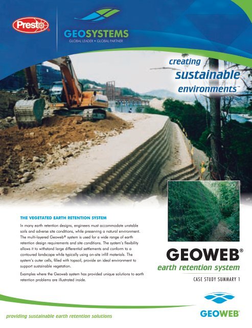
the veGetAteD eArth retention sYsteM<br />
In many earth retention designs, engineers must accommodate unstable<br />
soils and adverse site conditions, while preserving a natural environment.<br />
The multi-layered <strong>Geoweb</strong> ® system is used for a wide range of earth<br />
retention design requirements and site conditions. The system’s flexibility<br />
allows it to withstand large differential settlements and conform to a<br />
contoured landscape while typically using on-site infill materials. The<br />
system’s outer cells, filled with topsoil, provide an ideal environment to<br />
support sustainable vegetation.<br />
Examples where the <strong>Geoweb</strong> system has provided unique solutions to earth<br />
retention problems are illustrated inside.<br />
providing sustainable earth retention solutions<br />
creating<br />
sustainable<br />
environments <br />
GeoWeB ®<br />
earth retention system<br />
CAse study suMMAry 1
case study 1<br />
tAnner/Moffett Creeks • the dalleS, OregOn • fall 1998<br />
awarded 1999 induStrial fabriCS aSSOCiatiOn award Of exCellenCe<br />
The Challenge<br />
A plan to connect two sections of an old highway right-of-way in the<br />
Columbia River Gorge area included a section that would become<br />
part of a 100-mile bike and pedestrian pathway from Portland to The<br />
Dalles. Oregon DOT faced a considerable challenge of designing<br />
a series of switchbacks to gradually bring the bike path from the<br />
highway down to creek level and pass under I-84. Retaining wall<br />
case study 2<br />
The Challenge<br />
Signs that the soil behind an existing aging sheet pile wall supporting<br />
Broadmoor Road and an adjacent railroad track was moving forced<br />
the village of Bayside to seek a solution. Challenges included:<br />
1) building a 9-m (30-ft) high structure across a 56-m (185-ft) wide,<br />
steep, wooded ravine with limited site access, 2) minimizing the size<br />
of the footprint to reduce impact on a stream flowing through the<br />
culverts, and 3) having the ability to support natural vegetation to<br />
blend with the surrounding ravine.<br />
Using granular soil and geogrid layers, a reinforced earth<br />
embankment was built with the <strong>Geoweb</strong> ® system facia and a front<br />
face batter of 0.75h:1v.<br />
The InsTallaTIon<br />
Each 8-cell wide<br />
by 3-cell<br />
long <strong>Geoweb</strong><br />
section was<br />
specified with<br />
a green facia panel and perforated interior cells<br />
to improve drainage and increase frictional<br />
interlock between the cells and the infill. Biaxial<br />
geogrid was sandwiched between the cellular<br />
layers every fourth course as a reinforcement<br />
layer. A trackhoe and clamshell bucket were<br />
Project photos courtesy Soil Stabilization Products Co.<br />
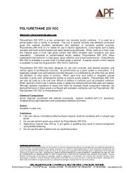
broadmoor road • baySide, wiSCOnSin • September 2000<br />
structures were necessary to<br />
keep the newly steepened<br />
side slopes in place. A<br />
vegetated facia was desired<br />
to blend naturally with an<br />
environment that provides spectacular views of the river and<br />
Cascades. A geocomposite solution combining the <strong>Geoweb</strong> ®<br />
system with high-strength woven geotextile soil reinforcement<br />
was chosen.<br />
The InsTallaTIon<br />
Six wall structures were required, one over 5 m (16 ft) in<br />
height. Green outer face panels blend naturally with the<br />
surrounding landscape. Perforated interior cell walls allowed<br />
drainage of the infill material. To establish vegetative cover<br />
quickly, ODOT hydroseeded the completed walls.<br />
The ResulTs<br />
After installation, a substantial natural spring was discovered<br />
behind one wall. Lower outer facia panels were simply<br />
removed, exposing the perforated interior cell walls and<br />
allowing drainage without damage to the wall structure. A<br />
drainage system was later installed to reduce the potential for<br />
hydrostatic pressure buildup.<br />
used to place infill on the lower<br />
wall layers. On the upper layers,<br />
infill was dropped some 3-3.7 m<br />
(10-12 ft) from the road above<br />
by a front-end loader.<br />
The ResulTs<br />
Project photos courtesy GeoSynthetics, Inc.<br />
The finished structure included a four-pipe culvert to increase<br />
stormwater flow capacity through the embankment. The wall<br />
measured 20 m (65 ft) wide at the base, 56 m (185 ft) wide<br />
at the top with 381 face m2 (4,100 face ft2). The finished<br />
embankment was hydroseeded with a mixture of annual rye<br />
cover, prairie grasses and flowers. All involved parties agreed<br />
that this vegetated geocomposite wall system was a success.
case study 3<br />
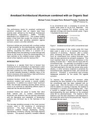
phoenix park resort • kangwOn-dO, kOrea • Summer 1995<br />
The Challenge<br />
Construction in a popular tourist resort area posed several<br />
site challenges, including the building of a retaining wall<br />
structure to protect a cut embankment up to 14 m (46 ft)<br />
high. The rugged mountainous terrain demanded the<br />
embankment have several key characteristics: 1) the ability<br />
to resist the effects of erosion, 2) the flexibility to conform<br />
to anticipated differential settlement, 3) the aesthetic quality<br />
to blend with the natural environment, and 4) the costeffectiveness<br />
to meet strict budget guidelines.<br />
The <strong>Geoweb</strong> ® system met the criteria by: 1) providing a<br />
nearly vertical surface while controlling erosion, 2 remaining<br />
structurally stable<br />
through differential<br />
settlements, 3) allowing<br />
a vegetative facia that<br />
blends in naturally<br />
with the environment,<br />
and 4) meeting project<br />
budget requirements by<br />
completing construction in<br />
only two months.<br />
case study 4<br />
kressview springs • Cambridge, OntariO, Canada • winter 1989<br />
The Challenge<br />
Unstable soils, steep embankments, limited right-of-way<br />
and site access were construction challenges developers<br />
faced during the design and construction of a condominium<br />
embankment situated on the side of a steep river valley.<br />
The project required constructing a 260-m (850-ft) long<br />
driveway embankment rising from grade level at the site<br />
entrance to a maximum height of 11 m (36 ft) at the top.<br />
A 2.5-m (8.2-ft) deep peat deposit under a 30-m (100-ft)<br />
section of the site<br />
created an unstable<br />
area. Removing the<br />
peat and replacing it<br />
with quality foundation<br />
materials was costprohibitive<br />
and would<br />
destroy several large<br />
willow trees along<br />
the stream bank. The<br />
<strong>Geoweb</strong> ® system was<br />
an ideal solution, as<br />
it conforms to steep,<br />
The InsTallaTIon<br />
The retaining wall structures were formed by layering tan-faced<br />
<strong>Geoweb</strong> sections. For soil reinforcement, geogrid or high-strength<br />
woven geotextile layers were placed at required design intervals.<br />
The largest of the structures measures 200 m (650 ft) in length, with<br />
heights varying from 6-14 m (20-46 ft). Slopes range from 1h:8v to<br />
1h:2.5v for all walls.<br />
The ResulTs<br />
The resort owners are pleased with the performance of the<br />
<strong>Geoweb</strong> system and the positive aesthetic appeal of the large<br />
vegetated structure.<br />
contoured landscapes, tolerates<br />
differential settlements, can<br />
support heavy vehicles during<br />
construction, and provides a vegetated facia.<br />
The InsTallaTIon<br />
The site was prepared and <strong>Geoweb</strong> sections were placed, infilled and<br />
compacted. Subsequent layers were placed with a 25 mm (1 in) setback<br />
until the wall height was achieved. At required design intervals,<br />
a geogrid or woven geotextile soil<br />
reinforcement layer was placed.<br />
The ResulTs<br />
The completed geocomposite<br />
embankment totalled 238 m<br />
(780 ft) long and 11 m (36 ft)<br />
high, with a total wall surface of<br />
1,400 face m2 (15,000 ft2). Wall<br />
face batter varied from 1h:2v to<br />
1h:8v. Even after years of exposure<br />
to a northern climate, the <strong>Geoweb</strong><br />
system has performed successfully.<br />
Project photos courtesy E & S Engineering
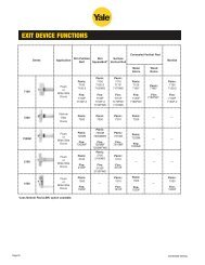
case study 5<br />
kressvieW sPrinGs, PhAse ii • Cambridge, OntariO, Canada • Summer 1998<br />
The Challenge<br />
At the upper end<br />
of the Kressview<br />
property, a cut in<br />
the natural slope<br />
produced a soil face<br />
that was stabilized<br />
10 years earlier<br />
using soil nailing<br />
to hold a geogrid / geotextile layer over the exposed surface. Water<br />
lenses in the embankment had caused significant soil destabilization<br />
and movement – a safety concern for residents. With the successful<br />
application of the <strong>Geoweb</strong> ® wall system on the lower embankment, a<br />
similar solution was proposed to repair the upper level.<br />
The InsTallaTIon<br />
The original 2h:1v slope<br />
was excavated<br />
to a near vertical<br />
cut 10 m (33 ft)<br />
high. The slope<br />
cut was made<br />
with three terraces<br />
2 m (6.5 ft)<br />
wide that were vegetated for aesthetic appeal. During<br />
rehabilitation, the geosynthetic facing and all vegetation<br />
were removed, leaving the soil-nail system intact. The<br />
reconstruction utilized the existing soil nails, replacing<br />
the geosynthetic facia with the layered <strong>Geoweb</strong> system.<br />
The new 9-m (30-ft) high wall system permitted drainage<br />
through the structure’s face while controlling potential soil<br />
movement. At the appropriate lifts, <strong>Geoweb</strong> sections were<br />
attached to the soil nails using a polyester geogrid, steel<br />
pipes and special soil nail heads.<br />
Presto GeosYsteMs’ CoMMitMent – To provide the highest quality products and solutions.<br />
At Presto, we’re committed to helping you apply the most cost-efficient solution to your earth retention needs.<br />
Contact Presto Geosystems or our worldwide network of knowledgeable distributors/representatives for<br />
assistance with your project needs.<br />
PRESTO GEOSYSTEMS<br />
distributed by:<br />
P.O. Box 2399<br />
670 North Perkins Street<br />
Appleton, Wisconsin 54912-2399, USA<br />
P: 920-738-1707<br />
TF: 800-548-3424<br />
F: 920-738-1222<br />
E: info@prestogeo.com<br />
www.prestogeo.com<br />
The ResulTs<br />
In total, 460 m2 (5,000 ft2) of wall face<br />
was reconstructed in three<br />
wall lifts varying in height<br />
from 2-9 m (6-30 ft).<br />
Groundcover plantings<br />
were placed in the open<br />
front facia cells and a<br />
variety of small shrubs<br />
were planted on the<br />
terraces. The developer<br />
and condominium owners<br />
are pleased with the natural<br />
look and stability of the<br />
repaired wall.<br />
Geosystems ® and GeoWeb ® are registered trademarks of Presto Products Co. Creating sustainable environments is a trademark of Presto Products Co. This<br />
information has been prepared for the benefit of customers interested in the <strong>Geoweb</strong> ® earth retention system. It was reviewed carefully prior to publication.<br />
Presto assumes no liability for its accuracy or completeness. Final determination of the suitability of any information or material for the use contemplated, or for<br />
its manner of use, is the sole responsibility of the user.<br />
GW/RW001 JUNE 2008<br />
Printed in the U.S.A. 2008<br />
© 2008 Presto Geosystems<br />
AP-3273 R1