
Create successful ePaper yourself
Turn your PDF publications into a flip-book with our unique Google optimized e-Paper software.
1. SAFETY INSTRUCTIONS<br />
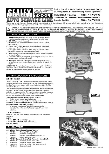
<strong>Instructions</strong> <strong>for</strong>: Petrol Engine Twin Camshaft Setting<br />
/ Locking Tool Kit - (incorporating Vanos Alignment) -<br />
BMW N42 & N46 Engines Model No: VS4800<br />
Associated kit: Camshaft/Carrier Bracket Remover &<br />
Installer Tool Kit Model No: VS4815<br />
Thank you <strong>for</strong> purchasing a Sealey product. Manufactured to a high standard this product will, if used according to these instructions<br />
and properly maintained, give you years of trouble free per<strong>for</strong>mance.<br />
IMPORTANT: PLEASE READ THESE INSTRUCTIONS CAREFULLY. NOTE THE SAFE OPERATIONAL REQUIREMENTS, WARNINGS AND CAUTIONS.<br />
USE THE PRODUCT CORRECTLY AND WITH CARE FOR THE PURPOSE FOR WHICH IT IS INTENDED. FAILURE TO DO SO MAY CAUSE DAMAGE<br />
AND/OR PERSONAL INJURY AND WILL INVALIDATE THE WARRANTY. PLEASE KEEP INSTRUCTIONS SAFE FOR FUTURE USE.<br />
WARNING! Ensure Health and Safety, local authority and general<br />
workshop practice regulations are adhered to when using tools.<br />
DO NOT use tools if damaged.<br />
Maintain tools in good and clean condition <strong>for</strong> best and safest<br />
per<strong>for</strong>mance.<br />
Ensure that a vehicle which has been jacked up is adequately<br />
supported with axle stands.<br />
Wear approved eye protection. A full range of personal safety<br />
equipment is available from your Sealey dealer.<br />
Wear suitable clothing to avoid snagging. Do not wear jewellery and<br />
tie back long hair.<br />
Account <strong>for</strong> all tools, locking bolts, pins and parts being used and do<br />
not leave them in or near the engine.<br />
WARNING! Incorrect or out of phase camshaft timing can result in<br />
contact between valve head and piston crown causing damage to the<br />
engine.<br />
IMPORTANT: These instructions are provided as a guide only. Always<br />
refer to the vehicle manufacturer’s service instructions, or a proprietary<br />
manual, to establish the current procedure and data.<br />
2. INTRODUCTION & APPLICATIONS<br />
2.1 Introduction<br />
The N42 and N46 1.8 & 2.0 twin camshaft petrol engines have Vanos<br />
variable camshaft timing units on both inlet and exhaust camshafts and<br />
the BMW Valvetronic system which varies the timing and the lift of the<br />
inlet valves (Fig.1).<br />
The Valvetronic layout incorporates a conventional inlet camshaft and a<br />
secondary eccentric shaft, with intermediate levers and followers,<br />
activated by a stepper motor. The stepper motor changes the phases of<br />
the eccentric shaft, altering the action of the inlet valves. All these are<br />
housed in a camshaft carrier bracket in the cylinder head.<br />
VS4800 Engine Setting/Locking Tool Kit covers:-<br />
* Engine timing - checking and adjustment<br />
* Vanos Unit - removal, installation and alignment.<br />
VS4815 is an Associated Specialised Tool Kit which, when used in<br />
conjunction with VS4800 Kit, provides:<br />
* <strong>for</strong> removal, installation of camshafts plus dismantling<br />
and re-building of the camshaft carrier bracket / Valvetronic<br />
assembly.<br />
2.2 Applications<br />
BMW N42 and N46 Twin Camshaft Petrol engines with Valvetronic<br />
system in:<br />
BMW:<br />
1 Series (E87) 118i and 120i (04-),<br />
3 Series (E46) 316i/316ti, 318i, 318Ti (01-),<br />
B18/B20 engines.<br />
3. CONTENTS<br />
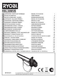
3.1. VS4800 Engine Setting/Locking Tool Kit:<br />
1 VS4801 Flywheel TDC Locking Pin<br />
2 VS4802 Camshaft Turning Tool<br />
3 VS4803 Timing Chain Tensioner Pre-Load Tool<br />
4 VS4804 Vanos Alignment Plate<br />
VS4805 Camshaft Setting Plate Assembly - items 5 to 7:<br />
5 VS4805-1 Camshaft Setting Plate (Inlet)<br />
6 VS4805-2 Camshaft Setting Plate (Exhaust)<br />
7 VS4805-3 Camshaft Setting Plate Securing Screw<br />
-- VS4800/84 Case and Insert<br />
VS4800<br />
VS4815<br />
VS4800 & VS4815 - 1 - 191206
3.2. VS4815 Camshaft/Carrier Bracket Remover & Installer<br />
Tool Kit:<br />
8 VS4814 Torsion Spring Remover/Installer<br />
9 VS4816 Inlet Camshaft Securing Tool (Front)<br />
10 VS4817 Inlet Camshaft Securing Tool (Rear)<br />
11 VS4818 Intermediate Lever Clamp Set (8)<br />
12 VS4819 Camshaft/Carrier Bracket Mounting Fixture<br />
-- VS4815/84 Case and Insert<br />
4. INSTRUCTIONS<br />
SECTION 1: - Use of VS4800 Kit - Engine Timing Checking and<br />
Adjustment, and Vanos Alignment.<br />
4.1 Checking camshaft timing<br />
4.1.1 Camshaft position<br />
Turn the crankshaft, in normal direction of engine rotation, to TDC<br />
No.1 cylinder (ignition), using a wrench on the crankshaft pulley<br />
centre bolt.<br />
Check the timing positions of the camshafts - each camshaft has a<br />
rectangular section at the rear which has a curved edge on top<br />
and a straight edge on the bottom. With the engine in the correct<br />
TDC engine timing position, the curved edge of the rectangles, on<br />
both camshafts, will be uppermost ie. on top (Fig.2).<br />
An additional guide to correct camshaft position, using the exhaust<br />
camshaft, is that in the correct TDC engine timing position, the<br />
recesses in the sections of the exhaust camshaft between the<br />
lobes, will be pointing towards the exhaust manifold (Fig.3).<br />
4.1.2 Crankshaft position<br />
VS4801 Flywheel TDC Locking Pin<br />
Insert VS4801 Flywheel TDC Locking Pin through the datum hole,<br />
which is located underneath the starter motor, and into the timing<br />
hole in the flywheel (Fig.4).<br />
NOTE: The datum hole can be difficult to locate and may be<br />
constricted by dirt/corrosion.<br />
IMPORTANT: On Automatic Transmissions - there is a much<br />
larger hole in the flywheel very near to the timing hole and checks<br />
are required to ensure that this hole has not been selected in<br />
error. With VS4801 Locking Pin inserted, check that the engine will<br />
not rotate back and <strong>for</strong>th when turned using a wrench on the<br />
crankshaft pulley bolt.<br />
4.1.3 Checking VANOS Units:<br />
When the engine is turned off, the Vanos Units on the inlet and<br />
exhaust camshafts usually 'lock' on the camshafts, in their correct<br />
positions. It is essential to check that this has occurred, in order to<br />
avoid incorrect timing adjustment and to check that these units are<br />
in working order.<br />
VS4802 Camshaft Turning Tool<br />
Inlet camshaft:<br />
Insert VS4802 Camshaft Turning Tool into the slot in the<br />
rectangular section at the rear of the INLET camshaft (Fig.5).<br />
Using a spanner on the hexagon of VS4802, check if the camshaft<br />
will rotate. If it does turn, carefully rotate the camshaft against the<br />
direction of rotation, as far as possible, until it 'locks' the Vanos<br />
unit.<br />
NOTE: If the Vanos Unit has 'locked' correctly, the camshaft will not turn.<br />
Exhaust camshaft:<br />
The same procedure applies to the exhaust camshaft EXCEPT<br />
this camshaft should be rotated in the direction of rotation.<br />
NOTE: The exhaust camshaft has a hexagon to accept a spanner<br />
to rotate it but also VS4802 Turning Tool can be used if the<br />
vacuum pump has been removed (Fig.6).<br />
IMPORTANT: If either of the Vanos Units on the camshafts<br />
cannot be 'locked', and are faulty, they must be replaced - see<br />
section 4.3. Removing, Installing and Replacing Vanos Units.<br />
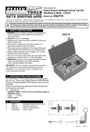
Fig.3<br />
Fig.1<br />
Fig.7<br />
Fig.2<br />
Fig.4<br />
Fig.5 Fig.6<br />
VS4800 & VS4815 - 1 - 191206
4.1.4 Checking timing position<br />
VS4805 Camshaft Setting Plate Assy (<strong>com</strong>prises VS4805-1,<br />
VS4805-2 & VS4805-3)<br />
Place VS4805-1 Camshaft Setting Plate on to the rectangular<br />
section at the rear of the INLET camshaft, and ensure the Plate<br />
rests fully on the surface of the cylinder head (do not insert fixing<br />
bolts). If timing is correct, VS4805-1 Plate should rest on the<br />
cylinder head without any gap, or at most, raised 0.5mm on the<br />
inlet side only (Fig.7).<br />
Place VS4805-2 Camshaft Setting Plate on to the rectangular<br />
section at the rear of the EXHAUST camshaft, and ensure the<br />
Plate rests fully on the surface of the cylinder head (do not insert<br />
fixing bolts).<br />
If timing is correct, VS4805-2 should rest on the cylinder head<br />
without any gap, or at most, raised 1.0mm on the inlet side only<br />
(Fig.8).<br />
If the above position cannot be achieved with the Setting Plates,<br />
then it will be necessary to adjust the timing.<br />
Remove the Camshaft Setting Plates.<br />
4.2 Adjusting camshaft timing<br />
Slacken the bolts of the Vanos Units on the inlet and exhaust<br />
camshafts (Fig.9).<br />
WARNING: These bolts are likely to be tight. It will be<br />
necessary to counter-hold against engine rotation at the<br />
crankshaft pulley centre bolt. Do NOT rely on the Flywheel Pin<br />
to counter-hold when loosening these bolts.<br />
Screw in the bolts to finger-tight only, sufficient so there is no play<br />
or tilt on the units. Ensure that the VS4801 Flywheel TDC Locking<br />
Pin is fitted into the timing hole in the flywheel.<br />
4.2.1 Fitting Camshaft Setting Plates<br />
Place VS4805-1 Camshaft Setting Plate onto the rectangular<br />
section at the rear of the INLET camshaft, ensuring that the curved<br />
edge of the rectangular plate is uppermost. Align the camshaft so<br />
the Setting Plate rests fully on the surface of the cylinder head<br />
(Fig.7).<br />
NOTE: Do not insert fixing bolts at this stage.<br />
Fit VS4805-2 Camshaft Setting Plate on to the rectangular section<br />
at the rear of the EXHAUST camshaft, ensuring that the curved<br />
edge of the rectangular plate is uppermost. Align the camshaft so<br />
the Plate rests fully on the surface of the cylinder head. Screw in<br />
the two fixing bolts and tighten to secure the Setting Plate to<br />
the cylinder head (Fig.10).<br />
Screw in VS4805-3 Securing Screw into Setting Plate VS4805-2<br />
until it presses on Setting Plate VS4805-1 (Fig.11).<br />
Finally, screw in the fixing bolt <strong>for</strong> VS4805-1 and tighten to secure<br />
this Setting Plate to the cylinder head.<br />
4.2.2 Chain Tensioner<br />
VS4803 Timing Chain Tensioner Pre-Load Tool<br />
Remove the timing chain tensioner, and in its place insert VS4803<br />
Tensioner Pre-Load Tool (Fig.12)<br />
Screw in the adjusting screw of VS4803, by hand, until it makes<br />
contact with the tensioner rail but does not apply pressure<br />
(Fig.13).<br />
4.2.3 Vanos Unit alignment<br />
Remove the old bolts of the Vanos Units on the inlet and exhaust<br />
camshafts and fit new bolts. Screw in the bolts to finger-tight only,<br />
sufficient so there is no play or tilt on the units.<br />
VS4804 Vanos Alignment Plate<br />
Fit VS4804 Vanos Alignment Tool to the front of the Units<br />
ensuring that its two location pins enter into the holes in the Vanos<br />
Units and that the Alignment Tool fits fully on to the surface of the<br />
cylinder head (Fig.14).<br />
Screw in the two bolts and tighten to secure VS4804 to the<br />
cylinder head (Fig.15).<br />
Slacken the Vanos Unit bolts half a turn and re-tighten to fingertight.<br />
Attach a suitable torque wrench to the adjusting screw of<br />
VS4803. Turn to apply a pre-load to the tensioner rail of 0.6 Nm<br />
(Fig.16).<br />
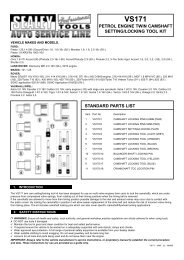
Fig.10<br />
Fig.12<br />
Fig.14<br />
Fig.8<br />
Fig.9<br />
Fig.11<br />
Fig.13<br />
VS4800 & VS4815 - 1 - 191206
Tighten the bolt of the exhaust camshaft Vanos unit to the<br />
specified torque, followed by the bolt of the inlet Vanos Unit,<br />
again, to the specified torque - Torque 20Nm + 90°+ 90° (Fig.17).<br />
4.2.4 Checking engine timing position<br />
Remove the VS4804 Vanos Alignment Tool, unscrew the adjusting<br />
screw of VS4803 and remove the Pre-Load Tool.<br />
IMPORTANT: Install the chain tensioner.<br />
Remove all timing tools and turn the crankshaft twice (at the<br />
crankshaft pulley centre bolt), in normal direction of engine<br />
rotation, returning to TDC engine timing position, No.1 cylinder.<br />
Insert the Flywheel TDC Locking Pin and Camshaft Setting Plates<br />
- to check timing position, follow the procedure as described in<br />
“4.1. Checking camshaft timing”.<br />
4.3 Removing, installing and replacing Vanos Units.<br />
Remove the positioning motor <strong>for</strong> the eccentric shaft by undoing<br />
the nuts retaining the motor on bracket, rotating the shaft<br />
clockwise whilst pulling the motor backwards out of its bracket<br />
(Fig.18). Follow the procedure detailed in “4.1 Checking camshaft<br />
timing” up to and including “4.1.3 Checking procedure - Vanos<br />
Units”. If either of the Vanos Units, on inlet or exhaust camshafts,<br />
cannot be 'locked' and are faulty, they must be replaced.<br />
4.3.1 Removal<br />
Slacken the bolts of the Vanos Units on the inlet and exhaust<br />
camshafts (Fig.9).<br />
WARNING: These bolts are likely to be tight. It will be<br />
necessary to counter-hold against engine rotation at the<br />
crankshaft pulley centre bolt. Do NOT rely on the Flywheel<br />
Pin to counter-hold when loosening these bolts.<br />
Screw in the bolts to finger-tight only, sufficient so there is no play<br />
or tilt on the units. Ensure that the VS4801 Flywheel TDC Locking<br />
Pin is fitted into the timing hole in the flywheel.<br />
Place VS4805-1 Camshaft Setting Plate on to the rectangular<br />
section at the rear of the INLET camshaft, ensuring that the<br />
curved edge of the rectangular plate is uppermost (Fig.7).<br />
Align the camshaft so the Setting Plate rests fully on the surface<br />
of the cylinder head. (Do not insert fixing bolt).<br />
Place VS4805-2 Camshaft Setting Plate on to the rectangular<br />
section at the rear of the EXHAUST camshaft, ensuring that the<br />
curved edge of the rectangular plate is uppermost (Fig.8).<br />
Align the camshaft so the Plate rests fully on the surface of the<br />
cylinder head. Screw in the two fixing bolts and tighten to<br />
secure the Setting Plate to the cylinder head.<br />
Screw in VS4805-3 Securing Screw into Setting Plate VS4805-2<br />
until it presses on Setting Plate VS4805-1 (Fig.11).<br />
Screw in the fixing bolt <strong>for</strong> VS4805-1 and tighten to secure this<br />
Setting Plate to the cylinder head. Remove the timing chain<br />
tensioner (Fig.12),<br />
Fully remove the bolt of the Vanos Unit on the exhaust<br />
camshaft. Lift chain off the sprocket and feed out and remove the<br />
<strong>com</strong>plete Vanos Unit.<br />
Repeat this procedure on the Vanos Unit on the inlet camshaft.<br />
4.3.2 Replacement<br />
WARNING: It is important to note that the Inlet and exhaust<br />
VANOS Units are different. It is essential to keep the parts of<br />
Inlet Unit separate from the Exhaust Unit. Under no<br />
circumstances should the parts be mixed or parts from any<br />
other engine variant be used.<br />
Inlet Unit part is marked "EIN / IN" (Fig.19) and the Exhaust<br />
Unit part marked "AUS / EX" (Fig.20)<br />
4.3.3 Installation<br />
Assemble the Unit of the Inlet camshaft, including the sensor gear<br />
(front plate), and feed on to the inlet camshaft fitting the chain<br />
onto the sprocket. Screw in a new bolt and tighten only so there is<br />
no play or tilting (finger-tight).<br />
Assemble and install the Exhaust camshaft Unit and screw in a<br />
new bolt and tighten only so there is no play or tilting.<br />
IMPORTANT: Press the chain rail, by hand, and ensure the timing<br />
chain is guided within the rail.<br />
Insert VS4803 Tensioner Pre-Load Tool and screw in the adjusting<br />
screw by hand, until it makes contact with the tensioner rail (Fig.13).<br />
Fit VS4804 VANOS Alignment Tool to the front of the Units<br />
ensuring that its two location pins enter into the holes in the<br />
sensor gears and the Tool fits fully onto the surface of the<br />
cylinder head (Fig.21).<br />
Fig.17<br />
Fig.19<br />
Fig.21<br />
Fig.15<br />
Fig.16<br />
Fig.18<br />
Fig.20<br />
Fig.22<br />
VS4800 & VS4815 - 1 - 191206
Screw in the two bolts to secure VS4804 Tool to the cylinder head<br />
and tighten (Fig.15).<br />
Unscrew the bolts of the Vanos Units half turn and then tighten to<br />
finger-tight, ensuring that there is no play or tilting of the Vanos<br />
units.<br />
Attach a suitable torque wrench to the adjusting screw of AST4803<br />
and turn to pre-load the tensioner rail to 0.6 Nm (Fig.16).<br />
Tighten the bolt of the exhaust camshaft Vanos unit to the<br />
specified torque, followed by the bolt of the inlet Vanos Unit,<br />
again, to the specified torque - Torque 20Nm + 90° + 90°. (Fig.17)<br />
4.3.4 Checking engine timing position<br />
Remove VS4804 Alignment Tool,<br />
Unscrew the adjusting screw of VS4803 and remove the Pre-Load<br />
Tool<br />
IMPORTANT: Install the chain tensioner.<br />
Remove all timing tools and turn the crankshaft twice (at<br />
crankshaft pulley centre bolt), in normal direction of engine<br />
rotation, returning to TDC engine timing position, No.1 cylinder.<br />
Insert the Flywheel TDC Locking Pin and Camshaft Setting Plates<br />
to check timing position as described in "4.1 Checking camshaft<br />
timing".<br />
SECTION 2: - use of VS4815 Kit - Removing and Installing<br />
Camshaft/Carrier Bracket<br />
Removal, installation plus dis-assembly and re-building the<br />
camshafts/carrier bracket assembly requires Kit VS4815 used<br />
in conjunction with VS4800 Engine Setting/Locking Tool Kit.<br />
The Carrier, Inlet Camshaft and Eccentric Shaft must be<br />
"clamped" together and removed from the cylinder head as<br />
one assembly, prior to further dis-assembly being carried out<br />
on the workbench fixture.<br />
VS4815 Camshaft/Carrier Bracket Remover & Installer Tool Kit<br />
Comprises<br />
VS4814 Torsion Spring Remover/Installer<br />
VS4816 Inlet Camshaft Securing Tool (Front)<br />
VS4817 Inlet Camshaft Securing Tool (Rear)<br />
VS4818 Intermediate Lever Clamp Set (8)<br />
VS4819 Camshaft/Carrier Bracket Mounting Fixture<br />
4.4 Dis-assembly and removal of the Camshaft/Carrier Bracket<br />
4.4.1 Preparing <strong>for</strong> removal of the Carrier Assembly<br />
Fig.25<br />
Fig.27<br />
IMPORTANT: In order to remove the Inlet camshaft and carrier<br />
assembly the Vanos Units must be removed - <strong>for</strong> procedure, refer<br />
to “4.3 Removing, Installing and replacing Vanos Units" and<br />
follow procedure <strong>for</strong> "Removal".<br />
Fig.29<br />
NOTE: In following procedure <strong>for</strong> removal of the Vanos Units at<br />
this point, the Camshaft Setting Plate Assembly will be installed.<br />
Detach the pulse generator plug <strong>for</strong> the inlet camshaft (Fig.22).<br />
Remove the access plug (<strong>for</strong> lower screw of the chain guide) and<br />
unscrew and remove the chain guide screw (Fig.23 & Fig.24).<br />
NOTE: Ensure screwdriver has a firm attachment to the screw as it<br />
is withdrawn, as screw can fall into the engine.<br />
Unscrew and remove the upper screw of the chain guide (Fig.25).<br />
Remove the chain guide.<br />
NOTE: Guide is held in place by 4 lugs and will need to be carefully<br />
<strong>com</strong>pressed to release the lugs, <strong>for</strong> removal of the guide.<br />
Unscrew and remove the banjo bolt of the oil supply pipe (exhaust<br />
camshaft). (This is so the pipe can be pushed backwards and out<br />
of the way, once the Camshaft Setting Plate Assembly has been<br />
removed), (Fig.26).<br />
Remove <strong>com</strong>plete VS4805 Camshaft Setting Plate Assembly and<br />
push the oil supply pipe towards the rear, approx 20mm (Fig.27).<br />
Rotate the eccentric shaft, via the hexagon, to reduce the amount<br />
of tension on the torsion spring and fit a cable tie to the spring<br />
(Fig.28).<br />
Fig.31<br />
Pull the spring back slightly to lift it off its roller (Fig.29), and then<br />
allow the spring to move slowly <strong>for</strong>ward and passed the roller, to<br />
relieve the tension (Fig.30).<br />
IMPORTANT: Rotate the eccentric shaft, at the hexagon provided,<br />
to minimum stroke position - turn fully clockwise.<br />
Fig.23<br />
Fig.24<br />
Fig.26<br />
Fig.28<br />
Fig.30<br />
VS4800 & VS4815 - 1 - 191206
4.4.2 Securing the camshaft to the carrier bracket assembly<br />
WARNING: Risk of injury and engine damage -<br />
This part of the application involves the removal of the<br />
camshaft carrier bracket and inlet camshaft assembly which<br />
incorporates heavy torsion springs under <strong>com</strong>pression. This<br />
should not be attempted without the use of the specialised<br />
tools in VS4815 Kit, and the service procedure should be<br />
strictly adhered to.<br />
VS4816 Inlet Camshaft Securing Tool (Front)<br />
VS4817 Inlet Camshaft Securing Tool (Rear)<br />
Securing tools VS4816 and VS4817are used to retain the inlet<br />
camshaft to the carrier bracket assembly when it is being removed<br />
from the cylinder head.<br />
Fit VS4816 Camshaft Securing Tool (Front) onto the front of the<br />
inlet camshaft ensuring it locates fully and correctly onto 'lip' of the<br />
cylinder head and secure in place with its locking screw fully<br />
screwed into the internal thread in the end of the camshaft (Fig.31).<br />
Fit VS4817 Camshaft Securing Tool (Rear) on to the back of the<br />
inlet camshaft by screwing its locking bolt into the internal thread in<br />
the end of the eccentric shaft (pinch tight only at first) and locating<br />
the 'domed' nut attached to the end of its locking screw, into the<br />
large countersink of the hole in the rectangular section in the rear<br />
of the inlet camshaft. Tighten the 'domed nut' screw, by hand, to<br />
'lock' the tool onto the camshaft. Tighten the locking bolt into the<br />
eccentric shaft (Fig.32).<br />
4.4.3 Clamping of the Torsion Springs<br />
WARNING: Prior to releasing the nuts retaining the carrier<br />
bracket, the intermediate levers MUST BE secured in position.<br />
VS4818 Intermediate Levers Clamp Set (8 per set)<br />
All 8 x Clamps of VS4818 Set MUST BE fitted. Attach the Clamps<br />
to the bottom of the levers and secure the top of the Clamps onto<br />
the oil supply pipe (Fig.33).<br />
WARNING: Ensure ALL Intermediate Levers are securely clamped.<br />
4.4.4 Removal of the Camshaft/Carrier Bracket<br />
CAREFULLY SELECT WHICH OF THE NUTS MUST BE<br />
RELEASED IN ORDER TO REMOVE THE<br />
CAMSHAFT/CARRIER BRACKET ASSEMBLY.<br />
- 4 x nuts at the front of the bracket (Fig.34)<br />
- 1 x nut on the bracket - exhaust side (Fig.35)<br />
- 4 x nuts on the top of the brackets (arrowed - white) (Fig.36)<br />
- 4 nuts on the inlet side of the bracket (arrowed - black) (Fig.36)<br />
WARNING: DO NOT release the 4 x nuts in the centre on the<br />
inlet side (Marked with "x" in Fig.36).<br />
Release and remove the identified nuts in the order listed above.<br />
For further dismantling, the camshaft/carrier bracket must be<br />
carefully removed from the cylinder head (Fig.37)<br />
NOTE: Used rocker arms must only be re-used in the same position.<br />
DO NOT remove rocker arms on the inlet side.<br />
4.4.5 Bench Mounting the carrier bracket ready <strong>for</strong> dis-assembly of<br />
the camshaft and eccentric shaft.<br />
WARNING: Risk of injury and engine damage -<br />
Further dismantling and removal of the camshafts/eccentric<br />
shaft, intermediate levers etc., involves the removal of torsion<br />
springs. In order to work safely, this procedure MUST BE<br />
carried out on the workshop bench, and the carrier bracket<br />
MUST BE correctly positioned on the Mounting Fixture which<br />
is fixed in a vice. Only the correct tools should be used and<br />
safety glasses worn. The bench/area should be clean and tidy<br />
and prepared to accept the engine parts as they are removed<br />
from the carrier bracket assembly.<br />
VS4819 Camshaft/Carrier Bracket Mounting Fixture<br />
VS4819 Mounting Fixture <strong>com</strong>prises the main base plate and 4 x<br />
pillars (one short pillar and 3 x long pillars) which are fixed by set<br />
screws from underneath the base plate. The base plate is<br />
machined to accept only the correct pillar at each location but<br />
additionally the word "SHORT" on the base plate indicates the<br />
location <strong>for</strong> the short pillar. Assemble the Mounting Fixture and<br />
clamp it in a suitable vice on the workshop bench (Fig.38)<br />
IMPORTANT: INVERT the camshaft/carrier bracket assembly, so<br />
the inlet camshaft is uppermost (Fig.39).<br />
Locate the carrier bracket assembly on to the top of the pillars of<br />
VS4819 Mounting Fixture (Fig.40).<br />
Fig.34<br />
Fig.36<br />
Fig.32<br />
Fig.33<br />
Fig.35<br />
Fig.37 Fig.38<br />
Fig.39 Fig.40<br />
VS4800 & VS4815 - 1 - 191206
4.4.6 Removal of the Torsion Springs<br />
WARNING: Whilst the torsion springs are still installed,<br />
Securing Tools VS4816 and VS4817 which are retaining the<br />
inlet camshaft MUST NOT be removed.<br />
Only after ALL the torsion springs have been de-tensioned<br />
and removed can the inlet camshaft be safely removed.<br />
Remove each of the torsion springs in turn and whilst removing the<br />
spring, also remove the Intermediate Lever. Store in strict order so<br />
they are re-fitted to the same cylinder position when reassembling.<br />
Used Intermediate Levers can only be reused in the<br />
same position.<br />
VS4814 Torsion Spring Remover/Installer<br />
NOTE: To carry out this application, VS4814 and a pair of suitable<br />
Adjustable Pliers (400mm.) such as Sealey AK370 will be<br />
required. These Pliers must be in good working order.<br />
Fit VS4814 Tool to the carrier bracket and secure in place by<br />
inserting its bolt, from the top, through the Tool and through the<br />
Carrier Bracket. Fix with its nut from underneath - tighten nut<br />
(Fig.41).<br />
Slide the Safety Pin fully in to place - through both sides of the<br />
Tool, The Safety Pin will restrict the torsion spring's movement<br />
backwards under tension, when the spring retaining screw is<br />
removed (Fig.42)<br />
Slowly unscrew and remove the torsion spring retaining screw<br />
(Tx30) so that the spring plate pushes against the Safety Pin (Fig.43).<br />
Using a suitable pair of adjustable pliers, such as Sealey AK370, fit<br />
the jaws to span across from the back of tool to the front of the<br />
torsion spring plate (Fig.44).<br />
Carefully relieve the spring pressure off the Safety Pin by slightly<br />
closing the Plier jaws and whilst retaining the jaws in this position,<br />
pull out the Safety Pin (Fig.45).<br />
Carefully and slowly, in a controlled manner, allow the Plier jaws<br />
to open in order to release the torsion spring pressure fully (Fig.46).<br />
Remove the torsion spring together with the associated VS4818<br />
Clamp and intermediate lever (Remember to identify the position of<br />
the lever).<br />
Repeat the procedure to remove each torsion spring in turn.<br />
Once all the torsion springs have been removed, Securing Tools<br />
VS4816 and VS4817 can be removed from the ends of the inlet<br />
camshaft and the inlet camshaft itself can be removed.<br />
For further dismantling, lift the carrier bracket off the VS4819<br />
Mounting Fixture, turn the carrier bracket over and locate it back<br />
onto the pillars of the Fixture to give access to the eccentric shaft.<br />
4.4.7 Re-assembly Notes<br />
Use VS4819 Mounting Fixture on the workshop bench.<br />
NOTE: For Installing the Inlet camshaft, levers, torsion springs etc.,<br />
the carrier bracket must be located on the VS4819 Fixture the<br />
same way up as when the torsion springs/inlet camshaft etc. were<br />
being dis-assembled.<br />
Inlet camshaft - Always check condition of the Plain Compression<br />
rings, they can break easily. To install - carefully pull apart and fit<br />
from the front. Press ring from one side to engage the catch on the<br />
other side (Fig.47).<br />
IMPORTANT: When installing the inlet camshaft, the curved edge<br />
of the rectangular section at the rear of the camshaft MUST BE<br />
pointing downwards in order that the camshaft is in the correct<br />
position when the carrier bracket is installed in the cylinder head<br />
(Fig.48).<br />
NOTE: Ends of Compression rings face upwards<br />
Fit Securing Tools VS4816 and VS4817 to fix each end of the inlet<br />
camshaft to the carrier bracket (Fig.49 and Fig.50).<br />
Lubricate Intermediate Levers with engine oil and install<br />
IMPORTANT: Used Levers MUST BE reused in the same position<br />
from which they were removed. Fit each Intermediate Lever in<br />
turn, securing al l of them in place with VS4818 Clamps.<br />
4.4.8 Installation of Torsion Springs<br />
Re-fit each Torsion Spring in turn.<br />
Place the torsion spring in position with no tension applied.<br />
Fit VS4814 Tool to the carrier bracket and secure in place by<br />
inserting its bolt, from the top, through the Tool and through the<br />
Carrier Bracket. Fix with its nut from underneath - tighten nut.<br />
Using a pair of 400mm adjustable pliers, such as Sealey AK370,<br />
fit the jaws to span across from the back of tool to the front of the<br />
torsion spring plate (Fig.51).<br />
Fig.43<br />
Fig.45<br />
Fig.47<br />
Fig.49<br />
Fig.41<br />
Fig.42<br />
Fig.44<br />
Fig.46<br />
Fig.48<br />
VS4800 & VS4815 - 1 - 191206
Carefully and slowly, in a controlled manner, close the Plier jaws<br />
to <strong>com</strong>press the spring to a position where the spring plate goes<br />
beyond the holes in the Tool which accept the Safety Pin (Fig.52).<br />
Maintain the spring in this position with the Pliers and Slide the<br />
Safety Pin in place - fully through both sides of the Tool, The<br />
Safety Pin will restrict the torsion spring's movement, backwards.<br />
Remove Pliers and screw in the spring retaining screw (Tx30) to<br />
secure the torsion spring in place (Fig.53).<br />
Remove Tool VS4814 and fit to next cylinder/spring position,<br />
repeating the procedure on each torsion spring, in turn.<br />
Install spark plug tubes and ensure rocker arms are secured on<br />
hydraulic lifters.<br />
Install the camshaft/carrier bracket assembly back onto the<br />
cylinder head (Fig.54).<br />
Insert the 8 x nuts along the inlet camshaft line, the 4 x nuts on the<br />
front bearing section and the nut on the bracket (exhaust side)<br />
ALL FINGER-TIGHT only.<br />
Tighten these nuts, from inside outwards to an initial torque of 5Nm<br />
and then tighten down to 10Nm.<br />
Remove the VS4818 Clamps and remove Securing Tools VS4816<br />
and VS4817 from the ends of the inlet camshaft.<br />
Rotate the eccentric shaft fully clockwise and fit the torsion spring<br />
back on to roller (fig.55).<br />
Refit oil line, chain guide etc., to continue re-assembly of cylinder<br />
head, Vanos units etc.<br />
NOTE: It is our policy to continually improve products and as such we reserve the right to alter data, specifications and <strong>com</strong>ponent parts without prior notice.<br />
IMPORTANT: No liability is accepted <strong>for</strong> incorrect use of this product.<br />
WARRANTY: Guarantee is 12 months from purchase date, proof of which will be required <strong>for</strong> any claim.<br />
INFORMATION: For a copy of our latest catalogue and promotions call us on 01284 757525 and leave your full name and address, including postcode.<br />
Sole UK Distributor<br />
Sealey Group,<br />
Bury St. Edmunds, Suffolk.<br />
Fig.52<br />
Fig.54<br />
Fig.50<br />
01284 757500<br />
Web<br />
www.sealey.co.uk<br />
01284 703534 email sales@sealey.co.uk<br />
Fig.51<br />
Fig.53<br />
Fig.55<br />
VS4800 & VS4815 - 1 - 191206