Set the basic position of camshafts - JustAnswer
Set the basic position of camshafts - JustAnswer
Set the basic position of camshafts - JustAnswer

Create successful ePaper yourself
Turn your PDF publications into a flip-book with our unique Google optimized e-Paper software.
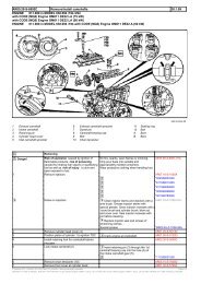
AR05.20-P-6020L <strong>Set</strong> <strong>the</strong> <strong>basic</strong> <strong>position</strong> <strong>of</strong> <strong>camshafts</strong> 12.5.00<br />
ENGINE 137.970 in MODELS 215.378, 220.178 /878<br />
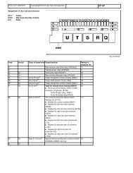
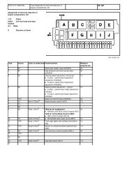
1 Cylinder head 5 Retaining device<br />
A<br />
P05.20-2072-09<br />
Marking <strong>of</strong> camshaft bearing cap<br />
2<br />
3<br />
4<br />
Camshaft bearing cap<br />
Camshaft<br />
Left camshaft adjuster<br />
6<br />
7<br />
8<br />
Right camshaft adjuster<br />
Retaining clip<br />
Screw<br />
B Marking <strong>of</strong> camshaft<br />
Modification notes<br />
12.6.02 Figure modified from 80 Nm to 120 Nm Figure in BA05.10-P-1001-01H for engine *BA05.10-P-1001-01H<br />
137 modified<br />
Remove<br />
1 Remove cylinder head covers AR01.20-P-5014L<br />
2 Remove front cover on right AR01.30-P-5700L<br />
3 Remove cylinder shut<strong>of</strong>f oil pump AR01.30-P-5704L<br />
4 Check timing <strong>of</strong> engine AR05.10-P-6858L<br />
5 Slacken bolt (8) <strong>of</strong> left camshaft adjuster (4) To slacken bolt (8), turn left camshaft so<br />
that <strong>the</strong> retaining device (5) can be installed<br />
free <strong>of</strong> stress at <strong>the</strong> left cylinder head. Before<br />
slackening <strong>the</strong> bolt (8), attach retaining clamp<br />
(7) to <strong>the</strong> left camshaft adjuster (4).<br />
*104589010100<br />
Double open-ended wrench<br />
*137589014000<br />
Holding device<br />
*137589004000<br />
Retaining clamp<br />
6 Take <strong>of</strong>f retaining device (5) at left cylinder<br />
head<br />
7 Slacken bolt (8) <strong>of</strong> right camshaft adjuster (6) To slacken bolt (8), turn right camshaft so<br />
that <strong>the</strong> retaining device (5) can be installed<br />
free <strong>of</strong> stress at <strong>the</strong> right cylinder head.<br />
Before slackening <strong>the</strong> bolt (8), attach<br />
retaining clamp (7) to <strong>the</strong> right camshaft<br />
adjuster (6).<br />
8 Take <strong>of</strong>f retaining device (5) at right cylinder<br />
head<br />
Double open-ended wrench<br />
Holding device<br />
Retaining clamp<br />
9 Position engine to 30° after ignition TDC at Rotate engine at crankshaft in direction<br />
cylinder 1 <strong>of</strong> rotation <strong>of</strong> engine until 30° marking on belt<br />
pulley/vibration damper is aligned with<br />
marking on timing case cover.<br />
*104589010100<br />
*137589014000<br />
*137589004000
11 Remove pins <strong>of</strong> guide rails at left and right Removal: Remove only <strong>the</strong> pins at <strong>the</strong><br />
cylinder head inlet side.<br />
Installation: To facilitate fitting on <strong>the</strong><br />
timing chain. Do not interchange <strong>the</strong> bolts.<br />
Impact extractor<br />
Threaded pin<br />
*116589203300<br />
*116589013400<br />
12 Remove right camshaft adjuster (6) Lift timing chain <strong>of</strong>f camshaft adjuster. AR05.20-P-7201L<br />
*137589004000<br />
Retaining clamp<br />
13 Remove left camshaft adjuster (4) Lift timing chain <strong>of</strong>f camshaft adjuster. AR05.20-P-7201L<br />
*137589004000<br />
Retaining clamp<br />
Install<br />
14 Turn left camshaft into <strong>basic</strong> <strong>position</strong> The <strong>basic</strong> <strong>position</strong> <strong>of</strong> <strong>the</strong> camshaft is only<br />
correct if <strong>the</strong> retaining device (5) can be<br />
installed free <strong>of</strong> stress at <strong>the</strong> left cylinder<br />
head. The marking (A) <strong>of</strong> <strong>the</strong> camshaft<br />
bearing cap (2) must be aligned with <strong>the</strong><br />
marking (B) <strong>of</strong> <strong>the</strong> camshaft (3).<br />
At 30° after ignition TDC at cylinder 1 it is<br />
possible to rotate <strong>the</strong> camshaft without <strong>the</strong><br />
valves touching <strong>the</strong> pistons.<br />
Double open-ended wrench<br />
Holding device<br />
15 Rotate right camshaft into <strong>basic</strong> <strong>position</strong> The <strong>basic</strong> <strong>position</strong> <strong>of</strong> <strong>the</strong> camshaft is only<br />
correct if <strong>the</strong> retaining device (5) can be<br />
installed free <strong>of</strong> stress at <strong>the</strong> left cylinder<br />
head. The marking (A) <strong>of</strong> <strong>the</strong> camshaft<br />
bearing cap (2) must be aligned with <strong>the</strong><br />
marking (B) <strong>of</strong> <strong>the</strong> camshaft (3).<br />
At 30° after ignition TDC at cylinder 1 it is<br />
possible to rotate <strong>the</strong> camshaft without <strong>the</strong><br />
valves touching <strong>the</strong> pistons.<br />
Double open-ended wrench<br />
Holding device<br />
*104589010100<br />
*137589014000<br />
*104589010100<br />
*137589014000<br />
16 Install right camshaft adjuster (6) AR05.20-P-7201L<br />
Fit timing chain onto camshaft adjuster.<br />
Take <strong>of</strong>f retaining clamp.<br />
*137589004000<br />
Retaining clamp<br />
*BA05.20-P-1002-01E<br />
17 Install left camshaft adjuster (4) AR05.20-P-7201L<br />
Fit timing chain onto camshaft adjuster.<br />
Take <strong>of</strong>f retaining clamp.<br />
*137589004000<br />
Retaining clamp<br />
*BA05.20-P-1001-01E<br />
18 Take <strong>of</strong>f retaining devices (5) at left and right *137589014000<br />
cylinder head<br />
19 Install pins <strong>of</strong> guide rails Do not mix up pins.<br />
20 Install chain tensioner AR05.10-P-7800L<br />
*BA05.10-P-1001-01H<br />
21 Check timing <strong>of</strong> engine AR05.10-P-6858L<br />
22 Install front cover on right AR01.30-P-5700L<br />
*BA01.30-P-1001-01G<br />
*BA01.30-P-1002-01G<br />
23 Install oil pump <strong>of</strong> cylinder shut<strong>of</strong>f AR01.30-P-5704L<br />
*BA01.30-P-1003-01G<br />
24 Install cylinder head cover AR01.20-P-5014L<br />
*BA01.20-P-1001-01E<br />
Crankcase ventilation, cylinder head cover<br />
Number Designation Engine<br />
137, 275,<br />
285<br />
BA01.20-P-1001-01E Screw <strong>of</strong> cylinder head cover NM 8<br />
Cylinder head
Number Designation Engine<br />
137<br />
BA01.30-P-1001-01G Front cover on right to cylinder head M6 NM 8<br />
BA01.30-P-1002-01G Bolt <strong>of</strong> guide pulley to front cover on right M8 NM 30<br />
BA01.30-P-1003-01G Cylinder shut<strong>of</strong>f secondary oil pump to left cylinder M6 NM 8<br />
head<br />
Timing chain, chain tensioner<br />
Number Designation Engine<br />
137<br />
BA05.10-P-1001-01H Chain tensioner in cylinder head NM 120<br />
Camshaft<br />
Number Designation Engine<br />
137<br />
BA05.20-P-1001-01E Bolt <strong>of</strong> left camshaft adjuster M14 x 80 1st stage NM 120<br />
2nd stage ° 90<br />
BA05.20-P-1002-01E Bolt <strong>of</strong> right camshaft adjuster M14 x 48 1st stage NM 120<br />
2nd stage ° 90<br />
137 589 00 40 00 137 589 01 40 00 104 589 01 01 00<br />
Retaining clamp Retainer Double open-end wrench<br />
116 589 20 33 00 116 589 01 34 00<br />
Impact extractor Threaded bolt