Engine Cylinder Head Installation - JustAnswer
Engine Cylinder Head Installation - JustAnswer
Engine Cylinder Head Installation - JustAnswer

Create successful ePaper yourself
Turn your PDF publications into a flip-book with our unique Google optimized e-Paper software.
<strong>Engine</strong> <strong>Cylinder</strong> <strong>Head</strong> <strong>Installation</strong><br />
Important: Install the cylinder head without the camshafts.<br />
1. Install the engine cylinder head to the engine block.<br />
2. Install the AIR pump bolt and fir tree fastener from the back of the cylinder<br />
head. Refer to Service Bulletin 06-06-04-016A for further information.<br />
3. Install new cylinder head bolts and tighten the bolts. Refer to <strong>Cylinder</strong> <strong>Head</strong><br />
Replacement in SI.<br />
Camshaft Holding Tool Caution: The camshaft holding tools must be<br />
installed on the camshafts to prevent camshaft rotation. When performing<br />
service to the valve train and/or timing components, valve spring pressure<br />
can cause the camshafts to rotate unexpectedly and can cause personal<br />
injury.<br />
Important: Before installing the camshafts, refer to Camshafts Cleaning and<br />
Inspection in SI.<br />
4. Install the camshafts with the flats up using the J 44221 - Camshaft Holding<br />
Tool. Refer to Camshaft <strong>Installation</strong> in SI.<br />
Notice: Tension must be always kept on the intake side of the timing chain to<br />
properly keep the engine in time. If the chain is loose the timing will be off,<br />
which may cause internal engine damage or set DTC P0017.<br />
Fastener Notice: Use the correct fastener in the correct location.<br />
Replacement fasteners must be the correct part number for that application.<br />
Fasteners requiring replacement or fasteners requiring the use of thread<br />
locking compound or sealant are identified in the service procedure. Do not<br />
use paints, lubricants, or corrosion inhibitors on fasteners or fastener joint<br />
surfaces unless specified. These coatings affect fastener torque and joint
clamping force and may damage the fastener. Use the correct tightening<br />
sequence and specifications when installing fasteners in order to avoid<br />
damage to parts and systems.<br />
Exhaust Camshaft Actuator Notice: The exhaust camshaft actuator must<br />
be fully advanced during installation. <strong>Engine</strong> damage may occur if the<br />
camshaft actuator is not fully advanced. Refer to Camshaft Position Actuator<br />
Diagnosis in SI.<br />
Important: To aid in aligning the actuator to the camshaft, use a 25 mm<br />
(1 in) open end wrench on the hex of the camshaft to rotate. This will ensure<br />
the alignment pin is properly engaged with the camshaft and Hand Tighten<br />
the new exhaust camshaft sprocket bolt.<br />
5. Install the exhaust camshaft actuator/sprocket and chain onto the exhaust<br />
camshaft. Use scribe marks as an alignment guide.<br />
Important: To aid in aligning the intake sprocket to the camshaft, use a<br />
25 mm (1 in) open end wrench on the hex of the camshaft to rotate. This will<br />
ensure the alignment pin is properly engaged with the camshaft and Hand<br />
Tighten the new intake camshaft sprocket bolt.<br />
6. Install the intake camshaft sprocket and chain onto the intake camshaft. Use<br />
scribe marks as alignment guide.<br />
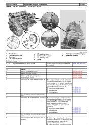
7. Tighten the new intake camshaft sprocket bolt. Refer to the above illustration.<br />
Tighten<br />
Tighten the intake camshaft sprocket bolt to 20 N·m (15 lb ft).<br />
Torque Angle Meter<br />
Use the J 45059 - Torque Angle Meter to rotate the intake camshaft sprocket<br />
bolt an additional 100 degrees.
8. Tighten the new exhaust camshaft actuator sprocket bolt. Refer to the above<br />
illustration.<br />
Tighten<br />
Tighten the exhaust camshaft actuator sprocket bolt to 25 N·m (18 lb ft).<br />
Torque Angle Meter<br />
Use the J 45059 - Torque Angle Meter to rotate the exhaust camshaft<br />
actuator sprocket bolt an additional 135 degrees.<br />
9. Install both upper timing chain tensioner shoe bolts.<br />
Tighten<br />
Tighten the tensioner shoe bolts to 25 N·m (18 lb ft).<br />
10. Install both upper cylinder head access hole plugs to the front of the cylinder<br />
head.<br />
Tighten<br />
Tighten the plugs to 5 N·m (44 lb in).
11. Remove the J 44221 - Camshaft Holding Tool from the back of the camshafts.<br />
Refer to the above illustration.<br />
Notice: Ensure that the wedge tool is removed from the engine prior to<br />
rotation. If the wedge tool is not removed, engine damage will result.<br />
12. Install the handle of the EN-48464 - Lower Timing Chain Tensioner Holding<br />
Tool and remove the wedge portion of the tool from the engine. Refer to the<br />
above illustration.<br />
Important: It is critical that the engine is at TDC and not a couple of degrees<br />
off. If in doubt, repeat this step.
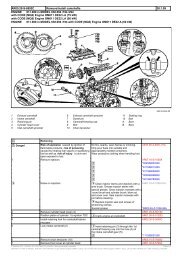
13. Rotate the engine clockwise by hand two complete revolutions to TDC #1 on<br />
the compression stroke. Refer back to step number 40 (Perform the Following<br />
Service Timing Procedure) in this bulletin. If you go past TDC, rotate the<br />
engine back approximately 45 degrees before TDC and then rotate clockwise<br />
up to TDC to ensure that the timing chain is tight (no slack) between the<br />
crank sprocket and the timing gears. Refer to the above illustration.<br />
View A
View B<br />
Important: Do Not use the J 44221 - Camshaft Holding Tool , installed to the<br />
back of the camshafts, as a method to verify timing.<br />
14. Both intake and exhaust camshaft flats should be facing up and flat with the<br />
cylinder head. If the J 44221 - Camshaft Holding Tool is used to verify cam<br />
timing, you could be off approximately one tooth and cause DTC P0017 to<br />
set. Refer to the above illustration View A . Refer to the above illustration<br />
View B (1) showing worn out Camshaft Holding Tool and call out (2) showing<br />
a new Camshaft Holding Tool. If a worn or new J 44221 - Camshaft Holding<br />
Tool is used to verify timing, the timing will be off.<br />
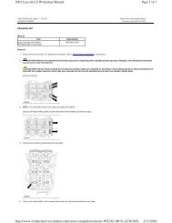
View A
15. To verify timing, set a straight edge across the flats of the camshafts. Refer<br />
to the above illustration View A . Both camshaft flats should be flat. there<br />
may be some variation of build and the straight edge may not lay perfectly<br />
flat across back of the camshafts. If one or both camshaft flats are off, then<br />
the timing is off. Refer to the above illustration View A (1). Repeat step<br />
procedure 15 and recheck. If the camshaft flats are still not flat, the camshaft<br />
timing will have to be reset. This may require removal and reinstallation of<br />
one or both camshaft sprockets. Refer to step #41 in this bulletin.<br />
16. Install (1 long and 2 short ) cylinder head bolts next to the exhaust and<br />
intake timing chain tensioner shoes and tighten the bolts. Refer to <strong>Cylinder</strong><br />
<strong>Head</strong> Replacement in SI.<br />
17. Position the upper timing chain guide to the cylinder head. Apply threadlocker<br />
(Red High Strength), P/N 89021297 (in Canada, use 10953488), to the upper<br />
timing chain guide bolt threads.<br />
18. Install the upper timing chain guide bolts.<br />
Tighten<br />
Tighten the bolts to 10 N·m (89 lb in).<br />
19. Install the upper radiator hose and clamp to the cylinder head.<br />
20. Clean and inspect the camshaft cover. Refer to Camshaft Cover Cleaning and<br />
Inspection in SI.<br />
21. Install a NEW camshaft cover seal and NEW ignition control module seals to<br />
the cam cover. Position the camshaft cover to the cylinder head.<br />
22. Install the camshaft cover bolts.<br />
Tighten<br />
Tighten the bolts to 10 N·m (89 lb in).<br />
23. Check the gap on all of the spark plugs. The gap should be 1.08 mm<br />
(0.042 in). Tighten all of the spark plugs.
Tighten<br />
Tighten the spark plugs to 18 N·m (13 lb ft).<br />
24. Install the ignition coils into the camshaft cover.<br />
25. Install the ignition coil bolts.<br />
Tighten<br />
Tighten the bolts to 10 N·m (89 lb in).<br />
26. Reposition the exhaust manifold to the cylinder head and install the exhaust<br />
manifold bolts to the cylinder head. Refer to Exhaust Manifold Replacement in<br />
SI.<br />
27. Install a NEW A.I.R. injection gasket, then the cover and pipe studs to the<br />
cylinder head.<br />
Tighten<br />
Tighten the pipe studs to 25 N·m (18 lb ft).<br />
28. Install ground strap to cylinder head to exhaust manifold.<br />
29. Install the exhaust manifold heat shield to the exhaust manifold.<br />
30. Apply anti-seize, GM P/N 12371386 (in Canada, 89021945) to the exhaust<br />
manifold heat shield nuts.<br />
31. Install the exhaust manifold heat shield nuts.<br />
Tighten<br />
Tighten the nuts to 10 N·m (89 lb in).<br />
32. Install the intake manifold to the cylinder head. Refer to Intake Manifold<br />
Replacement in SI. Raise the vehicle and install the blind intake manifold<br />
bolts from the left front wheelhouse access.<br />
33. Reposition the engine wiring harness bracket to the engine and harnesses.<br />
Install the engine wiring harness bracket bolts.<br />
Tighten<br />
Tighten the bracket bolts to 10 N·m (89 lb in).<br />
34. Install the left front wheelhouse panel. Refer to Wheelhouse Panel<br />
Replacement (Front) in SI.<br />
35. Install the left wheel and tire. Refer to Tire and Wheel Removal and<br />
<strong>Installation</strong> in SI.<br />
36. Refill the engine oil. Refer to Capacities - Approximate Fluid in SI.<br />
37. Install the lower radiator hose if removed.<br />
38. Lower the vehicle.<br />
39. Install the cross-vehicle wiring harness connectors to the following<br />
components:<br />
• Install PCM engine harness connectors to PCM<br />
• Install PCM/Bracket to intake manifold.<br />
• Map Sensor<br />
• Ignition Coils
• Harness clamps at power steering pump<br />
• Wiring harness fastener at right front inner fender<br />
• Throttle Body<br />
• Camshaft Sensors<br />
• Exhaust Camshaft Actuator<br />
• Fuel Injectors<br />
• HO2S #1<br />
50. Install the PCV pipes to the intake manifold. Refer to Crankcase Ventilation<br />
Hoses/Pipes Replacement in SI.<br />
51. Reposition the oil indicator (dipstick) tube and tighten the bolt to the intake<br />
manifold. Refer to Oil Level Indicator and Tube Replacement Removal<br />
Procedure in SI.<br />
52. Reposition the Fuel/ EVAP lines to the intake manifold retainer. Refer to<br />
Evaporative Emission Hoses/Pipes Replacement - <strong>Engine</strong> in SI.<br />
53. Install the following components. For installation and bolt tightening<br />
procedures, refer to the following SI documents.<br />
• P/S pump bolts. Refer to Power Steering Pump Replacement in SI.<br />
• Generator. For further installation information, refer to Generator<br />
Replacement in SI.<br />
• A/C compressor hose/pipe bracket clamp for the engine lift bracket. Refer<br />
to <strong>Engine</strong> Lift Bracket Replacement in SI.<br />
• Drive Belt. For further installation information, refer to Drive Belt<br />
Replacement in SI.<br />
57. Install the negative battery cable.<br />
58. Install the air induction assembly. Refer to Air Cleaner Resonator and Outlet<br />
Duct Replacement in SI.<br />
59. Refill with NEW engine oil. Refer to Capacities - Approximate Fluid in SI.<br />
60. Refill with NEW coolant. Refer to Draining and Filling Cooling System (Vac-N-<br />
Fill) in SI.<br />
61. Install the air cleaner resonator, the outlet duct and the air cleaner assembly.<br />
62. Remove the fender covers.<br />
63. Remove the protective covering from the front of the vehicle.<br />
64. Install the scan tool and start the engine.<br />
• Refer to Air Cleaner Resonator and Outlet Duct Replacement Removal<br />
Procedure in SI.<br />
• Refer to Air Cleaner Assembly Replacement in SI.<br />
• Check for DTCs.<br />
• Road test the vehicle. DTC P0017 is a Type B diagnostic code. Three<br />
consecutive ignition key cycles must be performed during the road test with<br />
a minimum of a one minute run time between key cycles to verify that a<br />
DTC P0017 did not set. For further information on DTC P0017, refer to SI.
Parts Information<br />
Important: The 2006 and newer cylinder head and related components will not<br />
work on 2002-2005 engines.<br />
Refer to the parts catalog when ordering a cylinder head, related components and<br />
gaskets. All replacement cylinder heads have been upgraded with the new materials.<br />
Condition/Concern:<br />
Depending on the model year, a P0016 or P1345 may be encountered after internal<br />
engine repairs that required resetting of the timing chain tensioner or removal and<br />
installation of the exhaust camshaft actuator sprocket. This may be the result of a<br />
mistimed engine or damaged exhaust camshaft actuator.<br />
Recommendation/Instructions:<br />
If this concern is encountered and the SI diagnostics do not isolate the cause, review<br />
the following information and inspect for a damaged exhaust camshaft actuator or<br />
mistimed engine as necessary:<br />
• The spline style exhaust camshaft actuator used on 2004 model year and earlier<br />
4.2L engines is designed to operate between 25 degrees of retard and 0 degrees<br />
(full advance/rest/clockwise position). There is a stop tab inside of the camshaft<br />
actuator that prevents the exhaust cam from advancing beyond the rest position<br />
under normal operating conditions. This tab can bend if the exhaust<br />
cam/actuator is forced to rotate beyond the rest position (full advance/full<br />
clockwise) during internal engine repairs. If this occurs, it may be noted that the<br />
reluctor portion of the actuator is a few degrees more advanced (clockwise) than<br />
a known good one. With the actuator sprocket in place and the #1 piston at top<br />
dead center, it may be noted that the rear cam flat of the exhaust cam is not<br />
flat when compared with the rear cam flat of the intake cam. Upon further<br />
inspection, it may also be noted that the word Delphi that is on the cam reluctor<br />
portion of the actuator is slightly rotated toward the driver side even though the<br />
intake cam flat is flat. If this is suspected to be the cause of this concern, it will
e necessary to replace the exhaust camshaft actuator again, taking care not to<br />
damage it upon reassembly. As mentioned in SI, do not force the camshaft<br />
actuator to rotate clockwise upon assembly. If it does not move easily, it is<br />
already fully advanced. New camshaft actuators are already packaged in the<br />
fully advanced (clockwise) position. This type of damage should not occur on<br />
2005 model year and newer 4.2L engines because they are equipped with a<br />
vane style exhaust camshaft actuator, which is designed differently than the<br />
spline style actuator.<br />
• If the timing chain tensioner had to be reset, this concern could be the result of<br />
incorrect cam to crank timing. As the timing chain tensioner is released, chain<br />
slack between the crankshaft and tensioner is eliminated. As the slack is<br />
eliminated, it is very easy for the timing chain to shift one tooth at the<br />
crankshaft sprocket without being noticed by the technician. If this occurs, it is<br />
unlikely to isolate the incorrect cam to crank timing without removing the front<br />
cover. When properly timed, the timing marks should line up as shown below<br />
once every 14 crankshaft revolutions with the #1 piston at top dead center. If all<br />
3 of these timing marks never line up at the same time, retime the engine by<br />
following SI procedures.<br />
Condition/Concern:
Some 2002 - 2004 models that are equipped with the 4.2L (VIN S - RPO LL8) engine<br />
may experience a SES Light due to a P0016 or P1345 DTC and a possible rough idle.<br />
Recommendation/Instructions:<br />
If the SI diagnostics do not isolate a cause, the following information may help:<br />
• Control of the Cam Phaser Actuator solenoid is inhibited when a P0016 (04<br />
Model Year) or P1345 (02 - 03 Model Year) DTC is stored.<br />
• If this DTC started after recent internal engine repairs, inspect for proper engine<br />
mechanical timing. With the camshaft cover removed and the #1 cylinder at top<br />
dead center, make sure that the darkened chain links are lined up with the<br />
alignment marks on the exhaust and intake cam sprockets. At this point, J44221<br />
should fit over the rear cam flats and the word Delphi (on the front of the Cam<br />
Phaser Actuator sprocket) should be parallel with the front edge of the cylinder<br />
head. Note: It may take up to 14 crankshaft revolutions before all timing<br />
alignment marks line up with each other.<br />
• <strong>Engine</strong>s built after 2/5/01 include a thin friction washer (P/N 12573950)<br />
between the dampener and the crank gear and the torque specification was<br />
increased to 110 ft-lbs plus 180 degrees to prevent crankshaft gear and<br />
alignment pin damage. If there is any history of the crank dampener bolt ever<br />
being loose, the crankshaft gear and alignment pin may be damaged, which can<br />
cause these DTCs.<br />
• If a P0016 or P1345 is resetting without any engine performance concerns but<br />
the SI diagnostics and the above information did not isolate a cause for the DTC,<br />
replace the Cam Phaser Actuator sprocket.