PETROL ENGINE TWIN CAMSHAFT SETTING ... - Tooled-Up.com
PETROL ENGINE TWIN CAMSHAFT SETTING ... - Tooled-Up.com
PETROL ENGINE TWIN CAMSHAFT SETTING ... - Tooled-Up.com

You also want an ePaper? Increase the reach of your titles
YUMPU automatically turns print PDFs into web optimized ePapers that Google loves.
VEHICLE MAKES AND MODELS.<br />
VS171<br />
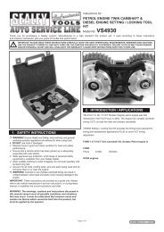
<strong>PETROL</strong> <strong>ENGINE</strong> <strong>TWIN</strong> <strong>CAMSHAFT</strong><br />
<strong>SETTING</strong>/LOCKING TOOL KIT<br />
FORD:<br />
Fiesta 1.25,1.4 (95-) Escort/Orion 1.6, 1.8i 16v (92-). Mondeo 1.6, 1.8, 2.0 16v (93-).<br />
Fiesta 1.8-XR2i/Rs 1800 16V.<br />
HONDA:<br />
Civic 1.6 VTi Accord (90-)/Prelude 2.0 16v (-90). Accord/Prelude 2.3i (93-), Prelude 2.2. V-Tec Sohc Appl: Accord 1.8, 2.0, 2.2, (-93), 2.0i (93-),<br />
Shuttle 2.2i.<br />
LAND ROVER: Discovery MPi 2.0 16V (93-), 20T4 engine.<br />
MAZDA: 121.1.25.<br />
ROVER:<br />
Metro GTa/GTi 16V K16 (-95), 214, 414 K16 (89-). 216,416, GTi 16v (-95) D16A9 engine. 216,416 K16 (95-), MGF 1.8 MPi/VVC (95-). 220 M16<br />
(-92), 220/Turbo T16 (92-), 420 M16 (-92), 420 T16 (92-), 320/Turbo M16 (-91) 820/Turbo T16 Vitesse Turbo (91-). 620 Ti (94-),623 (93-).<br />
SOHC application 820 8V (M8). SOHC Application 618/620 (93-).<br />
VAUXHALL/OPEL:<br />
Astra 2.0 16V Cavalier 2.0 16V Calibra 2.0 16V, early engines (-92) with large cam sprockets. Astra 1.8/2.0 16V, Cavalier 2.0 16V, Calibra 2.0<br />
16V/Turbo.Omega-B 1.4/1.6 16V, Tigra 1.4/1.6 16V, Astra-F 1.6 16V, Vectra 1.6 16V (94-). Vectra 1.8/2.0 16V (95-). Omega 2.0, Sintra 2.2.,<br />
Frontera 2.2. Astra 2.0.<br />
1. INTRODUCTION<br />
STANDARD PARTS LIST<br />
Item Part No Description<br />
1 VS170/1 <strong>CAMSHAFT</strong> LOCKING PINS 6.8MM (PAIR)<br />
2 VS170/2 <strong>CAMSHAFT</strong> LOCKING PINS 5MM (PAIR)<br />
3 VS170/3 <strong>CAMSHAFT</strong> <strong>SETTING</strong>/LOCKING PLATE<br />
4 VS170/4 <strong>CAMSHAFT</strong> LOCKING TOOL (LIGHT GREY)<br />
5 VS170/5 <strong>CAMSHAFT</strong> LOCKING TOOL (ORANGE)<br />
6 VS170/6 <strong>CAMSHAFT</strong> LOCKING TOOL (BLACK)<br />
7 VS170/8 <strong>CAMSHAFT</strong> LOCKING TOOL (BROWN)<br />
10 VS170/10 BALANCER SHAFT LOCKING PIN<br />
8 VS170/12 <strong>CAMSHAFT</strong> LOCKING TOOL (YELLOW)<br />
9 VS170/17 <strong>CAMSHAFT</strong> LOCKING TOOL (BLUE)<br />
11 VS170/18 CRANKSHAFT TDC LOCATION PIN<br />
The VS171 twin cam setting/locking tool kit has been designed for use on multi-valve engines (twin cam) to lock the camshafts, which are under<br />
pressure from <strong>com</strong>pressed valve springs, from rotating out of their timing positions when the timing belt is removed.<br />
If the camshafts are allowed to move from their timing position possible damage to the inlet and exhaust valves may occur due to contact with<br />
the piston crown. By locking the camshafts in position it will allow easier replacement of the drive belt and reduce the risk of incorrect valve timing<br />
from taking place. The kit includes camshaft locking pins which can also cover specific crankshaft/flywheel locking applications.<br />
2. SAFETY INSTRUCTIONS<br />
p WARNING! Ensure all health and safety, local authority, and general workshop practice regulations are strictly adhered to when using tools.<br />
7 DO NOT use tools if damaged.<br />
3 Maintain the tool in good and clean condition for best and safest performance.<br />
3 If required ensure the vehicle to be worked on is adequately supported with axle stands, ramps and chocks.<br />
3 Wear approved eye protection. A full range of personal safety equipment is available from your Sealey dealer.<br />
3 Wear suitable clothing to avoid snagging. Do not wear jewellery and tie back long hair.<br />
3 Account for all tools and parts being used and do not leave them near the engine.<br />
IMPORTANT: Always refer to the vehicle manufacturer’s service instructions, or proprietory manual to establish the current procedure<br />
and data. These instructions for use are provided as a guide only.<br />
VS171 - 0869 - (2) - 060900
3. APPLICATIONS<br />
FORD: Fiesta 1.25,1.4 (95-) VS171/3<br />
Escort/Orion 1.6, 1.8i 16v (92-). VS171/18<br />
Mondeo 1.6, 1.8, 2.0 16v (93-). Fiesta 1.8-XR2i/Rs 1800 16V. VS171/3<br />
4. OPERATING INSTRUCTIONS<br />
HONDA: Civic 1.6 VTi Accord (90-)/Prelude 2.0 16v (-90). VS171/2<br />
Accord/Prelude 2.3i (93-), Prelude 2.2. V-Tec VS171/10<br />
SOHC Appl: Accord 1.8, 2.0, 2.2, (-93), 2.0i (93-), Shuttle 2.2i. VS171/10<br />
LAND ROVER: Discovery MPi 2.0 16V (93-), 20T4 engine. VS171/1 & VS171/5<br />
MAZDA: 121.1.25. VS171/3 & VS171/18<br />
ROVER: Metro GTa/GTi 16V K16 (-95), 214, 414 K16 (89-). VS171/6<br />
216,416, GTi 16v (-95) D16A9 engine, VS171/2<br />
216,416 K16 (95-), MGF 1.8 MPi/VVC (95-). VS171/6<br />
220 M16 (-92), 220/Turbo T16 (92-), 420 M16 (-92), VS171/5 & VS171/1<br />
420 T16 (92-), 320/Turbo M16 (-91) 820/Turbo T16 Vitesse Turbo (91-).<br />
620 Ti (94-), VS171/1 & VS171/5<br />
623 (93-). VS171/10<br />
SOHC application 820 8V (M8). VS171/1 & VS171/6.6 (Optional)<br />
SOHC Application 618/620 (93-). VS171/10<br />
VAUXHALL/OPEL: Astra 2.0 16V Cavalier 2.0 16V Calibra 2.0 16V, VS171/8<br />
Early engines (-92) with large cam sprockets. VS171/8<br />
Astra 1.8/2.0 16V, Cavalier 2.0 16V, Calibra 2.0 16V/Turbo. VS171/4<br />
Omega-B 1.4/1.6 16V, Later engines (93-), with small cam sprockets. VS171/4<br />
Corsa-B 1.4/1.6V, Tigra 1.4/1.6 16V, Astra-F 1.6 16V, Vectra 1.6 16V (94-). VS171/17<br />
Vectra 1.8/2.0 16V (95-). Omega 2.0, Sintra 2.2., Frontera 2.2. Astra 2.0. VS171/12<br />
Ensure safety instructions and the manufacturer’s service instruction are adhered to.<br />
These instructions are provided as a guide only.<br />
For timing belt removal, renewal and refitting, it is often necessary to lock the engine to its stated timing<br />
position marks. Vehicle manufacturers use various methods to achieve this important retention of engine timing<br />
position during this application.<br />
3.1. VS171/1 & VS171/2 <strong>CAMSHAFT</strong> LOCKING PINS - Multi application use, see chart.<br />
When called for in the vehicle manufacturers instructions, the twin camshafts are locked in position,<br />
with the timing marks aligned to those on the casing/cover by the use of two locking pins. This method<br />
of locking is achieved by inserting the correct pins, of a specific diameter, for each camshaft. These<br />
are usually located through assigned holes in the camshaft housing thus engaging and locking<br />
the camshafts in position (fig 1).<br />
Locking pins can also be used to lock the crankshaft in its timing position. When the vehicle manufacturer<br />
calls for this action, the crankshaft is locked in place by inserting the correct diameter locking pin through<br />
a hole in the gearbox mounting back plate to engage a corresponding hole in the flywheel (fig 2).<br />
3.2. VS171/3 <strong>CAMSHAFT</strong> <strong>SETTING</strong>/LOCKING PLATE - Ford, Mazda.<br />
On particular Ford and Mazda twin cam engines (see applications), VS171/3 setting plate is used to lock both<br />
camshafts in their correct positions via a slot at the rear of the camshafts (fig 3 over page).<br />
On these applications it is important to ensure that the crankshaft timing marks are aligned, and that<br />
the VA171/3 setting plate is in position on the camshafts. The tensioner can then be slackened and vibration<br />
damper and timing belt removed. With the setting plate locking the camshafts in position the sprockets<br />
can be loosened using a flange holding wrench. DO NOT USE THE <strong>SETTING</strong> PLATE TO COUNTER<br />
THE UNDOING OF THE SPROCKET BOLT. A HOLDING WRENCH MUST BE USED.<br />
Providing the crankshaft timing marks are aligned, a new belt can be fitted in an anti-clockwise direction.<br />
The tensioner should now contact the belt by spring action only and again using a flange holding wrench<br />
the camshaft sprockets are re-tightened (67-72Nm). Remove the setting/locking plate, refit damper and tighten<br />
tensioner. Rotate the engine two revolutions and and re-check that all timing marks align. Re-check camshaft<br />
position by ensuring that the setting/locking plate can be easily inserted in its slot. If not, re-check<br />
the tensioning procedure again.<br />
fig 1<br />
fig 2<br />
fig 3<br />
VS171/11 Can<br />
be required<br />
according<br />
to sprockets<br />
fitted<br />
(-92). Optional<br />
not in kit.<br />
VS171 - 0869 - (2) - 060900
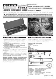
VS171/18 CRANKSHAFT TDC LOCATION PIN - Ford and Mazda.<br />
The VS171/18 crankshaft TDC location pin is used on specific Ford/Mazda twin cam engines, in conjunction<br />
with the VS171/3 camshaft setting and locking plate to ensure correct TDC position. Remove the engine blanking plug to allow VS171/18 to be<br />
screwed into position and then carefully rotate the crankshaft until<br />
the web rests against the pin (fig 4).<br />
Insert the VS171/3 camshaft setting/locking plate to also ensure that correct positioning of the camshaft<br />
is maintain during belt renewal.<br />
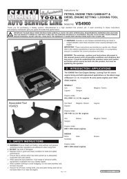
VS171/4, VS171/5, VS171/6, VS171/8, VS171/12 and VS171/17 <strong>CAMSHAFT</strong> LOCKING TOOLS - Multi application use.<br />
These precision formed tools are colour-coded for model use identification. They are used<br />
on any applications and are inserted between the two camshaft sprockets, locating firmly<br />
into the gear teeth of the sprockets. This locks the sprockets in position and prevents them<br />
from rotating out of their timed position when the timing belt is removed (fig 5).<br />
It is essential to ensure the camshaft timing marks align before inserting a locking tool.<br />
The camshaft locking tool then holds the sprockets in their timing position.<br />
NOTE: Vehicle manufacturers put cam timing marks in various positions according to the engine model.<br />
For example, marks can be at the top of the sprockets aligned to the belt cover (3A),<br />
or aligned with upper edge of the cylinder head (3B). It is important to clearly establish<br />
the position of these marks.<br />
It may also be necessary to have the crankshaft “locked” in it’s timing position at this stage.<br />
When installing a new timing belt, it is usual to start at the crankshaft and once the belt<br />
is fitted and lightly tensioned the locking tools are removed and the crankshaft turned<br />
two revolutions by hand. All timing marks must re-align exactly when returning to the timed<br />
position. The locking tools are re-inserted to finalise tensioning and then remove prior<br />
to a further two crankshaft revolutions and a re-checking to ensure all timing<br />
marks align correctly.<br />
NOTE: It is equally important to carefully check each vehicle manufacturers advice on belt<br />
tensioner position as this may differ between new and used belts.<br />
VS171/10 BALANCER SHAFT LOCKING PIN - Honda and Rover.<br />
Certain Honda and Rover engines have balancer shafts connected to the crankshaft pulley<br />
by a balancer shaft belt. During removal and refitting of the timing belt the balancer shaft belt<br />
is removed. It is therefore necessary to refit this belt after renewal and refitting of the timing belt.<br />
Once the new timing belt is fitted correctly, and the crankshaft, flywheel and camshaft timing<br />
marks correctly aligned, the tensioner arm should be locked.<br />
The balancer shaft plug is removed in order to insert VS171/10 balancer shaft locking pin.<br />
The rear balancer shaft sprocket is turned until the pin locks into the hole in the shaft.<br />
The timing marks of the front balancer shaft are aligned and crankshaft pulley removed.<br />
Fit belt, loosen tension, and remove the locking pin. Refit the plug to 30Nm.<br />
The crankshaft pulley is installed and rotated in full turn anti-clockwise before unlocking and<br />
tightening the tensioner.<br />
Re-tighten crankshaft pulley to manufacturers specified torque.<br />
fig 4<br />
fig 5<br />
NOTE: It is our policy to continually improve products and as such we reserve the right to alter data, specifications and <strong>com</strong>ponent parts<br />
without prior notice.<br />
IMPORTANT: No liability is accepted for incorrect use of this product.<br />
WARRANTY: Guarantee is 12 months from purchase date, proof of which will be required for any claim.<br />
INFORMATION: Call 01284 757525 for our catalogue & promotions. Leave your full name, address & postcode.<br />
Sole UK Distributor,<br />
Sealey Group, Bury St. Edmunds, Suffolk.<br />
01284 757500 E-mail: sales@sealey.co.uk<br />
01284 703534<br />
3B<br />
Flywheel<br />
pulley<br />
VS171 - 0869 - (2) - 060900