Petrol engine twin Camshaft & Diesel engine ... - Tooled-Up.com
Petrol engine twin Camshaft & Diesel engine ... - Tooled-Up.com Petrol engine twin Camshaft & Diesel engine ... - Tooled-Up.com
Page 1 of 4 Instructions for: Petrol engine twin Camshaft & Diesel engine setting / loCking tool kit Model No: Vs4930 Thank you for purchasing a Sealey product. Manufactured to a high standard this product will, if used according to these instructions and properly maintained, give you years of trouble free performance. IMPORTANT: Please reaD these instrUCtions CarefUllY. note the safe oPerational reQUirements, warnings anD CaUtions. Use the ProDUCt CorreCtlY anD with Care for the PUrPose for whiCh it is intenDeD. failUre to Do so maY CaUse Damage anD/or Personal inJUrY anD will inValiDate the warrantY. Please keeP instrUCtions safe for fUtUre Use. 1. safetY instrUCtions warning! Ensure Health and Safety, local authority and general workshop practice regulations are adhered to when using tools. Do not use tools if damaged. Maintain tools in good and clean condition for best and safest performance. Ensure that a vehicle which has been jacked up is adequately supported with axle stands. Wear approved eye protection. A full range of personal safety equipment is available from your Sealey dealer. Wear suitable clothing to avoid snagging. Do not wear jewellery and tie back long hair. Account for all tools, locking bolts, pins and parts being used and do not leave them in or near the engine. warning! Incorrect or out of phase camshaft timing can result in contact between valve head and piston crown causing damage to the engine. IMPORTANT: These instructions are provided as a guide only. Always refer to the vehicle manufacturer’s service instructions, or a proprietary manual, to establish the current procedure and data. WARNING: The warnings, cautions and instructions discussed in this manual cannot cover all possible conditions and situations that may occur. It must be understood that common sense and caution are factors which cannot be built into this product, but must be applied by the operator. 2. introDUCtion / aPPliCations The Ford 1.6 16v. Ti VCT Duratec (Sigma) petrol engine was first introduced in the Ford Focus in 2004. The engine has variable camshaft timing (VCT) on both the inlet and exhaust camshafts. VS4930 Setting / Locking Tool Kit provides the timing tools required for timing belt replacement applications PLUS to cover VCT timing adjustment. forD 1.6 ti-VCt twin Camshaft 16v. Duratec Petrol engine in forD Focus C-Max Mondeo hXDa engines VS4930 Issue No:1 - 23/07/08
- Page 2 and 3: 3. Contents 1 . ....VS3032/21. ...C
- Page 4: 4.3 timing adjustment - setting the
Page 1 of 4<br />
Instructions for:<br />
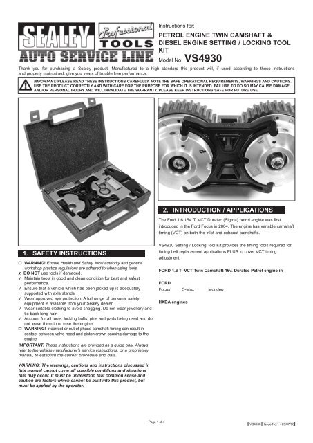
<strong>Petrol</strong> <strong>engine</strong> <strong>twin</strong> <strong>Camshaft</strong> &<br />
<strong>Diesel</strong> <strong>engine</strong> setting / loCking tool<br />
kit<br />
Model No: Vs4930<br />
Thank you for purchasing a Sealey product. Manufactured to a high standard this product will, if used according to these instructions<br />
and properly maintained, give you years of trouble free performance.<br />
IMPORTANT: Please reaD these instrUCtions CarefUllY. note the safe oPerational reQUirements, warnings anD CaUtions.<br />
Use the ProDUCt CorreCtlY anD with Care for the PUrPose for whiCh it is intenDeD. failUre to Do so maY CaUse Damage<br />
anD/or Personal inJUrY anD will inValiDate the warrantY. Please keeP instrUCtions safe for fUtUre Use.<br />
1. safetY instrUCtions<br />
warning! Ensure Health and Safety, local authority and general<br />
workshop practice regulations are adhered to when using tools.<br />
Do not use tools if damaged.<br />
Maintain tools in good and clean condition for best and safest<br />
performance.<br />
Ensure that a vehicle which has been jacked up is adequately<br />
supported with axle stands.<br />
Wear approved eye protection. A full range of personal safety<br />
equipment is available from your Sealey dealer.<br />
Wear suitable clothing to avoid snagging. Do not wear jewellery and<br />
tie back long hair.<br />
Account for all tools, locking bolts, pins and parts being used and do<br />
not leave them in or near the <strong>engine</strong>.<br />
warning! Incorrect or out of phase camshaft timing can result in<br />
contact between valve head and piston crown causing damage to the<br />
<strong>engine</strong>.<br />
IMPORTANT: These instructions are provided as a guide only. Always<br />
refer to the vehicle manufacturer’s service instructions, or a proprietary<br />
manual, to establish the current procedure and data.<br />
WARNING: The warnings, cautions and instructions discussed in<br />
this manual cannot cover all possible conditions and situations<br />
that may occur. It must be understood that <strong>com</strong>mon sense and<br />
caution are factors which cannot be built into this product, but<br />
must be applied by the operator.<br />
2. introDUCtion / aPPliCations<br />
The Ford 1.6 16v. Ti VCT Duratec (Sigma) petrol <strong>engine</strong> was first<br />
introduced in the Ford Focus in 2004. The <strong>engine</strong> has variable camshaft<br />
timing (VCT) on both the inlet and exhaust camshafts.<br />
VS4930 Setting / Locking Tool Kit provides the timing tools required for<br />
timing belt replacement applications PLUS to cover VCT timing<br />
adjustment.<br />
forD 1.6 ti-VCt <strong>twin</strong> <strong>Camshaft</strong> 16v. Duratec <strong>Petrol</strong> <strong>engine</strong> in<br />
forD<br />
Focus C-Max Mondeo<br />
hXDa <strong>engine</strong>s<br />
VS4930 Issue No:1 - 23/07/08
3. Contents<br />
1 . ....VS3032/21. ...Crankshaft TDC Location Pin<br />
2 . . . . . VS4640/T7. ...Tensioner Locking Pin<br />
3 . . . . . VS4931 ......VCT Setting Plate<br />
4 . . . . . VS4832 ......Flywheel Locking Tool<br />
5 . . . . . VS4933 . .....<strong>Camshaft</strong> Setting Plate<br />
- .....VS4930/84. ...Case + Insert<br />
Fig.1<br />
4. instrUCtions<br />
The Ford 1.6 16v. Ti VCT Duratec (Sigma) petrol <strong>engine</strong> was first<br />
introduced in the Ford Focus in 2004. The <strong>engine</strong> has variable camshaft<br />
timing (VCT) on both the inlet and exhaust camshafts. (Fig.1).<br />
4.1 timing Belt replacement<br />
Raise and support the front of the vehicle in order to remove the<br />
Right-Hand front road wheel.<br />
Remove the air filter housing/assembly, PAS reservoir<br />
(do not disconnect) and auxiliary belt.<br />
Remove alternator and starter motor. Detach the coolant expansion tank<br />
(do not disconnect), and position to one side.<br />
Remove the coolant pump pulley and upper timing belt cover.<br />
Turn the crankshaft until the timing marks on the VCT Units are in the<br />
11-o-clock position (crankshaft is just before TDC No.1 cylinder).<br />
note: The crankshaft must only be turned in the direction of normal<br />
rotation.<br />
Page 2 of 4<br />
Fig.2<br />
4.1.1 Vs3032/21 Crankshaft tDC location Pin<br />
Remove the blanking plug in the <strong>engine</strong> block, in order to insert the<br />
VS3032/21 Crankshaft Location Pin.<br />
Carefully and slowly, turn the crankshaft clockwise to rest fully on the<br />
VS3032/21 Location Pin. (Fig.2).<br />
Fig.3<br />
4.1.2 Vs4832 flywheel locking tool<br />
Ensure the crankshaft is fully resting on the VS3032/21 Location Pin<br />
and ‘lock’ the flywheel by installing VS4832 Flywheel Locking Tool at the<br />
starter motor position. (Fig.3).<br />
The camshaft timing marks should be at 12-o-clock position. The marks<br />
are located on front of the sprocket teeth – “I” on the Left-Hand sprocket<br />
and “•” on the Right-Hand sprocket.<br />
Remove the crankshaft pulley and discard its centre bolt. Remove the<br />
lower belt cover.<br />
Support the <strong>engine</strong> and remove the front <strong>engine</strong> mounting bracket after<br />
marking its installed position.<br />
VS4930 Issue No:1 - 23/07/08
4.1.3 Vs4931 VCt setting Plate<br />
Fit VS4931 VCT Setting Plate onto the VCT Units. The word “toP”<br />
should be visible on top of the Setting Plate. The “Scribe Mark I “ should<br />
be on the Left-Hand arm of the Setting Plate, with the “Zero (Dot) Mark 0”<br />
on the Right-Hand arm of the Plate, matching the timing marks on the<br />
camshaft sprockets. (fig.4).<br />
Fig.5<br />
Fig.4<br />
4.1.4 Vs4640/t7 tensioner locking Pin<br />
Apply pressure to the timing belt to activate the tensioner pulley and<br />
allow the insertion of Locking Pin VS4640/T7. (Fig. 5).<br />
Remove the old timing belt and discard.<br />
4.2 installing new belt<br />
Check that the VCT Setting Plate, Crankshaft Location Pin and Flywheel<br />
Locking Tool are correctly fitted.<br />
Install the new timing belt in a clockwise direction, starting at the VCT<br />
Units/camshaft sprocket, then the crankshaft gear. Ensure the belt is taut<br />
between sprockets.<br />
4.2.1 Once the belt is fully fitted, remove the VS4640/T7 Tensioner<br />
Locking Pin to release tension on to the belt.<br />
4.2.2 Measure the depth of the bore in the crankshaft to determine the<br />
correct new crankshaft pulley centre bolt to use.<br />
If bore depth is 42mm. – use M12 x 29mm bolt<br />
If bore depth is 52mm. – use M12 x 44.5mm bolt.<br />
Install the lower belt cover.<br />
Page 3 of 4<br />
Fig.6<br />
4.2.3 Install the crankshaft pulley, counter-hold pulley with a suitable<br />
Holding Tool whilst tightening the centre bolt, in two stages, 45Nm. + 90<br />
degrees. (Fig.6).<br />
note: Crankshaft gear does not have a keyway<br />
4.2.4 Remove the VCT Setting Plate, Crankshaft Location Pin and<br />
Flywheel Locking Tool.<br />
4.2.5 Turn the crankshaft carefully, by hand, 2 turns in the direction of<br />
normal rotation and return to the position where the marks on the VCT<br />
Units are at 11- o‘clock.<br />
4.2.6 Insert VS3032/21 Crankshaft Location Pin and carefully turn the<br />
crankshaft to rest fully on the Location Pin.<br />
Fig.7a<br />
Fig.7b<br />
4.2.7 Fit VS4931 VCT Setting Plate on to the VCT Units and check that<br />
the timing marks on the VCt Units and camshaft sprockets align and<br />
are near to the outer edges of the Setting Plate upper arms. (Fig.7).<br />
If the timing marks do not align, repeat the belt installation and tensioning<br />
procedures.<br />
VS4930 Issue No:1 - 23/07/08
4.3 timing adjustment - setting the VCt Units<br />
(Cylinder head/<strong>Camshaft</strong> replacement applications)<br />
When carrying out work on cylinder head / camshaft replacement or<br />
valve timing adjustment it will be necessary to re-set the VCT /<br />
camshafts.<br />
When removing the VCT Units, counter-hold the camshafts, with a<br />
spanner, at the hexagons provided on the camshafts. Remove the centre<br />
blanking plugs of the VCT Units, and unscrew and remove the centre<br />
retaining bolts.<br />
Fig.8<br />
4.3.1 Vs4933 <strong>Camshaft</strong> setting Plate<br />
When installing the VCT Units, the crankshaft is positioned at TDC No.1<br />
cylinder and VS4933 <strong>Camshaft</strong> Setting Plate is inserted into the slots<br />
located at the rear of the camshafts to position the camshafts in their<br />
‘timed’ position. (Fig.8).<br />
4.3.2 The VCT Units are placed onto the camshafts and the new centre<br />
retaining bolts are inserted and screwed to finger-tight only.<br />
4.3.3 The timing mark of each of the VCT Units should be positioned at<br />
the 12-o-clock position.<br />
VS4931 Setting Plate is inserted onto the VCT Units and the centre bolts<br />
tightened to 25Nm.<br />
4.3.4 Remove VS4931 and VS4933 Setting Plates.<br />
4.3.5 Counter-hold the camshafts, with a spanner, at the hexagons<br />
provided on the camshafts and carry out the final tightening procedure –<br />
tightening the VCT centre retaining bolts 75 degrees.<br />
warning: Do not use Vs4931 and Vs4933 setting Plates to<br />
counter-hold camshafts/VCT Units during final tightening procedure<br />
of the VCt Units retaining bolts.<br />
4.3.6 Insert VS4931 Setting Plate to check that the timing position is<br />
correct and that the timing marks on the sprockets align with the marks<br />
on the VCT Units near to the outer edges of VS4931 Setting Plate upper<br />
arms.<br />
NOTE: It is our policy to continually improve products and as such we reserve the right to alter data, specifications and <strong>com</strong>ponent parts without prior notice.<br />
imPortant: No liability is accepted for incorrect use of this product.<br />
warrantY: Guarantee is 12 months from purchase date, proof of which will be required for any claim.<br />
information: For a copy of our latest catalogue and promotions call us on 01284 757525 and leave your full name and address, including postcode.<br />
sole Uk Distributor<br />
sealey group,<br />
Bury St. Edmunds, Suffolk.<br />
01284 757500<br />
www.sealey.co.uk<br />
01284 703534 email sales@sealey.co.uk<br />
Page 4 of 4 VS4930 Issue No:1 - 23/07/08<br />
Web


