Network Transformers - Augier
Network Transformers - Augier
Network Transformers - Augier

You also want an ePaper? Increase the reach of your titles
YUMPU automatically turns print PDFs into web optimized ePapers that Google loves.
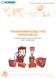
TRANSFORMERS TYPE TED<br />
<strong>Network</strong> <strong>Transformers</strong><br />
(0.4 to 160 kVA)<br />
PRODUCT LEAFLET<br />
1<br />
60 10602 - 09/06/2011
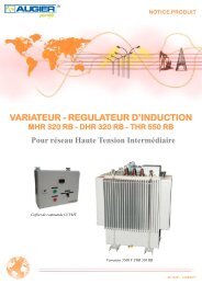
PRODUCTS PRESENTATION<br />
SINGLE PHASE TRANSFORMERS FOR SINGLE PHASE NETWORKS<br />
Concentric two-pole cable<br />
TED MMX<br />
400 and 630 VA<br />
TED MMX<br />
1 to 5 kVA<br />
TED MMX<br />
10 kVA<br />
NETWORK ACCESSORIES<br />
Two-pole boxes :<br />
Dead end box 1 A<br />
Junction 1 A / 1 D<br />
Derivation 1 A / 2 D<br />
Derivation 1 A / 3 D<br />
TED MMX<br />
16 to 50 kVA<br />
SINGLE-PHASE TRANSFORMERS FOR THREE-PHASE NETWORKS<br />
Single pole or three pole cables<br />
TED MTT<br />
2 to 10 kVA<br />
TED MTT<br />
16 to 50 kVA<br />
<strong>Network</strong> accessories<br />
three pole box 1 A / 1 D<br />
THREE PHASE TRANSFORMERS FOR THREE PHASE NETWORKS<br />
Single-pole or three-pole cables<br />
TED TTT 5 to 32 kVA<br />
TEH TTT 50 to 160 kVA<br />
2
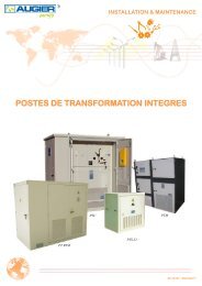
NETWORK TRANSFORMERS<br />
Type TED 0.4 to 160 kVA<br />
« Lead through » connection<br />
CONTENTS<br />
Pages<br />
GENERAL PRESENTATION ............................................................................................4 - 5<br />
SINGLE-PHASE NETWORKS<br />
- Single-phase transformers for single-phase networks<br />
* TED MMX from 0,4 to 10 kVA.......................................................................6 - 7<br />
* TED MMX from 16 to 50 kVA........................................................................8 - 9<br />
- Accessories for a single-phase network.....................................................................10 - 11<br />
- Two-pole terminal - model X.....................................................................................12 - 13<br />
THREE-PHASE NETWORKS<br />
- Single-phase transformers for three-phase networks<br />
* TED MTT from 2 to 10 kVA.........................................................…………..14 - 15<br />
* TED MTT from 16 to 50 kVA.........................................................................16 - 17<br />
- Three-phase transformers for three-phase networks<br />
* TED TTT from 5 to 32 kVA............................................................………….18 - 19<br />
* TEH TTT from 50 to 160 kVA.........................................................................20 - 21<br />
- Three-pole terminal.....................................................................................................22 - 24<br />
- Accessories for three-phase networks………………………………………………..25<br />
INTERLOCKING...................................................................................................................26<br />
BLUE BIP...............................................................................................................................27<br />
3
ALL THE AVANTAGES OF EPOXY RESINS<br />
For single-phase (400 VA to 50 kVA)<br />
or three-phase (5 kVA to 32 kVA) unpluggable transformers<br />
The use of epoxy resin guarantees that the transformers have the following characteristics:<br />
Corrosion resistant, remain unaltered over time.<br />
Watertight and immersible.<br />
Insulated.<br />
Can be buried into purposely-designed pits.<br />
MODULOBLOCS: MAIN CHARACTERISTICS<br />
Watertight and immersible sets.<br />
Conform to NFC 52 410 standards.<br />
Dielectric : Oil<br />
Primary insulation voltage : 7.2 kV<br />
Secondary insulation voltage : 1.1 kV<br />
Reduced losses<br />
Protection degree : IP 68 - IK 10<br />
Working temperature : - 15°C + 40°C<br />
Specially designed to support the no load lamp stress & strain.<br />
Studied to allow to allow network continuity in case of a transformer fault.<br />
MV PLUG-IN CONNECTION:<br />
The MV plug-in terminal systems of the connection interface guarantee total operational flexibility:<br />
Easy to plug in and unplug<br />
Optimum reliability: reinfored by isolating liquid BIP in the terminal compartments regardless of type of cable<br />
used, <strong>Augier</strong>’s specially-designed plug-in terminal meets all your needs.<br />
A switch protection channel inside the transformer allows insulation of a section by simply plugging in.<br />
TED MMX<br />
Two-pole terminal<br />
For concentric<br />
Two-pole cables<br />
TED MTT<br />
Elbow bent<br />
three-pole terminal<br />
for twisted cables<br />
The transformer low voltage output is carried out with a 1.5 metre-long H 07 RNF cable or on pluggable terminals.<br />
4
DOUBLE «AUTO» PROTECTED TRANSFORMERS:<br />
The protection devices directly incorporated in the transformer guarantee :<br />
MV protection by easily accessible HRC fuses.<br />
Optional:<br />
Low Voltage protection by means of thero-magnetic circuit breakers allows protection against short circuiting,<br />
linked to thermal protection with of a probe incorperated in the windings which guarantees elimination of<br />
possible permanent faults.<br />
Protection by HRC fuses.<br />
Stick fuse on a<br />
TED MMX 5 kVA<br />
TED TRANSFORMERS: ADVANTAGES<br />
Stick fuse on a<br />
TED TTT 5 kVA<br />
Complete range of equipment, to enable absence of voltage tests (VAT) to be<br />
carried out to conform to recommended NFC 17-200 standards, available on<br />
request.<br />
Connection accessories are routinely delivered with each transformer.<br />
Voltage adjusting tap changers of + 5 and + 7.5 % are provided to transformers<br />
from 16 kVA and to the three- phase transformers of all power ratings.<br />
A phase selector allows an even load distribution among the 3 phases of the<br />
supply network.<br />
Four-pole circuit breaker<br />
on a TED TTT 10 kVA<br />
Plug-in, MV network epoxy resin accessories are also available. They enable cable isolation to be carried out,<br />
among other things.<br />
On request <strong>Augier</strong> technicians carry out on site technical<br />
assistance, in France and world wide. This assistance<br />
facilitates start up of the MV installations and guarantees<br />
tecnical training leading to full understanding of the<br />
technical features of the product and how it works.<br />
5
TYPE<br />
Single-phase transformer for single-phase networks.<br />
Cast in resin, corrosion resistant, water-tight, plug-in<br />
connection designed for directly buried installation.<br />
Protection degree : IP 68<br />
Primary voltage : 3200 V (1)<br />
Primary winding insulation level : 7,2 kV<br />
Secondary no-load voltage : 237 V (2)<br />
Secondary winding insulation level : 1,1 kV<br />
Coupling : single-phase<br />
Dielectric : oil<br />
Power rating : 400, 630, 1000, 2000, 3000,<br />
5000, 10000 VA<br />
Nominal power depending on public lighting standards<br />
320, 504, 800, 1600, 2400, 4000, 8000 VA<br />
<strong>Transformers</strong> comply with NFC 52 410 standards.<br />
CONDITIONS of USE:<br />
Environmental class AD7 : can be partly or completely<br />
immersed in water for a limited time period.<br />
MV INLET<br />
A -Two -pole plug-in concentric, universal terminals for<br />
3.6/6 kV concentric two -pole cable 2 x 6, 10, 16, or<br />
25 mm² cross-section conforming to NF C33-221 standards.<br />
B - «Lead-through» connection in transformer.<br />
TAP CHANGER FOR VOLTAGE ADJUSTMENT<br />
No adjustment.<br />
MV PROTECTION<br />
By means of HRC fuse, rupturing capacity 15 kVA.<br />
MV POTENTIAL CONDITION<br />
The winding is not connected to earth potential.<br />
On request: Earthed end of the winding connected to<br />
outer conductor (neutral) of the cable.<br />
(1) On request: other voltages compatible with primary winding<br />
insulation level.<br />
(2) On request: other voltages compatible with secondary<br />
winding insulation level.<br />
TED MMX - 0.4 to 10 kVA<br />
LV OUTLET<br />
Two-pole 6 metre-long H.07.RN.F cable<br />
< to 1 kVA : cross-section 2 x 2.5 mm²<br />
1 to 5 kVA : cross-section 2 x 6 mm²<br />
10 kVA : cross-section 2 x 10 mm²<br />
On request : two-pole plug-in terminal for H.07.RN.F.<br />
cable with maximum 2 x 25 mm² cross-section.<br />
LV PROTECTION<br />
Without LV protection<br />
On request:<br />
The cut-out device ensures direct magnetic protection<br />
and thermal protection by means of a probe incorporated<br />
in the windings; breaking capacity: 6 kA.<br />
*Single-pole + neutral, curve B, for the TED ≤ 6 kVA<br />
*Two-pole, curve B, for the TED > 6 kVA<br />
By HRC fuses.<br />
LV POTENTIAL CONDITION<br />
One end of the LV winding is connected to the earthing terminal<br />
(blue lead).<br />
On request: centre tap of the LV winding connected to the<br />
earthing terminal. In this case, possible LV protection must<br />
be two-pole.<br />
EARTHING TERMINAL<br />
By means of a M10 threaded rod, connected internally to<br />
magnetic circuit.<br />
DIELECTRIC TESTS<br />
Impulse withstands : 45 kV - Wave 1 / 50<br />
Power frequency withstands voltage : 16 kV - 50 Hz -<br />
1 minute.<br />
USER INFORMATION WRITTEN ON COVER<br />
Terminals assembly instructions:<br />
manuals available on request.<br />
EQUIPMENTS<br />
The transformers are delivered with :<br />
Two HV preparation leaflets.<br />
Two non-waterproof transport plugs.<br />
The BIP is delivered separately.<br />
Handling ropes.<br />
Technical leaflet for the assembly of the plug-in<br />
terminals.<br />
6
TED MMX 400, 630 VA<br />
TED MMX 10 kVA<br />
TED MMX 1 to 5 kVA<br />
TED MMX TECHNICAL DATA - 0.4 to 10 kVA<br />
1 - MV fuses<br />
2 - MV Input terminal<br />
3 - Output terminal<br />
4 - Rating plate<br />
5 - Earth terminal<br />
6 - LV protection (optional)<br />
7 - Two-pole LV output<br />
Power rating (kVA) 400 630 1000 2000 3000 5000 10000<br />
Power output (kVA) 320 504 800 1600 2400 4000 8000<br />
Iron losses (W) 10 15 20 30 45 60 110<br />
Copper losses (W) 13 20 26 38 45 75 130<br />
Short-circuit impedance (%) 3.4 3.4 2.9 2.5 2.5 2.5 3.0<br />
Voltage drop (%) cos φ = 1 3.2 3.17 2.6 1.91 1.52 1.52 1.34<br />
Voltage drop (%) cos φ = 0,8 3.16 3.28 2.84 2.49 2.4 2.4 2.66<br />
Magnetising current (%) 12 10 9 8.5 8 8 5<br />
Length (mm) 361 361 400 400 400 400 Ø500<br />
Width (mm) 256 256 374 374 374 374 Ø500<br />
Height (mm) 430 430 435 435 435 435 565<br />
Total weight (kg) 33 35 55 60 65 77 145<br />
Weight of oil filling (kg) 4 3.6 8 7.6 8 7.6 18.5<br />
7
TYPE<br />
Single-phase transformer for single-phase networks.<br />
Cast in resin, corrosion resistant, water-tight, plug-in<br />
connection designed for directly buried installation.<br />
Protection degree : IP 68<br />
Primary voltage : 3200 V (1)<br />
Primary winding insulation level : 7.2 kV<br />
Secondary no-load voltage : 237 V (2)<br />
Secondary winding insulation level : 1.1 kV<br />
Coupling : single phase<br />
Dielectric : oil<br />
Power rating : 16 - 25 - 32 - 50 kVA<br />
Nominal power depending on public lighting standards<br />
12.8 - 20 - 25.6 - 40 kVA<br />
<strong>Transformers</strong> comply with NFC 52 410 standards.<br />
OPERATING CONDITIONS<br />
Environmental condition AD7 : can be partly or<br />
completely immersed in water for a limited time period.<br />
MV INLET<br />
A- Two-pole plug-in concentric, universal terminals for<br />
3.6/6 kV concentric two-pole cable 2 x 6, 10, 16, or<br />
25 mm² cross-section according to NF C33-221 standards.<br />
B- «Lead-through» connection in transformer.<br />
TAP CHANGER FOR VOLTAGE ADJUSTMENT<br />
Adjustment by strips off voltage, taps + 5, + 7.5 % (3)<br />
MV PROTECTION<br />
By means of HRC fuse, rupturing capacity 50 kA.<br />
MV POTENTIAL CONDITION<br />
The winding is not connected to earth potential.<br />
On request: Earthed end of the windin connected to the<br />
outer conductor (neutral) of the cable.<br />
(1) On request: other voltages compatible with primary winding<br />
insulation level.<br />
(2) On request: other voltages compatible with secondary<br />
winding insulation level.<br />
(3) Other percentage values on request.<br />
TED MMX - 16, 25, 32, 50 kVA<br />
LV OUTLET<br />
Two-pole 6 metre-long H.07.RN.F cable , cross-section:<br />
16 kVA: 25 mm² for 230 V. Two single-pole 6 metre-long<br />
H.07.RNF cable, cross-section:<br />
25 kVA: 35 mm² for 230 V.<br />
32 kVA : 50 mm² for 230 V<br />
50 kVA : 95 mm² for 230 V.<br />
On request for the 16 kVA : two-pole plug-in<br />
terminal for H.07.RN.F. cable with a maximum<br />
cross-section of 2 x 25 mm².<br />
LV PROTECTION<br />
Without LV protection<br />
On request:<br />
The cut-out device ensures magnetic protection and<br />
thermal protection by means a probe incorporated in<br />
the winding (only for the 16 and 25 kVA)<br />
Breaking capacity: 16 kVA : 85 kA - 25 kVA : 85 kA<br />
Protection by means of one HRC fuse<br />
LV POTENTIAL CONDITION<br />
One end of the LV winding is connected to the earthing<br />
terminal (blue lead).<br />
On request: centre tap of the LV winding connected to<br />
the earthing terminal.<br />
EARTHING TERMINAL<br />
By means of a M10 threaded rod, connected internally to<br />
the transformer core.<br />
DIELECTRIC TESTS<br />
Impulse withstands: 45 kV - wave 1/ 50<br />
Power frequency withstands voltage:<br />
16 kV - 50 Hz - 1 minute<br />
USER INFORMATION WRITTEN ON<br />
THE COVER<br />
Terminals assembly instructions:<br />
Manual available on request.<br />
EQUIPMENTS<br />
The transformers are delivered with:<br />
Two MV plug-in terminals for assembly.<br />
Two non-waterproof blanking off taps.<br />
The BIP is delivered separately.<br />
Handling ropes.<br />
One technical leaflet for the assembly of the MV<br />
plug-in terminals.<br />
8
TED MMX 16 kVA TED MMX 25 kVA<br />
Input Output<br />
TED MMX 32 - 50 kVA<br />
Input Output<br />
Input Output<br />
1 - LV Protection (optional)<br />
2 - LV Output<br />
3 - MV adjustment switch<br />
4 - Two-pole unpluggable terminals<br />
5 - MV fuses<br />
TED MMX TECHNICAL DATA - 16, 25, 32, 50 kVA<br />
Power rating (kVA) 16 25 32 50<br />
Power output (kVA) 12.8 20 25.6 40<br />
Iron losses (W) 100 130 155 160<br />
Copper losses (W) 360 580 600 900<br />
Short-circuit impedance (%) 5.5 5 5 6.5<br />
Voltage drop (%) cos φ = 1 2.3 2.42 1.98 2.00<br />
Voltage drop (%) cos φ = 0,8 4.81 4.51 4.28 5.11<br />
Magnetising current (%) 6 5 3.1 2.3<br />
Length (mm) 658 784 925 925<br />
Width (mm) 540 574 652 650<br />
Height (mm) 620 720 830 830<br />
Total weight (kg) 250 375 530 650<br />
Weight of oil filling (kg) 35 75 100 110<br />
9
ACCESSORIES FOR SINGLE-PHASE NETWORKS<br />
DEAD END BOX, JUNCTION AND<br />
DEVIATION BOXES<br />
These different boxes made up of pluggable universal<br />
two-pole consentric terminals receive either a concentric<br />
two-pole 3.6 / 6 kV cable, or a radical field single pole<br />
3.6 / 6 kV cable made up of a twisted cable strut. A single<br />
pole cable’s cross section can be either 6, 10, 16, 25 or 35<br />
mm². External diameter of the watertight outer covering<br />
can’t exceed 24 mm.<br />
They are delivered with the necessary equipment needed<br />
to make the MV cable heads, as well as thewaterproof<br />
plug covers.<br />
1AX Box<br />
(dead end box)<br />
1AX / 1DX Box<br />
(junction box)<br />
JUNCTION AND DEVIATION BOXES WITH<br />
EARTHING OF THE PERIPHERAL CABLE<br />
On all these boxes it is possible to add an earthing<br />
terminal connected to the interior of the plug-in<br />
peripheral terminals. This addition does not change<br />
its dimensions.<br />
1AX / 2DX Box<br />
(T-deviation box)<br />
1AX / 3DX Box<br />
(Cross-type deviation box)<br />
Length Width Height Weight<br />
1AX 70 70 375 1.5 kg<br />
1AX / 1DX 150 70 375 3.3 kg<br />
1AX / 2DX 150 150 375 5.6 kg<br />
1AX / 3DX 150 150 375 7.4 kg<br />
10
LINE DEAD END SPARKS GAP<br />
<strong>Network</strong> in TNRS* diagram with a concentric two-pole cable<br />
The peripheral conductors (neutral) of the concentric two pole 3.5/6 kV cable are insulated to 1000 V level. In the<br />
event of using this cable with a TNRS distribution system, accidental damage to cable will result in a short circuit<br />
with the central conductor (3.5/6 kV); causing peripheral voltage to exceed the 1000 V limit to 3200 V. This can<br />
also be caused by the primary winding of the TED transformer.<br />
A line dead end spark gap results in a connection between the peripheral cable and the earth. An overvoltage limiter<br />
allows, in this case, a dangerous potential to pass the cable.<br />
This will activate the differential protection installed in the delivered substations public lighting switchboards, on<br />
the feeder concerned.<br />
The transformer is delivered with a 2 m strap of 25 mm² concentric two-pole cable equipped with a universal cable<br />
head, to be plugged into the terminal left unused of the last TED transformer of the line or of the deviation.<br />
It is imperative that the earth terminal be connected to the small earth cable.<br />
Brochures available on request.<br />
FRONT VIEW TOP VIEW<br />
MV NETWORK MAINTENANCE ACCESSORIES<br />
These accessories enable operations to be carried out following recommended safety rules, in particular to test for<br />
absence of voltage before intervention of TED transformer.<br />
* TNRS diagram applies to cases where the cable periphiral conductor is maintained isolated at level of network transformers.<br />
11
GENERAL INFORMATION<br />
TWO-POLE TERMINAL MODEL X<br />
This terminal consists of two parts :<br />
a- the plug is joined to the device and contains a central and periphical contact. It is designed to receive all plugs<br />
from 6 to 25mm².<br />
b- the plug is on the cable. The parts ensuring electric contacts must be adapted to cable cross-section.<br />
PROTECTION AGAINST WATER PENETRATION<br />
This is carried out in two stages :<br />
Between the sheath (3) and the envelope with the help of an o-ring seal (4). Toughness: 70° shore, +/- 5°.<br />
Between the cable and the sheath (3) with the help of a thermo-retractable sheath.<br />
NB: extra insulation is provided using an insulating liquid BIP inside the terminal compartment. This liquid acts as<br />
a density dielectric, thus allowing water to be kept on surface; otherwise this would get inside the terminal in the<br />
event of cable damage.<br />
IMPORTANT<br />
Essential infomation to be given on order:<br />
• Type and section of cable.<br />
• Provide sample of cable if it’s a special type.<br />
Example of protected cable<br />
Copper core<br />
Semi-conductor<br />
PR insulation<br />
Waterproof concentric<br />
conductor<br />
Redinsulation shaft<br />
Cable protection<br />
Redexterior shaft<br />
Cable cross<br />
section<br />
(mm²)<br />
RECOMMENDED CABLE<br />
Two-pole concentric cable 3,6 / 6 kV<br />
Maximum<br />
diameter on<br />
the insulation<br />
(mm)<br />
Approximate diameter<br />
on the exterior sleeve (mm)<br />
Non<br />
protected cable<br />
Acceptable<br />
current (A)<br />
Protected cable Buried<br />
6 + 6 16 18.6 19.6 63<br />
10 + 10 16.5 19.2 20.2 90<br />
16 + 16 18.3 21 22 115<br />
25 + 25 20.5 23.2 24.2 150<br />
Curved ribbon : 10 x diameter<br />
12
2<br />
1<br />
3<br />
4<br />
Accessories for the two-pole plug<br />
5<br />
6<br />
8<br />
7<br />
9<br />
Mounted<br />
two-pole plug<br />
Socket on the top<br />
of the TED MMX<br />
1- Screwing nut<br />
2- Thermo-retractable sleeve<br />
3- Sheath<br />
4- O-ring seal<br />
5- Peripheral nozzle<br />
6- Under the peripheral nozzle<br />
7- Central nozzle<br />
8- Spacer<br />
9- Nut<br />
Plugged-in and then<br />
waterproofed two-pole plug<br />
13
TYPE<br />
Single-phase transformer for three -phase networks. Cast<br />
in resin, corrosion resistant, water-tight, plug-in<br />
connection designed for directly buried installation.<br />
Protection degree : IP 68<br />
Primary voltage : 5500 V (1)<br />
Primary winding insulation level : 7.2 kV<br />
Secondary no-load voltage : 237 V (2)<br />
Secondary winding insulation level : 1.1 kV<br />
Coupling : single-phase<br />
Dielectric : oil<br />
Power rating : 2 - 3 - 5 - 10 kVA<br />
Nominal power depending on public lighting<br />
standards : 1.6 - 2.4 - 4 - 8 kVA<br />
<strong>Transformers</strong> comply with NFC 52410 standards.<br />
OPERATING CONDITIONS<br />
Environmental condition AD7: can be partly or completely<br />
immersed in water, for a limited time period.<br />
MV INLET<br />
a- Three-phase plug-in connection for three-phase cable,<br />
6 kV, belt or radial field type (see description 60 10472)<br />
Maximum current: 80 A<br />
Maximum overall diameter of cable: 44,5 mm, maximum<br />
allowance included.<br />
b- «Lead-through» connection in transformer.<br />
TAP CHANGER FOR VOLTAGE ADJUSTMENT<br />
No voltage adjustment provided.<br />
MV PROTECTION<br />
By means of two HRC fuses, rupturing capacity 10 kA.<br />
PHASE SELECTOR<br />
Medium Voltage fuses allows even load distribution<br />
among the three- phases of supply network.<br />
(1) On request : other voltages compatible to the primary<br />
winding insulation level.<br />
(2) On request : other voltages compatible to the secondary<br />
winding insulation level.<br />
TED MTT - 2, 3, 5, 10 kVA<br />
LV OUTLET<br />
Two-pole 6 m. H.07 cable :<br />
2 to 5 kVA: cross-section 6 mm²<br />
10 kVA: cross-section 10 mm²<br />
On request: Two-pole plug-in terminal for H.07.RN.F<br />
cable with maximum cross-section 25 mm².<br />
LV PROTECTION<br />
Without Low Voltage protection<br />
On request:<br />
The cut-out device ensures direct magnetic and thermal<br />
protection by means of a probe incorporated in the<br />
windings, breaking capacity: 6 kA<br />
*single-pole + neutral, curve B, for TED ≤ 6 kVA:<br />
*two-pole, curve B for TED > 6 kVA<br />
By HRC fuses.<br />
LV ELECTRICAL POSITION<br />
The end of the LV winding is linked to earthing terminal<br />
(blue conductor).<br />
On request: Centre tap of LV winding connected to the<br />
earthing terminal. In this case, possible LV protection<br />
must be two-pole.<br />
EARTHING TERMINAL<br />
By means of a M10 threaded rod, connected internally to<br />
magnetic circuit.<br />
DIELECTRIC TESTS<br />
Impulse withstand: 60 kV - Wave shape 1 / 50<br />
Power frequency<br />
withstand voltage: 22 kV - 50 Hz -1 minute<br />
USER INFORMATION WRITTEN ON COVER<br />
MV cable terminal assembly instructions : manual<br />
available on request for different cable types.<br />
EQUIPMENTS<br />
<strong>Transformers</strong> are delivered with:<br />
Two MV plug-in terminals for assembly.<br />
Two non-waterproof transport only taps.<br />
BIP delivered separately.<br />
Handling ropes.<br />
One technical leaflet for assembling MV plug-in<br />
terminals.<br />
14
TED MTT 2 to 10 kVA<br />
1- MV fuses and phase-selector<br />
2- MV three-pole terminal<br />
3- MV inlet<br />
4- MV outlet<br />
5- Rating plate<br />
6- Earthing terminal M 10 x 20<br />
7- LV protection (optional)<br />
8- LV output<br />
TED MTT TECHNICAL DATA - 2, 3, 5, 10 kVA<br />
Power rating (kVA) 2 3 5 10<br />
Power output (kVA) 1.6 2.4 4 8<br />
Iron losses (W) 30 45 60 110<br />
Copper losses (W) 38 45 75 130<br />
Short-circuit impedance (%) 2.5 2.5 2.5 3<br />
Voltage drop (%) cos φ = 1 1.91 1.52 1.52 1.34<br />
Voltage drop (%) cos φ = 0,8 2.49 2.4 2.4 2.66<br />
Magnetising current (%) 8.5 8 8 5<br />
Diameter (mm) Ø500 Ø500 Ø500 Ø500<br />
Height (mm) 485 485 485 485<br />
Total weight (kg) 100 110 115 170<br />
Weight of oil filling (kg) 20 18 14 23<br />
15
TED MTT - 16, 25, 32, 50 kVA<br />
TYPE<br />
Single-phase transformer for three-phase networks. Cast in<br />
resin, corrosion resistant, water-tight, plug-in<br />
connection designed for directly buried installation.<br />
Protection degree : IP 68<br />
Primary voltage : 5500 V (1)<br />
Primary winding insulation level : 7.2 kV<br />
Secondary no-load voltage : 237 V (2)<br />
Secondary winding insulation level : 1.1 kV<br />
Coupling : single phase<br />
Delectric : oil<br />
Power rating : 16 - 25 - 32 - 50 kVA<br />
Nominal power depending on public<br />
lighting standards : 12.8 - 20 - 25.6 - 40 kVA<br />
<strong>Transformers</strong> comply with NFC 52410 standards.<br />
OPERATING CONDITIONS<br />
Environmental condition AD7: can be partly or completely<br />
immersed in water for a limited time period.<br />
MV INLET<br />
a- Three-phase plug-in connection for three-phase cable, 6<br />
kV, belt or radial field type (see leaflet 60 10472)<br />
Maximum current : 80 A<br />
Maximum overall cable diametre : 44.5 mm, maximum<br />
allowance included.<br />
On request : elbow bent terminals.<br />
b- «Lead-through» connection in transformer.<br />
TAP CHANGER FOR VOLTAGE ADJUSTMENT<br />
Adjustment by strips off voltage, taps + 5, + 7,5 % (3)<br />
MV PROTECTION<br />
By means of two HRC fuses, rupturing capacity 15 kA.<br />
PHASE SELECTOR<br />
By means of a switching device, allowing even load<br />
distribution among the three phases of supply network.<br />
(1) On request : other voltages compatible with primary winding<br />
insulation level.<br />
(2) On request : other voltages compatible with secondary<br />
winding insulation level.<br />
(3) Other percentage values on request.<br />
LV OUTLET<br />
Two-pole 6 meter-long H.07.RN.F cable<br />
16 kVA : cross-section 25 mm²<br />
Two single-pole 6 meter-long H.07.RN.F cable<br />
25 kVA : cross-section 50 mm²<br />
32 kVA : cross-section 50 mm²<br />
50 kVA : cross-section 95 mm²<br />
On request for the 16 kVA : two-pole plug-in terminal<br />
for H.07.RN.F cable with 25 mm² maximum cross-section.<br />
LV PROTECTION<br />
Without low voltage protection. On request, the cut-out<br />
device ensures direct magnetic protection and thermal<br />
protection by means of a probe incorporated in the<br />
windings (only for the 16 and 25 kVA).<br />
Breaking capacity : 16 kVA : 85 kA - 25 kVA : 85 kA<br />
Protection by HRC fuses.<br />
LV POTENTIAL CONDITION<br />
One end of the LV winding is connected to the earthing<br />
terminal (blue lead).<br />
On request: Centre tap of the LV winding connected to<br />
earthing terminal.<br />
EARTHING TERMINAL<br />
By means of a M10 threaded rod, connected internally to<br />
magnetic circuit.<br />
DIELECTRIC TESTS<br />
Impulse withstand : 60 kV - Wave 1 / 50<br />
Power frequency withstand voltage : 22 kV - 50 Hz -<br />
1 minute.<br />
USE INFORMATION WRITTEN ON COVER<br />
MV cable terminal assembly instructions :<br />
manual available on request for different cable types.<br />
EQUIPMENTS<br />
The transformers are delivered with:<br />
Two MV plug-in terminals for assembly.<br />
Two non-waterproof blanking off taps.<br />
BIP is delivered separately.<br />
Handling ropes.<br />
One technical leaflet for assembling MV plug-in<br />
terminals.<br />
16
Input<br />
TED MTT 16, 25 kVA<br />
Output<br />
1 - LV output<br />
2 - LV protection (optional)<br />
3 - MV Phase selector<br />
4 - MV adjusting switch<br />
5 - MV three- pole unpluggable terminals<br />
6 - MV fuses<br />
Input<br />
TED MTT TECHNICAL DATA - 16, 25, 32, 50 kVA<br />
TED MTT 32, 50 kVA<br />
Output<br />
Power rating (kVA) 16 25 32 50<br />
Power output (kVA) 12.8 20 25.6 40<br />
Iron losses (W) 100 130 155 160<br />
Copper losses (W) 360 580 600 900<br />
Short-circuit impedance (%) 5.5 5 5 6.5<br />
Voltage drop (%) cos φ = 1 2.38 2.42 1.98 2.00<br />
Voltage drop (%) cos φ = 0,8 4.81 4.51 4.28 5.19<br />
Magnetising current (%) 6 5 3.1 2.3<br />
Length (mm) 784 784 925 925<br />
Width (mm) 574 574 652 652<br />
Height (mm) 720 720 830 830<br />
Total weight (kg) 370 375 530 560<br />
Weight of oil filling (kg) 100 75 100 110<br />
17
TED TTT - 5, 10, 16, 25, 32 kVA<br />
TYPE<br />
Three-phase transformer for three-phase networks. Caste in<br />
resin, corrosion resistant, water-tight, plugin connection<br />
designed for directly buried installation.<br />
Protection degree : IP 68<br />
Primary voltage : 5500 V (1)<br />
Primary winding insulation level : 7.2 kV<br />
Secondary no-load voltage : 410 V (2)<br />
Secondary winding insulation level : 1.1 kV<br />
Coupling : Yzn 11<br />
Dielectric : oil<br />
Power rating : 5 - 10 - 16 - 25 - 32 kVA<br />
Nominal power depending on public<br />
lighting standards : 4 - 8 - 12.8 - 20 - 25.6 kVA<br />
<strong>Transformers</strong> comply with NFC 52 410 standards.<br />
OPERATING CONDITIONS<br />
Environmental condition AD7 : can be partly or completely<br />
immersed in water for a limited time period.<br />
MV INLET<br />
a- Three-phase plug-in connection for three-phase cable,<br />
6 kV, belt or radial field type (see leaflet n°60 10471).<br />
Maximum current : 80 A<br />
Maximum overall cable diameter : 44.5 mm,<br />
maximum allowance included.<br />
On request : elbow bent terminals.<br />
b- «Lead-through» connection in transformer.<br />
TAP CHANGER FOR VOLTAGE ADJUSTMENT<br />
Adjustment by strips off voltage, Taps + 5, + 7,5 % (3).<br />
MV PROTECTION<br />
By means of three HRC fuses, rupturing capacity 15 kA.<br />
(1) On request : other voltages compatible with primary<br />
winding insulation level.<br />
(2) On request: other voltagescompatible with secondary<br />
winding insulation level.<br />
(3) Other percentagevalueson request.<br />
LV OUTLET<br />
Five- pole 6 meter-long H.07.RN.F cable,<br />
5 - 10 kVA : cross-section 6 mm²<br />
16 kVA : cross-section 16 mm²<br />
25 - 32 kVA : cross-section 25 mm²<br />
On request : four-pole plug-in terminal for H.07.RN.F.<br />
cable with maximum overall diameter of 44.5 mm.<br />
LV PROTECTION<br />
Without low voltage protection.<br />
On request:<br />
The cut-out device ensures that direct magnetic<br />
protection and thermal protection by means of a probe<br />
incorporated in the windings, breaking capacity :<br />
10 kA.<br />
Protection by HRC fuse.<br />
LV POTENTIAL CONDITION<br />
LV neutral conductor is connected to the earthing<br />
terminal inside the transformer.<br />
On request : LV neutral conductor is not connected to<br />
earthing terminal inside the transformer.<br />
EARTHING TERMINAL<br />
By means of a M10 threaded rod, connected internally to<br />
the transformer.<br />
DIELECTRIC TESTS<br />
Impulse withstand : 60 kV - wave 1 / 50<br />
Power frequency withstand voltage : 22 kV - 50 Hz<br />
- 1 minute.<br />
USER INFORMATION WRITTEN ON COVER<br />
MV cable terminal assembly instructions :<br />
manual available on request for different cable types .<br />
EQUIPMENTS<br />
The transformers are delivered with :<br />
Two HV preparation leaflets.<br />
Two non-waterproof transport plugs.<br />
BIP delivered separately.<br />
Handling ropes.<br />
One technical leaflet for assembling MV plug-in<br />
terminals.<br />
18
TED TTT 5, 10 kVA TED TTT 16 kVA<br />
TED TTT 25, 32 kVA<br />
Input Output<br />
1- Tank<br />
2- L.V. Protection (optional)<br />
3- L.V. Outlet<br />
4- M.V. Tap changer<br />
5- M.V. Three-pole plug-in terminal<br />
6- M.V. Fuse<br />
TED TTT TECHNICAL DATA - 5, 10, 16, 25, 32 kVA<br />
Power rating (kVA) 5 10 16 25 32<br />
Power output (kVA) 4 8 12.8 20 25.6<br />
Iron losses (W) 85 90 120 130 180<br />
Copper losses (W) 100 290 390 700 750<br />
Short-circuit impedance (%) 2.3 3.5 3.5 4 3.5<br />
Voltage drop (%) cos φ = 1 2.1 2.92 2.3 2.84 2.4<br />
Voltage drop (%) cos φ = 0,8 2.4 3.5 3.4 3.96 3.4<br />
Magnetising current (%) 9 5.5 4 3 3.5<br />
Length (mm) 658 658 784 925 925<br />
Width (mm) 540 540 574 652 652<br />
Height (mm) 770 770 870 980 980<br />
Total weight (kg) 240 250 430 550 580<br />
Weight of oil filling (kg) 40 45 90 160 140<br />
19
TEH TTT - 50, 63, 80, 100, 125, 160 kVA<br />
TYPE<br />
Outdoor, watertight, metal tank specially treated against<br />
corrosion, buriable in a visible in concrete pit.<br />
Protection level : IP 68<br />
Primary voltage : 5500 V (1)<br />
Primary winding insulation : 7.2 kV<br />
Secondary no-load voltage : 410 V (2)<br />
Secondary winding insulation : 1.1 kV<br />
Vector group : 50 kVA : Yzn 11<br />
80 - 100 kVA : Dyn 11<br />
Dielectric : oil<br />
Rated power : 50 - 80 - 100 - 125 - 160 kVA<br />
Nominal power depending on public lighting standards :<br />
40 - 50.4 - 64 - 80 - 100 - 128 kVA<br />
The transformers conform to NFC 52 410 standards.<br />
CONDITIONS OF USE<br />
Environment class AD7 : can be partially or wholly<br />
immersed in water for limited time period.<br />
MV CONNECTION<br />
a- Right three p-hase, plug-in terminals with shield for<br />
three- phase, 6 kV, belt or radial field type cable (see<br />
leaflet ). 60 10472)<br />
Maximum current : 80 A<br />
Maximum cable diameter : 44,5 mm (maximum<br />
allowance included)<br />
Optional : bent plug-in terminals.<br />
b- «Lead-through» connection of the network to the<br />
Transformer.<br />
TAP CHANGER FOR VOLTAGE ADJUSTMENT<br />
By switch, only to be operated off-load<br />
Off-load adjustment plugs : + 5, + 7,5 % (3)<br />
MV PROTECTION<br />
By three H.R.C. fuses with breaking capacity 15 kA<br />
(1) Other voltage values on request ; must be compatible with<br />
insulation level of primary winding (7,2 kV)<br />
(2) Other voltage values on request ; must be compatible with<br />
insulation level of secondary winding (1,1 kV)<br />
(3) Other percentages on request<br />
LV OUTPUT<br />
Four single-pole 6 metre-long H.07.RN.F cable<br />
50 - 63 - 80 kVA : 1 x 35 mm² cross section<br />
100 kVA : 1 x 50 mm² cross section<br />
125 kVA : 1 x 70 mm² cross section<br />
160 kVA : 1 x 70 mm² cross section<br />
LV PROTECTION<br />
Without low voltage protection. Three- thermal probes<br />
incorporated in the windings are opened on the H 07 RNF<br />
2 x 2,5 mm² cable and ensure thermal protection of<br />
equipment.<br />
LV ELECTRICAL POSITION<br />
LV neutral is connected to earth terminal inside the<br />
transformer.<br />
Optional : neutral not connected inside the transformer<br />
EARTH CONNECTION<br />
The rods are welded onto the cover and tank.<br />
DIELECTRIC TESTS<br />
Impulse withstand voltage : 60 kV - wave 1 / 50<br />
Power frequency withstand : 22 kV - 50 Hz - 1 minute<br />
USER INSTRUCTIONS WRITTEN<br />
CLEARLY ON COVER<br />
MV cable terminal assembly instructions :<br />
technical leaflets available on request, according to cable<br />
type.<br />
EQUIPMENTS<br />
The transformers are delivered with:<br />
Two HV preparation leaflets.<br />
Non-waterproof transport plugs.<br />
BIP delivered separately.<br />
Handling ropes.<br />
One technical leaflet for assembing MV plug-in<br />
terminals.<br />
20
TEH TTT TECHNICAL DATA - 50, 63, 80, 100, 125, 160 kVA<br />
Power rating (kVA) 50 63 80 100 125 160<br />
Power output (kVA) 40 50.4 64 80 100 128<br />
Iron losses (W) 200 280 295 320 375 395<br />
Copper losses (W) 780 850 1080 1330 1700 2350<br />
Short-circuit impedance (%) 3.5 3.5 3.5 4 4 4<br />
Vector group Yzn11 Dyn11 Dyn11 Dyn11 Dyn11 Dyn11<br />
Magnetising current (%) 2.8 2.6 2.6 2.4 2.2 2.1<br />
Length (mm) 1042 1090 1090 1090 1122 1122<br />
Width (mm) 545 585 595 595 627 627<br />
Height (mm) 837 937 937 937 937 1037<br />
Total weight (kg) 650 770 805 845 970 1010<br />
Oil weight (kg) 110 150<br />
160 160 210 210<br />
21
GENERAL INFORMATION<br />
THREE-POLE TERMINAL : 5500 V - 80 A<br />
This terminal can receive a large number of medium<br />
voltage cables:<br />
Belt cable,<br />
Radial field cable,<br />
Twisted three-pole cable.<br />
It is made up of two parts:<br />
1- A point entirely moulded to transformer with female<br />
contacts (3 phases and 1 screen)<br />
2- The plug to be made on cable, which comprises body of<br />
plug, male pins & watertight parts.<br />
PROTECTION AGAINST WATER PENETRATION<br />
Carried out at four levels:<br />
1- Between watertight sheath and sealing ring (4) by a<br />
thermoretractable sheath (1).<br />
2- Between e plug and point by a a O-ring seal (11).<br />
3- Between phase conductor and phase contactor (6) by<br />
thermo retractable sheath (10).<br />
4- Extra insulation is provided by insulating liquid BIP<br />
inside the terminal compartment. It acts as a density dielectric<br />
allowing water to be kept on the surface, which<br />
might otherwise get into terminal in the event of cable<br />
damage.<br />
ELECTRICAL CHARACTERISTICS<br />
This terminal allows the transporting of maximum 80 A<br />
intensity.<br />
The three -pole terminal is designed with sufficient leak<br />
lines to keep to the 7.2 kV class and support all UTE tests<br />
planned.<br />
MECHANICAL CHARACTERISTICS<br />
The sealing ring lets in cables with maximum sheath diametre<br />
44.5 mm.<br />
CONNECTORS<br />
Made of brass with sheaths set in copper.<br />
THREE-POLE PLUG MODEL<br />
There are two types of three- pole plugs:<br />
1- a right three- pole plug, standard model<br />
2- An elbow -bent type three- pole plug (optional).<br />
This plug reduces the size of set and facilitates transformer<br />
installation. The design of the terminal allows greater<br />
latitude orientation.<br />
IMPORTANT<br />
Essential requirements to be communicated on order:<br />
Cable type<br />
Cable cross section<br />
Terminal model (right or elbow-bent)<br />
Supply of a cable sample, if it is specially designed.<br />
22
3<br />
Assembled right<br />
three-pole plug<br />
1<br />
2<br />
4<br />
11<br />
5<br />
10<br />
8<br />
6<br />
3<br />
1<br />
2<br />
5<br />
4<br />
11<br />
} or<br />
9<br />
7<br />
RIGHT SIDE THREE-POLE PLUG<br />
10<br />
6<br />
8 9<br />
} or<br />
AN ELBOW TYPE THREE-POLE PLUG<br />
1 - Thermo- retractable sleeve<br />
2 - Clamping nut<br />
3 - Mastic<br />
4 - 90° elbow joint with sealing sleeve<br />
5 - Body of plug<br />
6 - Phase contact pin<br />
7 - Shield contact pin<br />
8 - Phase contact nut<br />
9 - Shield contact nut<br />
10 - Thermo- retractable sleeve<br />
11 - O ring seal<br />
1<br />
7<br />
1 - Thermo-retractable sleeve<br />
2 - Clamping nut<br />
3 - Mastic<br />
4 - Sheath<br />
5 - Body of plug<br />
6 - Phase contact pin<br />
7 - Shield contact pin<br />
8 - Phase contact nut<br />
9 - Shield contact nut<br />
10 - Thermo- retractable sleeve<br />
11 - O ring seal<br />
1<br />
Plugged in and then<br />
waterproofed<br />
three-pole plug<br />
Assembled elbow bend type<br />
three-pole plug<br />
23
RECOMMENDED TYPES OF CABLE<br />
Please note that the use of synthetic cables has become widespread over the last few years since the rapid<br />
development of new types of material. The use of PRC cables is now recommended.<br />
These cables must have the following characteristics :<br />
Standard : NF C 33-220<br />
Voltage between phases : 6 kV<br />
Conductor : class 2<br />
Copper conductor<br />
EPR insulation<br />
Filling<br />
Semi-conductor tape<br />
Copper tape<br />
Paper covered matress<br />
Armour covered<br />
Outside sheath<br />
Copper conductor<br />
Semi conductor<br />
PR insulation<br />
Semi conducting sheath<br />
Copper shield<br />
Outside sheath<br />
Cable cross<br />
section<br />
(mm²)<br />
3 x 1 x 10<br />
Cable cross<br />
section<br />
(mm²)<br />
Non-radical field three-pole 6 / 6kV cable<br />
Exterior<br />
diameter<br />
maximum<br />
(mm)<br />
Acceptable<br />
intensity (A)<br />
Buried Unburied<br />
3 x 10 33 72 62<br />
3 x 16 35 94 81<br />
3 x 25 39.5 120 105<br />
3 x 35 43 145 130<br />
Curved ribbon : 9 x the exterior diameter<br />
Twisted three-pole 3.6 / 6 kV cable<br />
Exterior<br />
diameter<br />
maximum (mm)<br />
Sheath O-Ring<br />
18 36<br />
Curved ribbon : 9 x the exterior diameter on the O-ring.<br />
Acceptable<br />
intensity (A)<br />
Buried Unburied<br />
3 x 1 x 16 19.6 39.5 125 120<br />
3 x 1 x 25 21.2 42.5 160 155<br />
3 x 1 x 35 22.4 45 190 190<br />
97<br />
92<br />
24
TYPE<br />
NETWORK ACCESSORIES<br />
Dead end box, junction boxes and derivation<br />
Cast in resin, corrosion resistant, watertight, for<br />
directly buried installations with plug-in terminals.<br />
Isolation voltage : 7.2 kV<br />
Operation voltage : 5.5 kV<br />
Maximum current : 80 A<br />
WORKING CONDITIONS<br />
Environment class: AD7: can be partially or totally<br />
immersed in water temporarily.<br />
Box 1A<br />
(Dead end box)<br />
Box 1A / 1D<br />
(Junction box)<br />
CONNECTION<br />
These different boxes made up of unpluggable<br />
three- pole terminals can receive either a three -pole 6/6<br />
kV cable, a radial field 3.6/6 kV cable, or a bent type<br />
three-pole cable (see notice n°60 10472).<br />
Maximum cable diameter: 44.5 mm, maximum<br />
tolerance included.<br />
They are delivered with the necessary cable end<br />
pre-paration equipment, as well as disposable blanking<br />
off taps.<br />
On request:<br />
Bent plug-in terminals.<br />
Watertight blanking off taps.<br />
Box 1A / 2D<br />
(T-junction box)<br />
Length Width Height Weight<br />
1A Ø 135<br />
374 9 kg<br />
1A / 1D 270 130 375 15 kg<br />
1A / 2D 270 270 375 22 kg<br />
1A / 3D 270 270 375 31 kg<br />
Box 1A / 3D<br />
(Cross type junction)<br />
25
SYSTEM<br />
INTERLOCKING<br />
Thanks to an interlocking system, access to TED transformers and connection interface depend on the earthing and<br />
short circuiting of cabling supplied at origin. This is carried out by an interlocking key together with a Ronis or<br />
Profalux key.<br />
MANHOLE LOCK<br />
The interlocking key can activate a safety<br />
lock N° 7 to release the grid located<br />
inside the inspection manhole between<br />
access covering and transformer.<br />
Only specific parts corresponding to<br />
figures 5, 7 and 8 are listed in <strong>Augier</strong> rates.<br />
LOCKING THE TED TRANSFORMER TERMINALS<br />
If the manhole locking system cannot be used, a terminal locking system can be installed directly on the TED<br />
transformer. The operating principle is the same as that of manhole lock: with a locknut.<br />
Example of locking terminals<br />
Bipolar box<br />
1A / 1D<br />
TED MMX<br />
10 kVA<br />
1 - Fixation device<br />
2 - Washer<br />
3 - Stainless steel nut<br />
4 - Wire mesh<br />
5 - Nylon cap<br />
6 - HM 10 Screw<br />
7 - Special Nut<br />
8 - Cap<br />
TED TTT<br />
16 kVA<br />
26
TERMINAL INSULATION LIQUID :<br />
BLUE BIP<br />
INSTRUCTION FOR INJECTING BIP IN<br />
TRANSFORMER TAPS<br />
1- Preheat the BIP to about 35°C to facilitate<br />
pouring.<br />
2- Use a syringe to obtain the necessary quantity of BIP<br />
(see table below).<br />
3- Inject the BIP into tap.<br />
4- Repeat the operation for the other taps.<br />
WARNING : do not exceed the quantity of BIP,<br />
otherwise the excess liquid will automatically leak outside<br />
the terminal when the plug is inserted.<br />
Note: BIP is a dielectric which is denser than water.<br />
Therefore if water penetrates the terminal as a result of<br />
incorrect plugging in or damage to the cable, it remains on<br />
the surface.<br />
All our equipment with plug-in terminals is supplied with<br />
BIP (TED, boxes, ...). The BIP is delivered separately.<br />
WARNING : removal of a plug results in a loss of BIP<br />
and the BIP level in the terminal should therefore be topped<br />
up (added) (10cl for the three phase terminal).<br />
BIP topping up method: see diagram.<br />
NOTE : please contact us for your BIP purchases.<br />
Necessary « BIP » quantity for a tap<br />
Quantity Tap type<br />
10 ml Two-pole MV concentric plug-in terminal 6² - 10² Model « B »<br />
25 ml Two-pole MV concentric plug-in terminal 16² - 25² Model « B »<br />
25 ml Two-pole MV concentric plug-in terminal Model « X »<br />
10 ml Two-pole LV concentric plug-in terminal<br />
300 ml MV three-pole terminal<br />
BIP<br />
Tap on the TED lip<br />
(TED MMX 400 / 630<br />
kVA)<br />
125 ml MV three-pole terminal, without plug (on last transformer)<br />
Syringue<br />
27
AUGIER IS CERTIFIED ISO 9001 SINCE 1995<br />
With constant improvements, the manufacturer may alter information without prior warning.