DIAM4000 L828/L829 and IEC Single-phase SCR-type Constant ...
DIAM4000 L828/L829 and IEC Single-phase SCR-type Constant ... DIAM4000 L828/L829 and IEC Single-phase SCR-type Constant ...
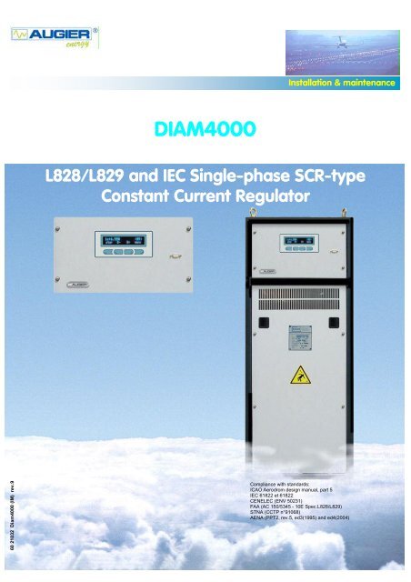
60 21032 Diam4000 (IM) rev.9 ©2004 AUGIER SA. DIAM4000 Installation & maintenance L828/L829 and IEC Single-phase SCR-type Constant Current Regulator Compliance with standards: ICAO Aerodrom design manual, part 5 IEC 61822 et 61822 CENELEC (ENV 50231) FAA (AC 150/5345 - 10E Spec.L828/L829) STNA (CCTP n°91068) AENA (PPT2, rev.5, ed3(1995) and ed4(2004) I-1
- Page 2 and 3: ©2004 AUGIER SA. RECORD OF CHANGES
- Page 4 and 5: ©2004 AUGIER SA. SAFETY Safety pre
- Page 6 and 7: ©2004 AUGIER SA. I.7 ACCESSORIES _
- Page 8 and 9: ©2004 AUGIER SA. ABBREVIATIONS Abb
- Page 10 and 11: ©2004 AUGIER SA. I.2 MECHANICAL DE
- Page 12 and 13: ©2004 AUGIER SA. I.3 ELECTRICAL DE
- Page 14 and 15: ©2004 AUGIER SA. I.4 INSTRUCTIONS
- Page 16 and 17: ©2004 AUGIER SA. I.4.2 CONTROL The
- Page 18 and 19: ©2004 AUGIER SA. I.4.4 REMOTE INFO
- Page 20 and 21: ©2004 AUGIER SA. I.5.1 CONFIGURATI
- Page 22 and 23: ©2004 AUGIER SA. I.6 SUB-ASSEMBLIE
- Page 24 and 25: ©2004 AUGIER SA. I.6.2 CUT OUT AND
- Page 26 and 27: ©2004 AUGIER SA. I.8 OPTIONS I.8.1
- Page 28 and 29: ©2004 AUGIER SA. I.8.9 4-20MA LOOP
- Page 30 and 31: ©2004 AUGIER SA. II INSTALLATION I
- Page 32 and 33: ©2004 AUGIER SA. II.2 CONNECTIONS
- Page 34 and 35: ©2004 AUGIER SA. II.2.1.4 Remote c
- Page 36 and 37: ©2004 AUGIER SA. outputs: Pin Term
- Page 38 and 39: ©2004 AUGIER SA. Terminal block T2
- Page 40 and 41: ©2004 AUGIER SA. II.2.1.5 Serial L
- Page 42 and 43: ©2004 AUGIER SA. Chronogram of ope
- Page 44 and 45: ©2004 AUGIER SA. • Protection Ea
- Page 46 and 47: ©2004 AUGIER SA. III.2 TESTS III.2
- Page 48 and 49: ©2004 AUGIER SA. IV.3 CORRECTIVE M
- Page 50 and 51: ©2004 AUGIER SA. IV.3.1.3 “Overc
60 21032 Diam4000 (IM) rev.9<br />
©2004 AUGIER SA.<br />
<strong>DIAM4000</strong><br />
Installation & maintenance<br />
<strong>L828</strong>/<strong>L829</strong> <strong>and</strong> <strong>IEC</strong> <strong>Single</strong>-<strong>phase</strong> <strong>SCR</strong>-<strong>type</strong><br />
<strong>Constant</strong> Current Regulator<br />
Compliance with st<strong>and</strong>ards:<br />
ICAO Aerodrom design manual, part 5<br />
<strong>IEC</strong> 61822 et 61822<br />
CENELEC (ENV 50231)<br />
FAA (AC 150/5345 - 10E Spec.<strong>L828</strong>/<strong>L829</strong>)<br />
STNA (CCTP n°91068)<br />
AENA (PPT2, rev.5, ed3(1995) <strong>and</strong> ed4(2004)<br />
I-1
©2004 AUGIER SA.<br />
RECORD OF CHANGES<br />
Rev. Pages Description From S/N By App. Date<br />
1.0 First issue ED RG 07/01/04<br />
1.1 V48-49 Diagrams update SC RG 15/01/04<br />
1.2 Cover composition NA RG 19/02/04<br />
1.3 Text corrections – <strong>IEC</strong> spare list – part number OE RG 08/03/04<br />
1.4 Jbus table, cabinet, ECB option ED RG 18/05/04<br />
1.5 II37-38 FAA Multiwire remote control ED RG 15/09/04<br />
1.6 II37-38 FAA Multiwire remote control, jbus table ED RG 11/10/04<br />
1.7 cover St<strong>and</strong>ard <strong>and</strong> qualification precision’s RG RG 02/11/04<br />
1.8 IV53 to V55 Spare lists <strong>and</strong> diagrams update 24 532 OE RG 24/11/04<br />
1.9 II37,38,41 Connections, interlock SC RG RG 30/11/04<br />
I-2
©2004 AUGIER SA.<br />
WARRANTIES<br />
Guarantee<br />
AUGIER’s goods are guaranteed for one year from delivery date on the signed delivery note, <strong>and</strong> are<br />
guaranteed to be free from defects in materials used, design <strong>and</strong> manufacture.<br />
The guarantee covers repair, modification or replacement of parts or products recognised to be defective, in<br />
the shortest possible time, at AUGIER’s cost, provided always that the goods have been properly h<strong>and</strong>led <strong>and</strong><br />
stored prior installation, properly installed <strong>and</strong> properly operated after installation.<br />
Unless otherwise specifically laid down in contract, the guarantee does not cover:<br />
• Costs of consignment to factory <strong>and</strong> re-consignment of defective goods to Buyer<br />
• If these are repaired in AUGIER’s factory;<br />
• Travelling & sojourn expenses of AUGIER’s personnel if goods have to be repaired on site; assembly<br />
<strong>and</strong> dismantling of any goods other than those recognised to be defective; expenses incurred for<br />
waiting times by AUGIER’s personnel on site for reasons independent of their will;<br />
• Unjustified travel expenses.<br />
Guarantee shall not apply in the following cases:<br />
• Defects in materials supplied by Buyer or from any designs imposed by them;<br />
• Repairs or replacements due to normal wear <strong>and</strong> tear, or damages or accidents.<br />
• Repairs or replacements due to damages or accidents resulting from negligence or lack of due care,<br />
inadequate supervision or maintenance, or erroneous use of the equipment or software;<br />
• Any other causes for which AUGIER shall not be held responsible, e.g. resulting from an case of Force<br />
Majeure.<br />
• When Buyer has replaced AUGIER’s parts with other parts.<br />
Buyer must inform AUGIER in writing <strong>and</strong> without delay of any defects in goods, giving all necessary<br />
information <strong>and</strong> detailed description of how equipment has been utilised, together with purchase date. Buyer<br />
undertakes not to have repairs carried out by third parties; any repairs carried out without AUGIER’s express<br />
prior agreement shall invalidate the guarantee.<br />
It is expressly agreed between the two parties that Buyer cannot avail himself of the beneficial dispositions<br />
contained in the guarantee without having first satisfied payment conditions laid down in contract<br />
Disclaimers<br />
This manual could contain technical or typographical errors. AUGIER reserves the right to make changes <strong>and</strong><br />
revise this manual from time to time without obligation to notify any person or organisation of such changes or<br />
revision.<br />
Values <strong>and</strong> measurements given in this manual are average values <strong>and</strong> are not binding. AUGIER disclaims any<br />
liability for damages suffered as a result of reliance on the information given in this manual, or the use of<br />
equipment or processes which this manual refers.<br />
No guarantee is made that the use of the products, equipment, processes or information to which this manual<br />
refers will not infringe any third party’s patent or rights. Information given does not release the buyer from<br />
making their own tests.<br />
I-3
©2004 AUGIER SA.<br />
SAFETY<br />
Safety precautions<br />
This equipment is normally used or connected to circuits that may employ dangerous <strong>and</strong> lethal voltages.<br />
Extreme caution should be exercised by operating or maintenance people when working on or with this<br />
equipment.<br />
See <strong>IEC</strong> 61820 & 61821 st<strong>and</strong>ard (CCR <strong>type</strong> <strong>IEC</strong>), or FAA AC150/5340-26 advisory circular (CCR <strong>type</strong> FAA),<br />
concerning safety rules <strong>and</strong> precautions. While practical safety precautions have been incorporated in this<br />
equipment, the following rules must be strictly observed :<br />
• KEEP AWAY FROM LIVE CIRCUITS :<br />
Operating <strong>and</strong> maintenance people must at all time observe all safety regulations. Do not change<br />
components nor perform maintenance inside equipment with power ON or the lighting loop energised.<br />
• RESUSCITATION :<br />
Operating <strong>and</strong> maintenance personnel should familiarise <strong>and</strong> keep themselves trained with resuscitation<br />
techniques found in widely published manuals about first aid instructions.<br />
• ELECTROSTATIC DISCHARGE (ESD) :<br />
Electronic sub-assemblies <strong>and</strong> boards should be touched only for unavoidable operation (replacement,<br />
for example). Before to operate, maintenance people must first of all eliminate unwanted electronic<br />
charges, discharging his own body while touching a conductive earthed object or part. Electronic boards<br />
<strong>and</strong> components as power semiconductors must be stored <strong>and</strong> carried an conductive packing.<br />
• DESTRUCTION :<br />
In case of dismantling, scrapping or placing out of service, the user must follow all the required<br />
precautions for component, materials or equipment elimination, according the local rules.<br />
EEC DIRECTIVES<br />
This equipment complies with the requirements of EC directives :<br />
• 89/336/EEC, 92/31/EEC <strong>and</strong> 93/68/EEC with regard of Electromagnetic<br />
Compatibility<br />
• 73/23/EEC with regard of Low Voltage Equipment<br />
I-4
©2004 AUGIER SA.<br />
TABLE OF CONTENTS<br />
RECORD OF CHANGE ……………………………………………………………………………………………… I-2<br />
WARRANTIES …………………………………………………………………………………………………………… I-3<br />
SAFETY ……………………………………………………………………………………………………………….….. I-4<br />
TABLE OF CONTENTS ……………………………………………………………………………………………… I-5<br />
I DE<strong>SCR</strong>IPTION _______________________________________________________ I-9<br />
I.1 OVERVIEW _______________________________________________________________________ I-9<br />
I.2 MECHANICAL DE<strong>SCR</strong>IPTION _______________________________________________________ I-10<br />
I.2.1 DE<strong>SCR</strong>IPTION ________________________________________________________________ I-10<br />
I.2.2 GENERAL MECHANICAL FEATURES _____________________________________________ I-10<br />
I.2.3 STORAGE CONDITIONS________________________________________________________ I-11<br />
I.2.4 DIMENSIONS _________________________________________________________________ I-11<br />
I.3 ELECTRICAL DE<strong>SCR</strong>IPTION________________________________________________________ I-12<br />
I.3.1 BLOCK DIAGRAMS ____________________________________________________________ I-12<br />
I.3.1.1 Overview: __________________________________________________________________ I-12<br />
I.3.1.2 Electronic: __________________________________________________________________ I-12<br />
I.3.2 GENERAL CIRCUIT DIAGRAMS__________________________________________________ I-12<br />
I.3.3 GENERAL ELECTRICAL FEATURES ______________________________________________ I-13<br />
I.4 INSTRUCTIONS FOR USE __________________________________________________________ I-14<br />
I.4.1 USER INTERFACE_____________________________________________________________ I-14<br />
I.4.2 CONTROL ___________________________________________________________________ I-16<br />
I.4.3 LOCAL INFORMATION FEEDBACK _______________________________________________ I-16<br />
I.4.4 REMOTE INFORMATION FEEDBACK _____________________________________________ I-18<br />
I.5 OPERATION _____________________________________________________________________ I-19<br />
I.5.1 CONFIGURATION _____________________________________________________________ I-20<br />
I.5.2 SETTING ____________________________________________________________________ I-20<br />
I.5.2.1 Current range: _______________________________________________________________ I-20<br />
I.5.3 PROTECTIONS _______________________________________________________________ I-20<br />
I.5.3.1 LV power monitoring: _________________________________________________________ I-20<br />
I.5.3.2 “Open circuit”: _______________________________________________________________ I-20<br />
I.5.3.3 “Overcurrent”: _______________________________________________________________ I-21<br />
I.5.3.4 Cancelling “Open circuit” <strong>and</strong> “Overcurrent” faults:___________________________________ I-21<br />
I.5.4 AUTOMATIC OPERATION: ______________________________________________________ I-21<br />
I.6 SUB-ASSEMBLIES ________________________________________________________________ I-22<br />
I.6.1 LOAD PLATE _________________________________________________________________ I-22<br />
I.6.1.1 Adaptation to load: ___________________________________________________________ I-22<br />
I.6.1.2 Computation of the output voltage <strong>and</strong> output power: ________________________________ I-23<br />
I.6.2 CUT OUT AND EARTHING PLATE (OPTION) _______________________________________ I-24<br />
I.6.2.1 Normal position : _____________________________________________________________ I-24<br />
I.6.2.2 Safety position: ______________________________________________________________ I-24<br />
I.6.2.3 Load measurements:__________________________________________________________ I-24<br />
I-5
©2004 AUGIER SA.<br />
I.7 ACCESSORIES ___________________________________________________________________ I-25<br />
I.7.1 “ALIZE4000” SOFTWARE _______________________________________________________ I-25<br />
I.7.2 “RDTS4000” SOFTWARE _______________________________________________________ I-25<br />
I.8 OPTIONS ________________________________________________________________________ I-26<br />
I.8.1 EARTH FAULT DETECTOR (EFD) ________________________________________________ I-26<br />
I.8.2 OPTIONAL ISOLATING DEVICES_________________________________________________ I-26<br />
I.8.2.1 Cut-out <strong>and</strong> earthing plate : See 1.6.2 ____________________________________________ I-26<br />
I.8.2.2 FAA cut-out plug:_____________________________________________________________ I-26<br />
I.8.3 OUTPUT LIGHTNING ARRESTORS _______________________________________________ I-26<br />
I.8.4 INPUT LIGHTNING ARRESTORS _________________________________________________ I-26<br />
I.8.5 CASTERS ____________________________________________________________________ I-26<br />
I.8.6 BURNT LAMPS DETECTION: ____________________________________________________ I-27<br />
I.8.7 OUTPUT POWER DROP DETECTION: ____________________________________________ I-27<br />
I.8.8 TIME METERS: _______________________________________________________________ I-27<br />
I.8.9 4-20MA LOOP CURRENT : ______________________________________________________ I-28<br />
I.8.9.1 4-20mA current loop for output current <strong>and</strong> power measurements : _____________________ I-28<br />
I.8.9.2 4-20mA loop current (ground insulation):__________________________________________ I-28<br />
I.8.10 BUZZER _____________________________________________________________________ I-29<br />
I.8.11 WIG WAG ____________________________________________________________________ I-29<br />
I.8.12 OTHER OPTIONS _____________________________________________________________ I-29<br />
II INSTALLATION _____________________________________________________ II-30<br />
II.1 PREPARATION ___________________________________________________________________ II-30<br />
II.1.1 EQUIPMENT RECEPTION ______________________________________________________ II-30<br />
II.1.1.1 Equipment delivered:________________________________________________________ II-30<br />
II.1.1.2 Checking the equipment:_____________________________________________________ II-30<br />
II.1.2 DEVICE LOCATION ____________________________________________________________ II-30<br />
II.1.3 CHECKING THE INSTALLATION _________________________________________________ II-31<br />
II.1.3.1 <strong>Single</strong> <strong>phase</strong> power supply:___________________________________________________ II-31<br />
II.1.3.2 LV Protection: _____________________________________________________________ II-31<br />
II.1.3.3 Lighting loop: ______________________________________________________________ II-31<br />
II.1.3.4 Management by remote control: _______________________________________________ II-31<br />
II.2 CONNECTIONS___________________________________________________________________ II-32<br />
II.2.1 ELECTRICAL _________________________________________________________________ II-32<br />
II.2.1.1 LV supply: ________________________________________________________________ II-32<br />
II.2.1.2 Earthing __________________________________________________________________ II-32<br />
The Main Earth circuit must be connected to the earthing stud situated in the lower part of the frame at left<br />
(external or internal connection, at rear) __________________________________________________ II-32<br />
II.2.1.3 Lighting loop: ______________________________________________________________ II-33<br />
II.2.1.4 Remote control connections __________________________________________________ II-34<br />
II.2.1.4.1 CONFIGURATION OF REMOTE CONTROL TYPE________________________________ II-34<br />
II.2.1.4.2 FAA Multiwire remote control (FAA <strong>type</strong> CCRs only, with 20 to 60Vdc inputs))___________ II-35<br />
II.2.1.4.3 <strong>IEC</strong> Multiwire remote control (<strong>IEC</strong> <strong>type</strong> CCRs only): _______________________________ II-37<br />
II.2.1.4.4 Operating modes for multiwire (FAA & <strong>IEC</strong>) remote control : _________________________ II-39<br />
I-6
©2004 AUGIER SA.<br />
II.2.1.5 Serial Link: ________________________________________________________________ II-40<br />
II.2.1.6 Circuit selector: ____________________________________________________________ II-41<br />
II.3 ADJUSTING THE CCR _____________________________________________________________ II-43<br />
II.3.1 ADAPTATION TO LOAD ________________________________________________________ II-43<br />
II.3.1.1 Maximum power levels by power settings: _______________________________________ II-43<br />
II.3.2 PARAMETER MODIFICATION ___________________________________________________ II-43<br />
II.3.2.1 Preferred configuration values: ________________________________________________ II-43<br />
II.3.2.2 Brightness values: __________________________________________________________ II-44<br />
II.3.2.3 Value of “Open Circuit” protection level: _________________________________________ II-44<br />
II.3.2.4 Value of “Overcurrent” protection levels:_________________________________________ II-44<br />
III COMMISSIONING _________________________________________________ III-45<br />
III.1 PROCEDURE ___________________________________________________________________ III-45<br />
III.2 TESTS _________________________________________________________________________ III-46<br />
III.2.1 SHORT-CIRCUIT TESTS_______________________________________________________ III-46<br />
III.2.2 OVERLOAD TESTS ___________________________________________________________ III-46<br />
III.2.3 OPEN-CIRCUIT TEST _________________________________________________________ III-46<br />
IV MAINTENANCE___________________________________________________ IV-47<br />
IV.1 FORMALISATION ________________________________________________________________ IV-47<br />
IV.2 PREVENTIVE ___________________________________________________________________ IV-47<br />
IV.2.1 FIRST MONTHS ______________________________________________________________ IV-47<br />
IV.2.2 ANNUAL PROCEDURE ________________________________________________________ IV-47<br />
IV.2.3 EVERY THREE YEARS ________________________________________________________ IV-47<br />
IV.3 CORRECTIVE ___________________________________________________________________ IV-48<br />
IV.3.1 FAULT DIAGNOSIS ___________________________________________________________ IV-48<br />
IV.3.1.1 LV power fault:____________________________________________________________ IV-48<br />
IV.3.1.2 “Open Circuit” fault: ________________________________________________________ IV-49<br />
IV.3.1.3 “Overcurrent” fault:_________________________________________________________ IV-50<br />
IV.3.2 OTHER FAULTS______________________________________________________________ IV-51<br />
IV.4 VERIFICATION PROCEDURES _____________________________________________________ IV-52<br />
IV.4.1 THYRISTORS________________________________________________________________ IV-52<br />
IV.5 SPARE PARTS LIST FOR FAA TYPE CCR ___________________________________________ IV-52<br />
IV.6 SPARE PARTS LIST FOR <strong>IEC</strong> TYPE CCR ____________________________________________ IV-55<br />
V APPENDIX A: DIAGRAMS ____________________________________________ V-56<br />
VI APPENDIX B: JBUS TABLE_________________________________________ VI-58<br />
VII APPENDIX C: PART NUMBER IDENTIFICATION ________________________ VII-66<br />
I-7
©2004 AUGIER SA.<br />
ABBREVIATIONS<br />
Abbreviation Definition<br />
A Ampere<br />
AC Alternating Current<br />
B Brightness<br />
CCR <strong>Constant</strong> Current Regulator<br />
DC Direct Current<br />
EFD Earth Fault Detector<br />
HV High Voltage<br />
IT Injection Transformer<br />
LFD Lamp Fault Detector<br />
LV Low Voltage<br />
OO Out of order<br />
V Volt<br />
VA Volt-Ampere<br />
I-8
©2004 AUGIER SA.<br />
I DE<strong>SCR</strong>IPTION<br />
I.1 OVERVIEW<br />
<strong>DIAM4000</strong> series CCRs are low costs fully static devices controlled by two thyristors (anti-parallel mounting<br />
<strong>type</strong> dimmer). They are designed to maintain a constant, pre-displayed <strong>and</strong> adjustable output current<br />
independently of the load <strong>and</strong> power supply fluctuations.<br />
These devices are specifically designed for airfield lighting on runways, taxiways, aprons. They meet both<br />
national <strong>and</strong> international st<strong>and</strong>ards.<br />
In order to do this, they use an adapted triggering <strong>and</strong> regulation mechanism that is not affected by external<br />
interference <strong>and</strong> does not emit measurable interference in the Aviation B<strong>and</strong> between 100 <strong>and</strong> 400 MHz.<br />
This <strong>type</strong> of regulator uses natural air-cooling. The output current remains constant with an accuracy of 1%<br />
for mains voltage fluctuations of –5/+10% (+/-10% for <strong>IEC</strong> <strong>type</strong>). At the rated load <strong>and</strong> the rated or higher<br />
voltage, accuracy of regulation is maintained for all load between 0 <strong>and</strong> 100%, <strong>and</strong> for up to 30% of<br />
transformers with open secondary. The output power of the regulator can be adjusted to the load by means of<br />
transformers taps, by steps of 12.5%.<br />
Here are some of its advantages:<br />
• Flexibility of use:<br />
The alphanumeric display <strong>and</strong> menu <strong>type</strong> keyboard allow the CCR to be configured without connection<br />
with a computer.<br />
Regulation is fully digital which enables parameters to be simply modified for a particular load.<br />
Emergency <strong>and</strong> warning messages are clearly displayed.<br />
• Simplicity:<br />
CCR <strong>type</strong> regulators have a very simplified architecture both for the electronic control unit <strong>and</strong> the LV<br />
<strong>and</strong> HV power parts.<br />
• Adaptability <strong>and</strong> safety:<br />
An optional Cut-out <strong>and</strong> Earthing plate, using two pluggable jumpers can be used to disconnect the<br />
CCR from the loop, to earth or short-circuit the loop without disconnecting the load at any time.<br />
• Construction:<br />
It has been optimised to keep the number <strong>and</strong> variety of spare parts to a minimum. The device is made<br />
up of modular sub-assemblies.<br />
• St<strong>and</strong>ards:<br />
ƒ ICAO: Airport design manual, part 5<br />
ƒ STNA: CCTP 91068 rev.93<br />
ƒ CENELEC: prENV 50231<br />
ƒ FAA: AC150/5345-10 E, <strong>L828</strong> or <strong>L829</strong><br />
ƒ AENA: PPT NTA2-rev.5 (1995) & ed.4 (2004)<br />
ƒ <strong>IEC</strong>: 61822 (CCRs), 61821 (Maintenance)<br />
I-9
©2004 AUGIER SA.<br />
I.2 MECHANICAL<br />
DE<strong>SCR</strong>IPTION<br />
I.2.1 DE<strong>SCR</strong>IPTION<br />
Each CCR is housed in a cabinet fitted with lifting rings. The frame has three distinct parts: an “electronic”<br />
control part, a “low voltage” compartment <strong>and</strong> a “high voltage” compartment.<br />
• The Electronic unit of the CCR consists of a main electronic circuit board fitted to the upper panel of the<br />
cabinet.<br />
All the basic functions of the regulator are included in the electronic compartment <strong>and</strong> are accessible from<br />
the front <strong>and</strong> the top of the CCR.<br />
• The Low voltage unit contains all the components connected to the power supply with, for example, the<br />
thyristors <strong>and</strong> associated driver boards, the master switch, the LV fuses <strong>and</strong> connection terminals. It is<br />
located in the upper part of the CCR.<br />
• The High voltage unit, situated at the back of the CCR, contains all the components connected to the<br />
output loop such as the power transformer, the lightning arrestors, the CI-MALT (optional) <strong>and</strong> the HV part<br />
of the insulation fault detection unit. The load regulating plate <strong>and</strong> the load loop connections are accessible<br />
from the front of the device.<br />
All these components are easily accessible from the front, the top or the back of the cabinet.<br />
I.2.2 GENERAL MECHANICAL FEATURES<br />
Regulators are contained in the same cabinet for all powers <strong>and</strong> input voltage. A taller one (+ 20cm) is available<br />
when inside additional equipment is requested by customer, as ECB (*) option. Both cabinets are provided with<br />
hoisting eye rings, with or without casters, <strong>and</strong> can be located cuddled up to each other.<br />
St<strong>and</strong>ard cabinet : 500mm Wide x 700mm Deep x 1380mm High<br />
Big cabinet : 500mm Wide x 700mm Deep x 1580mm High<br />
• Protection Index for the Casing: IP 21. (Contact us for other Protection Indices)<br />
• Distances inter-axes (if casters option) : 355 x 610 mm<br />
• Usage: Ambient temperature between -40°C <strong>and</strong> +55°C (FAA <strong>type</strong>) or –20°C to +55°C (<strong>IEC</strong> <strong>type</strong>),<br />
with maximum relative humidity of 95%. Natural air cooling.<br />
(*) ECB : Loop Communication Equipment, <strong>type</strong> STB or SCB (Please ask for more informations)<br />
I-10
©2004 AUGIER SA.<br />
I.2.3 STORAGE CONDITIONS<br />
The components are designed to be stored in a dry, airy location, sheltered from rain, water discharges<br />
<strong>and</strong> chemical agents. We must be consulted if the components are to be stored outside, or in an ambient<br />
temperature out of the range -40°C/+55°C.<br />
I.2.4 DIMENSIONS<br />
A<br />
A(mm) B(mm) C(mm)<br />
1 to 30 kVA 1380 500 700<br />
With ECB (*) 1580 500 700<br />
Load 2,5kVA 4kVA 5kVA 7,5kVA 10kVA 15kVA 20kVA 25kVA 30kVA<br />
Weight 135 kg 155kg 155kg 170kg 175kg 220kg 280kg 295kg 330kg<br />
(*) ECB : Loop Communication Equipment<br />
B<br />
C<br />
I-11
©2004 AUGIER SA.<br />
I.3 ELECTRICAL<br />
DE<strong>SCR</strong>IPTION<br />
I.3.1 BLOCK DIAGRAMS<br />
L See paragraph I.5 for the device operating description<br />
Input<br />
circuits<br />
I.3.1.1 Overview:<br />
I.3.1.2 Electronic:<br />
RS232/RS485<br />
Power supply<br />
I.3.2 GENERAL CIRCUIT DIAGRAMS<br />
L See Appendix A<br />
Main<br />
Contactor<br />
Settings<br />
DIAM<br />
Daughter Board<br />
DIAM Motherboard<br />
EFD Data<br />
Interfaces<br />
Control &<br />
Monitoring<br />
Thyristors<br />
dimmer<br />
Measurements<br />
Measuring<br />
Board<br />
LV/HV<br />
Transformer<br />
Thyristor control<br />
board<br />
Measurement Board<br />
Output<br />
circuits<br />
Current,<br />
Voltage<br />
Keyboard<br />
Display<br />
I-12
©2004 AUGIER SA.<br />
I.3.3 GENERAL ELECTRICAL FEATURES<br />
• Power supply voltage:<br />
<strong>Single</strong> <strong>phase</strong>; two series :<br />
FAA <strong>type</strong> : 208Vac, 220Vac, 240Vac, 277Vac, 400Vac, 480Vac –5/+10%, 50 or 60 Hz ±5%.<br />
<strong>IEC</strong> <strong>type</strong> : 220Vac, 230Vac, 240Vac, 380Vac, 400Vac, 415Vac +10/-10%, 50 or 60Hz ±5%<br />
• Maximum rated current: 6.6 A (other values available).<br />
• Number of Brightness Levels: maximum 8, adjustable.<br />
• Heating Brightness (“Black current”):<br />
The CCR can produce “heating” level brightness at low current (1.5A prefered), which is used to remove<br />
condensation from the interior of the lamp lenses without lighting up their bulb. The symbol for local<br />
setting is ‘B0’.<br />
• Remote Control: By voltage from 20V to 60V DC positive or negative, or dry contact, or 120Vac,<br />
<strong>and</strong>/or serial network.<br />
• Remote indication:<br />
FAA <strong>type</strong> : Relays, 120VAC , 2A max, 10µA min., <strong>and</strong>/or serial network<br />
<strong>IEC</strong> <strong>type</strong> : Static dry contacts relays, 48Vdc, 0.1A max, <strong>and</strong>/or serial network<br />
• Output power: 1, 2.5, 4, 5, 7.5, 10, 15, 20, 25, 30 kVA<br />
• Power factor:<br />
FAA <strong>type</strong> : > 90% (2.5 to 10kW CCRs) or > 95% (15 to 30kW CCRs), at voltage <strong>and</strong> rated resistive load<br />
<strong>IEC</strong> <strong>type</strong> : > 90% at nominal voltage <strong>and</strong> rated resistive load<br />
• Efficiency : > 90% at nominal voltage <strong>and</strong> rated resistive load.<br />
• Output Current Regulation:<br />
Better than ±1% under the following conditions: Power supply voltage: ± 10% (<strong>IEC</strong>) or –5/+10% (FAA) -<br />
Frequency: ± 5% - Load: from 0 to 100%<br />
• Load adaptation:<br />
The output transformer is equipped with an epoxy plate including adjustment taps in order to adapt the<br />
rated output voltage of the CCR to the present load. Two brass straps allow load adaptation with steps<br />
of 12.5%, between 12.5% <strong>and</strong> 100% (8 possibilities).<br />
• Protection:<br />
The electronic circuitry is protected against fluctuations by the use of a Hall effect sensor for measuring<br />
current, <strong>and</strong> fibre optics for thyristors control. Electronic board manages all overcurrent, open circuit or<br />
mains under/over voltage.<br />
• LV Protection:<br />
A set of high-power fuses (or optional circuit breaker), a set of fuses for the power supply to the<br />
auxiliaries, <strong>and</strong> “glass” fuses on the circuit boards provide LV protection.<br />
• Lightning arrestors :<br />
These regulators can be optionally provided with input <strong>and</strong> output lightning arrestors.<br />
I-13
©2004 AUGIER SA.<br />
I.4 INSTRUCTIONS FOR USE<br />
I.4.1 USER INTERFACE<br />
Operating mode:<br />
Stop mode :<br />
Io:0.00A STOP<br />
stop local auto menu<br />
Preferred information displayed: they can be changed by a long press on the “STOP” key, meanwhile the CCR<br />
is in Stop mode. The choice can be :<br />
• Output current Io – Brightness state Bx (as seen in examples below <strong>and</strong> above)<br />
• Output current Io – Output power Po<br />
• Output current Io – Output voltage Uo<br />
Local mode :<br />
Io:6.60A <br />
stop B- B+ menu<br />
Access is given to B+ <strong>and</strong> B-, in order to increase / decrease the brightness.<br />
Remote control mode :<br />
Io:5.20A <br />
stop local auto menu<br />
“Auto” is highlighted, in order to indicate the current state.<br />
Brightness selection in local mode:<br />
Io:6.60A <br />
stop B- B+ menu<br />
:Decrease brightness in local mode Increase brightness in local mode<br />
I-14
©2004 AUGIER SA.<br />
Menus:<br />
Io:0.00A STOP<br />
stop local auto menu<br />
Access to menu<br />
Monitoring<br />
esc OK<br />
Alarms <strong>and</strong> Warnings:<br />
To navigate in the menus<br />
Alarm (the CCR failed to supply the load); for example, the CCR is stopped by a loop open circuit :<br />
ALARM: I
©2004 AUGIER SA.<br />
I.4.2 CONTROL<br />
The device is controlled by mean of a 4 buttons keypad which allows to change the operating mode: “Stop” –<br />
Manual or “Local” mode – Remote or “Auto” control mode.<br />
• Stop mode:<br />
Io:0.00A STOP<br />
stop local auto menu<br />
In that mode, “Stop” is highlighted. The CCR stops, whatever the current brightness orders (remote control or<br />
local selection).<br />
Menus can then be accessed.<br />
• Local mode:<br />
Io:6.60A <br />
stop B- B+ menu<br />
In that mode appears brightness controls : The brightness is chosen by pressing buttons B- <strong>and</strong> B+ (from B0 to<br />
B7 maximum, according to the number of brightness levels configured).<br />
• Remote control mode:<br />
Io:0.00A <br />
stop local auto menu<br />
In that mode, “Auto” is highlighted. Operation of the CCR is governed by remote control inputs on the CCR’s<br />
motherboard. If remote control comm<strong>and</strong>s overlap, priority is given to the first choice of brightness. The remote<br />
control is either of the multiwire <strong>type</strong> (20 to 60 DC positive or negative, or 120Vac), or the dry-contact <strong>type</strong> with<br />
internal power supply, <strong>and</strong>/or given by the mean of a serial network.<br />
L See paragraph II.3 for configuring the remote control <strong>type</strong>.<br />
L See paragraph II.3 for adjusting brightness values <strong>and</strong> protection levels.<br />
I.4.3 LOCAL INFORMATION FEEDBACK<br />
Alphanumeric display:<br />
• The display shows the RMS current flowing in the loop <strong>and</strong> the selected brightness (preferably).<br />
In the “Monitoring” menu, the following information are shown:<br />
• Uo: RMS output voltage in Vrms<br />
• Po: RMS output power in KVA<br />
• Ui: Mains power supply voltage in Vrms<br />
• If option “EFD” exists: Insulation resistance of the loop with respect to earth in KOhms<br />
• Load plate tap value from 0 to 100% (0 to 8/8 by increments of 1/8)<br />
• If option “LFD” exists: Number of burnt lamps, <strong>and</strong> VA drop if FAA <strong>type</strong><br />
• The operating time (powered on <strong>and</strong> for each brightness) in Hours<br />
I-16
©2004 AUGIER SA.<br />
Warning:<br />
WARNING is an indicative message, which does not change regulation <strong>and</strong> supply function in connection with<br />
the load. (Except for mains warning)<br />
If any warning have been detected, the following message(s) can be shown on the display:<br />
• If option “EFD” exists:<br />
“No HV (500V) EFD” (no injection voltage : measurement of earth leakage cannot be done)<br />
“R Level EFD1” (A leakage has been detected, with a resistance value lower than the level 1).<br />
“R Level EFD2” (A leakage has been detected, with a resistance value lower than the level 2).<br />
• If option “Burnt lamps” exists:<br />
“Level 1 Burnt lamps” (The current number of burnt lamps is greater than level 1)<br />
“Level 2 Burnt lamps” (The current number of burnt lamps is greater than level 2)<br />
“Power drop” (if FAA selected : the load was cut more than 10%, in VA)<br />
• Mains power supply outside limits (Input voltage lower or greater than +/-10%)<br />
• Regulation outside limits (as “error regulation” programmed values)<br />
Fault:<br />
ALARM represents a major fault of the CCR or due to an external event, which have stopped the CCR (in order<br />
to protect itself or the lighting loop).<br />
In case of fault or damage, the display shows that the CCR stopped <strong>and</strong> one or more faults have been detected.<br />
The following message(s) are shown on the display:<br />
• Overcurrent Level 1 (after a trial to restart, the CCR cannot contain the output current which had reach<br />
the 1 st level as programmed)<br />
• Overcurrent Level 2 (ditto, for 2 nd level)<br />
• Overcurrent Level 3 (ditto, for 3 rd level)<br />
• Peak Overcurrent (ditto, for a 4 th level, not configurable)<br />
• Open circuit (the CCR detected an output current lower <strong>and</strong> during a greater time than the programmed<br />
parameters)<br />
In order to re-start (after having fixed the fault), cancel the ALARM pressing the RESET key.<br />
I-17
©2004 AUGIER SA.<br />
I.4.4 REMOTE INFORMATION FEEDBACK<br />
Dry contacts:<br />
Information returned:<br />
• Selected brightness<br />
• Operating mode: Local/Remote control<br />
• “Open Circuit” fault<br />
• “Overcurrent” fault<br />
• If option “EFD” appears: EFD Level 1 <strong>and</strong> 2 warnings<br />
• If option “Burnt lamps” appears: Burnt lamps level 1 <strong>and</strong> 2 warnings<br />
• If option “Burnt lamps” <strong>and</strong> FAA <strong>type</strong>: Power drop<br />
L See the “Remote control terminal block” connection table in the appendix.<br />
Insulated JBUS RS232 or RS485 link:<br />
A JBUS table is accessible via an insulated JBUS RS485 link (1 RS485 option) or through the front 9pins SubD<br />
socket.<br />
The values in the table are used to control <strong>and</strong> monitor the device remotely.<br />
L See the JBUS table in the appendix for more details.<br />
I-18
©2004 AUGIER SA.<br />
I.5 OPERATION<br />
L The “Parameter Access” function must be activated before changing parameters, in order to<br />
avoid unwanted changes.<br />
Pressing the menu touch, the display shows:<br />
Monitoring<br />
esc OK<br />
then scroll through the top-level menu items using the <strong>and</strong> keys. When the “Options” item is shown<br />
like:<br />
Options<br />
esc OK<br />
press OK to go into the “Options” menu, then scroll through the items until the “Param. access: NO” item is<br />
displayed:<br />
Param. access: No<br />
esc modif<br />
Press modif in order to modify the parameter. When the "NO" displayed blinks, it is possible to change the<br />
parameter : press < or > to in order to change “NO” to “YES” :<br />
Param. access: Yes<br />
esc OK<br />
Save the modification by pressing OK .<br />
Press esc twice to go back to the initial state.<br />
ALL PARAMETERS ARE MODIFIED USING THE SAME PROCEDURE.<br />
I-19
©2004 AUGIER SA.<br />
I.5.1 CONFIGURATION<br />
The “Configuration” menu is used to define the basic parameters of the CCR (for example when replacing the<br />
main board):<br />
• Rated mains voltage in Vrms: 208-220-230-240-277-380-400-415-480<br />
• Rated power in KVA:1-2.5-4-5-7.5-10-15-20-25-30<br />
• Number of brightness (Including B0): from 1 to 8<br />
• Mains frequency in Hz: 50 or 60<br />
• FAA or <strong>IEC</strong> <strong>type</strong><br />
I.5.2 SETTING<br />
The “Setting” menu is used to assign values of current to brightness levels B0 to B7.<br />
• Minimum value = 1Arms<br />
• Maximum value = 6.8Arms<br />
I.5.2.1 Current range:<br />
The “Regulation Error” warning is triggered if the measured current is outside the ranges defined for each<br />
setting B0 to B7.<br />
Each range is automatically calculated when a setting is changed (as described below) in the following way:<br />
• Minimum value = Setting – 3%<br />
• Maximum value = Setting +3%<br />
Nevertheless it is possible to set two limits of the current range manually using the “Current range” menu.<br />
I.5.3 PROTECTIONS<br />
I.5.3.1 LV power monitoring:<br />
Mains voltage Duration CCR status<br />
Ui < 75% of rated voltage 0s CCR stops (Power supply Warning)<br />
Ui > 130% of rated voltage 0s CCR stops (Power supply warning)<br />
Ui < 85% of rated voltage 60s CCR stops (Power supply warning)<br />
Ui > 120% of rated voltage 60s CCR stops (Power supply warning)<br />
90% < Ui < 110% of rated voltage 0s CCR automatically restarts<br />
I.5.3.2 “Open circuit”:<br />
Open Circuit Protection is activated if the output current goes below a defined value (I level OC) for a<br />
defined period (Duration OC). The CCR stops instantly, <strong>and</strong> the display shows the message “Open Circuit”.<br />
Setting I level OC <strong>and</strong> Duration OC:<br />
Go into the menu “Alarms <strong>and</strong> Warnings” then “Open Circuit”.<br />
I-20
©2004 AUGIER SA.<br />
I.5.3.3 “Overcurrent”:<br />
Overcurrent protection is activated if the output current goes above a defined value for a defined period.<br />
There are three adjustable Overcurrent levels:<br />
Setting current levels I>> Level 1, I>> Level 2, I>> Level 3, Duration IL1, Duration IL 2, Duration IL 3 :<br />
Go into the menu “Alarms <strong>and</strong> Warnings” then “Overcurrent”.<br />
There is a fourth level, which is not adjustable : The fault “Peak Overcurrent!” occurs if the output current<br />
goes instantly above twice the nominal peak current (see <strong>IEC</strong> definition).<br />
An Overcurrent fault can be automatically cancelled according to the value of the “Restarts number”<br />
parameter.<br />
As each fault occurs, the number of faults is incremented. If the number of faults is greater than or equal to<br />
“Restarts number” in a period of less than 10s the fault is activated. The number of faults is reset to 0 after 10s<br />
without fault.<br />
If the programmed number of restarts is reached without control of the current, the CCR stops instantly,<br />
<strong>and</strong> the display shows which level has been reached.<br />
Setting the “Restarts number” parameter :<br />
Go into the menu “Alarms <strong>and</strong> Warnings” then “Overcurrent”.<br />
I.5.3.4 Cancelling “Open circuit” <strong>and</strong> “Overcurrent” faults:<br />
Faults are memorised during a mains power loss :<br />
Alarm message<br />
ALARM: I
©2004 AUGIER SA.<br />
I.6 SUB-ASSEMBLIES<br />
I.6.1 LOAD PLATE<br />
The main function of the load adaptation plate is to adjust the power of the CCR to the installed power of<br />
the lighting loop..<br />
The load plate can be accessed from the front of the device. Opening the panel forces the CCR to stop by<br />
the mean of door contact.<br />
The value of the present tap of the load adaptation plate can be seen in the menu “Monitoring” then “Load<br />
tapping”:<br />
Load tapping: 8/8<br />
esc<br />
I.6.1.1 Adaptation to load:<br />
The transformer comprises output connections which allow 8 settings from 12.5% (1/8 load) to 100%<br />
(8/8). Two brass straps are used for this.<br />
Examples :<br />
• One strap carries out adjustments in steps of 25% (100%,75%,50%,25%)<br />
• The other carries out a supplementary adjustment of 0 or –12.5%, which is added to the preceding<br />
value.<br />
100% Load tapping: 8/8 87.5% Load tapping: 7/8<br />
8/8<br />
6/8<br />
4/8<br />
2/8<br />
-1/8 0<br />
8/8<br />
6/8<br />
4/8<br />
2/8<br />
-1/8 0<br />
75% Load tapping: 6/8 62.5% Load tapping: 5/8<br />
8/8<br />
6/8<br />
4/8<br />
2/8<br />
-1/8 0<br />
8/8<br />
6/8<br />
4/8<br />
2/8<br />
-1/8 0<br />
I-22
©2004 AUGIER SA.<br />
50% Load tapping: 4/8 37.5% Load tapping: 3/8<br />
8/8<br />
6/8<br />
4/8<br />
2/8<br />
-1/8 0<br />
25% Load tapping: 2/8 12.5% Load tapping: 1/8<br />
8/8<br />
6/8<br />
4/8<br />
2/8<br />
-1/8 0<br />
I.6.1.2 Computation of the output voltage <strong>and</strong> output power:<br />
To calculate correctly the output voltage <strong>and</strong> output power in VA, it is necessary to inform the<br />
microprocessor about the position of the tap used (as above)<br />
In order to set this parameter, go in the "Configuration" menu:<br />
Configuration<br />
esc OK<br />
Press OK <strong>and</strong> scroll the items until the display seems like:<br />
Load tapping: 8/8<br />
esc modif<br />
Press the modif touch to change the load tapping between 1/8 <strong>and</strong> 8/8 <strong>and</strong> press OK to validate<br />
L If the modif touch doesn’t appear, the parameters access is locked : see paragraph I.5 (Operations) in<br />
order to access to parameters’ modification.<br />
8/8<br />
6/8<br />
4/8<br />
2/8<br />
-1/8 0<br />
8/8<br />
6/8<br />
4/8<br />
2/8<br />
-1/8 0<br />
I-23
©2004 AUGIER SA.<br />
I.6.2 CUT OUT AND EARTHING PLATE (OPTION)<br />
AUGIER’s experience regarding CCRs has been used to simplify the HV compartment <strong>and</strong> maintenance<br />
operations to the maximum.<br />
With that option, the CCR is equipped with an cut-out <strong>and</strong> earthing plate, using two jumpers which allows<br />
to carry out all maintenance <strong>and</strong> measurement operations, without unscrewing any load terminal or earth<br />
connection, <strong>and</strong> without requiring any special tools.<br />
I.6.2.1 Normal position :<br />
It is the operational position.<br />
If the two 3 pins jumpers are in that position (vertically), the loop’s terminals are<br />
linked to the output of the CCR :<br />
I.6.2.2 Safety position:<br />
By removing the two jumpers from the previous operating position as above, the CCR will be<br />
disconnected from the loop in a safe <strong>and</strong> clearly visible way. Then, placing the two jumpers in horizontal<br />
position, CCR’s output <strong>and</strong> the two loop’s terminals (still isolated) will be shortcircuited,<br />
while the third pin of each jumper make an earth connection.<br />
L This is the safe position, allowing works to be carried out on the field : CCR<br />
is short-circuited to the earth, <strong>and</strong> separately from the loop, also shortcircuited<br />
<strong>and</strong> earthed.<br />
L WARNING : Although the CCR <strong>and</strong> the loop are earthed, the CCR can be<br />
switched ON : In that case, it regulates a constant current through the upper<br />
jumper.<br />
I.6.2.3 Load measurements:<br />
Removing the lower jumper, CCR will be still short-circuited <strong>and</strong> earthed, but loop’s terminals will be let<br />
free, in order to allow to proceed at all insulation <strong>and</strong> continuity measurements, which can be carried out as well<br />
as any other testing or research operations concerning the load.<br />
L This is the measurement position of the cut-out plate.<br />
L WARNING : Although the CCR <strong>and</strong> the loop are isolated, the CCR can be switched ON : In the case<br />
where the two jumpers are removed, it should fail in “Open Circuit”.<br />
CAUTION:<br />
In order to avoid damaging the pins of the jumpers, do not push or pull it<br />
asymmetrically from the sockets : They must be placed or withdrawn with the two<br />
h<strong>and</strong>s, distributing efforts at each end so that its movement remains perpendicular to<br />
the plate, the body remaining parallel with the plate.<br />
I-24
©2004 AUGIER SA.<br />
I.7 ACCESSORIES<br />
I.7.1 “ALIZE4000” SOFTWARE<br />
The CCR is configured in factory but its parameters can be changed directly on the equipment without<br />
using any special accessories. The CCR can also be configured via a PC-<strong>type</strong> computer linked to the RS232<br />
socket on the front of the device.<br />
The free software, called “ALIZE4000”, allows to :<br />
• Configure the device <strong>and</strong> save or retrieve the parameters in a file.<br />
• Download the CCR’s own software (For updates)<br />
• Help maintenance people in fault diagnosis (Displaying internal voltages, state of inputs/outputs,<br />
etc).<br />
• Test <strong>and</strong> monitor the CCR, allowing to send remote orders <strong>and</strong> to see its back indication.<br />
Note : ALIZE4000 is an enhanced release of ALIZE3000, allowing to operate on both DIAMANT series<br />
as <strong>DIAM4000</strong> series CCRs. (the software will recognise automatically the <strong>type</strong> of CCR)<br />
I.7.2 “RDTS4000” SOFTWARE<br />
the Regulator Diagnosis <strong>and</strong> Test Software RDTS4000 is a maintenance software allowing to test all<br />
functions <strong>and</strong> sub-assemblies of the CCR, to calibrate measurements <strong>and</strong> check inputs <strong>and</strong> outputs of<br />
electronic boards.<br />
Note : RDTS4000 is an enhanced release of RDTS3000, allowing to operate on both DIAMANT series<br />
as <strong>DIAM4000</strong> series CCRs. (the software will recognise automatically the <strong>type</strong> of CCR)<br />
I-25
©2004 AUGIER SA.<br />
I.8 OPTIONS<br />
I.8.1 EARTH FAULT DETECTOR (EFD)<br />
This option is used to measure the insulation of the load with respect to earth.<br />
The insulation controller, or “earth fault detector” continually checks the electrical resistance between<br />
the loop <strong>and</strong> earth. It uses the principle of continuous current injection at 500V <strong>and</strong> its range of measurement is<br />
between 1 kΩ <strong>and</strong> 10 MΩ.<br />
The insulation resistance value can be seen in the “Monitoring” menu<br />
Two comparison levels (warning <strong>and</strong> alarm) are available. They are preferably set at 1MΩ <strong>and</strong> 100kΩ.<br />
Setting the Level EFD1 <strong>and</strong> Level EFD2 parameters:<br />
Go into the menu “Alarms <strong>and</strong> Warnings” then “Earth fault”.<br />
Remote indication :<br />
• Each level passed is indicated by a contact relay<br />
• The insulation resistance value, levels <strong>and</strong> warnings are transferred to the Jbus table.<br />
I.8.2 OPTIONAL ISOLATING DEVICES<br />
I.8.2.1 Cut-out <strong>and</strong> earthing plate : See 1.6.2<br />
I.8.2.2 FAA cut-out plug:<br />
This device, which is accessible from the outside of the CCR, insulates the CCR from the loop, shortcircuits<br />
the loop <strong>and</strong> short-circuits the CCR by physically removing the double-pole plug.<br />
I.8.3 OUTPUT LIGHTNING ARRESTORS<br />
This option consists of two lighting arrestors, which protect the CCR at each end of the loop. Current<br />
discharge is conducted through the CCR’s main earth link, which must be of sufficient gauge.<br />
If a particularly large current flow occurs (e.g. lightning strike directly on the loop cable), the lightning<br />
arrestor can short-circuit itself permanently, thus creating a “Earth fault”. In this case, the two lightning arrestors<br />
must be replaced unconditionally.<br />
I.8.4 INPUT LIGHTNING ARRESTORS<br />
This option include two lighting arrestors on input mains, in order to protect the CCR. Current discharge<br />
is conducted through the CCR’s main earth link, which must be of sufficient gauge.<br />
The active part of the protector can be replaced, in case of failure or short circuit due to particularly high<br />
energy overvoltage.<br />
I.8.5 CASTERS<br />
CCRs can be delivered with or without chassis casters, preferably uni-directional (other models on<br />
request)<br />
I-26
©2004 AUGIER SA.<br />
I.8.6 BURNT LAMPS DETECTION:<br />
This option determines the number of burnt lamps in the output load.<br />
This is carried out by measuring the load Voltage versus Current <strong>phase</strong> shift.<br />
Internal parameters of the data collection system must be re-initialised each time the loop is modified<br />
(addition of transformers, replacement of transformers by more powerful ones, etc) or if any settings have<br />
been changed (load adjustment, for example).<br />
Once the CCR is installed on-site, initialisation can be carried out in two stages:<br />
1. The loop should be connected up to the CCR with no burnt lamp (all lamps are working).<br />
Go into the “Calibration” menu then “OK for 0 b. Lamps ?”.<br />
Press OK to start initialisation.<br />
The message “ Wait please...” blinks, meaning that data collection is in progress.<br />
When the message stops flashing, data collection has been completed.<br />
2. The loop should be connected up to the CCR with only one lamp disconnected:<br />
Go into the “Calibration” menu then “OK for 1b. Lamp ?”.<br />
Press OK to start initialisation.<br />
The message “ Wait please...” flashes meaning that data collection is in progress.<br />
When the message stops flashing, data collection has been completed.<br />
The number of fault lamps can be seen in the “Monitoring” menu<br />
Two comparison levels (warnings level 1 & 2) are available. They are preferably fixed at 5 <strong>and</strong> 10.<br />
Setting Level LFD1 <strong>and</strong> Level LFD2 parameters:<br />
Go into the menu “Alarms <strong>and</strong> Warnings” then “Burnt Lamps Fault”.<br />
Remote back indication:<br />
• Each level reached is indicated by a dry contact output<br />
• The number of fault lamps, levels <strong>and</strong> warnings are transferred to the Jbus table.<br />
I.8.7 OUTPUT POWER DROP DETECTION:<br />
Only on FAA <strong>type</strong> CCRs.<br />
This option detect a 10 percent or greater drop in the volt-amperes being delivered to the loop.<br />
The calibration is made in the same time as the no burnt lamp calibration (see above paragraph 1.8.6)<br />
Power drop indication message: "Warning: Power Drop"<br />
The power drop is indicated by a dry contact output, <strong>and</strong> information set in the Jbus table<br />
I.8.8 TIME METERS:<br />
This option performs time measurement for :<br />
• Running time for each brightness,<br />
• Total working time<br />
• CCR is powered ON<br />
• Elapsed time : The total running time is compared to an internal value (set preferably to 1000H).<br />
When reached, back indication is sent by a dry contact output, <strong>and</strong> information set in the Jbus<br />
table.<br />
I-27
©2004 AUGIER SA.<br />
I.8.9 4-20MA LOOP CURRENT :<br />
The CCR can be delivered with two independent 4-20mA current loops with the following features :<br />
• The two outputs are not isolated.<br />
• The load to be connected must be less than 200 Ohms.<br />
I.8.9.1 4-20mA current loop for output current <strong>and</strong> power measurements :<br />
In the JBUS table, If bit 4 in address 98 is 0, the first output indicates the output current <strong>and</strong> the second<br />
indicates the output power.<br />
• First output :<br />
I1 = 4 mA + (Io /10A) * 16 mA.<br />
Example: for Io = 6.6 Arms, I1 = 4 mA + (6.6/10) * 16 mA = 14.56 mA<br />
• Second output:<br />
I2 = 4 mA + (Output Power/Nominal Power) * 16 mA.<br />
Example: For 15 KVA nominal power <strong>and</strong> 9.6 KVA in the loop (64% of the nominal power),<br />
I2 = 4 mA + (9.6/15) * 16 mA = 14.24 mA<br />
I.8.9.2 4-20mA loop current (ground insulation):<br />
In the JBUS table, If bit 4 in adress 98 is 1, the first output indicates the ground insulation value (if the “earth<br />
fault detection” option is present). The second output is not used.<br />
• First output:<br />
If R(Ω) earth >= 10MΩ , I1 = 4mA<br />
If R(Ω) earth
©2004 AUGIER SA.<br />
menu.<br />
I.8.10 BUZZER<br />
The CCR can be provided with a buzzer warning. When a fault will be detected, the buzzer will ring.<br />
To stop the sound, it is necessary to cancel the fault (reset button).<br />
I.8.11 WIG WAG<br />
The CCR can operate in wig wag mode (LAHSO applications), activating the option flag in the “Option”<br />
In the menu “Wig Wag”, it is possible to modify the “WigWag tcycle” <strong>and</strong> the "WigWag ton".<br />
B1 .... B7<br />
B0<br />
I.8.12 OTHER OPTIONS<br />
tcycle ton<br />
CCRs can also be equipped with the following options:<br />
• Circuit breaker (instead of power fuses)<br />
• Circuits selector (consult Augier)<br />
• ECB (Loop communication Equipment, <strong>type</strong> STB or SCB : ask for more informations)<br />
• Interbus-S, Lonwork or other bus for monitoring <strong>and</strong> control.<br />
• 20 A output current – In this case, parameters in the Jbus file, or from ALIZE4000 software, are<br />
seen as st<strong>and</strong>ard (max. Current = 6.6A).<br />
The following option can be designed after consultation :<br />
• IP protection > 21<br />
• Various supply voltage<br />
• Various output current. For that case, parameters in the Jbus file, are seen as st<strong>and</strong>ard (max. read<br />
current = 6.6A).<br />
I-29
©2004 AUGIER SA.<br />
II INSTALLATION<br />
II.1 PREPARATION<br />
II.1.1 EQUIPMENT RECEPTION<br />
II.1.1.1 Equipment delivered:<br />
The following are delivered with the CCR:<br />
ƒ The “Installation <strong>and</strong> Maintenance” instructions manual for the device<br />
ƒ A leaflet detailing possible added (non regular) options<br />
ƒ Factory test report for the device<br />
II.1.1.2 Checking the equipment:<br />
When the device is received, check that the frame <strong>and</strong> its components (in particular the electronic <strong>and</strong><br />
LV units) are in good mechanical condition with no distortion or signs of impact.<br />
Check also that the power transformer shows no signs of being transported in a wrong position <strong>and</strong> that<br />
its protective packaging is not damaged.<br />
II.1.2 DEVICE LOCATION<br />
In deciding the permanent operating location for the device, the following points must be kept in mind:<br />
ƒ An easy access must be kept to the front panel with no obstruction preventing the panel being opened.<br />
ƒ CCRs can be placed side-by-side<br />
ƒ Leave a gap of at least 20cm at the back of the device to allow sufficient ventilation<br />
ƒ Environmental conditions must be such that the temperature does not go outside the range -40°C to<br />
+55°C <strong>and</strong> that relative humidity does not exceed a maximum of 95%.<br />
ƒ The location must be compatible with the “IP21” protection index of the CCR.<br />
II-30
©2004 AUGIER SA.<br />
II.1.3 CHECKING THE INSTALLATION<br />
In checking the suitability of the electrical installation in which the CCR is to be integrated, the following<br />
points must be observed:<br />
II.1.3.1 <strong>Single</strong> <strong>phase</strong> power supply:<br />
This must be compatible with the electrical characteristics of the device as shown on the rating plate <strong>and</strong><br />
factory test report.<br />
The rated mains voltage is recorded in the software on the motherboard <strong>and</strong> is required for calculations.<br />
The configured rated voltage can be seen in the “Configuration” menu, <strong>and</strong> written on the identification<br />
plate, on the front panel.<br />
L See paragraph I.3.3 for the electrical characteristics of DIAM CCRs.<br />
II.1.3.2 LV Protection:<br />
The LV protection for each CCR from the mains must be proportioned according to the power of the CCR,<br />
the rated voltage <strong>and</strong> the <strong>type</strong> of protection already present on the CCR.<br />
The following tables are given for information only, for cable lengths between fuse boxes <strong>and</strong> CCRs of less than<br />
30m (Circuit breaker examples : MG references)<br />
380 to 415V Power Supply 208 to 277V Power Supply<br />
Power LV cable gauge LV circuit breaker LV cable gauge LV circuit breaker<br />
2,5 kVA 4 mm² C60N 16A B 6 mm² C60N 20A B<br />
4 kVA 6 mm² C60N 25A B 10 mm² C60N 40A B<br />
5 kVA 6 mm² C60N 25A B 10 mm² C60N 40A B<br />
7,5 kVA 10 mm² C60N 40A B 16 mm² C60N 63A B<br />
10 kVA 16 mm² C60N 50A B 16 mm² NC100H 80A B<br />
15 kVA 16 mm² NC100H 80A B 25 mm² NS100N TM100D<br />
20 kVA 25 mm² NC100H 100A B 35 mm² NS160N TM125D<br />
25 kVA 25 mm² NS100N TM100D 50 mm² NS160N TM160D<br />
30 kVA 35 mm² NS160N TM125D 70 mm² NS250N TM200D<br />
II.1.3.3 Lighting loop:<br />
Check that the installed power corresponds to the power of the CCR, check the continuity of the loop <strong>and</strong><br />
the number of lamps blown.<br />
The rated output power is recorded in the software on the motherboard <strong>and</strong> is required for calculations.<br />
The configured rated power can be seen in the “Configuration” menu<br />
II.1.3.4 Management by remote control:<br />
Check the remote control mode: dry contact/external voltage/serial network. For external voltage mode<br />
(multiwire interface), check that the remote control voltage is compatible with the electrical characteristics of the<br />
CCRs.<br />
L See paragraph I.3.3 for the electrical characteristics of the DIAM CCRs.<br />
L See paragraph II.3 in order to configure the remote control mode.<br />
II-31
©2004 AUGIER SA.<br />
II.2 CONNECTIONS<br />
II.2.1 ELECTRICAL<br />
L N.B.: before making any connections, make sure the installation is turned OFF.<br />
II.2.1.1 LV supply:<br />
Connection to the mains is made at the back of the CCR, by the two cage terminals provided: the two<br />
power cables run from beneath the frame in the left duct, <strong>and</strong> have to be connected to the power supply block in<br />
the left upper part of the LV unit. Leave a loop in the power cable near the terminal to allow it to be opened.<br />
II.2.1.2 Earthing<br />
The Main Earth circuit must be connected to the earthing stud situated in the lower part of the frame at<br />
left (external or internal connection, at rear)<br />
II-32
©2004 AUGIER SA.<br />
II.2.1.3 Lighting loop:<br />
Connection is made at the front, the cables arriving through the base, from beneath the device:<br />
• Connect the two load cables to the “HV1” <strong>and</strong> “HV2” terminals on the load plate (or on the Cut out plate, if<br />
WKH RSWLRQ LV SUHVHQW E\ FULPSLQJ WKH OXJV PP RQWR WKH FRUH RI WKH FDEOH RU RQWR WKH WZR WHUPLQDOV RI<br />
the FAA isolating switch if this option installed).<br />
• ConneFW WKH FDEOH VFUHHQV VWUDS RU EUDLGHG WR WKH &&5 JURXQG DIWHU KDYLQJ FULPSHG D OXJ PP<br />
Diagram: load connection<br />
Lighting loop<br />
connection<br />
II-33
©2004 AUGIER SA.<br />
II.2.1.4 Remote control connections<br />
Connections to the control system is made at the back of<br />
the CCR, on terminal bloc provided on the interface board<br />
(FAA or <strong>IEC</strong> <strong>type</strong>). If the cable is screened, connect the<br />
shield only on 1 side, to the frame or at controller’s ground<br />
terminal.<br />
The control cables run from beneath the frame in the right<br />
duct, <strong>and</strong> have to be connected to interface board laid on<br />
the LV unit.<br />
II.2.1.4.1 CONFIGURATION OF REMOTE CONTROL TYPE<br />
The DIAM CCR can be remotely controlled either by an external voltage (20 to 60 VDC positive or<br />
negative), or by “free potential” contacts (internal power supply 24VDC from the CCR). This choice is made by<br />
positioning jumpers JP11 <strong>and</strong> JP12 on the motherboard.<br />
Internal power supply: JP11, JP12 on 1-2 External power supply: JP11, JP12 on 2-3<br />
Equivalent B0 <strong>and</strong> B1 control diagram : Equivalent B0 <strong>and</strong> B1 control diagram:<br />
B0 comm<strong>and</strong><br />
B1 comm<strong>and</strong><br />
Cinput<br />
B0 comm<strong>and</strong><br />
B1 comm<strong>and</strong><br />
Entrée C<br />
II-34
©2004 AUGIER SA.<br />
II.2.1.4.2 FAA Multiwire remote control (FAA <strong>type</strong> CCRs only, with 20 to 60Vdc inputs))<br />
The 34-pin terminal blocks making up the inputs <strong>and</strong> outputs for remote control are situated at the back of<br />
the CCR.<br />
Inputs (20 to 60 Vdc only) :<br />
TERMINAL T1 TERMINAL T2<br />
Terminal T.Bloc Function FAA label Pin Type<br />
1 T1 B1 control B1 Input voltage or Contact with respect to C<br />
2 T1 B2 control B2 Input voltage or Contact with respect to C<br />
3 T1 B3 control B3 Input voltage or Contact with respect to C<br />
4 T1 B4 control B4 Input voltage or Contact with respect to C<br />
5 T1 B5 control B5 Input voltage or Contact with respect to C<br />
6 T1 “ON” control CC Input voltage or Contact with respect to C<br />
7 T1 Circuit 1 control Input voltage or Contact with respect to C<br />
8 T1 Circuit 2 control Input voltage or Contact with respect to C<br />
9 T1 Circuit 3 control Input voltage or Contact with respect to C<br />
10 T1 Circuit 4 control Input voltage or Contact with respect to C<br />
11 T1 Circuit 5 control Input voltage or Contact with respect to C<br />
12 T1 Aux 1 control Input voltage or Contact with respect to C<br />
13 T1 Aux 2 control Input voltage or Contact with respect to C<br />
14 T1 C CCI Common to Pin1 to Pin 13 inputs<br />
Notes :<br />
FAA Labels :<br />
1 - If the CCR is configured with “internal supply” (see § above), CCI is the internal power supply (30Vdc) for<br />
inputs only (Pins 1 to 12).<br />
2 - If the CCR is configured with “external supply” (see § above), CCI is the common to the external supply DC<br />
voltage (from 20 to 60Vdc)<br />
3 - “ON order” : when selected, the CCR goes to B1 (if the configuration is correct – see§ above)<br />
4 - Terminal 1 to 12 : use either a dry contact or a DC voltage, according the configuration (see § above <strong>and</strong><br />
notes 1&2)<br />
L The remote control protection fuse is marked as F5 on the motherboard (500mA 5x20mm)<br />
II-35
©2004 AUGIER SA.<br />
outputs:<br />
Pin Terminal Function<br />
Status<br />
CCR not powered CCR powered output active<br />
16 T1 B1 return Open Open Closed<br />
17 T1 Common Common Common<br />
18 T1 B2 return Open Open Closed<br />
19 T1 Common Common Common<br />
20 T1 B3 return Open Open Closed<br />
21 T1 Common Common Common<br />
22 T1 B4 return Open Open Closed<br />
23 T1 Common Common Common<br />
24 T1 B5 return Open Open Closed<br />
25 T1 Common Common Common<br />
26 T1 Local mode return<br />
Closed Open Closed<br />
27 T1 Common Common Common<br />
28 T1<br />
Open Closed Open<br />
29 T1 No power line<br />
Closed Open Closed<br />
30 T1 Common Common Common<br />
31 T1<br />
Open Closed Open<br />
32 T1 Open circuit alarm<br />
Closed Open Closed<br />
33 T1 Common Common Common<br />
34 T1<br />
Open Closed Open<br />
1 T2 Over current alarm<br />
Closed Open Closed<br />
2 T2 Common Common Common<br />
3 T2<br />
Open Closed Open<br />
4 T2 Regulation error alarm Closed Open Closed<br />
5 T2 Common Common Common<br />
6 T2<br />
Open Closed Open<br />
7 T2 Earth fault level 1 warning Closed Open Closed<br />
8 T2 Common Common Common<br />
9 T2<br />
Open Closed Open<br />
10 T2 Earth fault level 2 warning Closed Open Closed<br />
11 T2 Common Common Common<br />
12 T2<br />
Open Closed Open<br />
13 T2 Burn Lamp fault level 1 Closed Open Closed<br />
14 T2 warning<br />
Common Common Common<br />
15 T2<br />
Open Closed Open<br />
16 T2 Burn Lamp fault level 2 Closed Open Closed<br />
17 T2 warning<br />
Common Common Common<br />
18 T2<br />
Open Closed Open<br />
19 T2 Power drop 10% or greater Closed Open Closed<br />
20 T2 warning<br />
Common Common Common<br />
21 T2<br />
Open Closed Open<br />
22 T2 Loop power ON<br />
Closed Open Closed<br />
23 T2 Common Common Common<br />
24 T2<br />
Open Closed Open<br />
25* T2 Circuit 1 state return<br />
Common Common Common<br />
26* T2<br />
(open= loop 1 powered) Open Closed Open<br />
27* T2 Circuit 2 state return<br />
Common Common Common<br />
28* T2<br />
(open = loop 1 powered) Open Closed Open<br />
29* T2 Circuit 3 state return<br />
Common Common Common<br />
30* T2<br />
(open = loop 1 powered) Open Closed Open<br />
31* T2 Circuit 4 state return<br />
Common Common Common<br />
32* T2<br />
(open = loop 1 powered) Open Closed Open<br />
33* T2 Circuit 5 state return<br />
Common Common Common<br />
34* T2<br />
(open = loop 1 powered) Open Closed Open<br />
* If circuit selector option<br />
Contact Relays: 125V / 2A resistive load<br />
*125V/1A resistive load<br />
II-36
©2004 AUGIER SA.<br />
II.2.1.4.3 <strong>IEC</strong> Multiwire remote control (<strong>IEC</strong> <strong>type</strong> CCRs only):<br />
The 34-pin terminal blocks making up the inputs <strong>and</strong> outputs for remote control are situated at the back of<br />
the CCR.<br />
T1 T2<br />
Terminal block T1:<br />
Pin Function Pin Type<br />
1 B0 control Input voltage or Contact with respect to C<br />
2 B1 control Input voltage or Contact with respect to C<br />
3 B2 control Input voltage or Contact with respect to C<br />
4 B3 control Input voltage or Contact with respect to C<br />
5 B4 control Input voltage or Contact with respect to C<br />
6 B5 control Input voltage or Contact with respect to C<br />
7 B6 control Input voltage or Contact with respect to C<br />
8 B7 control Input voltage or Contact with respect to C<br />
9 “ON” control Input voltage or Contact with respect to C<br />
10 Aux1 control Input voltage or Contact with respect to C<br />
11 Aux2 control Input voltage or Contact with respect to C<br />
12 Aux3 control Input voltage or Contact with respect to C<br />
13 Aux4 control Input voltage or Contact with respect to C<br />
14 C Common to Pin1 to Pin 13** inputs<br />
15 +V Common to Pin16 to Pin20 inputs<br />
16 Inhibit control Contact input with respect to +V<br />
17 Aux 5 control Contact input with respect to +V<br />
18 Aux 6 control Contact input with respect to +V<br />
19 Aux 7 control Contact input with respect to +V<br />
20 Aux 8 control Contact input with respect to +V<br />
21<br />
22<br />
B0 return Static contact output<br />
23<br />
24<br />
B1 return Static contact output<br />
25<br />
26<br />
B2 return Static contact output<br />
27<br />
28<br />
B3 return Static contact output<br />
29<br />
30<br />
B4 return Static contact output<br />
31 B5 return Static contact output<br />
32<br />
33<br />
34<br />
B6 return Static contact output<br />
**See paragraph II.3.2 for configuring the remote control <strong>type</strong>.<br />
L The remote control protection fuse is marked as F5 on the motherboard (T315mA 5x20mm)<br />
II-37
©2004 AUGIER SA.<br />
Terminal block T2:<br />
Pin Function Pin Type<br />
1<br />
2<br />
B7 return Static contact output<br />
3<br />
4<br />
Local mode Static contact output<br />
5<br />
6<br />
Remote control mode Static contact output<br />
7<br />
8<br />
Voltage-current-flow Static contact output<br />
9<br />
10<br />
Current error Static contact output<br />
11<br />
12<br />
Open circuit Static contact output<br />
13<br />
14<br />
Overcurrent Static contact output<br />
15<br />
16<br />
Regulation error Static contact output<br />
17<br />
18<br />
Ground fault level 1 Static contact output<br />
19<br />
20<br />
Ground fault level 2 Static contact output<br />
21<br />
22<br />
Fault lamps level 1 Static contact output<br />
23<br />
24<br />
Fault lamps level 2 Static contact output<br />
25<br />
26<br />
Hour meter (elapsed time) Static contact output<br />
27<br />
28<br />
Aux1 output Static contact output<br />
29<br />
30<br />
Aux2 output Static contact output<br />
31<br />
32<br />
Aux3 output Static contact output<br />
33<br />
34<br />
NOT USED NOT USED<br />
Characteristics of output contacts:<br />
Output contacts are photoMOS components. The number of cycles is almost infinite, <strong>and</strong> the<br />
characteristics are as follows:<br />
• Open contact without power (mains power off)<br />
• Minimum resistance open contact: 1MΩ<br />
• Maximum resistance contact closed: 30Ω<br />
• Maximum admissible voltage: 48V<br />
• Maximum admissible current: 100mA<br />
II-38
©2004 AUGIER SA.<br />
II.2.1.4.4 Operating modes for multiwire (FAA & <strong>IEC</strong>) remote control :<br />
The device can be controlled in two ways:<br />
• “Without ON order”, with direct comm<strong>and</strong> of brightness levels. (preferred configuration)<br />
• “With ON order” <strong>and</strong> brightness selection<br />
The choice is made by setting a parameter in memory set using the ALIZE4000 software.<br />
Without ON order:<br />
Activating input B0, B1,… B7 causes the device to start up at the selected brightness. The CCR stops 0.2s after<br />
any order has stopped.<br />
With ON order:<br />
Activation of the “ON” input causes the CCR to start up at the preferred brightness defined (B0 or B1), if no<br />
brightness level has been selected.<br />
Brightness level is changed by adding the desired brightness input.<br />
The CCR stops when the “On” order is stopped whatever the states of the brightness inputs.<br />
The choice of B0 or B1 is configurable using the ALIZE software. (B0 is the default value)<br />
II-39
©2004 AUGIER SA.<br />
II.2.1.5 Serial Link:<br />
The motherboard is equipped with two SubD 9-pin female sockets electrically insulated from all the other<br />
circuits:<br />
• A st<strong>and</strong>ard RS232 socket, linked on the front of the device :<br />
Pin Function Pin Type<br />
1 NC<br />
2 Rx Input (-12V/+12V)<br />
3 Tx Output (-12V/+12V)<br />
4 NC<br />
5 0V GND<br />
6 NC<br />
7 NC<br />
8 NC<br />
9 NC<br />
• A st<strong>and</strong>ard RS485 socket, linked at the back of the CCR in case of “1 x Jbus port” option :<br />
Pin Function Pin Type<br />
1 T+<br />
Output (-12V/+12V)<br />
2 T-<br />
3 NC<br />
4 NC<br />
5 NC<br />
6 R+<br />
Input (-12V/+12V)<br />
7 R-<br />
8 NC<br />
9 NC<br />
L Any communication on the RS232 network automatically disconnects the RS485 rear network<br />
RS485 network polarity <strong>and</strong> termination:<br />
DIP switch S1 (2 sw.) : Polarising resistors.<br />
Set the two switches to “1” to activate the two polarising resistors on lines R- <strong>and</strong> R+. (value = 2200 ohms)<br />
Generally, these switches are set to 1 for the CCR on the end of the line. For all other CCRs linked on the same<br />
bus, leave them set to 0.<br />
DIP switch S2 (2 sw.) : Termination impedance.<br />
- Set the two switches to “1” to insert a 120 ohm resistance in the Jbus line.<br />
- This impedance must compulsorily be inserted in the last CCR in the line, <strong>and</strong> only in this one.<br />
N.B.: do not forget to connect similar impedance on the input line of the master device (robot or microcomputer),<br />
if this is placed at the end of the line <strong>and</strong> does not carry one.<br />
Motherboard<br />
S1 S2<br />
II-40
©2004 AUGIER SA.<br />
The asynchronous serial link is defined as follows:<br />
Preferred parameters : 9600 baud, 8 data bits, 2 stop bits, no parity.<br />
JBUS protocol with Id=1 at delivery.<br />
It is possible to change the speed <strong>and</strong> the ID in the “Serial Link” menu:<br />
• Speed: 2400-4800-9600-19200 Baud<br />
• ID: 1 to 32<br />
These changes are active after a device reset (mains disconnection).<br />
L The JBUS table is defined in APPENDIX B<br />
II.2.1.6 4-20mA current loop option<br />
If options present (1 or 2 outputs available), the corresponding screw terminals located at the rear upper part of<br />
the CCR, next to the remote control board, at right. Connecting cables to the monitoring system must be placed<br />
in the right duct, with other remote control cables or series network.<br />
II.2.1.7 Circuit selector:<br />
External CS :<br />
The DIAM CCR has two electrical interlock terminals, terminal S1 <strong>and</strong> S2 , located near the two power<br />
supply terminals, which must be connected to the door contact <strong>and</strong> circuit selector interlock.<br />
When the CCR is used with a circuit selector, it must be stopped about 100ms before the circuit is<br />
selected. This is automatically done by the selector itself (Augier) by connecting terminals S1 & S2 to the<br />
selector interlock mechanism, or by remote control.<br />
Corresponding cables must be placed in the same duct (at left) than power supply cables<br />
Operation without selectors:<br />
The two terminals S1 & S2 must be short-circuited, (Strap wired at delivery) in order to work without CS contact.<br />
Operation with selectors:<br />
The good practice, to select or un-select a way, is to do it at null current. Thus, no overcurrent can appear <strong>and</strong><br />
lamps remain protected. At the contrary, an instantaneous short circuit (total or partial) of the load will create an<br />
instantaneous overcurrent proportional to the load reduction, during the regulation time. These repeated<br />
overcurrents cause a reduction of the lifespan of lamps. So, when used with a circuit selector, the regulator<br />
must be stopped 100ms approximately before changing a circuit.<br />
That can be carried out by the selector itself (Augier selector) by cabling terminals S1 <strong>and</strong> S2 with interlock<br />
terminals of the selector, or by the monitoring system.<br />
While S1/S2 are connected, the CCR shall be stopped if the selector box is opened, giving access to the H V<br />
load connections.<br />
II-41
©2004 AUGIER SA.<br />
Chronogram of operation :<br />
Internal CS :<br />
The DIAM CCR can be delivered with up to 5 CS fitted in a 330mm high cabinet located under the CCR<br />
(same width <strong>and</strong> depth). In that case, the Circuit Selector is controlled by the same mother board than the CCR,<br />
<strong>and</strong> remote selection is made by the same means than the CCR.<br />
See manual 60 20612 (Integrated Circuit Selector ICS) or contact Augier for more information.<br />
II-42
©2004 AUGIER SA.<br />
II.3 ADJUSTING THE CCR<br />
II.3.1 ADAPTATION TO LOAD<br />
Adjusting the CCR output power to that installed, using the load plate : This can be done by moving the<br />
load setting straps between 1/8 <strong>and</strong> 8/8. For example, if the load is equivalent to 60% of the rated power of the<br />
CCR, the setting is to the nearest value above, i.e. 5/8 = 62.5%.<br />
If the load power is not known, set the load plate straps to 8/8.<br />
L See paragraph I.6.1 for a description of the load plate, <strong>and</strong> how to enter the modifications in memory.<br />
II.3.1.1 Maximum power levels by power settings:<br />
The maximum power levels (in Kva, or in KW on a resistive load) allowed for each power setting, according to<br />
the rated power of the CCR are as follows:<br />
Rated Charge adaptation setting<br />
power 1/8 2/8 3/8 4/8 5/8 6/8 7/8 8/8<br />
2.5 kVA < 0.32 < 0.63 < 0.94 < 1.25 < 1.57 < 1.88 < 2.19 < 2.50<br />
5 kVA < 0.63 < 1.25 < 1.88 < 2.50 < 3.13 < 3.75 < 4.38 < 5.00<br />
7.5 kVA < 0.94 < 1.87 < 2.81 < 3.75 < 4.69 < 5.63 < 6.56 < 7.50<br />
10 kVA < 1.25 < 2.50 < 3.75 < 5.00 < 6.25 < 7.50 < 8.75 < 10.0<br />
15 kVA < 1.88 < 3.75 < 5.63 < 7.50 < 9.38 < 11.3 < 13.2 < 15.0<br />
20 kVA < 2.50 < 5.00 < 7.50 < 10.0 < 12.5 < 15.0 < 17.5 < 20.0<br />
25 kVA < 3.13 < 6.25 < 9.38 < 12.5 < 15.7 < 18.8 < 21.9 < 25.0<br />
30 kVA < 3.75 < 7.50 < 11.3 < 15.0 < 18.8 < 22.5 < 26.3 < 30.0<br />
II.3.2 PARAMETER MODIFICATION<br />
Preferably, <strong>and</strong> according to the CCR, the parameters are pre-set in the factory as ordered, so it is not<br />
necessary to reconfigure them during device installation <strong>and</strong> commissioning.<br />
II.3.2.1 Preferred configuration values:<br />
The preferred configuration (if no precision on orders, or in case of new mother board) is as follow :<br />
• Setting<br />
I B0 = 1.50 A<br />
I B1 = 2.80 A<br />
I B2 = 3.40 A<br />
I B3 = 4.10 A<br />
I B4 = 5.20 A<br />
I B5 = 6.60 A<br />
Brightness number = 6<br />
Maxi current = Setting value +3%<br />
Mini current = Setting value -3%<br />
II-43
©2004 AUGIER SA.<br />
• Protection<br />
Earth fault level 1 = 1MΩ (if option present)<br />
Earth fault level 2 = 100KΩ (if option present)<br />
Restarts number = 1<br />
Over-current level 1 = 6.80 A (+ 3%)<br />
Disable time = 2.50 s<br />
Over-current level 2 = 6.93 A (+ 5%)<br />
Disable time = 1s<br />
Over-current level 3 = 8.25A (+ 25%)<br />
Disable time = 200 ms<br />
Open circuit current = 1.00A<br />
Disable time = 300 ms<br />
• Burnt lamps<br />
Burnt lamps level 1 = 5 (if option present)<br />
Burnt lamps level 2 = 10 (if option present)<br />
Calibration cancelled.<br />
• Wig wag<br />
Cycle time = 2.5s<br />
On time = 1.7s<br />
• Jbus RS485 link (1 x port)<br />
Slave Id = 1<br />
Baud Rate = 9600<br />
II.3.2.2 Brightness values:<br />
See paragraph I-5-2<br />
L If the CCR does not supply the desired current, either it is in overload or the load contains transformers<br />
with open secondaries (missing or burnt lamps)<br />
II.3.2.3 Value of “Open Circuit” protection level:<br />
See paragraph I-5-3<br />
II.3.2.4 Value of “Overcurrent” protection levels:<br />
See paragraph I-5-3<br />
II-44
©2004 AUGIER SA.<br />
III COMMISSIONING<br />
After that all installation operations defined in the previous section have been completed, the <strong>DIAM4000</strong><br />
CCR can be commissioned.<br />
III.1 PROCEDURE<br />
1. Close the fuse box master switches, or the main circuit breaker<br />
2. Be sure that the jumpers of the Cut-out plate (if option) are in Vertical position (“Loop”)<br />
3. Close the front panel of the <strong>DIAM4000</strong><br />
4. Connect the installation to the power<br />
L The display light up:<br />
Io:0.00A STOP<br />
stop local auto menu<br />
5. Press local button, the display seems to:<br />
Io:1.50A <br />
stop B- B+ menu<br />
L The CCR starts up <strong>and</strong> the output current is displayed on the front panel.<br />
6. Progressively increase the brightness levels using the selection buttons while systematically checking<br />
the current value shown by the numeric display, maximum brightness being fixed at 6.6A.<br />
7. Decrease the brightness levels again, then stop the CCR by pressing stop button<br />
L If the CCR does not supply the desired current, see paragraph IV.3.2<br />
8. Check operation of the CCR in remote control mode. (Press auto button )<br />
III-45
©2004 AUGIER SA.<br />
III.2 TESTS<br />
III.2.1 SHORT-CIRCUIT TESTS<br />
L DO NOT carry out this test if there is any doubt about the operation of the CCR, or if there is a fault or<br />
breakdown.<br />
1. Switch off the CCR from the power.<br />
2. Completely disconnect the lighting loop. (or use the Horizontal position of the Cut-out plate, without<br />
disconnection)<br />
3. Short circuit terminals “HV1” <strong>and</strong> “HV2” on the load plate, (or use the Horizontal position of the Cutout<br />
plate, as above)<br />
4. Connect the CCR to the power.<br />
5. Put the CCR in “Local” mode.<br />
L The CCR starts up <strong>and</strong> the output current is displayed on the front panel.<br />
6. Progressively increase the brightness levels using the selection buttons while systematically checking<br />
the current value shown by the numeric display, maximum brightness being fixed at 6.6A.<br />
7. Decrease the brightness levels again then stop the CCR.<br />
8. Disconnect from the power, connect the Lighting loop (or replace the jumpers of the Cut-out option),<br />
<strong>and</strong> eventually re-adjust the load tapping.<br />
L If there is any problem (e.g. tripping out, Overcurrent), do not repeat the tests: check the connections<br />
again (ground, circuit board terminals, fibre optic connections, etc) <strong>and</strong> check the state of the thyristors<br />
before starting up again.<br />
III.2.2 OVERLOAD TESTS<br />
This test can be carried out as part of a breakdown investigation, to allow a device already in service to be<br />
put back into operation without knowing its state, <strong>and</strong> without damages for the lighting loop.<br />
Move the two brass straps of the load plate so that the maximum power of the CCR is much less than the<br />
loop power. This ensures that, even for a direct short-circuit of the thyristors (or equivalent: “full wave” voltage<br />
on the load terminals, boards non-operational, etc) the current delivered by the equipment will always be less<br />
than 6.6A.<br />
For example:<br />
10kVA CCR with a load of 8kVA; optimum load adaptation is 7/8. To place it in overload state <strong>and</strong> test the<br />
device, put them in position 5/8. On start-up, the correct adjustment of the first brightness levels can be<br />
ascertained (up to a current of about 5A), but in case of failure, the device cannot deliver more than about 5A in<br />
this position. For example If the thyristors are faulty (short-circuit), the CCR will deliver 5A as soon as it is<br />
started up whatever the brightness setting (no danger of Overcurrent into the lamps), which will show up a fault<br />
in regulation, control or the thyristors.<br />
L See load adaptation table, paragraph II.3.1<br />
III.2.3 OPEN-CIRCUIT TEST<br />
Physically disconnect the loop (or remove jumpers of the Cut-out option) <strong>and</strong> start the CCR: the device should stop after<br />
about 0.3s (running time) with the fault indication.<br />
III-46
©2004 AUGIER SA.<br />
IV MAINTENANCE<br />
IV.1 FORMALISATION<br />
To follow maintenance procedures correctly, the following points must be observed:<br />
ƒ Create a maintenance file containing the headings “Date”, “Time”, “Maintenance Engineer”, “CCR<br />
reference”, “Problem definition”, “Solution applied”, <strong>and</strong> “Time spent”<br />
ƒ The spare parts monitoring sheet (with their control numbers) should be completed if necessary.<br />
ƒ An overall maintenance operation book or folder for each maintenance post will be kept up to date<br />
with these sheets. It will gather together, in particular, all the device test reports <strong>and</strong> references to<br />
the initial states of the devices.<br />
ƒ A regular examination of these different documents will allow the status of the system to be<br />
monitored, facilitate management of spare part batches <strong>and</strong> improve, if necessary, maintenance<br />
procedures.<br />
IV.2 PREVENTIVE<br />
IV.2.1 FIRST MONTHS<br />
In the first months of use, check the tightness of terminals <strong>and</strong> connections, particularly for HV or LV power<br />
circuits :<br />
ƒ Input terminals, fuse-holders or circuit breaker, contactor<br />
ƒ Output terminals, brass straps on the load plate, all screwed connections at the back of the load<br />
plate.<br />
IV.2.2 ANNUAL PROCEDURE<br />
ƒ Remove dust from the bottoms of the casings to avoid accumulation, which could prevent proper<br />
cooling.<br />
ƒ Remove dust from the electronic circuit boards <strong>and</strong> LV rack elements.<br />
ƒ Check the tightness of power connections (Lighting loop, Power, Earth)<br />
ƒ Check operative functions, in local <strong>and</strong> remote control.<br />
IV.2.3 EVERY THREE YEARS<br />
The frequency with which these operations are carried out will depend on the usage of the CCR:<br />
ƒ Start by a general visual inspection<br />
ƒ Check internal connections (tightness of screws <strong>and</strong> terminals),<br />
ƒ Check the correct correspondence between: current setting, displayed value, measured value (use<br />
an insulated true RMS ammeter <strong>and</strong> clamp of sufficient accuracy)<br />
In case of discordance, a calibration of the CCR can be carried out.<br />
IV-47
©2004 AUGIER SA.<br />
IV.3 CORRECTIVE<br />
Motherboard fuses<br />
Remote control<br />
fuse<br />
T500mA<br />
IV.3.1 FAULT DIAGNOSIS<br />
L See paragraph I.5.1 for a description of the following protections.<br />
IV.3.1.1 LV power fault:<br />
Symptom Fault Action<br />
The CCR has stopped<br />
The message:<br />
“ALARM : Bad supply”<br />
is displayed<br />
Auxiliary power fuse<br />
T500mA<br />
Motherboard<br />
power fuses<br />
T500mA<br />
LV power fault Check the voltage level of the LV<br />
power supply<br />
Check parameter settings in the<br />
“Configuration” menu<br />
IV-48
©2004 AUGIER SA.<br />
IV.3.1.2 “Open Circuit” fault:<br />
Symptom Fault Action<br />
The CCR has stopped<br />
The message:<br />
“ALARM: I
©2004 AUGIER SA.<br />
IV.3.1.3 “Overcurrent” fault:<br />
Symptom Fault Action<br />
The CCR has stopped<br />
The message:<br />
“ALARM : I >> Level 1, 2 or 3”<br />
or<br />
“ALARM : I >> Peak value”<br />
is displayed<br />
Output current > programmed level Large load decrease on the loop<br />
caused by circuit switching<br />
Overload combined with load<br />
decrease by switching<br />
Check the adaptation of the load<br />
plate to the loop power<br />
Check the number of ITs open due to<br />
missing or fault lamps<br />
Faulty Thyristors in short-circuit Measure the state of the thyristors<br />
Fibre optic cables disconnected or<br />
faulty<br />
Test in overload<br />
Check the state of the fibre optic<br />
cables between the regulation board<br />
<strong>and</strong> the thyristor control boards<br />
Levels too low Check levels in the menu “Alarms<br />
<strong>and</strong> Warnings” then “Overcurrent”.<br />
IV-50
©2004 AUGIER SA.<br />
IV.3.2 OTHER FAULTS<br />
Symptom Fault Action<br />
Output current insufficient with load<br />
plate set to a position less than 8/8<br />
The message<br />
“Warning: Regulation error”<br />
is displayed<br />
Display remains off when CCR is<br />
connected to the power<br />
CCR does not work in remote control<br />
mode<br />
Some brightness levels do not work<br />
in remote control mode<br />
The master switch does not close for<br />
a brightness comm<strong>and</strong> which causes<br />
a fault<br />
LV power protection fuses trip during<br />
a brightness comm<strong>and</strong><br />
Overload Check the adaptation of the load<br />
plate to the loop power<br />
Large number of ITs open Check the number of ITs open due to<br />
missing or fault lamps<br />
CCR power insufficient Check that the installed power is not<br />
greater than the power of the CCR<br />
CCR LV protection faulty Check LV fuses<br />
Motherboard protection faulty Check state of fuses F1 <strong>and</strong> F2 on<br />
the motherboard (T315mA)<br />
Motherboard faulty Check motherboard with “Diagnostic”<br />
function of ALIZE software<br />
Remote control protection fuse faulty Check fuse F5 on the motherboard<br />
(T315mA)<br />
Wrong configuration of remote<br />
control <strong>type</strong><br />
Check configuration of remote<br />
control <strong>type</strong><br />
Insufficient remote control voltage Check remote control voltage (from<br />
20 to 60VDC)<br />
Faulty link Check the wiring for the remote<br />
control links<br />
Faulty link Check the wiring for the remote<br />
control links<br />
Comm<strong>and</strong> photoMOS defective Check photoMOS operation with<br />
“Diagnostic” function of ALIZE<br />
software<br />
Power supply fault Check state of fuse F3 on the<br />
motherboard (T315mA)<br />
Thyristors faulty Check state of the thyristors<br />
Thyristor control boards faulty Replace the boards<br />
The switch does not close Power supply fault Check state of fuse F4 on the<br />
motherboard (T315mA)<br />
IV-51
©2004 AUGIER SA.<br />
IV.4 VERIFICATION<br />
PROCEDURES<br />
IV.4.1 THYRISTORS<br />
The state of the thyristors can be checked as follows using an ohmmeter:<br />
ƒ Between pin 1 <strong>and</strong> pin 2, <strong>and</strong> between pin 3 <strong>and</strong> pin 1 : Several M: otherwise the Thyristors are in<br />
short-circuit<br />
ƒ Between pin 4 “G1” <strong>and</strong> pin 5 “K1”, between pin 6 “G2” <strong>and</strong> pin 7 “K2”: A few : otherwise the triggergates<br />
are cut<br />
Examples:<br />
“IRKT 91/12”<br />
IV.5 SPARE PARTS LIST FOR<br />
FAA TYPE CCR<br />
See pages below<br />
“SKKT 162/12”<br />
Thyristor<br />
controls<br />
IV-52
©2004 AUGIER SA.<br />
<br />
<br />
<br />
<br />
<br />
<br />
<br />
<br />
<br />
<br />
<br />
<br />
<br />
<br />
<br />
<br />
<br />
<br />
<br />
<br />
<br />
<br />
<br />
<br />
<br />
<br />
<br />
<br />
<br />
<br />
<br />
<br />
<br />
<br />
<br />
<br />
<br />
<br />
<br />
<br />
<br />
<br />
<br />
<br />
<br />
<br />
<br />
<br />
<br />
<br />
<br />
<br />
<br />
<br />
<br />
<br />
<br />
<br />
<br />
<br />
<br />
<br />
<br />
<br />
<br />
<br />
<br />
<br />
<br />
<br />
<br />
<br />
<br />
<br />
<br />
<br />
<br />
<br />
<br />
<br />
<br />
<br />
<br />
<br />
<br />
<br />
<br />
<br />
<br />
<br />
<br />
<br />
<br />
<br />
<br />
<br />
<br />
<br />
<br />
<br />
<br />
<br />
<br />
<br />
<br />
<br />
<br />
<br />
<br />
<br />
<br />
<br />
<br />
<br />
<br />
<br />
<br />
<br />
<br />
<br />
<br />
<br />
<br />
<br />
<br />
<br />
<br />
<br />
<br />
<br />
<br />
<br />
<br />
<br />
<br />
<br />
<br />
<br />
<br />
<br />
<br />
<br />
<br />
<br />
<br />
<br />
<br />
<br />
<br />
<br />
<br />
<br />
<br />
<br />
<br />
<br />
<br />
<br />
<br />
<br />
<br />
<br />
<br />
<br />
<br />
<br />
<br />
<br />
<br />
<br />
<br />
<br />
<br />
<br />
<br />
<br />
<br />
<br />
<br />
<br />
<br />
<br />
<br />
<br />
<br />
<br />
<br />
<br />
<br />
<br />
<br />
<br />
<br />
<br />
<br />
<br />
<br />
<br />
<br />
<br />
<br />
<br />
<br />
<br />
<br />
<br />
<br />
<br />
<br />
<br />
<br />
<br />
<br />
<br />
<br />
<br />
<br />
<br />
<br />
<br />
<br />
<br />
<br />
<br />
<br />
<br />
<br />
<br />
<br />
<br />
<br />
IV-53
©2004 AUGIER SA.<br />
<br />
<br />
<br />
<br />
<br />
<br />
<br />
<br />
<br />
<br />
<br />
<br />
<br />
<br />
<br />
<br />
<br />
<br />
<br />
<br />
<br />
<br />
<br />
<br />
<br />
<br />
<br />
<br />
<br />
<br />
<br />
<br />
<br />
<br />
<br />
<br />
<br />
<br />
<br />
<br />
<br />
<br />
<br />
<br />
<br />
<br />
<br />
<br />
<br />
<br />
<br />
<br />
<br />
IV-54
©2004 AUGIER SA.<br />
IV.6 SPARE PARTS LIST FOR<br />
<strong>IEC</strong> TYPE CCR<br />
<br />
<br />
<br />
<br />
<br />
<br />
<br />
<br />
<br />
<br />
<br />
<br />
<br />
<br />
<br />
<br />
<br />
<br />
<br />
<br />
<br />
<br />
<br />
<br />
<br />
<br />
<br />
<br />
<br />
<br />
<br />
<br />
<br />
<br />
<br />
<br />
<br />
<br />
<br />
<br />
<br />
<br />
<br />
<br />
<br />
<br />
<br />
<br />
<br />
<br />
<br />
<br />
<br />
<br />
<br />
<br />
<br />
<br />
<br />
<br />
<br />
<br />
<br />
<br />
<br />
<br />
<br />
<br />
<br />
<br />
<br />
<br />
<br />
<br />
<br />
<br />
<br />
<br />
<br />
<br />
<br />
<br />
<br />
<br />
<br />
<br />
<br />
<br />
<br />
<br />
<br />
<br />
<br />
<br />
<br />
<br />
<br />
<br />
<br />
<br />
<br />
<br />
<br />
<br />
<br />
<br />
<br />
<br />
<br />
<br />
<br />
<br />
<br />
<br />
<br />
<br />
<br />
<br />
<br />
<br />
<br />
<br />
<br />
<br />
<br />
<br />
<br />
<br />
<br />
<br />
<br />
<br />
<br />
<br />
<br />
<br />
<br />
<br />
<br />
<br />
<br />
<br />
<br />
<br />
<br />
<br />
<br />
<br />
<br />
<br />
<br />
<br />
<br />
<br />
<br />
<br />
<br />
<br />
<br />
<br />
<br />
<br />
<br />
<br />
<br />
<br />
<br />
<br />
<br />
<br />
<br />
<br />
<br />
<br />
<br />
<br />
<br />
<br />
<br />
<br />
<br />
<br />
<br />
<br />
<br />
<br />
<br />
<br />
<br />
<br />
<br />
<br />
<br />
<br />
<br />
IV-55
©2004 AUGIER SA.<br />
V APPENDIX A: DIAGRAMS<br />
Diagram 45 03689 : DIAM 4000 (2.5 - 5kVA)<br />
V-56
©2004 AUGIER SA.<br />
Diagram 45 03690 : DIAM 4000 (7.5 - 30kVA)<br />
V-57
©2004 AUGIER SA.<br />
VI APPENDIX B: JBUS TABLE<br />
Adr. R/W Mode Label Detail Bit clear Bit set Default<br />
Value<br />
Comments<br />
0 R Warnings<br />
Bit0 Stop Start 0<br />
Bit1 OK Pb power 0<br />
Bit2 OK Pb EFD 0<br />
Bit3 OK Pb current 0<br />
Bit4 OK Pb regul 0<br />
Bit5 OK Pb open circuit 0<br />
Bit6 OK Pb Overcurrent 0<br />
Bit7 Local Remote control X<br />
1 R Brightness back<br />
0 : Stop<br />
indication<br />
1 : Brightness B1<br />
2 : Brightness B2<br />
3 : Brightness B3<br />
4 : Brightness B4<br />
5 : Brightness B5<br />
6 : Brightness B6<br />
7 : Brightness B7<br />
8 : Brightness B0<br />
2 R Io loop current<br />
(Heat)<br />
*10mA<br />
4 R Uo loop voltage *V<br />
6 R Mains voltage Ui *V<br />
8 R Output power Po *VA<br />
10 R Load plate *1/8<br />
11 R EFD Resistance *KOhms<br />
13 R Serial link status 0<br />
14 R Prog version 1 to 255<br />
15 R Prog correction 0 to 99<br />
16 R/W Sup B0 setting 150 *10mA<br />
18 R/W Sup B1 setting 280 *10mA<br />
20 R/W Sup B2 setting 340 *10mA<br />
22 R/W Sup B3 setting 410 *10mA<br />
24 R/W Sup B4 setting 520 *10mA<br />
26 R/W Sup B5 setting 660 *10mA<br />
28 R/W Sup B6 setting 660 *10mA<br />
30 R/W Sup B7 setting 660 *10mA<br />
32 R/W Sup Nb of Brightness 6 1 to 8<br />
33 R/W Sup No of restarts 3 0 to 255<br />
34 R/W Sup R Level EFD1 1000 . . WR 0<br />
36 R/W Sup R Level EFD2 100 . . WR 0<br />
38 R/W Sup Level 1 Overcurrent 680 *10mA (0 to 9Arms)<br />
40 R/W Sup Level 2 Overcurrent 693 *10mA (0 to 9Arms)<br />
42 R/W Sup Level 3 Overcurrent 825 *10mA (0 to 9Arms)<br />
44 R/W Sup Open circuit level 100 *10mA (0 to 9Arms)<br />
VI-58
©2004 AUGIER SA.<br />
Adr. R/W Mode Label Detail Bit clear Bit set Default<br />
Value<br />
Comments<br />
46 R/W Sup Level B0 maxi IB0+3% *10mA<br />
6.8Arms)<br />
(1 to<br />
48 R/W Sup Level B0 mini IB0-3% *10mA<br />
6.8Arms)<br />
(1 to<br />
50 R/W Sup Level B1 maxi IB1+3% *10mA<br />
6.8Arms)<br />
(1 to<br />
52 R/W Sup Level B1 mini IB1-3% *10mA<br />
6.8Arms)<br />
(1 to<br />
54 R/W Sup Level B2 maxi IB2+3% *10mA<br />
6.8Arms)<br />
(1 to<br />
56 R/W Sup Level B2 mini IB2-3% *10mA<br />
6.8Arms)<br />
(1 to<br />
58 R/W Sup Level B3 maxi IB3+3% *10mA<br />
6.8Arms)<br />
(1 to<br />
60 R/W Sup Level B3 mini IB3-3% *10mA<br />
6.8Arms)<br />
(1 to<br />
62 R/W Sup Level B4 maxi IB4+3% *10mA<br />
6.8Arms)<br />
(1 to<br />
64 R/W Sup Level B4 mini IB4-3% *10mA<br />
6.8Arms)<br />
(1 to<br />
66 R/W Sup Level B5 maxi IB5+3% *10mA<br />
6.8Arms)<br />
(1 to<br />
68 R/W Sup Level B5 mini IB5-3% *10mA<br />
6.8Arms)<br />
(1 to<br />
70 R/W Sup Level B6 maxi IB6+3% *10mA<br />
6.8Arms)<br />
(1 to<br />
72 R/W Sup Level B6 mini IB6-3% *10mA<br />
6.8Arms)<br />
(1 to<br />
74 R/W Sup Level B7 maxi IB7+3% *10mA<br />
6.8Arms)<br />
(1 to<br />
76 R/W Sup Level B7 mini IB7-3% *10mA<br />
6.8Arms)<br />
(1 to<br />
78<br />
79<br />
R/W Sup Mains frequency 50 50 or 60 Hz<br />
80 R/W Sup Open circuit time<br />
30 *10ms (20ms to<br />
delay<br />
2.5s)<br />
81 R/W Sup Overcurrent level 1<br />
250 *10ms (20ms to<br />
time delay<br />
2.5s)<br />
82 R/W Sup Overcurrent level 2<br />
100 *10ms (20ms to<br />
time delay<br />
2.5s)<br />
83 R/W Sup Overcurrent level 3<br />
20 *10ms (20ms to<br />
time delay<br />
2.5s)<br />
84 R/W Sup Wig-Wag cycle time 25 *100ms (1s to 25s)<br />
85 R/W Sup Wig-Wag time 17 *100ms (1s to 25s)<br />
86 R/W Sup Rated mains voltage 230 *V<br />
208V, 220V, 230V,<br />
240V, 380V, 400V<br />
,415V<br />
88 R/W Sup Rated power 400 *10VA<br />
2.5KVA, 4KVA,<br />
5KVA, 7.5KVA,<br />
90 R/W Cal Io equalizer 1000<br />
10KVA, 15KVA<br />
700 to 1300<br />
92 R/W Cal Uo equalizer 1600 1000 to 2000<br />
94 R/W Cal Ui equalizer 500 100 to 800<br />
96 R/W Cal Calibrating current 660 *10mA<br />
6.8Arms)<br />
(1 to<br />
VI-59
©2004 AUGIER SA.<br />
Adr. R/W Mode Label Detail Bit clear Bit set Default<br />
Value<br />
Comments<br />
98 R/W Sup Parameters 1 Bit0 Without “ON” With “ON” order<br />
order<br />
0 Run Order “ON”<br />
Bit1 Run to B0 Run to B1 0 Default brightness<br />
Bit2 Live Voltage Current flow in 0 Contact output :<br />
the loop<br />
pin 7 <strong>and</strong> 8<br />
Bit3 No<br />
save<br />
screen Screen save 0<br />
Bit4 Loop current Ground<br />
0 4-20mA loop current<br />
Loop power insulation<br />
Bit5<br />
Bit6<br />
Bit7<br />
No remote fail Remote fail safe<br />
safe<br />
0 Option<br />
99 R Status flags Bit0 No 500V efd Presence 500V Option EFD<br />
Bit1 No Uaux Uaux present Auxiliary voltage<br />
Bit2 Maintenance Loop CIMALT position<br />
Bit3 No power 10% or greater Power drop<br />
Bit4<br />
Bit5<br />
Bit6<br />
Bit7<br />
drop<br />
Power drop<br />
VI-60
©2004 AUGIER SA.<br />
Adr. R/W Mode Label Detail Bit clear Bit set Default<br />
value<br />
Comments<br />
100 R/W Brightness control 0 : Stop<br />
1 : Brightness B1<br />
2 : Brightness B2<br />
3 : Brightness B3<br />
4 : Brightness B4<br />
5 : Brightness B5<br />
6 : Brightness B6<br />
7 : Brightness B7<br />
8 : Brightness B0<br />
101 R/W Sup Serial link ID 1<br />
(Heat)<br />
1 to 32<br />
102 R/W Sup Serial link speed 9600 In Baud<br />
2400, 4800, 9600,<br />
19200<br />
104 R/W Sup Options<br />
Bit0 - -<br />
Bit1 - EFD Opt.<br />
Bit2 - Fault lamps Opt.<br />
Bit3 Option Time mon.<br />
Bit4 Opt.4-20mA<br />
Bit5<br />
Bit6<br />
Bit7<br />
Bit8<br />
Bit9<br />
Bit10<br />
Bit11<br />
Bit12<br />
Bit13<br />
Bit14<br />
Bit15<br />
Opt. Wig Wag<br />
106 R Operating time clock In hours <strong>and</strong><br />
minutes, see note 1<br />
110 R Powered-on time<br />
In hours <strong>and</strong><br />
clock<br />
minutes, see note 1<br />
114 R Brightness B0 time<br />
In hours <strong>and</strong><br />
clock<br />
minutes, see note 1<br />
118 R Brightness B1 time<br />
In hours <strong>and</strong><br />
clock<br />
minutes, see note 1<br />
122 R Brightness B2 time<br />
In hours <strong>and</strong><br />
clock<br />
minutes, see note 1<br />
126 R Brightness B3 time<br />
In hours <strong>and</strong><br />
clock<br />
minutes, see note 1<br />
130 R Brightness B4 time<br />
In hours <strong>and</strong><br />
clock<br />
minutes, see note 1<br />
134 R Brightness B5 time<br />
In hours <strong>and</strong><br />
clock<br />
minutes, see note 1<br />
138 R Brightness B6 time<br />
In hours <strong>and</strong><br />
clock<br />
minutes, see note 1<br />
142 R Brightness B7 time<br />
In hours <strong>and</strong><br />
clock<br />
minutes, see note 1<br />
146 R/W Sup Operating time clock<br />
10000 In hours <strong>and</strong><br />
level<br />
Hours minutes, see note 1<br />
Note1 : The 4 bytes are coded: H2-H1-H0-MM (H2,H1,H0 in BCD <strong>and</strong> MM in hexadecimal)<br />
Example: Reading operating time:<br />
Contents of address @106: 5623 in Hexadecimal, <strong>and</strong> of address @108 : 7935 in hexadecimal<br />
The time is interpreted as: 562379 Hours <strong>and</strong> 53 minutes<br />
VI-61
©2004 AUGIER SA.<br />
Adr. R/W Mode Label Detail Bit clear Bit set Default<br />
value<br />
Comments<br />
150 R/W Sup Level 1 of no of<br />
burnt lamps<br />
5 1 to 20<br />
151 R/W Sup Level 2 of no of<br />
burnt lamps<br />
10 1 to 20<br />
152 R Number of burnt<br />
lamps<br />
0 to 255<br />
153 R Cal Memory 0 lamps B0 0 to 65535<br />
155 R Cal Memory 0 lamps B1 0 to 65535<br />
157 R Cal Memory 0 lamps B2 0 to 65535<br />
159 R Cal Memory 0 lamps B3 0 to 65535<br />
161 R Cal Memory 0 lamps B4 0 to 65535<br />
163 R Cal Memory 0 lamps B5 0 to 65535<br />
165 R Cal Memory 0 lamps B6 0 to 65535<br />
167 R Cal Memory 0 lamps B7 0 to 65535<br />
169 R Cal Memory 0 lamps B0 0 to 65535<br />
171 R Cal Memory 0 lamps B1 0 to 65535<br />
173 R Cal Memory 0 lamps B2 0 to 65535<br />
175 R Cal Memory 0 lamps B3 0 to 65535<br />
177 R Cal Memory 0 lamps B4 0 to 65535<br />
179 R Cal Memory 0 lamps B5 0 to 65535<br />
181 R Cal Memory 0 lamps B6 0 to 65535<br />
183 R Cal Memory 0 lamps B7 0 to 65535<br />
185 R Phase shift U I 0 to 10000<br />
187 R/W Cal Password 0 to 9999<br />
189 L/E Sup Language 0 0 : Francais<br />
1 : Anglais<br />
190 L Word 1 switch over<br />
192 L Word 2 switch over<br />
194 L/E Sup Soft download 85 in decimal<br />
195 L Phase angle 0 to 20000<br />
197 DO NOT USE<br />
198 DO NOT USE<br />
199 DO NOT USE<br />
VI-62
©2004 AUGIER SA.<br />
Adr. R/W Mode Label Detail Bit clear Bit set Default<br />
Value<br />
Comments<br />
200 R Keyboard status Bit0<br />
Bit1<br />
Bit2<br />
Bit3 Button 4<br />
Bit4 Button 3<br />
Bit5 Button 2<br />
Bit6<br />
Bit7<br />
Bit8<br />
Bit9<br />
Bit10<br />
Bit11<br />
Bit12<br />
Bit13<br />
Bit14<br />
Bit15<br />
Button 1<br />
202 DO NOT USE<br />
203 R Optocoupler inputs Bit0 IN1<br />
status<br />
Bit1 IN2<br />
Bit2 IN3<br />
Bit3 IN4<br />
Bit4 IN5<br />
Bit5 IN6<br />
Bit6 IN7<br />
Bit7 IN8<br />
Bit8 IN9<br />
Bit9 IN10<br />
Bit10 IN11<br />
Bit11 IN12<br />
Bit12 IN13<br />
Bit13 IN14<br />
Bit14 IN15<br />
Bit15 IN16<br />
205 R Optocoupler inputs Bit0 IN17<br />
status<br />
Bit1 IN18<br />
Bit2 JP5<br />
Bit3 JP6<br />
Bit4 JP7<br />
Bit5 JP8<br />
Bit6 JP9<br />
Bit7 JP10<br />
Bit8 -<br />
Bit9 -<br />
Bit10 -<br />
Bit11 -<br />
Bit12 -<br />
Bit13 -<br />
Bit14 -<br />
Bit15 -<br />
VI-63
©2004 AUGIER SA.<br />
Adr. R/W Mode Label Detail Bit clear Bit set Default<br />
value<br />
Comments<br />
207 R Photo MOS output Bit0 K1<br />
status<br />
Bit1 K2<br />
Bit2 K3<br />
Bit3 K4<br />
Bit4 K5<br />
Bit5 K6<br />
Bit6 K7<br />
Bit7 K8<br />
Bit8 K9<br />
Bit9 K10<br />
Bit10 K11<br />
Bit11 K12<br />
Bit12 K13<br />
Bit13 K14<br />
Bit14 K15<br />
Bit15 K16<br />
209 R Photo MOS output Bit0 K17<br />
status<br />
Bit1 K18<br />
Bit2 K19<br />
Bit3 K20<br />
Bit4 K21<br />
Bit5 K22<br />
Bit6 K23<br />
Bit7 K24<br />
Bit8 -<br />
Bit9 -<br />
Bit10 -<br />
Bit11 -<br />
Bit12 -<br />
Bit13 -<br />
Bit14 -<br />
Bit15 -<br />
211 R/W Cal Production test 0 Test<br />
212 R Power Supply+12V 12000 *mV<br />
214 R Power Supply+5V 5000 *mV<br />
216 R Power Supply-5V 5000 *mV<br />
218 R Power Supply-12V 12000 *mV<br />
220 R Aux inputs Bit0<br />
Bit1<br />
Bit2<br />
Bit3<br />
Bit4<br />
Bit5<br />
Bit6 J21 (pins 1&2)<br />
Bit7 J21 (pins 3&4)<br />
VI-64
©2004 AUGIER SA.<br />
Adr. R/W Mode Label Detail Bit clear Bit set Default<br />
value<br />
Comments<br />
221 R/W Cal Global load<br />
attenuation<br />
20 1 to 255<br />
222 R/W Cal Variable<br />
parameter<br />
gain<br />
30 1 to 255<br />
223 R/W Cal Sinit 3000 1 to 10000<br />
225 R/W Cal Minimal load 5 1 to 255<br />
226 R/W Sup Remote fail safe<br />
250 x20ms, 5 to 65535<br />
mode:<br />
Time out<br />
(100ms to 20min)<br />
228 R/W Sup Remote fail safe<br />
3 0:Stop<br />
mode:<br />
1:Brightness B1<br />
Default brightness<br />
2:Brightness B2<br />
3:Brightness B3<br />
4:Brightness B4<br />
5:Brightness B5<br />
6:Brightness B6<br />
7:Brightness B7<br />
8:Brightness B0<br />
229 R/W Cal Max. load parameter 30 1 to 255<br />
230 R/W Cal Time min load 12 x20ms, 0 to 255<br />
231 R/W Sup Parameters 2 Bit0 Photo MOS Relay<br />
1 for FAA st<strong>and</strong>ard<br />
TCTS board TCTS board<br />
Bit1 ILS<br />
plate<br />
load No ILS load plate 1<br />
Bit2 No power Power drop 1 for FAA st<strong>and</strong>ard<br />
drop measure<br />
Bit3<br />
measure<br />
6.6A<br />
nominal<br />
20A nominal 0<br />
Bit4 Reset by Reset by power 0<br />
switch up<br />
Bit5 0<br />
Bit6 0<br />
Bit7 0<br />
232 R/W Sup Display brightness 8 1..8<br />
233 R Cal Memory power B0 0 to 65535<br />
235 R Cal Memory power B1 0 to 65535<br />
237 R Cal Memory power B2 0 to 65535<br />
239 R Cal Memory power B3 0 to 65535<br />
241 R Cal Memory power B4 0 to 65535<br />
243 R Cal Memory power B5 0 to 65535<br />
245 R Cal Memory power B6 0 to 65535<br />
247<br />
249<br />
250<br />
251<br />
252<br />
253<br />
R Cal Memory power B7 0 to 65535<br />
254 R Mother<br />
number<br />
board<br />
9268 (30 09268)<br />
R: Read, W :Write<br />
Mode “Sup”: Write access via ID 250<br />
Mode “Cal”: Words used for calibrating the device (DO NOT USE)<br />
VI-65
Control<br />
Regular<br />
Options<br />
©2004 AUGIER SA.<br />
VII APPENDIX C: PART NUMBER IDENTIFICATION<br />
The DIAM regulator is identified by a serialised ordering number which indicates its <strong>type</strong> <strong>and</strong> particularity. If<br />
needed, add all useful precision <strong>and</strong> options<br />
Example : D40-<strong>IEC</strong>-1-5-50-15-400-B1-530 = <strong>DIAM4000</strong> compliant to <strong>IEC</strong>, 6.6A, 5 brightness, 50Hz, 15kVA,<br />
400Vac, with a multiwire interface <strong>and</strong> Jbus serial network, with lightning arrestors on output terminals, Circuit<br />
breaker, EFD <strong>and</strong> LFD :<br />
D 4 0 - I E C - 1 - 5 - 5 0 - 1 5 - 4 0 0 - B 1 - 5 3 0<br />
Series<br />
Type<br />
Class<br />
Style<br />
Freq.<br />
Power<br />
Supply<br />
' ',$0 VHULHV<br />
,(& ,(& W\SH<br />
/ )$$ 7\SH 2SWLRQV DV GHVFULEHG LQ / DGYLVRU\ DUH LQFOXGHG<br />
/ )$$ 7\SH 2SWLRQV DV GHVFULEHG LQ / DGYLVRU\ DUH LQFOXGHG<br />
&ODVV RXWSXW FXUUHQW $<br />
&ODVV RXWSXW FXUUHQW $<br />
6W\OH &ODVV $ $ $<br />
6W\OH &ODVV $ $ $ $ $ RU &ODVV $ $ $ $ $<br />
; 1XPEHU RI EULJKWQHVV XS WR QRW FRXQWLQJ % ³EODFN´ FXUUHQW<br />
9DOXHV RI FXUUHQWV PXVW EH VSHFLILHG VHSDUDWHO\<br />
+] 0DLQV IUHTXHQF\<br />
+] 0DLQV IUHTXHQF\<br />
N9$ 2XWSXW 3RZHU N9$ 2XWSXW 3RZHU<br />
N9$ 2XWSXW 3RZHU N9$ 2XWSXW 3RZHU<br />
N9$ 2XWSXW 3RZHU N9$ 2XWSXW 3RZHU<br />
N9$ 2XWSXW 3RZHU N9$ 2XWSXW 3RZHU<br />
N9$ 2XWSXW 3RZHU N9$ 2XWSXW 3RZHU<br />
;;; RU 9DF )$$ RU ,(& 0DLQV 9ROWDJH<br />
; 1R PXOWLZLUH LQWHUIDFH ; 1R FRPPXQLFDWLRQ QHWZRUN<br />
$; ,QWHUQDO WR 9GF 5HP FRQWURO ; [ -%XV 56 SRUW<br />
%; ([WHUQDO WR 9GF 5HP FRQWURO ; [ -EXV 56 SRUWV<br />
+; ([WHUQDO 9DF 5HPRWH FRQWURO ; [ /RQZRUN SRUW<br />
2QO\ RQH OHWWHU PXVW EH VHOHFWHG ; [ (WKHUQHW SRUW<br />
; [ -EXV DQG [ (WKHUQHW SRUWV<br />
2QO\ RQH ILJXUH PXVW EH VHOHFWHG<br />
,I )$$ W\SH &&5 RSWLRQV DV GHVFULEHG LQ DFFRUGLQJ DGYLVRU\ DUH LQFOXGHG<br />
Other Options :<br />
;; 1R H[WUD SURWHFWLRQ RSWLRQV ; ; 1R H[WUD PRQLWRULQJ RSWLRQV ;; 1R H[WUD RSWLRQV<br />
;; /LJKWQLQJ DUUHVWRUV RXWSXWV ; ; (DUWK )DXOW 'HWHFWRU ()' ;; &XW RXW HDUWKLQJ MXPSHUV<br />
;; /LJKWQLQJ DUUHVWRUV LQSXWV ; ; /DPS )DLOXUH 'HWHFWRU /)' ;; &DVWHUV XQLGLUHFWLRQDO<br />
;; &LUFXLW %UHDNHU ; ; 7LPH PHWHUV HDFK EULJKWQHVV ;; (&% ORRS FRPPXQLFDWLRQV<br />
)LQDO QXPEHU DGG DOO QHHGHG ZHLJKWV )LQDO QXPEHU DGG DOO QHHGHG ZHLJKWV )LQDO QXPEHU DGG DOO QHHGHG ZHLJKWV<br />
Please specify (AENA specs, FAA cut-out plug, Protection rating other than IP21, Circuit selector, 4-20mA<br />
interfaces, etc.)<br />
VII-66
©2004 AUGIER SA.<br />
PERSONAL NOTES<br />
VII-67
©2004 AUGIER SA.<br />
Distributed by :<br />
AUGIER ®<br />
SA<br />
BP 131 – 06513 CARROS Cedex<br />
France<br />
Tel. +33 (0)4 92 08 62 00 – Fax +33 (0)4 93 29 01 40<br />
home@augier.com<br />
www.augier.com<br />
VII-68


