Cantilever Beams Part 1 - Beam Stiffness - Materion
Cantilever Beams Part 1 - Beam Stiffness - Materion
Cantilever Beams Part 1 - Beam Stiffness - Materion

Create successful ePaper yourself
Turn your PDF publications into a flip-book with our unique Google optimized e-Paper software.
Issue No. 20 – August 2010 Updated from Original February 2001 Publication<br />
<strong>Stiffness</strong> is an Asset –<br />
Except in Public<br />
Speaking – A discussion<br />
of the benefits of using a<br />
stiff material in spring<br />
design applications.<br />
Spring Rate<br />
<strong>Stiffness</strong><br />
Stress<br />
Distribution<br />
Neutral Axis<br />
Bending<br />
Moment<br />
The next issue of<br />
Technical will consist<br />
of <strong>Cantilever</strong> <strong><strong>Beam</strong>s</strong><br />
<strong>Part</strong> 2 - Analysis<br />
©2010 Brush Wellman Inc.<br />
<strong>Cantilever</strong> <strong><strong>Beam</strong>s</strong> <strong>Part</strong> 1 - <strong>Beam</strong> <strong>Stiffness</strong><br />
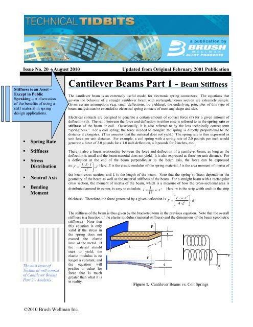
The cantilever beam is an extremely useful model for electronic spring connectors. The equations that<br />
govern the behavior of a straight cantilever beam with rectangular cross section are extremely simple.<br />
Given certain assumptions (e.g. small deflections, no yielding), the underlying principles of this type of<br />
beam analysis can be extended to electrical spring contacts of most any shape and size.<br />
Electrical contacts are designed to generate a certain amount of contact force (F) for a given amount of<br />
deflection (d). The ratio between the force and deflection in either case is referred to as the spring rate or<br />
stiffness of the beam or coil. Occasionally, it is also referred to by the less technically correct term<br />
“springiness.” For a coil spring, the force needed to elongate the spring is directly proportional to the<br />
distance it elongates. (This assumes that the material does not yield.) The spring rate is then expressed as<br />
unit force per unit distance. For example, a coil spring with a spring rate of 2.0 pounds per inch would<br />
generate a force of 2.0 pounds for a 1.0 inch deflection, 4.0 pounds for 2 inches, etc.<br />
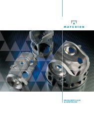
There is also a linear relationship between the force and deflection of a cantilever beam, as long as the<br />
deflection is small and the beam material does not yield. It is also expressed as force per unit distance. For<br />
a deflection at the end of the beam perpendicular to the beam axis, the force can be expressed<br />
as: 3 E I <br />
F d<br />
Here, E is the elastic modulus of the spring material, I is the area moment of inertia of<br />
3<br />
L <br />
<br />
the beam cross section, and L is the length of the beam. Note that the spring stiffness depends on the<br />
geometry of the beam as well as the material stiffness of the beam. For a straight beam with a rectangular<br />
cross section, the moment of inertia of the beam, which is a measure of how the cross-sectional area is<br />
distributed around its center, is easy to calculate. 1 3<br />
I w t Here, w is the strip width and t is the strip<br />
12<br />
3<br />
thickness. Therefore, the force generated by a given deflection is E w<br />
t <br />
F d<br />
.<br />
3<br />
4 L <br />
The stiffness of the beam is thus given by the bracketed term in the previous equation. Note that the overall<br />
stiffness is a function of the elastic modulus (material stiffness) and the dimensions of the beam (geometric<br />
stiffness.) Note that<br />
this equation is only<br />
valid if the stress in<br />
F<br />
the spring does not<br />
t<br />
exceed the elastic<br />
limit of the metal. If<br />
the material should<br />
L<br />
w<br />
start to yield, the<br />
elastic modulus is no<br />
longer a constant, and<br />
F<br />
F<br />
the equation will<br />
predict a value for<br />
force that is much<br />
greater than what it is<br />
d d<br />
in reality.<br />
Figure 1. <strong>Cantilever</strong> <strong><strong>Beam</strong>s</strong> vs. Coil Springs
<strong>Cantilever</strong> <strong><strong>Beam</strong>s</strong> <strong>Part</strong> 1 – <strong>Beam</strong> <strong>Stiffness</strong> (continued)<br />
The next step would be to solve for the stress distribution in the beam generated by the given<br />
deflection. In a coil spring, the stress is distributed evenly along the length of the coil. However, in a<br />
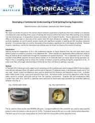
cantilever beam under a bending load, the stress is different at every point in the beam. When a beam is<br />
bent downward, the top surface of the beam elongates and is in tension. The bottom surface becomes<br />
compressed. Somewhere near the center of the beam, there is a plane that neither elongates nor<br />
compresses and thus is under no stress. This is known as the neutral axis. The stress will increase from<br />
zero at the neutral axis to a maximum value at the upper and lower surfaces, as shown in Figure 2.<br />
The stress will vary along the length of the beam, as well as through the thickness. The stress at any<br />
point depends on the bending moment (torque) present at that point. The bending moment (M) at any<br />
point in the beam is equal to the force applied multiplied by the distance from that point to the point of<br />
application. It is therefore zero at the free end of the beam, and maximum at the fixed end. This means<br />
that there is no stress at the free end of the beam, and a maximum stress at the fixed end. The equation<br />
for the stress at any point in the beam is as follows: M y F x<br />
Stress y . Here, F is the force<br />
I I<br />
applied, x is the distance from the point of force application, I is the moment of inertia, and y is the<br />
distance from the neutral axis. Since the maximum stress will occur at the upper and lower surfaces at<br />
the fixed end, ymax and xMax L . Therefore, the maximum stress can be expressed as<br />
t<br />
2<br />
F L t<br />
Max . When the moment of inertia is and the force equation is inserted, the stress equation<br />
I 2<br />
reduces to: 3<br />
E t<br />
Max d Once again, if the material begins to yield, then the above equation is no<br />
2<br />
2 L<br />
longer valid. This is because the metal’s stress-strain relationship is no longer linear beyond the elastic<br />
limit, and therefore a linear equation is no longer valid.<br />
There are some interesting consequences of these equations. Notice that the width of the beam affects<br />
the contact force but has no effect on the stress. The contact force is most influenced by thickness and<br />
length, while the stress is most influenced by length. Both the stress and force are linearly proportional<br />
to the elastic modulus and the<br />
deflection. It becomes much<br />
easier to design a contact<br />
d L<br />
spring when the relationships<br />
among force, stress,<br />
geometry, and material are<br />
t<br />
2 Neutral<br />
kept in mind. Next month’s<br />
edition of Technical Tidbits<br />
t<br />
2<br />
Axis<br />
will further explore these<br />
relationships.<br />
Figure 2. <strong>Cantilever</strong> <strong>Beam</strong> Stress Distribution<br />
Written by Mike Gedeon of Brush Wellman’s Alloy Customer Technical Service Department.<br />
Mr. Gedeon’s primary focus is on electronic strip for the telecommunications and computer<br />
markets with emphasis on Finite Element Analysis (FEA) and material selection.<br />
©2010 Brush Wellman Inc.<br />
Brush Wellman Inc.<br />
6070 Parkland Blvd.<br />
Mayfield Heights, OH 44124<br />
(216) 486-4200<br />
(216) 383-4005 Fax<br />
(800) 375-4205 Technical Service<br />
Please contact your local<br />
sales representative for<br />
further information on<br />
spring rate or other<br />
questions pertaining to<br />
Brush Wellman or our<br />
products.<br />
Health and Safety<br />
Handling copper beryllium in<br />
solid form poses no special<br />
health risk. Like many<br />
industrial materials, berylliumcontaining<br />
materials may pose a<br />
health risk if recommended safe<br />
handling practices are not<br />
followed. Inhalation of airborne<br />
beryllium may cause a serious<br />
lung disorder in susceptible<br />
individuals. The Occupational<br />
Safety and Health<br />
Administration (OSHA) has set<br />
mandatory limits on<br />
occupational respiratory<br />
exposures. Read and follow the<br />
guidance in the Material Safety<br />
Data Sheet (MSDS) before<br />
working with this material. For<br />
additional information on safe<br />
handling practices or technical<br />
data on copper beryllium,<br />
contact Brush Wellman Inc.