Lisø PhD Dissertation Manuscript - NTNU
Lisø PhD Dissertation Manuscript - NTNU
Lisø PhD Dissertation Manuscript - NTNU

Create successful ePaper yourself
Turn your PDF publications into a flip-book with our unique Google optimized e-Paper software.
LisÖ et al.<br />
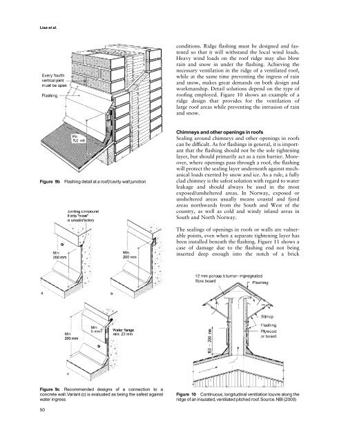
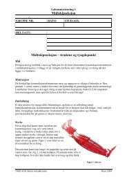
Figure 9b Flashing detail at a roof/cavity wall junction<br />
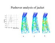
Figure 9c Recommended designs of a connection to a<br />
concrete wall.Variant (c) is evaluated as being the safest against<br />
water ingress<br />
50<br />
conditions. Ridge flashing must be designed and fastened<br />
so that it will withstand the local wind loads.<br />
Heavy wind loads on the roof ridge may also blow<br />
rain and snow in under the flashing. Achieving the<br />
necessary ventilation in the ridge of a ventilated roof,<br />
while at the same time preventing the ingress of rain<br />
and snow, makes great demands on both design and<br />
workmanship. Detail solutions depend on the type of<br />
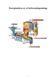
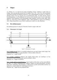
roofing employed. Figure 10 shows an example of a<br />
ridge design that provides for the ventilation of<br />
large roof areas while preventing the intrusion of rain<br />
and snow.<br />
Chimneys and other openings in roofs<br />
Sealing around chimneys and other openings in roofs<br />
can be difficult. As for flashings in general, it is important<br />
that the flashing should not be the sole tightening<br />
layer, but should primarily act as a rain barrier. Moreover,<br />
where openings pass through a roof, the flashing<br />
will protect the sealing layer underneath against mechanical<br />
loads exerted by snow and ice. As a rule, a fully<br />
clad chimney is the safest solution with regard to water<br />
leakage and should always be used in the most<br />
exposed/unsheltered areas. In Norway, exposed or<br />
unsheltered areas usually means coastal and fjord<br />
areas northwards from the South and West of the<br />
country, as well as cold and windy inland areas in<br />
South and North Norway.<br />
The sealings of openings in roofs or walls are vulnerable<br />
points, even when a separate tightening layer has<br />
been installed beneath the flashing. Figure 11 shows a<br />
case of damage due to the flashing end not being<br />
inserted deep enough into the notch of a brick<br />
Figure 10 Continuous, longitudinal ventilation louvre along the<br />
ridge of an insulated, ventilated pitched roof. Source. NBI (2000)


![Diagnosis and FTC by Prof. Blanke [pdf] - NTNU](https://img.yumpu.com/12483948/1/190x245/diagnosis-and-ftc-by-prof-blanke-pdf-ntnu.jpg?quality=85)