Lisø PhD Dissertation Manuscript - NTNU
Lisø PhD Dissertation Manuscript - NTNU
Lisø PhD Dissertation Manuscript - NTNU

You also want an ePaper? Increase the reach of your titles
YUMPU automatically turns print PDFs into web optimized ePapers that Google loves.
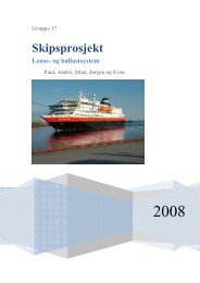
Figure 7 Example showing the recommended construction of<br />
welted parapet £ashing<br />
the flashing (on the facade side) resulting in leakage<br />
behind the wind barrier. A recommended solution is<br />
shown in Figure 7. Fastening at the inward edge of<br />
the parapet must be positioned a minimum 150 mm<br />
above the roofing material in order to prevent<br />
leakage due to static water on the roof. This in turn<br />
necessitates a parapet that is not too low.<br />
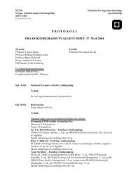
When the turndown along the facade is finished off<br />
against the wall waist, rain striking the parapet is led<br />
directly in towards the facade. Depending on the<br />
facade material, this moistening can lead to staining<br />
and frost damage (Figure 8). Norwegian Standard<br />
3420 stipulates finishing off a minimum 20 mm away<br />
from the wall waist. Among other factors, the necessary<br />
distance from wall waist depends on the height,<br />
form and location of the building.<br />
The parapet should always have a minimum 1:5 slope<br />
inwards towards the roof surface. An inwards incline<br />
reduces the danger of ice and/or snow sliding off the<br />
parapet. In addition, the slope is an important safeguard<br />
against static water, snow and/or ice and<br />
thereby water pressure on joints in the parapet flashing.<br />
High-performance weather-protective £ashings<br />
Figure 8 Finishing-off of the parapet £ashing against the<br />
wall face has led to wetting/moistening of the facade with<br />
consequent organic growth. Source: Norwegian Building<br />
Research Institute,Oslo<br />
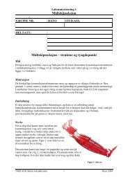
Wall £ashing details<br />
The junction between the roof and adjacent, upper<br />
outer wall is a vulnerable point. For wood frame<br />
walls, the transition must be designed by finishing<br />
the roofing underneath the wind-barrier layer<br />
within the wall (Figure 9a). Leaks can easily arise<br />
whenever the wind-barrier/roofing material overlap is<br />
missing, even when the flashing is installed as a rain<br />
shield. The most frequent cases of registered damage<br />
are for masonry and concrete walls. A typical fault is<br />
flashing not being inserted in the mortar joint<br />
(notch), or where the insertion joint has become so<br />
jagged and uneven that water can run in behind the<br />
flashing. In the case of cavity walls, one must always<br />
expect water penetration through the external face of<br />
the wall. Drainage water must therefore be drained<br />
away as shown in Figure 9b. Connection of flashing<br />
to concrete walls is shown in Figure 9c.<br />
Ridge and bevel ¢nishing<br />
The type of ridge flashing should be selected according<br />
to the type of roofing material and the local climatic<br />
Figure 9a Recommended design of roo¢ng against a wood<br />
frame wall<br />
49


![Diagnosis and FTC by Prof. Blanke [pdf] - NTNU](https://img.yumpu.com/12483948/1/190x245/diagnosis-and-ftc-by-prof-blanke-pdf-ntnu.jpg?quality=85)