ZHF Centrifugal Discharge Filter System - Pall Corporation
ZHF Centrifugal Discharge Filter System - Pall Corporation
ZHF Centrifugal Discharge Filter System - Pall Corporation

Create successful ePaper yourself
Turn your PDF publications into a flip-book with our unique Google optimized e-Paper software.
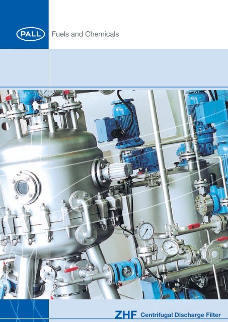
<strong>ZHF</strong><br />
<strong>Centrifugal</strong> <strong>Discharge</strong> <strong>Filter</strong>
<strong>ZHF</strong> <strong>Centrifugal</strong> <strong>Discharge</strong> <strong>Filter</strong><br />
GENERAL<br />
Due to increased quality demands on the manufacture of<br />
many products process filtration gains importance. Additionally,<br />
workers’ safety, minimizing and eliminating substance<br />
exposure while maintaining a simple and familiar filtration<br />
operation necessitate the use of totally enclosed filters with<br />
a broad range of features. Hence, the choice and proper<br />
selection of a filtration system is essential for meeting<br />
increased stringent requirements. <strong>Pall</strong> SeitzSchenk <strong>Filter</strong><br />
<strong>System</strong>s is dedicated to the design and construction of<br />
solid-liquid separation equipment in many branches of the<br />
Chemical industry. Our specialists will be pleased to provide<br />
you with the know-how and assist you in finding the optimum<br />
solution for your filtration needs.<br />
<strong>Centrifugal</strong> <strong>Discharge</strong> <strong>Filter</strong> <strong>ZHF</strong> Description of <strong>Filter</strong><br />
• The <strong>Pall</strong> SeitzSchenk <strong>Centrifugal</strong> <strong>Discharge</strong> <strong>Filter</strong> Type<br />
<strong>ZHF</strong> consists mainly of a pressure vessel with a hollow<br />
center shaft around which series of round filter elements<br />
are vertically stacked at specific, but variable spacing.<br />
• The filter stack, consisting of both the hollow shaft and<br />
the elements, is installed in the vessel, so that it can<br />
freely rotate. To clean the filter, the whole stack is spun<br />
by means of a drive system.<br />
• The hollow shaft that serves as a filtrate discharge manifold<br />
is connected to an external drive motor permitting the<br />
removal of cake by centrifugal action.<br />
• The filter elements are covered, depending on requirement,<br />
with woven wire, textile material, sintered metal or<br />
perforated plates. For cake stability, the elements are<br />
covered only on the upper side.<br />
• The pressure vessel can be designed and built to meet<br />
most international and local codes (i.e. ASME, AD, etc.).<br />
Available materials of construction are Carbon Steel,<br />
rubberized or glass lined steel, Stainless Steel,<br />
Hastelloy, Titanium, etc. A broad range of pressure and<br />
temperature design conditions are available.<br />
FILTER OPERATION<br />
During filtration the filter vessel is fed under pressure; the<br />
filtrate passes through the plates and out through the shaft.<br />
The filter cake forms on the upper side of the filter elements.<br />
After filtration, the remaining feed in the vessel is either<br />
drained or filtered via the scavenge system. The cake may<br />
then be washed or dried by an appropriate heated gas.<br />
Spinning the entire stack at moderate speeds generates a<br />
centrifugal force that discharges the cake. The cake can be<br />
discharged in slurry or dry form.<br />
The operating advantages of the SeitzSchenk <strong>Centrifugal</strong><br />
<strong>Discharge</strong> <strong>Filter</strong> is the use of horizontal filter elements and<br />
the ability of automatic cake discharge without having to<br />
open the filter.
MAIN FEATURES AND ADVANTAGES<br />
• Bottom-drive<br />
- Simple installation, low headroom, and low center of<br />
gravity.<br />
- Each dynamic seal can be checked and replaced, if<br />
necessary, without disturbing the filter stack.<br />
- Removal of filter element stack is achieved without<br />
disturbing the rotational drive mechanism.<br />
• Scavenge filtration<br />
An independent scavenge filtration system is provided<br />
with a separate and independent filtrate outlet. This system<br />
minimizes the remaining feed material in the filter after<br />
completion of the batch.<br />
• Totally enclosed system:<br />
- Provides safe operation with biohazardous substances.<br />
(i.e. production and harvest of therapeutical proteins<br />
by CHO cells)<br />
- safe operation with toxic, explosive or other<br />
hazardous substances<br />
• Automatic discharge of filter cake<br />
- No manual cleaning operation<br />
- Brief «downtime»<br />
- Easy automation<br />
- Cake discharge by centrifugation<br />
- Dust-free discharge under clean room conditions<br />
• Horizontal filter elements<br />
- Optimal filter cake distribution, unaffected by pressure<br />
fluctuation or power (pump) failure.<br />
- Effective cake washing and drying are possible.<br />
- Spacers support the filter elements at the periphery.<br />
- This guarantees equal spacing.<br />
- Also cake-bridging impact is minimized.<br />
- The filter element has a central welded hub. Only<br />
ONE seal is necessary per element.<br />
- The filter element stack is preloaded until metal to<br />
metal contact is achieved at the periphery and center<br />
hub, thus attaining an exceptionally strong stack with<br />
no floating members.<br />
3
<strong>ZHF</strong> <strong>Centrifugal</strong> <strong>Discharge</strong> <strong>Filter</strong><br />
20<br />
15<br />
4<br />
1<br />
19<br />
8<br />
13<br />
14<br />
12<br />
9<br />
17<br />
11<br />
10<br />
16<br />
7<br />
6<br />
2<br />
4<br />
5<br />
16<br />
18<br />
3<br />
1<br />
2<br />
3<br />
4<br />
5<br />
6<br />
7<br />
8<br />
9<br />
10<br />
11<br />
12<br />
13<br />
14<br />
15<br />
16<br />
17<br />
18<br />
19<br />
20<br />
<strong>Filter</strong> vessel with sight glass<br />
Hollow filter shaft<br />
<strong>Filter</strong> plate<br />
Scavenge plate<br />
Support ring with discharge aids<br />
Spider ring with deflector plate<br />
Thrust collar<br />
Compression flange<br />
Drive shaft with bearing housing<br />
and hydraulic motor<br />
Protector sleeve<br />
Seal arrangement (bearing housing)<br />
Seal arrangement (distribution housing)<br />
Upper bearing housing<br />
Seal flush system<br />
Pump unit for hydrostatic drive or<br />
other drives<br />
Feed inlet<br />
Filtrate outlet<br />
Scavenge filtrate outlet<br />
Heel drainage<br />
Cake discharge
<strong>ZHF</strong>-S<br />
S – vertical vessel wet cake discharge (slurry)<br />
PRECOAT FILTER<br />
<strong>ZHF</strong>-S model is primarily a precoat filter with a main function<br />
to recover the liquid phase (filtrate). The filter elements are<br />
normally pre-coated with a layer of filter aid. Depending on<br />
the nature of the feed material, further filter aid may be added<br />
to the feed using <strong>Pall</strong> SeitzSchenk mixing and dosing equipment.<br />
If the formed cake (from solids in feed suspension) is<br />
permeable enough to act as a filter aid, then precoating and<br />
dosing of body feed may be avoided. Discharging the formed<br />
cake is achieved by rotation, with simultaneous backwash,<br />
of the filter stack whereby the cake is removed as a slurry<br />
via the filter vessel through the bottom discharge outlet. The<br />
<strong>ZHF</strong>-S filter is available with up to 200 m2 of filtration area.<br />
A heel (scavenge) recovery filtration system is also available.<br />
<strong>ZHF</strong>-SR-KL AND SR-KLK<br />
SR = vertical vessel dry cake discharge<br />
KL = cylindrical vessel dished end design<br />
KLK = tapered vessel dished end design<br />
SOLIDS/CAKE RECOVERY FILTER<br />
The <strong>ZHF</strong>-SR KL and KLK filters can be used simultaneously<br />
for a precoat and/or solids recovery applications. They come<br />
equipped with an integral discharger, a mechanical system<br />
that aids in the discharge and removal of the cake. When<br />
used for solids recovery, the same procedure is used as with<br />
the <strong>ZHF</strong>-S precoat filter. Upon the completion of filtration,<br />
the cake can be washed, extracted and/or dried in-situ. The<br />
mechanical discharge device and a large solids discharge<br />
outlet enable the filter cake to be removed in a dry state (the<br />
degree being dependent on its characteristics). A special<br />
design, offering a tapered vessel (KLK-design) is available<br />
for certain applications where minimal residual heel of stick<br />
or heavy cake is desired, and to ensure trouble free cake<br />
discharge. The <strong>ZHF</strong>-SR KL and KLK filters are available with<br />
up to 200 m2 of filtration area. A scavenge recovery filtration<br />
system is also available.<br />
5
<strong>ZHF</strong> <strong>Centrifugal</strong> <strong>Discharge</strong> <strong>Filter</strong><br />
6<br />
PALL SEITZSCHENK <strong>ZHF</strong>-L<br />
L – horizontal vessel<br />
2<br />
3<br />
7<br />
① Vessel<br />
② Bearing<br />
③ Drive<br />
④ Filtrate shaft<br />
⑤ Spacer ring<br />
⑥ <strong>Filter</strong> element<br />
⑦ Drive for high pressure cleaning<br />
⑧ Cleaning jets<br />
1 8<br />
PALL SEITZSCHENK <strong>ZHF</strong>-SR-KL<br />
RESIDUE (DRY DISCHARGE) FILTER<br />
SeitzSchenk <strong>ZHF</strong>-SR-KL and KLK residue filters are used<br />
for filtrate and/or cake recovery. The filter residue can be<br />
6<br />
4<br />
5<br />
1<br />
treated (washed, extracted, dried) in-place within the filter. It<br />
is then discharged, using an integral mechanical discharge<br />
aid in a dry or paste like form.<br />
APPLICATIONS<br />
Catalyst Separation: Raney nickel, palladium, platinum,<br />
copper.<br />
Salt Separation: Polyole, Polyetherole.<br />
Resins/Waxes: alkyd resins, phenolic resin, epoxy<br />
resin, paraffines.<br />
Mineral Oils: light petrol, additives.<br />
Polymere: PE, PP, optical brighteners, plasticiser,<br />
viscose.<br />
Chlor-Alkali Industry: brine solution, mercury separation<br />
from caustic soda.
TEST UNITS<br />
<strong>Pall</strong> SeitzSchenk has different <strong>Centrifugal</strong> <strong>Discharge</strong> <strong>Filter</strong>s<br />
type <strong>ZHF</strong> available for tests at the works of the customer.<br />
The units are rent to reasonable conditions. SCHENK also<br />
AVAILABLE TEST UNITS<br />
• <strong>Filter</strong> unit <strong>ZHF</strong>-SR 2,5/1KL<br />
filtration area 1 m 2<br />
with pump<br />
with precoat tank<br />
material of construction 1.4571/1.4401<br />
design 6 bar<br />
complete with pipings and electric<br />
electric Eex d II T3<br />
offers technical support during the tests and control of the<br />
tests.<br />
• <strong>ZHF</strong>-SR 5 KL<br />
filtration area approx. 5 m2 scavenge filtration area approx. 1 m2 with drive<br />
motor Eex e II T3<br />
7
<strong>ZHF</strong> <strong>Centrifugal</strong> <strong>Discharge</strong> <strong>Filter</strong><br />
8<br />
<strong>ZHF</strong> - SUSPENDED DRIVE<br />
<strong>ZHF</strong> - FRAME-MOUNTED DRIVE
PROCESS DIAGRAM OF A SCHENK CENTRIFUGAL SELFCLEANING FILTER<br />
WITH SEMI OR FULLY AUTOMATIC CONTROL<br />
valve open or motor on<br />
automatic<br />
automation locked, valve closed<br />
manual valve<br />
remote controlled valve<br />
sightglass<br />
float switch<br />
1 fill filter - precoat<br />
2 re-cycle<br />
3 filtration<br />
4 scavenge I<br />
5 scavenge II<br />
6 drain<br />
7 drying<br />
8 pressure relief<br />
9 discharge<br />
1 2 3 4 5 6 7 8 9 10 11 12 13 14 15 M1 M2 M3 P1 P2<br />
1 fill filter - precoat o o o a o o o o o<br />
2 re-cycle o o o a o o o o o o<br />
3 filtration o o o a o o o o o<br />
4 scavenge I o x o o<br />
5 scavenge II o x o o<br />
6 drain x o o<br />
7 drying o x o o o<br />
8 pressure relief a<br />
9 discharge a o o o<br />
10 neutral a<br />
9
<strong>ZHF</strong> <strong>Centrifugal</strong> <strong>Discharge</strong> <strong>Filter</strong><br />
10<br />
* frame underdrive unit only<br />
filter-type filterelements filtervessel total weight filter- type of dimensions<br />
motor drive<br />
<strong>ZHF</strong> main filterelement with 30 mm spacing scavenge element with 30 mm spacing diameter vessel fully equipped kW mechanical height floor space<br />
empty<br />
6 bar/20°C<br />
hydraulic<br />
element filter area number filter area element filter area number filter area total vessel- vessel Ø main shipping<br />
diameter element diameter element cake volume flange Ø weight A B C D* E F<br />
volume width length<br />
mm m2 m2 mm m2 m2 m3 m3 mm mm kg kg mm mm mm mm mm mm<br />
Design A – Size 0 (Type SR 3 – element 505 mm – shaft 60/72 mm)<br />
S 2,5 /A0 600 mech.<br />
SR 2,5 KL/A0 Ø 505 0.172 13 2.2 Ø 505 0.172 2 0.35 0.07 0.22 600 655 400 650 5.5 hydro 2800 1720 1410 100 1500 1200<br />
SR 2,5 KLK/A0 600/700<br />
Design B – Size 1 (Type SR 10 – element 805 mm – shaft 76/90 mm)<br />
S 5 B1 Ø 805 0.47 10 4.7 Ø 805 0.47 2 0.94 0.17 0.35 900 960 650 1200 7.5 mech. 2875 1735 1585 160 1600 1800<br />
SR 5 KL/B1 hydraulic<br />
S 10 /B1 900 mech.<br />
SR 10 KL/B1 Ø 805 0.47 21 9.87 Ø 805 0.47 2 0.94 0.30 0.7 900 960 1050 1600 11 hydraulic 3650 2100 1830 160 1600 1800<br />
SR 10 KLK/B1 900/1000<br />
S 15 /B1 900 mech.<br />
SR 15 KL/B1 Ø 805 0.47 32 15.04 Ø 805 0.47 2 0.94 0.45 1.0 900 960 1200 2000 15 hydraulic 4450 2510 2240 160 1600 1800<br />
SR 15 KLK/B1 900/1000<br />
Design B – Size 2 (Type SR 20 – element 985 mm – shaft 76/90 mm<br />
S 20 /B2 1100 mech.<br />
SR 20 KL/B2 Ø 985 0.71 28 19.88 Ø 985 0.71 2 1.42 0.60 1.3 1100 1160 1500 2200 18.5 hydraulic 4300 2450 2140 160 1800 2000<br />
SR 20 KLK/B2 1100/1200<br />
S 25 /B2 1100 mech.<br />
SR 25 KL/B2 Ø 985 0.71 35 24.85 Ø 985 0.71 2 1.42 0.76 1.6 1100 1160 1600 2500 22 hydraulic 5150 2730 2420 160 1800 2000<br />
SR 25 KLK/B2 1100/1200<br />
S 30 /B2 1100 mech.<br />
SR 30 KL/B2 Ø 985 0.71 45 31.95 Ø 985 0.71 2 1.42 0.97 1.8 1100 1160 1900 3100 30 hydraulic 5650 3260 2900 160 1800 2300<br />
SR 30 KLK/B2 1100/1200<br />
Design C – Size 3 (Type SR 40 – element 1200 mm – shaft 115/125 mm)<br />
S 30/32 /C3 1350 mech.<br />
SR 30/32 KL/C3 Ø 1200 1.075 28 30.1 Ø 985 0.7 3 2.1 0.9 1.8 1350 1420 1400 4700 37 hydraulic 5220 2850 2395 310 2300 3000<br />
SR 30/32 KLK/C3 1350/1450 4960 2640 2185 260<br />
S 40/43 /C3 1350 mech.<br />
SR 40/43 KL/C3 Ø 1200 1.075 37 39.77 Ø 985 0.7 4 2.8 1.2 2.2 1350 1420 1560 5050 37 hydraulic 5980 3230 2775 310 2300 3000<br />
SR 40/43 KLK/C3 1350/1450 5720 3020 2565 260<br />
S 50/53 KLK/C3 Ø 1200 1.075 47 50.52 Ø 985 0.7 4 2.8 1.5 2.9 1350/1450 1420 1850 5350 45 mech. 6680 3580 3125 310 2300 3000<br />
SR 50/53 KLK/C3 37 hydraulic 6420 3370 2915 260<br />
S 60/63 KL/C3 Ø 1200 1.075 55 59.12 Ø 985 0.7 5 3.5 1.8 3.6 1350/1450 1420 1950 5700 45 mech. 7380 3930 3475 310 2300 3000<br />
SR 60/63 KLK/C3 37 hydraulic 7120 3720 3265 260
* frame underdrive unit only<br />
filter-type filterelements filtervessel total weight filter- type of dimensions<br />
motor drive<br />
<strong>ZHF</strong> main filterelement with 30 mm spacing scavenge element with 30 mm spacing diameter vessel fully equipped kW mechanical height floor space<br />
empty<br />
6 bar/20°C<br />
hydraulic<br />
element filter area number filter area element filter area number filter area total vessel- vessel Ø main shipping<br />
diameter element diameter element cake volume flange Ø weight A B C D* E F<br />
volume width length<br />
mm m2 m2 mm m2 m2 m3 m3 mm mm kg kg mm mm mm mm mm mm<br />
Design D – Size 3 (Type SR 80 – element 1200 mm – shaft 150/170 mm)<br />
S 80/69 KLK/D3 Ø 1200 1.06 61 64.66 Ø 985 0.685 6 4.2 1.9 4.0 1350/1450 1420 2400 6900 55 mech. 8240 4540 4080 310 2800 3200<br />
SR 80/69 KLK/D3 45 hydraulic 7960 4310 3850 260<br />
S 90/81 KLK/D3 Ø 1200 1.06 72 76.32 Ø 985 0.685 6 4.2 2.3 4.4 1350/1450 1420 2600 7400 55 mech. 9040 4940 4480 310 2800 3200<br />
SR 90/81 KLK/D3 45 hydraulic 8760 4710 4250 260<br />
S 100/91 KLK/D3 Ø 1200 1.06 81 85.86 Ø 985 0.685 7 4.9 2.6 5.1 1350/1450 1420 2800 7950 55 mech. 9840 5340 4880 310 2800 3200<br />
SR 100/91 KLK/D3 45 hydraulic 9560 5110 4650 260<br />
Design D – Size 4 (Type SR 130 – element 1500 mm – shaft 150/170 mm)<br />
S 90/86 KLK/D4 Ø 1500 1.65 48 79.2 Ø 1200 1.06 6 6.36 2.4 5.75 1750/1900 1820 3250 9000 55 hydraulic 7260 4010 3550 260 2800 3200<br />
SR 90/86 KLK/D4<br />
S 110/104 KLK/D4 Ø 1500 1.65 59 97.35 Ø 1200 1.06 6 6.36 2.9 6.7 1750/1900 1820 3500 9600 55 hydraulic 8060 4410 3950 260 2800 3200<br />
SR 110/104 KLK/D4<br />
S 130/120 KLK/D4 Ø 1500 1.65 69 113.85 Ø 1200 1.06 6 6.36 3.4 7.6 1750/1900 1820 3750 10 200 55 hydraulic 8860 4810 4350 260 2800 3200<br />
SR 130/120 KLK/D4<br />
Design E – Size 4 (Type SR 100 – element 1500 mm – shaft 205/230 mm)<br />
S 150/130 KLK/E4 Ø 1500 1.60 77 123.2 Ø 1200 1.03 7 7.21 3.7 8.75 1750/1900 1820 4200 11700 75 hydraulic 9910 5500 4850 260 3000 3800<br />
SR 150/130 KLK/E4<br />
S 170/151 KLK/E4 Ø 1500 1.60 90 144.0 Ø 1200 1.03 7 7.21 4.3 9.80 1750/1900 1820 4400 12 400 75 hydraulic 10 910 6000 5350 260 3000 3800<br />
SR 170/151 KLK/E4<br />
Nozzle connections<br />
part 1 2 3 4 5 6 7 8 9 10 11 12 13 14 15 16<br />
feed filtrate scavenge heel volume vent comp. press. spare gland sight steam condensate savety valve cake discharge<br />
type filtrate return air gauge irrigation glass inlet outlet<br />
top bottom inlet* outlet* connections S SR-KL<br />
SR-KLK<br />
25/A0 50 50 50 20 50 25 25 50 50 10 150 25 25 40 50 100/PN10 150/PN10<br />
5/B1 – 10/B1 50 50 50 25 50 50 25 50 50 10 150 25 25 40 50 125/PN10 300/PN10<br />
15/B1 50 50 50 25 50 50 25 50 50 10 150 25 25 50 80 125/PN10 300/PN10<br />
20/B2 – 25/B2 65 65 65 25 50 50 25 50 50 10 150 25 25 50 80 150/PN10 350/PN10<br />
30/C3 – 60/C3 80 80 80 25 50 50 50 50 50 15 150 25 25 50 80 150/PN10 400/PN10<br />
80/D3 – 100/D3 100 100 125 50 80 80 80 50 80 15 150 25 25 80 100 200/PN10 400/PN10<br />
90/D4 – 130/D4 125 125 150 50 100 80 80 50 100 15 150 50 50 80 100 350/PN10 500/PN10<br />
150/E4 – 170/E4 150 150 175 50 125 100 100 50 125 15 150 50 50 100 150 350/PN10 500/PN10<br />
* size depending on product<br />
to DIN 2633/PN16Trubaustrag<br />
cake discharge to DIN 2633/PN10<br />
11
Fuels and Chemicals<br />
<strong>Pall</strong> GmbH SeitzSchenk<br />
Planiger Strasse 137<br />
55543 Bad Kreuznach/Germany<br />
+49.(0)671.88220 phone<br />
+49.(0)671.8822200 fax<br />
fuels.chemicals.de@pall.com email<br />
Besuchen Sie uns im Internet unter www.pall.de<br />
Wir sind vertreten in folgenden Ländern:<br />
Argentina, Australia, Austria, Belgium, Brazil, Canada, China, France, Germany, India,<br />
Indonesia, Ireland, Italy, Japan, Korea, Malaysia, Mexico, the Netherlands, New Zealand,<br />
Norway, Poland, Puerto Rico, Russia, Singapore, South Africa, Spain, Sweden,<br />
Switzerland, Taiwan, Thailand, United Kingdom, United States, and Venezuela.<br />
Distributors are located in all major industrial areas of the world.<br />
© Copyright 2002, <strong>Pall</strong> <strong>Corporation</strong>. <strong>Pall</strong>, , are trademarks of <strong>Pall</strong> <strong>Corporation</strong>. ® Indicates a <strong>Pall</strong><br />
trademark registered in the USA. is a service mark of <strong>Pall</strong> <strong>Corporation</strong>.<br />
*Select-A-FAX is a registered trademark of CyberData, Inc.<br />
Reorder Code. PFC-P102 engl. 1 09/04 O