Centrifugal Fans AT belt driven - Nicotra Gebhardt
Centrifugal Fans AT belt driven - Nicotra Gebhardt
Centrifugal Fans AT belt driven - Nicotra Gebhardt

You also want an ePaper? Increase the reach of your titles
YUMPU automatically turns print PDFs into web optimized ePapers that Google loves.
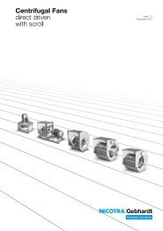
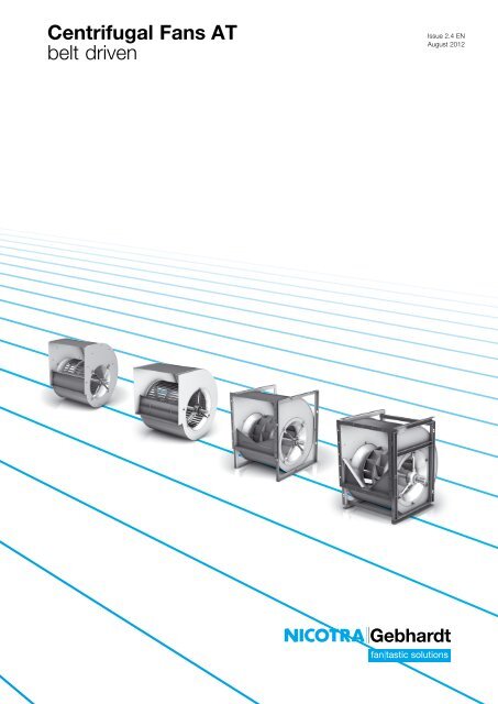
<strong>Centrifugal</strong> <strong>Fans</strong> <strong>AT</strong><br />
<strong>belt</strong> <strong>driven</strong><br />
Issue 2.4 EN<br />
August 2012<br />
1
AMCA<br />
<strong>Nicotra</strong> <strong>Gebhardt</strong> stands for:<br />
A Maximised flexibility and minimised<br />
design effort for customers,<br />
because all radial fan<br />
casings have identical dimensions<br />
– no matter what kind of<br />
impeller geometry<br />
<strong>Nicotra</strong> <strong>Gebhardt</strong> S.p.A. (Italy) certifies that<br />
ADH-E fans of the E0, E2, E4, E6 and E7 versions,<br />
from sizes 0160 to 0560,<br />
RDH-E fans of the E0, E2, E4, E6 and E7 versions,<br />
from sizes 0180 to 0560,<br />
ADH and RDH fans of the L, R, K, K1 and K2 versions,<br />
from sizes 0630 to 1000,<br />
<strong>AT</strong> fans of the S, SC, C and TIC versions,<br />
from sizes 7/7 to 30/28,<br />
shown herein are licensed to bear the AMCA Seal.<br />
<strong>Nicotra</strong> <strong>Gebhardt</strong> GmbH (Germany) certifies that<br />
RZR fans of the 11, 12, 15 versions, from sizes 0355 to 1000,<br />
shown herein are licensed to bear the AMCA Seal.<br />
The ratings shown are based on tests and procedures performed<br />
in accordance with AMCA Publication 211 and comply<br />
with the requirements of the AMCA Certified Ratings Program.<br />
Air performance with Installation Type “A” (“with free outlet”),<br />
and that of the twin fan versions G2L, G2R, G2K, G2K2,<br />
G2E0, G2E2, G2E4, G2E7, SC2, G2C and G2C-C2, and that<br />
of the triple fan versions G3C and G3C-C2 in any installation<br />
type is not AMCA licensed.<br />
A Top product quality and shorter<br />
delivery times – thanks to<br />
state-of-the-art production<br />
technology<br />
A Energy efficiency through comprehensive<br />
system know-how<br />
I
II<br />
The <strong>Nicotra</strong> <strong>Gebhardt</strong> portfolio<br />
A strong provider for many optimal<br />
solutions<br />
When it comes to radial fans, we are the first people you should<br />
talk to. From <strong>belt</strong>-<strong>driven</strong> radial fans to plugfans, it’s all there in our<br />
product portfolio. We offer the largest, most comprehensive range of<br />
products in this area – and of course the matching services.<br />
ADH-E / ADH <strong>AT</strong> RDH-E / RDH RZR<br />
double-inlet<br />
forward-curved<br />
impeller geometry<br />
When everything fits<br />
double-inlet<br />
inch diameters<br />
forward-curved impeller<br />
geometry<br />
To us, perfection in our product portfolio means that all product<br />
series in the area of encased radial fans are attuned to one another<br />
and are 100% compatible in their dimensions.<br />
How did we do it?<br />
The compact base frame from <strong>Nicotra</strong> <strong>Gebhardt</strong><br />
double-inlet<br />
backward-curved<br />
impeller geometry<br />
double-inlet<br />
hollow aerofoil<br />
impeller geometry<br />
By using an identical design for the connection dimensions of every<br />
fan size in our newly developed series ADH-E and RDH-E and<br />
carefully coordinating our options and accessories.<br />
In this way, we have standardised and harmonised our product<br />
portfolio in all relevant areas.<br />
Well designed, easy to install,<br />
economical<br />
A system that saves space, time, and money – in an air handling<br />
unit or any other application: our compact base frame offers<br />
decisive advantages:<br />
A The frame lengths have been optimised and<br />
adjusted for the casing position and motor<br />
installation height to achieve the smallest possible overall height<br />
and length<br />
A Exact, optimised coordination of all components, all the way<br />
through to installation, adjustment and testing<br />
A Suitable for all fans of the series ADH-E0, RDH-E0 and RZR-11 up<br />
to size 0500
2<br />
proSELECTA II<br />
proSELECTA II is a technical selection program that allows you to<br />
configure your own individually designed fan. It provides you with<br />
the opportunity to choose from the entire range of fan types and<br />
their associated options.<br />
Simple and reliable selection<br />
The result from proSELECTA II is the provision of all the<br />
technical data for your fan, including sound level data, dimension<br />
specifications and accessories. Apart from that, as a registered<br />
user, your purchase prices are provided. Additionally fully<br />
dimensioned drawings in DXF format are available, which can be<br />
downloaded and transferred straight into your CAD system.<br />
So that you can be sure<br />
Models and options that are technically not permissible, are<br />
automatically excluded in proSELECTA II. So there is no chance<br />
that you will configure a “wrong” device option.<br />
What else is important to you<br />
During the fan selection process, you can choose any of the<br />
standardised <strong>AT</strong>EX options.<br />
Free registration and many advantages<br />
You can register as a proSELECTA II user with us, which enables us<br />
to offer you faster order processing. What this means for you is:<br />
A The complete configuration of your fan with its associated system<br />
accessories and <strong>belt</strong> drive layout.<br />
A The possibility to produce fans that operate via a frequency<br />
inverter.<br />
A The option of saving your own fan configuration on our server.<br />
A The opportunity to modify your saved configuration, even over the<br />
phone to your <strong>Nicotra</strong> <strong>Gebhardt</strong> representative.
High performance centrifugal fan ADH<br />
double inlet for <strong>belt</strong> drive<br />
impeller with forward curved blades of galvanised<br />
sheet steel<br />
High performance centrifugal fan <strong>AT</strong><br />
double inlet for <strong>belt</strong> drive<br />
impeller with forward curved blades of galvanised<br />
sheet steel<br />
High performance centrifugal fan RDH<br />
double inlet for <strong>belt</strong> drive<br />
centrifugal impeller with backward inclined blades<br />
High performance centrifugal fan RZR<br />
double inlet for <strong>belt</strong> drive<br />
high performance impeller with backward curved<br />
hollow section true aerofoil blades<br />
Fittings / Accessories<br />
Description<br />
A Volume<br />
up to 300,000 m³/h<br />
A Pressure<br />
up to 2,200 Pa<br />
A Volume<br />
up to 65,000 m³/h<br />
A Pressure<br />
up to 2,500 Pa<br />
A Volume<br />
up to 290,000 m³/h<br />
A Pressure<br />
up to 3,500 Pa<br />
A Volume<br />
up to 300,000 m³/h<br />
A Pressure<br />
up to 3,500 Pa<br />
A complete system accessories<br />
A miscellaneous fittings<br />
A technical description<br />
A operating limits<br />
3<br />
ADH<br />
<strong>AT</strong><br />
RDH<br />
RZR<br />
Accessories<br />
Description
The <strong>Nicotra</strong> <strong>Gebhardt</strong> best-sellers, simply!<br />
50<br />
The series <strong>AT</strong><br />
<strong>Fans</strong> of <strong>AT</strong> series don’t need any presentation: they have been one of the main<br />
strengths in the <strong>Nicotra</strong> <strong>Gebhardt</strong> product range for over 35 years and have long<br />
been appreciated for their unequalled combination of compactness, efficiency, quietness<br />
of operation and versatility, at an extremely affordable price.<br />
News<br />
How we can improve a perfect fan?<br />
We tried, anyway: we developed a new seaming process, to join the back plate to the<br />
side plates with a fully automated process.<br />
The result is a new scroll without welding and whatever can become rusty, also providing<br />
a better structural strength to vibrations.<br />
And, since we like to be coherent, we even deleted welding of the side frames, which<br />
are now screwed to scrolls, and from spars, now riveted.<br />
Searching for excellence<br />
Who have say that a product with a nice price cannot be a nice product?<br />
The success of the <strong>AT</strong> series confirm is the real proof: the bearings have been selected<br />
to achieve, at maximum load and with suitable pulleys, a bearing life of 40.000<br />
hours, a number that can be considerably greater in more common load conditions.<br />
Top quality materials, innovative technology of scroll and impeller manufacturing and<br />
assembly, high efficiency, options and accessories, everything has been chosen to<br />
provide a long operating life time, with the maximum quietness and safety.<br />
Complete range<br />
Aren’t you convinced?<br />
Have a look to the range of the <strong>AT</strong> fans, you immediately realize that, as far as we<br />
can, we’re doing our best to try and meet all your requirements.<br />
We have single, twin and triple fans, with or without side frames, with one, two or<br />
three bearings for light or heavy duty, we have versions with hollow shafts, when there<br />
is the need of reducing the weight without reducing the fan performance, and also<br />
spark-proof versions.<br />
Do you still think that we don’t have the right fan for you?
Product overview<br />
range <strong>AT</strong><br />
This kind of fans are specially conceived for mechanical ventilation, at temperatures from -20 °C to +40 °C on S, SC, G2L and SC2 models, or<br />
up to 100 °C on AR, TIC, G2C, G2C-C2, G3C, G3C-C2 models.<br />
Air performance and sound data have been obtained in a laboratory registered by AMCA for AMCA 210/99 air performance testing and they are<br />
within the tolerances allowed by the DIN 24166 standard for Class 2.<br />
Single, twin and triple fans<br />
A Impeller size (diameter/width) from 7/7 to 30/28<br />
A Lap-jointed scroll of galvanized steel assembled with roller-lock<br />
seaming (sizes up to 18/18) or with Pittsburgh lock seam (for sizes<br />
larger than 18/18)<br />
A Straight cut off plate at fan outlet<br />
A Impeller with forward curved blades of galvanized steel, optimized for<br />
the best efficiency and quietness<br />
A Galvanized steel shaft<br />
<strong>AT</strong> S<br />
<strong>AT</strong> SC<br />
<strong>AT</strong> AR<br />
<strong>AT</strong> TIC<br />
<strong>AT</strong> G2L<br />
<strong>AT</strong> SC2<br />
<strong>AT</strong> G2C<br />
<strong>AT</strong> G2C-C2<br />
Single, twin and triple fans.<br />
A Airflow up to 180.000 m³/h<br />
A Total pressure up to 1.400 Pa<br />
The variety<br />
We have the right fan for all your applications!<br />
Depending on the fan size, five single fan versions, four twin fan versions and two triple fan versions are available in the <strong>AT</strong> range.<br />
Version<br />
Version<br />
Description<br />
Light construction, without feet and outlet flange.Light-duty bearing and pressed steel bearing<br />
supporting brackets.<br />
With rectangular side frame and without outlet flange.Light-duty bearing and pressed steel<br />
bearing supporting brackets. C version has also three steel bars with the ends welded to three<br />
corners of both the side frames.<br />
With heavy duty reinforced side frames, joined by three steel bars in three corners and without<br />
outlet flange. Medium duty bearing inside lubricatable, cast iron pillow block, mounted on a<br />
robust cross-bar.<br />
With heavy duty reinforced side frames, joined by four steel bars in four corners and without<br />
outlet flange. Medium-heavy duty bearing inside lubricatable, cast iron pillow block, mounted<br />
on a robust cross-bar.<br />
Description<br />
Two S-version single fans joined together by three U-section spars. The two impellers are<br />
mounted on a common shaft, supported by three bearings.<br />
Two SC-version single fans joined together by three L-section spars. The two impellers are<br />
mounted on a common shaft, supported by three bearings.<br />
Two single fans mounted side-by-side inside a common supporting frame of three L-section<br />
spars. The two impellers are mounted on a common shaft, supported at the ends by just two<br />
bearings.Use of hollow shafts on the larger sizes.<br />
Mechanically similar to G2C fans but stronger, thanks to the use of hollow shafts with larger<br />
diameter (45 mm) journals and plummer blocks with heavy-duty bearings.<br />
Figure<br />
Figure<br />
51
<strong>AT</strong> 7/7<br />
Technical Data<br />
Impeller Data Impeller Data<br />
Impeller diameter<br />
Number of blades<br />
Dr z<br />
200<br />
46<br />
mm Impeller weight<br />
Density of media<br />
Moment of Inertia<br />
J 0.009 kgm² Tolerance class (DIN 24166)<br />
Performance Curves<br />
Please note coloured area!<br />
N all types suitable<br />
N do not use in this area<br />
2000<br />
p F<br />
52<br />
Pa<br />
1500<br />
1000<br />
800<br />
600<br />
500<br />
400<br />
300<br />
200<br />
150<br />
100<br />
80<br />
60<br />
50<br />
40<br />
P r<br />
0.01<br />
30<br />
150 200<br />
0.02<br />
qV 0.06 0.08<br />
0.9 1<br />
v2 1.4<br />
0.6 0.8 1<br />
pd2 ∆L Wrel4 (A)<br />
Duty<br />
point<br />
Speed<br />
1/min<br />
dB<br />
SX 2200 3<br />
SX 1400 3<br />
SX 800 2<br />
qV opt 2200 3<br />
qV opt 1400 2<br />
qV opt 800 2<br />
DX 2200 3<br />
DX 1400 2<br />
DX 800 2<br />
0.04<br />
300<br />
0.06<br />
2<br />
SX<br />
0.1<br />
2<br />
0.12<br />
400<br />
0.18<br />
0.25<br />
55<br />
500<br />
Belt Driven <strong>Centrifugal</strong> <strong>Fans</strong> / <strong>AT</strong> / Technical Data<br />
Performance certified is for installation type B - free inlet, ducted outlet.<br />
Power rating (kW) does not include transmission losses.<br />
Performance ratings do not include the effects of appurtenances (accessories).<br />
0.37<br />
600<br />
0.55<br />
kW<br />
0.75<br />
0.2<br />
60<br />
Normal operation area<br />
800<br />
40%<br />
1.1<br />
48<br />
m 1.25 kg<br />
r 1 1.2 kg/m³<br />
2<br />
3 4 5 6 7 8 9 10 14 20 30<br />
3 4 6 8 10 20 40 60 80 100 200 400 600<br />
Relative sound power level for inlet side L Wrel7 at octave<br />
centre frequencies f c<br />
63 125 250 500 1000 2000 4000 8000 Hz<br />
-2 -7 0 -8 -8 -6 -7 -12 dB<br />
-6 -1 -3 -8 -6 -5 -10 -14 dB<br />
-2 2 -8 -5 -3 -8 -12 -18 dB<br />
-4 -10 0 -9 -9 -6 -7 -11 dB<br />
-9 -2 -3 -9 -6 -5 -9 -13 dB<br />
-5 2 -9 -6 -4 -7 -11 -17 dB<br />
-7 -12 -4 -8 -10 -7 -6 -7 dB<br />
-11 -7 -4 -11 -8 -6 -6 -8 dB<br />
-9 -3 -11 -8 -6 -6 -8 -11 dB<br />
DX<br />
<strong>Nicotra</strong> <strong>Gebhardt</strong> S.p.A certifies that the fan shown herein is licensed to bear the AMCA Seal.<br />
The ratings shown are based on tests and procedures performed in accordance with AMCA<br />
Publication 211 and comply with the requirements of the AMCA Certified Ratings Program.<br />
The AMCA Certified Ratings Seal applies to air performance ratings only.<br />
65<br />
70<br />
56<br />
75<br />
1.5<br />
L WA 7<br />
η r<br />
59<br />
2.2<br />
3.0<br />
54<br />
1000 1500 2000 3000 4000<br />
80<br />
0.4 0.6 0.8<br />
85<br />
1<br />
90<br />
4.0<br />
42<br />
5000<br />
95 dB<br />
29<br />
m³/h<br />
m³/s<br />
m/s<br />
Pa<br />
1/min W W<br />
3000 20 20<br />
2800<br />
2400<br />
2200<br />
2000<br />
1800<br />
1600<br />
1400<br />
1200<br />
1000<br />
800<br />
600<br />
N<br />
19<br />
16<br />
15<br />
13<br />
12<br />
11<br />
9<br />
8<br />
7<br />
5<br />
4<br />
<strong>AT</strong> S<br />
19<br />
2600 17 17<br />
16<br />
15<br />
13<br />
12<br />
11<br />
9<br />
8<br />
7<br />
5<br />
700 5 5<br />
Measured in<br />
installation B<br />
according to<br />
ISO 5801:<br />
4<br />
<strong>AT</strong> SC<br />
Pb Relative sound power level for discharge side L Wrel4 at<br />
octave centre frequencies f c<br />
63 125 250 500 1000 2000 4000 8000 Hz<br />
9 2 6 -4 -5 -4 -5 -10 dB<br />
3 6 2 -5 -4 -3 -8 -13 dB<br />
5 7 -5 -3 -2 -6 -10 -16 dB<br />
6 -2 6 -5 -6 -5 -5 -9 dB<br />
0 4 1 -6 -5 -4 -7 -11 dB<br />
2 6 -6 -4 -3 -6 -10 -16 dB<br />
3 -4 1 -4 -6 -5 -4 -6 dB<br />
-3 -2 0 -7 -5 -4 -5 -7 dB<br />
-3 2 -7 -5 -3 -4 -6 -11 dB
<strong>AT</strong> 7/7<br />
Dimensions in mm, subject to change.<br />
<strong>AT</strong> S-7/7 5 kg<br />
340<br />
232<br />
258<br />
282<br />
<strong>AT</strong> SC-7/7 6 kg<br />
ø20<br />
11 × 16<br />
19<br />
28<br />
ø9<br />
232<br />
131 131<br />
288<br />
201<br />
115.5 115.5<br />
257<br />
203<br />
145<br />
86<br />
337<br />
= 262 =<br />
316<br />
153<br />
117<br />
17<br />
88<br />
225<br />
6<br />
169 147<br />
394<br />
321<br />
232 59<br />
153<br />
254<br />
272<br />
ø20<br />
9 × 12<br />
19<br />
35<br />
ø9<br />
232<br />
131 131<br />
288<br />
201<br />
115.5 115.5<br />
257<br />
= 210<br />
285<br />
=<br />
Belt Driven <strong>Centrifugal</strong> <strong>Fans</strong> / <strong>AT</strong> / Technical Data<br />
319<br />
156<br />
47 186<br />
208<br />
325<br />
6<br />
186<br />
208<br />
36<br />
324<br />
156<br />
350<br />
350<br />
172<br />
172<br />
224<br />
224<br />
28<br />
28<br />
53
<strong>AT</strong> 9/7<br />
Technical Data<br />
Impeller Data Impeller Data<br />
Impeller diameter<br />
Number of blades<br />
Dr z<br />
242<br />
43<br />
mm Impeller weight<br />
Density of media<br />
Moment of Inertia<br />
J 0.029 kgm² Tolerance class (DIN 24166)<br />
Performance Curves<br />
Please note coloured area!<br />
N all types suitable<br />
N <strong>AT</strong> AR only<br />
N do not use in this area<br />
2500<br />
Pa<br />
2000<br />
1500<br />
1000<br />
p F<br />
54<br />
800<br />
600<br />
500<br />
400<br />
300<br />
200<br />
150<br />
100<br />
80<br />
60<br />
P r<br />
0.02<br />
50<br />
300<br />
0.1<br />
qV 1.4<br />
v2 p d2<br />
0.03<br />
400<br />
2<br />
0.06<br />
2<br />
SX<br />
500<br />
∆L Wrel4 (A)<br />
Duty Speed<br />
point 1/min<br />
dB<br />
SX 2200 4<br />
SX 1400 2<br />
SX 800 2<br />
qV opt 2200 3<br />
qV opt 1400 2<br />
qV opt 800 1<br />
DX 2200 2<br />
DX 1400 2<br />
DX 800 2<br />
0.12<br />
600<br />
0.18<br />
0.25<br />
0.2<br />
0.37<br />
800<br />
0.55<br />
0.75<br />
60<br />
kW<br />
1.1<br />
Normal operation area<br />
Belt Driven <strong>Centrifugal</strong> <strong>Fans</strong> / <strong>AT</strong> / Technical Data<br />
Performance certified is for installation type B - free inlet, ducted outlet.<br />
Power rating (kW) does not include transmission losses.<br />
Performance ratings do not include the effects of appurtenances (accessories).<br />
65<br />
48%<br />
DX<br />
1.5<br />
70<br />
57<br />
1000 1500 2000 3000<br />
0.4 0.6 0.8<br />
m 2.3 kg<br />
r 1 1.2 kg/m³<br />
2<br />
4000 5000 6000<br />
3 4 5 6 7 8 9 10 14 20 30<br />
3 4 6 8 10 20 40 60 80 100 200 400 600 800 Pa<br />
75<br />
2.2<br />
L WA 7<br />
64<br />
3.0<br />
Relative sound power level for inlet side L Wrel7 at octave<br />
centre frequencies f c<br />
63 125 250 500 1000 2000 4000 8000 Hz<br />
12 -5 0 -7 -7 -6 -9 -15 dB<br />
2 -1 -3 -7 -4 -6 -11 -18 dB<br />
-2 2 -6 -3 -4 -8 -15 -22 dB<br />
10 -8 0 -8 -8 -6 -8 -12 dB<br />
-1 -3 -3 -7 -5 -6 -9 -15 dB<br />
-6 2 -7 -4 -4 -7 -13 -20 dB<br />
0 -15 -5 -12 -10 -5 -6 -9 dB<br />
-10 -8 -8 -12 -5 -6 -7 -11 dB<br />
-10 -4 -12 -4 -5 -6 -9 -14 dB<br />
<strong>Nicotra</strong> <strong>Gebhardt</strong> S.p.A certifies that the fan shown herein is licensed to bear the AMCA Seal.<br />
The ratings shown are based on tests and procedures performed in accordance with AMCA<br />
Publication 211 and comply with the requirements of the AMCA Certified Ratings Program.<br />
The AMCA Certified Ratings Seal applies to air performance ratings only.<br />
80<br />
1<br />
η r<br />
85<br />
68<br />
90<br />
5.5<br />
65<br />
95<br />
7.5<br />
56<br />
44<br />
100 dB<br />
m³/h<br />
m³/s<br />
m/s<br />
1/min<br />
2800<br />
2500<br />
2200<br />
2000<br />
1800<br />
1600<br />
1400<br />
1200<br />
1000<br />
800<br />
600<br />
N<br />
W<br />
19<br />
17<br />
15<br />
13<br />
12<br />
11<br />
9<br />
8<br />
7<br />
5<br />
4<br />
<strong>AT</strong> S<br />
W<br />
19<br />
17<br />
15<br />
13<br />
12<br />
11<br />
9<br />
8<br />
7<br />
5<br />
4<br />
<strong>AT</strong> SC<br />
W<br />
34<br />
30<br />
26<br />
24<br />
22<br />
19<br />
17<br />
14<br />
12<br />
10<br />
7<br />
<strong>AT</strong> AR<br />
Relative sound power level for discharge side L Wrel4 at<br />
octave centre frequencies f c<br />
63 125 250 500 1000 2000 4000 8000 Hz<br />
24 3 5 -5 -5 -4 -7 -13 dB<br />
11 5 1 -4 -2 -4 -9 -16 dB<br />
5 6 -4 -1 -2 -6 -13 -20 dB<br />
20 0 5 -5 -5 -5 -7 -11 dB<br />
7 2 0 -5 -4 -5 -8 -14 dB<br />
0 6 -4 -3 -3 -6 -11 -18 dB<br />
9 -9 -1 -9 -7 -3 -5 -8 dB<br />
-3 -3 -5 -10 -3 -4 -6 -10 dB<br />
-5 -1 -10 -2 -4 -5 -8 -14 dB<br />
P b<br />
Measured in installation B<br />
according to ISO 5801:
<strong>AT</strong> 9/7<br />
Dimensions in mm, subject to change.<br />
<strong>AT</strong> S-9/7 6.6 kg<br />
340<br />
232<br />
258<br />
282<br />
<strong>AT</strong> SC-9/7 8.3 kg<br />
254<br />
272<br />
<strong>AT</strong> AR-9/7 8.3 kg<br />
ø20<br />
11 × 16<br />
ø20<br />
19<br />
30<br />
ø9<br />
232<br />
131 131<br />
288<br />
232<br />
131 131<br />
288<br />
255<br />
142.5 142.5<br />
311<br />
255<br />
142.5 142.5<br />
311<br />
253<br />
177<br />
124<br />
380<br />
185<br />
119<br />
38<br />
123<br />
300<br />
6<br />
199 179<br />
394<br />
385<br />
232 59<br />
185<br />
9 × 12<br />
19<br />
35<br />
ø9<br />
399<br />
= 324 =<br />
= 274<br />
349<br />
=<br />
450<br />
385<br />
232 81<br />
185<br />
8<br />
ø9<br />
262<br />
288<br />
ø25<br />
16 × 11<br />
7<br />
28<br />
50<br />
232<br />
131 131<br />
288<br />
255<br />
142.5 142.5<br />
311<br />
399<br />
= 324 =<br />
= 274<br />
349<br />
=<br />
Belt Driven <strong>Centrifugal</strong> <strong>Fans</strong> / <strong>AT</strong> / Technical Data<br />
383<br />
188<br />
120 215<br />
262<br />
387<br />
6<br />
215<br />
262<br />
36<br />
6<br />
215<br />
262<br />
36<br />
388<br />
188<br />
388<br />
188<br />
412<br />
418<br />
418<br />
172<br />
172<br />
172<br />
224<br />
224<br />
224<br />
28<br />
28<br />
28<br />
55
<strong>AT</strong> 9/9<br />
Technical Data<br />
Impeller Data Impeller Data<br />
Impeller diameter<br />
Number of blades<br />
Dr z<br />
242<br />
43<br />
mm Impeller weight<br />
Density of media<br />
Moment of Inertia<br />
J 0.034 kgm² Tolerance class (DIN 24166)<br />
Performance Curves<br />
Please note coloured area!<br />
N all types suitable<br />
N <strong>AT</strong> AR only<br />
N do not use in this area<br />
2500<br />
Pa<br />
2000<br />
1500<br />
1000<br />
p F<br />
56<br />
800<br />
600<br />
500<br />
400<br />
300<br />
200<br />
150<br />
100<br />
80<br />
60<br />
50<br />
400<br />
q V<br />
v 2<br />
P r<br />
p d2<br />
0.02<br />
0.03<br />
500<br />
2<br />
2<br />
600<br />
0.06<br />
SX<br />
0.2<br />
0.12<br />
800<br />
0.18<br />
0.25<br />
1000<br />
0.37<br />
0.55<br />
60<br />
0.75<br />
kW<br />
1.1<br />
65<br />
DX<br />
53%<br />
1.5<br />
70<br />
59<br />
1500 2000 3000<br />
0.4 0.6 0.8<br />
m 2.9 kg<br />
r 1 1.2 kg/m³<br />
2<br />
4000 5000 6000 8000 10000m³/h<br />
3 4 5 6 7 8 9 10 14 20 30<br />
3 4 6 8 10 20 40 60 80 100 200 400 600 800 Pa<br />
∆L Wrel4 (A)<br />
Duty Speed<br />
point 1/min<br />
dB<br />
SX 1900 2<br />
SX 1200 2<br />
SX 700 2<br />
qV opt 1900 2<br />
qV opt 1200 1<br />
qV opt 700 1<br />
DX 1900 2<br />
DX 1200 2<br />
DX 700 2<br />
Normal operation area<br />
Belt Driven <strong>Centrifugal</strong> <strong>Fans</strong> / <strong>AT</strong> / Technical Data<br />
Performance certified is for installation type B - free inlet, ducted outlet.<br />
Power rating (kW) does not include transmission losses.<br />
Performance ratings do not include the effects of appurtenances (accessories).<br />
75<br />
2.2<br />
64<br />
1<br />
80<br />
L WA 7<br />
3.0<br />
Relative sound power level for inlet side L Wrel7 at octave<br />
centre frequencies f c<br />
63 125 250 500 1000 2000 4000 8000 Hz<br />
0 -5 2 -8 -7 -6 -10 -16 dB<br />
-4 4 -5 -5 -5 -6 -12 -20 dB<br />
4 0 -4 -3 -4 -8 -16 -23 dB<br />
-5 -8 2 -7 -7 -6 -9 -13 dB<br />
-8 3 -4 -6 -5 -6 -10 -17 dB<br />
2 0 -5 -4 -4 -7 -14 -21 dB<br />
-9 -12 -3 -12 -10 -6 -6 -7 dB<br />
-13 -3 -10 -11 -7 -5 -7 -10 dB<br />
-5 -6 -11 -7 -5 -6 -8 -14 dB<br />
<strong>Nicotra</strong> <strong>Gebhardt</strong> S.p.A certifies that the fan shown herein is licensed to bear the AMCA Seal.<br />
The ratings shown are based on tests and procedures performed in accordance with AMCA<br />
Publication 211 and comply with the requirements of the AMCA Certified Ratings Program.<br />
The AMCA Certified Ratings Seal applies to air performance ratings only.<br />
67<br />
85<br />
4.0<br />
90<br />
η r<br />
63<br />
2<br />
95<br />
53<br />
7.5<br />
41<br />
100 dB<br />
m³/s<br />
m/s<br />
1/min<br />
1700<br />
1500<br />
1400<br />
1300<br />
1200<br />
1100<br />
1000<br />
900<br />
800<br />
700<br />
600<br />
550<br />
N<br />
W W W<br />
2300 15 15 28<br />
2100 14 14 25<br />
1900 13 13 23<br />
11<br />
10<br />
9<br />
9<br />
8<br />
7<br />
7<br />
6<br />
5<br />
5<br />
4<br />
4<br />
<strong>AT</strong> S<br />
11<br />
10<br />
9<br />
9<br />
8<br />
7<br />
7<br />
6<br />
5<br />
5<br />
4<br />
4<br />
<strong>AT</strong> SC<br />
20<br />
18<br />
17<br />
16<br />
14<br />
13<br />
12<br />
11<br />
10<br />
8<br />
7<br />
7<br />
<strong>AT</strong> AR<br />
Relative sound power level for discharge side L Wrel4 at<br />
octave centre frequencies f c<br />
63 125 250 500 1000 2000 4000 8000 Hz<br />
9 1 6 -5 -4 -5 -8 -14 dB<br />
3 8 -2 -3 -3 -5 -10 -18 dB<br />
9 4 -1 -1 -2 -7 -14 -22 dB<br />
3 -3 4 -5 -5 -6 -8 -12 dB<br />
-2 6 -2 -4 -4 -5 -9 -16 dB<br />
6 3 -2 -3 -3 -6 -12 -20 dB<br />
-2 -8 1 -9 -6 -4 -4 -6 dB<br />
-7 1 -8 -8 -4 -4 -5 -9 dB<br />
-1 -4 -8 -4 -3 -4 -7 -14 dB<br />
P b<br />
Measured in installation B<br />
according to ISO 5801:
<strong>AT</strong> 9/9<br />
Dimensions in mm, subject to change.<br />
<strong>AT</strong> S-9/9 7.9 kg<br />
394<br />
298<br />
324<br />
348<br />
<strong>AT</strong> SC-9/9 9.5 kg<br />
320<br />
338<br />
<strong>AT</strong> AR-9/9 9.5 kg<br />
ø20<br />
11 × 16<br />
ø20<br />
19<br />
30<br />
ø9<br />
298<br />
164 164<br />
354<br />
298<br />
164 164<br />
354<br />
255<br />
142.5 142.5<br />
311<br />
255<br />
142.5 142.5<br />
311<br />
253<br />
177<br />
124<br />
380<br />
185<br />
119<br />
38<br />
123<br />
300<br />
6<br />
199 179<br />
460<br />
385<br />
298 61<br />
185<br />
9 × 12<br />
19<br />
40<br />
ø9<br />
399<br />
= 324 =<br />
= 274<br />
349<br />
=<br />
500<br />
385<br />
298 81<br />
185<br />
8<br />
ø9<br />
320<br />
354<br />
ø25<br />
16 × 11<br />
7<br />
28<br />
50<br />
298<br />
164 164<br />
354<br />
255<br />
142.5 142.5<br />
311<br />
399<br />
= 324 =<br />
= 274<br />
349<br />
=<br />
Belt Driven <strong>Centrifugal</strong> <strong>Fans</strong> / <strong>AT</strong> / Technical Data<br />
383<br />
188<br />
120 215<br />
262<br />
387<br />
6<br />
215<br />
262<br />
36<br />
6<br />
215<br />
262<br />
36<br />
388<br />
188<br />
388<br />
188<br />
412<br />
418<br />
418<br />
172<br />
172<br />
172<br />
224<br />
224<br />
224<br />
28<br />
28<br />
28<br />
57
<strong>AT</strong> 10/8<br />
Technical Data<br />
Impeller Data Impeller Data<br />
Impeller diameter<br />
Number of blades<br />
Dr z<br />
273<br />
48<br />
mm Impeller weight<br />
Density of media<br />
Moment of Inertia<br />
J 0.047 kgm² Tolerance class (DIN 24166)<br />
Performance Curves<br />
Please note coloured area!<br />
N all types suitable<br />
N <strong>AT</strong> AR only<br />
N do not use in this area<br />
2500<br />
Pa<br />
2000<br />
1500<br />
1000<br />
p F<br />
58<br />
800<br />
600<br />
500<br />
400<br />
300<br />
200<br />
150<br />
100<br />
80<br />
60<br />
50<br />
400<br />
q V<br />
v 2<br />
P r<br />
p d2<br />
0.03<br />
500<br />
2<br />
2<br />
0.06<br />
600<br />
SX<br />
0.2<br />
0.12<br />
800<br />
0.18<br />
0.25<br />
1000<br />
0.37<br />
60<br />
0.55<br />
0.75<br />
1.1<br />
65<br />
1.5<br />
2.2<br />
kW<br />
3.0<br />
70<br />
1500 2000 3000<br />
0.4 0.6 0.8<br />
m 2.8 kg<br />
r 1 1.2 kg/m³<br />
2<br />
3 4 5 6 7 8 9 10 14 20 30<br />
3 4 6 8 10 20 40 60 80 100 200 400 600 800<br />
∆L Wrel4 (A)<br />
Duty Speed<br />
point 1/min<br />
dB<br />
SX 1900 3<br />
SX 1200 3<br />
SX 700 2<br />
qV opt 1900 2<br />
qV opt 1200 2<br />
qV opt 700 2<br />
DX 1900 2<br />
DX 1200 2<br />
DX 700 2<br />
Normal operation area<br />
Belt Driven <strong>Centrifugal</strong> <strong>Fans</strong> / <strong>AT</strong> / Technical Data<br />
Performance certified is for installation type B - free inlet, ducted outlet.<br />
Power rating (kW) does not include transmission losses.<br />
Performance ratings do not include the effects of appurtenances (accessories).<br />
DX<br />
52%<br />
75<br />
60<br />
4.0<br />
1<br />
80<br />
L WA 7<br />
Relative sound power level for inlet side L Wrel7 at octave<br />
centre frequencies f c<br />
63 125 250 500 1000 2000 4000 8000 Hz<br />
-9 -8 -2 -8 -6 -5 -9 -14 dB<br />
-7 -3 -3 -7 -3 -7 -11 -18 dB<br />
-3 1 -6 -2 -5 -8 -14 -21 dB<br />
-12 -11 -3 -7 -7 -5 -8 -12 dB<br />
-10 -5 -3 -9 -4 -7 -10 -15 dB<br />
-6 0 -8 -2 -5 -8 -12 -19 dB<br />
-12 -12 -7 -11 -10 -6 -6 -7 dB<br />
-12 -9 -8 -13 -6 -6 -7 -9 dB<br />
-11 -6 -13 -6 -5 -6 -8 -13 dB<br />
<strong>Nicotra</strong> <strong>Gebhardt</strong> S.p.A certifies that the fan shown herein is licensed to bear the AMCA Seal.<br />
The ratings shown are based on tests and procedures performed in accordance with AMCA<br />
Publication 211 and comply with the requirements of the AMCA Certified Ratings Program.<br />
The AMCA Certified Ratings Seal applies to air performance ratings only.<br />
66<br />
5.5<br />
85<br />
90<br />
η r<br />
68<br />
7.5<br />
4000 5000 6000 8000 10000<br />
2<br />
95<br />
65<br />
55<br />
100 dB<br />
42<br />
m³/h<br />
Measured in<br />
m³/s<br />
installation B<br />
according to ISO 5801:<br />
m/s<br />
Pa<br />
1/min W W W<br />
2800 19 19 34<br />
2500 17 17 30<br />
2200 15 15 26<br />
1900 13 13 23<br />
1600<br />
1400<br />
1300<br />
1200<br />
1100<br />
1000<br />
900<br />
800<br />
700<br />
600<br />
500<br />
N<br />
11<br />
9<br />
9<br />
8<br />
7<br />
7<br />
6<br />
5<br />
5<br />
4<br />
3<br />
<strong>AT</strong> S<br />
11<br />
9<br />
9<br />
8<br />
7<br />
7<br />
6<br />
5<br />
5<br />
4<br />
3<br />
<strong>AT</strong> SC<br />
19<br />
17<br />
16<br />
14<br />
13<br />
12<br />
11<br />
10<br />
8<br />
7<br />
6<br />
<strong>AT</strong> AR<br />
Pb Relative sound power level for discharge side L Wrel4 at<br />
octave centre frequencies f c<br />
63 125 250 500 1000 2000 4000 8000 Hz<br />
2 0 4 -4 -3 -3 -7 -12 dB<br />
2 3 1 -4 -1 -5 -9 -16 dB<br />
4 5 -3 1 -3 -6 -12 -20 dB<br />
-2 -4 2 -4 -4 -4 -7 -10 dB<br />
-2 0 1 -6 -2 -6 -8 -14 dB<br />
0 4 -5 0 -4 -6 -11 -18 dB<br />
-4 -6 -2 -8 -6 -3 -4 -6 dB<br />
-5 -4 -5 -9 -4 -4 -5 -8 dB<br />
-5 -3 -9 -4 -3 -5 -6 -13 dB
<strong>AT</strong> 10/8<br />
Dimensions in mm, subject to change.<br />
<strong>AT</strong> S-10/8 8.3 kg<br />
355<br />
265<br />
291<br />
315<br />
<strong>AT</strong> SC-10/8 9.8 kg<br />
287<br />
305<br />
<strong>AT</strong> AR-10/8 9.8 kg<br />
ø20<br />
11 × 16<br />
ø20<br />
19<br />
35<br />
ø9<br />
265<br />
147.5 147.5<br />
321<br />
265<br />
147.5 147.5<br />
321<br />
284<br />
157 157<br />
340<br />
284<br />
157 157<br />
340<br />
287<br />
198<br />
132<br />
425<br />
203<br />
136<br />
38<br />
135<br />
340<br />
6<br />
227 197<br />
425<br />
431<br />
265 60<br />
203<br />
9 × 12<br />
19<br />
40<br />
ø9<br />
455<br />
= 390 =<br />
= 330<br />
395<br />
=<br />
480<br />
431<br />
265 79.5<br />
203<br />
8<br />
ø9<br />
295<br />
321<br />
ø25<br />
16 × 11<br />
7<br />
28<br />
50<br />
265<br />
147.5 147.5<br />
321<br />
284<br />
157 157<br />
340<br />
455<br />
= 365 =<br />
= 305<br />
395<br />
=<br />
Belt Driven <strong>Centrifugal</strong> <strong>Fans</strong> / <strong>AT</strong> / Technical Data<br />
428<br />
206<br />
132 249<br />
289<br />
443<br />
6<br />
249<br />
289<br />
36<br />
6<br />
249<br />
289<br />
36<br />
434<br />
206<br />
334<br />
206<br />
469<br />
475<br />
475<br />
172<br />
172<br />
172<br />
224<br />
224<br />
224<br />
28<br />
28<br />
28<br />
59
<strong>AT</strong> 10/10<br />
Technical Data<br />
Impeller Data Impeller Data<br />
Impeller diameter<br />
Number of blades<br />
Dr z<br />
273<br />
48<br />
mm Impeller weight<br />
Density of media<br />
Moment of Inertia<br />
J 0.055 kgm² Tolerance class (DIN 24166)<br />
Performance Curves<br />
Please note coloured area!<br />
N all types suitable<br />
N <strong>AT</strong> AR only<br />
N do not use in this area<br />
2500<br />
Pa<br />
2000<br />
1500<br />
1000<br />
p F<br />
60<br />
800<br />
600<br />
500<br />
400<br />
300<br />
200<br />
150<br />
100<br />
80<br />
60<br />
50<br />
600<br />
q V<br />
v 2<br />
p d2<br />
2<br />
P r<br />
0.2<br />
800<br />
0.06<br />
65<br />
70<br />
1000 1500 2000 3000<br />
0.4 0.6 0.8<br />
57%<br />
m 3.5 kg<br />
r 1 1.2 kg/m³<br />
2<br />
4000 5000 6000 8000 10000 15000 m³/h<br />
3 4 5 6 7 8 9 10 14 20 30<br />
75<br />
1<br />
2<br />
3 4<br />
3 4 6 8 10 20 40 60 80 100 200 400 600 800 1000 Pa<br />
∆L Wrel4 (A)<br />
Duty Speed<br />
point 1/min<br />
dB<br />
SX 1800 3<br />
SX 1200 2<br />
SX 700 2<br />
qV opt 1800 2<br />
qV opt 1200 2<br />
qV opt 700 2<br />
DX 1800 3<br />
DX 1200 2<br />
DX 700 2<br />
0.12<br />
SX<br />
0.18<br />
0.25<br />
0.37<br />
0.55<br />
0.75<br />
1.1<br />
kW<br />
1.5<br />
Normal operation area<br />
Belt Driven <strong>Centrifugal</strong> <strong>Fans</strong> / <strong>AT</strong> / Technical Data<br />
Performance certified is for installation type B - free inlet, ducted outlet.<br />
Power rating (kW) does not include transmission losses.<br />
Performance ratings do not include the effects of appurtenances (accessories).<br />
DX<br />
2.2<br />
62<br />
3.0<br />
80<br />
66<br />
4.0<br />
L WA 7<br />
Relative sound power level for inlet side L Wrel7 at octave<br />
centre frequencies f c<br />
63 125 250 500 1000 2000 4000 8000 Hz<br />
0 -4 1 -7 -7 -7 -9 -14 dB<br />
-1 0 0 -7 -5 -6 -10 -17 dB<br />
-1 3 -4 -4 -4 -7 -13 -21 dB<br />
-4 -8 -1 -8 -7 -6 -8 -11 dB<br />
-6 -3 -2 -7 -6 -6 -9 -14 dB<br />
-4 0 -6 -4 -4 -7 -11 -19 dB<br />
-1 -5 -3 -9 -8 -7 -7 -8 dB<br />
-2 -4 -4 -9 -7 -6 -7 -10 dB<br />
-5 -2 -9 -7 -6 -6 -8 -13 dB<br />
<strong>Nicotra</strong> <strong>Gebhardt</strong> S.p.A certifies that the fan shown herein is licensed to bear the AMCA Seal.<br />
The ratings shown are based on tests and procedures performed in accordance with AMCA<br />
Publication 211 and comply with the requirements of the AMCA Certified Ratings Program.<br />
The AMCA Certified Ratings Seal applies to air performance ratings only.<br />
85<br />
68<br />
5.5<br />
90<br />
η r<br />
7.5<br />
65<br />
95<br />
56<br />
100 dB<br />
40<br />
43<br />
m³/s<br />
m/s<br />
1/min<br />
2200<br />
1600<br />
1400<br />
1300<br />
1200<br />
1100<br />
1000<br />
900<br />
800<br />
700<br />
600<br />
N<br />
W W W<br />
14<br />
11<br />
9<br />
9<br />
8<br />
7<br />
7<br />
6<br />
5<br />
5<br />
4<br />
<strong>AT</strong> S<br />
<strong>AT</strong> SC<br />
26<br />
2000 13 13 24<br />
1800<br />
12<br />
14<br />
12 22<br />
11<br />
9<br />
9<br />
8<br />
7<br />
7<br />
6<br />
5<br />
5<br />
4<br />
19<br />
17<br />
16<br />
14<br />
13<br />
12<br />
11<br />
10<br />
8<br />
7<br />
<strong>AT</strong> AR<br />
63 125 250 500 1000 2000 4000 8000 Hz<br />
9 3 5 -3 -4 -5 -7 -12 dB<br />
8 5 4 -4 -4 -5 -8 -15 dB<br />
5 7 -1 -2 -3 -6 -12 -20 dB<br />
4 -2 3 -5 -4 -5 -6 -10 dB<br />
2 2 1 -4 -4 -5 -7 -13 dB<br />
1 4 -3 -3 -3 -5 -10 -18 dB<br />
7 1 1 -5 -5 -4 -5 -7 dB<br />
5 0 -1 -6 -4 -4 -6 -8 dB<br />
0 1 -5 -4 -4 -4 -7 -13 dB<br />
P b<br />
Measured in installation B<br />
according to ISO 5801:<br />
Relative sound power level for discharge side L Wrel4 at<br />
octave centre frequencies f c
<strong>AT</strong> 10/10<br />
Dimensions in mm, subject to change.<br />
<strong>AT</strong> S-10/10 9.3 kg<br />
420<br />
331<br />
357<br />
381<br />
<strong>AT</strong> SC-10/10 11 kg<br />
353<br />
371<br />
ø20<br />
11 × 16<br />
ø20<br />
19<br />
35<br />
ø9<br />
331<br />
180.5 180.5<br />
387<br />
331<br />
180.5 180.5<br />
387<br />
284<br />
157 157<br />
340<br />
284<br />
157 157<br />
340<br />
287<br />
198<br />
132<br />
425<br />
203<br />
136<br />
38<br />
135<br />
340<br />
6<br />
227 197<br />
490<br />
431<br />
331 59<br />
203<br />
<strong>AT</strong> AR-10/10 11 kg<br />
9 × 12<br />
19<br />
40<br />
ø9<br />
455<br />
= 390 =<br />
= 330<br />
395<br />
=<br />
540<br />
431<br />
331 76.5<br />
203<br />
8<br />
ø9<br />
361<br />
387<br />
ø25<br />
16 × 11<br />
7<br />
28<br />
50<br />
331<br />
180.5 180.5<br />
387<br />
284<br />
157 157<br />
340<br />
455<br />
= 365 =<br />
= 305<br />
395<br />
=<br />
Belt Driven <strong>Centrifugal</strong> <strong>Fans</strong> / <strong>AT</strong> / Technical Data<br />
428<br />
206<br />
132 249<br />
289<br />
443<br />
6<br />
249<br />
289<br />
36<br />
6<br />
249<br />
289<br />
36<br />
434<br />
206<br />
434<br />
206<br />
469<br />
475<br />
475<br />
172<br />
172<br />
172<br />
224<br />
224<br />
224<br />
28<br />
28<br />
28<br />
61
<strong>AT</strong> 12/9<br />
Technical Data<br />
Impeller Data Impeller Data<br />
Impeller diameter<br />
Number of blades<br />
Dr z<br />
322<br />
43<br />
mm Impeller weight<br />
Density of media<br />
Moment of Inertia<br />
J 0.097 kgm² Tolerance class (DIN 24166)<br />
Performance Curves<br />
Please note coloured area!<br />
N all types suitable<br />
N <strong>AT</strong> AR only<br />
N do not use in this area<br />
2500<br />
Pa<br />
2000<br />
1500<br />
1000<br />
p F<br />
62<br />
800<br />
600<br />
500<br />
400<br />
300<br />
200<br />
150<br />
100<br />
80<br />
60<br />
50<br />
600<br />
q V<br />
v 2<br />
2<br />
pd2 P r<br />
0.06<br />
0.2<br />
800<br />
2<br />
0.12<br />
0.18<br />
65<br />
70<br />
49%<br />
1000 1500 2000 3000<br />
0.4 0.6 0.8<br />
75<br />
1<br />
m 4.4 kg<br />
r 1 1.2 kg/m³<br />
2<br />
4000 5000 6000 8000 10000 15000<br />
3 4 5 6 7 8 9 10 14 20 30<br />
3 4<br />
3 4 6 8 10 20 40 60 80 100 200 400 600 800 1000<br />
∆L Wrel4 (A)<br />
Duty Speed<br />
point 1/min<br />
dB<br />
SX 1800 2<br />
SX 1200 2<br />
SX 700 2<br />
qV opt 1800 1<br />
qV opt 1200 1<br />
qV opt 700 1<br />
DX 1800 2<br />
DX 1200 2<br />
DX 700 2<br />
0.25<br />
SX<br />
0.37<br />
0.55<br />
0.75<br />
1.1<br />
1.5<br />
2.2<br />
kW<br />
3.0<br />
Normal operation area<br />
Belt Driven <strong>Centrifugal</strong> <strong>Fans</strong> / <strong>AT</strong> / Technical Data<br />
Performance certified is for installation type B - free inlet, ducted outlet.<br />
Power rating (kW) does not include transmission losses.<br />
Performance ratings do not include the effects of appurtenances (accessories).<br />
4.0<br />
57<br />
80<br />
5.5<br />
85<br />
64<br />
L WA 7<br />
Relative sound power level for inlet side L Wrel7 at octave<br />
centre frequencies f c<br />
63 125 250 500 1000 2000 4000 8000 Hz<br />
1 -2 0 -8 -6 -6 -9 -13 dB<br />
0 2 -5 -7 -4 -7 -10 -16 dB<br />
3 -1 -5 -3 -5 -7 -13 -18 dB<br />
0 -7 -5 -9 -6 -5 -8 -11 dB<br />
-1 -5 -8 -8 -4 -6 -9 -14 dB<br />
-4 -5 -6 -3 -5 -7 -11 -17 dB<br />
-10 -10 -7 -12 -9 -4 -7 -10 dB<br />
-10 -6 -10 -12 -5 -5 -8 -11 dB<br />
-6 -7 -11 -5 -4 -7 -10 -13 dB<br />
DX<br />
<strong>Nicotra</strong> <strong>Gebhardt</strong> S.p.A certifies that the fan shown herein is licensed to bear the AMCA Seal.<br />
The ratings shown are based on tests and procedures performed in accordance with AMCA<br />
Publication 211 and comply with the requirements of the AMCA Certified Ratings Program.<br />
The AMCA Certified Ratings Seal applies to air performance ratings only.<br />
90<br />
7.5<br />
2<br />
η r<br />
68<br />
95<br />
11<br />
64<br />
100<br />
53<br />
105<br />
40<br />
40<br />
110 dB<br />
m³/h<br />
m³/s<br />
Measured in<br />
installation B<br />
50m/s<br />
according to ISO 5801:<br />
Pa<br />
1/min<br />
1800<br />
1600<br />
1400<br />
1300<br />
1200<br />
1100<br />
1000<br />
900<br />
800<br />
700<br />
600<br />
500<br />
N<br />
W W W<br />
2200 26 26 33<br />
2000 24 24 30<br />
22<br />
19<br />
17<br />
16<br />
14<br />
13<br />
12<br />
11<br />
10<br />
8<br />
7<br />
6<br />
<strong>AT</strong> S<br />
22<br />
19<br />
17<br />
16<br />
14<br />
13<br />
12<br />
11<br />
10<br />
8<br />
7<br />
6<br />
<strong>AT</strong> SC<br />
27<br />
24<br />
21<br />
20<br />
18<br />
17<br />
15<br />
14<br />
12<br />
11<br />
9<br />
8<br />
<strong>AT</strong> AR<br />
Pb Relative sound power level for discharge side L Wrel4 at<br />
octave centre frequencies f c<br />
63 125 250 500 1000 2000 4000 8000 Hz<br />
10 4 3 -6 -4 -4 -7 -10 dB<br />
7 6 -3 -5 -3 -5 -7 -14 dB<br />
7 2 -3 -1 -3 -5 -10 -16 dB<br />
8 -2 -2 -7 -5 -5 -6 -9 dB<br />
6 -1 -6 -5 -4 -5 -7 -12 dB<br />
0 -3 -4 -2 -4 -5 -10 -16 dB<br />
-4 -5 -4 -9 -6 -2 -5 -8 dB<br />
-5 -3 -8 -8 -3 -4 -6 -10 dB<br />
-3 -5 -8 -3 -2 -5 -8 -13 dB
<strong>AT</strong> 12/9<br />
Dimensions in mm, subject to change.<br />
<strong>AT</strong> S-12/9 12.7 kg<br />
420<br />
309<br />
335<br />
359<br />
<strong>AT</strong> SC-12/9 16 kg<br />
339<br />
365<br />
<strong>AT</strong> AR-12/9 16 kg<br />
8<br />
ø25<br />
11 × 16<br />
ø25<br />
7 28<br />
35<br />
ø9<br />
309<br />
169.5 169.5<br />
365<br />
309<br />
169.5 169.5<br />
365<br />
334<br />
182 182<br />
390<br />
334<br />
182 182<br />
390<br />
332<br />
232<br />
153<br />
491<br />
230<br />
161<br />
38<br />
161<br />
408<br />
6<br />
266 224<br />
495<br />
497<br />
309 65<br />
230<br />
8<br />
11 × 16<br />
7 28<br />
45<br />
ø9<br />
533<br />
= 443 =<br />
= 371<br />
461<br />
=<br />
560<br />
497<br />
309 97.5<br />
230<br />
8<br />
ø9<br />
339<br />
365<br />
ø30<br />
16 × 11<br />
7<br />
33<br />
60<br />
309<br />
169.5 169.5<br />
365<br />
334<br />
182 182<br />
390<br />
533<br />
= 443 =<br />
= 371<br />
461<br />
=<br />
Belt Driven <strong>Centrifugal</strong> <strong>Fans</strong> / <strong>AT</strong> / Technical Data<br />
494<br />
233<br />
153 294<br />
341<br />
521<br />
6<br />
294<br />
341<br />
36<br />
6<br />
295<br />
341<br />
36<br />
500<br />
233<br />
500<br />
233<br />
546<br />
552<br />
552<br />
172<br />
172<br />
172<br />
224<br />
224<br />
224<br />
28<br />
28<br />
28<br />
63
<strong>AT</strong> 12/12<br />
Technical Data<br />
Impeller Data Impeller Data<br />
Impeller diameter<br />
Number of blades<br />
Dr z<br />
322<br />
43<br />
mm Impeller weight<br />
Density of media<br />
Moment of Inertia<br />
J 0.118 kgm² Tolerance class (DIN 24166)<br />
Performance Curves<br />
Please note coloured area!<br />
N all types suitable<br />
N <strong>AT</strong> AR only<br />
N do not use in this area<br />
Pa<br />
2000<br />
1500<br />
1000<br />
p F<br />
64<br />
800<br />
600<br />
500<br />
400<br />
300<br />
200<br />
150<br />
100<br />
80<br />
60<br />
50<br />
800<br />
q V<br />
v 2<br />
P r<br />
2<br />
pd2 0.06<br />
1000 1500 2000 3000<br />
2<br />
0.12<br />
0.18<br />
0.25<br />
0.37<br />
0.55<br />
0.75<br />
1.1<br />
kW<br />
1.5<br />
65<br />
0.4 0.6 0.8<br />
2.2<br />
1<br />
50%<br />
70<br />
75<br />
m 5.2 kg<br />
r 1 1.2 kg/m³<br />
2<br />
4000 5000 6000 8000 10000 15000<br />
3 4 5<br />
3 4 5 6 7 8 9 10 14 20 30<br />
58<br />
3 4 6 8 10 20 40 60 80 100 200 400 600 800 1000 Pa<br />
∆L Wrel4 (A)<br />
Duty Speed<br />
point 1/min<br />
dB<br />
SX 1400 2<br />
SX 900 2<br />
SX 600 2<br />
qV opt 1400 2<br />
qV opt 900 2<br />
qV opt 600 1<br />
DX 1400 2<br />
DX 900 2<br />
DX 600 2<br />
SX<br />
Normal operation area<br />
Belt Driven <strong>Centrifugal</strong> <strong>Fans</strong> / <strong>AT</strong> / Technical Data<br />
Performance certified is for installation type B - free inlet, ducted outlet.<br />
Power rating (kW) does not include transmission losses.<br />
Performance ratings do not include the effects of appurtenances (accessories).<br />
DX<br />
3.0<br />
80<br />
64<br />
4.0<br />
L WA 7<br />
2<br />
85<br />
5.5<br />
Relative sound power level for inlet side L Wrel7 at octave<br />
centre frequencies f c<br />
63 125 250 500 1000 2000 4000 8000 Hz<br />
-6 1 2 -7 -7 -7 -9 -14 dB<br />
-2 5 -4 -6 -5 -7 -10 -18 dB<br />
5 3 -5 -4 -4 -7 -14 -21 dB<br />
-3 -2 -1 -7 -7 -6 -8 -13 dB<br />
-2 2 -5 -6 -5 -6 -9 -17 dB<br />
2 0 -5 -5 -4 -7 -12 -20 dB<br />
-4 -4 -3 -9 -8 -6 -7 -10 dB<br />
-4 -2 -6 -8 -6 -6 -8 -12 dB<br />
-2 -3 -8 -6 -4 -7 -10 -14 dB<br />
<strong>Nicotra</strong> <strong>Gebhardt</strong> S.p.A certifies that the fan shown herein is licensed to bear the AMCA Seal.<br />
The ratings shown are based on tests and procedures performed in accordance with AMCA<br />
Publication 211 and comply with the requirements of the AMCA Certified Ratings Program.<br />
The AMCA Certified Ratings Seal applies to air performance ratings only.<br />
67<br />
90<br />
η r<br />
64<br />
7.5 11<br />
95<br />
54<br />
100 dB<br />
40<br />
42<br />
m³/h<br />
m³/s<br />
m/s<br />
1/min<br />
1700<br />
1600<br />
1500<br />
1400<br />
1300<br />
1200<br />
1100<br />
1000<br />
900<br />
800<br />
700<br />
600<br />
500<br />
N<br />
W<br />
20<br />
19<br />
18<br />
17<br />
16<br />
14<br />
13<br />
12<br />
11<br />
10<br />
8<br />
7<br />
6<br />
<strong>AT</strong> S<br />
W<br />
20<br />
19<br />
18<br />
17<br />
16<br />
14<br />
13<br />
12<br />
11<br />
10<br />
8<br />
7<br />
6<br />
<strong>AT</strong> SC<br />
W<br />
26<br />
24<br />
23<br />
21<br />
20<br />
18<br />
17<br />
15<br />
14<br />
12<br />
11<br />
9<br />
8<br />
<strong>AT</strong> AR<br />
63 125 250 500 1000 2000 4000 8000 Hz<br />
2 6 6 -5 -6 -5 -7 -13 dB<br />
4 9 -1 -4 -4 -5 -8 -17 dB<br />
10 7 -2 -3 -3 -5 -12 -20 dB<br />
4 3 3 -5 -5 -5 -7 -11 dB<br />
3 5 -2 -4 -4 -5 -8 -16 dB<br />
6 3 -3 -3 -3 -6 -11 -20 dB<br />
2 1 0 -5 -5 -4 -6 -9 dB<br />
2 2 -3 -4 -4 -4 -7 -11 dB<br />
2 1 -4 -3 -3 -5 -8 -15 dB<br />
P b<br />
Measured in installation B<br />
according to ISO 5801:<br />
Relative sound power level for discharge side L Wrel4 at<br />
octave centre frequencies f c
<strong>AT</strong> 12/12<br />
Dimensions in mm, subject to change.<br />
<strong>AT</strong> S-12/12 15.2 kg<br />
510<br />
395<br />
421<br />
445<br />
<strong>AT</strong> SC-12/12 18.4 kg<br />
425<br />
451<br />
8<br />
ø25<br />
11 × 16<br />
ø25<br />
7 28<br />
35<br />
ø9<br />
395<br />
212.5 212.5<br />
451<br />
395<br />
212.5 212.5<br />
451<br />
334<br />
182 182<br />
390<br />
334<br />
182 182<br />
390<br />
332<br />
232<br />
153<br />
491<br />
230<br />
161<br />
38<br />
161<br />
408<br />
6<br />
266 224<br />
585<br />
497<br />
395 67<br />
230<br />
8<br />
<strong>AT</strong> AR-12/12 18.4 kg<br />
11 × 16<br />
7 28<br />
45<br />
ø9<br />
533<br />
= 443 =<br />
= 371<br />
461<br />
=<br />
620<br />
497<br />
395 85<br />
230<br />
8<br />
ø9<br />
425<br />
451<br />
ø30<br />
16 × 11<br />
7<br />
33<br />
60<br />
395<br />
212.5 212.5<br />
451<br />
334<br />
182 182<br />
390<br />
533<br />
= 443 =<br />
= 371<br />
461<br />
=<br />
Belt Driven <strong>Centrifugal</strong> <strong>Fans</strong> / <strong>AT</strong> / Technical Data<br />
494<br />
233<br />
153 294<br />
341<br />
521<br />
6<br />
294<br />
341<br />
36<br />
6<br />
294<br />
341<br />
36<br />
500<br />
233<br />
500<br />
233<br />
546<br />
552<br />
552<br />
172<br />
172<br />
172<br />
224<br />
224<br />
224<br />
28<br />
28<br />
28<br />
65
<strong>AT</strong> 15/11<br />
Technical Data<br />
Impeller Data Impeller Data<br />
Impeller diameter<br />
Number of blades<br />
Dr z<br />
381<br />
51<br />
mm Impeller weight<br />
Density of media<br />
Moment of Inertia<br />
J 0.186 kgm² Tolerance class (DIN 24166)<br />
Performance Curves<br />
Please note coloured area!<br />
N all types suitable<br />
N <strong>AT</strong> AR only<br />
N do not use in this area<br />
3500<br />
3000<br />
2500<br />
2000<br />
1500<br />
1000<br />
p F<br />
66<br />
Pa<br />
800<br />
600<br />
500<br />
400<br />
300<br />
200<br />
150<br />
100<br />
80<br />
0.3<br />
qV 0.12<br />
0.25<br />
0.37<br />
0.55<br />
0.75<br />
65<br />
1.1<br />
1.5<br />
DX<br />
2.2<br />
70<br />
3.0<br />
4.0<br />
5.5<br />
75<br />
7.5<br />
kW<br />
11<br />
80<br />
54%<br />
85<br />
58<br />
15<br />
m 6.2 kg<br />
r 1 1.2 kg/m³<br />
2<br />
2<br />
v2 3 4 5 6 7 8 9 10 14 20 30<br />
p d2<br />
P r<br />
SX<br />
1500 2000 3000<br />
0.4 0.6 0.8<br />
3 4 6 8 10 20 40 60 80 100 200 400<br />
∆L Wrel4 (A)<br />
Duty Speed<br />
point 1/min<br />
dB<br />
SX 1600 3<br />
SX 1000 3<br />
SX 600 2<br />
qV opt 1600 2<br />
qV opt 1000 2<br />
qV opt 600 1<br />
DX 1600 2<br />
DX 1000 2<br />
DX 600 2<br />
Normal operation<br />
area<br />
1<br />
L WA 7<br />
4000 5000 6000 8000 10000 15000 20000<br />
63 125 250 500 1000 2000 4000 8000 Hz<br />
-6 2 0 -5 -6 -8 -9 -12 dB<br />
-1 4 -3 -4 -6 -7 -9 -15 dB<br />
6 0 -2 -3 -6 -7 -12 -18 dB<br />
-6 2 -2 -5 -6 -8 -8 -11 dB<br />
-2 1 -3 -5 -6 -7 -9 -13 dB<br />
4 -1 -3 -4 -5 -6 -11 -17 dB<br />
-7 -5 -5 -8 -8 -7 -6 -8 dB<br />
-6 -4 -7 -8 -7 -6 -7 -10 dB<br />
-3 -6 -7 -6 -6 -6 -8 -12 dB<br />
2<br />
90<br />
63<br />
67<br />
95<br />
η r<br />
70<br />
100 dB<br />
67<br />
58<br />
3 4 5 6 7<br />
Belt Driven <strong>Centrifugal</strong> <strong>Fans</strong> / <strong>AT</strong> / Technical Data<br />
Performance certified is for installation type B - free inlet, ducted outlet.<br />
Power rating (kW) does not include transmission losses.<br />
Performance ratings do not include the effects of appurtenances (accessories).<br />
Relative sound power level for inlet side L Wrel7 at octave<br />
centre frequencies f c<br />
<strong>Nicotra</strong> <strong>Gebhardt</strong> S.p.A certifies that the fan shown herein is licensed to bear the AMCA Seal.<br />
The ratings shown are based on tests and procedures performed in accordance with AMCA<br />
Publication 211 and comply with the requirements of the AMCA Certified Ratings Program.<br />
The AMCA Certified Ratings Seal applies to air performance ratings only.<br />
600 800 1000<br />
m³/h<br />
m³/s<br />
40 50m/s<br />
Pa<br />
1/min<br />
2200<br />
2000<br />
1800<br />
1600<br />
1400<br />
1200<br />
1100<br />
1000<br />
900<br />
800<br />
700<br />
600<br />
500<br />
450<br />
N<br />
W W W<br />
26 26 33<br />
24<br />
19<br />
14<br />
13<br />
12<br />
11<br />
10<br />
8<br />
7<br />
5<br />
<strong>AT</strong> S<br />
24<br />
19<br />
14<br />
13<br />
12<br />
11<br />
10<br />
8<br />
7<br />
5<br />
<strong>AT</strong> SC<br />
30<br />
22 22 27<br />
24<br />
17 17 21<br />
18<br />
17<br />
15<br />
14<br />
12<br />
11<br />
9<br />
6 6 8<br />
7<br />
<strong>AT</strong> AR<br />
63 125 250 500 1000 2000 4000 8000 Hz<br />
3 8 4 -2 -4 -6 -7 -10 dB<br />
6 8 1 -2 -4 -5 -7 -13 dB<br />
11 3 1 -1 -4 -5 -10 -17 dB<br />
1 7 1 -3 -5 -7 -6 -9 dB<br />
4 5 0 -3 -6 -5 -7 -12 dB<br />
9 2 -1 -4 -4 -5 -9 -16 dB<br />
-1 0 -1 -5 -5 -5 -5 -7 dB<br />
0 0 -5 -5 -5 -4 -6 -9 dB<br />
1 -3 -4 -4 -4 -4 -7 -12 dB<br />
P b<br />
Measured in installation B<br />
according to ISO 5801:<br />
Relative sound power level for discharge side L Wrel4 at<br />
octave centre frequencies f c
<strong>AT</strong> 15/11<br />
Dimensions in mm, subject to change.<br />
<strong>AT</strong> S-15/11 17.7 kg<br />
510<br />
373<br />
399<br />
423<br />
<strong>AT</strong> SC-15/11 20.9 kg<br />
403<br />
429<br />
8<br />
ø25<br />
11 × 16<br />
ø25<br />
7 28<br />
35<br />
ø9<br />
373<br />
201.5 201.5<br />
429<br />
373<br />
201.5 201.5<br />
429<br />
397<br />
213.5 213.5<br />
453<br />
397<br />
213.5 213.5<br />
453<br />
380<br />
272<br />
211<br />
569<br />
264<br />
197<br />
38<br />
201<br />
495<br />
6<br />
309 258<br />
585<br />
575<br />
373 78<br />
264<br />
8<br />
<strong>AT</strong> AR-15/11 20.9 kg<br />
11 × 16<br />
7 28<br />
45<br />
ø9<br />
621<br />
= 531 =<br />
= 449<br />
539<br />
=<br />
620<br />
575<br />
373 96<br />
264<br />
8<br />
ø9<br />
403<br />
429<br />
ø30<br />
16 × 11<br />
7<br />
33<br />
60<br />
373<br />
201.5 201.5<br />
429<br />
397<br />
213.5 213.5<br />
453<br />
621<br />
= 531 =<br />
= 449<br />
539<br />
=<br />
Belt Driven <strong>Centrifugal</strong> <strong>Fans</strong> / <strong>AT</strong> / Technical Data<br />
572<br />
267<br />
200 342<br />
404<br />
609<br />
6<br />
342<br />
404<br />
36<br />
6<br />
342<br />
404<br />
36<br />
578<br />
267<br />
578<br />
267<br />
634<br />
640<br />
640<br />
172<br />
172<br />
172<br />
224<br />
224<br />
224<br />
28<br />
28<br />
28<br />
67
<strong>AT</strong> 15/15<br />
Technical Data<br />
Impeller Data Impeller Data<br />
Impeller diameter<br />
Number of blades<br />
Dr z<br />
381<br />
51<br />
mm Impeller weight<br />
Density of media<br />
Moment of Inertia<br />
J 0.233 kgm² Tolerance class (DIN 24166)<br />
Performance Curves<br />
Please note coloured area!<br />
N all types suitable<br />
N <strong>AT</strong> AR only<br />
N do not use in this area<br />
2500<br />
Pa<br />
2000<br />
1500<br />
1000<br />
p F<br />
68<br />
800<br />
600<br />
500<br />
400<br />
300<br />
200<br />
150<br />
100<br />
80<br />
60<br />
50<br />
0.3<br />
qV v 2<br />
P r<br />
p d2<br />
2<br />
0.09<br />
0.12<br />
0.18<br />
0.25<br />
0.37<br />
0.55<br />
0.75<br />
1500 2000 3000<br />
0.4 0.6 0.8<br />
1.1<br />
1.5<br />
65<br />
kW<br />
2.2<br />
54%<br />
70<br />
3.0<br />
60<br />
75<br />
4.0<br />
80<br />
67<br />
m 7.5 kg<br />
r 1 1.2 kg/m³<br />
2<br />
2 3 4 5 6 7 8 9 10 14 20 30<br />
3 4 6 8 10 20 40 60 80 100 200 400<br />
∆L Wrel4 (A)<br />
Duty Speed<br />
point 1/min<br />
dB<br />
SX 1100 2<br />
SX 800 2<br />
SX 500 1<br />
qV opt 1100 2<br />
qV opt 800 2<br />
qV opt 500 2<br />
DX 1100 2<br />
DX 800 2<br />
DX 500 2<br />
SX<br />
Normal operation area<br />
1<br />
DX<br />
2<br />
L WA 7<br />
5.5<br />
85<br />
70<br />
7.5<br />
4000 5000 6000 8000 10000 15000 20000<br />
63 125 250 500 1000 2000 4000 8000 Hz<br />
-4 2 -3 -3 -7 -8 -9 -14 dB<br />
1 2 -2 -5 -6 -7 -10 -16 dB<br />
5 -1 -1 -4 -5 -7 -12 -19 dB<br />
-8 -1 -5 -4 -7 -7 -8 -12 dB<br />
-3 -1 -3 -5 -6 -6 -9 -14 dB<br />
1 -3 -2 -5 -5 -6 -11 -17 dB<br />
-4 -2 -6 -6 -7 -7 -7 -10 dB<br />
-1 -2 -5 -7 -7 -6 -8 -11 dB<br />
0 -6 -4 -7 -5 -6 -9 -14 dB<br />
η r<br />
90<br />
67<br />
11<br />
95<br />
58<br />
47<br />
100 dB<br />
3 4 5 6 7<br />
Belt Driven <strong>Centrifugal</strong> <strong>Fans</strong> / <strong>AT</strong> / Technical Data<br />
Performance certified is for installation type B - free inlet, ducted outlet.<br />
Power rating (kW) does not include transmission losses.<br />
Performance ratings do not include the effects of appurtenances (accessories).<br />
Relative sound power level for inlet side L Wrel7 at octave<br />
centre frequencies f c<br />
<strong>Nicotra</strong> <strong>Gebhardt</strong> S.p.A certifies that the fan shown herein is licensed to bear the AMCA Seal.<br />
The ratings shown are based on tests and procedures performed in accordance with AMCA<br />
Publication 211 and comply with the requirements of the AMCA Certified Ratings Program.<br />
The AMCA Certified Ratings Seal applies to air performance ratings only.<br />
600 800<br />
m³/h<br />
m³/s<br />
40 m/s<br />
Pa<br />
1/min<br />
1300<br />
1200<br />
1100<br />
1000<br />
900<br />
800<br />
700<br />
600<br />
500<br />
450<br />
400<br />
N<br />
W W W<br />
16 16 20<br />
14<br />
13<br />
12<br />
11<br />
10<br />
8<br />
7<br />
5<br />
<strong>AT</strong> S<br />
14<br />
13<br />
12<br />
11<br />
10<br />
8<br />
7<br />
<strong>AT</strong> SC<br />
18<br />
17<br />
15<br />
14<br />
12<br />
11<br />
9<br />
6 6 8<br />
5<br />
7<br />
5 5 6<br />
<strong>AT</strong> AR<br />
63 125 250 500 1000 2000 4000 8000 Hz<br />
2 6 0 -1 -6 -6 -7 -12 dB<br />
6 5 1 -4 -5 -5 -8 -15 dB<br />
8 2 1 -4 -4 -5 -11 -19 dB<br />
-2 2 -2 -1 -5 -6 -7 -11 dB<br />
2 2 0 -3 -5 -5 -8 -13 dB<br />
4 0 1 -4 -4 -5 -10 -17 dB<br />
2 2 -3 -2 -5 -5 -6 -9 dB<br />
3 1 -3 -4 -4 -4 -6 -11 dB<br />
3 -3 -1 -4 -3 -5 -8 -14 dB<br />
P b<br />
Measured in installation B<br />
according to ISO 5801:<br />
Relative sound power level for discharge side L Wrel4 at<br />
octave centre frequencies f c
<strong>AT</strong> 15/15<br />
Dimensions in mm, subject to change.<br />
<strong>AT</strong> S-15/15 20.6 kg<br />
608<br />
471<br />
497<br />
521<br />
<strong>AT</strong> SC-15/15 24.5 kg<br />
501<br />
527<br />
8<br />
ø25<br />
11 × 16<br />
ø25<br />
7 28<br />
40<br />
ø9<br />
471<br />
250.5 250.5<br />
527<br />
471<br />
250.5 250.5<br />
527<br />
397<br />
213.5 213.5<br />
453<br />
397<br />
213.5 213.5<br />
453<br />
380<br />
272<br />
211<br />
569<br />
264<br />
197<br />
38<br />
201<br />
495<br />
6<br />
309 258<br />
685<br />
575<br />
471 79<br />
264<br />
8<br />
<strong>AT</strong> AR-15/15 24.5 kg<br />
11 × 16<br />
7 28<br />
55<br />
ø9<br />
621<br />
= 531 =<br />
= 449<br />
539<br />
=<br />
700<br />
575<br />
471 87<br />
264<br />
8<br />
ø9<br />
501<br />
527<br />
ø30<br />
16 × 11<br />
7<br />
33<br />
60<br />
471<br />
250.5 250.5<br />
527<br />
397<br />
213.5 213.5<br />
453<br />
621<br />
= 531 =<br />
= 449<br />
539<br />
=<br />
Belt Driven <strong>Centrifugal</strong> <strong>Fans</strong> / <strong>AT</strong> / Technical Data<br />
572<br />
267<br />
200 342<br />
404<br />
609<br />
6<br />
342<br />
404<br />
36<br />
6<br />
342<br />
404<br />
36<br />
578<br />
267<br />
578<br />
267<br />
634<br />
640<br />
640<br />
172<br />
172<br />
172<br />
224<br />
224<br />
224<br />
28<br />
28<br />
28<br />
69
<strong>AT</strong> 18/13<br />
Technical Data<br />
Impeller Data Impeller Data<br />
Impeller diameter<br />
Number of blades<br />
Dr z<br />
459<br />
48<br />
mm Impeller weight<br />
Density of media<br />
Moment of Inertia<br />
J 0.463 kgm² Tolerance class (DIN 24166)<br />
Performance Curves<br />
Please note coloured area!<br />
N all types suitable<br />
N <strong>AT</strong> AR only<br />
N do not use in this area<br />
2500<br />
Pa<br />
2000<br />
1500<br />
1000<br />
p F<br />
70<br />
800<br />
600<br />
500<br />
400<br />
300<br />
200<br />
150<br />
100<br />
80<br />
60<br />
50<br />
60<br />
65<br />
70<br />
75<br />
80<br />
85<br />
m 10.5 kg<br />
r 1 1.2 kg/m³<br />
2<br />
0.4<br />
qV 0.6 0.8 1<br />
2<br />
3 4 5 6 7<br />
2<br />
v2 3 4 5 6 7 8 9 10 14 20 30<br />
p d2<br />
P r<br />
0.12<br />
0.18<br />
SX<br />
0.25<br />
0.37<br />
0.55<br />
1500 2000 3000<br />
0.75<br />
1.1<br />
1.5<br />
2.2<br />
3.0<br />
kW<br />
4.0<br />
DX<br />
3 4 6 8 10 20 40 60 80 100 200 400<br />
∆L Wrel4 (A)<br />
Duty Speed<br />
point 1/min<br />
dB<br />
SX 1100 3<br />
SX 700 2<br />
SX 400 2<br />
qV opt 1100 2<br />
qV opt 700 2<br />
qV opt 400 2<br />
DX 1100 2<br />
DX 700 2<br />
DX 400 2<br />
Normal operation area<br />
62%<br />
5.5<br />
67<br />
7.5<br />
L WA 7<br />
4000 5000 6000 8000 10000 15000 20000<br />
Relative sound power level for inlet side LWrel7 at octave<br />
centre frequencies fc 63 125 250 500 1000 2000 4000 8000 Hz<br />
1 6 0 -7 -6 -9 -9 -14 dB<br />
7 5 -4 -4 -7 -7 -10 -17 dB<br />
8 -1 -3 -4 -5 -7 -13 -21 dB<br />
-3 1 1 -7 -6 -8 -8 -12 dB<br />
2 3 -5 -5 -7 -6 -9 -15 dB<br />
6 -2 -3 -5 -5 -6 -13 -19 dB<br />
-8 -3 -7 -10 -5 -7 -6 -10 dB<br />
-3 -4 -9 -5 -7 -6 -8 -12 dB<br />
-2 -8 -4 -6 -5 -6 -10 -15 dB<br />
71<br />
72<br />
90<br />
11<br />
η r<br />
15<br />
95<br />
69<br />
Belt Driven <strong>Centrifugal</strong> <strong>Fans</strong> / <strong>AT</strong> / Technical Data<br />
Performance certified is for installation type B - free inlet, ducted outlet.<br />
Power rating (kW) does not include transmission losses.<br />
Performance ratings do not include the effects of appurtenances (accessories).<br />
<strong>Nicotra</strong> <strong>Gebhardt</strong> S.p.A certifies that the fan shown herein is licensed to bear the AMCA Seal.<br />
The ratings shown are based on tests and procedures performed in accordance with AMCA<br />
Publication 211 and comply with the requirements of the AMCA Certified Ratings Program.<br />
The AMCA Certified Ratings Seal applies to air performance ratings only.<br />
61<br />
100 dB<br />
48<br />
30000 m³/h<br />
8 10m³/s<br />
40<br />
600 800 1000<br />
m/s<br />
Pa<br />
1/min<br />
1300<br />
1200<br />
1100<br />
1000<br />
900<br />
800<br />
700<br />
600<br />
500<br />
400<br />
350<br />
300<br />
N<br />
W W W<br />
16 16 22<br />
14 14 20<br />
13 13 19<br />
12 12 17<br />
11<br />
10<br />
8<br />
7<br />
6<br />
5<br />
4<br />
4<br />
<strong>AT</strong> S<br />
11<br />
10<br />
8<br />
7<br />
6<br />
5<br />
4<br />
4<br />
<strong>AT</strong> SC<br />
15<br />
14<br />
12<br />
10<br />
8<br />
7<br />
6<br />
5<br />
<strong>AT</strong> AR<br />
63 125 250 500 1000 2000 4000 8000 Hz<br />
8 11 3 -5 -4 -6 -6 -11 dB<br />
13 9 -2 -3 -5 -4 -7 -15 dB<br />
12 1 -1 -2 -3 -4 -12 -21 dB<br />
5 6 4 -4 -5 -7 -6 -11 dB<br />
8 7 -2 -3 -6 -4 -7 -14 dB<br />
10 1 -2 -4 -3 -5 -11 -20 dB<br />
-2 2 -3 -6 -3 -6 -5 -9 dB<br />
2 -1 -6 -2 -5 -4 -7 -12 dB<br />
2 -4 -1 -4 -3 -5 -10 -16 dB<br />
P b<br />
Measured in installation B<br />
according to ISO 5801:<br />
Relative sound power level for discharge side L Wrel4 at<br />
octave centre frequencies f c
<strong>AT</strong> 18/13<br />
Dimensions in mm, subject to change.<br />
<strong>AT</strong> S-18/13 27 kg<br />
567<br />
430<br />
456<br />
480<br />
<strong>AT</strong> SC-18/13 33 kg<br />
470<br />
506<br />
8<br />
ø25<br />
11 × 16<br />
ø25<br />
7 28<br />
40<br />
ø9<br />
430<br />
230 230<br />
486<br />
430<br />
230 230<br />
486<br />
471<br />
250.5 250.5<br />
527<br />
471<br />
250.5 250.5<br />
527<br />
457<br />
340<br />
283<br />
684<br />
314<br />
262<br />
42<br />
278<br />
608<br />
6<br />
376 307<br />
666<br />
690<br />
430 80<br />
314<br />
8<br />
<strong>AT</strong> AR-18/13 33 kg<br />
11 × 16<br />
7 28<br />
55<br />
ø9<br />
751<br />
= 641 =<br />
= 544<br />
654<br />
=<br />
690<br />
690<br />
430 120<br />
314<br />
10<br />
ø9<br />
470<br />
506<br />
ø35<br />
18 × 13<br />
8<br />
38<br />
60<br />
430<br />
230 230<br />
486<br />
471<br />
250.5 250.5<br />
527<br />
751<br />
= 641 =<br />
= 544<br />
654<br />
=<br />
Belt Driven <strong>Centrifugal</strong> <strong>Fans</strong> / <strong>AT</strong> / Technical Data<br />
687<br />
317<br />
288 415<br />
478<br />
739<br />
6<br />
415<br />
478<br />
36<br />
6<br />
415<br />
478<br />
41<br />
693<br />
317<br />
643<br />
317<br />
764<br />
770<br />
770<br />
172<br />
172<br />
172<br />
224<br />
224<br />
224<br />
28<br />
28<br />
28<br />
71
<strong>AT</strong> 18/18<br />
Technical Data<br />
Impeller Data Impeller Data<br />
Impeller diameter<br />
Number of blades<br />
Dr z<br />
459<br />
48<br />
mm Impeller weight<br />
Density of media<br />
Moment of Inertia<br />
J 0.568 kgm² Tolerance class (DIN 24166)<br />
Performance Curves<br />
Please note coloured area!<br />
N all types suitable<br />
N <strong>AT</strong> AR only<br />
N do not use in this area<br />
2500<br />
Pa<br />
2000<br />
1500<br />
1000<br />
p F<br />
72<br />
800<br />
600<br />
500<br />
400<br />
300<br />
200<br />
150<br />
100<br />
80<br />
60<br />
50<br />
q V<br />
v 2<br />
P r<br />
2<br />
pd2 0.12<br />
0.18<br />
SX<br />
0.25<br />
0.37<br />
2000 3000<br />
0.6 0.8<br />
0.55<br />
60<br />
1.1<br />
1.5<br />
2.2<br />
3.0<br />
kW<br />
4.0<br />
70<br />
55%<br />
75<br />
62<br />
5.5<br />
80<br />
7.5<br />
68<br />
85<br />
m 15.2 kg<br />
r 1 1.2 kg/m³<br />
2<br />
90<br />
70<br />
11<br />
15<br />
95<br />
67<br />
57<br />
100 dB<br />
2 3 4 5 6 7 8 9 10 14 20 30<br />
4 6 8 10 20 40 60 80 100 200 400<br />
∆L Wrel4 (A)<br />
Duty Speed<br />
point 1/min<br />
dB<br />
SX 1000 2<br />
SX 700 2<br />
SX 400 2<br />
qV opt 1000 2<br />
qV opt 700 2<br />
qV opt 400 1<br />
DX 1000 2<br />
DX 700 2<br />
DX 400 1<br />
0.75<br />
1<br />
65<br />
Normal operation area<br />
DX<br />
4000 5000 6000 8000 10000 15000 20000 30000<br />
L WA 7<br />
2 3 4 5 6 7 8 9 10<br />
63 125 250 500 1000 2000 4000 8000 Hz<br />
2 5 -1 -5 -6 -8 -10 -15 dB<br />
6 4 -2 -4 -6 -8 -10 -17 dB<br />
7 1 -2 -3 -5 -7 -13 -21 dB<br />
-3 0 -2 -5 -6 -7 -8 -13 dB<br />
0 0 -3 -4 -6 -7 -9 -16 dB<br />
2 -1 -3 -4 -5 -6 -13 -20 dB<br />
-5 -6 -8 -7 -6 -7 -6 -9 dB<br />
-5 -7 -8 -6 -7 -6 -7 -11 dB<br />
-6 -7 -5 -6 -5 -6 -9 -16 dB<br />
η r<br />
Belt Driven <strong>Centrifugal</strong> <strong>Fans</strong> / <strong>AT</strong> / Technical Data<br />
Performance certified is for installation type B - free inlet, ducted outlet.<br />
Power rating (kW) does not include transmission losses.<br />
Performance ratings do not include the effects of appurtenances (accessories).<br />
Relative sound power level for inlet side L Wrel7 at octave<br />
centre frequencies f c<br />
<strong>Nicotra</strong> <strong>Gebhardt</strong> S.p.A certifies that the fan shown herein is licensed to bear the AMCA Seal.<br />
The ratings shown are based on tests and procedures performed in accordance with AMCA<br />
Publication 211 and comply with the requirements of the AMCA Certified Ratings Program.<br />
The AMCA Certified Ratings Seal applies to air performance ratings only.<br />
44<br />
40<br />
m³/h<br />
m³/s<br />
m/s<br />
600 800 1000 Pa<br />
1/min<br />
1200<br />
1100<br />
1000<br />
900<br />
800<br />
700<br />
600<br />
550<br />
500<br />
450<br />
400<br />
350<br />
300<br />
N<br />
W W W<br />
14 14 20<br />
13 13 19<br />
12<br />
11<br />
10<br />
7<br />
6<br />
5<br />
5<br />
4<br />
4<br />
<strong>AT</strong> S<br />
12<br />
11<br />
10<br />
7<br />
6<br />
5<br />
5<br />
4<br />
4<br />
<strong>AT</strong> SC<br />
17<br />
15<br />
14<br />
8 8 12<br />
7 7 10<br />
9<br />
8<br />
8<br />
7<br />
6<br />
5<br />
<strong>AT</strong> AR<br />
63 125 250 500 1000 2000 4000 8000 Hz<br />
8 10 3 -2 -4 -7 -8 -13 dB<br />
12 8 2 -2 -4 -6 -9 -16 dB<br />
11 4 0 -2 -4 -6 -12 -21 dB<br />
3 4 1 -2 -5 -6 -7 -12 dB<br />
5 3 0 -3 -5 -5 -8 -15 dB<br />
5 2 -1 -3 -3 -5 -12 -21 dB<br />
1 -2 -4 -4 -4 -5 -5 -8 dB<br />
0 -3 -4 -3 -5 -5 -6 -11 dB<br />
-2 -4 -2 -4 -4 -4 -9 -17 dB<br />
P b<br />
Measured in installation B<br />
according to ISO 5801:<br />
Relative sound power level for discharge side L Wrel4 at<br />
octave centre frequencies f c
<strong>AT</strong> 18/18<br />
Dimensions in mm, subject to change.<br />
<strong>AT</strong> S-18/18 32.5 kg<br />
694<br />
557<br />
583<br />
607<br />
<strong>AT</strong> SC-18/18 38.2 kg<br />
597<br />
633<br />
8<br />
ø25<br />
11 × 16<br />
ø25<br />
7 28<br />
40<br />
ø9<br />
557<br />
293.5 293.5<br />
613<br />
557<br />
293.5 293.5<br />
613<br />
471<br />
250.5 250.5<br />
527<br />
471<br />
250.5 250.5<br />
527<br />
457<br />
340<br />
283<br />
684<br />
314<br />
262<br />
42<br />
278<br />
608<br />
6<br />
376 307<br />
790<br />
690<br />
557 78 314<br />
8<br />
<strong>AT</strong> AR-18/18 38.2 kg<br />
11 × 16<br />
7 28<br />
55<br />
ø9<br />
751<br />
= 641 =<br />
= 544<br />
654<br />
=<br />
875<br />
690<br />
557 121 314<br />
10<br />
ø9<br />
597<br />
633<br />
ø35<br />
18 × 13<br />
8<br />
38<br />
60<br />
557<br />
293.5 293.5<br />
613<br />
471<br />
250.5 250.5<br />
527<br />
751<br />
= 641 =<br />
= 544<br />
654<br />
=<br />
Belt Driven <strong>Centrifugal</strong> <strong>Fans</strong> / <strong>AT</strong> / Technical Data<br />
687<br />
317<br />
288 415<br />
478<br />
739<br />
6<br />
415<br />
478<br />
36<br />
6<br />
415<br />
478<br />
41<br />
693<br />
317<br />
693<br />
317<br />
764<br />
770<br />
770<br />
172<br />
172<br />
172<br />
224<br />
224<br />
224<br />
28<br />
28<br />
28<br />
73
<strong>AT</strong> 20/15<br />
Technical Data<br />
Impeller Data Impeller Data<br />
Impeller diameter<br />
Number of blades<br />
Dr z<br />
516<br />
42<br />
mm Impeller weight<br />
Density of media<br />
Moment of Inertia<br />
J 1.026 kgm² Tolerance class (DIN 24166)<br />
Performance Curves<br />
Please note coloured area!<br />
N all types suitable<br />
N do not use in this area<br />
2500<br />
Pa<br />
2000<br />
1500<br />
1000<br />
p F<br />
74<br />
800<br />
600<br />
500<br />
400<br />
300<br />
200<br />
150<br />
100<br />
80<br />
60<br />
50<br />
40<br />
P r<br />
q V<br />
v 2<br />
p d2<br />
0.09<br />
0.18<br />
0.37<br />
2000 3000<br />
0.6 0.8<br />
2<br />
SX<br />
0.75<br />
1.5<br />
60<br />
2.2<br />
3.0<br />
4.0<br />
5.5<br />
70<br />
kW<br />
7.5<br />
58%<br />
75<br />
11<br />
64<br />
80<br />
15<br />
85<br />
m 17.7 kg<br />
r 1 1.2 kg/m³<br />
2<br />
2 3 4 5 6 7 8 9 10 14 20 30<br />
∆L Wrel4 (A)<br />
Duty Speed<br />
point 1/min<br />
dB<br />
SX 1100 3<br />
SX 700 3<br />
SX 400 2<br />
qV opt 1100 2<br />
qV opt 700 2<br />
qV opt 400 2<br />
DX 1100 2<br />
DX 700 2<br />
DX 400 2<br />
1<br />
1.1<br />
Normal operation area<br />
DX<br />
65<br />
4 6 8 10 20 40 60 80 100 200 400<br />
L WA 7<br />
68<br />
90<br />
70<br />
22<br />
95<br />
67<br />
100<br />
4000 5000 6000 8000 10000 15000 20000 30000<br />
2 3 4 5 6 7 8 9 10<br />
63 125 250 500 1000 2000 4000 8000 Hz<br />
3 4 3 -4 -7 -10 -11 -14 dB<br />
6 6 -1 -4 -7 -8 -11 -16 dB<br />
9 1 -1 -4 -5 -8 -12 -18 dB<br />
0 1 0 -4 -6 -9 -10 -13 dB<br />
2 4 -1 -3 -7 -8 -10 -15 dB<br />
6 1 0 -4 -5 -8 -12 -17 dB<br />
-1 -4 -4 -4 -5 -8 -10 -13 dB<br />
-2 -1 -3 -3 -6 -7 -11 -14 dB<br />
1 -2 0 -4 -5 -8 -11 -16 dB<br />
η r<br />
Belt Driven <strong>Centrifugal</strong> <strong>Fans</strong> / <strong>AT</strong> / Technical Data<br />
Performance certified is for installation type B - free inlet, ducted outlet.<br />
Power rating (kW) does not include transmission losses.<br />
Performance ratings do not include the effects of appurtenances (accessories).<br />
Relative sound power level for inlet side L Wrel7 at octave<br />
centre frequencies f c<br />
<strong>Nicotra</strong> <strong>Gebhardt</strong> S.p.A certifies that the fan shown herein is licensed to bear the AMCA Seal.<br />
The ratings shown are based on tests and procedures performed in accordance with AMCA<br />
Publication 211 and comply with the requirements of the AMCA Certified Ratings Program.<br />
The AMCA Certified Ratings Seal applies to air performance ratings only.<br />
57<br />
44<br />
105 dB<br />
m³/h<br />
m³/s<br />
m/s<br />
600 800 Pa<br />
1/min<br />
1400<br />
1300<br />
1200<br />
1100<br />
1000<br />
900<br />
800<br />
700<br />
600<br />
500<br />
400<br />
350<br />
300<br />
250<br />
N<br />
W<br />
24<br />
22<br />
20<br />
19<br />
17<br />
15<br />
14<br />
12<br />
10<br />
8<br />
7<br />
6<br />
5<br />
4<br />
<strong>AT</strong> TIC<br />
63 125 250 500 1000 2000 4000 8000 Hz<br />
10 10 6 -1 -5 -8 -9 -12 dB<br />
12 10 2 -2 -4 -6 -8 -14 dB<br />
13 4 2 -2 -3 -5 -11 -18 dB<br />
5 6 4 -1 -5 -8 -9 -12 dB<br />
7 7 1 -2 -5 -6 -9 -14 dB<br />
10 3 2 -3 -4 -6 -11 -17 dB<br />
4 1 0 -1 -3 -6 -8 -11 dB<br />
3 2 0 0 -4 -6 -9 -14 dB<br />
4 1 2 -2 -4 -7 -11 -18 dB<br />
P b<br />
Measured in installation B<br />
according to ISO 5801:<br />
Relative sound power level for discharge side L Wrel4 at<br />
octave centre frequencies f c
<strong>AT</strong> 20/15<br />
Dimensions in mm, subject to change.<br />
<strong>AT</strong> TIC-20/15 71 kg<br />
770<br />
830<br />
502 96<br />
369<br />
10<br />
542<br />
578<br />
13 × 18<br />
ø35<br />
8 38<br />
65<br />
ø11<br />
200 200<br />
502<br />
542<br />
578<br />
275 275<br />
622<br />
662<br />
698<br />
967<br />
= 827 =<br />
Belt Driven <strong>Centrifugal</strong> <strong>Fans</strong> / <strong>AT</strong> / Technical Data<br />
= 632<br />
772<br />
=<br />
52<br />
520<br />
629<br />
58<br />
833<br />
372<br />
950<br />
38<br />
75
<strong>AT</strong> 20/20<br />
Technical Data<br />
Impeller Data Impeller Data<br />
Impeller diameter<br />
Number of blades<br />
Dr z<br />
516<br />
42<br />
mm Impeller weight<br />
Density of media<br />
Moment of Inertia<br />
J 1.175 kgm² Tolerance class (DIN 24166)<br />
Performance Curves<br />
Please note coloured area!<br />
N all types suitable<br />
N do not use in this area<br />
2500<br />
Pa<br />
2000<br />
1500<br />
1000<br />
p F<br />
76<br />
800<br />
600<br />
500<br />
400<br />
300<br />
200<br />
150<br />
100<br />
80<br />
60<br />
50<br />
0.09<br />
40<br />
2000<br />
q V<br />
1.4<br />
v2 p d2<br />
P r<br />
0.18<br />
2<br />
SX<br />
3000<br />
0.37<br />
0.55<br />
0.75<br />
1.1<br />
1.5<br />
2.2<br />
60<br />
3.0<br />
4.0<br />
5.5<br />
65<br />
kW<br />
7.5<br />
70<br />
11<br />
54%<br />
75<br />
15<br />
59<br />
80<br />
85<br />
m 20 kg<br />
r 1 1.2 kg/m³<br />
2<br />
4000 5000 6000 8000 10000 15000 20000 30000 40000<br />
2 3 4 5 6 7 8 9 10 14 20 30<br />
∆L Wrel4 (A)<br />
Duty Speed<br />
point 1/min<br />
dB<br />
SX 1100 3<br />
SX 700 3<br />
SX 400 2<br />
qV opt 1100 3<br />
qV opt 700 2<br />
qV opt 400 2<br />
DX 1100 3<br />
DX 700 2<br />
DX 400 2<br />
Normal operation area<br />
1<br />
DX<br />
L WA 7<br />
4 6 8 10 20 40 60 80 100 200 400<br />
65<br />
22<br />
90<br />
68<br />
95<br />
65<br />
100<br />
2 3 4 5 6 7 8 9 10 14 m³/s<br />
63 125 250 500 1000 2000 4000 8000 Hz<br />
8 2 5 -4 -9 -12 -14 -18 dB<br />
11 8 -1 -2 -9 -10 -13 -19 dB<br />
12 4 2 -5 -6 -8 -14 -20 dB<br />
3 -1 5 -4 -8 -11 -12 -17 dB<br />
6 7 -1 -2 -8 -9 -12 -18 dB<br />
10 3 2 -4 -6 -8 -13 -20 dB<br />
-2 -5 1 -3 -6 -9 -10 -14 dB<br />
0 2 -2 -3 -6 -7 -11 -16 dB<br />
4 0 0 -4 -5 -8 -12 -18 dB<br />
η r<br />
Belt Driven <strong>Centrifugal</strong> <strong>Fans</strong> / <strong>AT</strong> / Technical Data<br />
Performance certified is for installation type B - free inlet, ducted outlet.<br />
Power rating (kW) does not include transmission losses.<br />
Performance ratings do not include the effects of appurtenances (accessories).<br />
Relative sound power level for inlet side L Wrel7 at octave<br />
centre frequencies f c<br />
<strong>Nicotra</strong> <strong>Gebhardt</strong> S.p.A certifies that the fan shown herein is licensed to bear the AMCA Seal.<br />
The ratings shown are based on tests and procedures performed in accordance with AMCA<br />
Publication 211 and comply with the requirements of the AMCA Certified Ratings Program.<br />
The AMCA Certified Ratings Seal applies to air performance ratings only.<br />
58<br />
48<br />
105 dB<br />
m³/h<br />
m/s<br />
600 800 Pa<br />
1/min<br />
1400<br />
1300<br />
1200<br />
1000<br />
900<br />
800<br />
700<br />
600<br />
500<br />
400<br />
300<br />
W<br />
8<br />
7<br />
350 6<br />
5<br />
250 4<br />
N<br />
24<br />
22<br />
20<br />
1100 19<br />
17<br />
15<br />
14<br />
12<br />
10<br />
<strong>AT</strong> TIC<br />
63 125 250 500 1000 2000 4000 8000 Hz<br />
13 8 9 -1 -8 -11 -12 -16 dB<br />
17 13 2 0 -8 -8 -11 -18 dB<br />
16 7 4 -4 -4 -7 -13 -21 dB<br />
8 4 9 -1 -6 -10 -11 -15 dB<br />
12 12 2 0 -7 -8 -11 -17 dB<br />
15 6 4 -3 -5 -7 -12 -21 dB<br />
1 1 5 0 -4 -7 -8 -14 dB<br />
5 7 2 0 -4 -6 -10 -15 dB<br />
9 4 3 -2 -4 -7 -12 -19 dB<br />
P b<br />
Measured in installation B<br />
according to ISO 5801:<br />
Relative sound power level for discharge side L Wrel4 at<br />
octave centre frequencies f c
<strong>AT</strong> 20/20<br />
Dimensions in mm, subject to change.<br />
<strong>AT</strong> TIC-20/20 78 kg<br />
900<br />
830<br />
630 97<br />
369<br />
10<br />
670<br />
706<br />
13 × 18<br />
ø35<br />
8 38<br />
65<br />
ø11<br />
275 275<br />
630<br />
670<br />
706<br />
275 275<br />
622<br />
662<br />
698<br />
967<br />
= 827 =<br />
Belt Driven <strong>Centrifugal</strong> <strong>Fans</strong> / <strong>AT</strong> / Technical Data<br />
= 632<br />
772<br />
=<br />
52<br />
520<br />
629<br />
58<br />
833<br />
372<br />
950<br />
38<br />
77
<strong>AT</strong> 22/15<br />
Technical Data<br />
Impeller Data Impeller Data<br />
Impeller diameter<br />
Number of blades<br />
Dr z<br />
566<br />
48<br />
mm Impeller weight<br />
Density of media<br />
Moment of Inertia<br />
J 1.370 kgm² Tolerance class (DIN 24166)<br />
Performance Curves<br />
Please note coloured area!<br />
N all types suitable<br />
N do not use in this area<br />
2500<br />
Pa<br />
2000<br />
1500<br />
1000<br />
p F<br />
78<br />
800<br />
600<br />
500<br />
400<br />
300<br />
200<br />
150<br />
100<br />
80<br />
60<br />
50<br />
P r<br />
0.09<br />
q V<br />
1.4<br />
v2 p d2<br />
0.18<br />
0.37<br />
2000 3000<br />
0.6 0.8<br />
2<br />
SX<br />
0.75<br />
1.5<br />
2.2<br />
3.0<br />
4.0<br />
5.5<br />
kW<br />
7.5<br />
70<br />
11<br />
52%<br />
75<br />
15<br />
60<br />
80<br />
m 20 kg<br />
r 1 1.2 kg/m³<br />
2<br />
4000 5000 6000 8000 10000 15000 20000 30000<br />
2 3 4 5 6 7 8 9 10 14 20 30<br />
∆L Wrel4 (A)<br />
Duty Speed<br />
point 1/min<br />
dB<br />
SX 1100 3<br />
SX 700 3<br />
SX 400 2<br />
qV opt 1100 2<br />
qV opt 700 2<br />
qV opt 400 2<br />
DX 1100 2<br />
DX 700 2<br />
DX 400 2<br />
1<br />
1.1<br />
Normal operation area<br />
65<br />
DX<br />
4 6 8 10 20 40 60 80 100 200 400<br />
L WA 7<br />
85<br />
67<br />
22<br />
90<br />
30<br />
70<br />
95<br />
100<br />
2 3 4 5 6 7 8 9 10<br />
63 125 250 500 1000 2000 4000 8000 Hz<br />
2 3 3 -6 -6 -9 -11 -15 dB<br />
4 6 -3 -3 -6 -8 -12 -17 dB<br />
9 1 -1 -3 -5 -9 -13 -18 dB<br />
0 0 1 -5 -5 -9 -11 -14 dB<br />
2 3 -3 -2 -6 -8 -11 -15 dB<br />
6 0 0 -3 -6 -8 -12 -16 dB<br />
-5 -4 -2 -6 -4 -8 -9 -13 dB<br />
-4 0 -5 -2 -6 -7 -10 -13 dB<br />
2 -3 -1 -3 -6 -8 -10 -14 dB<br />
η r<br />
Belt Driven <strong>Centrifugal</strong> <strong>Fans</strong> / <strong>AT</strong> / Technical Data<br />
Performance certified is for installation type B - free inlet, ducted outlet.<br />
Power rating (kW) does not include transmission losses.<br />
Performance ratings do not include the effects of appurtenances (accessories).<br />
Relative sound power level for inlet side L Wrel7 at octave<br />
centre frequencies f c<br />
<strong>Nicotra</strong> <strong>Gebhardt</strong> S.p.A certifies that the fan shown herein is licensed to bear the AMCA Seal.<br />
The ratings shown are based on tests and procedures performed in accordance with AMCA<br />
Publication 211 and comply with the requirements of the AMCA Certified Ratings Program.<br />
The AMCA Certified Ratings Seal applies to air performance ratings only.<br />
66<br />
105<br />
40000<br />
54<br />
39<br />
110 dB<br />
m³/h<br />
600 8001000 Pa<br />
1/min<br />
1400<br />
1300<br />
1200<br />
1100<br />
1000<br />
900<br />
800<br />
700<br />
600<br />
500<br />
400<br />
300<br />
250<br />
N<br />
W<br />
24<br />
22<br />
20<br />
19<br />
17<br />
15<br />
14<br />
12<br />
10<br />
8<br />
7<br />
5<br />
4<br />
<strong>AT</strong> TIC<br />
P b<br />
m³/s Measured in<br />
installation B<br />
40 m/s according to ISO 5801:<br />
Relative sound power level for discharge side L Wrel4 at<br />
octave centre frequencies f c<br />
63 125 250 500 1000 2000 4000 8000 Hz<br />
8 9 7 -3 -4 -6 -9 -13 dB<br />
11 11 0 -1 -4 -6 -9 -15 dB<br />
14 4 1 -1 -3 -6 -11 -18 dB<br />
5 6 5 -2 -4 -7 -9 -12 dB<br />
8 8 0 -1 -5 -7 -9 -14 dB<br />
11 3 1 -2 -4 -7 -11 -17 dB<br />
11 3 1 -2 -4 -7 -11 -17 dB<br />
2 4 -2 0 -4 -6 -9 -12 dB<br />
7 1 2 -1 -4 -7 -10 -16 dB
<strong>AT</strong> 22/15<br />
Dimensions in mm, subject to change.<br />
<strong>AT</strong> TIC-22/15 73 kg<br />
782<br />
905<br />
514 96<br />
398<br />
10<br />
554<br />
590<br />
13 × 18<br />
ø35<br />
8 38<br />
65<br />
ø11<br />
225 225<br />
514<br />
554<br />
590<br />
300 300<br />
688<br />
728<br />
764<br />
1058<br />
= 918 =<br />
Belt Driven <strong>Centrifugal</strong> <strong>Fans</strong> / <strong>AT</strong> / Technical Data<br />
= 707<br />
847<br />
=<br />
52<br />
573<br />
695<br />
58<br />
908<br />
401<br />
1041<br />
38<br />
79
<strong>AT</strong> 22/22<br />
Technical Data<br />
Impeller Data Impeller Data<br />
Impeller diameter<br />
Number of blades<br />
Dr z<br />
566<br />
48<br />
mm Impeller weight<br />
Density of media<br />
Moment of Inertia<br />
J 1.729 kgm² Tolerance class (DIN 24166)<br />
Performance Curves<br />
Please note coloured area!<br />
N all types suitable<br />
N do not use in this area<br />
2500<br />
Pa<br />
2000<br />
1500<br />
1000<br />
p F<br />
80<br />
800<br />
600<br />
500<br />
400<br />
300<br />
200<br />
150<br />
100<br />
80<br />
60<br />
50<br />
0.12<br />
v 2<br />
P r<br />
3000<br />
0.8<br />
qV p d2<br />
2<br />
0.25<br />
1<br />
SX<br />
75<br />
m 26 kg<br />
r 1 1.2 kg/m³<br />
2<br />
2 3 4 5 6 7 8 9 10 14 20 30<br />
4 6 8 10 20 40 60 80 100 200 400<br />
80<br />
4000 5000 6000 8000 10000 15000 20000 30000 40000 60000 m³/h<br />
∆L Wrel4 (A)<br />
Duty Speed<br />
point 1/min<br />
dB<br />
SX 1100 3<br />
SX 700 3<br />
SX 400 2<br />
qV opt 1100 3<br />
qV opt 700 3<br />
qV opt 400 2<br />
DX 1100 3<br />
DX 700 3<br />
DX 400 2<br />
0.55<br />
0.75<br />
1.1<br />
1.5<br />
2.2<br />
60<br />
3.0<br />
Normal operation area<br />
4.0<br />
65<br />
5.5<br />
70<br />
DX<br />
7.5<br />
15<br />
kW<br />
11<br />
57%<br />
L WA 7<br />
85<br />
90<br />
95<br />
100<br />
2 3 4 5 6 7 8 9 10 14<br />
63 125 250 500 1000 2000 4000 8000 Hz<br />
3 3 5 -4 -9 -13 -14 -17 dB<br />
6 9 1 -4 -9 -10 -13 -18 dB<br />
13 6 1 -5 -6 -9 -13 -22 dB<br />
1 2 5 -4 -8 -13 -14 -17 dB<br />
4 9 1 -3 -8 -10 -13 -18 dB<br />
13 6 1 -4 -6 -8 -13 -21 dB<br />
-1 0 3 -7 -6 -8 -10 -13 dB<br />
1 5 -4 -4 -6 -7 -10 -14 dB<br />
8 -1 -2 -4 -5 -8 -11 -17 dB<br />
62<br />
22<br />
67<br />
69<br />
η r<br />
30 64<br />
Belt Driven <strong>Centrifugal</strong> <strong>Fans</strong> / <strong>AT</strong> / Technical Data<br />
Performance certified is for installation type B - free inlet, ducted outlet.<br />
Power rating (kW) does not include transmission losses.<br />
Performance ratings do not include the effects of appurtenances (accessories).<br />
Relative sound power level for inlet side L Wrel7 at octave<br />
centre frequencies f c<br />
<strong>Nicotra</strong> <strong>Gebhardt</strong> S.p.A certifies that the fan shown herein is licensed to bear the AMCA Seal.<br />
The ratings shown are based on tests and procedures performed in accordance with AMCA<br />
Publication 211 and comply with the requirements of the AMCA Certified Ratings Program.<br />
The AMCA Certified Ratings Seal applies to air performance ratings only.<br />
105<br />
600<br />
50<br />
800<br />
34<br />
110 dB<br />
m³/s<br />
m/s<br />
Pa<br />
1/min<br />
1300<br />
1200<br />
1100<br />
1000<br />
900<br />
800<br />
700<br />
600<br />
500<br />
400<br />
350<br />
300<br />
250<br />
N<br />
W<br />
22<br />
20<br />
19<br />
17<br />
15<br />
14<br />
12<br />
10<br />
9<br />
7<br />
6<br />
5<br />
4<br />
<strong>AT</strong> TIC<br />
63 125 250 500 1000 2000 4000 8000 Hz<br />
7 9 9 -1 -8 -11 -12 -16 dB<br />
12 14 4 -2 -7 -8 -11 -17 dB<br />
18 9 3 -3 -5 -7 -12 -22 dB<br />
5 7 9 -1 -7 -11 -12 -16 dB<br />
10 13 4 -1 -7 -9 -11 -17 dB<br />
17 9 3 -3 -5 -7 -12 -22 dB<br />
3 5 7 -2 -3 -6 -8 -12 dB<br />
6 10 0 -1 -4 -5 -9 -14 dB<br />
12 3 1 -2 -3 -6 -10 -18 dB<br />
P b<br />
Measured in installation B<br />
according to ISO 5801:<br />
Relative sound power level for discharge side L Wrel4 at<br />
octave centre frequencies f c
<strong>AT</strong> 22/22<br />
Dimensions in mm, subject to change.<br />
<strong>AT</strong> TIC-22/22 82.5 kg<br />
960<br />
905<br />
692 96<br />
398<br />
10<br />
732<br />
768<br />
13 × 18<br />
ø35<br />
8 38<br />
65<br />
ø11<br />
300 300<br />
692<br />
732<br />
768<br />
300 300<br />
688<br />
728<br />
764<br />
1058<br />
= 918 =<br />
Belt Driven <strong>Centrifugal</strong> <strong>Fans</strong> / <strong>AT</strong> / Technical Data<br />
= 707<br />
847<br />
=<br />
52<br />
573<br />
695<br />
58<br />
908<br />
401<br />
1041<br />
38<br />
81
<strong>AT</strong> 25/20<br />
Technical Data<br />
Impeller Data Impeller Data<br />
Impeller diameter<br />
Number of blades<br />
Dr z<br />
636<br />
56<br />
mm Impeller weight<br />
Density of media<br />
Moment of Inertia<br />
J 2.475 kgm² Tolerance class (DIN 24166)<br />
Performance Curves<br />
Please note coloured area!<br />
N all types suitable<br />
N do not use in this area<br />
2500<br />
Pa<br />
2000<br />
1500<br />
1000<br />
p F<br />
82<br />
800<br />
600<br />
500<br />
400<br />
300<br />
200<br />
150<br />
100<br />
80<br />
60<br />
50<br />
P r<br />
0.12<br />
40<br />
2000<br />
q V<br />
v 2<br />
0.8 1<br />
pd2 0.25<br />
1.4<br />
3000<br />
0.55<br />
2<br />
∆L Wrel4 (A)<br />
Duty Speed<br />
point 1/min<br />
dB<br />
SX 900 4<br />
SX 600 3<br />
SX 300 2<br />
qV opt 900 2<br />
qV opt 600 2<br />
qV opt 300 1<br />
DX 900 3<br />
DX 600 2<br />
DX 300 2<br />
1<br />
0.75<br />
SX<br />
1.1<br />
1.5<br />
2.2<br />
3.0<br />
4.0<br />
5.5<br />
60<br />
7.5<br />
Normal operation area<br />
kW<br />
11<br />
65<br />
DX<br />
47%<br />
70<br />
15<br />
75<br />
57<br />
m 29 kg<br />
r 1 1.2 kg/m³<br />
2<br />
4000 5000 6000 8000 10000 15000 20000 30000 40000 50000<br />
2 3 4 5 6 7 8 9 10 14 20 30<br />
4 6 8 10 20 40 60 80 100 200 400<br />
L WA 7<br />
80<br />
22<br />
66<br />
85<br />
90<br />
30<br />
71<br />
95<br />
66<br />
100<br />
2 3 4 5 6 7 8 9 10 14<br />
63 125 250 500 1000 2000 4000 8000 Hz<br />
5 8 2 -4 -7 -11 -14 -15 dB<br />
7 9 1 -4 -7 -10 -12 -17 dB<br />
13 4 0 -3 -6 -8 -13 -21 dB<br />
2 5 1 -5 -5 -10 -13 -16 dB<br />
4 7 -1 -2 -7 -9 -12 -17 dB<br />
10 3 1 -3 -6 -9 -14 -21 dB<br />
-2 0 -2 -6 -4 -8 -10 -14 dB<br />
-1 1 -4 -3 -5 -8 -11 -15 dB<br />
4 -1 0 -3 -5 -8 -12 -18 dB<br />
η r<br />
Belt Driven <strong>Centrifugal</strong> <strong>Fans</strong> / <strong>AT</strong> / Technical Data<br />
Performance certified is for installation type B - free inlet, ducted outlet.<br />
Power rating (kW) does not include transmission losses.<br />
Performance ratings do not include the effects of appurtenances (accessories).<br />
Relative sound power level for inlet side L Wrel7 at octave<br />
centre frequencies f c<br />
<strong>Nicotra</strong> <strong>Gebhardt</strong> S.p.A certifies that the fan shown herein is licensed to bear the AMCA Seal.<br />
The ratings shown are based on tests and procedures performed in accordance with AMCA<br />
Publication 211 and comply with the requirements of the AMCA Certified Ratings Program.<br />
The AMCA Certified Ratings Seal applies to air performance ratings only.<br />
54<br />
105 dB<br />
600<br />
m³/h<br />
40<br />
900<br />
800<br />
700<br />
600<br />
500<br />
400<br />
350<br />
300<br />
250<br />
<strong>AT</strong> TIC<br />
m³/s Measured in<br />
installation B<br />
m/s according to ISO 5801:<br />
Pa<br />
1/min<br />
1100<br />
W<br />
23<br />
1000 21<br />
8<br />
7<br />
6<br />
5<br />
200 4<br />
N<br />
Relative sound power level for discharge side L Wrel4 at<br />
octave centre frequencies f c<br />
63 125 250 500 1000 2000 4000 8000 Hz<br />
10 14 6 -1 -5 -9 -11 -13 dB<br />
14 13 4 -2 -5 -8 -10 -15 dB<br />
17 8 2 -1 -4 -6 -11 -22 dB<br />
6 10 4 -3 -4 -9 -11 -15 dB<br />
9 11 2 -2 -6 -8 -11 -17 dB<br />
14 5 2 -2 -5 -7 -13 -23 dB<br />
2 5 2 -2 -2 -6 -9 -13 dB<br />
5 5 0 0 -4 -6 -10 -15 dB<br />
8 3 2 -1 -4 -7 -12 -20 dB<br />
19<br />
17<br />
15<br />
13<br />
11<br />
P b
<strong>AT</strong> 25/20<br />
Dimensions in mm, subject to change.<br />
<strong>AT</strong> TIC-25/20 93 kg<br />
930<br />
1010<br />
664 95<br />
438<br />
12<br />
704<br />
740<br />
13 × 18<br />
ø40<br />
8 43<br />
65<br />
ø11<br />
300 300<br />
664<br />
704<br />
740<br />
350 350<br />
790<br />
830<br />
866<br />
1192<br />
= 1052 =<br />
Belt Driven <strong>Centrifugal</strong> <strong>Fans</strong> / <strong>AT</strong> / Technical Data<br />
= 812<br />
952<br />
=<br />
52<br />
652<br />
797<br />
58<br />
1013<br />
441<br />
1175<br />
38<br />
83
<strong>AT</strong> 25/25<br />
Technical Data<br />
Impeller Data Impeller Data<br />
Impeller diameter<br />
Number of blades<br />
Dr z<br />
636<br />
56<br />
mm Impeller weight<br />
Density of media<br />
Moment of Inertia<br />
J 2.753 kgm² Tolerance class (DIN 24166)<br />
Performance Curves<br />
Please note coloured area!<br />
N all types suitable<br />
N do not use in this area<br />
2500<br />
Pa<br />
2000<br />
1500<br />
1000<br />
p F<br />
84<br />
800<br />
600<br />
500<br />
400<br />
300<br />
200<br />
150<br />
100<br />
80<br />
60<br />
50<br />
40<br />
0.12<br />
v 2<br />
P r<br />
0.25<br />
3000<br />
0.8<br />
qV 1.4<br />
1<br />
0.55<br />
0.8 1 2<br />
pd2 m 33 kg<br />
r 1 1.2 kg/m³<br />
2<br />
4000 5000 6000 8000 10000 15000 20000 30000 40000 60000<br />
∆L Wrel4 (A)<br />
Duty Speed<br />
point<br />
1/min<br />
dB<br />
SX 800 3<br />
SX 500 2<br />
SX 300 2<br />
qV opt 800 3<br />
qV opt 500 2<br />
qV opt 300 2<br />
DX 800 2<br />
DX 500 2<br />
DX 300 2<br />
0.75<br />
1.1<br />
SX<br />
1.5<br />
2.2<br />
3.0<br />
4.0<br />
5.5<br />
7.5<br />
Normal operation area<br />
kW<br />
11<br />
65<br />
DX<br />
47%<br />
70<br />
15<br />
75<br />
4 6 8 10 20 40 60 80 100 200 400<br />
57<br />
80<br />
L WA 7<br />
22<br />
85<br />
65<br />
90<br />
30<br />
69<br />
95<br />
100<br />
65<br />
54<br />
105 dB<br />
600<br />
39<br />
m³/h<br />
Pa<br />
1/min<br />
1000<br />
2 3 4 5 6 7 8 9 10<br />
20 m³/s Measured in<br />
installation B<br />
2 3 4 5 6 7 8 9 10 14 20 30 m/s according to ISO 5801:<br />
63 125 250 500 1000 2000 4000 8000 Hz<br />
5 7 3 -5 -7 -10 -11 -17 dB<br />
8 8 -2 -3 -7 -7 -13 -19 dB<br />
12 3 0 -4 -5 -9 -15 -21 dB<br />
4 6 2 -5 -7 -10 -11 -17 dB<br />
7 7 -2 -3 -7 -7 -13 -19 dB<br />
12 3 0 -4 -5 -8 -15 -21 dB<br />
3 3 -1 -5 -6 -7 -9 -13 dB<br />
4 2 -5 -4 -6 -7 -10 -15 dB<br />
5 1 -2 -4 -5 -8 -11 -18 dB<br />
η r<br />
Belt Driven <strong>Centrifugal</strong> <strong>Fans</strong> / <strong>AT</strong> / Technical Data<br />
Performance certified is for installation type B - free inlet, ducted outlet.<br />
Power rating (kW) does not include transmission losses.<br />
Performance ratings do not include the effects of appurtenances (accessories).<br />
Relative sound power level for inlet side L Wrel7 at octave<br />
centre frequencies f c<br />
<strong>Nicotra</strong> <strong>Gebhardt</strong> S.p.A certifies that the fan shown herein is licensed to bear the AMCA Seal.<br />
The ratings shown are based on tests and procedures performed in accordance with AMCA<br />
Publication 211 and comply with the requirements of the AMCA Certified Ratings Program.<br />
The AMCA Certified Ratings Seal applies to air performance ratings only.<br />
900<br />
800<br />
750<br />
700<br />
650<br />
600<br />
550<br />
500<br />
450<br />
400<br />
350<br />
300<br />
250<br />
200<br />
N<br />
W<br />
21<br />
19<br />
17<br />
16<br />
15<br />
14<br />
13<br />
12<br />
11<br />
9<br />
8<br />
7<br />
6<br />
5<br />
4<br />
<strong>AT</strong> TIC<br />
Relative sound power level for discharge side L Wrel4 at<br />
octave centre frequencies f c<br />
63 125 250 500 1000 2000 4000 8000 Hz<br />
9 12 6 -3 -7 -8 -10 -16 dB<br />
14 12 1 -3 -6 -6 -11 -19 dB<br />
17 6 1 -3 -3 -7 -14 -23 dB<br />
8 11 6 -2 -5 -8 -10 -16 dB<br />
12 11 2 -2 -6 -6 -11 -19 dB<br />
16 7 2 -2 -3 -7 -14 -23 dB<br />
6 8 3 -2 -4 -6 -8 -13 dB<br />
9 6 -1 -1 -4 -5 -10 -15 dB<br />
10 4 1 -2 -3 -7 -12 -21 dB<br />
P b
<strong>AT</strong> 25/25<br />
Dimensions in mm, subject to change.<br />
<strong>AT</strong> TIC-25/25 105 kg<br />
1060<br />
1010<br />
794 95<br />
438<br />
12<br />
834<br />
870<br />
13 × 18<br />
ø40<br />
8 43<br />
65<br />
ø11<br />
350 350<br />
794<br />
834<br />
870<br />
350 350<br />
790<br />
830<br />
866<br />
1192<br />
= 1052 =<br />
Belt Driven <strong>Centrifugal</strong> <strong>Fans</strong> / <strong>AT</strong> / Technical Data<br />
= 812<br />
952<br />
=<br />
52<br />
652<br />
797<br />
58<br />
1013<br />
441<br />
1175<br />
38<br />
85
<strong>AT</strong> 28/20<br />
Technical Data<br />
Impeller Data Impeller Data<br />
Impeller diameter<br />
Number of blades<br />
Dr z<br />
710<br />
56<br />
mm Impeller weight<br />
Density of media<br />
Moment of Inertia<br />
J 3.204 kgm² Tolerance class (DIN 24166)<br />
Performance Curves<br />
Please note coloured area!<br />
N all types suitable<br />
N do not use in this area<br />
2500<br />
Pa<br />
2000<br />
1500<br />
1000<br />
p F<br />
86<br />
800<br />
600<br />
500<br />
400<br />
300<br />
200<br />
150<br />
100<br />
80<br />
60<br />
P r<br />
0.18<br />
50<br />
3000<br />
0.9 1<br />
qV v 2<br />
p d2<br />
m 31 kg<br />
r 1 1.2 kg/m³<br />
2<br />
4000 5000 6000 8000 10000 15000 20000 30000 40000 60000<br />
2<br />
0.37<br />
0.55<br />
2 3 4 5 6 7 8 9 10 14 20 30<br />
3 4 6 8 10 20 40 60 80 100 200 400<br />
∆L Wrel4 (A)<br />
Duty Speed<br />
point<br />
1/min<br />
dB<br />
SX 700 3<br />
SX 450 3<br />
SX 250 2<br />
qV opt 700 2<br />
qV opt 450 2<br />
qV opt 250 2<br />
DX 700 2<br />
DX 450 1<br />
DX 250 1<br />
0.75<br />
SX<br />
1.1<br />
1.5<br />
2.2<br />
3.0<br />
4.0<br />
5.5<br />
7.5<br />
65<br />
Normal operation area<br />
kW<br />
11<br />
DX<br />
70<br />
50%<br />
75<br />
60<br />
80<br />
18.5<br />
2 3 4 5 6 7 8 9 10 14 20<br />
L WA 7<br />
63 125 250 500 1000 2000 4000 8000 Hz<br />
5 7 0 -1 -8 -11 -12 -17 dB<br />
8 4 2 -2 -8 -9 -12 -19 dB<br />
8 5 2 -5 -5 -9 -15 -22 dB<br />
1 5 -1 -2 -7 -10 -11 -15 dB<br />
5 3 1 -2 -8 -8 -12 -18 dB<br />
8 3 2 -5 -5 -8 -14 -21 dB<br />
3 1 -5 -4 -7 -6 -9 -12 dB<br />
3 -3 -4 -4 -6 -7 -11 -13 dB<br />
0 -2 -2 -4 -4 -8 -11 -16 dB<br />
68<br />
85<br />
30 68<br />
90<br />
η r<br />
72<br />
95<br />
Belt Driven <strong>Centrifugal</strong> <strong>Fans</strong> / <strong>AT</strong> / Technical Data<br />
Performance certified is for installation type B - free inlet, ducted outlet.<br />
Power rating (kW) does not include transmission losses.<br />
Performance ratings do not include the effects of appurtenances (accessories).<br />
Relative sound power level for inlet side L Wrel7 at octave<br />
centre frequencies f c<br />
<strong>Nicotra</strong> <strong>Gebhardt</strong> S.p.A certifies that the fan shown herein is licensed to bear the AMCA Seal.<br />
The ratings shown are based on tests and procedures performed in accordance with AMCA<br />
Publication 211 and comply with the requirements of the AMCA Certified Ratings Program.<br />
The AMCA Certified Ratings Seal applies to air performance ratings only.<br />
100<br />
58<br />
105 dB<br />
46<br />
m³/h<br />
m³/s<br />
m/s<br />
600 800 Pa<br />
1/min<br />
900<br />
800<br />
700<br />
600<br />
550<br />
500<br />
450<br />
400<br />
350<br />
300<br />
250<br />
200<br />
N<br />
W<br />
19<br />
17<br />
15<br />
13<br />
12<br />
10<br />
9<br />
8<br />
7<br />
6<br />
5<br />
4<br />
<strong>AT</strong> TIC<br />
63 125 250 500 1000 2000 4000 8000 Hz<br />
11 12 4 1 -6 -8 -10 -15 dB<br />
15 8 5 0 -6 -7 -10 -18 dB<br />
13 8 4 -3 -3 -6 -14 -24 dB<br />
6 10 2 0 -6 -8 -9 -14 dB<br />
10 7 3 -1 -6 -7 -10 -18 dB<br />
12 7 3 -3 -4 -6 -14 -24 dB<br />
6 6 -1 -1 -5 -5 -8 -12 dB<br />
8 1 -1 -2 -4 -6 -10 -14 dB<br />
4 1 0 -3 -3 -8 -12 -19 dB<br />
P b<br />
Measured in installation B<br />
according to ISO 5801:<br />
Relative sound power level for discharge side L Wrel4 at<br />
octave centre frequencies f c
<strong>AT</strong> 28/20<br />
Dimensions in mm, subject to change.<br />
<strong>AT</strong> TIC-28/20 120 kg<br />
1040<br />
1118<br />
676 134<br />
485<br />
12<br />
726<br />
772<br />
17 × 22<br />
ø40<br />
8 43<br />
90<br />
ø11<br />
300 300<br />
676<br />
716<br />
752<br />
400 400<br />
863<br />
903<br />
939<br />
1311<br />
= 1171 =<br />
Belt Driven <strong>Centrifugal</strong> <strong>Fans</strong> / <strong>AT</strong> / Technical Data<br />
= 920<br />
1060<br />
=<br />
52<br />
718<br />
870<br />
58<br />
1121<br />
488<br />
1294<br />
38<br />
87
<strong>AT</strong> 28/28<br />
Technical Data<br />
Impeller Data Impeller Data<br />
Impeller diameter<br />
Number of blades<br />
Dr z<br />
710<br />
56<br />
mm Impeller weight<br />
Density of media<br />
Moment of Inertia<br />
J 3.867 kgm² Tolerance class (DIN 24166)<br />
Performance Curves<br />
Please note coloured area!<br />
N all types suitable<br />
N do not use in this area<br />
2500<br />
Pa<br />
2000<br />
1500<br />
1000<br />
p F<br />
88<br />
800<br />
600<br />
500<br />
400<br />
300<br />
200<br />
150<br />
P r<br />
m 35 kg<br />
r 1 1.2 kg/m³<br />
2<br />
100<br />
0.37<br />
80<br />
80<br />
65 70<br />
75<br />
60<br />
Normal operation area<br />
50<br />
5000 6000 8000 10000 15000 20000 30000 40000 60000 80000 100000<br />
1.4 2 3 4 5 6 7 8 9 10 14 20<br />
30<br />
q V<br />
v 2<br />
2<br />
p d2<br />
0.55<br />
0.75<br />
SX<br />
1.1<br />
3 4 5 6 7 8 9 10 14 20 30<br />
3 4 6 8 10 20 40 60 80 100 200 400<br />
∆L Wrel4 (A)<br />
Duty Speed<br />
point<br />
1/min<br />
dB<br />
SX 600 3<br />
SX 400 2<br />
SX 250 2<br />
qV opt 600 2<br />
qV opt 400 2<br />
qV opt 250 1<br />
DX 600 2<br />
DX 400 2<br />
DX 250 1<br />
1.5<br />
2.2<br />
3.0<br />
4.0<br />
5.5<br />
7.5<br />
11<br />
DX<br />
kW<br />
18.5<br />
15<br />
48%<br />
57<br />
85<br />
L WA 7<br />
63 125 250 500 1000 2000 4000 8000 Hz<br />
9 10 -1 -3 -9 -11 -13 -19 dB<br />
14 2 1 -3 -7 -9 -14 -18 dB<br />
12 3 2 -4 -6 -9 -15 -19 dB<br />
7 8 -1 -2 -8 -9 -12 -16 dB<br />
11 0 1 -3 -6 -8 -12 -18 dB<br />
8 3 1 -4 -5 -9 -14 -19 dB<br />
7 5 -2 -5 -7 -7 -10 -13 dB<br />
8 -1 -1 -5 -5 -7 -10 -14 dB<br />
4 1 -3 -4 -5 -8 -11 -17 dB<br />
30<br />
66<br />
90<br />
95<br />
69<br />
η r<br />
100<br />
65<br />
Belt Driven <strong>Centrifugal</strong> <strong>Fans</strong> / <strong>AT</strong> / Technical Data<br />
Performance certified is for installation type B - free inlet, ducted outlet.<br />
Power rating (kW) does not include transmission losses.<br />
Performance ratings do not include the effects of appurtenances (accessories).<br />
Relative sound power level for inlet side L Wrel7 at octave<br />
centre frequencies f c<br />
<strong>Nicotra</strong> <strong>Gebhardt</strong> S.p.A certifies that the fan shown herein is licensed to bear the AMCA Seal.<br />
The ratings shown are based on tests and procedures performed in accordance with AMCA<br />
Publication 211 and comply with the requirements of the AMCA Certified Ratings Program.<br />
The AMCA Certified Ratings Seal applies to air performance ratings only.<br />
54<br />
105 dB<br />
40<br />
42<br />
600 800 1000<br />
m³/h<br />
m³/s<br />
m/s<br />
Pa<br />
1/min<br />
900<br />
800<br />
700<br />
600<br />
550<br />
500<br />
450<br />
400<br />
350<br />
300<br />
250<br />
200<br />
N<br />
W<br />
19<br />
17<br />
15<br />
13<br />
12<br />
11<br />
10<br />
8<br />
7<br />
6<br />
5<br />
4<br />
<strong>AT</strong> TIC<br />
63 125 250 500 1000 2000 4000 8000 Hz<br />
13 14 2 -1 -7 -9 -12 -18 dB<br />
18 5 3 -1 -5 -8 -13 -19 dB<br />
16 6 3 -2 -4 -8 -15 -22 dB<br />
11 11 2 -1 -6 -8 -11 -16 dB<br />
15 3 3 -1 -5 -7 -12 -19 dB<br />
12 6 3 -2 -4 -8 -14 -22 dB<br />
11 9 2 -2 -5 -6 -9 -13 dB<br />
12 2 2 -3 -4 -6 -10 -16 dB<br />
7 4 0 -2 -3 -7 -12 -20 dB<br />
P b<br />
Measured in installation B<br />
according to ISO 5801:<br />
Relative sound power level for discharge side L Wrel4 at<br />
octave centre frequencies f c
<strong>AT</strong> 28/28<br />
Dimensions in mm, subject to change.<br />
<strong>AT</strong> TIC-28/28 127 kg<br />
1238<br />
1118<br />
870 136<br />
485<br />
12<br />
920<br />
966<br />
17 × 22<br />
ø40<br />
8 43<br />
90<br />
ø11<br />
400 400<br />
870<br />
910<br />
946<br />
400 400<br />
863<br />
903<br />
939<br />
1311<br />
= 1171 =<br />
Belt Driven <strong>Centrifugal</strong> <strong>Fans</strong> / <strong>AT</strong> / Technical Data<br />
= 920<br />
1060<br />
=<br />
52<br />
718<br />
870<br />
58<br />
1121<br />
488<br />
1294<br />
38<br />
89
<strong>AT</strong> 30/20<br />
Technical Data<br />
Impeller Data Impeller Data<br />
Impeller diameter<br />
Number of blades<br />
Dr z<br />
762<br />
64<br />
mm Impeller weight<br />
Density of media<br />
Moment of Inertia<br />
J 4.378 kgm² Tolerance class (DIN 24166)<br />
Performance Curves<br />
Please note coloured area!<br />
N all types suitable<br />
N do not use in this area<br />
2500<br />
Pa<br />
2000<br />
1500<br />
1000<br />
p F<br />
90<br />
800<br />
600<br />
500<br />
400<br />
300<br />
200<br />
150<br />
100<br />
80<br />
60<br />
50<br />
0.12<br />
40<br />
3000<br />
q V<br />
1.4<br />
v2 1<br />
pd2 1<br />
P r<br />
0.25<br />
2 3 4 5 6 7 8 9 10<br />
m 34 kg<br />
r 1 1.2 kg/m³<br />
2<br />
4000 5000 6000 8000 10000 15000 20000 30000 40000 60000<br />
2 3 4 5 6 7 8 9 10 14 20 30 40 50m/s<br />
2<br />
0.55<br />
SX<br />
∆L Wrel4 (A)<br />
Duty Speed<br />
point<br />
1/min<br />
dB<br />
SX 600 3<br />
SX 400 3<br />
SX 250 2<br />
qV opt 600 2<br />
qV opt 400 2<br />
qV opt 250 2<br />
DX 600 2<br />
DX 400 2<br />
DX 250 1<br />
0.75<br />
1.1<br />
1.5<br />
2.2<br />
3.0<br />
4.0<br />
60<br />
5.5<br />
Normal operation area<br />
7.5<br />
65<br />
DX<br />
11<br />
kW<br />
18.5<br />
15<br />
70<br />
52%<br />
4 6 8 10 20 40 60 80 100 200 400<br />
75<br />
80<br />
L WA 7<br />
63 125 250 500 1000 2000 4000 8000 Hz<br />
6 7 2 -2 -10 -11 -12 -18 dB<br />
9 6 3 -3 -9 -9 -13 -20 dB<br />
11 7 2 -6 -6 -8 -15 -21 dB<br />
7 6 1 -2 -8 -10 -12 -16 dB<br />
8 4 2 -3 -8 -9 -12 -18 dB<br />
9 5 2 -5 -6 -8 -13 -20 dB<br />
8 3 -3 -4 -7 -7 -10 -12 dB<br />
8 -2 -3 -4 -6 -7 -10 -13 dB<br />
2 -1 -2 -5 -5 -8 -10 -15 dB<br />
62<br />
85<br />
30<br />
69<br />
90<br />
η r<br />
95<br />
73<br />
Belt Driven <strong>Centrifugal</strong> <strong>Fans</strong> / <strong>AT</strong> / Technical Data<br />
Performance certified is for installation type B - free inlet, ducted outlet.<br />
Power rating (kW) does not include transmission losses.<br />
Performance ratings do not include the effects of appurtenances (accessories).<br />
Relative sound power level for inlet side L Wrel7 at octave<br />
centre frequencies f c<br />
<strong>Nicotra</strong> <strong>Gebhardt</strong> S.p.A certifies that the fan shown herein is licensed to bear the AMCA Seal.<br />
The ratings shown are based on tests and procedures performed in accordance with AMCA<br />
Publication 211 and comply with the requirements of the AMCA Certified Ratings Program.<br />
The AMCA Certified Ratings Seal applies to air performance ratings only.<br />
100<br />
69<br />
600<br />
59<br />
105 dB<br />
47<br />
80000 100000 m³/h<br />
20<br />
800 1000<br />
30 m³/s<br />
Pa<br />
1/min<br />
900<br />
800<br />
700<br />
600<br />
550<br />
500<br />
450<br />
400<br />
350<br />
300<br />
250<br />
200<br />
150<br />
N<br />
W<br />
19<br />
17<br />
15<br />
13<br />
12<br />
11<br />
10<br />
8<br />
7<br />
6<br />
5<br />
4<br />
3<br />
<strong>AT</strong> TIC<br />
Measured in<br />
installation B<br />
according to<br />
ISO 5801:<br />
Relative sound power level for discharge side L Wrel4 at<br />
octave centre frequencies f c<br />
63 125 250 500 1000 2000 4000 8000 Hz<br />
12 13 6 0 -8 -9 -10 -16 dB<br />
15 10 5 -1 -6 -7 -11 -20 dB<br />
16 10 4 -4 -4 -6 -14 -23 dB<br />
12 11 5 -1 -7 -9 -10 -16 dB<br />
14 9 4 -2 -7 -7 -11 -19 dB<br />
13 8 3 -4 -4 -6 -13 -23 dB<br />
13 8 2 -2 -5 -5 -9 -12 dB<br />
13 3 0 -2 -4 -6 -10 -14 dB<br />
7 3 1 -3 -3 -7 -11 -18 dB<br />
P b
<strong>AT</strong> 30/20<br />
Dimensions in mm, subject to change.<br />
<strong>AT</strong> TIC-30/20 131 kg<br />
1040<br />
1196<br />
676 134<br />
516<br />
12<br />
726<br />
772<br />
17 × 22<br />
ø40<br />
8 43<br />
90<br />
ø11<br />
300 300<br />
676<br />
716<br />
752<br />
425 425<br />
929<br />
969<br />
1005<br />
1410<br />
= 1270 =<br />
Belt Driven <strong>Centrifugal</strong> <strong>Fans</strong> / <strong>AT</strong> / Technical Data<br />
= 998<br />
1138<br />
=<br />
52<br />
776<br />
936<br />
58<br />
1200<br />
520<br />
1393<br />
38<br />
91
<strong>AT</strong> 30/28<br />
Technical Data<br />
Impeller Data Impeller Data<br />
Impeller diameter<br />
Number of blades<br />
Dr z<br />
762<br />
64<br />
mm Impeller weight<br />
Density of media<br />
Moment of Inertia<br />
J 5.07 kgm² Tolerance class (DIN 24166)<br />
Performance Curves<br />
Please note coloured area!<br />
N all types suitable<br />
N do not use in this area<br />
2500<br />
Pa<br />
2000<br />
1500<br />
1000<br />
p F<br />
92<br />
800<br />
600<br />
500<br />
400<br />
300<br />
200<br />
150<br />
100<br />
80<br />
60<br />
50<br />
40<br />
3000<br />
q V<br />
v 2<br />
P r<br />
0.18<br />
1<br />
2 3 4 5 6 7 8 9 10<br />
m 40 kg<br />
r 1 1.2 kg/m³<br />
2<br />
4000 5000 6000 8000 10000 15000 20000 30000 40000 60000<br />
1.4<br />
0.37<br />
0.55<br />
0.8 1 2<br />
pd2 ∆L Wrel4 (A)<br />
Duty Speed<br />
point<br />
1/min<br />
dB<br />
SX 600 3<br />
SX 400 2<br />
SX 250 2<br />
qV opt 600 3<br />
qV opt 400 2<br />
qV opt 250 2<br />
DX 600 3<br />
DX 400 2<br />
DX 250 2<br />
0.75<br />
2<br />
SX<br />
1.1<br />
1.5<br />
2.2<br />
3.0<br />
4.0<br />
5.5<br />
7.5<br />
60<br />
Normal operation area<br />
11<br />
kW<br />
18.5<br />
65<br />
15<br />
51%<br />
70<br />
3 4 5 6 7 8 9 10 14 20 30<br />
4 6 8 10 20 40 60 80 100 200 400<br />
75<br />
61<br />
80<br />
30<br />
L WA 7<br />
63 125 250 500 1000 2000 4000 8000 Hz<br />
9 11 -2 -5 -7 -11 -13 -19 dB<br />
14 5 -2 -3 -6 -9 -13 -19 dB<br />
14 2 0 -2 -6 -9 -15 -21 dB<br />
8 10 -2 -4 -7 -10 -12 -17 dB<br />
12 4 -1 -3 -6 -9 -12 -18 dB<br />
13 2 0 -3 -6 -9 -14 -20 dB<br />
9 8 -2 -5 -7 -8 -11 -13 dB<br />
11 2 -2 -4 -6 -8 -10 -14 dB<br />
8 1 -2 -3 -5 -8 -10 -17 dB<br />
DX<br />
85<br />
68<br />
90<br />
η r<br />
Belt Driven <strong>Centrifugal</strong> <strong>Fans</strong> / <strong>AT</strong> / Technical Data<br />
Performance certified is for installation type B - free inlet, ducted outlet.<br />
Power rating (kW) does not include transmission losses.<br />
Performance ratings do not include the effects of appurtenances (accessories).<br />
Relative sound power level for inlet side L Wrel7 at octave<br />
centre frequencies f c<br />
<strong>Nicotra</strong> <strong>Gebhardt</strong> S.p.A certifies that the fan shown herein is licensed to bear the AMCA Seal.<br />
The ratings shown are based on tests and procedures performed in accordance with AMCA<br />
Publication 211 and comply with the requirements of the AMCA Certified Ratings Program.<br />
The AMCA Certified Ratings Seal applies to air performance ratings only.<br />
71<br />
95<br />
100<br />
68<br />
105<br />
80000 100000 m³/h<br />
20<br />
600<br />
58<br />
110 dB<br />
30 m³/s<br />
800<br />
m/s<br />
45<br />
Pa<br />
1/min<br />
900<br />
800<br />
700<br />
600<br />
550<br />
500<br />
450<br />
400<br />
350<br />
300<br />
250<br />
200<br />
150<br />
N<br />
W<br />
19<br />
17<br />
15<br />
13<br />
12<br />
11<br />
9<br />
8<br />
7<br />
6<br />
5<br />
4<br />
3<br />
<strong>AT</strong> TIC<br />
Measured in<br />
installation B<br />
according to<br />
ISO 5801:<br />
Relative sound power level for discharge side L Wrel4 at<br />
octave centre frequencies f c<br />
63 125 250 500 1000 2000 4000 8000 Hz<br />
14 15 1 -4 -5 -9 -12 -18 dB<br />
18 9 0 -1 -5 -8 -12 -20 dB<br />
18 5 1 0 -5 -8 -15 -24 dB<br />
12 14 1 -2 -5 -9 -11 -16 dB<br />
16 8 1 -1 -5 -7 -11 -19 dB<br />
17 5 2 -1 -5 -7 -14 -23 dB<br />
13 12 2 -2 -5 -7 -9 -13 dB<br />
15 5 2 -2 -4 -6 -10 -15 dB<br />
12 4 1 -1 -4 -7 -11 -20 dB<br />
P b
<strong>AT</strong> 30/28<br />
Dimensions in mm, subject to change.<br />
<strong>AT</strong> TIC-30/28 138 kg<br />
1238<br />
1196<br />
870 136 516<br />
12<br />
920<br />
966<br />
17 × 22<br />
ø40<br />
8 43<br />
90<br />
ø11<br />
400 400<br />
870<br />
910<br />
946<br />
425 425<br />
929<br />
969<br />
1005<br />
1410<br />
= 1270 =<br />
Belt Driven <strong>Centrifugal</strong> <strong>Fans</strong> / <strong>AT</strong> / Technical Data<br />
= 998<br />
1138<br />
=<br />
52<br />
776<br />
936<br />
58<br />
1200<br />
520<br />
1393<br />
38<br />
93
<strong>AT</strong> G2L<br />
Dimensions in mm, subject to change.<br />
<strong>AT</strong> G2L 07/07-18/18<br />
94<br />
E<br />
P<br />
M<br />
H E<br />
L<br />
P<br />
<strong>AT</strong> G2L 07/07-10/10<br />
ød<br />
z<br />
w<br />
t1<br />
<strong>AT</strong> G2L 07/07-18/18<br />
<strong>AT</strong> G2L 07/07-18/18<br />
A B C E F G H L M P Q R<br />
7/7 316 325 208 232 186 153 184 698 808 258 203 169<br />
9/7 380 387 262 232 215 185 184 698 808 258 253 199<br />
9/9 380 387 262 298 215 185 244 890 1000 324 253 199<br />
10/8 425 443 289 265 249 203 214 794 904 291 287 227<br />
10/10 425 443 289 331 249 203 264 976 1086 357 287 227<br />
12/09 491 521 341 309 294 230 244 912 1082 335 332 266<br />
12/12 491 521 341 395 294 230 324 1164 1334 425 332 266<br />
15/11 569 609 404 373 342 264 294 1190 1260 399 380 309<br />
15/15 569 609 404 471 342 264 384 1376 1546 497 380 309<br />
18/13 684 739 478 430 415 314 343 1253 1423 456 457 376<br />
18/18 684 739 478 557 415 314 458 1622 1792 583 457 376<br />
S V K X1 X2 X3 X4 U×S t t1 w z d<br />
7/7 145 147 225 117 86 88 47 11×16 – 19 60 65 20<br />
9/7 177 179 300 119 124 123 120 11×16 – 19 60 65 20<br />
9/9 177 179 300 119 124 123 120 11×16 – 19 60 65 20<br />
10/8 198 197 340 136 132 135 132 11×16 – 19 60 73 20<br />
10/10 198 197 340 136 132 135 132 11×16 – 19 60 73 20<br />
12/09 232 224 408 161 153 161 153 11×16 8 28 90 105 25<br />
12/12 232 224 408 161 153 161 153 11×16 8 28 90 105 25<br />
15/11 272 258 495 197 211 201 200 11×16 8 28 90 105 25<br />
15/15 272 258 495 197 211 201 200 11×16 8 28 90 105 25<br />
18/13 340 307 608 262 283 278 288 11×16 8 28 90 110 25<br />
18/18 340 307 608 262 283 278 288 11×16 8 28 90 110 25<br />
A1 B1 G1 A2 B2 C2 D2 E2 F2<br />
7/7 319 350 156 232 201 288 257 131.0 115.5<br />
9/7 383 412 188 232 255 288 311 131.0 142.5<br />
9/9 383 412 188 298 255 354 311 164.0 142.5<br />
10/8 428 469 206 265 284 321 340 147.5 157.0<br />
10/10 428 469 206 331 284 387 340 180.5 157.0<br />
12/09 494 546 233 309 334 365 390 169.5 182.0<br />
12/12 494 546 233 395 334 451 390 212.5 182.0<br />
15/11 572 634 267 373 397 429 453 201.5 213.5<br />
15/15 572 634 267 471 397 527 453 250.5 213.5<br />
18/13 687 764 317 430 471 486 527 230.0 250.5<br />
18/18 687 764 317 557 471 316 527 293.5 250.5<br />
U×S<br />
Q<br />
S<br />
X2<br />
R<br />
<strong>AT</strong> G2L 12/09-18/18<br />
t<br />
ød<br />
z<br />
w<br />
t1<br />
K<br />
A<br />
Belt Driven <strong>Centrifugal</strong> <strong>Fans</strong> / <strong>AT</strong> / Twin fan arrangement<br />
G<br />
X1<br />
X3<br />
V<br />
X4 F 17<br />
C<br />
B<br />
6<br />
A1<br />
G1<br />
B1<br />
ø9<br />
E2<br />
A2<br />
C2<br />
E2<br />
172<br />
B2<br />
F2<br />
F2<br />
D2<br />
224<br />
28
<strong>AT</strong> SC2<br />
Dimensions in mm, subject to change.<br />
<strong>AT</strong> SC2 7/7-18/18<br />
M<br />
H<br />
R E Q E K<br />
G<br />
V<br />
L<br />
P P<br />
<strong>AT</strong> SC2 7/7-18/18<br />
t<br />
<strong>AT</strong> SC2 7/7-18/18<br />
<strong>AT</strong> SC2 7/7-18/18<br />
A B C E F G H L M P Q R<br />
7/7 285 337 208 232 186 153 321 686 843 254 182 20<br />
9/7 349 399 262 232 215 185 385 684 843 254 180 20<br />
9/9 349 399 262 298 215 185 385 872 1033 320 236 20<br />
10/8 395 455 289 265 249 203 431 773 950 287 203 20<br />
10/10 395 455 289 331 249 203 431 957 1134 353 255 20<br />
12/9 461 533 341 309 294 230 497 913 1066 339 239 28<br />
12/12 461 533 341 395 294 230 497 1165 1316 425 319 28<br />
15/11 539 621 404 373 342 264 575 1094 1243 403 292 28<br />
15/15 539 621 404 471 342 264 575 1384 1537 501 386 28<br />
18/13 654 751 477 430 415 314 690 1262 1425 470 326 38<br />
18/18 654 751 477 557 415 314 690 1647 1805 597 457 38<br />
S V K X1 X2 U×S t t1 w z d<br />
7/7 6 160 78.5 210 262 9×12 6 23 60 75.5 20<br />
9/7 6 158 79.5 274 324 9×12 6 23 60 76.5 20<br />
9/9 6 214 80.5 274 324 9×12 6 23 60 77.5 20<br />
10/8 6 181 88.5 330 390 9×12 6 23 60 85.5 20<br />
10/10 6 233 88.5 330 390 9×12 6 23 60 85.5 20<br />
12/9 6 209 76.5 371 443 11×16 8 28 65 79.5 25<br />
12/12 6 289 75.5 371 443 11×16 8 28 65 78.5 25<br />
15/11 6 262 74.5 449 531 11×16 8 28 65 77.5 25<br />
15/15 6 356 76.5 449 531 11×16 8 28 65 79.5 25<br />
18/13 6 286 81.5 544 641 11×16 8 28 65 84.5 25<br />
18/18 6 417 79.0 544 641 11×16 8 28 65 82.0 25<br />
B<br />
= X2 =<br />
B1 G1 H1 A2 B2 C2 D2 E2 F2<br />
7/7 350 156 324 232 201 288 257 131.0 115.5<br />
9/7 418 188 388 232 255 288 311 131.0 142.5<br />
9/9 418 188 388 298 255 354 311 164.0 142.5<br />
10/8 475 206 434 265 284 321 340 147.5 157.0<br />
10/10 475 206 434 331 284 387 340 180.5 157.0<br />
12/9 552 233 500 309 334 365 390 169.5 182.0<br />
12/12 552 233 500 395 334 451 390 212.5 182.0<br />
15/11 640 267 578 373 397 429 453 201.5 213.5<br />
15/15 640 267 578 471 397 527 453 250.5 213.5<br />
18/13 770 317 693 430 471 486 527 230.0 250.5<br />
18/18 770 317 693 557 471 613 527 293.5 250.5<br />
U×S<br />
ød<br />
z<br />
w<br />
=<br />
t1<br />
X1<br />
A<br />
Belt Driven <strong>Centrifugal</strong> <strong>Fans</strong> / <strong>AT</strong> / Twin fan arrangement<br />
=<br />
S<br />
F<br />
C<br />
H1<br />
G1<br />
B1<br />
ø9<br />
A2<br />
E2 E2<br />
C2<br />
172<br />
B2<br />
224<br />
F2<br />
F2<br />
D2<br />
28<br />
95
<strong>AT</strong> G2C<br />
Dimensions in mm, subject to change.<br />
<strong>AT</strong> G2C 09/07-18/18<br />
<strong>AT</strong> G2C 09/07-18/18<br />
A B C E F G H L M P Q R<br />
9/7 347 423 262 232 215 185 385 704 864 678 184 28<br />
9/9 347 423 262 298 215 185 385 896 1056 870 244 28<br />
10/8 393 479 289 265 249 203 431 800 960 774 214 28<br />
10/10 393 479 289 331 249 203 431 982 1142 956 264 28<br />
12/09 457 580 341 309 294 230 497 938 1158 902 244 38<br />
12/12 457 580 341 395 294 230 497 1190 1410 1154 324 38<br />
15/11 533 667 404 373 342 264 575 1116 1336 1080 294 38<br />
15/15 533 667 404 471 342 264 575 1402 1622 1366 384 38<br />
18/13 646 797 478 430 415 314 690 1299 1519 1253 343 48<br />
18/18 646 797 478 557 415 314 690 1668 1888 1622 458 48<br />
S V K X1 X2 t t1 w z d u×s<br />
9/7 31 38 80 257 333 8 33 55 60 30 13x18<br />
9/9 31 38 80 257 333 8 33 55 60 30 13x18<br />
10/8 31 38 80 289 375 8 33 55 60 30 13x18<br />
10/10 31 38 80 289 375 8 33 55 60 30 13x18<br />
12/09 52 40 110 327 450 10 38 90 91 35 13x18<br />
12/12 52 40 110 327 450 10 38 90 91 35 13x18<br />
15/11 52 42 110 403 537 10 38 90 91 35 13x18<br />
15/15 52 42 110 403 537 10 38 90 91 35 13x18<br />
18/13 52 44 110 506 657 12 43 90 97 40 17x22<br />
18/18 52 44 110 506 657 12 43 90 97 40 17x22<br />
96<br />
R E<br />
M<br />
Q E<br />
P<br />
L<br />
H<br />
K G<br />
U×S<br />
B<br />
= X2 =<br />
<strong>AT</strong> G2C 09/07-18/18<br />
t<br />
F<br />
= X1 =<br />
A V<br />
B1 G1 H1 A2 B2 C2 D2 E2 F2<br />
9/7 418 188 388 232 255 288 311 131.0 142.5<br />
9/9 418 188 388 298 255 354 311 164.0 142.5<br />
10/8 475 206 434 265 284 321 340 147.5 157.0<br />
10/10 475 206 434 331 284 387 340 180.5 157.0<br />
12/09 553 233 500 309 334 365 390 169.5 182.0<br />
12/12 553 233 500 395 334 451 390 212.5 182.0<br />
15/11 640 267 578 373 397 429 453 201.5 213.5<br />
15/15 640 267 578 471 397 527 453 250.5 213.5<br />
18/13 770 317 693 430 471 486 527 230.0 250.5<br />
18/18 770 317 693 557 471 613 527 293.5 250.5<br />
ød<br />
z<br />
w<br />
t1<br />
Belt Driven <strong>Centrifugal</strong> <strong>Fans</strong> / <strong>AT</strong> / Twin fan arrangement<br />
S<br />
C<br />
H1<br />
G1<br />
B1<br />
<strong>AT</strong> G2C 09/07-18/18<br />
ø9<br />
A2<br />
E2 E2<br />
C2<br />
172<br />
B2<br />
F2 F2<br />
D2<br />
224<br />
28
<strong>AT</strong> G2C<br />
Dimensions in mm, subject to change.<br />
<strong>AT</strong> G2C 20/15-30/28<br />
R E<br />
M<br />
Q E<br />
P<br />
L<br />
H<br />
K G<br />
U×S<br />
<strong>AT</strong> G2C 20/15-30/28<br />
t<br />
X1 =<br />
A V<br />
<strong>AT</strong> G2C 20/15-30/28<br />
<strong>AT</strong> G2C 20/15-30/28<br />
A B C E F G H L M P Q R<br />
20/15 772 967 629 502 520 369 830 1470 1730 1424 370 48<br />
20/20 772 967 629 630 520 369 830 1866 2126 1820 510 48<br />
22/15 847 1058 695 514 573 398 905 1470 1730 1424 346 48<br />
22/22 847 1058 695 692 573 398 905 2050 2310 2004 570 48<br />
25/20 952 1192 797 664 652 438 1010 1934 2194 1888 510 48<br />
25/25 952 1192 797 794 652 438 1010 2240 2500 2194 556 48<br />
28/20 1060 1311 870 676 718 485 1118 1958 2220 1912 510 48<br />
28/28 1060 1311 870 870 718 485 1118 2550 2810 2504 714 48<br />
30/20 1138 1410 936 676 776 516 1196 1958 2220 1912 510 48<br />
30/28 1138 1410 936 870 776 516 1196 2550 2810 2504 714 48<br />
S V K X1 X2 U×S t t1 w z d<br />
20/15 52 58 130 632 827 17×22 12 43 90 117 40<br />
20/20 52 58 130 632 827 17×22 12 43 90 117 40<br />
22/15 52 58 130 707 918 17×22 12 43 90 117 40<br />
22/22 52 58 130 707 918 17×22 12 43 90 117 40<br />
25/20 52 58 130 812 1052 17×22 12 43 90 117 40<br />
25/25 52 58 130 812 1052 17×22 12 43 90 117 40<br />
28/20 52 58 131 920 1171 17×22 12 43 90 118 40<br />
28/28 52 58 130 920 1171 17×22 12 43 90 117 40<br />
30/20 52 58 131 998 1270 17×22 12 43 90 118 40<br />
30/28 52 58 130 998 1270 17×22 12 43 90 117 40<br />
B1 G1 H1 A2 B2 C2 D2 E2 F2 G2 H2<br />
20/15 950 372 833 502 622 578 698 542 662 200 275<br />
20/20 950 372 833 630 622 706 698 670 662 275 275<br />
22/15 1041 401 908 514 688 590 764 554 728 225 300<br />
22/22 1041 401 908 692 688 768 764 732 728 300 300<br />
25/20 1175 441 1013 664 790 740 866 704 830 300 350<br />
25/25 1175 441 1013 794 790 870 866 834 830 350 350<br />
28/20 1293 488 1121 676 863 752 939 716 903 300 400<br />
28/28 1293 488 1121 870 863 946 939 910 903 400 400<br />
30/20 1393 520 1200 676 929 752 1005 716 969 300 425<br />
30/28 1393 520 1200 870 929 946 1005 910 969 400 425<br />
ød<br />
B<br />
= X2 =<br />
z<br />
w<br />
t1<br />
=<br />
Belt Driven <strong>Centrifugal</strong> <strong>Fans</strong> / <strong>AT</strong> / Twin fan arrangement<br />
S<br />
F<br />
C<br />
H1<br />
G1<br />
B1<br />
ø11<br />
G2 G2<br />
A2<br />
E2<br />
C2<br />
H2 H2<br />
B2<br />
F2<br />
D2<br />
38<br />
97
<strong>AT</strong> G2C-C2<br />
Dimensions in mm, subject to change.<br />
<strong>AT</strong> G2C-C2 20/15-30/28<br />
98<br />
R E<br />
M<br />
Q E<br />
P<br />
L<br />
H<br />
K G<br />
U×S<br />
<strong>AT</strong> G2C-C2 20/15-30/28<br />
t<br />
X1 =<br />
A V<br />
<strong>AT</strong> G2C-C2 20/15-30/28<br />
<strong>AT</strong> G2C-C2 20/15-30/28<br />
A B C E F G H L M P Q R<br />
20/15 772 967 629 502 520 369 830 1470 1816 1424 370 48<br />
20/20 772 967 629 630 520 369 830 1866 2212 1820 510 48<br />
22/15 847 1058 695 514 573 398 905 1470 1816 1424 346 48<br />
22/22 847 1058 695 692 573 398 905 2050 2396 2004 570 48<br />
25/20 952 1192 797 664 652 438 1010 1934 2280 1888 510 48<br />
25/25 952 1192 797 794 652 438 1010 2240 2586 2194 556 48<br />
28/20 1060 1311 870 676 718 485 1118 1958 2304 1912 510 48<br />
28/28 1060 1311 870 870 718 485 1118 2550 2896 2504 714 48<br />
30/20 1138 1410 936 676 776 516 1196 1958 2304 1912 510 48<br />
30/28 1138 1410 936 870 776 516 1196 2550 2896 2504 714 48<br />
S V K X1 X2 U×S t t1 w z d<br />
20/15 52 58 173 632 827 17×22 14 48 90 130 45<br />
20/20 52 58 173 632 827 17×22 14 48 90 130 45<br />
22/15 52 58 173 707 918 17×22 14 48 90 130 45<br />
22/22 52 58 173 707 918 17×22 14 48 90 130 45<br />
25/20 52 58 173 812 1052 17×22 14 48 90 130 45<br />
25/25 52 58 173 812 1052 17×22 14 48 90 130 45<br />
28/20 52 58 173 920 1171 17×22 14 48 90 130 45<br />
28/28 52 58 173 920 1171 17×22 14 48 90 130 45<br />
30/20 52 58 173 998 1270 17×22 14 48 90 130 45<br />
30/28 52 58 173 998 1270 17×22 14 48 90 130 45<br />
B1 G1 H1 A2 B2 C2 D2 E2 F2 G2 H2<br />
20/15 950 372 833 502 622 578 698 542 662 200 275<br />
20/20 950 372 833 630 622 706 698 670 662 275 275<br />
22/15 1041 401 908 514 688 590 764 554 728 225 300<br />
22/22 1041 401 908 692 688 768 764 732 728 300 300<br />
25/20 1175 441 1013 664 790 740 866 704 830 300 350<br />
25/25 1175 441 1013 794 790 870 866 834 830 350 350<br />
28/20 1293 488 1121 676 863 752 939 716 903 300 400<br />
28/28 1293 488 1121 870 863 946 939 910 903 400 400<br />
30/20 1393 520 1200 676 929 752 1005 716 969 300 425<br />
30/28 1393 520 1200 870 929 946 1005 910 969 400 425<br />
ød<br />
B<br />
X2 =<br />
z<br />
=<br />
w<br />
t1<br />
=<br />
Belt Driven <strong>Centrifugal</strong> <strong>Fans</strong> / <strong>AT</strong> / Twin fan arrangement<br />
S<br />
F<br />
C<br />
H1<br />
G1<br />
B1<br />
ø11<br />
G2 G2<br />
A2<br />
E2<br />
C2<br />
H2 H2<br />
B2<br />
F2<br />
D2<br />
38
Notes<br />
Notes<br />
Belt Driven <strong>Centrifugal</strong> <strong>Fans</strong> / Notes<br />
99
<strong>AT</strong> S 7/7-18/18<br />
Specifications<br />
Fan data<br />
Fittings / Accessories<br />
100<br />
Belt Driven <strong>Centrifugal</strong> <strong>Fans</strong> / <strong>AT</strong> / Specifications<br />
High performance centrifugal fan <strong>AT</strong> S<br />
Double width double inlet (DWDI) <strong>belt</strong> <strong>driven</strong> fan, with forward curved blades.<br />
Lap-jointed scroll of galvanized steel EN 10142 assembled with roller-lock seaming.<br />
Straight cut off plate at fan outlet.<br />
Impeller with forward curved blades of galvanized steel EN 10142, statically and<br />
dynamically balanced to grade G4, according to UNI ISO 1940.<br />
Light construction, without side frames.<br />
Single row, deep groove, self-aligning ball bearings, lubricated and sealed for life, with<br />
eccentric collar locking. Bearings are mounted inside conductive rubber vibration<br />
absorbers on bearing supporting spiders.<br />
The mounting feet, which allow the fan to be installed in the 4 positions 0, 90, 180<br />
and 270, as well as the outlet flange, are available on request.<br />
For sizes from 7/7 to 10/10, in addition to the standard construction version with flats<br />
on shaft ends (“type 1”), it is also available a version with keyways (“type 2”).<br />
Shaft ends of larger sizes are only of “Type 2”.<br />
Fan type<br />
Volume flow<br />
Total pressure increase<br />
Static pressure<br />
Air density at fan inlet<br />
Air medium temperature<br />
Shaft power<br />
Efficiency<br />
Speed<br />
Sound power level (A weighted)<br />
Weight<br />
• Mounting feet<br />
• Motor brackets (Pick-A-Back)<br />
• Discharge flange<br />
• Discharge flex with flexible sleeve<br />
• Inlet guards<br />
• Discharge guard<br />
• Shaft guard for free shaft end<br />
• Matching flange<br />
. . . . . . . . . . . . . . . . . . . . . .<br />
q V . . . . . . . . . . . . . . . . . . . . . . . . m³/h<br />
p F . . . . . . . . . . . . . . . . . . . . . . . . Pa<br />
p sF . . . . . . . . . . . . . . . . . . . . . . . . Pa<br />
r 1 . . . . . . . . . . . . . . . . . . . . . . . . kg/m³<br />
t . . . . . . . . . . . . . . . . . . . . . . . . °C<br />
P a . . . . . . . . . . . . . . . . . . . . . . . . kW<br />
(h a ) . . . . . . . . . . . . . . . . . . . . . . . .<br />
N . . . . . . . . . . . . . . . . . . . . . . . . 1/min<br />
L WA . . . . . . . . . . . . . . . . . . . . . . . . dB<br />
m . . . . . . . . . . . . . . . . . . . . . . . . kg<br />
Options may be available only for orders of a minimum quantity, to be previously<br />
agreed<br />
• Inspection door<br />
• Drain plug<br />
• Single or double thickness powder coating<br />
• Shaft made of stainless steel<br />
• Nuts and bolts and fastening elements made of stainless steel<br />
• Aluminium inlet cone<br />
• Copper inlet cone
<strong>AT</strong> SC 7/7-18/18<br />
<strong>AT</strong> C 7/7-18/18<br />
Specifications<br />
Fan data<br />
Fittings / Accessories<br />
Belt Driven <strong>Centrifugal</strong> <strong>Fans</strong> / <strong>AT</strong> / Specifications<br />
High performance centrifugal fan <strong>AT</strong> SC and <strong>AT</strong> C<br />
Double width double inlet (DWDI) <strong>belt</strong> <strong>driven</strong> fan, with forward curved blades.<br />
Lap-jointed scroll of galvanized steel EN 10142 assembled through roller-lock<br />
seaming.<br />
Straight cut off plate at fan outlet.<br />
Impeller with forward curved blades of galvanized steel EN 10142, statically and<br />
dynamically balanced to grade G4, according to UNI ISO 1940.<br />
Construction with two side frames, made of cold-formed galvanized steel angular<br />
sections welded to the side plates, for a better strength and stiffness of the fan<br />
structure.<br />
Single row, deep groove, self-aligning ball bearings, lubricated and sealed for life, with<br />
eccentric collar locking. Bearings are mounted inside conductive rubber vibration<br />
absorbers on bearing supporting spiders.<br />
It can be easily installed in four different positions.<br />
Discharge flange on request.<br />
Where an even better mechanical strength is required, e.g. when the fan itself is used<br />
as a stiffening element of the base frame, a further reinforced version is available. It is<br />
identified by the letter C.<br />
This version is available in the same sizes as the SC version, with the same dimensions<br />
and the same performance limits. With the addition of three steel bars, welded<br />
between three corners of the side frames, the frames of these fans are joined to form<br />
a closed, box-like supporting structure.<br />
For sizes from 7/7 to 10/10, in addition to the standard construction version with flats<br />
on shaft ends (“type 1”), it is also available a version with keyways (“type 2”).<br />
Shaft ends of larger sizes are only of “Type 2”.<br />
Fan type<br />
Volume flow<br />
Total pressure increase<br />
Static pressure<br />
Air density at fan inlet<br />
Air medium temperature<br />
Shaft power<br />
Efficiency<br />
Speed<br />
Sound power level (A weighted)<br />
Weight<br />
• Mounting feet<br />
• Motor brackets (Pick-A-Back)<br />
• Discharge flange<br />
• Discharge flex with flexible sleeve<br />
• Inlet guards<br />
• Discharge guard<br />
• Shaft guard for free shaft end<br />
• Matching flange<br />
. . . . . . . . . . . . . . . . . . . . . .<br />
q V . . . . . . . . . . . . . . . . . . . . . . . . m³/h<br />
p F . . . . . . . . . . . . . . . . . . . . . . . . Pa<br />
p sF . . . . . . . . . . . . . . . . . . . . . . . . Pa<br />
r 1 . . . . . . . . . . . . . . . . . . . . . . . . kg/m³<br />
t . . . . . . . . . . . . . . . . . . . . . . . . °C<br />
P a . . . . . . . . . . . . . . . . . . . . . . . . kW<br />
(h a ) . . . . . . . . . . . . . . . . . . . . . . . .<br />
N . . . . . . . . . . . . . . . . . . . . . . . . 1/min<br />
L WA . . . . . . . . . . . . . . . . . . . . . . . . dB<br />
m . . . . . . . . . . . . . . . . . . . . . . . . kg<br />
Options may be available only for orders of a minimum quantity, to be previously<br />
agreed<br />
• Inspection door<br />
• Drain plug<br />
• Single or double thickness powder coating<br />
• Shaft made of stainless steel<br />
• Nuts and bolts and fastening elements made of stainless steel<br />
• Aluminium inlet cone<br />
• Copper inlet cone<br />
101
<strong>AT</strong> AR 9/7-18/18<br />
Specifications<br />
Fan data<br />
Fittings / Accessories<br />
102<br />
High performance centrifugal fan <strong>AT</strong> AR<br />
Double width double inlet (DWDI) <strong>belt</strong> <strong>driven</strong> fan, with forward curved blades.<br />
Lap-jointed scroll of galvanized steel EN 10142 assembled with roller-lock seaming.<br />
Straight cut off plate at fan outlet.<br />
Impeller with forward curved blades of galvanized steel EN 10142, statically and<br />
dynamically balanced to grade G4, according to UNI ISO 1940.<br />
For applications requiring even higher installed power, or where there is a requirement<br />
for re-lubricatable bearings, the AR version is the correct solution.<br />
The reinforced side-frames are made of galvanized steel sections, welded to the sides<br />
of the scroll and joined together in three corners.<br />
Single row, deep groove, self-aligning ball bearings, re-lubricatable and reinforced,<br />
with eccentric collar locking. Bearings are mounted inside a single-piece cast iron<br />
pillow block.<br />
It can be easily installed in four different positions.<br />
Discharge flange on request.<br />
Fan type<br />
Volume flow<br />
Total pressure increase<br />
Static pressure<br />
Air density at fan inlet<br />
Air medium temperature<br />
Shaft power<br />
Efficiency<br />
Speed<br />
Sound power level (A weighted)<br />
Weight<br />
• Mounting feet<br />
• Motor brackets (Pick-A-Back)<br />
• Discharge flange<br />
• Discharge flex with flexible sleeve<br />
• Inlet guards<br />
• Discharge guard<br />
• Shaft guard for free shaft end<br />
• Matching flange<br />
Belt Driven <strong>Centrifugal</strong> <strong>Fans</strong> / <strong>AT</strong> / Specifications<br />
. . . . . . . . . . . . . . . . . . . . . .<br />
q V . . . . . . . . . . . . . . . . . . . . . . . . m³/h<br />
p F . . . . . . . . . . . . . . . . . . . . . . . . Pa<br />
p sF . . . . . . . . . . . . . . . . . . . . . . . . Pa<br />
r 1 . . . . . . . . . . . . . . . . . . . . . . . . kg/m³<br />
t . . . . . . . . . . . . . . . . . . . . . . . . °C<br />
P a . . . . . . . . . . . . . . . . . . . . . . . . kW<br />
(h a ) . . . . . . . . . . . . . . . . . . . . . . . .<br />
N . . . . . . . . . . . . . . . . . . . . . . . . 1/min<br />
L WA . . . . . . . . . . . . . . . . . . . . . . . . dB<br />
m . . . . . . . . . . . . . . . . . . . . . . . . kg<br />
Options may be available only for orders of a minimum quantity, to be previously<br />
agreed<br />
• Inspection door<br />
• Drain plug<br />
• Single or double thickness powder coating<br />
• Shaft made of stainless steel<br />
• Nuts and bolts and fastening elements made of stainless steel<br />
• Aluminium inlet cone<br />
• Copper inlet cone
<strong>AT</strong> TIC 20/15-30/28<br />
Specifications<br />
Fan data<br />
Fittings / Accessories<br />
High performance centrifugal fan <strong>AT</strong> TIC<br />
Double width double inlet (DWDI) <strong>belt</strong> <strong>driven</strong> fan, with forward curved blades.<br />
Lap-jointed scroll of galvanized steel EN 10142 assembled with Pittsburgh lock seam.<br />
Straight cut off plate at fan outlet.<br />
Impeller with forward curved blades of galvanized steel EN 10142, statically and<br />
dynamically balanced with grade G4, according to UNI ISO 1940.<br />
Mechanically designed in a way very similar to the previous version, apart for the<br />
larger sized impeller and a fourth traverse, so the frames on the sides are joined<br />
together in all the four corners.<br />
Single row, deep groove, self-aligning ball bearings, re-lubricatable and reinforced,<br />
with eccentric collar locking. Bearings are mounted inside a single-piece cast iron<br />
pillow block.<br />
It can be easily installed in four different positions.<br />
Discharge flange on request.<br />
Fan type<br />
Volume flow<br />
Total pressure increase<br />
Static pressure<br />
Air density at fan inlet<br />
Air medium temperature<br />
Shaft power<br />
Efficiency<br />
Speed<br />
Sound power level (A weighted)<br />
Weight<br />
• Mounting feet<br />
• Motor brackets (Pick-A-Back)<br />
• Discharge flange<br />
• Discharge flex with flexible sleeve<br />
• Inlet guards<br />
• Discharge guard<br />
• Shaft guard for free shaft end<br />
Belt Driven <strong>Centrifugal</strong> <strong>Fans</strong> / <strong>AT</strong> / Specifications<br />
. . . . . . . . . . . . . . . . . . . . . .<br />
q V . . . . . . . . . . . . . . . . . . . . . . . . m³/h<br />
p F . . . . . . . . . . . . . . . . . . . . . . . . Pa<br />
p sF . . . . . . . . . . . . . . . . . . . . . . . . Pa<br />
r 1 . . . . . . . . . . . . . . . . . . . . . . . . kg/m³<br />
t . . . . . . . . . . . . . . . . . . . . . . . . °C<br />
P a . . . . . . . . . . . . . . . . . . . . . . . . kW<br />
(h a ) . . . . . . . . . . . . . . . . . . . . . . . .<br />
N . . . . . . . . . . . . . . . . . . . . . . . . 1/min<br />
L WA . . . . . . . . . . . . . . . . . . . . . . . . dB<br />
m . . . . . . . . . . . . . . . . . . . . . . . . kg<br />
Options may be available only for orders of a minimum quantity, to be previously<br />
agreed<br />
• Matching flange<br />
• Inspection door<br />
• Drain plug<br />
• Single or double thickness powder coating<br />
• Shaft made of stainless steel<br />
• Nuts and bolts and fastening elements made of stainless steel<br />
• Aluminium inlet cone<br />
• Copper inlet cone<br />
103
<strong>AT</strong> G2L 7/7-18/18<br />
Specifications<br />
Fan data<br />
Fittings / Accessories<br />
104<br />
High performance centrifugal twin fan <strong>AT</strong> G2L<br />
(size from 7/7 to 18/18)<br />
Lap-jointed scroll of galvanized steel EN 10142 assembled with roller-lock seaming.<br />
This twin version is made with two S version single fans, connected through three<br />
U-section spars and is fitted with two double-inlet impellers mounted on a common<br />
shaft, supported by three bearings.<br />
Fan type<br />
Volume flow<br />
Total pressure increase<br />
Static pressure<br />
Air density at fan inlet<br />
Air medium temperature<br />
Shaft power<br />
Efficiency<br />
Speed<br />
Sound power level (A weighted)<br />
Weight<br />
• Mounting feet<br />
• Motor brackets (Pick-A-Back)<br />
• Discharge flange<br />
• Discharge flex with flexible sleeve<br />
• Inlet guards<br />
• Discharge guard<br />
• Shaft guard for free shaft end<br />
• Matching flange<br />
Belt Driven <strong>Centrifugal</strong> <strong>Fans</strong> / <strong>AT</strong> / Specifications<br />
. . . . . . . . . . . . . . . . . . . . . .<br />
q V . . . . . . . . . . . . . . . . . . . . . . . . m³/h<br />
p F . . . . . . . . . . . . . . . . . . . . . . . . Pa<br />
p sF . . . . . . . . . . . . . . . . . . . . . . . . Pa<br />
r 1 . . . . . . . . . . . . . . . . . . . . . . . . kg/m³<br />
t . . . . . . . . . . . . . . . . . . . . . . . . °C<br />
P a . . . . . . . . . . . . . . . . . . . . . . . . kW<br />
(h a ) . . . . . . . . . . . . . . . . . . . . . . . .<br />
N . . . . . . . . . . . . . . . . . . . . . . . . 1/min<br />
L WA . . . . . . . . . . . . . . . . . . . . . . . . dB<br />
m . . . . . . . . . . . . . . . . . . . . . . . . kg<br />
Options may be available only for orders of a minimum quantity, to be previously<br />
agreed<br />
• Inspection door<br />
• Drain plug<br />
• Single or double thickness powder coating<br />
• Shaft made of stainless steel<br />
• Nuts and bolts and fastening elements made of stainless steel<br />
• Aluminium inlet cone<br />
• Copper inlet cone
<strong>AT</strong> SC2 7/7-18/18<br />
Specifications<br />
Fan data<br />
Fittings / Accessories<br />
High performance centrifugal twin fan <strong>AT</strong>-SC2<br />
(size from 7/7 to 18/18)<br />
Lap-jointed scroll of galvanized steel EN 10142 assembled with roller-lock seaming.<br />
Twin version, made of two SC version fans, joined by three L-section spars, welded in<br />
the corners of the side frames.<br />
Two double-inlet impellers are mounted on a single shaft, supported by three bearings<br />
on rubber shock absorbers and inlet-mounted supporting spiders.<br />
The SC2 fans have the same characteristics of the G2L versions but with the additional<br />
stiffness provided by the welded frame.<br />
Fan type<br />
Volume flow<br />
Total pressure increase<br />
Static pressure<br />
Air density at fan inlet<br />
Air medium temperature<br />
Shaft power<br />
Efficiency<br />
Speed<br />
Sound power level (A weighted)<br />
Weight<br />
• Mounting feet<br />
• Motor brackets (Pick-A-Back)<br />
• Discharge flange<br />
• Discharge flex with flexible sleeve<br />
• Inlet guards<br />
• Discharge guard<br />
• Shaft guard for free shaft end<br />
• Matching flange<br />
Belt Driven <strong>Centrifugal</strong> <strong>Fans</strong> / <strong>AT</strong> / Specifications<br />
. . . . . . . . . . . . . . . . . . . . . .<br />
q V . . . . . . . . . . . . . . . . . . . . . . . . m³/h<br />
p F . . . . . . . . . . . . . . . . . . . . . . . . Pa<br />
p sF . . . . . . . . . . . . . . . . . . . . . . . . Pa<br />
r 1 . . . . . . . . . . . . . . . . . . . . . . . . kg/m³<br />
t . . . . . . . . . . . . . . . . . . . . . . . . °C<br />
P a . . . . . . . . . . . . . . . . . . . . . . . . kW<br />
(h a ) . . . . . . . . . . . . . . . . . . . . . . . .<br />
N . . . . . . . . . . . . . . . . . . . . . . . . 1/min<br />
L WA . . . . . . . . . . . . . . . . . . . . . . . . dB<br />
m . . . . . . . . . . . . . . . . . . . . . . . . kg<br />
Options may be available only for orders of a minimum quantity, to be previously<br />
agreed<br />
• Inspection door<br />
• Drain plug<br />
• Single or double thickness powder coating<br />
• Shaft made of stainless steel<br />
• Nuts and bolts and fastening elements made of stainless steel<br />
• Aluminium inlet cone<br />
• Copper inlet cone<br />
105
<strong>AT</strong> G2C 9/7-30/28<br />
<strong>AT</strong> G2C-C2 20/15-30/28<br />
Specifications<br />
Fan data<br />
Fittings / Accessories<br />
106<br />
High performance centrifugal twin fan <strong>AT</strong>-G2C<br />
(size from 9/7 to 30/28)<br />
Lap-jointed scroll of galvanized steel EN 10142 assembled with roller-lock seaming<br />
(size up to 18/18) or with Pittsburgh lock seam (for sizes larger than 18/18).<br />
Inside a common supporting frame, made of galvanized steel sections, two doubleinlet<br />
fans are mounted side-by-side.<br />
They are joined by a single shaft, supported at the ends by two pillow-block bearings,<br />
bolted on the side frames.<br />
This particular design doesn’t need a third bearing between the impellers, and weight<br />
is kept low thanks to the use of large section, hollow shafts on the larger sizes.<br />
High performance centrifugal twin fan <strong>AT</strong>-G2C-C2<br />
(size from 20/15 to 30/28)<br />
Lap-jointed scroll of galvanized steel EN 10142 assembled with Pittsburgh lock seam.<br />
The G2C-C2 fan is a reinforced twin unit, suitable to achieve higher speed and power<br />
levels than the G2C.<br />
Mechanical design is similar to that of the G2C fans, but hollow shafts with larger<br />
diameter (45 mm) journals and heavy duty split-block bearings make them stronger.<br />
The G2C-C2 fans retain the other characteristics of the G2C fans.<br />
Fan type<br />
Volume flow<br />
Total pressure increase<br />
Static pressure<br />
Air density at fan inlet<br />
Air medium temperature<br />
Shaft power<br />
Efficiency<br />
Speed<br />
Sound power level (A weighted)<br />
Weight<br />
• Mounting feet<br />
• Motor brackets (Pick-A-Back)<br />
• Discharge flange<br />
• Discharge flex with flexible sleeve<br />
• Inlet guards<br />
• Discharge guard<br />
• Shaft guard for free shaft end<br />
• Matching flange<br />
Belt Driven <strong>Centrifugal</strong> <strong>Fans</strong> / <strong>AT</strong> / Specifications<br />
. . . . . . . . . . . . . . . . . . . . . .<br />
q V . . . . . . . . . . . . . . . . . . . . . . . . m³/h<br />
p F . . . . . . . . . . . . . . . . . . . . . . . . Pa<br />
p sF . . . . . . . . . . . . . . . . . . . . . . . . Pa<br />
r 1 . . . . . . . . . . . . . . . . . . . . . . . . kg/m³<br />
t . . . . . . . . . . . . . . . . . . . . . . . . °C<br />
P a . . . . . . . . . . . . . . . . . . . . . . . . kW<br />
(h a ) . . . . . . . . . . . . . . . . . . . . . . . .<br />
N . . . . . . . . . . . . . . . . . . . . . . . . 1/min<br />
L WA . . . . . . . . . . . . . . . . . . . . . . . . dB<br />
m . . . . . . . . . . . . . . . . . . . . . . . . kg<br />
Options may be available only for orders of a minimum quantity, to be previously<br />
agreed<br />
• Inspection door<br />
• Drain plug<br />
• Single or double thickness powder coating<br />
• Shaft made of stainless steel<br />
• Nuts and bolts and fastening elements made of stainless steel<br />
• Aluminium inlet cone<br />
• Copper inlet cone
<strong>AT</strong> SC2 7/7-18/18<br />
Specifications<br />
Fan data<br />
Fittings / Accessories<br />
High performance centrifugal tripple fan <strong>AT</strong> G3C<br />
(size from 12/9 to 30/28)<br />
Lap-jointed scroll of galvanized steel EN 10142 assembled with roller-lock seaming<br />
(size up to 18/18) or with Pittsburgh lock seam (for sizes larger than 18/18)<br />
The G3C is a triple fan: three identical double-inlet units are mounted inside a common<br />
frame of steel sections.<br />
The single, common shaft is supported by just two pillow-block bearings, bolted on<br />
the end frames.<br />
This special version is particularly suited when a large airflow must be distributed on a<br />
wide surface, or when a fan of particularly limited height can be useful.<br />
Other advantages of this design are the use of a single motor, operation without<br />
bearings installed between the impellers, and low weight thanks to the use of hollow<br />
shafts.<br />
Using a common shaft, without intermediate bearings and couplings, provides also a<br />
reliable and smooth operation, with limited operating noise.<br />
High performance centrifugal tripple fan <strong>AT</strong> G3C-C2<br />
(size from 20/15 to 30/28)<br />
Lap-jointed scroll of galvanized steel EN 10142 assembled with Pittsburgh lock seam.<br />
Of similar construction to the G3C version, but employs larger diameter hollow shafts,<br />
with larger diameter journals and heavy-duty bearings on split-type pillow blocks.<br />
These improvements allow operation at higher speed and power levels.<br />
The G3C-C2 fans keep unchanged all the other characteristics of the G3C fans.<br />
Fan type<br />
Volume flow<br />
Total pressure increase<br />
Static pressure<br />
Air density at fan inlet<br />
Air medium temperature<br />
Shaft power<br />
Efficiency<br />
Speed<br />
Sound power level (A weighted)<br />
Weight<br />
• Mounting feet<br />
• Motor brackets (Pick-A-Back)<br />
• Discharge flange<br />
• Discharge flex with flexible sleeve<br />
• Inlet guards<br />
• Discharge guard<br />
• Shaft guard for free shaft end<br />
• Matching flange<br />
Belt Driven <strong>Centrifugal</strong> <strong>Fans</strong> / <strong>AT</strong> / Specifications<br />
. . . . . . . . . . . . . . . . . . . . . .<br />
q V . . . . . . . . . . . . . . . . . . . . . . . . m³/h<br />
p F . . . . . . . . . . . . . . . . . . . . . . . . Pa<br />
p sF . . . . . . . . . . . . . . . . . . . . . . . . Pa<br />
r 1 . . . . . . . . . . . . . . . . . . . . . . . . kg/m³<br />
t . . . . . . . . . . . . . . . . . . . . . . . . °C<br />
P a . . . . . . . . . . . . . . . . . . . . . . . . kW<br />
(h a ) . . . . . . . . . . . . . . . . . . . . . . . .<br />
N . . . . . . . . . . . . . . . . . . . . . . . . 1/min<br />
L WA . . . . . . . . . . . . . . . . . . . . . . . . dB<br />
m . . . . . . . . . . . . . . . . . . . . . . . . kg<br />
Options may be available only for orders of a minimum quantity, to be previously<br />
agreed<br />
• Inspection door<br />
• Drain plug<br />
• Single or double thickness powder coating<br />
• Shaft made of stainless steel<br />
• Nuts and bolts and fastening elements made of stainless steel<br />
• Aluminium inlet cone<br />
• Copper inlet cone<br />
107
Fittings / Accessories<br />
200<br />
<br />
<br />
<br />
<br />
<br />
<br />
<br />
<br />
<br />
[1] Mounting feet<br />
[2] Discharge flange<br />
[3] Discharge flex<br />
[4] Inlet guard<br />
[5] Discharge guard<br />
[6] Shaft guard<br />
[7] Mounting flange<br />
[8] Inspection door<br />
[9] Drain plug<br />
A extended corrosion protection<br />
A <strong>AT</strong>EX-Execution (RZR)<br />
A Impellerblades continuosly welded (RZR)<br />
A Casing continuosly welden-inside (RZR)<br />
A Casing continuosly welden- inside/outside (RZR)<br />
A Split casing (RZR 13/19)<br />
A Shaft from stainless steel<br />
A Nuts and bolts from stainless steel<br />
A Thread for impuls sensor fitting<br />
A Volumeter (RDH / RZR)<br />
A Copper inlet cone<br />
A Aluminium inlet cone (ADH / <strong>AT</strong> / RDH)<br />
A hot dip galvanised side frame (ADH / RDH)<br />
A relubricatable bearings (relubrication during operation, RZR)<br />
Fan set (ADH / <strong>AT</strong> / RDH on request)<br />
[10] Base frame<br />
[11] Pick-a-Back<br />
[12] Belt drive<br />
[13] Drive guard<br />
A Belt guard split horizontally<br />
A Access door on <strong>belt</strong> guard<br />
A Opening on <strong>belt</strong> guard for speed measuring device<br />
[14] Drive motor<br />
[15] Anti-vibration mounts
<strong>Gebhardt</strong> fan systems – the "completely carefree" package for installation fans with <strong>belt</strong> drive<br />
Fan systems with components tailored for each other, precisely assembled and adjusted, individually tested, delivered quickly and on time, allow<br />
for problem-free processing and ensure long and reliable operation.<br />
Size has its price so we build as small as possible<br />
A Optimised base frame lengths, tailored to the casing position and<br />
motor size and small system construction heights save valuable<br />
space in the air conditioning unit<br />
A Various casing and drive positions allow for individual adjustment to<br />
the most diverse applications<br />
A Optimised flat <strong>belt</strong> drives allow for efficient operation with a high level<br />
of convenience<br />
Fan set diversity<br />
Pick-A-Back<br />
Pick-A-Back<br />
Version<br />
Compact base frame<br />
Base Frame, CC-profile<br />
Base Frame, U-profile<br />
for sizes 0200/-0355<br />
for sizes 0400/-1000<br />
Integrated compact base frame for sizes up to 0500.<br />
Base frames made from CC-profiles with length optimation.<br />
Where required, we deliver our fan systems with safety equipment<br />
complying with DIN EN ISO 13857 for safe operation!<br />
e.g. Belt guard<br />
A also as segmented design<br />
A also with inspection hole<br />
A also with rotation speed measurement opening.<br />
Description Figure<br />
Heavy duty base frame made from U-profiles, welded and painted, from size 0800<br />
upward.<br />
201
Fittings / Accessories<br />
Drain Plug<br />
Inspection Door<br />
202<br />
Inspection Door Positions<br />
Pos.1<br />
Pos.3<br />
ADH / RDH<br />
RZR 0200/-1000<br />
R<br />
Pos.2<br />
Pos.3<br />
Pos.1<br />
Pos.2<br />
R<br />
Pos.4<br />
Pos.3<br />
RZR 1120 RZR 1250/-1600<br />
Dimensions in mm, subject to change.<br />
ADH ..-<br />
RDH ..-<br />
0160/-0180 100 × 230 0180 100 × 230<br />
0200/-0280 240 × 240 0200/-0280 240 × 240<br />
0315/-0560 360 × 360 0315/-0560 360 × 360<br />
0630/-1000 500 × 500 0630/-1000 500 × 500<br />
– 500 × 500 1120/-1400 500 × 500<br />
Belt Driven <strong>Centrifugal</strong> <strong>Fans</strong> / Fittings and Accessories<br />
If the fan is installed outside, or if conveying a medium containing humidty, condensation<br />
of water may accumulate inside the fan scroll.<br />
For extraction of this water a condense water drain has to be installed at the lowest<br />
point of the scroll.<br />
The drain will be provided with a thread for connecting it to a piping.<br />
At order please indicate the required casing position.<br />
Connecting thread / hole<br />
A ADH / RDH = female thread R 1/8"<br />
A <strong>AT</strong> = drain hole<br />
A RZR 0200/-1000 = male thread R 1/2"<br />
A RZR 1120/-1600 = male thread R 1"<br />
Dimensions<br />
For the purposes of maintenance and cleaning there is an opening, which can be<br />
securely closed by means of an access door, in the fan casing.<br />
As it can only be opened with a tool, the access door complies with safety and<br />
accident prevention regulations. Additional securing with locking bars can be supplied<br />
on request.<br />
The site and orientation of the inspection opening depends on the casing position.<br />
The position should be specified when ordering according to the following diagram:<br />
e.g. Access door, Pos. 2.<br />
Pos.1<br />
Pos.2<br />
RZR ..-<br />
–<br />
0200 160 × 160<br />
0225/-0315 210 × 210<br />
0355/-1000 310 × 310<br />
1120/-1600 500 × 500
Fittings / Accessories<br />
Corrosion Protection Systems<br />
Continuously welded blades<br />
Continuously welded scroll<br />
Belt Driven <strong>Centrifugal</strong> <strong>Fans</strong> / Fittings and Accessories<br />
<strong>Nicotra</strong> <strong>Gebhardt</strong> fans are treated with high quality corrosion protection as standard.<br />
Under extreme operating conditions, however, additional corrosion protection is<br />
advisable.<br />
ADH / <strong>AT</strong> / RDH<br />
Extended corrosion protection for series ADH, <strong>AT</strong> and RDH only available on request.<br />
RZR<br />
Depending on the use to which the fan is to be put and the degree of exposure to<br />
corrosion, we offer various anti-corrosion protection measures.<br />
Corrosion protection - Class S40<br />
Degreasing, ironphosphating<br />
A Powder coating Layer thickness ≥40 μm, Colour RAL 7039<br />
A Wet lacquering Layer thickness ≥40 μm (primer + lacquer finish), Colour RAL 7039<br />
Corrosion protection - Class K90<br />
Degreasing, ironphosphating<br />
A Powder coating Layer thickness ≥90 μm, Colour RAL 7039<br />
A Wet lacquerinag Layer thickness ≥90 μm (primer + lacquer finish), Colour<br />
RAL 7039<br />
Corrosion protection - Class P100<br />
Degreasing, ironphosphating<br />
A Thermoplastic powder coating Layer thickness ≥100 μm, Colour RAL 7001<br />
Impeller blades can be continuously welded in order to increase the corrosion<br />
resistance when conveying a humid or slightly aggressive medium. The continuous<br />
welding has no influence on the material resistance or on the max. tip speed.<br />
The casing can be continuously welded in order to increase the corrosion resistance<br />
when conveying a humid or slightly aggressive medium. By continuous welding the<br />
casing is provided with additional impermeability.<br />
A GEH 01 - Casing inside continuously welded<br />
A GEH 02 - Casing inside and outside continuously welded<br />
203
Fittings / Accessories<br />
Split Casing<br />
Stainless Steel Shaft<br />
Stainless Steel Nuts and Bolts<br />
Impuls Sensor Thread<br />
204<br />
There may be a lot of reasons to choose a split casing, the advantages of split casings<br />
are:<br />
A smaller openings for fan chambers<br />
A easier refitting of fan<br />
A easier transport to site<br />
A easier access to impeller for cleaning and maintenance<br />
The joint face on the casing position runs horizontally above or under the fan axis<br />
(see drawing). The reinforced side frames are not divisible. The fan is supplied fully<br />
assembled.<br />
Dimensions in mm, subject to change.<br />
a<br />
c7<br />
w<br />
RZR RZR a c7 c8 h4 h6 t5 t7 t8 t11 w<br />
13- 19- 0500 709 822 950 957 783 410 473 409 477 652<br />
13- 19- 0560 785 914 1061 1083 884 458 531 456 530 743<br />
13- 19- 0630 872 1021 1188 1204 984 511 594 510 594 820<br />
13- 19- 0710 967 1143 1331 1350 1100 572 666 571 665 905<br />
13- 19- 0800 1086 1280 1498 1520 1245 640 749 640 749 1035<br />
13- 19- 0900 1219 1439 1686 1707 1386 719 843 720 843 1140<br />
13- 19- 1000 1356 1568 1847 1869 1509 784 923 784 924 1230<br />
For applications where there is an increased risk of corrosion, an optional shaft made<br />
of stainless steel can be supplied.<br />
A ADH / <strong>AT</strong> / RDH<br />
Stainless steel 1.4301 / AISI 304 / XCrNi18-10<br />
A RZR<br />
Stainless steel 1.4305<br />
Belt Driven <strong>Centrifugal</strong> <strong>Fans</strong> / Fittings and Accessories<br />
For applications where there is an increased risk of corrosion, the connecting elements<br />
of the fan can be ordered made of stainless steel.<br />
A tapped hole M6 or M8 can be provided in the pedestal bearing cast housing for<br />
admission of sensors to measure the shock impulses.<br />
(The measuring connecting piece is not included in the scope of delivery).<br />
t7<br />
t11<br />
h4<br />
t5<br />
t8<br />
c8<br />
w<br />
h6
Fittings / Accessories<br />
Volumeter<br />
p in<br />
p in<br />
2<br />
qV = K × —<br />
<br />
× pDü Measuring connector in inlet cone<br />
Hose pipe to connecting piece in the side wall<br />
Connecting piece (external diameter of 6mm) for the pressure<br />
measurement<br />
A volume flow q V [m³/h]<br />
A calibration factor K [m²s/h]<br />
A density of media r [kg/m³]<br />
A pressure difference at cone Dp Dü [Pa]<br />
Inlet Cones<br />
Hot Dip Galvanised Side Frame<br />
With the flow measuring device it is possible to easily measure/monitor the flow rate<br />
after the fan is installed. A pressure tapping at a predetermined position on the inlet<br />
cone is provided whereby the differential pressure in relation to the static pressure is<br />
measured in front ofthe inlet cone in a static atmosphere.<br />
Permissible media temperature: +80 °C (RZR), +70 °C (RDH).<br />
In order to calculate the flow rate, a calibrating factor "K" is required. This factor is<br />
determined by comparativemeasurement on a standard test rig.<br />
Standard-calibration faktor K<br />
Where fans are built into a plenum, the pressure difference between the static pressure<br />
in the inlet side plenum and the pressure on the inlet cone is to bemeasured.<br />
It must be ensured that the static pressureto be measured in front of the inlet cone is<br />
not tampered by dynamic pressure fractions.<br />
It is often recommended to arrange a ring of points on the wall facing the outlet side<br />
as illustrated in the sketch.<br />
When using the K-factors specified below, a minimum clearance of 0.5×D between<br />
the inlet cone of the fan and the side wall of the plenum must be maintained.<br />
Indentations that obstruct the flow to the cone canlead to faults when measuring the<br />
flow rate.<br />
In the event that the differential pressure is fed via a pressure sensor, the signal can<br />
also be used for regulating purposes.<br />
Calibration factors<br />
Type<br />
IMV 13-0200 100<br />
IMV 13-0225 115<br />
IMV 13-0250 140<br />
IMV 13-0280 165<br />
IMV 13-0315 190<br />
IMV 13-0355 235<br />
IMV 13-0400 290<br />
IMV 13-0450 360<br />
IMV 13-0500 460<br />
IMV 13-0560 560<br />
IMV 13-0630 730<br />
IMV 13-0710 960<br />
IMV 13-0800 1180<br />
IMV 13-0900 1450<br />
IMV 13-1000 1850<br />
IMV 13-1120 2400<br />
IMV 13-1250 3000<br />
IMV 13-1400 3800<br />
IMV 13-1600 4700<br />
Belt Driven <strong>Centrifugal</strong> <strong>Fans</strong> / Fittings and Accessories<br />
Standard calibration factor K<br />
m²s/h<br />
Inlet cone of copper or aluminium prevent the production of sparks during operation.<br />
These can be employed when spark protection is required, but <strong>AT</strong>EX is not mandatory.<br />
Fan Ranges ADH/RDH E4, E6, E7 or K, K1, K2<br />
For applications where an increased corrosion protection is required the reinforcing<br />
side frames of the casing can be executed in hot dip galvanisation as an option.<br />
205
Fittings / Accessories<br />
Relubrications<br />
206<br />
ADH / <strong>AT</strong> / RDH RZR<br />
Mounting feet<br />
Protection guards<br />
Shaft Guards<br />
Flanges<br />
Flexible Connections<br />
Series RZR<br />
The lubrication unit IWN allows the fan bearings to be greased even when in operation.<br />
The lubrication tubes screwed into the bearing housing are lead out and fastened at<br />
the side wall of the fan.<br />
If desired, the lubrication tubes can be lead to the drive side of the fan.<br />
A IWN 01 - uses standard grease<br />
A IWN 11 - uses moisture resistant grease<br />
For more details see "Technical Description" - "Bearings"!<br />
Series ADH / RDH<br />
The bearing housings of the fan ranges ADH / RDH E4, E6, E7 or K, K1, K2 and <strong>AT</strong><br />
AR, TIC are equipped with directly fitted grease nipples.<br />
Feet made from galvanized steel, either mounted or loose, enable the fan to be installed<br />
with a 0, 90 and 270 orientation.<br />
The fans are designed for installation in equipment and as standard are not equipped<br />
with protective guards.<br />
They should not be put into operation before all protective devices are fitted<br />
and connected!<br />
Protective measures must be carried out as set out in DIN EN ISO 12100 "Safety of<br />
machinery - Basic concepts, general principles for design".<br />
If the application of the fan allows free access to the inlet and discharge apertures,<br />
safety devices must be put in place on the fan in accordance with DIN EN ISO 13857!<br />
Suitable safety guards are available as an optional extra.<br />
Contact guard for the free end of the shaft for double inlet centrifugal fans. Models in<br />
accordance with DIN EN ISO 13857, made of painted steel mesh.<br />
Made from galvanized or painted steel, to connect ducts and system components to<br />
the fan outlet side.<br />
Connecting piece with elastic intermediate section for the vibration or impact-noise<br />
decoupled connection of the fan to the system or unit. Made out of two connecting<br />
flanges with elastic intermediate section.<br />
Temperature range / Application<br />
A Standard up to +80 °C<br />
A <strong>AT</strong>EX max. +60 °C<br />
Belt Driven <strong>Centrifugal</strong> <strong>Fans</strong> / Fittings and Accessories
Fittings / Accessories<br />
Anti Vibration Mounts<br />
Fastening for CC-profile Fastening for U-profile<br />
Anti Vibration Rubber Pads<br />
G<br />
Anti Vibration Rubber Buffers<br />
K<br />
H<br />
A<br />
B<br />
H<br />
G<br />
E<br />
D<br />
C<br />
E F<br />
A<br />
AV mounts are designed to prevent noise and vibrations being transmitted through<br />
the base of the fan.<br />
AV mounts should be mounted beneath the fan base frame so the weight and<br />
spring deflections are evenly distributed. They should not be mounted symmetrically<br />
because a counter force is induced into the system by the pressure created by the<br />
working fan.<br />
It is difficult for the manufacturer to establish the position of the AV mounts to suit all<br />
types of application.<br />
Vibration and noise insulation can also be improved by ensuring that the fan is connected<br />
to its external environment by a flexible coupling.<br />
Rubber pads and buffers for both vibration and noise insulation at fan speeds<br />
above 1400 rpm or 850 rpm.<br />
Rubber buffers for noise insulation only at fan speeds under 800 rpm or 1700 rpm.<br />
Spring diffusers with noise insulation layer and height adjustment, for both vibration<br />
and noise insulation at fan speeds above 400 rpm.<br />
Available AV mounts for different fans, see proSELECTA II.<br />
The AVM-mounts are supplied with the suitable mounting material for the<br />
base frame.<br />
ZBD ZBD A B C D E G H<br />
21-6035A* 21-6035C* 60 45 35 30 20 5 M6<br />
21-6065A* 21-6065C* 60 45 35 30 20 6 M6<br />
21-5935A* 21-5935C* 90 70 50 45 32 9 M10<br />
21-5950A* 21-5950C* 90 70 50 45 32 9 M10<br />
* A = for U-profile, C = for CC-profile<br />
ZBD ZBD A E F G H K<br />
01-0405A* 01-0405C* 20 25 16 M 6 M 6 6.5<br />
03-0503A* 03-0503C* 25 15 11 M 6 M 6 6.5<br />
01-0504A* 01-0504C* 25 20 11 M 6 M 6 6.5<br />
03-0806A* 03-0806C* 40 30 21 M 8 M 8 9.5<br />
03-1007A 03-1007C* 50 34 26.5 M 10 M 10 10.5<br />
03-1510A* 03-1510C* 75 50 39 M 12 M 12 12.5<br />
02-2008A* 02-2008C* 100 40 44 M 16 M 16 16.5<br />
* A = for U-profile, C = for CC-profile<br />
Belt Driven <strong>Centrifugal</strong> <strong>Fans</strong> / Fittings and Accessories<br />
207
Fittings / Accessories<br />
Anti Vibration Spring Diffusers<br />
Anti Vibration Spring Diffusers<br />
Anti Vibration Spring Diffusers<br />
Anti Vibration Spring Diffusers<br />
208<br />
H<br />
70<br />
B<br />
A<br />
120<br />
150<br />
240<br />
270<br />
M8<br />
M8<br />
45 ~60<br />
M10 50<br />
H<br />
~106<br />
11<br />
E<br />
G E<br />
95<br />
14<br />
200<br />
ZBD ZBD A B C D ~ E ~ F G H<br />
60-0101A* 60-0101C* 130 100 70 72 70-50 35 13 M10<br />
60-0103A* 60-0103C* 130 100 70 72 70-50 35 13 M10<br />
60-0105A* 60-0105C* 130 100 70 72 70-50 35 13 M10<br />
60-0108A* 60-0108C* 130 100 70 72 70-50 35 13 M10<br />
60-0112A* 60-0112C* 150 120 82 92 90-75 35 13 M12<br />
60-0120A* 60-0120C* 150 120 82 92 90-75 35 13 M12<br />
60-0130A* 60-0130C* 150 120 82 92 90-75 35 13 M12<br />
60-0150A* 60-0150C* 150 120 82 92 110-85 35 13 M12<br />
* A = for U-profile, C = for CC-profile<br />
ZBD ZBD<br />
SP-7701A* SP-7701C*<br />
SP-7702A* SP-7702C*<br />
SP-7703A* SP-7703C*<br />
SP-7704A* SP-7704C*<br />
SP-7705A* SP-7705C*<br />
SP-7706A* SP-7706C*<br />
SP-7707A* SP-7707C*<br />
* A = for U-profile, C = for CC-profile<br />
ZBD ZBD<br />
SP-7501A* SP-7501C*<br />
SP-7502A* SP-7502C*<br />
SP-7503A* SP-7503C*<br />
SP-7504A* SP-7504C*<br />
SP-7505A* SP-7505C*<br />
SP-7506A* SP-7506C*<br />
SP-7507A* SP-7507C*<br />
SP-7508A* SP-7508C*<br />
* A = for U-profile, C = for CC-profile<br />
ZBD ZBD E H kg<br />
80-W603A* 80-W603C* 68-101 M 16 8.3<br />
80-W605A* 80-W605C* 76-101 M 16 8.6<br />
80-W608A* 80-W608C* 86-105 M 16 9.0<br />
80-W612A* 80-W612C* 84-104 M 16 9.3<br />
80-W616A* 80-W616C* 92-105 M 24 9.7<br />
* A = for U-profile, C = for CC-profile<br />
Belt Driven <strong>Centrifugal</strong> <strong>Fans</strong> / Fittings and Accessories
Fan Sets<br />
Base Frame with Belt Tensioning Device<br />
G2Z-component size 0200/-0500 (only RZR 11/19)<br />
G1Z-component size 0400/-0710<br />
G1Z-component size 0800/-1600<br />
Pick-A-Back<br />
This compact base frame with integrated motor tensioning slider provides optimum<br />
compactness and easiest handling.<br />
A The base frame made of galvanized sheet steel is screwed directly onto the fan<br />
(without any casing feet) – the result being the low overall height of the system.<br />
A The overall length depending on the casing position and size of the motor is a<br />
further factor influencing the optimum compactness.<br />
A The integrated tensioning slider considerably simplifies re-adjustment of the <strong>belt</strong><br />
drive during maintenance and service work.<br />
The base frames up to motor size 180 are manufactured from galvanized CC-profiles.<br />
The anti-vibration mounts in the CC-profile provide infinitely variable adjustment.<br />
From motor size 200 the base frames are of U-profile, welded and painted.<br />
Fitted motor tensioning tracks that allow the motor to be shifted longitudinally, allow<br />
for the simple adjustment of the <strong>belt</strong> tension.<br />
Base frame of stable U-profiles, welded and painted, with holes for attaching the antivibration<br />
mounts.<br />
Fitted motor tensioning tracks that allow the motor to be shifted longitudinally, allow<br />
for the simple adjustment of the <strong>belt</strong> tension.<br />
Equipment<br />
A FKS hot-dip galvanized for U-profile base frame<br />
Belt Driven <strong>Centrifugal</strong> <strong>Fans</strong> / Fan Set<br />
This allows the motor to be fixed directly onto the fan casing, where space around<br />
the fan is limited. One side of the pick-a-back is fixed to the casing so that it swivels,<br />
while the other is supported on a spindle. Thus the pick-a-back becomes adjustable<br />
to leave room for tensioning the drive <strong>belt</strong>. The various motor arrangements and<br />
casing positions are shown in the drawings.<br />
The accompanying tables also show the maximum permissible motor sizes.<br />
When using a pick-a-back arrangement and fitting anti vibration mounts (AVM) an<br />
additional base frame for fitting the AVM may be required depending on the position<br />
of the centre of gravity of the whole fan set.<br />
209
Fan Sets<br />
Belt Drive<br />
Wedge Belts<br />
Flat Belts<br />
Belt Guard<br />
Dimensions in mm, subject to change.<br />
l3<br />
b8<br />
210<br />
a7<br />
l4<br />
u4<br />
~b7<br />
~u3<br />
High performance narrow V-<strong>belt</strong>s in accordance with DIN 7753 are temperature stable<br />
up to +80 °C, resistant to mineral oils and electrostatically conductive.<br />
The <strong>belt</strong> pulleys are made of high quality cast iron and, depending on the peripheral<br />
velocity and number of grooves, are statically (G 16) or dynamically (G 6.3) balanced.<br />
They are fastened to the shaft of the motor or fan by means of a clamping bush.<br />
The flat <strong>belt</strong> drives employed are made using the most modern technology and materials.<br />
They are the centrepiece of highly developed, powerful <strong>belt</strong> drives.<br />
This modern flat <strong>belt</strong> drive has distinct advantages over traditionally employed V-<strong>belt</strong><br />
drives and exceeds it in efficiency, quiet running and economy.<br />
Overview of the advantages:<br />
A higher efficiency<br />
A longer service life<br />
A quieter running<br />
A easy to install<br />
A low maintenance<br />
A no wear on the <strong>belt</strong> - so it is possible to dispense with the 2nd filter stage in the air<br />
conditioning unit (in accordance with VDI 6022)<br />
Totally enclosed <strong>belt</strong> guards are made from galvanised sheet steel in accordance with<br />
DIN DIN EN ISO 13857.<br />
The front section can be removed for maintenance. If there is no standard <strong>belt</strong> guard<br />
available for the selected <strong>belt</strong> drive (see table), a suitable <strong>belt</strong> guard will be made as a<br />
welded construction and then coated.<br />
Features<br />
A <strong>belt</strong> guard split horizontally<br />
A access door on <strong>belt</strong> guard<br />
A opening on <strong>belt</strong> guard for speed measuring device<br />
RBS a7 max DW max b8 b7 s5 u4 u3 l4 l3<br />
01-....-01 250 90 194 159 97 72 69 444 404<br />
01-....-02 300 90 194 159 97 72 69 494 454<br />
01-....-03 350 160 264 229 132 72 69 614 574<br />
01-....-04 400 160 264 229 132 72 69 664 624<br />
01-....-05 450 160 264 229 132 72 69 714 674<br />
01-....-06 500 160 264 229 132 72 69 764 724<br />
01-....-07 600 160 264 229 132 72 69 864 824<br />
01-....-08 700 125 264 229 132 72 69 964 924<br />
01-....-09 800 125 264 229 132 72 69 1064 1024<br />
01-....-10 900 125 264 229 132 72 69 1164 1124<br />
01-....-11 450 250 344 304 172 122 119 794 754<br />
01-....-12 500 250 344 304 172 122 119 844 804<br />
01-....-13 600 250 344 304 172 122 119 944 904<br />
01-....-14 700 315 484 444 242 122 119 1184 1144<br />
01-....-15 800 315 484 444 242 122 119 1284 1244<br />
01-....-16 900 315 484 444 242 122 119 1384 1344<br />
01-....-17 1000 315 484 444 242 122 119 1484 1444<br />
01-....-18 1100 315 484 444 242 122 119 1584 1544<br />
01-....-19 1200 315 484 444 242 122 119 1684 1644<br />
.... Spaceholder for fansize<br />
DW max Diameter of the biggest<br />
pulley<br />
Belt Driven <strong>Centrifugal</strong> <strong>Fans</strong> / Fan Set<br />
a7 max Maximum axle centre<br />
distance
RZR 11-0200/-0500<br />
Fan set arrangement with base frame<br />
Dimensions in mm, subject to change.<br />
LG 0 G<br />
H0<br />
LG 180 G<br />
H180<br />
RZR RZR<br />
P180<br />
X2<br />
LG 90 G<br />
RD 0 G<br />
RD 90 G<br />
L0<br />
L90<br />
L0<br />
L90<br />
G0<br />
L180<br />
G180<br />
L2<br />
11- 19- 0200<br />
11- 19- 0225<br />
11- 19- 0250<br />
11- 19- 0280<br />
11- 19- 0315<br />
11- 19- 0355<br />
11- 0400<br />
11- 0450<br />
11- 0500<br />
RZR RZR<br />
11- 19- 0200<br />
11- 19- 0225<br />
11- 19- 0250<br />
11- 19- 0280<br />
11- 19- 0315<br />
11- 19- 0355<br />
11- 0400<br />
11- 0450<br />
11- 0500<br />
H90<br />
LG RD<br />
LG 270 G<br />
G2Z<br />
H270<br />
X2<br />
G90<br />
G270<br />
G0<br />
RD 180 G<br />
RD 270 G<br />
L270<br />
L180<br />
L270<br />
2 2 2 2<br />
G0 G90 G180 G270 H0 H90 H180 H270<br />
625 650 880 650 358 408 356 386<br />
680 710 925 710 404 467 401 431<br />
705 730 974 730 440 510 438 477<br />
725 755 1031 755 489 569 485 531<br />
750 785 1094 785 542 623 537 597<br />
845 885 1207 885 603 689 601 670<br />
990 970 1350 970 671 773 667 749<br />
1030 1010 1440 910 755 868 750 840<br />
1070 1050 1530 1050 827 956 821 929<br />
G180<br />
P180<br />
2 2 2 2<br />
L0 L90 L180 L270 L2 P180 X2<br />
745 740 880 740 100 396 286<br />
793 792 925 792 100 423 322<br />
843 829 974 829 100 450 356<br />
893 876 1031 876 100 482 395<br />
952 931 1094 931 100 520 438<br />
1087 1090 1207 1060 100 552 487<br />
1219 1120 1350 1120 120 587 546<br />
1315 1203 1440 1203 120 646 612<br />
1400 1279 1530 1279 120 700 680<br />
H0<br />
H180<br />
Belt Driven <strong>Centrifugal</strong> <strong>Fans</strong> / Fan Set<br />
G90<br />
G270<br />
132 6<br />
132 7<br />
132 7.5<br />
132 8<br />
132 9<br />
160 10<br />
180 11<br />
180 12<br />
180 14<br />
2 The base frame length has been determined with the always largest admitted motor size. With smaller motors the frame length will be reduced.<br />
For accurate dimensions use proSELECTA II or on request.<br />
Motor<br />
max.<br />
H90<br />
H270<br />
Base frame ~ kg<br />
211
RZR 11-0400/-0710<br />
Fan set arrangement with base frame<br />
Dimensions in mm, subject to change.<br />
LG 0 G<br />
H0<br />
G3<br />
LG 180 G<br />
H180<br />
G3<br />
212<br />
P3<br />
X2<br />
G0<br />
G180<br />
L2<br />
RZR<br />
11- 0400<br />
11- 0450<br />
11- 0500<br />
11- 0560<br />
11- 0630<br />
11- 0710<br />
11- 0710-U<br />
RZR<br />
11- 0400<br />
11- 0450<br />
11- 0500<br />
11- 0560<br />
11- 0630<br />
11- 0710<br />
11- 0710-U<br />
P2<br />
LG 90 G<br />
H90<br />
G3<br />
LG RD<br />
LG 270 G<br />
H270<br />
G3<br />
P1<br />
G90<br />
G270<br />
RD 0 G<br />
RD 180 G<br />
2 2 2 2<br />
G0 G90 G180 G270<br />
1240 1300 1650 1240<br />
1300 1350 1740 1298<br />
1434 1405 1772 1405<br />
1558 1508 1908 1508<br />
1600 1574 2006 1574<br />
1708 1680 2145 1680<br />
1700 1700 2115 1700<br />
P4<br />
P2<br />
X2<br />
G0<br />
G180<br />
P3<br />
H0<br />
G3<br />
H180<br />
G3<br />
RD 90 G<br />
RD 270 G<br />
P4<br />
G1Z (CC) G1Z (U)<br />
H0 H90 H180 H270 L2 P1 P2 P3 P4 X2<br />
671 773 667 749 120 275 355 669 275 550<br />
755 868 750 840 120 320 408 718 320 614<br />
827 956 821 929 120 348 452 766 348 682<br />
921 1071 914 1041 150 384 502 851 384 759<br />
1028 1195 1021 1168 150 432 566 915 432 846<br />
1152 1341 1143 1316 180 479 625 1014 479 943<br />
1152 1341 1143 1316 180 – – – – 943<br />
2 The base frame length has been determined with the always largest<br />
admitted motor size. With smaller motors the frame length will be<br />
reduced.<br />
For accurate dimensions use proSELECTA II or on request.<br />
Anti-vibration mounts are supplied with<br />
AV brackets included.<br />
3 Dimensions on request<br />
Belt Driven <strong>Centrifugal</strong> <strong>Fans</strong> / Fan Set<br />
X2<br />
G270<br />
H90<br />
P1<br />
G90 G3<br />
H270<br />
G3 for motor size<br />
63-71 80-90 100-132 160-180 200-225 250-280<br />
82-CC 82-CC 82-CC 82-CC 80-U 3 –<br />
82-CC 82-CC 82-CC 82-CC 80-U 3 –<br />
82-CC 82-CC 82-CC 82-CC 80-U 3 –<br />
82-CC 82-CC 82-CC 82-CC 80-U 3 –<br />
– 82-CC 82-CC 82-CC 80-U 3 –<br />
– 82-CC 82-CC 82-CC – –<br />
– – – – 100-U 120-U 3<br />
Motor<br />
max.<br />
G3<br />
Base frame ~ kg<br />
CC 80-U 100-U<br />
225 31 3 3<br />
225 32 3 3<br />
225 33 60 –<br />
225 34 63 –<br />
225 35 68 –<br />
180 37 – –<br />
250 – 94 145
RZR 12-0200/-0710<br />
Fan set arrangement with base frame<br />
Dimensions in mm, subject to change.<br />
LG 0 G<br />
H0<br />
G3<br />
LG 180 G<br />
H180<br />
G3<br />
P3<br />
X2<br />
G0<br />
G180<br />
L2<br />
RZR<br />
12- 0200<br />
12- 0225<br />
12- 0250<br />
12- 0280<br />
12- 0315<br />
12- 0355<br />
12- 0400<br />
12- 0450<br />
12- 0500<br />
12- 0560<br />
12- 0630<br />
12- 0710<br />
12- 0710-U<br />
RZR<br />
12- 0200<br />
12- 0225<br />
12- 0250<br />
12- 0280<br />
12- 0315<br />
12- 0355<br />
12- 0400<br />
12- 0450<br />
12- 0500<br />
12- 0560<br />
12- 0630<br />
12- 0710<br />
12- 0710-U<br />
P2<br />
LG 90 G<br />
H90<br />
P1<br />
LG RD<br />
G3<br />
LG 270 G<br />
H270<br />
G3<br />
G90<br />
G270<br />
P4<br />
RD 0 G<br />
2 2 2 2<br />
G0 G90 G180 G270<br />
4 4 4 4<br />
4 4 4 4<br />
4 4 4 4<br />
4 4 4 4<br />
4 4 4 4<br />
4 4 4 4<br />
1430 1312 1655 1312<br />
1522 1388 1740 1388<br />
1610 1460 1830 1460<br />
1736 1561 1958 1561<br />
1865 1670 2078 1670<br />
2008 1784 2235 1784<br />
2035 1840 2235 1840<br />
P2<br />
RD 180 G<br />
G0<br />
G180<br />
H0 H90 H180 H270 L2 X2<br />
4 4 4 4 4 4<br />
4 4 4 4 4 4<br />
4 4 4 4 4 4<br />
4 4 4 4 4 4<br />
4 4 4 4 4 4<br />
4 4 4 4 4 4<br />
669 769 669 750 120 550<br />
753 865 753 841 120 614<br />
825 955 825 931 120 682<br />
920 1067 920 1046 150 759<br />
1027 1195 1027 1173 150 846<br />
1152 1341 1152 1324 180 943<br />
1152 1341 1152 1324 180 –<br />
2 The base frame length has been determined with the always largest<br />
admitted motor size. With smaller motors the frame length will be<br />
reduced.<br />
For accurate dimensions use proSELECTA II or on request.<br />
P3<br />
H0<br />
G3<br />
H180<br />
G3<br />
RD 90 G<br />
RD 270 G<br />
P4<br />
G1Z (CC) G1Z (U)<br />
X2<br />
Anti-vibration mounts are supplied with<br />
AV brackets included.<br />
Belt Driven <strong>Centrifugal</strong> <strong>Fans</strong> / Fan Set<br />
G90<br />
G270<br />
P1<br />
H90<br />
G3<br />
G3 for motor size<br />
63-71 80-90 100-132 160-180 200-225 250-280<br />
H270<br />
– – – – – –<br />
– – – – – –<br />
– – – – – –<br />
– – – – – –<br />
– – – – – –<br />
– – – – – –<br />
82-CC 82-CC 82-CC 82-CC 80-U 3 –<br />
82-CC 82-CC 82-CC 82-CC 80-U 3 –<br />
82-CC 82-CC 82-CC 82-CC 80-U 3 –<br />
82-CC 82-CC 82-CC 82-CC 80-U 3 –<br />
– 82-CC 82-CC 82-CC 80-U 3 –<br />
– 82-CC 82-CC 82-CC – –<br />
– – – – 100-U 120-U 3<br />
X2<br />
Motor<br />
max.<br />
G3<br />
Base frame ~ kg<br />
CC 80-U 100-U<br />
4 4 4 4<br />
4 4 4 4<br />
4 4 4 4<br />
4 4 4 4<br />
4 4 4 4<br />
4 4 4 4<br />
225 31 3 3<br />
225 32 3 3<br />
225 33 60 –<br />
225 34 63 –<br />
225 35 68 –<br />
180 37 – –<br />
250 – 94 155<br />
3 Dimensions on request<br />
4 The RZR 12-0200 to 0355 can only be supplied as standard basic<br />
models.<br />
213
RZR 14-0315/-1000<br />
Fan set arrangement with base frame<br />
Dimensions in mm, subject to change.<br />
LG 0 G<br />
H0<br />
G3<br />
LG 180 G<br />
H180<br />
G3<br />
214<br />
P3<br />
X2<br />
G0<br />
G180<br />
L2<br />
RZR<br />
14- 0315<br />
14- 0355<br />
14- 0400<br />
14- 0450<br />
14- 0500<br />
14- 0560<br />
14- 0630<br />
14- 0710<br />
14- 0800<br />
14- 0900<br />
14- 1000<br />
RZR<br />
14- 0315<br />
14- 0355<br />
14- 0400<br />
14- 0450<br />
14- 0500<br />
14- 0560<br />
14- 0630<br />
14- 0710<br />
14- 0800<br />
14- 0900<br />
14- 1000<br />
P2<br />
LG 90 G<br />
H90<br />
P1<br />
LG RD<br />
G3<br />
LG 270 G<br />
H270<br />
G3<br />
G90<br />
G270<br />
P4<br />
RD 0 G<br />
2 2 2 2<br />
G0 G90 G180 G270<br />
1276 1182 1500 1182<br />
1350 1242 1569 1242<br />
1430 1312 1655 1312<br />
1522 1388 1740 1388<br />
1610 1460 1830 1460<br />
1736 1561 1958 1561<br />
1865 1670 2078 1670<br />
2008 1784 2235 1784<br />
2220 2040 2220 2040<br />
2584 2264 2678 2264<br />
2744 2394 2744 2394<br />
P2<br />
RD 180 G<br />
G0<br />
G180<br />
P3<br />
H0<br />
G3<br />
H180<br />
G3<br />
RD 90 G<br />
RD 270 G<br />
P4<br />
G1Z (CC) G1Z (U)<br />
H0 H90 H180 H270 L2 X2<br />
535 611 535 588 ~100 436<br />
598 685 598 665 ~100 495<br />
664 769 664 750 ~120 549<br />
753 845 753 841 ~120 621<br />
825 955 825 931 ~120 690<br />
920 1066 920 1046 ~150 767<br />
1028 1194 1028 1174 ~150 855<br />
1152 1341 1152 1320 ~180 954<br />
1290 1509 1290 1482 ~180 1061<br />
1442 1695 1442 1667 ~200 1183<br />
1573 1859 1573 1829 ~200 1321<br />
2 The base frame length has been determined with the always largest<br />
admitted motor size. With smaller motors the frame length will be<br />
reduced.<br />
For accurate dimensions use proSELECTA II or on request.<br />
X2<br />
Anti-vibration mounts are supplied with<br />
AV brackets included.<br />
3 Dimensions on request<br />
Belt Driven <strong>Centrifugal</strong> <strong>Fans</strong> / Fan Set<br />
X2<br />
G90<br />
G270<br />
P1<br />
H90<br />
G3<br />
G3 for motor size<br />
63-71 80-90 100-132 160-180 200-225 250-280<br />
80-CC 80-CC 80-CC 80-CC – –<br />
80-CC 80-CC 80-CC 80-CC – –<br />
80-CC 80-CC 80-CC 80-CC – –<br />
80-CC 80-CC 80-CC 80-CC – –<br />
80-CC 80-CC 80-CC 80-CC – –<br />
80-CC 80-CC 80-CC 80-CC 80-U 3 –<br />
– 80-CC 80-CC 80-CC 80-U 3 –<br />
– 80-CC 80-CC 80-CC 80-U 3 –<br />
– 80-CC 80-CC 80-CC 80-U 3 –<br />
– 80-CC 80-CC 80-CC 80-U 3 –<br />
– 80-CC 80-CC 80-CC 100-U –<br />
Motor<br />
max.<br />
H270<br />
G3<br />
Base frame ~ kg<br />
CC 80-U 100-U<br />
160 31 3 3 3<br />
160 32 3 3 3<br />
160 31 3 3 3<br />
160 32 3 3 3<br />
160 33 60 – –<br />
180 34 63 – –<br />
180 35 68 – –<br />
180 37 94 155 –<br />
180 – 67 98 155<br />
225 – 72 105 165<br />
225 – 77 111 165
RZR 13-0400/-1000<br />
RZR 18-0400/-1000<br />
Fan set arrangement with base frame<br />
Dimensions in mm, subject to change.<br />
LG 0 G<br />
H0<br />
G3<br />
LG 180 G<br />
H180<br />
G3<br />
P3<br />
X2<br />
G0<br />
G180<br />
L2<br />
RZR RZR<br />
13- 18- 0400<br />
13- 18- 0450<br />
13- 18- 0500<br />
13- 18- 0560<br />
13- 18- 0630<br />
13- 18- 0710<br />
13- 18- 0800<br />
13- 18- 0900<br />
13- 18- 1000<br />
RZR RZR<br />
13- 18- 0400<br />
13- 18- 0450<br />
13- 18- 0500<br />
13- 18- 0560<br />
13- 18- 0630<br />
13- 18- 0710<br />
13- 18- 0800<br />
13- 18- 0900<br />
13- 18- 1000<br />
P2<br />
LG 90 G<br />
H90<br />
P1<br />
G90<br />
G0<br />
LG RD<br />
G3<br />
LG 270 G<br />
H270<br />
G3<br />
G270<br />
P4<br />
RD 0 G<br />
P2<br />
RD 180 G<br />
G0 G90 G180 G270<br />
CC2 U CC2 U CC2 U CC2 U<br />
1240 – 1300 – 1650 – 1240 –<br />
1300 – 1350 – 1740 – 1298 –<br />
1411 – 1411 – 1772 – 1411 –<br />
1468 – 1468 – 1908 – 1468 –<br />
1564 – 1564 – 2006 – 1564 –<br />
1660 1700 1660 1700 2145 2115 1660 1700<br />
– 2300 – 2300 – 2885 – 2300<br />
– 2410 – 2410 – 3052 – 2410<br />
– 2505 – 2505 – 3180 – 2505<br />
G180<br />
H0 H90 H180 H270 L2 P1 P2 P3 P4 X2<br />
671 775 671 775 170 290 290 669 290 550<br />
755 868 755 868 170 316 316 718 316 614<br />
827 957 827 957 170 345 345 766 345 682<br />
921 1083 921 1083 210 382 382 851 382 759<br />
1028 1204 1028 1204 210 410 410 915 410 846<br />
1152 1350 1152 1350 240 464 464 1014 464 943<br />
1290 1520 1290 1520 250 518 518 1155 518 1048<br />
1448 1707 1448 1707 260 570 570 1276 570 1179<br />
1577 1869 1577 1869 260 620 620 1317 620 1316<br />
2 The base frame length has been determined with the always largest<br />
admitted motor size. With smaller motors the frame length will be<br />
reduced.<br />
For accurate dimensions use proSELECTA II or on request.<br />
P3<br />
H0<br />
G3<br />
H180<br />
G3<br />
RD 90 G<br />
RD 270 G<br />
P4<br />
G1Z (CC) G1Z (U)<br />
X2<br />
Anti-vibration mounts are supplied with<br />
AV brackets included.<br />
3 Dimensions on request<br />
Belt Driven <strong>Centrifugal</strong> <strong>Fans</strong> / Fan Set<br />
G90<br />
G270<br />
P1<br />
H90<br />
G3<br />
H270<br />
G3 for motor size<br />
63-71 80-90 100-132 160-180 200-225 250-280<br />
82-CC 82-CC 82-CC 82-CC 80-U 3 –<br />
82-CC 82-CC 82-CC 82-CC 80-U 3 –<br />
82-CC 82-CC 82-CC 82-CC 80-U 3 –<br />
82-CC 82-CC 82-CC 82-CC 80-U 3 –<br />
82-CC 82-CC 82-CC 80-U 3 –<br />
82-CC 82-CC 82-CC 100-U 120-U 3<br />
80-U 80-U 80-U 100-U 120-U<br />
80-U 80-U 80-U 100-U 120-U<br />
80-U 80-U 80-U 100-U 120-U<br />
X2<br />
G3<br />
Motor Base frame ~ kg<br />
max. CC 80-U 100-U 120-U<br />
225 31 3 3 3<br />
225 32 3 3 3<br />
225 33 60 – –<br />
225 34 63 – –<br />
225 35 68 – –<br />
250 37 94 155 –<br />
250 – 67 98 155<br />
280 – 72 105 165<br />
280 – 77 111 165<br />
215
RZR 11-0800/-1000<br />
RZR 15-0400/-1000<br />
Fan set arrangement with base frame<br />
Dimensions in mm, subject to change.<br />
LG 0 G<br />
H0<br />
G3<br />
LG 180 G<br />
H180<br />
G3<br />
216<br />
P3<br />
X2<br />
G0<br />
G180<br />
L2<br />
RZR RZR RZR<br />
15- 19- 0400<br />
15- 19- 0450<br />
15- 19- 0500<br />
15- 19- 0560<br />
15- 19- 0630<br />
15- 19- 0710<br />
11- 15- 19- 0800<br />
11- 15- 19- 0900<br />
11- 15- 19- 1000<br />
RZR RZR RZR<br />
15- 19- 0400<br />
15- 19- 0450<br />
15- 19- 0500<br />
15- 19- 0560<br />
15- 19- 0630<br />
15- 19- 0710<br />
11- 15- 19- 0800<br />
11- 15- 19- 0900<br />
11- 15- 19- 1000<br />
P2<br />
LG 90 G<br />
H90<br />
P1<br />
RZR 19-0400/-1000<br />
G90<br />
G0<br />
LG RD<br />
G3<br />
LG 270 G<br />
H270<br />
G3<br />
G270<br />
P4<br />
RD 0 G<br />
P2<br />
RD 180 G<br />
G0 G90 G180 G270<br />
CC2 U CC2 U CC2 U CC2 U<br />
1240 – 1300 – 1650 – 1240 –<br />
1300 – 1350 – 1740 – 1298 –<br />
1411 – 1411 – 1772 – 1411 –<br />
1468 – 1468 – 1908 – 1468 –<br />
1564 – 1564 – 2006 – 1564 –<br />
1660 1700 1660 1700 2145 2115 1660 1700<br />
– 2300 – 2300 – 2885 – 2300<br />
– 2410 – 2410 – 3052 – 2410<br />
– 2505 – 2505 – 3180 – 2505<br />
G180<br />
P3<br />
H0<br />
G3<br />
H180<br />
G3<br />
RD 90 G<br />
RD 270 G<br />
P4<br />
G1Z (CC) G1Z (U)<br />
H0 H90 H180 H270 L2 P1 P2 P3 P4 X2<br />
671 775 671 775 170 290 290 669 290 550<br />
755 868 755 868 170 316 316 718 316 614<br />
827 957 827 957 170 345 345 766 345 682<br />
921 1083 921 1083 210 382 382 851 382 759<br />
1028 1204 1028 1204 210 410 410 915 410 846<br />
1152 1350 1152 1350 240 464 464 1014 464 943<br />
1290 1520 1290 1520 250 518 518 1155 518 1048<br />
1444 1707 1444 1707 260 570 570 1276 570 1179<br />
1573 1869 1573 1869 260 620 620 1317 620 1316<br />
2 The base frame length has been determined with the always largest<br />
admitted motor size. With smaller motors the frame length will be<br />
reduced.<br />
For accurate dimensions use proSELECTA II or on request.<br />
X2<br />
Anti-vibration mounts are supplied with<br />
AV brackets included.<br />
3 Dimensions on request<br />
Belt Driven <strong>Centrifugal</strong> <strong>Fans</strong> / Fan Set<br />
G90<br />
G270<br />
P1<br />
H90<br />
G3<br />
H270<br />
G3 for motor size<br />
63-71 80-90 100-132 160-180 200-225 250-280<br />
82-CC 82-CC 82-CC 82-CC 80-U 3 –<br />
82-CC 82-CC 82-CC 82-CC 80-U 3 –<br />
82-CC 82-CC 82-CC 82-CC 80-U 3 –<br />
82-CC 82-CC 82-CC 82-CC 80-U 3 –<br />
82-CC 82-CC 82-CC 80-U 3 –<br />
82-CC 82-CC 82-CC 100-U 120-U 3<br />
80-U 80-U 80-U 100-U 120-U<br />
80-U 80-U 80-U 100-U 120-U<br />
80-U 80-U 80-U 100-U 120-U<br />
X2<br />
G3<br />
Motor Base frame ~ kg<br />
max. CC 80-U 100-U 120-U<br />
225 31 3 3 3<br />
225 32 3 3 3<br />
225 33 60 – –<br />
225 34 63 – –<br />
225 35 68 – –<br />
250 37 94 155 –<br />
250 – 67 98 155<br />
280 – 72 105 165<br />
280 – 77 111 165
<strong>AT</strong> 7/7-18/18<br />
Fan set arrangement with Pick-A-Back<br />
Version 1 Version 2<br />
Using these specially designed motor brackets, the motor can be fixed, Pick-A-Back,<br />
directly on the scroll of the S-version fans.<br />
When the motor must be held on the fan side-frames, the customer will need providing<br />
an appropriate slide or bracket, to connect it to the fixing holes on the standard<br />
frames.<br />
Motor positions<br />
0°<br />
180°<br />
Belt Driven <strong>Centrifugal</strong> <strong>Fans</strong> / Fan Set<br />
90°<br />
270°<br />
Permissible Motor Power<br />
Version 1 Version 2<br />
Article- Max. permissible Article- Max. permissible<br />
Size<br />
code motor power code motor power<br />
<strong>AT</strong><br />
kW<br />
kW<br />
7/7<br />
687303 0.75<br />
687940 –<br />
9/7<br />
687303 0.75<br />
687940 1.1<br />
9/9<br />
687308 0.75<br />
687941 1.1<br />
10/8<br />
687312 0.75<br />
687942 1.5<br />
10/10<br />
687314 0.75<br />
687943 1.5<br />
12/9<br />
687318 0.75<br />
687944 2.2<br />
12/12<br />
687320 0.75<br />
687945 2.2<br />
15/11<br />
687335 0.75<br />
687546 3.0<br />
15/15<br />
687338 0.75<br />
687947 3.0<br />
18/13<br />
687346 0.75<br />
687948 3.0<br />
18/18<br />
687348 0.75<br />
687949 3.0<br />
217
RZR 11-0200/-0710<br />
RZR 19-0200/-0355<br />
Fan set arrangement with Pick-A-Back<br />
Dimensions in mm, subject to change.<br />
LG 0/3<br />
LG 180/1<br />
RZR RZR<br />
11- 19- 0200<br />
11- 19- 0225<br />
11- 19- 0250<br />
11- 19- 0280<br />
11- 19- 0315<br />
11- 19- 0355<br />
11- 0400<br />
11- 0450<br />
11- 0500<br />
11- 0560<br />
11- 0630<br />
11- 0710<br />
218<br />
H17<br />
LG 180/2<br />
H16<br />
X1<br />
H16<br />
H17<br />
L1<br />
LG 0/1<br />
LG 180/3<br />
H15<br />
LG 90/1<br />
H15<br />
H16<br />
H16<br />
LG RD<br />
LG 270/2<br />
LG 270/3<br />
H15<br />
H17<br />
LG 90/2<br />
RD 0/1<br />
RD 180/3<br />
1 1 1<br />
~ H15 ~ H16 ~ H17 L1 X1<br />
650 720 680 100 286<br />
700 760 720 100 322<br />
750 850 810 100 356<br />
860 930 890 100 395<br />
880 970 960 100 438<br />
960 1080 1070 100 487<br />
1280 1290 1280 120 546<br />
1330 1430 1380 120 612<br />
1360 1470 1560 120 680<br />
1510 1630 1740 150 756<br />
1660 1800 1820 150 843<br />
1810 1960 2010 180 940<br />
1 This dimensions have been calculated with the largestappropriate<br />
applicable motor in mind.<br />
H15<br />
H17<br />
H17<br />
RD 180/2<br />
H16<br />
RD 0/3<br />
RD 180/1<br />
Belt Driven <strong>Centrifugal</strong> <strong>Fans</strong> / Fan Set<br />
RD 90/2<br />
H16<br />
H17<br />
H15<br />
RD 270/3<br />
H15<br />
Motor Weight<br />
max. ~ kg<br />
90 1<br />
100 2<br />
100 2<br />
112 3<br />
112 3<br />
112 3<br />
132 8<br />
132 8<br />
132 8<br />
132 11<br />
160 12<br />
160 17<br />
RD 90/1<br />
RD 270/2
RZR 12-0200/-0710<br />
Fan set arrangement with Pick-A-Back<br />
Dimensions in mm, subject to change.<br />
LG 0/3<br />
LG 180/1<br />
H17<br />
LG 180/2<br />
H16<br />
X1<br />
H16<br />
H17<br />
RZR<br />
12- 0200<br />
12- 0225<br />
12- 0250<br />
12- 0280<br />
12- 0315<br />
12- 0355<br />
12- 0400<br />
12- 0450<br />
12- 0500<br />
12- 0560<br />
12- 0630<br />
12- 0710<br />
L1<br />
LG 0/1<br />
LG 180/3<br />
H15<br />
LG 90/1<br />
H15<br />
H16<br />
LG RD<br />
LG 270/2<br />
LG 270/3<br />
H15<br />
H17<br />
LG 90/2<br />
RD 0/1<br />
1 1 1<br />
~ H15 ~ H16 ~ H17 ~ L1 X1<br />
670 670 690 100 286<br />
710 730 780 100 322<br />
850 840 860 100 356<br />
880 920 930 100 395<br />
950 950 1030 100 438<br />
1080 1090 1130 100 487<br />
1190 1290 1280 120 546<br />
1330 1430 1390 120 612<br />
1360 1470 1560 120 680<br />
1500 1620 1630 150 756<br />
1650 1790 1810 150 843<br />
1800 1950 2000 180 940<br />
1 This dimensions have been calculated with the largestappropriate<br />
applicable motor in mind.<br />
RD 180/3<br />
H15<br />
H16<br />
H17<br />
H17<br />
RD 180/2<br />
H16<br />
RD 0/3<br />
RD 180/1<br />
Belt Driven <strong>Centrifugal</strong> <strong>Fans</strong> / Fan Set<br />
H16<br />
RD 90/2<br />
H17<br />
Motor<br />
max.<br />
H15<br />
RD 270/3<br />
H15<br />
90 1<br />
100 1<br />
100 2<br />
112 2<br />
112 3<br />
112 3<br />
132 7<br />
132 7<br />
132 8<br />
132 11<br />
160 12<br />
160 17<br />
Weight<br />
~ kg<br />
RD 90/1<br />
RD 270/2<br />
219
RZR 14-0315/-1000<br />
Fan set arrangement with Pick-A-Back<br />
Dimensions in mm, subject to change.<br />
LG 0/3<br />
LG 180/1<br />
RZR<br />
14- 0315<br />
14- 0355<br />
14- 0400<br />
14- 0450<br />
14- 0500<br />
14- 0560<br />
14- 0630<br />
14- 0710<br />
14- 0800<br />
14- 0900<br />
14- 1000<br />
220<br />
H17<br />
LG 180/2<br />
H16<br />
X1<br />
H16<br />
H17<br />
L1<br />
LG 0/1<br />
LG 180/3<br />
H15<br />
LG 90/1<br />
H15<br />
H16<br />
LG RD<br />
LG 270/2<br />
LG 270/3<br />
H15<br />
H17<br />
LG 90/2<br />
RD 0/1<br />
1 1 1<br />
~ H15 ~ H16 ~ H17 ~ L1 X1<br />
950 950 1030 100 440<br />
1080 1090 1130 100 495<br />
1190 1290 1280 120 552<br />
1330 1430 1390 120 624<br />
1360 1470 1560 120 692<br />
1500 1620 1630 150 769<br />
1650 1790 1810 150 855<br />
1800 1970 2010 240 955<br />
1970 2150 2150 250 1061<br />
2150 2400 2350 260 1187<br />
2230 2630 2550 260 1324<br />
1 This dimensions have been calculated with the largestappropriate<br />
applicable motor in mind.<br />
RD 180/3<br />
H15<br />
H16<br />
H17<br />
H17<br />
RD 180/2<br />
H16<br />
RD 0/3<br />
RD 180/1<br />
Belt Driven <strong>Centrifugal</strong> <strong>Fans</strong> / Fan Set<br />
H16<br />
RD 90/2<br />
H17<br />
Motor<br />
max.<br />
H15<br />
RD 270/3<br />
H15<br />
112 3<br />
112 3<br />
132 7<br />
132 7<br />
132 8<br />
132 11<br />
160 12<br />
160 23<br />
160 30<br />
160 33<br />
160 36<br />
Weight<br />
~ kg<br />
RD 90/1<br />
RD 270/2
RZR 13-0400/-1000<br />
RZR 18-0400/-1000<br />
Fan set arrangement with Pick-A-Back<br />
Dimensions in mm, subject to change.<br />
LG 180/2<br />
X1<br />
RZR RZR<br />
13- 18- 0400<br />
13- 18- 0450<br />
13- 18- 0500<br />
13- 18- 0560<br />
13- 18- 0630<br />
13- 18- 0710<br />
13- 18- 0800<br />
13- 18- 0900<br />
13- 18- 1000<br />
H15<br />
L1<br />
LG 90/1<br />
H16<br />
LG RD<br />
LG 270/3<br />
H17<br />
1 1 1<br />
~ H15 ~ H16 ~ H17 ~ L1 X1<br />
1280 1300 1300 170 548<br />
1320 1430 1380 170 612<br />
1350 1560 1550 170 683<br />
1530 1700 1730 210 759<br />
1640 1870 1820 210 845<br />
1800 1970 2010 240 942<br />
1970 2150 2150 250 1053<br />
2150 2400 2350 260 1179<br />
2230 2630 2550 260 1317<br />
1 This dimensions have been calculated with the largestappropriate<br />
applicable motor in mind.<br />
H15<br />
RD 180/2<br />
Belt Driven <strong>Centrifugal</strong> <strong>Fans</strong> / Fan Set<br />
H16<br />
H17<br />
RD 90/1<br />
RD 270/3<br />
Motor Weight<br />
max. ~ kg<br />
132 10<br />
132 11<br />
132 12<br />
160 15<br />
160 16<br />
160 23<br />
160 30<br />
160 33<br />
160 36<br />
221
RZR 11-0800/-1000<br />
RZR 15-0400/-1000<br />
Fan set arrangement with Pick-A-Back<br />
Dimensions in mm, subject to change.<br />
RZR RZR RZR<br />
15- 19- 0400<br />
15- 19- 0450<br />
15- 19- 0500<br />
15- 19- 0560<br />
15- 19- 0630<br />
15- 19- 0710<br />
11- 15- 19- 0800<br />
11- 15- 19- 0900<br />
11- 15- 19- 1000<br />
222<br />
LG 180/2<br />
X1<br />
H15<br />
L1<br />
LG 90/1<br />
RZR 19-0400/-1000<br />
H16<br />
LG RD<br />
LG 270/3<br />
H17<br />
1 1 1<br />
~ H15 ~ H16 ~ H17 ~ L1 X1<br />
1280 1300 1300 170 548<br />
1320 1430 1380 170 612<br />
1350 1560 1550 170 683<br />
1530 1700 1730 210 759<br />
1640 1870 1820 210 845<br />
1800 1970 2010 240 942<br />
1970 2150 2150 250 1053<br />
2150 2400 2350 260 1179<br />
2230 2630 2550 260 1317<br />
1 This dimensions have been calculated with the largestappropriate<br />
applicable motor in mind.<br />
H15<br />
RD 180/2<br />
Belt Driven <strong>Centrifugal</strong> <strong>Fans</strong> / Fan Set<br />
H16<br />
H17<br />
RD 90/1<br />
RD 270/3<br />
Motor Weight<br />
max. ~ kg<br />
132 10<br />
132 11<br />
132 12<br />
160 15<br />
160 16<br />
160 23<br />
160 30<br />
160 33<br />
160 36
Fan Sets<br />
Min. Pulley-Diameter, Bearings Life Expectency<br />
Wedge Belts<br />
Flat Belts<br />
ε*<br />
Wedge- and Flat Belts<br />
F p<br />
LT LT/2 LT/2 b<br />
L Mg<br />
L Mu<br />
= =<br />
As a principle, the fans are only equipped with noise tested precision bearings designed<br />
for a nominal bearing life time (L10h acc. to DIN ISO 281-1) of 40,000 operating<br />
hours.<br />
In order to not exceed the admitted bearing loads there are minimum pulley diameters<br />
defined to be respected when sizing the <strong>belt</strong> drive.<br />
The minimum pulley diameters indicated are to be applied for <strong>belt</strong> drives<br />
selected according to the state of the art and tensioned according to the<br />
prescriptions.<br />
For flat <strong>belt</strong> drives the minimum pulley diameters are to be increased of 40 %<br />
to the indicated figure!<br />
A correct design of a <strong>belt</strong> drive may be achieved with our selection software where all<br />
relevant parameters will be kept automatically.<br />
For correct design of a <strong>belt</strong> drive made by external means, dimensioning and the<br />
application of the tensioning forces have to made in full respect of all specification<br />
data indicated.<br />
L T = Shaft Centres<br />
b = Defection of <strong>belt</strong> in mm under test force F p<br />
Fp = Test force N as prescribed by <strong>Nicotra</strong> <strong>Gebhardt</strong>-Document<br />
Belt Tensioning<br />
The correct tension is achieved when the test force Fp results in a deflection of<br />
16 mm / metre of span.<br />
L Mu = Measuring Marks 1 before Tensioning<br />
L Mg = Measuring Marks 1 After Tensioning<br />
e* = Stretching Values as specified by <strong>Nicotra</strong> <strong>Gebhardt</strong>-Document<br />
Belt Tensioning<br />
The correct <strong>belt</strong> tension is achieved when the measuring marks L Mu have increased<br />
by the stretching value e*. This should be carried out in two stages to prevent overstressing<br />
of the bearing.<br />
A further simple method for setting or checking the correct <strong>belt</strong> tension is via the<br />
static frequency of the drive <strong>belt</strong>.<br />
Here the flat or V-<strong>belt</strong> is set to oscillate freely through striking it whilst stationary.<br />
These vibrations are measured using an electronic measuring unit (e.g. a <strong>belt</strong> tension<br />
gauge). The vibration frequency in Hz must then be set to the specified value (documentation<br />
/ nameplate).<br />
1 = Measuring point<br />
Belt Driven <strong>Centrifugal</strong> <strong>Fans</strong> / Fan Set<br />
Detailed instruction on tensioning are included within the operating and<br />
maintenance manuals.<br />
223
Fan Sets<br />
Belt Driven <strong>Centrifugal</strong> <strong>Fans</strong> / Fan Set<br />
Min. recommended Pulley Diameter for ADH<br />
Fan size Fan model<br />
2.2 3 4 5.5 7.5<br />
Nominal motor power in kW<br />
11 15 18.5 22 30 37 45 55 75<br />
160<br />
E0 / E2<br />
G2E0 / E2<br />
63<br />
63<br />
71<br />
71<br />
180<br />
E0 / E2<br />
G2E0 / E2<br />
63<br />
63<br />
80<br />
80<br />
200<br />
E0 / E2 / E4<br />
G2E0 / E2<br />
71<br />
71<br />
95<br />
95<br />
125<br />
140<br />
225<br />
E0 / E2 / E4<br />
G2E0 / E2<br />
80<br />
80<br />
112<br />
100<br />
140<br />
160<br />
E0 / E2 80 112 150<br />
E4 90 112 140 180<br />
250<br />
G2E0 / E2 80 100 132<br />
G2E4 95 125 160 224<br />
G2E7 100 118 160<br />
E0 / E2 100 140 180<br />
E4 90 112 140 212<br />
280<br />
G2E0 / E2 112 140 180<br />
G2E4 100 118 150 224<br />
G2E7 112 112 140 180 224<br />
E0 / E2 100 125 180<br />
E4 90 125 160 250<br />
315<br />
E6<br />
G2E0 / E2 112 140 200<br />
160 224 250<br />
G2E4 112 140 180 250<br />
G2E7 160 190 212 300<br />
E0 / E2 100 132 180<br />
E4 112 150 224 280<br />
355<br />
E6<br />
G2E0 / E2 112 140 200<br />
125 180 224 236<br />
G2E4 112 150 224 280<br />
G2E7 160 180 212 300<br />
E0 / E2 100 132 180<br />
E4 112 150 224 280<br />
400<br />
E6<br />
G2E0 / E2 100 132 180<br />
140 180 212 250<br />
G2E4 100 140 200 280<br />
G2E7 160 190 250 300<br />
E0 / E2 112 132 212<br />
E4 118 180 250<br />
450<br />
E6<br />
G2E0 / E2 118 140 200<br />
180 212 250 315<br />
G2E4 112 160 224<br />
G2E7 160 180 250 300<br />
E0 / E2 112 132 200<br />
E4 112 180 224<br />
E6 150 190 224 315<br />
500<br />
E7 180 250 315<br />
G2E0 / E2 118 140 200<br />
G2E4 112 160 224<br />
G2E7 180 212 250 300<br />
E0 / E2 132 180 224<br />
E4 150 200 236<br />
E6 160 190 250<br />
560<br />
E7 160 180 212 236<br />
G2E2 132 180 212<br />
G2E4 132 180 224<br />
G2E7 160 224 250 280<br />
L / R 132 160 215<br />
K 132 200 224<br />
K1 160 180 250<br />
630<br />
K2 160 180 200 224<br />
G2R 132 180 200<br />
G2K 132 180 224<br />
G2K2 180 224 280 355<br />
L / R 132 150 180 250<br />
K 132 180 224 250<br />
710<br />
K1<br />
K2<br />
180 212<br />
180<br />
236<br />
200 224 280<br />
G2K 160 190 212<br />
G2K2 180 200 224 224 280<br />
K 180 224 250<br />
K1 180 212 236<br />
800<br />
K2 180 200 224 250<br />
G2K 180 200 212<br />
G2K2 180 200 224 224 280<br />
K 160 180 224<br />
K1 212 236 280<br />
900<br />
K2 200 224 224 280<br />
G2K 180 200 236<br />
G2K2 200 224 224 280<br />
K 180 212 280<br />
1000<br />
K2<br />
G2K 180 200<br />
200<br />
250<br />
224 224 280<br />
G2K2 180 190 224 280<br />
224
Fan Sets<br />
Belt Driven <strong>Centrifugal</strong> <strong>Fans</strong> / Fan Set<br />
Min. recommended Pulley Diameter for <strong>AT</strong><br />
Fan size Fan model<br />
1.1 1.5 2.2 3 4<br />
Nominal motor power in kW<br />
5.5 7.5 11 15 18.5 22 30 37 45 55<br />
7/7<br />
S / SC<br />
G2L / SC2<br />
63<br />
63<br />
63<br />
63<br />
80<br />
90<br />
112<br />
118<br />
S / SC 63 63 85 112<br />
9/7<br />
AR<br />
G2L / SC2<br />
–<br />
63<br />
–<br />
63<br />
–<br />
90<br />
80<br />
125<br />
100 140 200<br />
G2C – – – 71 80 100 150<br />
S / SC – 63 90 125<br />
9/9<br />
AR<br />
G2L / SC2<br />
–<br />
63<br />
–<br />
71<br />
–<br />
95<br />
85<br />
132<br />
112 150 224<br />
G2C – – – – 80 112 150<br />
S / SC 63 71 85 112<br />
10/8<br />
AR<br />
G2L / SC2<br />
–<br />
63<br />
–<br />
71<br />
–<br />
95<br />
80<br />
132<br />
100 150 200<br />
G2C – – – – 80 100 150<br />
S / SC – 71 95 125 180<br />
10/10<br />
AR<br />
G2L / SC2<br />
–<br />
63<br />
–<br />
80<br />
–<br />
112<br />
85<br />
140<br />
118 160 224<br />
G2C – – – – 90 125 180<br />
S / SC – – 71 90 118 180<br />
AR – – – – 85 118 160 236<br />
12/9<br />
G2L / SC2 – – 85 95 118 180<br />
G2C – – – – 80 90 118 224<br />
G3C – – – – 100 112 118 180<br />
S / SC – – 90 112 140 200<br />
AR – – – – 100 140 190 280<br />
12/12<br />
G2L / SC2 – – 80 112 140 200<br />
G2C – – – – 85 112 140 200<br />
G3C – – – – 90 112 140 200<br />
S / SC – – 85 112 132 180<br />
AR – – – – 90 118 160 236<br />
15/11<br />
G2L / SC2 – – 80 100 140 200<br />
G2C – – – – 85 112 150 224<br />
G3C – – – – – 100 118 180 250<br />
S / SC – – 80 100 132 180<br />
AR – – – – 95 132 180 250<br />
15/15<br />
G2L / SC2 – – 80 100 132 180<br />
G2C – – – – 85 100 132 200<br />
G3C – – – – – 100 118 160 224<br />
S / SC – – – 100 132 180 250<br />
AR – – – – – 100 140 200 280<br />
18/13<br />
G2L / SC2 – – – 95 125 180 250<br />
G2C – – – – – 95 112 160 224<br />
G3C – – – – – 100 112 160 224<br />
S / SC – – – 100 132 180 250<br />
AR – – – – – 100 132 190 280<br />
18/18<br />
G2L / SC2 – – – 90 118 180 224<br />
G2C – – – – – 95 112 160 224<br />
G3C – – – – – 100 112 140 200<br />
TIC – – – – – 100 140 200 280<br />
G2C – – – – – – 112 160 250 280<br />
20/15<br />
G2C-C2 – – – – – – – – – – 150 180 200 224<br />
G3C – – – – – – 112 150 200 280<br />
G3C-C2 – – – – – – – – – – 150 180 200 224<br />
TIC – – – – – 100 132 200 280<br />
G2C – – – – – – 112 150 224 250<br />
20/20<br />
G2C-C2 – – – – – – – – – – 150 180 200 224<br />
G3C – – – – – – 112 140 200 250<br />
G3C-C2 – – – – – – – – – – 150 180 200 224<br />
TIC – – – – – 100 132 200 280<br />
G2C – – – – – – 112 160 224 280<br />
22/15<br />
G2C-C2 – – – – – – – – – – 150 180 200 224<br />
G3C – – – – – – 112 140 200 250<br />
G3C-C2 – – – – – – – – – – 150 180 200 224<br />
TIC – – – – – 100 132 200 280<br />
G2C – – – – – – 112 150 224 280<br />
22/22<br />
G2C-C2 – – – – – – – – – – 150 180 200 224<br />
G3C – – – – – – 112 140 200 250<br />
G3C-C2 – – – – – – – – – – 150 180 190 224<br />
TIC – – – – – 90 118 160 224<br />
G2C – – – – – – 112 140 200<br />
25/20<br />
G2C-C2 – – – – – – – – – 250 150 180 190 224<br />
G3C – – – – – – 112 132 200<br />
G3C-C2 – – – – – – – – – 224 150 180 190 224<br />
TIC – – – – – – 112 150 224<br />
G2C – – – – – – 112 140 200 250<br />
25/25<br />
G2C-C2 – – – – – – – – – – 150 180 190 224 224<br />
G3C – – – – – – 112 132 180 224<br />
G3C-C2 – – – – – – – – – – 150 180 190 224 224<br />
TIC – – – – – – 100 150 200 250<br />
G2C – – – – – – 112 132 180 224<br />
28/20<br />
G2C-C2 – – – – – – – – – – 150 180 190 224 224<br />
G3C – – – – – – 112 132 180 224<br />
G3C-C2 – – – – – – – – – – 150 180 190 224 224<br />
TIC – – – – – – 100 140 200 250<br />
G2C – – – – – – 112 132 180 224<br />
28/28<br />
G2C-C2 – – – – – – – – – – 150 180 190 224 224<br />
G3C – – – – – – 112 125 160 200<br />
G3C-C2 – – – – – – – – – – 150 180 190 224 224<br />
TIC – – – – – – 100 140 200 250<br />
G2C – – – – – – 100 132 180 224<br />
30/20<br />
G2C-C2 – – – – – – – – – – 150 180 190 212 224<br />
G3C – – – – – – 100 125 180 224<br />
G3C-C2 – – – – – – – – – – 150 180 190 224 224<br />
TIC – – – – – – 100 140 200 250<br />
G2C – – – – – – 100 125 180 224<br />
30/28<br />
G2C-C2 – – – – – – – – – – 150 180 190 212 224<br />
G3C – – – – – – 100 125 160 200<br />
G3C-C2 – – – – – – – – – – 150 180 190 224 224<br />
225
Fan Sets<br />
Belt Driven <strong>Centrifugal</strong> <strong>Fans</strong> / Fan Set<br />
Min. recommended Pulley Diameter for RDH<br />
Fan size Fan model<br />
2.2 3 4 5.5 7.5<br />
Nominal motor power in kW<br />
11 15 18.5 22 30 37 45 55 75<br />
0180 E0 / E2 63 63<br />
0200 E0 / E2 / E4 63 63<br />
0225 E0 / E2 / E4 63 63 71<br />
E0 / E2 71 80<br />
0250<br />
E4<br />
G2E4<br />
71<br />
80<br />
71<br />
80<br />
90<br />
90<br />
G2E7 85 112<br />
E0 / E2 80 100<br />
E4 90 100<br />
0280<br />
G2E0 / E2<br />
G2E4 90 100<br />
G2E7 90 125<br />
E0 / E2 90 118<br />
E4 90 112<br />
0315<br />
E6<br />
G2E0 / E2<br />
90 100<br />
G2E4 80 90<br />
G2E7 90 112<br />
E0 / E2 85 100 112<br />
E4 90 112 125<br />
0355<br />
E6<br />
G2E0 / E2<br />
100 112 118<br />
G2E4 90 125<br />
G2E7 90 112<br />
E0 / E2 112 140<br />
E4 100 132 180<br />
0400<br />
E6 118 140 150<br />
G2E4 100 112 112<br />
G2E7 112 125 160<br />
E0 / E2 112 125 180<br />
E4 112 140 180<br />
0450<br />
E6 125 140 160 212<br />
G2E4 100 118 140<br />
G2E7 112 125 160<br />
E0 / E2 125 132 160<br />
E4 132 150 200<br />
0500<br />
E6<br />
E7<br />
140 140<br />
118<br />
150<br />
125<br />
200<br />
150 200<br />
G2E4 100 118 150<br />
G2E7 140 150 180<br />
E0 / E2 140 180 224<br />
E4 150 200 224<br />
E6 150 160 212<br />
0560<br />
E7<br />
G2E2<br />
140 160 160<br />
G2E4 112 140<br />
G2E7 180 200 280<br />
R 140 180 250<br />
K 150 200 250<br />
0630<br />
K1<br />
K2<br />
180 180<br />
150<br />
236<br />
180 190 224<br />
G2K 140 190<br />
G2K2 180 200 280 355<br />
R 180 224<br />
K 224 250 315<br />
0710<br />
K1<br />
K2<br />
180 224 250<br />
200 212 224<br />
G2K 180 200 280<br />
G2K2 224 224 280<br />
K 200 250 280<br />
K1 180 212 250<br />
0800<br />
K2 212 224 224<br />
G2K 180 190 250<br />
G2K2 224 250 280<br />
K 160 180 250<br />
K1 212 250 280<br />
0900<br />
K2 224 224 280<br />
G2K 224 250 315<br />
G2K2 224 224 280<br />
K 180 236 315<br />
1000<br />
K2<br />
G2K 190 224 280<br />
224 224 300<br />
G2K2 224 224 280<br />
226
Fan Sets<br />
Min. recommended Pulley Diameter for RZR<br />
Fan size Fan model<br />
3 4 5.5 7.5 11 15 18.5<br />
Nominal motor power in kW<br />
22 30 37 45 55 75 90 110 132 160 200 250<br />
0200 11 / 12 / 19 71 71 71 90<br />
0225 11 / 12 / 19 71 71 80 100<br />
0250 11 / 12 / 19 71 71 90 112<br />
0280<br />
0315<br />
0355<br />
0400<br />
0450<br />
0500<br />
0560<br />
0630<br />
0710<br />
0800<br />
0900<br />
1000<br />
11 / 12 71 71 90 118<br />
19 71 71 71 85 112<br />
11 / 12 71 85 106 132<br />
14 71 71 75 95 132<br />
19 71 71 75 95 125<br />
11 / 12 75 95 118 150<br />
14 71 71 71 80 112<br />
19 71 71 85 106 140<br />
11 / 12 71 80 100 125<br />
14 71 71 75 100 132 160<br />
13 / 15 / 18 / 19 71 71 71 71 85 106 125 140 180<br />
11 / 12 71 90 112 140<br />
14 71 71 71 85 118 150<br />
13 / 15 / 18 / 19 71 71 71 71 95 118 140 160 200<br />
11 / 12 80 100 125 160<br />
14 71 71 75 100 132 170<br />
13 / 15 / 18 / 19 71 71 71 80 106 132 160 180 224<br />
11 / 12 71 71 85 112 150 190<br />
14 71 71 85 106 150 180 212 250<br />
13 / 15 / 18 / 19 71 71 71 71 90 112 132 150 190 224<br />
11 / 12 71 80 100 132 180 224<br />
14 71 75 95 125 170 212 250 280<br />
13 / 15 / 18 / 19 71 71 71 75 100 125 150 170 224 250<br />
11 / 12 71 85 112 140 190 236 280<br />
14 71 85 112 140 190 250 280 315<br />
13 / 15 / 18 / 19 71 71 71 71 85 106 118 140 180 212 250 280<br />
11 80 100 125 160 224 280 315 355<br />
14 80 100 125 160 224 280 335 375<br />
13 / 15 / 18 / 19 71 71 71 71 95 118 140 160 212 236 280 315<br />
11 95 118 150 200 280 355 400 450<br />
14 71 75 95 125 170 212 250 280 375 425<br />
13 / 15 / 18 / 19 71 71 71 71 85 106 125 140 180 212 250 300 375<br />
11 112 140 180 224 315 400 450 500<br />
14 71 85 106 140 190 236 280 315 425 500<br />
13 / 15 / 18 / 19 71 71 71 71 95 118 140 160 212 236 280 315 425<br />
1120 13 – – – – 315 315 315 315 315 315 315 315 355 355 400 450<br />
Belt Driven <strong>Centrifugal</strong> <strong>Fans</strong> / Fan Set<br />
1250 13 – – – – 315 315 315 315 315 315 315 315 355 355 400 400 450<br />
1400 13 – – – – 315 315 315 315 315 315 315 315 355 355 400 400 450 450<br />
1600 13 – – – – 315 315 315 315 315 315 315 315 355 355 400 400 450 500 560<br />
For flat-<strong>belt</strong>-drives the listed recommended pulley diameter mus be enlarged up to approx. 40 %.<br />
227
Description<br />
General<br />
Media<br />
Protective installations<br />
Shafts<br />
Shafts ADH / <strong>AT</strong> / RDH<br />
Shafts RZR<br />
Housig feet / Side frames ADH / <strong>AT</strong> / RDH<br />
228<br />
Belt Driven <strong>Centrifugal</strong> <strong>Fans</strong>Belt Driven <strong>Centrifugal</strong> <strong>Fans</strong> / Description<br />
The high-performance centrifugal fans are the result of extensive and systematic<br />
development work.<br />
These technically first-rate products are distinguished by their high efficiency, the<br />
large pressure differences attainable and low noise levels.<br />
The sizes are geometrically scaled in accordance with the standard range R 20 and<br />
the nominal size stated is the external diameter of the impeller.<br />
The fans are suitable for handling air and other non aggressive gases from -20 °C up<br />
to +80 °C, resp. +100 °C.<br />
The ambient temperature at the drive motor must not exceed +40 °C.<br />
The fans are designed for installation in equipment and as standard are not equipped<br />
with protective guards.<br />
They should not be put into operation before all protective devices are fitted<br />
and connected!<br />
Protective measures must be carried out as set out in DIN EN ISO 12100 "Safety of<br />
machinery - Basic concepts, general principles for design".<br />
If the application of the fan allows free access to the inlet and discharge apertures,<br />
safety devices must be put in place on the fan in accordance with DIN EN ISO 13857!<br />
Suitable safety guards are available as an optional extra.<br />
The fan shafts are manufacrured of ground, precisely rounded carbon steel C40.<br />
They are principally prepared without being stepped at both ends.<br />
The shafts of the RDH K1 and K2 ranges, size 1000 are machined on both ends for<br />
fitting a pulley.<br />
ADH / <strong>AT</strong> from size 12/9 / RDH<br />
The shafts are equipped with a keyway (open shape) at both ends and a key (type 2).<br />
<strong>AT</strong> 7/7 up to 10/10<br />
The standard construction is the version with flats on shaft ends (type 1), it is also<br />
available the version with keyways (type 2).<br />
For corrosion protection the shafts are galvanised up to fan size 0560 and 30/28.<br />
From size 0630 and larger the shaft are covered, between bearing and hub, with a<br />
paint in order to ensure corrosion protection.<br />
The shaft ends are covered with a wax product easy to remove.<br />
The shafts are manufacured of precisely rounded carbon steel C35, pared and polished.<br />
Up to size 1000 they are not stepped at the shaft end.<br />
For sizes 1120 up to 1600 the shafts are machined on both ends for fitting a pulley.<br />
The shafts are equipped with a keyway at both ends and a key executed according to<br />
DIN 6885-1.<br />
A Groove shape N2 (open) Sizes 0200 up to 1000<br />
A Groove shape N1 Sizes 1120 up to 1600<br />
The shafts are covered with a easily removable wax product for corrosion protection.<br />
For easier installation of the fan the mounting feet and reinforcing frames are provided<br />
with eye holes.
Description<br />
Bearings ADH / <strong>AT</strong> / RDH<br />
ADH E0 / ADH L<br />
ADH E2 / ADH R<br />
<strong>AT</strong> S / <strong>AT</strong> SC<br />
<strong>AT</strong> G2L / <strong>AT</strong> SC2<br />
RDH E0<br />
RDH E2 / RDH R<br />
ADH E4 / ADH K<br />
<strong>AT</strong> AR / <strong>AT</strong> TIC / <strong>AT</strong><br />
G2C<br />
RDH E4 / RDH K<br />
ADH E6 / ADH K1 /<br />
ADH E7-0500<br />
RDH E6 / RDH K1 /<br />
RDH E7-0500<br />
ADH E7-0560;<br />
ADH K2-0630/-0800<br />
<strong>AT</strong> G2C-C2<br />
RDH E7-0560;<br />
RDH K2-0630/-0800<br />
ADH K2-0900-1000<br />
RDH K2-0900-1000<br />
RDH X1<br />
RDH X2<br />
Twin <strong>Fans</strong><br />
Belt Driven <strong>Centrifugal</strong> <strong>Fans</strong>Belt Driven <strong>Centrifugal</strong> <strong>Fans</strong> / Description<br />
Maintenance free, self aligning radial insert ball bearings,<br />
mounted in pressed steel housing/strut assemblies with<br />
rubber interliners.<br />
Monobloc pedestal cast iron pillow block bearings with<br />
relubrication nipple, mounted on a robust frame.<br />
Integrated, maintenance free self aligning radial ball<br />
bearings, fixed by eccentric clamp.<br />
Pilow block cast iron bearings with relubrication nipple,<br />
mounted on a robust frame. Integrated self aligning<br />
radial ball bearings, fixed by conical sleeve and locknut.<br />
Split-type plummer block bearings with relubrication<br />
nipple, mounted on a robust frame, integrated self aligning<br />
double row ball-bearings fixed by conical sleeve,<br />
lubricated with long life high performance grease.<br />
Single piece plummer block housing, with grease<br />
nipple, mounted on robust pedestal, equipped with self<br />
aligning double row roller bearing, fixed to impeller shaft<br />
by a concentric shaft clamp, lubricated with long life<br />
high performance grease.<br />
The twin fans up to size 0630 are equipped with one<br />
single shaft and 3 bearings. From size 0710 the two<br />
separate fans are connected by an elastic coupling.<br />
For the models G2K2 the bearings from size 0710 and<br />
larger are – due to different loads – of a different execution<br />
inside compared to outside.<br />
229
Description<br />
Bearings RZR<br />
230<br />
RZR 11-0200/-1000;<br />
RZR 12-0200/-0710<br />
(without lubricators)<br />
RZR 11-0200/-0710;<br />
RZR 12-0200/-0710<br />
(with relubricators)<br />
RZR 19-0200/-0355<br />
(without lubricators)<br />
RZR 19-0200/-0355<br />
(with relubricators)<br />
RZR 15-0400/-1000;<br />
RZR 19-0400/-1000<br />
(without lubricators)<br />
RZR 15-0400/-1000;<br />
RZR 19-0400/-1000<br />
(with relubricators)<br />
RZR 13-0400/-1600;<br />
RZR 18-0400/-1000<br />
(without lubricators)<br />
RZR 13-0400/-1600;<br />
RZR 18-0400/-1000<br />
(with relubricators)<br />
Radial insert ball bearings with spherical outer Ring<br />
mounted in pressed steel housing/strut assemblies with<br />
rubber interliners.<br />
Radial insert ball bearings with spherical outer Ring<br />
mounted within cast iron housing, supported from the<br />
fan casing by tubular struts. Relubrication is effected via<br />
extended tubes and nipples.<br />
Radial insert ball bearings with spherical outer Ring<br />
mounted within cast iron housing, supported from the<br />
fan casing by tubular struts.<br />
Relubrication is effected via extended tubes<br />
and nipples.<br />
Self aligning double row ball bearings secured by adapter<br />
sleeve, mounted within a cast iron housing.<br />
Relubrication is effected via extended tubes<br />
and nipples.<br />
Self aligning double row ball bearings within standard<br />
plummer blocks, mounted on robust pedestal.<br />
Relubrication is effected via extended tubes<br />
and nipples.<br />
Lubricators for relubrication during operation<br />
The Bearings are charged with long life high performance grease. Relubrication is<br />
effected via extended tubes and nipples.<br />
See operating and maintenance instructions.<br />
A IWN 01 - Standard grease, Gadus S2 V100 3<br />
A IWN 11 - Klüber-Staburags NBU12/300KP<br />
Belt Driven <strong>Centrifugal</strong> <strong>Fans</strong> / Description
Description<br />
Motors<br />
Attachment points on the side plates ADH/RDH<br />
ADH/RDH 0160/-0180<br />
b<br />
ø<br />
n c<br />
a<br />
g d<br />
m p<br />
hh<br />
hh ms<br />
ADH/RDH 0200/-0250<br />
a<br />
ø<br />
g<br />
m z<br />
hh<br />
d<br />
b<br />
n c<br />
hh<br />
m<br />
s<br />
t<br />
h<br />
h<br />
m<br />
m<br />
h<br />
h<br />
r<br />
f<br />
e sp<br />
v<br />
r<br />
f<br />
p ux<br />
e<br />
Belt Driven <strong>Centrifugal</strong> <strong>Fans</strong> / Description<br />
Standard motors of wellknown brands, type of protection IP55, thermal class F, are<br />
used. During commissioning and maintenance the detailed instructions provided by<br />
the motor manufacturer (type plate/motor operating instructions) must be followed,<br />
this also applies to the motor protection devices required onsite. The motors are<br />
equipped with PTC resistors/temperature sensors as standard. Motors with integrated<br />
frequency inverters may be supplied on request.<br />
EX-<strong>AT</strong>EX motors<br />
Fan sets of centrifugal fans according to Ex-<strong>AT</strong>EX execution are equipped with motors<br />
of the correspondent category.<br />
For frequency inverter operation the motors will be of pressure resistant execution.<br />
Speed regulation<br />
A suitable speed variation system is required for the optimum adjustment of the<br />
desired operating point.<br />
Our frequency converters are perfectly tuned for the operation of RZR centrifugal fans.<br />
The use of the newest power semi-conductors guarantees high efficiency and minimum<br />
motor noise thanks to the especially fine pulse pattern.<br />
See also the technical description "Performance".<br />
Electric connection<br />
<strong>Centrifugal</strong> fan systems are delivered ready for installation. The motor terminal box<br />
can be easily accessed.<br />
Electric installation must be carried out according to the applicable provisions in<br />
compliance with local regulations. A terminal board circuit diagram showing correct<br />
connection is enclosed with every motor.<br />
a b c d e f g h m n p r s ø<br />
0160 281 291 205 141 119 172 140 30 92 121 67 155 101 4<br />
0180 310 326 229 157 131 195 153 30 92 141 81 175 115 4<br />
a b c d e f g h m n<br />
0200 341 362 256 177 147 215 164 40 110 155<br />
0225 379 407 288 199 165 242 180 40 110 184<br />
0250 416 452.5 322 221 183.5 269 195 40 110 209<br />
p r s t u v z x ø<br />
0200 134 202 129 163 126 190 94 91 4<br />
0225 152 229 149 185 142 219 114 107 4<br />
0250 171 256 172 208 155 244 137 120 4<br />
231
Description<br />
Attachment points on the side plates ADH/RDH<br />
ADH/RDH 0280/-0315<br />
232<br />
b<br />
b<br />
c<br />
c<br />
ø<br />
n<br />
ADH/RDH 0355/-0450<br />
ø<br />
n<br />
m<br />
ADH/RDH 0500<br />
ø<br />
c<br />
k<br />
n<br />
m<br />
b<br />
u<br />
ADH/RDH 0560/-0710<br />
ø<br />
c<br />
k<br />
n<br />
m<br />
b<br />
u<br />
x<br />
a<br />
g d<br />
h h<br />
m h<br />
s<br />
t<br />
a<br />
g<br />
o<br />
h<br />
s<br />
h<br />
d<br />
m h<br />
t<br />
a<br />
g<br />
o<br />
h<br />
w<br />
s<br />
h<br />
w<br />
d<br />
h h<br />
t<br />
a<br />
g<br />
o<br />
h<br />
w<br />
s<br />
h<br />
w<br />
d<br />
h h<br />
z t<br />
v<br />
r<br />
f<br />
h<br />
p u<br />
h<br />
e<br />
v<br />
r<br />
f<br />
h<br />
p u<br />
h<br />
e<br />
h<br />
r<br />
f<br />
v<br />
p u<br />
h<br />
e<br />
v<br />
r<br />
f<br />
h<br />
p u<br />
h<br />
e<br />
Screw to be used to attach mounting feet<br />
Belt Driven <strong>Centrifugal</strong> <strong>Fans</strong> / Description<br />
a b c d e f g h m n p r s t u v ø<br />
0280 464 508 361 249 206 302 215 113 71 170 191 287 169 233 150 245 6.2<br />
0315 515 571 404 279 232 339 236 113 71 195 215 323 197 263 175 284 6.2<br />
Scroll dimensions are refered to the external surface of the back plate<br />
a b c d e f g h m<br />
0355 576 643 453 315 261 382 261 156 158<br />
0400 644 733 507 354 302 431 290 156 186<br />
0450 721 817.5 569 399 332.5 485 322 213 168<br />
n o p r s t u v ø<br />
0355 197.5 197.5 241 364 204 295 158 295 6.2<br />
0400 220 230 275 411 243 336 186 346 6.2<br />
0450 245 256 311 466 271 379 168 350 M10<br />
Scroll dimensions are refered to the external surface of the back plate<br />
a b c d e f g h m n<br />
0500 794 906 638 442 368 538 352 231 439 220<br />
o p r s t u v k w ø<br />
0500 281 349 519 280 423 207 400 354 181 M10<br />
Scroll dimensions are refered to the external surface of the back plate<br />
a b c d e f g h m n o<br />
0560 886 1016 715 496 413 603 390 235 490 245 310<br />
0630 993 1142 801 559 463 679 434 235 553.5 260 353<br />
0710 1119 1295 898 634 530 765 485 265 626.5 267.5 393<br />
p r s t u v z x k w ø<br />
0560 389 581 362 472 276 494 310 140 394 180 M10<br />
0630 441 656 431 521 328 567 356 160 – – M10<br />
0710 496 737 476 605 371 637 397 200 – – M10<br />
Scroll dimensions are refered to the external surface of the back plate<br />
Size Type of screw Thread<br />
0160/-0250 Self-threading screw AB 6.3 ISO 1478<br />
0280/-0400 Self-threading screw AB 8 ISO 1478<br />
0450/-0710 Metric screw<br />
M10 ISO 724
Description<br />
Operating limits ADH<br />
Permissible Permissible Permissible Permissible Fan<br />
Permissible Permissible Permissible Permissible Fan<br />
nominal fan speed bearing media weight<br />
nominal fan speed bearing media weight<br />
motor<br />
load temperature<br />
motor<br />
load temperature<br />
power<br />
power<br />
ADH kW 1/min N °C kg ADH kW 1/min N °C kg<br />
E0-0160 3 4200 420 -20 / +80 5<br />
E2-0160 3 4200 420 -20 / +80 6.6<br />
G2E0-0160 3 3400 420 -20 / +80 10.5<br />
G2E2-0160 4 3400 420 -20 / +80 14.5<br />
E0-0180 3 4000 420 -20 / +80 6<br />
E2-0180 3 4000 420 -20 / +80 7.8<br />
G2E0-0180 3 3200 420 -20 / +80 12.6<br />
G2E2-0180 4 3200 420 -20 / +80 17<br />
E0-0200 4 3800 420 -20 / +80 7.1<br />
E2-0200 4 3800 420 -20 / +80 9.1<br />
E4-0200 4 3800 420 -20 / +100 12.6<br />
G2E0-0200 4 2900 420 -20 / +80 15<br />
G2E2-0200 4 2900 420 -20 / +80 20<br />
E0-0225 4 3400 420 -20 / +80 8.5<br />
E2-0225 4 3400 420 -20 / +80 10.7<br />
E4-0225 4 3400 420 -20 / +100 14.5<br />
G2E0-0225 4 2600 420 -20 / +80 18<br />
G2E2-0225 4 2600 420 -20 / +80 24<br />
E0-0250 4 2800 420 -20 / +80 10.5<br />
E2-0250 4 2800 420 -20 / +80 13<br />
E4-0250 7.5 3000 450 -20 / +100 18<br />
G2E0-0250 4 2200 420 -20 / +80 22<br />
G2E2-0250 4 2200 420 -20 / +80 29<br />
G2E4-0250 7.5 2300 450 -20 / +100 38<br />
G2E7-0250 15 2800 1250 -20 / +100 44<br />
E0-0280 5.5 2500 530 -20 / +80 14.2<br />
E2-0280 5.5 2500 530 -20 / +80 18<br />
E4-0280 11 2700 660 -20 / +100 24<br />
G2E0-0280 5.5 2000 530 -20 / +80 30<br />
G2E2-0280 5.5 2000 530 -20 / +80 39<br />
G2E4-0280 11 2200 660 -20 / +100 50<br />
G2E7-0280 22 2400 1700 -20 / +100 59<br />
E0-0315 5.5 2100 530 -20 / +80 18<br />
E2-0315 5.5 2100 530 -20 / +80 22<br />
E4-0315 11 2400 660 -20 / +100 29<br />
E6-0315 18.5 2400 1050 -20 / +100 30<br />
G2E0-0315 5.5 1600 530 -20 / +80 38<br />
G2E2-0315 5.5 1600 530 -20 / +80 48<br />
G2E4-0315 11 1900 660 -20 / +100 60<br />
G2E7-0315 30 2100 2000 -20 / +100 73<br />
E0-0355 7.5 1800 840 -20 / +80 23<br />
E2-0355 7.5 1800 840 -20 / +80 29<br />
E4-0355 15 2000 940 -20 / +100 41<br />
E6-0355 22 2000 1450 -20 / +100 42<br />
G2E0-0355 7.5 1500 840 -20 / +80 49<br />
G2E2-0355 7.5 1500 840 -20 / +80 63<br />
G2E4-0355 15 1700 940 -20 / +100 84<br />
G2E7-0355 30 1900 2000 -20 / +100 98<br />
E0-0400 7.5 1600 840 -20 / +80 31<br />
E2-0400 7.5 1600 840 -20 / +80 38<br />
E4-0400 15 1800 940 -20 / +100 52<br />
E6-0400 22 1800 1450 -20 / +100 53<br />
G2E0-0400 7.5 1200 840 -20 / +80 66<br />
G2E2-0400 7.5 1200 840 -20 / +80 82<br />
G2E4-0400 15 1400 940 -20 / +100 108<br />
G2E7-0400 37 1800 2950 -20 / +100 133<br />
E0-0450 11 1400 1180 -20 / +80 42<br />
E2-0450 11 1400 1180 -20 / +80 50<br />
E4-0450 15 1500 1320 -20 / +100 66<br />
E6-0450 30 1500 1800 -20 / +100 67<br />
G2E0-0450 11 1000 1180 -20 / +80 90<br />
G2E2-0450 11 1000 1180 -20 / +80 107<br />
G2E4-0450 15 1200 1320 -20 / +100 135<br />
G2E7-0450 37 1400 2950 -20 / +100 159<br />
Belt Driven <strong>Centrifugal</strong> <strong>Fans</strong> / Description<br />
E0-0500 11 1200 1180 -20 / +80 57<br />
E2-0500 11 1200 1180 -20 / +80 65<br />
E4-0500 15 1300 1320 -20 / +100 85<br />
E6-0500 30 1400 1800 -20 / +100 86<br />
E7-0500 37 1400 2200 -20 / +100 105<br />
G2E0-0500 11 900 1180 -20 / +80 120<br />
G2E2-0500 11 900 1180 -20 / +80 140<br />
G2E4-0500 15 1000 1320 -20 / +100 176<br />
G2E7-0500 45 1400 4000 -20 / +100 221<br />
E0-0560 15 1100 1450 -20 / +80 72<br />
E2-0560 15 1100 1450 -20 / +80 86<br />
E4-0560 18.5 1200 1760 -20 / +100 134<br />
E6-0560 30 1300 2550 -20 / +100 142<br />
E7-0560 45 1300 3700 -20 / +100 150<br />
G2E2-0560 15 800 1450 -20 / +80 185<br />
G2E4-0560 18.5 900 1760 -20 / +100 268<br />
G2E7-0560 45 1200 4000 -20 / +100 319<br />
L-0630 15 900 1450 -20 / +80 91<br />
R-0630 15 900 1450 -20 / +80 106<br />
K-0630 18.5 1000 1760 -20 / +100 170<br />
K1-0630 30 1100 2550 -20 / +100 175<br />
K2-0630 45 1100 3700 -20 / +100 180<br />
G2R-0630 15 700 1450 -20 / +80 230<br />
G2K-0630 18.5 750 1760 -20 / +100 342<br />
G2K2-0630 55 1000 4000 -20 / +100 393<br />
L-0710 18.5 750 1800 -20 / +80 118<br />
R-0710 18.5 750 1800 -20 / +80 135<br />
K-0710 22 850 1900 -20 / +100 201<br />
K1-0710 37 900 3550 -20 / +100 208<br />
K2-0710 55 900 5800 -20 / +100 225<br />
G2K-0710 30 700 3000 -20 / +100 532<br />
G2K2-0710 75 800 7000 -20 / +100 537<br />
K-0800 22 750 1900 -20 / +100 249<br />
K1-0800 37 800 3550 -20 / +100 261<br />
K2-0800 55 800 5800 -20 / +100 278<br />
G2K-0800 30 600 3000 -20 / +100 665<br />
G2K2-0800 75 700 7000 -20 / +100 670<br />
K-0900 30 650 3000 -20 / +100 306<br />
K1-0900 45 700 3900 -20 / +100 316<br />
K2-0900 75 700 7000 -20 / +100 320<br />
G2K-0900 37 500 3000 -20 / +100 801<br />
G2K2-0900 75 600 7000 -20 / +100 806<br />
K-1000 37 600 3000 -20 / +100 333<br />
K1-1000 45 600 3900 -20 / +100 356<br />
K2-1000 75 650 7000 -20 / +100 360<br />
G2K-1000 37 450 3000 -20 / +100 894<br />
G2K2-1000 75 500 7000 -20 / +100 899<br />
233
Description<br />
Operating limits <strong>AT</strong><br />
Permissible Permissible Permissible Permissible Fan<br />
Permissible Permissible Permissible Permissible Fan<br />
nominal fan speed bearing media weight<br />
nominal fan speed bearing media weight<br />
motor<br />
load temperature<br />
motor<br />
load temperature<br />
power<br />
power<br />
<strong>AT</strong> kW 1/min N °C kg <strong>AT</strong> kW 1/min N °C kg<br />
S-7/7 3 2600 350 -20 / +85 5<br />
SC-7/7 3 2600 350 -20 / +85 6<br />
G2L-7/7 3 2400 350 -20 / +85 11.7<br />
SC2-7/7 3 2600 350 -20 / +85 13.7<br />
S-9/7 3 2500 350 -20 / +85 6.6<br />
SC-9/7 3 2500 350 -20 / +85 8.3<br />
AR-9/7 7.5 2500 620 -20 / +100 8.3<br />
G2L-9/7 3 2400 350 -20 / +85 14.9<br />
SC2-9/7 3 2500 350 -20 / +85 18<br />
G2C-9/7 7.5 2500 1000 -20 / +100 23.5<br />
S-9/9 3 2100 350 -20 / +85 7.9<br />
SC-9/9 3 2100 350 -20 / +85 9.5<br />
AR-9/9 7.5 2100 620 -20 / +100 9.5<br />
G2L-9/9 3 2000 350 -20 / +85 18.1<br />
SC2-9/9 3 2100 350 -20 / +85 21.8<br />
G2C-9/9 7.5 2100 1000 -20 / +100 27<br />
S-10/8 3 2500 350 -20 / +85 8.3<br />
SC-10/8 3 2500 350 -20 / +85 9.8<br />
AR-10/8 7.5 2500 620 -20 / +100 9.8<br />
G2L-10/8 3 2100 350 -20 / +85 18.5<br />
SC2-10/8 3 2500 350 -20 / +85 21.8<br />
G2C-10/8 7.5 2500 1000 -20 / +100 27<br />
S-10/10 4 2000 350 -20 / +85 9.3<br />
SC-10/10 4 2000 350 -20 / +85 11<br />
AR-10/10 7.5 2000 620 -20 / +100 11<br />
G2L-10/10 3 1800 350 -20 / +85 21.1<br />
SC2-10/10 3 2000 350 -20 / +85 23.5<br />
G2C-10/10 7.5 1700 1000 -20 / +100 31<br />
S-12/9 5.5 2000 620 -20 / +85 12.7<br />
SC-12/9 5.5 2000 620 -20 / +85 16<br />
AR-12/9 11 2000 1000 -20 / +100 16<br />
G2L-12/9 5.5 1800 620 -20 / +85 28.2<br />
SC2-12/9 5.5 2000 620 -20 / +85 34.8<br />
G2C-12/9 11 2000 1200 -20 / +100 45.5<br />
G3C-12/9 11 2000 1200 -20 / +100 70<br />
S-12/12 5.5 1500 620 -20 / +85 15.2<br />
SC-12/12 5.5 1500 620 -20 / +85 18.4<br />
AR-12/12 11 1500 1000 -20 / +100 18.4<br />
G2L-12/12 5.5 1400 620 -20 / +85 33.8<br />
SC2-12/12 5.5 1500 620 -20 / +85 40.2<br />
G2C-12/12 11 1400 1200 -20 / +100 51<br />
G3C-12/12 11 1400 1200 -20 / +100 81<br />
S-15/11 5.5 2000 620 -20 / +85 17.7<br />
SC-15/11 5.5 2000 620 -20 / +85 20.9<br />
AR-15/11 11 2000 1000 -20 / +100 20.9<br />
G2L-15/11 5.5 1400 620 -20 / +85 39.7<br />
SC2-15/11 5.5 2000 620 -20 / +85 46.1<br />
G2C-15/11 11 1500 1200 -20 / +100 57.4<br />
G3C-15/11 15 1500 1600 -20 / +100 90<br />
S-15/15 5.5 1200 620 -20 / +85 20.6<br />
SC-15/15 5.5 1200 620 -20 / +85 24.5<br />
AR-15/15 11 1200 1000 -20 / +100 24.5<br />
G2L-15/15 5.5 1100 620 -20 / +85 45.3<br />
SC2-15/15 5.5 1200 620 -20 / +85 53.1<br />
G2C-15/15 11 950 1200 -20 / +100 68<br />
G3C-15/15 15 1000 1600 -20 / +100 108<br />
234<br />
Belt Driven <strong>Centrifugal</strong> <strong>Fans</strong> / Description<br />
S-18/13 7.5 1200 620 -20 / +85 27<br />
SC-18/13 7.5 1200 620 -20 / +85 33<br />
AR-18/13 15 1200 1200 -20 / +100 33<br />
G2L-18/13 7.5 1100 620 -20 / +85 57.8<br />
SC2-18/13 7.5 1200 620 -20 / +85 69.8<br />
G2C-18/13 15 1200 1600 -20 / +100 91<br />
G3C-18/13 15 1000 1600 -20 / +100 118<br />
S-18/18 7.5 1100 620 -20 / +85 32.5<br />
SC-18/18 7.5 1100 620 -20 / +85 38.2<br />
AR-18/18 15 1100 1200 -20 / +100 38.2<br />
G2L-18/18 7.5 800 620 -20 / +85 70.5<br />
SC2-18/18 7.5 800 620 -20 / +85 81.9<br />
G2C-18/18 15 1000 1600 -20 / +100 106<br />
G3C-18/18 15 700 1600 -20 / +100 137<br />
TIC-20/15 15 1300 1200 -20 / +100 71<br />
G2C-20/15 18.5 1300 1600 -20 / +100 137<br />
G2CC2-20/15 45 1300 6500 -20 / +100 144<br />
G3C-20/15 18.5 900 1600 -20 / +100 315<br />
G3CC2-20/15 45 1100 6500 -20 / +100 319<br />
TIC-20/20 15 1300 1200 -20 / +100 78<br />
G2C-20/20 18.5 900 1600 -20 / +100 150<br />
G2CC2-20/20 45 1200 6500 -20 / +100 158<br />
G3C-20/20 18.5 700 1600 -20 / +100 355<br />
G3CC2-20/20 45 800 6500 -20 / +100 359<br />
TIC-22/15 15 1300 1200 -20 / +100 73<br />
G2C-22/15 18.5 1300 1600 -20 / +100 141<br />
G2CC2-22/15 45 1300 6500 -20 / +100 148<br />
G3C-22/15 18.5 800 1600 -20 / +100 340<br />
G3CC2-22/15 45 1000 6500 -20 / +100 347<br />
TIC-22/22 15 1200 1200 -20 / +100 82.5<br />
G2C-22/22 18.5 900 1600 -20 / +100 165<br />
G2CC2-22/22 45 1000 6500 -20 / +100 173<br />
G3C-22/22 18.5 600 1600 -20 / +100 425<br />
G3CC2-22/22 45 800 6500 -20 / +100 438<br />
TIC-25/20 15 1000 1600 -20 / +100 93<br />
G2C-25/20 18.5 700 1600 -20 / +100 195<br />
G2CC2-25/20 45 800 6500 -20 / +100 202<br />
G3C-25/20 18.5 600 1600 -20 / +100 432<br />
G3CC2-25/20 45 700 6500 -20 / +100 436<br />
TIC-25/25 15 900 1600 -20 / +100 105<br />
G2C-25/25 18.5 700 1600 -20 / +100 202<br />
G2CC2-25/25 55 800 6500 -20 / +100 210<br />
G3C-25/25 18.5 500 1600 -20 / +100 480<br />
G3CC2-25/25 55 600 6500 -20 / +100 484<br />
TIC-28/20 18.5 800 1600 -20 / +100 120<br />
G2C-28/20 18.5 600 1600 -20 / +100 210<br />
G2CC2-28/20 55 800 7000 -20 / +100 218<br />
G3C-28/20 18.5 600 1600 -20 / +100 474<br />
G3CC2-28/20 55 650 7000 -20 / +100 478<br />
TIC-28/28 18.5 800 1600 -20 / +100 127<br />
G2C-28/28 18.5 600 1600 -20 / +100 235<br />
G2CC2-28/28 55 700 7000 -20 / +100 244<br />
G3C-28/28 18.5 400 1600 -20 / +100 539<br />
G3CC2-28/28 55 550 7000 -20 / +100 543<br />
TIC-30/20 18.5 800 1600 -20 / +100 131<br />
G2C-30/20 18.5 600 1600 -20 / +100 245<br />
G2CC2-30/20 55 700 7000 -20 / +100 253<br />
G3C-30/20 18.5 550 1600 -20 / +100 505<br />
G3CC2-30/20 55 600 7000 -20 / +100 509<br />
TIC-30/28 18.5 800 1600 -20 / +100 138<br />
G2C-30/28 18.5 600 1600 -20 / +100 302<br />
G2CC2-30/28 55 700 7000 -20 / +100 310<br />
G3C-30/28 18.5 400 1600 -20 / +100 577<br />
G3CC2-30/28 55 500 7000 -20 / +100 581
Description<br />
Operating limits RDH<br />
Permissible Permissible Permissible Permissible Fan<br />
Permissible Permissible Permissible Permissible Fan<br />
nominal fan speed bearing media weight<br />
nominal fan speed bearing media weight<br />
motor<br />
load temperature<br />
motor<br />
load temperature<br />
power<br />
power<br />
RDH kW 1/min N °C kg RDH kW 1/min N °C kg<br />
E0-0180 2.2 6800 420 -20 / +80 5.3<br />
E2-0180 2.2 6800 420 -20 / +80 7.1<br />
E0-0200 3 6000 420 -20 / +80 6.6<br />
E2-0200 3 6000 420 -20 / +80 8.5<br />
E4-0200 3 6800 420 -20 / +100 11.8<br />
E0-0225 4 5800 420 -20 / +80 7.8<br />
E2-0225 4 5800 420 -20 / +80 9.9<br />
E4-0225 4 6000 420 -20 / +100 13.6<br />
E0-0250 4 4600 420 -20 / +80 13.3<br />
E2-0250 4 4600 420 -20 / +80 15.7<br />
E4-0250 5.5 5400 450 -20 / +100 21<br />
G2E4-0250 5.5 2900 450 -20 / +100 46<br />
G2E7-0250 7.5 3500 660 -20 / +100 49<br />
E0-0280 5.5 4000 530 -20 / +80 17.8<br />
E2-0280 5.5 4000 530 -20 / +80 21<br />
E4-0280 7.5 4700 660 -20 / +100 28<br />
G2E4-0280 5.5 3000 660 -20 / +100 61<br />
G2E7-0280 11 3400 940 -20 / +100 65<br />
E0-0315 5.5 3500 530 -20 / +80 21<br />
E2-0315 5.5 3500 530 -20 / +80 25<br />
E4-0315 7.5 4100 660 -20 / +100 32<br />
E6-0315 11 4500 1050 -20 / +100 34<br />
G2E4-0315 5.5 2200 660 -20 / +100 70<br />
G2E7-0315 11 3300 1320 -20 / +100 79<br />
E0-0355 7.5 3300 840 -20 / +80 29<br />
E2-0355 7.5 3300 840 -20 / +80 34<br />
E4-0355 11 3800 940 -20 / +100 46<br />
E6-0355 15 4000 1450 -20 / +100 47<br />
G2E4-0355 7.5 2000 940 -20 / +100 104<br />
G2E7-0355 11 2600 1320 -20 / +100 109<br />
E0-0400 7.5 2700 840 -20 / +80 36<br />
E2-0400 7.5 2700 840 -20 / +80 42<br />
E4-0400 15 3100 940 -20 / +100 57<br />
E6-0400 22 3500 1450 -20 / +100 58<br />
G2E4-0400 7.5 1600 940 -20 / +100 126<br />
G2E7-0400 18.5 2800 1760 -20 / +100 144<br />
E0-0450 11 2500 1180 -20 / +80 50<br />
E2-0450 11 2500 1180 -20 / +80 57<br />
E4-0450 15 2800 1320 -20 / +100 73<br />
E6-0450 30 3200 1800 -20 / +100 75<br />
G2E4-0450 11 1400 1320 -20 / +100 160<br />
G2E7-0450 18.5 2200 1760 -20 / +100 176<br />
E0-0500 11 2100 1180 -20 / +80 62<br />
E2-0500 11 2100 1180 -20 / +80 70<br />
E4-0500 15 2350 1320 -20 / +100 90<br />
E6-0500 30 2650 1800 -20 / +100 92<br />
E7-0500 37 2800 2200 -20 / +100 110<br />
G2E4-0500 11 1200 1320 -20 / +100 197<br />
G2E7-0500 30 2200 3000 -20 / +100 235<br />
E0-0560 15 1950 1450 -20 / +80 79<br />
E2-0560 15 1950 1450 -20 / +80 92<br />
E4-0560 18.5 2100 1760 -20 / +100 141<br />
E6-0560 30 2400 2550 -20 / +100 148<br />
E7-0560 37 2600 3700 -20 / +100 153<br />
G2E4-0560 11 1100 1760 -20 / +100 301<br />
G2E7-0560 30 1900 3000 -20 / +100 336<br />
R-0630 15 1600 1450 -20 / +80 119<br />
K-0630 18.5 1700 1760 -20 / +100 173<br />
K1-0630 30 2000 2550 -20 / +100 180<br />
K2-0630 45 2300 3700 -20 / +100 185<br />
G2K-0630 15 1000 1760 -20 / +100 370<br />
G2K2-0630 37 1400 3000 -20 / +100 408<br />
Belt Driven <strong>Centrifugal</strong> <strong>Fans</strong> / Description<br />
R-0710 15 1300 1800 -20 / +80 165<br />
K-0710 22 1500 1900 -20 / +100 220<br />
K1-0710 37 1700 3550 -20 / +100 240<br />
K2-0710 55 2000 5800 -20 / +100 250<br />
G2K-0710 30 1400 3000 -20 / +100 580<br />
G2K2-0710 75 1700 7000 -20 / +100 586<br />
K-0800 22 1200 1900 -20 / +100 270<br />
K1-0800 37 1400 3550 -20 / +100 297<br />
K2-0800 55 1650 5800 -20 / +100 305<br />
G2K-0800 30 1150 3000 -20 / +100 747<br />
G2K2-0800 75 1400 7000 -20 / +100 753<br />
K-0900 30 1100 3000 -20 / +100 343<br />
K1-0900 45 1250 3900 -20 / +100 355<br />
K2-0900 75 1500 7000 -20 / +100 375<br />
G2K-0900 37 1000 3000 -20 / +100 883<br />
G2K2-0900 75 1100 7000 -20 / +100 889<br />
K-1000 37 1000 3000 -20 / +100 415<br />
K1-1000 45 1000 3900 -20 / +100 430<br />
K2-1000 75 1300 7000 -20 / +100 450<br />
G2K-1000 37 800 3000 -20 / +100 1048<br />
G2K2-1000 75 800 7000 -20 / +100 1054<br />
X1-1120 55 900 8000 -20 / +100 610<br />
X2-1120 110 1170 8000 -20 / +100 890<br />
X1-1250 75 800 8000 -20 / +100 950<br />
X2-1250 132 1050 10000 -20 / +100 1140<br />
X1-1400 90 720 9000 -20 / +100 1370<br />
X2-1400 160 930 12500 -20 / +100 1390<br />
235
Description<br />
Operating limits RZR<br />
Permissible Permissible Permissible Permissible Fan<br />
Permissible Permissible Permissible Permissible Fan<br />
nominal fan speed bearing media weight<br />
nominal fan speed bearing media weight<br />
motor<br />
load temperature<br />
motor<br />
load temperature<br />
power<br />
power<br />
RZR kW 1/min N °C kg RZR kW 1/min N °C kg<br />
11-0200 7.5 7490 480 -20 / +80 11<br />
12-0200 7.5 7490 480 -20 / +80 12<br />
19-0200 7.5 7490 480 -20 / +80 13<br />
11-0225 7.5 6640 500 -20 / +80 13<br />
12-0225 7.5 6640 500 -20 / +80 15<br />
19-0225 7.5 6640 500 -20 / +80 16<br />
11-0250 7.5 5250 540 -20 / +80 15<br />
12-0250 7.5 5250 540 -20 / +80 17<br />
19-0250 7.5 5970 540 -20 / +80 17<br />
11-0280 7.5 5235 630 -20 / +80 20<br />
12-0280 7.5 5235 630 -20 / +80 23<br />
19-0280 11 5300 850 -20 / +80 23<br />
11-0315 7.5 4418 660 -20 / +80 24<br />
12-0315 7.5 4418 660 -20 / +80 27<br />
14-0315 -20 / +80 35<br />
19-0315 11 4730 910 -20 / +80 28<br />
11-0355 7.5 3200 720 -20 / +80 33<br />
12-0355 7.5 3200 720 -20 / +80 36<br />
14-0355 -20 / +80 50<br />
19-0355 11 4187 950 -20 / +80 39<br />
11-0400 7.5 3027 1020 -20 / +80 43<br />
12-0400 7.5 3027 1020 -20 / +80 49<br />
14-0400 -20 / +80 56<br />
15-0400 30 3600 1970 -20 / +80 61<br />
19-0400 30 3600 1970 -20 / +80 66<br />
18-0400 30 3600 1970 -20 / +80 70<br />
13-0400 30 3600 1970 -20 / +80 75<br />
11-0450 7.5 2504 1080 -20 / +80 54<br />
12-0450 7.5 2504 1080 -20 / +80 60<br />
14-0450 -20 / +80 82<br />
15-0450 30 3360 2000 -20 / +80 73<br />
19-0450 30 3360 2000 -20 / +80 82<br />
18-0450 30 3360 2000 -20 / +80 83<br />
13-0450 30 3360 2000 -20 / +80 92<br />
11-0500 7.5 2050 1140 -20 / +80 65<br />
12-0500 7.5 2050 1140 -20 / +80 72<br />
14-0500 -20 / +80 98<br />
15-0500 30 2920 2040 -20 / +80 94<br />
19-0500 30 2920 2040 -20 / +80 105<br />
18-0500 30 2920 2040 -20 / +80 105<br />
13-0500 30 2920 2040 -20 / +80 116<br />
11-0560 15 2205 1830 -20 / +80 103<br />
12-0560 15 2205 1830 -20 / +80 109<br />
14-0560 -20 / +80 156<br />
15-0560 37 2400 2950 -20 / +80 125<br />
19-0560 37 2400 2950 -20 / +80 136<br />
18-0560 37 2490 2950 -20 / +80 140<br />
13-0560 37 2490 2950 -20 / +80 151<br />
11-0630 15 1838 1960 -20 / +80 124<br />
12-0630 15 1838 1960 -20 / +80 132<br />
14-0630 -20 / +80 185<br />
15-0630 37 1880 3000 -20 / +80 149<br />
19-0630 37 1880 3000 -20 / +80 162<br />
18-0630 37 2380 3000 -20 / +80 167<br />
13-0630 37 2380 3000 -20 / +80 180<br />
11-0710 18.5 1627 2080 -20 / +80 177<br />
12-0710 18.5 1627 2080 -20 / +80 194<br />
14-0710 -20 / +80 230<br />
15-0710 55 2000 4400 -20 / +80 201<br />
19-0710 55 2000 4400 -20 / +80 225<br />
18-0710 55 2120 4400 -20 / +80 230<br />
13-0710 55 2120 4400 -20 / +80 254<br />
236<br />
Belt Driven <strong>Centrifugal</strong> <strong>Fans</strong> / Description<br />
11-0800 22 1300 2150 -20 / +80 250<br />
14-0800 -20 / +80 327<br />
15-0800 55 1470 4500 -20 / +80 250<br />
19-0800 55 1470 4500 -20 / +80 280<br />
18-0800 55 1700 4500 -20 / +80 289<br />
13-0800 55 1700 4500 -20 / +80 319<br />
11-0900 22 1000 2180 -20 / +80 358<br />
14-0900 -20 / +80 356<br />
15-0900 75 1430 6000 -20 / +80 358<br />
19-0900 75 1430 6000 -20 / +80 396<br />
18-0900 75 1540 6000 -20 / +80 409<br />
13-0900 75 1540 6000 -20 / +80 447<br />
11-1000 22 800 2200 -20 / +80 416<br />
14-1000 -20 / +80 435<br />
15-1000 75 1140 6200 -20 / +80 416<br />
19-1000 75 1140 6200 -20 / +80 462<br />
18-1000 75 1400 6200 -20 / +80 471<br />
13-1000 75 1400 6200 -20 / +80 517<br />
13-1120 132 1220 10000 -20 / +80 710<br />
13-1250 160 1100 15000 -20 / +80 1100<br />
13-1400 200 1000 20000 -20 / +80 1390<br />
13-1600 250 860 20000 -20 / +80 1870
Description<br />
Performance<br />
p sF = p F – p d2<br />
p sF = p F – f pd × p d2<br />
a = r × — P r<br />
P r + P b<br />
P N P a × f P<br />
ADH RDH RZR<br />
0160/-0560 0630/-1000 0180/-1000 1120/-1400 1120/-1600<br />
fpd 1.9 1.66 1.74 1.15 1.00<br />
RZR 0200/-1000 see fan curves<br />
<strong>AT</strong><br />
7/7 9/7 9/9 10/8 10/10 12/9 12/12 15/11 15/15 18/13<br />
fpd 1.96 2.16 1.95 2.08 2.24 1.83 1.94 2.10 2.17 1.98<br />
18/18 20/15 20/20 22/15 22/22 25/20 25/25 28/20 30/20 30/28<br />
fpd 1.86 2.48 2.26 2.46 2.42 2.48 2.49 2.37 2.44 2.41<br />
ADH / <strong>AT</strong> RDH / RZR<br />
Belt Driven <strong>Centrifugal</strong> <strong>Fans</strong> / Description<br />
The curves show the total pressure rise p F as a function of the volume flow rate q V<br />
plotted in a double logarithmical diagram. The throttle curves (system resistance<br />
parabolas) are then represented by straight lines.<br />
The curves are established with a reference density of r 1 = 1.2 kg/m³ at the fan<br />
intake.<br />
The pressure and impeller input power are directly proportional to density r 1 .<br />
Outlet velocity v 2 and the dynamic pressure p d2 refer to the flanged cross section area<br />
at the fan discharge.<br />
The increase in static pressure p sF when a duct is fitted to the discharge (Installation<br />
B) can be calculated from the equation:<br />
Where no duct is fitted (Installation A) there is no static pressure regain. The increase<br />
in pressure p sF can be calculated from formula:<br />
The limits of application indicated in the fan curves (by blue dotted lines) outline<br />
the recommended functional range of the fans, where a stable operation<br />
with high efficiency can be expected.<br />
The efficiency marked on the straight system lines is only applicable at the maximum<br />
fan speed N max ; it decreases with lower fan speed.<br />
Efficiency ADH / <strong>AT</strong> / RDH<br />
The performance curves Pr of the fan curve diagram correspond to the absorbed<br />
power of the fan impeller.<br />
The vertical scales shown at the right side of the diagram indicate the bearing power<br />
loss Pb of the different fan executions and depending on the fan speed.<br />
The resulting power absorbed on fan shaft is found by adding the absorbed power Pr of the fan impeller and the bearing power losses Pb . As a consequence the resulting<br />
fan efficiency is to be calculated according to the formula:<br />
Efficiency RZR<br />
The actual efficiency value for a fan speed lower Nmax is calculated by multiplying the<br />
efficiency at Nmax by the factor fh for the appropriate speed. (fh to be found with the<br />
scale on the right side of the page).<br />
Motor nominal power ADH / <strong>AT</strong> / RDH / RZR<br />
To determine the motor rating PN , the fan absorbed shaft power Pr must be increased<br />
by a safety factor to accommodate <strong>belt</strong> drive losses and possible fan speed<br />
differences.<br />
The factor fp is an estimated value. As an approximate value, the figures below are<br />
suggested.<br />
P a < 0.75 kW f p = 1.30 P a < 0.75 kW f p = 1.25<br />
P a ≥ 0.75 kW ... < 10kW f p = 1.20 P a ≥ 0.75 kW ... < 10 kW f p = 1.15<br />
P a ≥ 10 kW f p = 1.15 P a ≥ 10 kW f p = 1.12<br />
237
Description<br />
Performance<br />
1 = Test fan<br />
2 = Discharge duct<br />
3 = Screen<br />
4 = Multiple nozzles<br />
5 = Auxiliary fan and damper<br />
238<br />
8 × J × N²<br />
tA =—<br />
PN × 106 1 = Test fan<br />
2 = Discharge duct acting as a pressure regain unit<br />
3 = Screen<br />
4 = Variable damper<br />
5 = Compensating fan<br />
6 = Flow straightener<br />
7 = Inlet cone<br />
AMCA<br />
Fan curves measurement ADH / <strong>AT</strong> / RDH - AMCA 210-99 / ISO 5801<br />
1 2<br />
3<br />
4 5<br />
p a<br />
t a<br />
t 1<br />
p e4<br />
p sF<br />
p e6<br />
Belt Driven <strong>Centrifugal</strong> <strong>Fans</strong> / Description<br />
When selecting the motor, the run up time must be checked whether being within<br />
permitted limits.<br />
The run up time can be worked out approximately according to the following formula:<br />
where:<br />
tA = run time in seconds<br />
J = moment of inertia in kgm²<br />
N = fan speed in rpm<br />
PN = nominal motor power in kW<br />
(Impeller weight and moment of inertia can be found on the performance diagram for<br />
each fan size.)<br />
If t A exceeds the motor manufacturer‘s recommendation or the tripping period of the<br />
electrical gear, a larger motor must be used or the starting gear has to be selected for<br />
heavy starting.<br />
Fan curves measurement RZR - ISO 5801 / DIN 24163<br />
2<br />
1 3 4 5 6 7<br />
p<br />
q V = f(p o )<br />
Performance data of twin fan units<br />
The performance data of twin fan units (Identification "G2") can be calculated, starting<br />
from that in the corresponding operating point of a single fan, with the following<br />
formulas:<br />
A Fan Pressure: p F G2 = p F × 1<br />
A Volume flow rate: q V G2 = q V × 2<br />
A Fan shaft power: P a G2 = P a × 2,15<br />
A Rotational speed: N G2 = N × 1,05<br />
A Sound: L WA G2 = L WA + 3 dB<br />
<strong>Nicotra</strong> <strong>Gebhardt</strong> S.p.A. (Italy) certifies that<br />
ADH E fans of the E0, E2, E4, E6 and E7 versions, from sizes 0160 to 0560,<br />
RDH E fans of the E0, E2, E4, E6 and E7 versions, from sizes 0180 to 0560,<br />
ADH and RDH fans of the L, R, K, K1 and K2 versions, from sizes 0630 to 1000,<br />
<strong>AT</strong> fans of the S, SC, C and TIC versions, from sizes 7/7 to 30/28,<br />
shown herein are licensed to bear the AMCA Seal.<br />
<strong>Nicotra</strong> <strong>Gebhardt</strong> GmbH (Germany) certifies that RZR fans of the 11, 12, 15 versions,<br />
from sizes 0355 to 1000, shown herein are licensed to bear the AMCA Seal.<br />
The ratings shown are based on tests and procedures performed in accordance<br />
with AMCA Publication 211 and comply with the requirements of the AMCA Certified<br />
Ratings Program.<br />
Air performance with Installation Type “A” (“with free outlet”), and that of the twin fan<br />
versions G2L, G2R, G2K, G2K2, G2E0, G2E2, G2E4, G2E7, SC2, G2C and G2C-C2,<br />
and that of the triple fan versions G3C and G3C-C2 in any installation type is not<br />
AMCA licensed.<br />
p o
Description<br />
Sound<br />
1 = Air permeable sound screen<br />
2 = Microphone positions for envelope method<br />
3 = Test fan<br />
4 = Measuring duct<br />
5 = Microphone with sampling tube<br />
6 = Anechoic termination<br />
7 = Step less adjustable throttle<br />
ADH / <strong>AT</strong> / RDH: RZR:<br />
L Wfc7 = L WA7 + L Wrel7<br />
L Wfc4 = L WA7 + L Wrel4<br />
L WA4 = L WA7 + L Wrel4(A)<br />
L Wfc7 = L WA4;7 + L Wrel7<br />
L Wfc4 = L WA4;7 + L Wrel4<br />
N × z<br />
fBP = —<br />
60<br />
1 2 3 4 5 6 7<br />
L p7<br />
Belt Driven <strong>Centrifugal</strong> <strong>Fans</strong> / Description<br />
Noise measurements are undertaken in accordance with DIN 45635-38 “Noise Measurement<br />
of Machines: <strong>Fans</strong>”.<br />
Induct Method for the Discharge<br />
The induct method is specified with DIN EN ISO 5136. It determines the sound power<br />
emitted at discharge of a test fan.<br />
The test duct, as a main feature, is equipped with an anechoic termination fitted to<br />
avoid end reflection going back into the duct.<br />
Envelope Method – Free Inlet<br />
The Envelope Method is described with DIN 45635-1 and -38, which specifies a<br />
hypothetical box shaped measurement surface with several prescribed measurement<br />
points.<br />
The sound data of the fan curves are given as “A” weighted sound power levels.<br />
A-sound power level RZR<br />
The “A” weighted sound power level are identical for fan intake (L WA7 ) as well as for<br />
fan discharge (L WA4 ).<br />
A-sound power level ADH / <strong>AT</strong> / RDH<br />
The “A” weighted sound power level (see curves) are apply for fan intake (L WA7 ). The<br />
fan discharge sound power level L WA4 is obtained by calculating:<br />
The correction value DL Wrel4 (A) is found with the table (left below) at the corresponding<br />
fan curve page (ADH / RDH) by introducing fan speed and flow rate.<br />
An approximation of the “A” weighted sound pressure levels L pA7 /L pA6 at a distance<br />
of 1 m may be obtained by subtracting 7 dB from the relative “A” weighted sound<br />
power levels.<br />
If should be noted that site acoustics, duct design, reverberation, natural frequencies<br />
etc. can all influence noise to a greater or lesser extent.<br />
For more accurate calculations to determine noise protection measures, the sound<br />
power level in each octave band is of more value:<br />
The noise correction data L Wrel4 und L Wrel7 , in function of the fan speed and flow rate,<br />
are to be found with the corresponding table on the fan curve page.<br />
In some cases the noise level - calculated by this way - may in some cases be higher<br />
than expected at the blade passing frequency.<br />
f s = Blade passing frequency in Hz<br />
N = Fan speed in 1/min<br />
z = No of blades (see curve pages)<br />
L p4<br />
p sF<br />
239
Description<br />
Sound<br />
240<br />
L Wfc6 = L Wfc4 + L Wer<br />
Explosion protection according to <strong>AT</strong>EX<br />
Belt Driven <strong>Centrifugal</strong> <strong>Fans</strong> / Description<br />
For a free discharge situation i.e. without duct connected the sound level will be lower<br />
because of an end reflection.<br />
This is specially true for low frequencies. For this case a correction may be applied to<br />
L Wfc4 of the first 3 octave bands as follows:<br />
ADH / <strong>AT</strong> / RDH / RZR f c 63 125 250 Hz<br />
0160/-0280 L Wer -14 -9 -4 dB<br />
0315/-0800 L Wer -9 -4 -2 dB<br />
0900/-1600 L Wer -4 -1 0 dB<br />
<strong>Fans</strong> for use in explosive atmospheres must comply with EC Directive 94/9/EG<br />
(<strong>AT</strong>EX 95). Equipment in Group II (all applications except mining) is categorised in<br />
accordance with the required degree of safety for designated use in equipment categories<br />
1, 2 and 3. Depending on suitability, a distinction is in addition made between<br />
G (gas, vapours) and D (dust).<br />
Harmonised European standards and national guidelines must be observed. Equipment<br />
in class 2 and 3 is not subject to compulsory specifications nor to type testing.<br />
The manufacturer declares conformity with the EC directive.<br />
For the standard designs of our fans, the following ignition sources are essentially<br />
to be considered:<br />
A Hot surfaces, e.g. due to heat of friction or seizure of a bearing or due to blockage<br />
of an impeller<br />
A Rubbing-, grinding- or beating sparks, e.g. as a result of contact of the impeller with<br />
stationary components<br />
A Sparks resulting from discharge of electrostatically loaded, non-conducting omponents,<br />
e.g. of plasticpanels, surfaces with strong layer thickness.<br />
Preconditions for operating:<br />
A In the proximity of the motor, the temperature limits -20 °C and +40 °C must<br />
not be exceeded.<br />
A The temperature limits of -20 °C und +60 °C for the flow medium must not<br />
be exceeded. If the temperature of the flow medium should exceed +60 °C<br />
on the pressure side, then the fan must be switched off!<br />
A The fans may only be employed with a horizontal shaft.<br />
A The fans are to be protected against the falling-in or sucking-in of foreign<br />
objects. Protection guards must be ordered separately as an accessories.<br />
A On the machine plate the max. permitted fan speed is indicated.<br />
A <strong>Fans</strong> for operation in ex-hazardous areas are marked as such on the machine<br />
plate and they are accompanied by an EU conformity declaration and<br />
with operation and maintenance instructions.<br />
The operation and maintenance instructions have strictly to be observed.<br />
The conformity is always related to the fan system supplied.<br />
If the fan is completed with motor and <strong>belt</strong> drive by the customer the conformity of<br />
this fan set has to be declared at new.<br />
<strong>Fans</strong> of the series ADH / <strong>AT</strong> / RDH in <strong>AT</strong>EX-Execution on request.
Description<br />
Operating limits RZR <strong>AT</strong>EX<br />
Belt Driven <strong>Centrifugal</strong> <strong>Fans</strong> / Description<br />
Permissible fan speed Permissible shaft power Permissible nominal<br />
motor power<br />
RZR 1/min kW<br />
kW<br />
11-0200-2G 6513 4.7 5.5<br />
12-0200-2G 6513 4.7 5.5<br />
19-0200-2G 6513 4.7 5.5<br />
11-0225-2G 5774 4.7 5.5<br />
12-0225-2G 5774 4.7 5.5<br />
19-0225-2G 5774 4.7 5.5<br />
11-0250-2G 4620 4.7 5.5<br />
12-0250-2G 4620 4.7 5.5<br />
19-0250-2G 5076 4.7 5.5<br />
11-0280-2G 4582 6.5 7.5<br />
12-0280-2G 4582 6.5 7.5<br />
19-0280-2G 4582 9.7 11<br />
11-0315-2G 3793 6.5 7.5<br />
12-0315-2G 3793 6.5 7.5<br />
19-0315-2G 4113 9.7 11<br />
11-0355-2G 3110 6.5 7.5<br />
12-0355-2G 3110 6.5 7.5<br />
19-0355-2G 3555 9.7 11<br />
11-0400-2G 2552 6.5 7.5<br />
12-0400-2G 2552 6.5 7.5<br />
13-0400-2G 3145 16.4 18.5<br />
18-0400-2G 2913 9.7 11<br />
11-0450-2G 2111 6.5 7.5<br />
12-0450-2G 2111 6.5 7.5<br />
13-0450-2G 2922 21.3 24<br />
18-0450-2G 2410 9.7 11<br />
11-0500-2G 1752 6.5 7.5<br />
12-0500-2G 1752 6.5 7.5<br />
13-0500-2G 2534 21.3 24<br />
18-0500-2G 2000 9.7 11<br />
11-0560-2G 1660 9.7 11<br />
12-0560-2G 1660 9.7 11<br />
13-0560-2G 2163 26.6 30<br />
18-0560-2G 1660 9.7 11<br />
11-0630-2G 1367 9.7 11<br />
12-0630-2G 1367 9.7 11<br />
13-0630-2G 2055 32.8 37<br />
18-0630-2G 1367 9.7 11<br />
11-0710-2G 1128 9.7 11<br />
12-0710-2G 1128 9.7 11<br />
13-0710-2G 1825 40.9 45<br />
18-0710-2G 1128 9.7 11<br />
11-0800-2G 927 9.7 11<br />
18-0800-2G 927 9.7 11<br />
13-0800-2G 1474 40.9 45<br />
11-0900-2G 767 9.7 11<br />
18-0900-2G 767 9.7 11<br />
13-0900-2G 1339 68 75<br />
11-0100-2G 650 9.7 11<br />
18-1000-2G 650 9.7 11<br />
13-1000-2G 1217 68 75<br />
13-1120-2G 1026 83.6 92<br />
13-1250-2G 957 122 135<br />
13-1400-2G 870 145 160<br />
13-1600-2G 748 181 200<br />
241
Description<br />
Symbol / Unit / Definition<br />
A-A -<br />
A 2<br />
242<br />
mm²<br />
b mm<br />
D r<br />
f BP<br />
f c<br />
f p<br />
F p<br />
f pd<br />
f h<br />
mm<br />
Hz<br />
Hz<br />
-<br />
N<br />
-<br />
-<br />
J kgm²<br />
K m²s/h<br />
L T<br />
L Mg<br />
L Mu<br />
L pA4<br />
L pA7<br />
L WA<br />
L WA4<br />
L WA7<br />
L Wfc4<br />
L Wfc7<br />
mm<br />
mm<br />
mm<br />
dB<br />
dB<br />
dB<br />
dB<br />
dB<br />
dB<br />
dB<br />
L Wrel4 dB<br />
L Wrel7 dB<br />
L 10h<br />
h<br />
m kg<br />
N 1/min<br />
N max<br />
p a<br />
P a<br />
P b<br />
p d2<br />
p F<br />
1/min<br />
Pa<br />
kW<br />
kW<br />
Pa<br />
Pa<br />
Operational range (free discharge)<br />
Fan outlet area<br />
Deflection of <strong>belt</strong> under test force<br />
Impeller diameter<br />
Blade passing frequency<br />
Octave centre frequency<br />
Motor size correction factor<br />
Test force<br />
Dynamic pressure correction factor (free discharge)<br />
Correction at actual efficiency<br />
Moment of inertia<br />
Calibration factor for volumeter<br />
Centre distance<br />
Measuring marks before tensioning (flat <strong>belt</strong>s)<br />
Measuring marks after tensioning (flat <strong>belt</strong>s)<br />
A weighted sound pressure level (discharge)<br />
A weighted sound pressure level (inlet)<br />
A weighted sound power level<br />
In duct sound power level (discharge)<br />
Casing and free inlet sound power level<br />
Discharge sound power in the octave bands<br />
Inlet sound power in the octave band<br />
Relative sound power (discharge)<br />
Relative sound Power (inlet)<br />
Nominal bearing life<br />
Mass<br />
Fan speed<br />
Maximum fan speed<br />
Atmospheric pressure<br />
Absorbed fan power<br />
Bearing power losses<br />
fan dynamic pressure at discharge<br />
Total fan pressure<br />
P N<br />
p sF<br />
kW<br />
Pa<br />
gp Pa<br />
gp 0<br />
Pa<br />
gp Dü Pa<br />
q v<br />
q Vopt<br />
R W<br />
m³/h<br />
m³/h<br />
t °C<br />
t a<br />
t A<br />
t 1<br />
J/kg×K<br />
°C<br />
s<br />
°C<br />
Θ K<br />
u m/s<br />
v 2<br />
v m2<br />
m/s<br />
m/s<br />
X mm<br />
z -<br />
e* mm<br />
h a<br />
h r<br />
h s<br />
%<br />
%<br />
%<br />
r kg/m²<br />
r 1<br />
kg/m²<br />
Belt Driven <strong>Centrifugal</strong> <strong>Fans</strong> / Description<br />
The following symbols are used in this catalogue: The following symbols are used in this catalogue:<br />
Motor power (nominal)<br />
Fan static pressure (free discharge)<br />
Differential pressure<br />
Pressure difference at the inlet measuring device<br />
Pressure difference at the inlet cone<br />
Volume flow rate<br />
Volume flow at optimum efficiency<br />
Specific gas constant<br />
Temperature of flow medium<br />
Temperature of discharge air in test chamber<br />
Acceleration time<br />
Air temperature<br />
Thermodynamic temperature at fan inlet<br />
Tip speed<br />
Outlet velocity<br />
Average fluid velocity at discharge<br />
Pulley position on shaft extension relative to bearing<br />
No. of blades<br />
Stretching value of flat <strong>belt</strong><br />
Total efficiency at max speed<br />
Impeller efficiency<br />
Fan total efficiency at max speed<br />
Air density<br />
Air density at fan inlet
Notes<br />
Quality management system<br />
Machine Safety<br />
Catalogue data<br />
Belt Driven <strong>Centrifugal</strong> <strong>Fans</strong> / Description / Notes<br />
DIN EN ISO 9001<br />
<strong>Nicotra</strong> <strong>Gebhardt</strong> quality is the result of a continuous company policy intended to<br />
guarantee that our product properties and features are clearly superior to comparable<br />
products.<br />
This already established company maxim led in April 1985 to the auditing and certification<br />
of the existing quality management system. In the following years it was updated<br />
to match the changing international and European standards. Modern production<br />
processes, monitored by our quality management system, guarantee a high repeat<br />
accuracy in production.<br />
This ongoing high standard of quality permits the establishing of the performance<br />
data in classes of accuracy in accordance with DIN 24166.<br />
The narrow tolerances ensure a high level of data reliability for our products.<br />
The fans contained in this catalogue are not machines in the sense of the EC Machine<br />
Directive. They are delivered with a manufacturer "Declaration of incorporation".<br />
The assessment of the dangers associated with the fan and necessary safety measures<br />
are based on the VDMA Unit sheet 24167: <strong>Fans</strong>; Safety requirements.<br />
The operating instructions give which safety measures are still necessary on assembly<br />
to ensure that the fans comply with the Machine Directive 2006/42/EC.<br />
We reserve the right to change any measurements and technical data in this catalogue<br />
in accordance with further development of our products. All information valid at<br />
the time of printing.<br />
243
<strong>Nicotra</strong> <strong>Gebhardt</strong> worldwide<br />
<strong>Nicotra</strong> <strong>Gebhardt</strong> worldwide<br />
SPAIN<br />
Ctra. Alcalá-Villar del Olmo, Km. 2,830<br />
28810 Villalbilla-Madrid<br />
Phone +34 918-846110<br />
Fax +34 918-859450<br />
E-mail info@nicotra.es<br />
c/.Coso, 67-75, esc. 1.a,1.oB<br />
50001 Zaragoza<br />
Phone +34 976-290550<br />
Fax +34 976-298127<br />
E-mail gebhardt@teleline.es<br />
BELGIUM<br />
Haeghensgoed, 13 - 00/01<br />
9270 Laarne<br />
Phone +32 (0)9-336-00-01<br />
Fax +32 (0)9-336-00-05<br />
E-mail info.nicotra@nicotra.be<br />
FRANCE<br />
Leader's Park Bat A1<br />
3 chemin des Cytises<br />
69340 Francheville<br />
Phone +33 (0)4 72 79 01 20<br />
Fax +33 (0)4 72 79 01 21<br />
E-mail g.cauche@nicotra-gebhardt.com<br />
SWEDEN<br />
Box 237<br />
Kraketorpsgatan 30<br />
43123 Mölndal<br />
Phone 0046 31-874540<br />
Fax 0046 31-878590<br />
E-mail info.se@nicotra-gebhardt.com<br />
GRE<strong>AT</strong> BRITAIN<br />
Unit D, Rail Mill Way<br />
Parkgate Business Park<br />
Rotherham<br />
South Yorkshire<br />
S62 6JQ<br />
Phone +044 01709-780760<br />
Fax +044 01709-780762<br />
E-mail sales@nicotra.co.uk<br />
UNITED ST<strong>AT</strong>ES<br />
PO BOX 900921<br />
Sandy, Utah 84090<br />
Phone 001(801) 733-0248<br />
Fax 001(801) 315-9400<br />
Mobile 001(801) 682 0898<br />
E-mail mike.sehgal@gebhardtfans.com<br />
http://www.gebhardtfans.com/<br />
244<br />
<strong>Nicotra</strong> <strong>Gebhardt</strong> Germany<br />
<strong>Nicotra</strong> <strong>Gebhardt</strong> GmbH<br />
<strong>Gebhardt</strong>straße 19-25<br />
74638 Waldenburg<br />
Germany<br />
Phone +49 (0)7942 101 0<br />
Fax +49 (0)7942 101 170<br />
E-mail info@nicotra-gebhardt.com<br />
MALAYSIA<br />
Lot 1799, Jalan Balakong<br />
Taman Perindustrian Bukit Belimbing<br />
43300 Seri Kembangan<br />
Selangor<br />
Phone +603 8961-2588<br />
Fax +603 8961-8337<br />
E-mail info_malaysia@nicotra-gebhardt.com<br />
THAILAND<br />
6/29 Soi Suksawadi 2, Moo 4, Suksawadi Road,<br />
Kwang Jomthong, Khet Jomthong,<br />
Bangkok 10150<br />
Phone +662 476-1823-6<br />
Fax +662 476-1827<br />
E-mail sales@nicotra.co.th<br />
SINGAPORE<br />
No. 15 West Coast Highway<br />
# 04-08 Pasir Panjang Building<br />
Singapore 117861<br />
Phone (065) 6265-1522<br />
Fax (065) 6265-2400<br />
E-mail info@gebhardt-singapore.com<br />
<strong>Nicotra</strong> <strong>Gebhardt</strong> Italy<br />
<strong>Nicotra</strong> <strong>Gebhardt</strong> S.p.A<br />
<strong>Nicotra</strong> Via Modena, <strong>Gebhardt</strong> 18 S.p.A<br />
Via 24040 Modena, Zingonia 18 (BG)<br />
24040 Italy Ciserano Loc. Zingonia (BG)<br />
ItalyPhone<br />
+39 035 873 111<br />
Phone Fax +39 +39 035 035 884 873 319 111<br />
Fax E-mail info@nicotra-gebhardt.com<br />
+39 035 884 319<br />
E-mail info@nicotra-gebhardt.com<br />
www.nicotra-gebhardt.com<br />
AUSTRALIA<br />
65 Yale Drive,<br />
Epping, VIC 3076<br />
Phone +61 3 9017 5333<br />
Fax +61 3 8401 3969<br />
E-mail info@nicotra.com.au<br />
INDIA<br />
Plot no 28F & 29, Sector-31,Kasna,<br />
Greater Noida-201 308 U.P (India)<br />
Phone +91 120 4783400<br />
Phone +91 22 65702056 (Mumbai)<br />
Phone +91 80 25727830 (Bangalore)<br />
E-mail info@nicotraindia.com<br />
CHINA<br />
88 Tai‘An Road, XinQiao, ShiJi, Panyu<br />
Guangzhou 511450<br />
PR CHINA<br />
Phone +86 (0)20-39960570<br />
Fax +86 (0)20-39960569<br />
E-mail sales@nicotra-china.com<br />
<strong>Nicotra</strong> <strong>Gebhardt</strong> GmbH<br />
<strong>Gebhardt</strong>strasse 19-25<br />
74638 Waldenburg<br />
Germany<br />
Phone +49 (0)7942 101 0<br />
Fax +49 (0)7942 101 170<br />
E-mail info@nicotra-gebhardt.com<br />
www.nicotra-gebhardt.com<br />
nicotra-gebhardt.com<br />
EN-TD3-CFB-2.4 – PDF1-August2012