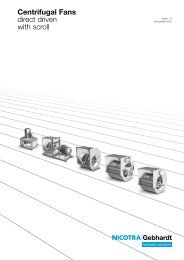
Centrifugal Fans direct driven with scroll - Nicotra Gebhardt
Centrifugal Fans direct driven with scroll - Nicotra Gebhardt
Centrifugal Fans direct driven with scroll - Nicotra Gebhardt

You also want an ePaper? Increase the reach of your titles
YUMPU automatically turns print PDFs into web optimized ePapers that Google loves.
Description<br />
Safety<br />
Performance data<br />
Sound<br />
Media<br />
Direct <strong>driven</strong> centrifugal fans / RZA / Description<br />
The fans are designed for installation in equipment and as standard are not equipped<br />
<strong>with</strong> protective guards.<br />
They should not be put into operation before all protective devices are fitted<br />
and connected!<br />
Protective measures must be carried out as set out in DIN EN ISO 12100 "Safety of<br />
machinery - Basic concepts, general principles for design".<br />
If the application of the fan allows free access to the inlet and discharge apertures,<br />
safety devices must be put in place on the fan in accordance <strong>with</strong> DIN EN ISO 13857!<br />
Suitable safety guards are available as an optional extra.<br />
The performance curves of the fans are determined at the plenum test rig according<br />
to ISO 5801.<br />
The curves show the pressure increase for a fan <strong>with</strong> free discharge as a function of<br />
the flow rate. The diagramme scale is a double logarithmical net.<br />
The throttle curves (system resistance parabolas) are then represented by straight<br />
lines.<br />
All fan curve and related data are based on a reference density of r 1 = 1,15kg/m³ for<br />
the conveyed medium at fan intake.<br />
For a medium density r 1 different to this standard value the fan curves and the motor<br />
load, as a consequence, will be changing.<br />
The efficiencies and power consumption given in the performance curves include all<br />
losses due to the motor and the frequency converter unit.<br />
The data are established for a fan <strong>with</strong> free discharge i.e. <strong>with</strong>out duct connection at<br />
the presurre side, installation A.<br />
Sound measurement and analysis are carried out in accordance <strong>with</strong> DIN 45635-38<br />
”Sound measurement at machines; fans”.<br />
The sound data of the fan curves are given as “A” weighted sound power levels L WA .<br />
The “A” weighted sound power level are identical for fan intake (L WA7 ) as well as for<br />
fan discharge (L WA6 ).<br />
An approximation of the “A” weighted sound pressure levels L pA7 /L pA6 at a distance<br />
of 1 m at fan Inlet or discharge may be obtained by subtracting 7 dB from the relative<br />
“A” weighted sound power levels.<br />
If should be noted that site acoustics, duct design, reverberation, natural frequencies<br />
etc. can all influence noise to a greater or lesser extent.<br />
For more accurate calculations to determine noise protection measures, the sound<br />
power level in each octave band is of more value.<br />
The noise correction data, in function of the fan speed and flow rate, are to be found<br />
<strong>with</strong> the corresponding table on the fan curve page.<br />
• Inlet: LWfc7 = LWA6/7 + LWrel7 • Discharge: LWfc6 = LWA6/7 + LWrel6 In some cases the noise level - calculated by this way - may in some cases be higher<br />
than expected at the blade passing frequency.<br />
Blade passing frequency<br />
N × z<br />
fBP = —<br />
60<br />
f BP = Blade passing frequency in Hz<br />
N = Fan speed in 1/min<br />
z = No of blades<br />
This range of fans are specially designed for use into air handling units (AHU) and<br />
ventilation systems.<br />
The centrifugal fans are ideal for conveying clean air. The allowed air temperature<br />
comes from -20°C to +40°C.<br />
195