Source changeover systems
Source changeover systems
Source changeover systems

You also want an ePaper? Increase the reach of your titles
YUMPU automatically turns print PDFs into web optimized ePapers that Google loves.
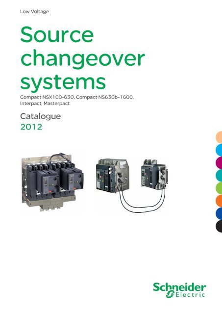
Low Voltage<br />
<strong>Source</strong><br />
<strong>changeover</strong><br />
<strong>systems</strong><br />
Compact NSX100-630, Compact NS630b-1600,<br />
Interpact, Masterpact<br />
Catalogue<br />
2012
Efficient energy<br />
management and<br />
continuity of service with<br />
source-<strong>changeover</strong> system<br />
To ensure continuity of service for critical applications,<br />
LV electrical installations need to be connected to<br />
at least two independent power sources:<br />
1<br />
2<br />
A normal<br />
source (N)<br />
And a replacement<br />
source (R)*<br />
used to supply energy to the installation<br />
when the normal source unavailable, or,<br />
for instance, when its quality and/or availability<br />
is no longer guaranteed.<br />
The source-<strong>changeover</strong><br />
system switches the<br />
load (partly or fully)<br />
between these<br />
two sources.<br />
A few basics on source-<strong>changeover</strong> <strong>systems</strong><br />
> A source-<strong>changeover</strong><br />
system can be<br />
automated to manage<br />
transfers according<br />
to external<br />
conditions.<br />
> Switching from<br />
a main power source to<br />
a replacement source<br />
can be performed<br />
either manually or<br />
automatically.<br />
> A source-<strong>changeover</strong><br />
system comprises<br />
circuit breakers,<br />
switch-disconnectors<br />
or contactors.<br />
* The replacement source (R) can be: a second power source (with possibly different<br />
characteristics from the normal source) or an electrical generator<br />
I
II<br />
3ways<br />
1<br />
2<br />
3<br />
to switch the load to meet<br />
your needs<br />
Manual source-<strong>changeover</strong> system<br />
(or MTSE: Manual Transfer Switching Equipment)<br />
The simplest way to switch the load. It is controlled manually by an operator.<br />
The time required to switch from the ‘N’ source to ‘R’ source can vary.<br />
System<br />
2 or 3 mechanically interlocked manuallyoperated<br />
circuit breakers or 2 switchdisconnectors.<br />
Automatic source-<strong>changeover</strong> system<br />
(or ATSE: Automatic Transfer Switching Equipment)<br />
An automatic controller may be added to a remote-operated source-<strong>changeover</strong> system. It is<br />
possible to automatically control source transfer according to programmed (dedicated controllers) or<br />
programmable (PLC) operating modes. These solutions ensure optimum energy management.<br />
System<br />
2 or 3 circuit breakers that may have different<br />
configurations, linked by an electrical interlocking<br />
system. A mechanical interlocking system<br />
protects against electrical malfunctions or<br />
incorrect manual operations, with an automatic<br />
control system (dedicated controllers or PLC).<br />
Applications<br />
Buildings and infrastructure where the need<br />
for continuity of service is significant but not<br />
a priority: offices, small and medium-sized<br />
businesses.<br />
Remote-operated source-<strong>changeover</strong> system<br />
(or RTSE: Remote Transfer Switching Equipment)<br />
The most commonly used system for devices with high ratings. No direct human<br />
intervention is required. <strong>Source</strong>-<strong>changeover</strong> is controlled electrically.<br />
System<br />
2 or 3 circuit breakers that may have different<br />
configurations, linked by an electrical<br />
interlocking system. In addition, a mechanical<br />
interlocking system protects against electrical<br />
malfunctions or incorrect manual operations.<br />
Applications<br />
Industry (assembly lines, engine rooms on<br />
ships, critical auxiliaries in thermal<br />
powerstations, etc.); Infrastructure (port and<br />
railway installations, runway lighting <strong>systems</strong>,<br />
control <strong>systems</strong> on military sites, etc.).<br />
Applications<br />
Commercial and service sector (operating<br />
rooms in hospitals, safety <strong>systems</strong> for<br />
buildings, computer rooms for banks and<br />
insurance companies, lighting and emergency<br />
lighting <strong>systems</strong> in malls, etc.), industry and<br />
infrastructure.
Whatever the system,<br />
you benefit from our expertise!<br />
> MTSE range<br />
Interpact<br />
From 40 A to 630 A<br />
> RTSE range<br />
Compact NSX<br />
From 100 A to 630 A<br />
> ATSE range<br />
Masterpact NT / NW<br />
From 630 A to 6300 A<br />
UA Controller Compact NSX<br />
From 100 A to 630 A<br />
Our expertise and support come together<br />
with the source-<strong>changeover</strong> system you<br />
choose for your LV electrical installation.<br />
With Interpact INS, Compact NSX<br />
and Masterpact NT and NW, we offer<br />
a complete range of solutions, designed<br />
around key values:<br />
Maximum continuity<br />
of service<br />
> Energy availability is ensured whatever<br />
the external requirements (e.g. high<br />
power demand).<br />
> Maintenance and replacement of the sources<br />
(N or R) can be done with no interruption<br />
of service.<br />
You can maintain a continuous level of service<br />
and customer satisfaction.<br />
Maximum safety<br />
For LV electrical installations where safety and<br />
continuity of service are critical for people<br />
and/or equipment such as hospitals, airports,<br />
banks, malls, etc.<br />
Optimized energy<br />
management<br />
> Transfer the load to a replacement source<br />
according to external requirements.<br />
> Manage power sources according to power<br />
quality and power costs.<br />
> Perform system regulation.<br />
> Switch to an emergency replacement source.<br />
You are no longer dependent on your power<br />
supply (and supplier)!<br />
Simplicity and reliability<br />
> Simple installation on LV switchboard.<br />
> Optimized size of the switchboard.<br />
> System based on pre-tested components.<br />
> Compliance with IEC 60947-6-1.<br />
III
IV<br />
For critical applications<br />
in particular<br />
For all others<br />
in general<br />
A source-<strong>changeover</strong> system is indispensable<br />
for applications that need a continuous supply<br />
of electric power (hospitals, airports, banks,<br />
government facilities, etc.).<br />
But a source-<strong>changeover</strong> system is also<br />
suitable for all LV electrical installations<br />
exposed to:<br />
> Nominal voltage loss or dip (when there<br />
is high demand for electric power)<br />
> Unpredictable power quality<br />
> Frequent power cuts.<br />
These factors, and many others, can damage the<br />
continuity of service of your electrical installation.<br />
For infrastructure managers, a source<strong>changeover</strong><br />
system gives direct economic<br />
benefi ts: it is possible to select your source based<br />
on power cost. In this case,<br />
the replacement source (R) is used as<br />
an alternative, more economical source.<br />
Managing<br />
energy<br />
effi ciently<br />
Power Cost<br />
Safety
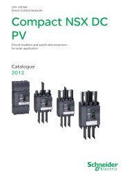
<strong>Source</strong>-<strong>changeover</strong> <strong>systems</strong><br />
Compact NSX100-630,<br />
Compact NS630b-1600,<br />
Interpact, Masterpact<br />
General content<br />
Presentation 2<br />
Functions<br />
and characteristics<br />
A-1<br />
Dimensions B-1<br />
Electrical diagrams C-1<br />
Catalogue numbers<br />
and order forms<br />
D-1
PB 050 4<br />
PB390385_SE_R_35<br />
PB 0478 _R<br />
Presentation<br />
Incoming feeders and main LV switchboards<br />
Currents<br />
From 630 to 6300 A.<br />
Power distribution<br />
Currents<br />
From 250 to 3200 A.<br />
Loads<br />
Currents<br />
From 40 to 400 A.<br />
DB 0 543<br />
For maximum continuity<br />
of service...
DB 0 538<br />
DB 0 54<br />
DB 0 54<br />
normal source<br />
replacement source<br />
DB 0 539<br />
sources with coupler on<br />
busbars<br />
DB 0 540<br />
normal sources<br />
replacement source<br />
QN QR QS1 QC QS2 QN1 QN2 QR<br />
0 0 0 0 0 0 0 0<br />
0 0 0<br />
0 0 0 0<br />
0 0 0<br />
0 0 (1) 0 0<br />
0 0 (1)<br />
Generator or permanent<br />
source<br />
Generator or permanent<br />
source<br />
DB 0 544<br />
Generator or permanent<br />
source<br />
... in a wide range of applications<br />
(1) possible by forcing<br />
operation.<br />
QN QR Typical applications:<br />
0 0<br />
0<br />
0<br />
b continuous production processes<br />
b operating rooms<br />
b computer rooms...<br />
QN QR Typical applications:<br />
0 0<br />
0<br />
0<br />
b large electrical installations (e.g. airports)<br />
b refrigeration units<br />
b special electricity tariffs<br />
b pumping stations...<br />
3
TOOLS<br />
schneider-electric.com<br />
This international site allows you<br />
to access all the Schneider Electric<br />
Solution and Product information<br />
via :<br />
p comprehensive descriptions<br />
p range data sheets<br />
p a download area<br />
p product selectors<br />
p ..<br />
You can also access the information<br />
dedicated to your business and get<br />
in touch with your Schneider Electric<br />
country support.
<strong>Source</strong>-<strong>changeover</strong> <strong>systems</strong><br />
Compact NSX100-630,<br />
Compact NS630b-1600,<br />
Interpact, Masterpact<br />
Functions and characteristics<br />
Presentation 2<br />
Overview of solutions A-2<br />
Manual source-<strong>changeover</strong> <strong>systems</strong><br />
Interpact INS/INV40 to 630 A, Compact NSX100/630 A A-2<br />
Manual source-<strong>changeover</strong> <strong>systems</strong> Compact NS<br />
and Masterpact NT/NW 630 A to 6300 A A-3<br />
Remote-operated source-<strong>changeover</strong> <strong>systems</strong><br />
Compact NSX100/630, Compact NS630b/1600 A A-4<br />
Remote-operated source-<strong>changeover</strong> <strong>systems</strong><br />
Masterpact NT/NW 630 A to 6300 A A-5<br />
Manual source-<strong>changeover</strong> <strong>systems</strong> A-6<br />
Possible combinations A-6<br />
Remote-operated source-<strong>changeover</strong> <strong>systems</strong> A-10<br />
Mechanical interlocking Compact NSX, Compact NS or Masterpact NT/NW A-10<br />
Mechanical interlocking Compact NS or Masterpact NT/NW A-11<br />
General characteristics Compact NSX A-12<br />
General characteristics Compact NS, Masterpact NT/NW A-13<br />
Mechanical and electrical durability Interpact INS,<br />
Compact NSX, NS, Masterpact NT/NW A-14<br />
Connection and insulation accessories for Compact NSX and INS y 630 A A-15<br />
Electrical interlocking A-16<br />
Standard configurations A-17<br />
Associated controllers A-18<br />
Controller selection A-18<br />
Controller installation A-19<br />
BA controller A-20<br />
BA controller, Operating sequences A-21<br />
UA controller A-22<br />
UA controller, Operating sequences, Forced operation mode A-23<br />
UA controller, Operating sequences, Special-tariff mode A-24<br />
UA controller, Operating sequences, Test mode and automatic operation A-25<br />
Operating sequences A-26<br />
IVE unit A-26<br />
BA/UA controller A-27<br />
COM communications option A-28<br />
Dimensions B-1<br />
Electrical diagrams C-1<br />
Catalogue numbers and order forms D-1<br />
A-1
DB 6589<br />
DB 6590<br />
DB 6588<br />
DB 6587<br />
DB 6586<br />
Functions<br />
and characteristics<br />
Range Interpact Compact<br />
Models INS40 to INS80<br />
INS 00 to INS 60<br />
A-<br />
INS 50 to INS630<br />
INV 50 to INV630<br />
NSX 00 to NSX 50<br />
NSX400 to NSX630<br />
Rating (A) 40 to 60 00 to 630 00 to 630<br />
Type of device Switch-disconnectors with<br />
extended handles<br />
Manual source-<strong>changeover</strong> <strong>systems</strong><br />
Interlocking via toggles<br />
2 devices side-by-side. 3 devices side-by-side.<br />
Interlocking via rotary handles<br />
2 devices side-by-side.<br />
Interlocking via keylocks with captive keys<br />
A number of different devices.<br />
Interlocking on a base plate<br />
2 devices side-by-side.<br />
Complete source-<strong>changeover</strong> assemblies<br />
2 devices side-by-side.<br />
Overview of solutions<br />
Manual source-<strong>changeover</strong> <strong>systems</strong><br />
Interpact INS/INV 40 to 630 A,<br />
Compact NSX100/630<br />
DB 0 546<br />
.4 .4<br />
22<br />
NN<br />
Switch-disconnectors N/H/L circuit breakers<br />
NA switch-disconnectors<br />
DB 0 547<br />
DB 0 549<br />
DB 0 55<br />
DB 0 545<br />
DB 0 548<br />
DB 0 550<br />
DB 0 55<br />
ON ON<br />
II<br />
OO<br />
OFF OFF<br />
ON ON<br />
II<br />
OO<br />
OFF OFF
DB 6590<br />
DB 6588<br />
DB 6585<br />
DB 6584<br />
DB 6583<br />
DB 6580<br />
Range Compact Masterpact<br />
Models NS630b to NS 600 NT06 to NT 6 NW08 to NW63<br />
Rating (A) 630 to 600 630 to 600 800 to 6300<br />
Type of device N/H/L circuit breakers<br />
NA switch-disconnectors<br />
Manual source-<strong>changeover</strong> <strong>systems</strong><br />
Interlocking via extended rotary handles<br />
2 devices side-by-side.<br />
Interlocking via keylocks with captive keys<br />
A number of different devices.<br />
Mechanical interlocking using connecting rods<br />
2 devices one above the other.<br />
Mechanical interlocking using cables<br />
2 or 3 devices one above the other.<br />
2 or 3 devices side-by-side.<br />
For this case and other cases, please consult us<br />
Manual source-<strong>changeover</strong> <strong>systems</strong><br />
Compact NS and Masterpact NT/NW<br />
630 A to 6300 A<br />
DB 0 553<br />
DB 0 554<br />
DB 0 557<br />
(1)<br />
DB 0 560<br />
(1)<br />
(2)<br />
H /L circuit breakers<br />
HA switch-disconnectors<br />
(1) Implemented with NS630b to NS1600 electrically-operated devices only.<br />
(2) For source-<strong>changeover</strong> <strong>systems</strong> using cables, always respect the installation conditions specified on page A-13.<br />
OFF O OFF O<br />
OFF O OFF O<br />
I O<br />
I O<br />
I O<br />
I O<br />
OFF<br />
push ON<br />
push OFF<br />
push ON<br />
push<br />
OFF<br />
push ON<br />
push OFF<br />
push ON<br />
push<br />
discharged<br />
discharged<br />
discharged<br />
discharged<br />
DB 0 555<br />
DB 0 558<br />
DB 0 56<br />
OO<br />
II<br />
push push OFF OFF<br />
push push ON ON<br />
OO OFF OFF<br />
discharged<br />
discharged<br />
OO<br />
II<br />
push push OFF OFF<br />
push push ON ON<br />
OO OFF OFF<br />
discharged<br />
discharged<br />
N /H /H /H3/L circuit<br />
breakers<br />
NA/HA/HF switchdisconnectors<br />
DB 0 556<br />
DB 0 559<br />
DB 0 56<br />
A-3
DB 6587<br />
DB 6585<br />
DB 658<br />
DB 658<br />
DB 658<br />
DB 658<br />
Functions<br />
and characteristics<br />
Range Compact<br />
Models NSX 00 to NSX630 NS630b to NS 600<br />
Rating (A) 00 to 630 630 to 600<br />
Type of device N/H/L circuit breakers<br />
NA switch-disconnectors<br />
Remote-operated source-<strong>changeover</strong> system<br />
Mechanical interlocking on base plate + electrical interlocking<br />
2 electrically-operated devices side-by-side combined<br />
with an electrical interlocking system.<br />
Mechanical interlocking using connecting rods + electrical interlocking<br />
2 electrically-operated devices one above<br />
the other combined with an electrical interlocking system.<br />
Mechanical interlocking using cables + electrical interlocking<br />
2 electrically-operated devices one above<br />
the other combined with an electrical interlocking system.<br />
2 electrically-operated devices side-by-side combined<br />
with an electrical interlocking system.<br />
Automatic source-<strong>changeover</strong> <strong>systems</strong><br />
Remote-operated source-<strong>changeover</strong> system combined with an automatic-control system<br />
A-4<br />
The automatic controller<br />
operates the devices<br />
depending on external<br />
parameters.<br />
BA: Simple controller that<br />
manages the <strong>changeover</strong><br />
function.<br />
UA: Controller that also<br />
manages engine generator<br />
sets.<br />
UA150: UA controller with a<br />
communication option.<br />
Overview of solutions<br />
Remote-operated source-<strong>changeover</strong><br />
<strong>systems</strong> Compact NSX100/630,<br />
Compact NS630b/1600 A<br />
(2) For source-<strong>changeover</strong> <strong>systems</strong> using cables, always respect the installation conditions specified on page A-13.<br />
DB 0 563<br />
DB 597<br />
DB 5963<br />
N/H/L circuit breakers<br />
NA switch-disconnectors<br />
DB 0 557<br />
DB 0 560<br />
(2)<br />
OFF O OFF O<br />
OFF O OFF O<br />
I O<br />
I O<br />
I O<br />
I O<br />
OFF<br />
push ON<br />
push OFF<br />
push ON<br />
push<br />
OFF<br />
push ON<br />
push OFF<br />
push ON<br />
push<br />
discharged<br />
discharged<br />
discharged<br />
discharged<br />
BA controller<br />
UA and UA150 controller
DB 6585<br />
DB 6584<br />
DB 6583<br />
DB 658<br />
DB 658<br />
Range Masterpact<br />
Models NT06 to NT 6 NW08 to NW63<br />
Rating (A) 630 to 600 800 to 6300<br />
Type of device H /L circuit breakers<br />
HA switch-disconnectors<br />
Remote-operated source-<strong>changeover</strong> system<br />
Mechanical interlocking using connecting rods + electrical interlocking<br />
2 electrically-operated devices side-by-side combined<br />
with an electrical interlocking system.<br />
Mechanical interlocking using cables + electrical interlocking<br />
2 or 3 electrically-operated devices one above the other<br />
combined with an electrical interlocking system (1) .<br />
2 or 3 electrically-operated devices side-by-side combined with<br />
an electrical interlocking system (1) .<br />
Automatic source-<strong>changeover</strong> <strong>systems</strong><br />
Remote-operated source-<strong>changeover</strong> system combined with an automatic-control system<br />
The automatic controller<br />
operates the devices<br />
depending on external<br />
parameters.<br />
BA: Simple controller that<br />
manages the <strong>changeover</strong><br />
function.<br />
UA: Controller that also<br />
manages engine generator<br />
sets.<br />
UA150: UA controller with a<br />
communication option.<br />
Remote-operated source-<strong>changeover</strong><br />
<strong>systems</strong> Masterpact NT/NW<br />
630 A to 6300 A<br />
(1) Three devices with Masterpact NW only.<br />
(2) For source-<strong>changeover</strong> <strong>systems</strong> using cables, always respect the installation conditions specified on page A-13.<br />
For other cases, please consult us.<br />
DB 0 558<br />
DB 0 56<br />
(2)<br />
DB 597<br />
DB 5963<br />
N /H /H /H3/L circuit breakers<br />
NA/HA/HF switch-disconnectors<br />
DB 0 559<br />
DB 0 56<br />
BA controller<br />
UA and UA150 controller<br />
A-5
Functions<br />
and characteristics<br />
A manual source-<strong>changeover</strong> system can be installed<br />
on two or three manually-operated and mechanically<br />
interlocked circuit breakers or switch-disconnectors.<br />
Interlocks prevent connection to both sources at the<br />
same time, even momentarily.<br />
A-6<br />
All possibilities for manual source-<strong>changeover</strong> <strong>systems</strong><br />
Type of device Type of interlocking for two devices<br />
Complete<br />
assembly<br />
Interpact switch-disconnectors<br />
INS40 to INS160<br />
INS250-100 to INS630<br />
INV100 to 630<br />
Type of device Type of interlocking for two devices<br />
Toggle Keylock Direct rotary<br />
handle<br />
Compact fixed or withdrawable circuit breakers<br />
b<br />
Keylock Direct rotary<br />
handle<br />
b b r b r<br />
Extended<br />
rotary handle<br />
b b r b r r<br />
INS/INV630b to 2500<br />
b<br />
Legend:<br />
r Possible but visible break function disabled.<br />
r 250 A and 630 A ratings can be mixed by using INS320/630 rotary handle interlocking system.<br />
Extended rotary<br />
handle<br />
On base plate<br />
On base plate<br />
(toggle or direct extended (motor mechanism)<br />
rotary control)<br />
NSX100 to 250 b b b b p b b b b b b b b b b<br />
NSX400 to NS630 b b b b p b b b b b b b b b b<br />
NSX100 to 630 b b p b b p b b p b b b p b b b p<br />
NS630b to 1600 with<br />
rotary handle<br />
Legend:<br />
b Fixed devices only.<br />
b Fixed or withdrawable devices.<br />
b b p b b b b<br />
b Devices must be either both fixed or both withdrawable.<br />
p With NSX400/630 rotary handle interlocking system.<br />
p Possible with NSX400/630 base plate + NSX100-250 adaptation kit.<br />
p Devices equipped with rotary handles.<br />
Type of device Type of interlocking for either all fixed or all withdrawable devices<br />
Keylock Cable-type,<br />
2 devices side-byside<br />
Cable-type,<br />
3 devices side-byside<br />
Cable-type,<br />
2 devices one<br />
above the other<br />
Compact fixed or withdrawable circuit breakers or swith-disconnectors, with motor mechanism<br />
Cable-type,<br />
3 devices one<br />
above another<br />
NS630b to 1600 b b b b<br />
Masterpact fixed or withdrawable circuit breakers or swith-disconnectors, manual operation or with motor mechanism<br />
NT06 to 16 b b b b<br />
NW08 to 63 b b b b b b<br />
NT06 to NW63 b b b<br />
Manual source-<strong>changeover</strong><br />
<strong>systems</strong><br />
Possible combinations<br />
b<br />
Rod-type,<br />
3 devices one<br />
above another
DB 0 57<br />
DB 0 566<br />
Complete source-<strong>changeover</strong> assembly for two switch-disconnectors<br />
All possibilities for manual source-<strong>changeover</strong> <strong>systems</strong><br />
These assemblies provide an easy way to implement source <strong>changeover</strong> functions<br />
with:<br />
b a single 3-position rotary handle that controls the two switch-disconnectors<br />
(Normal source ON, OFF, Replacement source ON)<br />
b a smaller size, taking up less room in the switchboard.<br />
A complete source <strong>changeover</strong> assembly can be ordered with a single catalogue<br />
number.<br />
“Normal N” “Replacement” R<br />
INS250-100 INS250-160 INS200-200 INS250-250 INS320 INS400 INS500 INS630<br />
INS250-100<br />
Ratings 00 A<br />
INS250-160<br />
b<br />
Ratings 60 A<br />
INS200-200<br />
b<br />
Ratings 00 A<br />
INS250-250<br />
b<br />
Ratings 50 A<br />
INS320<br />
b<br />
Ratings 3 0 A<br />
INS400<br />
b<br />
Ratings 400 A<br />
INS500<br />
b<br />
Ratings 500 A<br />
INS630<br />
b<br />
Ratings 630 A<br />
b<br />
Interlocking of two or three toggle-controlled devices<br />
Possible combinations of “Normal” and “Replacement” source circuit breakers<br />
Possible combinations<br />
Two devices can be interlocked using this system. Two identical interlocking <strong>systems</strong><br />
can be used to interlock three devices installed side by side, in which case one<br />
device is in the ON position and the two others are in the OFF position. Devices must<br />
all have the same configuration, i.e. fixed, plug-in, withdrawable or drawout.<br />
The system is locked using one or two padlocks (shackle diameter 5 to 8 mm).<br />
Two interlocking system models are available for:<br />
b Compact NSX 00 to 50<br />
b Compact NSX400 to 630.<br />
“Normal N” “Replacement” R<br />
NSX100 NSX160 NSX250 NSX400 NSX630<br />
NSX100<br />
Ratings 6... 00 A<br />
NSX160<br />
b<br />
b<br />
b<br />
b<br />
b<br />
Ratings 80... 60 A<br />
NSX250<br />
b<br />
b<br />
b<br />
b<br />
b<br />
Ratings<br />
NSX400<br />
5... 50 A b<br />
b<br />
b<br />
b<br />
b<br />
Ratings 50... 400 A<br />
NSX630<br />
b<br />
b<br />
b<br />
b<br />
b<br />
Ratings 630 A<br />
b<br />
b<br />
b<br />
b<br />
b<br />
A-7
DB 0 569<br />
DB 0 568<br />
Functions<br />
and characteristics<br />
Interlocking of a number of devices using keylocks (captive keys)<br />
Combination of “Normal” and “Replacement” devices<br />
Interlocking of two devices with rotary handles<br />
Possible combinations of “Normal” and “Replacement” source circuit breakers<br />
A-8<br />
ON ON<br />
II<br />
OO<br />
OFF OFF<br />
ON ON<br />
II<br />
OO<br />
OFF OFF<br />
Manual source-<strong>changeover</strong><br />
<strong>systems</strong><br />
Possible combinations<br />
All Interpact, Compact and Masterpact circuit breakers and switch-disconnectors<br />
from 00 to 6300 A with rotary handles or motor mechanisms can be interlocked.<br />
Interlocking is based on two identical keylocks with a single key and a keylock<br />
adapter (different for each device). This solution enables interlocking between two<br />
devices that are physically distant or that have very different characteristics, for<br />
example between a low and a medium-voltage device, or between Compact NSX<br />
circuit breakers and switch-disconnectors.<br />
A system of wall-mounted captive key boxes makes possible a large number of<br />
combinations between many devices.<br />
The direct or extended rotary handles are padlocked with the devices in the OFF<br />
position. The mechanism prevents simultaneous closing of the devices, but allows<br />
them to be opened.<br />
“Normal N” “Replacement” R<br />
Compact NSX100/630 (1) NSX100<br />
NSX100 NSX160 NSX250 NSX400 NSX630<br />
Ratings 6... 00 A<br />
NSX160<br />
b b b v<br />
v<br />
Ratings 80... 60 A<br />
NSX250<br />
b b b v<br />
v<br />
Ratings<br />
NSX400<br />
5... 50 A<br />
b b b v<br />
v<br />
Ratings 60... 400 A<br />
NSX630<br />
v<br />
v<br />
v<br />
b b<br />
Ratings 630 A<br />
v<br />
v<br />
v<br />
b b<br />
v 250 A and 630 A ratings can be mixed by using NSX400/630 rotary handle interlocking<br />
system.<br />
“Normal N” “Replacement” R<br />
Compact NS630b/1600 (1) NS630b<br />
NS630b NS800 NS1000 NS1200 NS1600<br />
Ratings 50... 630 A<br />
NS800<br />
b b b b b<br />
Ratings 3 0... 800 A<br />
NS1000<br />
b b b b b<br />
Ratings 400... 000 A<br />
NS1200<br />
b b b b b<br />
Ratings 480...<br />
NS1600<br />
00 A b b b b b<br />
Ratings 640... 600 A b b b b b<br />
(1) When mixing NSX100/250 and NSX400/630 circuit breakers, use the NSX400/630<br />
interlocking system.
DB 0774<br />
DB 0 570<br />
DB 0 903<br />
Interlocking of two devices with rotary handles<br />
Possible combinations of “Normal” and “Replacement” source switch-disconnectors<br />
The direct or extended rotary handles are padlocked with the devices in the OFF<br />
position. The mechanism prevents simultaneous closing of the devices, but allows<br />
them to be opened.<br />
“Normal N” “Replacement” R<br />
Interpact INS (1) INS40<br />
INS40 INS63 INS80 INS100 INS125 INS160<br />
Ratings 40 A<br />
INS63<br />
b b b b b b<br />
Ratings 63 A<br />
INS80<br />
b b b b b b<br />
Ratings 80 A<br />
INS100<br />
b b b b b b<br />
Ratings 00 A<br />
INS125<br />
b b b b b b<br />
Ratings<br />
INS160<br />
5 A<br />
b b b b b b<br />
Ratings 60 A<br />
b b b b b b<br />
(1) With extended rotary handles only.<br />
(2) Possible with INV, but visible-break function is significantly impaired.<br />
“Normal N” “Replacement” R<br />
Interpact INS /INV (2) INS250-100/ INS250-160/ INS250-200/ INS250-250/ INS320/ INS400/ INS500/ INS630/<br />
INS250-100/INV100<br />
INV100 INV160 INV200 INV250 INV320 INV400 INV500 INV630<br />
Ratings 00 A<br />
INS250-160/INV160<br />
b<br />
b<br />
b<br />
b<br />
v<br />
v<br />
v<br />
Ratings 60 A<br />
INS250-200/INV200<br />
b<br />
b<br />
b<br />
b<br />
Ratings 00 A<br />
INS250-250/INV250<br />
b<br />
b<br />
b<br />
b<br />
Ratings 50 A<br />
INS320/INV320<br />
b<br />
b<br />
b<br />
b<br />
v<br />
v<br />
Ratings 3 0 A<br />
INS400/INV400<br />
v<br />
v b b b b<br />
Ratings 400 A<br />
INS500/INV500<br />
b<br />
b<br />
b<br />
b<br />
Ratings 500 A<br />
INS630/INV630<br />
b<br />
b<br />
b<br />
b<br />
Ratings 630 A<br />
v<br />
v b b b b<br />
v 250 A and 630 A ratings can be mixed by using INS320/630 rotary handle interlocking system.<br />
Interlocking of two devices on a base plate<br />
Possible combinations of Compact NSX “Normal” and “Replacement” source circuit breakers<br />
A base plate is available for mechanical interlocking of two manually-operated<br />
Compact NSX 00 to 630 circuit breakers or switch-disconnectors.<br />
“Normal N” “Replacement” R<br />
NSX100 NSX160 NSX250 NSX400 NSX630<br />
push push<br />
to to<br />
trip trip<br />
push push<br />
to to<br />
trip trip<br />
Possible combinations<br />
NSX100<br />
Ratings 6... 00 A<br />
NSX160<br />
Ratings 80... 60 A<br />
NSX250<br />
Ratings 5... 50 A<br />
NSX400<br />
Ratings 50... 400 A<br />
NSX630<br />
Ratings 630 A<br />
Interlocking of a number of devices using keylocks<br />
Combination of Masterpact devices<br />
Interlocking uses two identical keylocks with a single key. This solution enables<br />
interlocking between two devices that are physically distant or that have significantly<br />
different characteristics.<br />
b<br />
b<br />
b<br />
b<br />
b<br />
b<br />
b<br />
b<br />
b<br />
b<br />
b<br />
b<br />
b<br />
b<br />
b<br />
b<br />
b<br />
b<br />
b<br />
b<br />
b<br />
b<br />
b<br />
b<br />
b<br />
A-9
PB 0383 _5<br />
DB 6 68<br />
Functions<br />
and characteristics<br />
Mechanical interlocking of two or three devices is used<br />
to create a remote-operated source-<strong>changeover</strong><br />
system. A basic mechanical interlocking system<br />
enhances the reliability of system operation.<br />
Interlocking of two electrically-operated Compact NSX<br />
circuit breakers using a base plate.<br />
Interlocking of two Masterpact NT or NW circuit breakers using<br />
connecting rods.<br />
A- 0<br />
Remote-operated<br />
source-<strong>changeover</strong> <strong>systems</strong><br />
Mechanical interlocking Compact NSX,<br />
Compact NS or Masterpact NT/NW<br />
Interlocking of two Compact NSX100 to 630 devices using a<br />
base plate<br />
A base plate designed for two Compact circuit breakers can be installed horizontally<br />
or vertically on a mounting rail. Interlocking is carried out on the base plate by a<br />
mechanism located behind the breakers. Access to the circuit breaker controls and<br />
trip units is conserved. Circuit breakers must be fixed or plug-in versions, with or<br />
without earth-leakage protection or measurement modules. The base plate and the<br />
circuit breakers are supplied separately.<br />
b Base plate for Compact NSX100 to 250 devices<br />
This base plate is intended for two Compact NSX 00 to 50 devices.<br />
b Base plate for Compact NSX400 to 630 devices<br />
This base plate is intended for two Compact NSX400 to 630 devices. It may also be<br />
used, without any modifications, to interlock a fixed Compact NSX 00 to 50 with a<br />
Compact NSX400 or 630 device.<br />
An adapter kit is required for plug-in versions of the Compact NSX 00 to 50<br />
devices.<br />
Compact NSX 00 to 50 devices, in both fixed and plug-in versions, may be<br />
equipped with spreaders.<br />
Possible combinations of “Normal” and “Replacement” Compact NSX source circuit<br />
breakers<br />
“Normal N” “Replacement” R<br />
NSX100 NSX160 NSX250 NSX400 NSX630<br />
NSX100<br />
Ratings<br />
NSX160<br />
,5... 00 A b<br />
b<br />
b<br />
b<br />
b<br />
Ratings<br />
NSX250<br />
,5... 60 A b<br />
b<br />
b<br />
b<br />
b<br />
Ratings<br />
NSX400<br />
,5... 50 A b<br />
b<br />
b<br />
b<br />
b<br />
Ratings 60... 400 A<br />
NSX630<br />
b<br />
b<br />
b<br />
b<br />
b<br />
Ratings 50... 630 A b<br />
b<br />
b<br />
b<br />
b<br />
Interlocking of two Compact NS630b to 1600 or two Masterpact<br />
NT and NW devices using connecting rods<br />
The two devices must be mounted one above the other (either fixed or<br />
withdrawable/drawout devices).<br />
Combinations are possible between Compact NS630b to NS 600 devices and<br />
between Masterpact NT and Masterpact NW devices.<br />
Installation<br />
This function requires:<br />
b an adaptation fixture on the right side of each circuit breaker or switchdisconnector<br />
b a set of connecting rods with no-slip adjustments.<br />
The adaptation fixtures, connecting rods and circuit breakers or switchdisconnectors<br />
are supplied separately, ready for assembly by the customer.<br />
The maximum vertical distance between the fixing planes is 900 mm.<br />
Possible combinations of “Normal” and “Replacement” source circuit breakers<br />
“Normal N” “Replacement” R<br />
NS630b to NS1600<br />
Ratings 50... 600 A<br />
NT06 to NT16<br />
Ratings 50... 600 A<br />
NW08 to NW40<br />
Ratings 3 0... 4000 A<br />
NW40b to NW63<br />
Ratings 4000... 6300 A<br />
NS630b to<br />
NS1600<br />
b<br />
NT06 to NT16 NW08 to<br />
NW40<br />
b<br />
b<br />
b<br />
b<br />
b<br />
b<br />
NW40b to<br />
NW63<br />
b<br />
b<br />
b
PB 0084 -68_SE<br />
Interlocking of two Masterpact circuit breakers using cables.<br />
Mechanical interlocking<br />
Compact NS or Masterpact NT/NW<br />
Interlocking of two Compact NS630b to 1600 or two Masterpact<br />
NT/NW or up to three Masterpact NW devices using cables<br />
For cable interlocking, the circuit breakers may be mounted one above the other or<br />
side-by-side.<br />
The interlocked devices may be fixed or drawout, three-pole or four-pole, and have<br />
different ratings and sizes.<br />
Interlocking between two devices (Compact NS630b to 1600 or Masterpact NT<br />
and NW)<br />
This function requires:<br />
b an adaptation fixture on the right side of each device<br />
b a set of cables with no-slip adjustments.<br />
The maximum distance between the fixing planes (vertical or horizontal) is 000 mm.<br />
Interlocking between three devices (Masterpact NW only)<br />
This function requires:<br />
b a specific adaptation fixture for each type of interlocking, installed on the right side<br />
of each device<br />
b two or three sets of cables with no-slip adjustments.<br />
The maximum distance between the fixing planes (vertical or horizontal) is 000 mm.<br />
Installation<br />
The adaptation fixtures, sets of cables and circuit breakers or switch-disconnectors<br />
are supplied separately, ready for assembly by the customer.<br />
Installation conditions for cable interlocking <strong>systems</strong>:<br />
b cable length: .5 m<br />
b radius of curvature: 00 mm<br />
b maximum number of curves: 3.<br />
Possible combinations of “Normal” and “Replacement” source circuit breakers<br />
“Normal N” “Replacement” R<br />
NS630b to NS1600<br />
Ratings 50... 600 A<br />
NT06 to NT16<br />
Ratings 50... 600 A<br />
NW08 to NW40<br />
Ratings 3 0... 4000 A<br />
NW40b to NW63<br />
Ratings 4000... 6300 A<br />
NS630b to<br />
NS1600<br />
b<br />
NT06 to NT16 NW08 to<br />
NW40<br />
b<br />
b<br />
b<br />
b<br />
NW40b to<br />
NW63<br />
It is not possible to combine Compact NS630b to 600 and Masterpact NT<br />
(or Masterpact NW) devices.<br />
All combinations of two Masterpact NT and Masterpact NW devices are possible,<br />
whatever the rating or size of the devices.<br />
Possible combinations of three device<br />
“Normal N” “Replacement” R<br />
NS630b to NS1600<br />
Ratings 50... 600 A<br />
NT06 to NT16<br />
Ratings 50... 600 A<br />
NW08 to NW40<br />
Ratings 3 0... 4000 A<br />
NW40b to NW63<br />
Ratings 4000... 6300 A<br />
NS630b to<br />
NS1600<br />
b<br />
b<br />
NT06 to NT16 NW08 to<br />
NW40<br />
Only Masterpact NW may be used for three-device combinations.<br />
Types of mechanical interlocking and combinations<br />
See page A-4 to page A-9.<br />
b<br />
b<br />
b<br />
b<br />
b<br />
NW40b to<br />
NW63<br />
b<br />
b<br />
A-
Functions<br />
and characteristics<br />
Range Compact NSX<br />
Types of devices NSX 00 to NSX 50 NSX400 to NSX630<br />
Types of circuit breakers N / H / L N / H / L<br />
Switch-disconnector version NA NA<br />
Mixing possibilities all devices all devices<br />
NS 00 to NS 50 NS 00 to NS630<br />
N/H/L/NA N/H/L/NA<br />
fixed or plug-in fixed or plug-in<br />
Electrical characteristics<br />
Rating 5 to 50 A 5 to 630 A<br />
Insulating voltage Ui (V AC) 750 750<br />
Positive break indication<br />
b<br />
b<br />
Number of poles<br />
(N and R devices must have the same number of poles)<br />
3, 4<br />
Electrical durability See page A- 4<br />
Operating temperature<br />
Control characteristics<br />
- 5 °C to +70 °C (50 °C for 440 V - 60 Hz)<br />
Control voltage AC 48 V - 50 Hz 48 V - 50 Hz<br />
0/ 30, 0/ 40, 380/440 V - 50/60 Hz 0/ 30, 0/ 40, 380/440 V - 50/60 Hz<br />
DC 4- 50 V 4- 50 V<br />
Maximum consumption AC 500 VA 500 VA<br />
DC 500 W 500 W<br />
Minimum switching time<br />
Interlocking<br />
Mechanical (see page A- 0)<br />
800 ms 800 ms<br />
Electrical by diagram (without IVE)<br />
b<br />
b<br />
with IVE unit<br />
b<br />
b<br />
auxiliary contacts used by circuit breaker OF + SDE OF + SDE<br />
Protection and measurement<br />
Overload protection long time b<br />
b<br />
Short-circuit protection short time b<br />
b<br />
instantaneous b<br />
b<br />
Earth-fault protection<br />
b<br />
Zone selective interlocking (ZSI)<br />
b<br />
Earth-leakage protection by Vigi module<br />
by control unit<br />
b<br />
b<br />
Current measurements<br />
by add-on Vigirex relay b<br />
b<br />
Voltage, frequency, power measurements, etc.<br />
Indication and control auxiliaries<br />
Available auxiliary indication contacts OF + SD (+ SDV) 3 OF + SD (+ SDV)<br />
Voltage releases MX shunt<br />
b<br />
b<br />
MN undervoltage<br />
b<br />
b<br />
Voltage presence indicator<br />
b<br />
b<br />
Voltage transformer<br />
b<br />
b<br />
Ammeter module<br />
b<br />
b<br />
Insulation monitoring module<br />
b<br />
b<br />
<strong>Source</strong>-<strong>changeover</strong> controller<br />
With permanent replacement source b BA controller<br />
With standby generator set<br />
Remote communication via bus<br />
Device status indications<br />
Device remote control<br />
b UA controller<br />
Transmission of settings<br />
b<br />
b<br />
Indication and identification of protection status and alarms b<br />
b<br />
Transmission of measurements<br />
Installation and connection<br />
Fixed front connected<br />
b<br />
b<br />
Fixed rear connected b (long rear connections)<br />
b (long rear connections)<br />
Withdrawable, plug-in or drawout<br />
Installation and connection accessories<br />
b (plug-in on base)<br />
b (plug-in on base)<br />
Downstream coupling accessory<br />
b<br />
b<br />
Bare-cable connectors<br />
b<br />
b<br />
Terminal extensions<br />
b<br />
b<br />
Terminal shields and inter-phase barriers<br />
b<br />
Locking by padlock<br />
b<br />
b<br />
by keylock<br />
b<br />
b<br />
Front panel escutcheons<br />
b<br />
b<br />
A-<br />
Remote-operated<br />
source-<strong>changeover</strong> <strong>systems</strong>0<br />
General characteristics<br />
Compact NSX
Compact NS Masterpact<br />
NS630b to NS 600 NT06 to 6 NW08 to 63<br />
N / H / L N / H / H / H3 / L N / H / H / H3 / L<br />
NA NA / HA / HF NA / HA / HF<br />
all devices all mixing possibilities all mixing possibilities<br />
NS630b to 600 (fixed, drawout or fixed + drawout) (fixed, drawout or fixed + drawout)<br />
N/H/L/NA N /H /H /H3/L /NA/HA/HF N /H /H /H3/L /NA/HA/HF<br />
fixed or plug-in<br />
50 to 600 A 600 to 600 A 800 to 6300 A<br />
750 000 000<br />
b<br />
3, 4<br />
b<br />
See page A- 4<br />
– 5 °C to +70 °C (50 °C for 440 V - 60 Hz)<br />
48 to 4 5 V - 50/60 Hz<br />
440 V - 60 Hz<br />
4- 50 V 4- 50 V 4- 50 V<br />
80 VA 80 VA 80 VA<br />
80 W 80 W 80 W<br />
800 ms 800 ms 800 ms<br />
b<br />
b<br />
b<br />
b only with UA or BA only with UA or BA<br />
OF + CE (+ SDE) OF + CE + PF OF + CE + PF<br />
b<br />
b<br />
b<br />
b<br />
b<br />
b<br />
b<br />
b<br />
OF + SD OF + SD OF + SD<br />
b<br />
b<br />
b<br />
b<br />
b<br />
b<br />
b<br />
b<br />
b<br />
b<br />
b<br />
b<br />
b<br />
b<br />
b<br />
b<br />
b<br />
b<br />
b<br />
b<br />
b<br />
b<br />
b<br />
b<br />
b<br />
b<br />
b<br />
b BA controller<br />
b UA controller<br />
b<br />
b<br />
b<br />
b<br />
b (vertical or horizontal)<br />
b (vertical or horizontal)<br />
b (vertical or horizontal)<br />
b (drawout)<br />
b (drawout)<br />
b (drawout)<br />
b<br />
b<br />
b<br />
b<br />
b<br />
General characteristics<br />
Compact NS, Masterpact NT/NW<br />
b<br />
b<br />
b<br />
b<br />
b<br />
b<br />
b<br />
b<br />
b<br />
b<br />
b<br />
b<br />
b<br />
b<br />
b<br />
b<br />
b<br />
b<br />
b<br />
A- 3
Functions<br />
and characteristics<br />
Interpact INS switch-disconnectors<br />
INS250-100 INS250-160 INS250-200 INS250<br />
Number of poles 3, 4 3, 4 3, 4 3, 4<br />
Conventional thermal current (A) lth at 60 °C 100 160 200 250<br />
Rated operational current (A) Ie Electrical AC, 50/60 Hz AC22A AC23A AC22A AC23A AC22A AC23A AC22A AC23A<br />
440-480 V 100 100 160 160 200 200 250 250<br />
660-690 V 100 100 160 160 200 200 250 250<br />
Durability (category A)<br />
(O N -C R -O R -C N cycles)<br />
A-14<br />
Mechanical 15000 15000 15000 15000<br />
Electrical AC, 50/60 Hz AC22A AC23A AC22A AC23A AC22A AC23A AC22A AC23A<br />
440-480 V 1500 1500 1500 1500 1500 1500 1500 1500<br />
660-690 V 1500 1500 1500 1500 1500 1500 1500 1500<br />
INS320 INS400 INS500 INS630<br />
Number of poles 3, 4 3, 4 3, 4 3, 4<br />
Conventional thermal current (A) lth at 60 °C 320 400 500 630<br />
Rated operational current (A) Ie Electrical AC, 50/60 Hz AC22A AC23A AC22A AC23A AC22A AC23A AC22A AC23A<br />
440-480 V 320 320 400 400 500 500 630 630<br />
660-690 V 320 320 400 400 500 500 630 630<br />
Durability (category A)<br />
(O N -C R -O R -C N cycles)<br />
Remote-operated<br />
source-<strong>changeover</strong> <strong>systems</strong><br />
Mech. and elect. durability Interpact INS,<br />
Compact NSX, NS, Masterpact NT/NW<br />
Mechanical 10000 10000 10000 10000<br />
Electrical AC, 50/60 Hz AC22A AC23A AC22A AC23A AC22A AC23A AC22A AC23A<br />
440-480 V 1500 1500 1500 1500 1500 1500 1500 1500<br />
660-690 V 1500 1500 1500 1500 1500 1500 1500 1500<br />
Compact NSX100-630, Compact NS630b-1600<br />
NSX100-250 NSX400-630 NS630b-<br />
NS1600<br />
Number of poles 3, 4 3, 4 3, 4<br />
Rated current In (A) 100 to 250 400 to 630 630 to 1600<br />
Mechanical durability<br />
(O N -C R -O R -C N cycles)<br />
Electrical durability at In<br />
(O N -C R -O R -C N cycles)<br />
for y 440 V and 480 V<br />
NEMA (2)<br />
Electrical durability at In<br />
(O N -C R -O R -C N cycles)<br />
for U = 500 V to 690 V (2)<br />
20000 - 40000 -<br />
50000<br />
10000 - 20000 -<br />
30000<br />
15000 8000<br />
4000 - 6000 2000<br />
5000 - 7500 - 10000 2000 - 3000 1500<br />
Masterpact NT06-NT16/NW08-NW63 (1)<br />
NT06- NT12- NW08- NW20 NW25-<br />
NT10 NT16 NW16 NW40<br />
Number of poles 3, 4 3, 4 3, 4 3, 4 3, 4 3, 4<br />
Rated current In (A) 630 to<br />
1600<br />
Mechanical durability<br />
(O -C -O -C cycles)<br />
N R R N<br />
Electrical durability at In<br />
(O -C -O -C cycles)<br />
N R R N<br />
for y 440 V and 480 V<br />
NEMA (2)<br />
Electrical durability at In<br />
(O -C -O -C cycles)<br />
N R R N<br />
for U = 500 V to 690 V (2)<br />
1250 to<br />
1600<br />
800 to<br />
1600<br />
2000 2500 to<br />
4000<br />
NW50-<br />
NW63<br />
5000 to<br />
6300<br />
8000 8000 10000 10000 10000 5000<br />
6000 6000<br />
NT16:<br />
3000<br />
3000 2000<br />
NT16:<br />
1000<br />
10000 8000 5000 1500<br />
10000 6000 2500 1500<br />
(1) Mechanical and electrical durability not applicable to Masterpact H3 and L versions.<br />
(2) Electrical durability tests carried out with a power factor of 0.8 as per IEC 947-2.<br />
Note:<br />
ON: opening of Normal source<br />
CR: closing of Replacement source<br />
OR: opening of Replacement source<br />
CN: closing of Normal source
DB 99<br />
1 Short terminal shields<br />
2 Terminals<br />
3 Interphase barriers<br />
4 Long terminal shields<br />
1<br />
2<br />
3<br />
4<br />
Connection and insulation accessories for<br />
Compact NSX and INS y 630 A<br />
Downstream coupling accessory<br />
This accessory simplifies connection to bars and cables with lugs.<br />
It may be used to couple two circuit breakers (Compact NSX 00 to 630) or switchdisconnectors<br />
(Interpact INS/INV 00 to 630) of the same size.<br />
Pitch between outgoing terminals:<br />
b<br />
b<br />
b<br />
b<br />
Interpact INS 50 and INV 00 to 50: 35 mm<br />
Interpact INS/INV3 0 to 630: 5 .5 mm<br />
Compact NSX 00 to 50: 35 mm<br />
Compact NSX400 to 630: 5 .5 mm.<br />
For Compact NSX circuit breakers, the downstream coupling accessory can be used<br />
only with fixed versions.<br />
Connection and insulation accessories<br />
The coupling accessory can be fitted with the same connection and insulation<br />
accessories as the circuit breakers and switch-disconnectors.<br />
Possible uses Downstream coupling<br />
Possible Outgoing pitch<br />
(mm)<br />
Manual source-<strong>changeover</strong> <strong>systems</strong><br />
INS 50 ( 00 to 50 A) with rotary handle<br />
b 35<br />
NSX 00/ 50 with rotary handle<br />
b 35<br />
NSX 00/ 50 on base plate with toggle control<br />
b 35<br />
INS400/630 (3 0 to 630 A) with rotary handle<br />
b 5 .5<br />
NSX400/630 with rotary handle<br />
b 5 .5<br />
NSX400/630 on base plate with toggle control<br />
Complete source-<strong>changeover</strong> assembly<br />
b 5 .5<br />
INS 50 ( 00 to 50 A)<br />
b 35<br />
INS400/630 (3 0 to 630 A)<br />
Remote-operated source-<strong>changeover</strong> <strong>systems</strong><br />
b 5 .5<br />
NSX 00/ 50<br />
b 35<br />
NSX400/630<br />
b 5 .5<br />
A- 5
Functions<br />
and characteristics<br />
Electrical interlocking is used with a mechanical<br />
interlocking system.<br />
An automatic controller may be added to take into<br />
account information from the distribution system.<br />
Moreover, the relays controlling the “normal”<br />
and “replacement” circuit breakers must be<br />
mechanically and/or electrically interlocked to<br />
prevent them from giving simultaneous<br />
closing commands.<br />
A- 6<br />
Remote-operated<br />
source-<strong>changeover</strong> <strong>systems</strong><br />
Electrical interlocking<br />
Electrical interlocking is carried out by an electrical control device.<br />
For Compact NSX up to 630 A, electrical interlocking is implemented by the IVE unit<br />
integrating control circuits and an external terminal block in accordance with<br />
the pages C- to C-5 of the chapter “Electric diagrams” of this catalogue.<br />
The integrated control circuits implement the time delays required for correct source<br />
transfer.<br />
For Compact NS630b to 600 and Masterpact, this function can be implemented<br />
in one of two ways:<br />
b using the IVE unit<br />
b by an electrician based on the diagrams in accordance with the pages C-9 to C- 9<br />
of the chapter “Electric diagrams” of this catalogue.<br />
Characteristics of the IVE unit<br />
b external connection terminal block:<br />
v inputs: circuit breaker control signals<br />
v outputs: status of the SDE contacts on the “Normal” and “Replacement” source<br />
circuit breakers<br />
b connectors for the two “Normal” and “Replacement” source circuit breakers:<br />
v inputs:<br />
- status of the OF contacts on each circuit breaker (ON or OFF)<br />
- status of the SDE contacts on the “Normal” and “Replacement” source circuit breakers<br />
v outputs: power supply for operating mechanisms<br />
b control voltage:<br />
v 4 to 50 V DC<br />
v 48 to 4 5 V 50/60 Hz - 440 V 60 Hz.<br />
The IVE unit control voltage must be same as that of the circuit breaker operating<br />
mechanisms.<br />
DB 0 573<br />
IVE unit.<br />
Necessary equipment<br />
For Compact NSX100 to 630, each circuit breaker must be equipped with:<br />
b a motor mechanism<br />
b an OF contact<br />
b an SDE contact.<br />
The components are supplied ready for assembly and the circuit breakers prewired.<br />
The prewiring must not be modified.<br />
For Compact NS630b to 1600, each circuit breaker must be equipped with:<br />
b a motor mechanism<br />
b an available OF contact<br />
b a CE connected-position contact (carriage switch) on withdrawable circuit breakers<br />
b an SDE contact.<br />
For Masterpact NT and NW, each circuit breaker must be equipped with:<br />
b a remote-operation system made up of:<br />
v MCH gear motor<br />
v MX or MN opening release<br />
v XF closing release<br />
v PF “ready to close” contact<br />
b an available OF contact<br />
b one to three CE connected-position contacts (carriage switches) on drawout<br />
circuit breakers (depending on the installation).
DB 0 574<br />
DB 0 575<br />
DB 0 576<br />
DB 0 577<br />
DB 0 578<br />
Compact NS, Masterpact NT and NW<br />
Types of mechanical interlocking Possible combinations Typical electrical diagrams Diagram no.<br />
2 devices<br />
QN QR Compact NSX100 to 630:<br />
0 0 b electrical interlocking without emergency<br />
0<br />
power off (EPO) auxiliaries:<br />
51201177<br />
0<br />
v with EPO by MN<br />
51201178<br />
v with EPO by MX<br />
Compact NS630b to 1600:<br />
b electrical interlocking with lockout after fault:<br />
51201179<br />
v permanent replacement source (without IVE) 51201180<br />
v with EPO by MX (without IVE)<br />
51201181<br />
v with EPO by MN (without IVE)<br />
51201182<br />
v permanent replacement source (with IVE) 51201183<br />
v with EPO by MX (with IVE)<br />
51201184<br />
v with EPO by MN (with IVE)<br />
b automatic control without lockout after fault:<br />
51201185<br />
v permanent replacement source (without IVE) 51201186<br />
v engine generator set (without IVE)<br />
Masterpact NT and NW:<br />
b electrical interlocking with lockout after fault:<br />
51201187<br />
v permanent replacement source (without IVE) 51201139<br />
v with EPO by MX (without IVE)<br />
51201140<br />
v with EPO by MN (without IVE)<br />
51201141<br />
v permanent replacement source (with IVE) 51201142<br />
v with EPO by MX (with IVE)<br />
51201143<br />
v with EPO by MN (with IVE)<br />
b automatic control without lockout after fault:<br />
51201144<br />
v permanent replacement source (without IVE) 51156226<br />
v engine generator set (without IVE)<br />
b automatic control with lockout after fault:<br />
51156227<br />
v permanent replacement source (with IVE) 51156904<br />
v engine generator set (with IVE)<br />
51156905<br />
b BA/UA controller (with IVE)<br />
51156903<br />
Masterpact NW only<br />
Types of mechanical interlocking Possible combinations Typical electrical diagrams Diagram no.<br />
3 devices: 2 “Normal” sources and 1 “Replacement” source<br />
QN1 QN2 QR b electrical interlocking:<br />
0 0 0 v without lockout after fault<br />
51156906<br />
0 v with lockout after fault<br />
51156907<br />
0 0<br />
3 devices: 2 “Normal” sources and 1 “Replacement” source with source selection<br />
QN1 QN2 QR b automatic control with engine generator set:<br />
0 0 0 v without lockout after fault (with MN)<br />
51156908<br />
0 0 v with lockout after fault (with MN)<br />
51156909<br />
0 0<br />
0<br />
0 0<br />
3 devices: 3 sources, only one device<br />
Standard configurations<br />
QS1 QS2 QS3 b electrical interlocking:<br />
0 0 0 v without lockout after fault<br />
51156910<br />
0 0 v with lockout after fault<br />
51156911<br />
0 0<br />
0 0<br />
3 devices: 2 sources + 1 coupling<br />
QS1 QC QS2 b electrical interlocking:<br />
0 0 0 v without lockout after fault<br />
51156912<br />
0 v with lockout after fault<br />
51156913<br />
0<br />
0 b automatic control with lockout after fault 51156914<br />
0 0 (1)<br />
0 0 (1)<br />
(1) possible by forcing<br />
operation<br />
“Lockout after fault” option. This option makes it necessary to manually reset the device following fault tripping.<br />
A- 7
DB403809<br />
DB4038 0<br />
Functions<br />
and characteristics<br />
By combining a remote-operated source-<strong>changeover</strong><br />
system with an integrated BA<br />
or UA automatic controller, it is possible to<br />
automatically control source transfer according to userselected<br />
sequences.<br />
These controllers can be used on source-<strong>changeover</strong><br />
<strong>systems</strong> comprising circuit breakers.<br />
For source-<strong>changeover</strong> <strong>systems</strong> comprising 3 circuit<br />
breakers, the automatic control diagram must be<br />
prepared by the installer as a complement to to<br />
diagrams provided in the “electrical diagrams” section<br />
of this catalogue.<br />
A- 8<br />
Associated controllers<br />
Controller selection<br />
Controller BA UA<br />
Compatible circuit breakers<br />
4-position switch<br />
All Compact NS,<br />
Compact NSX and<br />
Masterpact circuit breakers<br />
Automatic operation<br />
b<br />
b<br />
Forced operation on “Normal” source<br />
b<br />
b<br />
Forced operation on “Replacement” source<br />
b<br />
b<br />
Stop (both “Normal” and “Replacement” sources off)<br />
Automatic operation<br />
b<br />
b<br />
Monitoring of the “Normal” source and automatic transfer b<br />
b<br />
Generator set startup control<br />
b<br />
Delayed shutdown (adjustable) of generator set<br />
b<br />
Load shedding and reconnection of non-priority circuits<br />
b<br />
Transfer to the “Replacement” source if one of the phases<br />
of the “Normal” phase is absent<br />
Test<br />
b<br />
By opening the P 5M circuit breaker supplying the controller b<br />
By pressing the test button on the front of the controller<br />
Indications<br />
b<br />
Circuit breaker status indication on the front of the controller:<br />
on, off, fault trip<br />
b<br />
b<br />
Automatic mode indicating contact<br />
Other functions<br />
b<br />
b<br />
Selection of type of “Normal” source<br />
(single-phase or three-phase) (1)<br />
b<br />
Voluntary transfer to “Replacement” source<br />
(e.g. energy management commands)<br />
b<br />
b<br />
During peak-tariff periods (energy management commands)<br />
forced operation on “Normal” sourceif “Replacement” source<br />
not operational<br />
b<br />
Additional contact (not part of controller).<br />
Transfer to “Replacement” source only if contact is closed.<br />
(e.g. used to test the frequency of UR).<br />
b<br />
b<br />
BA controller. Setting of maximum startup time for the replacement source<br />
Options<br />
Communication option<br />
Power supply<br />
b<br />
Control voltages (2) 0 V<br />
b<br />
b<br />
0 to 40 V 50/60 Hz b<br />
b<br />
Operating thresholds<br />
380 to 4 5 V 50/60 Hz<br />
and 440 V 60 Hz<br />
b<br />
b<br />
Undervoltage 0.35 Un y voltage y 0.7 Un b<br />
b<br />
Phase failure 0.5 Un y voltage y 0.7 Un<br />
b<br />
Voltage presence voltage u 0.85 Un<br />
b<br />
b<br />
IP degree of protection (EN 60529) and IK degree of protection against<br />
external mechanical impacts (EN 50102)<br />
Front IP40<br />
b<br />
b<br />
Side IP30<br />
b<br />
b<br />
Connectors IP 0<br />
b<br />
b<br />
UA controller. Front IK07<br />
b<br />
b<br />
Characteristics of output contacts (dry, volt-free contacts)<br />
Rated thermal current (A) 8<br />
Minimum load<br />
Output contacts:<br />
0 mA at V<br />
Position of the Auto/Stop switch<br />
b<br />
b<br />
Load shedding and reconnection order<br />
b<br />
Generator set start order.<br />
b<br />
AC DC<br />
Utilisation category (IEC 947-5- ) AC AC 3 AC 4 AC 5 DC DC 3<br />
Operational current (A) 4 V 8 7 5 5 8<br />
48 V 8 7 5 5 -<br />
0 V 8 6 4 4 0.6 -<br />
0/ 40 V 8 6 4 3 - -<br />
50 V - - - - 0.4 -<br />
380/4 5 V 5 - - - - -<br />
440 V 4 - - - - -<br />
660/690 V - - - - - -<br />
(1) For example, 220 V single-phase or 220 V three-phase.<br />
(2) The controller is powered by the ACP control plate. The same voltage must be used for the ACP<br />
plate, the IVE unit and the circuit breaker operating mechanisms. If this voltage is the same as<br />
the source voltage, then the “Normal” and “Replacement” sources can be used directly for the<br />
power supply. If not, an isolation transformer must be used.
PB 00857_SE<br />
ACP control plate.<br />
ACP control plate<br />
The control plate provides in a single unit:<br />
b protection for the BA or UA controller with two highly limiting P 5M circuit breakers<br />
(infinite breaking capacity) for power drawn from the AC source<br />
b control of circuit-breaker ON and OFF functions via two relay contactors<br />
b connection of the circuit breakers to the BA or UA controller via a built-in terminal<br />
block.<br />
Control voltages<br />
b 0 V 50/60 Hz.<br />
b 0 to 40 V 50/60 Hz.<br />
b 380 to 4 5 V 50/60 Hz and 440 V 60 Hz.<br />
The same voltage must be used for the ACP control plate, the controller and the<br />
circuit breaker operating mechanisms.<br />
Installation<br />
Connection between the ACP control plate and the IVE unit may use:<br />
b wiring done by the installer<br />
b prefabricated wiring (optional).<br />
DB 6 69<br />
DB 6 70<br />
Controller installation<br />
Installation of the BA and UA controllers<br />
The BA and UA controllers may be installed in one of two manners:<br />
b directly mounted on the ACP control plate<br />
b mounted on the front panel of the switchboard<br />
b if the length of the connection between the controller and the control plate (ACP) is<br />
less than or equal to m, the connecting cable ref. 29368 can be ordered as an<br />
optional extra. Cables longer than m, but not longer than m will be the<br />
responsibility of the installer.<br />
Mounting on the ACP control plate.<br />
Mounting on the front panel of the switchboard.<br />
A- 9
DB40384<br />
DB403838<br />
Functions<br />
and characteristics<br />
The BA controller is used to create simple source<strong>changeover</strong><br />
<strong>systems</strong> that switch from one source to<br />
another depending on the presence of voltage UN on<br />
the “Normal” source.<br />
It is generally used to manage two permanent sources<br />
and can control Compact NS, Compact NSX and<br />
Masterpact NT/NW circuit breakers and switchdisconnectors.<br />
BA Controller<br />
Front of the BA controller.<br />
A- 0<br />
Associated controllers<br />
BA controller<br />
Operating modes<br />
A four-position switch may be used to select:<br />
b automatic operation<br />
b forced operation on the “Normal” source<br />
b forced operation on the “Replacement” source<br />
b stop (both “Normal” and “Replacement” sources off).<br />
Setting the time delays<br />
Time delays are set on the front of the controller.<br />
t1. delay between detection that the “Normal” source has failed and the transmission<br />
of the order to open the “Normal” source circuit breaker (adjustable from 0. to 30<br />
seconds).<br />
t2. delay between detection that the “Normal” source has returned and the<br />
transmission of the order to open the “Replacement” source circuit breaker<br />
(adjustable from 0. to 40 seconds).<br />
Circuit breaker commands and status indications<br />
The status of the circuit breakers is indicated on the front of the controller.<br />
b ON, OFF, fault.<br />
A built-in terminal block may be used to connect the following input/output signals:<br />
b inputs:<br />
v voluntary order to transfer to source R (e.g. for special tariffs, etc.)<br />
v additional control contact (not part of the controller). Transfer to the “Replacement”<br />
source takes place only if the contact is closed (e.g. used to test the frequency of UR,<br />
etc.)<br />
b outputs:<br />
indication of operation in automatic or stop mode via <strong>changeover</strong> contacts.<br />
Test<br />
It is possible to test the operation of the BA controller by turning OFF (opening)<br />
the P 5M circuit breaker for the “Normal” source and thus simulating a failure of<br />
voltage UN.
1<br />
DB 6547<br />
DB 6549<br />
Switch set to Auto (automatic operation and special-tariff mode) Switch set to the “N” position (forced<br />
operation on the “Normal” source)<br />
Switch set to the “R” position<br />
(forced operation on the “Replacement” source)<br />
Key<br />
UN : “Normal” source voltage<br />
UR : “Replacement” source voltage<br />
N : “Normal” source circuit breaker<br />
R : “Replacement” source circuit breaker<br />
1<br />
The number sends to the indicated step when<br />
the condition is true.<br />
BA controller<br />
operating sequences<br />
DB 6548<br />
DB 6550<br />
Switch set to the “Stop” position<br />
WAITING The system exits this mode when the operating mode is modified or<br />
when an external event occurs (e.g. failure or return of UN).<br />
A-
DB40384<br />
DB403837<br />
Functions<br />
and characteristics<br />
The UA controller is used to create a source<strong>changeover</strong><br />
system integrating the following automatic<br />
functions:<br />
b transfer from one source to another depending on<br />
the presence of voltage UN on the “Normal” source<br />
b startup of an engine generator set<br />
b shedding and reconnection of non-priority circuits<br />
b transfer to the “Replacement” source if one of the<br />
phases on the “Normal” source fails.<br />
The UA controller can control Compact NS,<br />
Compact NSX and Masterpact NT/NW devices.<br />
A-<br />
UA Controller<br />
Front of the UA controller.<br />
Associated controllers<br />
UA controller<br />
Operating modes<br />
A four-position switch may be used to select:<br />
b automatic operation<br />
b forced operation on the “Normal” source<br />
b forced operation on the “Replacement” source<br />
b stop (both “Normal” and “Replacement” sources off, then manual operation).<br />
Setting the time delays<br />
Time delays are set on the front of the controller.<br />
t1. delay between detection that the “Normal” source has failed and the transmission<br />
of the order to open the “Normal” source circuit breaker (adjustable from 0.<br />
to 30 seconds).<br />
t2. delay between detection that the “Normal” source has returned and the<br />
transmission of the order to open the “Replacement” source circuit breaker<br />
(adjustable from 0. to 40 seconds).<br />
t3. delay following opening of QN with load shedding and before closing of QR<br />
(adjustable from 0.5 to 30 seconds).<br />
t4. delay following opening of QR with load reconnection and before closing of QN<br />
(adjustable from 0.5 to 30 seconds).<br />
t5. delay for confirmation that UN is present before shutting down the engine<br />
generator set (adjustable from 60 to 600 seconds).<br />
t6. delay before startup of the engine generator set ( 0 or 80 seconds).<br />
Commands and indications<br />
Circuit breaker status indications on the front of the controller:<br />
b ON, OFF, fault.<br />
A built-in terminal block may be used to connect the following input/output signals:<br />
b inputs:<br />
v voluntary order to transfer to source R (e.g. for special tariffs, etc.)<br />
v additional control contact (not part of the controller). Transfer to the “Replacement”<br />
source takes place only if the contact is closed (e.g. used to test the frequency of UR,<br />
etc.)<br />
b outputs:<br />
v control of an engine generator set (ON / OFF)<br />
v shedding of non-priority circuits<br />
v indication of operation in automatic mode via <strong>changeover</strong> contacts.<br />
Distribution-system settings<br />
Three switches are used to:<br />
b select the type of “Normal” source, whether single-phase or three-phase<br />
(e.g. 40 V single-phase or 40 V three-phase)<br />
b select whether to remain (or not) on the “Normal” source if the “Replacement”<br />
source is not operational during operation on special tariffs<br />
b select the maximum permissible startup time for the engine generator set during<br />
operation on special tariffs ( 0 or 80 seconds).<br />
Test<br />
A pushbutton on the front of the controller may be used to test transfer from the<br />
“Normal” source to the “Replacement” source, then the return to the “Normal” source.<br />
The test lasts approximately three minutes.<br />
COM communications option<br />
Using the internal bus protocol, this option may be used to remote the following<br />
information:<br />
b<br />
b<br />
b<br />
b<br />
b<br />
circuit breaker status (ON, OFF, fault trip)<br />
presence of the “Normal” and “Replacement” voltages<br />
presence of an order for forced operation (e.g. special tariffs)<br />
settings and configuration information<br />
status of non-priority circuits (loads shed or not)<br />
b position of the switch (stop, auto, forced operation on the “Normal” source, forced<br />
operation on the “Replacement” source).
DB 655<br />
Switch set to the “R” position (forced operation on the “Replacement” source) Switch set to the “N” position (forced operation on<br />
the “Normal” source)<br />
WAITING The system exits this mode when the<br />
operating mode is modified or when an<br />
external event occurs (e.g. failure or return<br />
of UN).<br />
When the UA controller is not energised, the output for<br />
generator set startup is activated).<br />
Key<br />
UN : “Normal” source voltage<br />
UR : “Replacement” source voltage<br />
N : “Normal” source circuit breaker<br />
R : “Replacement” source circuit breaker<br />
UA controller<br />
Operating sequences<br />
Forced operation mode<br />
DB 655<br />
DB 6553<br />
Switch set to the “Stop” position<br />
A- 3
DB 6554<br />
Functions<br />
and characteristics<br />
Switch set to the “Auto” position (special-tariff mode)<br />
WAITING The system exits this mode when the<br />
operating mode is modified or when an<br />
external event occurs (e.g. failure or return<br />
of UN).<br />
When the UA controller is not energised, the output for<br />
generator set startup is activated).<br />
Key<br />
UN : “Normal” source voltage<br />
UR : “Replacement” source voltage<br />
N : “Normal” source circuit breaker<br />
R : “Replacement” source circuit breaker<br />
B : Penalties accepted (N ON), i.e. B = 1<br />
1<br />
A- 4<br />
The number sends to the indicated step when<br />
the condition is true.<br />
Associated controllers<br />
UA controller<br />
Operating sequences<br />
Special-tariff mode
DB 6555<br />
Switch set to the “Auto” position (automatic operation and test mode).<br />
WAITING The system exits this mode when the<br />
operating mode is modified or when an<br />
external event occurs (e.g. failure or return<br />
of UN).<br />
When the UA controller is not energised, the output for<br />
generator set startup is activated).<br />
Key<br />
UN : “Normal” source voltage<br />
UR : “Replacement” source voltage<br />
N : “Normal” source circuit breaker<br />
R : “Replacement” source circuit breaker<br />
B : Penalties accepted (N ON), i.e. B = 1<br />
(*) The test lasts 180 seconds.<br />
1<br />
The number sends to the indicated step when<br />
the condition is true.<br />
UA controller<br />
Operating sequences<br />
Test mode and automatic operation<br />
A- 5
DB 6594<br />
Functions<br />
and characteristics<br />
IVE unit<br />
Symbols<br />
QN : “Normal” Compact circuit breaker equipped<br />
for remote operation (motor mechanism)<br />
QR : “Replacement” Compact circuit breaker<br />
equipped for remote operation (motor<br />
mechanism)<br />
ON : Circuit breaker QN opening order<br />
OR : Circuit breaker QR opening order<br />
IN : Circuit breaker QN closing order<br />
IR : Circuit breaker QR closing order<br />
L1 : Faulty “Normal” indication LED<br />
L2 : Faulty “Replacement” indication LED<br />
Key<br />
O: OFF (circuit open)<br />
I: ON (circuit closed<br />
: either ON or OFF.<br />
A- 6<br />
Operating sequences<br />
IVE unit<br />
Note:<br />
Following all trips (overload, short-circuit, earth-leakage fault, voluntary trip), a manual reset on<br />
the front of the motor mechanism is required.
DB 6595<br />
DB 6599<br />
BA controller<br />
Inputs<br />
UN : “Normal” source voltage<br />
UR : “Replacement” source voltage<br />
KT : order for forced-operation on R<br />
KR : additional check before transfer<br />
Outputs<br />
QN : “Normal” source circuit breaker<br />
QR : “Replacement” source circuit breaker<br />
UA controller<br />
Inputs<br />
UN : “Normal” source voltage<br />
UR : “Replacement” source voltage<br />
KT : order for forced-operation on R<br />
KR : additional check before transfer<br />
Outputs<br />
KG : order to the genset<br />
SH : load-shedding order<br />
QN : “Normal” source circuit breaker<br />
QR : “Replacement” source circuit breaker<br />
Key<br />
O: OFF (circuit open)<br />
I: ON (circuit closed<br />
: either ON or OFF.<br />
BA/UA controller<br />
Important<br />
If UR is not ON when the transfer order is issued (KT or UN), the sequence is not carried out.<br />
If KR status is not ON when the transfer order is issued (KT or UN), the transfer sequence is<br />
carried out later when KR status becomes I.<br />
A- 7
DB404 57<br />
Functions<br />
and characteristics<br />
Electrical-installation management Communications option for Compact NS u 630 A<br />
and Masterpact NT/NW<br />
The COM communications option is compatible with all the source-<strong>changeover</strong><br />
<strong>systems</strong> for Compact NS630b- 600 and Masterpact NT/NW circuit breakers and<br />
switch-disconnectors.<br />
It can be used to remote status information. It may not be used to operate the circuit<br />
breakers (only possible locally on the front of the UA 50 controller).<br />
Communication<br />
interface<br />
Communication bus<br />
Devices<br />
N<br />
R<br />
A- 8<br />
DC150<br />
OK<br />
error<br />
RS 232, Ethernet<br />
RS 485<br />
BBus<br />
JBus<br />
com. com.<br />
9600<br />
19200<br />
5<br />
3 7<br />
1 9<br />
N°1<br />
15<br />
13<br />
5<br />
3 7<br />
1 9 N°2<br />
15<br />
13<br />
DC150 data<br />
concentrator<br />
IVE Masterpact Masterpact<br />
N<br />
N°1 N°2<br />
24V<br />
error<br />
COM communications option<br />
Masterpact and Compact NS630b to 600 circuit breakers and switch-disconnectors<br />
are compatible with the Modbus ECO COM option.<br />
Depending on the trip units or control units used, the COM option may also be used<br />
to analyse distribution-system parameters required for the operating and<br />
maintenance assistance.<br />
Circuit breaker communication<br />
Switchdisconnector<br />
Circuit breaker<br />
Compact NS630b-1600 status indications<br />
ON / OFF<br />
b<br />
b<br />
Fault trip<br />
b<br />
Connected / disconnected position<br />
Masterpact NT/NW status indications<br />
b<br />
b<br />
ON / OFF<br />
b<br />
b<br />
Fault trip<br />
b<br />
Connected / disconnected position<br />
b<br />
b<br />
Operating and maintenance assistance<br />
Operating and maintenance aids<br />
Measurement<br />
Modbus<br />
Current A E P H<br />
Voltages, power... E P H<br />
Frequency P H<br />
Power quality: fundamental, harmonics H<br />
Programming of demand metering<br />
Fault readings<br />
E P H<br />
Type of fault A E P H<br />
Interrupted current<br />
Waveform capture<br />
P H<br />
On faults H<br />
On demand or programmed<br />
Histories and logs<br />
H<br />
Trip history E P H<br />
Alarm history P H<br />
Event logs<br />
Indicators<br />
P H<br />
Counter operation A E P H<br />
Contact wear P H<br />
Maintenance register<br />
Note:<br />
P H<br />
see the description of the Micrologic control units for further details on protection and alarms,<br />
measurements, waveform capture, histories, logs and maintenance indicators.
DB404074<br />
DC150<br />
OK<br />
error<br />
N<br />
N°1 N°2<br />
BBus<br />
JBus<br />
com. com.<br />
24V<br />
error<br />
9600<br />
19200<br />
5<br />
3 7<br />
1 9<br />
N°1<br />
15<br />
13<br />
5<br />
3 7<br />
1 9 N°2<br />
15<br />
13<br />
COM communications option<br />
Controller<br />
Status indications<br />
“Normal” source<br />
UA150<br />
ON / OFF<br />
b<br />
Circuit breaker ON<br />
b<br />
Fault trip (SDE)<br />
b<br />
Voltage presence<br />
“Replacement” source<br />
b<br />
Circuit breaker ON<br />
b<br />
Fault trip (SDE)<br />
b<br />
Voltage presence<br />
b<br />
Status of R voltage contact<br />
Controller<br />
b<br />
Automatic mode<br />
b<br />
“Normal” mode<br />
b<br />
“Replacement” mode<br />
b<br />
Stop mode<br />
b<br />
Testing<br />
“Replacement” engine generator set<br />
b<br />
Genset failure<br />
b<br />
Genset OFF<br />
b<br />
Genset ON<br />
b<br />
Shedding of non-priority circuits<br />
b<br />
Reconnection of non-priority circuits<br />
Settings<br />
b<br />
Time delay t for validation of UN absence<br />
b<br />
Time delay t for validation of UN return<br />
b<br />
Time delay t3 for wait between opening of N and closing of R<br />
b<br />
Time delay t4 for wait between opening of R and closing of N<br />
b<br />
Time delay t5 for wait between return of UN and order for genset shutdown b<br />
Time delay t6 for wait before declaring genset failure<br />
b<br />
Penalties accepted to avoid special tariff transfer<br />
b<br />
DC150 data concentrator<br />
The DC 50 data concentrator is designed to centralise the information provided<br />
by the communicating switchgear of the Digipact range and to make this<br />
information accessible to a supervisor or PLC under the MODBUS/JBUS<br />
protocol.<br />
Main characteristics<br />
b Power supply:<br />
0 V AC to 40 V AC<br />
5 V DC to 5 V DC.<br />
b Weight: .5 kg.<br />
b Installation: on panel with the DC 50 box which must be earthed on metal<br />
part of the installation.<br />
b Over dimensions H x W x D (mm): 38.5 x 00 x 9 .8.<br />
A- 9
TOOLS<br />
schneider-electric.com<br />
This international site allows you<br />
to access all the Schneider Electric<br />
Solution and Product information<br />
via :<br />
p comprehensive descriptions<br />
p range data sheets<br />
p a download area<br />
p product selectors<br />
p ..<br />
You can also access the information<br />
dedicated to your business and get<br />
in touch with your Schneider Electric<br />
country support.
<strong>Source</strong>-<strong>changeover</strong> <strong>systems</strong><br />
Compact NSX100-630,<br />
Compact NS630b-1600,<br />
Interpact, Masterpact<br />
Dimensions<br />
Presentation 2<br />
Functions and characteristics A-1<br />
Manual source-<strong>changeover</strong> <strong>systems</strong> B-2<br />
Interlocking of direct rotary handles B-<br />
Interlocking of extended rotary handles B-3<br />
Interlocking of toggles B-5<br />
Complete source-<strong>changeover</strong> assembly B-6<br />
Downstream coupling accessory B-7<br />
Remote-operated source-<strong>changeover</strong> <strong>systems</strong> B-9<br />
Interlocking on a base plate B-9<br />
Interlocking using connecting rods B- 3<br />
Interlocking using cables B- 5<br />
IVE unit, BA and UA automatic controllers B- 0<br />
Electrical diagrams C-1<br />
Catalogue numbers and order forms D-1<br />
B-
DB 6607<br />
DB 0 609<br />
Dimensions<br />
Compact NSX100 to 630<br />
Dimensions Front-panel cutout<br />
B-<br />
DB 6608<br />
Dimensions (mm)<br />
Type A B C D F G H J K L M N P<br />
NSX 00/ 60/ 50 3 5 90 87.5 75 56 33 9. 5 9 95 75.5 50 75 55<br />
NSX400/630 4 6 5 00 00 0 57 5 4.6 386 00 75 74.5 79<br />
Interpact INS/INV250 - 100 to 250 / Interpact INS/INV320/400/500/630<br />
Dimensions Front-panel cutout<br />
DB 0 6 0<br />
Manual source-<strong>changeover</strong><br />
<strong>systems</strong><br />
Interlocking of direct rotary handles<br />
Dimensions (mm)<br />
Type A B C D F G H K L M N P<br />
INS/INV 50 - 00/ 60/ 00/ 50 3 5 90 87.5 75 56 06 7.5 95 75.5 50 75 3<br />
INS/INV3 0/400/500/630 4 6 5 00 00 0 30 .5 386 00 75 74.5 60.4<br />
Note: X and Y are the symmetry planes for a 3-pole device.<br />
DB 6609<br />
DB 0 6
DB 66 0<br />
DB 0 6 4<br />
Compact NSX100 to 630<br />
Dimensions Front-panel cutout<br />
DB 6608<br />
Dimensions (mm)<br />
Type A B C D F G min G max H J P Q<br />
NSX 00/ 60/ 50 3 5 90 87.5 75 56 7 600 9. 5 9 5.5 5.5<br />
NSX400/630 4 6 5 00 00 0 95 600 5 4.6 30.8 30.8<br />
Interpact INS40/63/80/100/125/160 / Interpact INS/INV250 - 100 to 250 / Interpact INS/INV320/400/500/630<br />
Dimensions Front-panel cutout<br />
DB 0 6 5<br />
Interlocking of extended rotary handles<br />
Dimensions (mm)<br />
Type A B C D F G min G max H P Q<br />
INS40/63/80 3 5 90 87.5 75 56 55 396 0 5.5 5.5<br />
INS 00/ 5/ 60 3 5 90 87.5 75 56 00 44 0 5.5 5.5<br />
INS/INV 50 - 00/ 60/ 00/ 50 3 5 90 87.5 75 56 85 600 7.5 5.5 5.5<br />
INS3 0/400/500/630 4 6 5 00 00 0 04 600 .5 30.8 30.8<br />
DB 66<br />
DB 07756<br />
B-3
DB 0 6 7<br />
DB 0 6 9<br />
Dimensions<br />
Compact NS630b to 1600<br />
Dimensions<br />
Front-panel cutout<br />
B-4<br />
DB 0 6 8<br />
Manual source-<strong>changeover</strong><br />
<strong>systems</strong><br />
Interlocking of extended rotary handles<br />
Dimensions (mm)<br />
Type A B C D F G min G max H J P Q R<br />
NS630b/800/ 000/ 00/ 600 4 63.5 98 75 80 8 605 5 4 5.5 5.5 64
DB 66<br />
Compact NSX100 to 630<br />
Dimensions 3 poles 4 poles<br />
DB 66 3<br />
Front-panel cutout 3 poles on left 4 poles on left<br />
DB 0 6 3<br />
Interlocking of toggles<br />
Dimensions (mm)<br />
Type C2 C3 L L16 L17 L18 R2 R18 R19 P5 P<br />
NSX 00/ 60/ 50 54 08 5 .5 40 45 80 54 89 40 83 0<br />
NSX400/630 9 .5 8 70 85 3 5 370 7 .5 6.5 85 07 50<br />
DB 66 4<br />
DB 0 6 4<br />
B-5
DB 0 6 5<br />
DB 0 6 7<br />
DB 0 650<br />
DB 07743<br />
Dimensions<br />
Assembly for INS250 - 100 to 250 / Assembly for INS320/400/500/630<br />
Dimensions<br />
Front-panel cutout<br />
B-6<br />
DB 0 6 6<br />
Dimensions (mm)<br />
Type A B C D E F G H I J K L M N<br />
INS 50 - 00/ 60/ 00/ 50 60.4 30.4 96 68 36 3 6 .8 79.3 4 84 56 86.5 5.5 50<br />
INS3 0/400/500/630 8 .5 75 395 0 .5 05 55 87 383.7 64 8 0 3 8 50<br />
Dimensions of the complete source-<strong>changeover</strong> assembly with an extended handle<br />
DB 0 65<br />
Manual source-<strong>changeover</strong><br />
<strong>systems</strong><br />
Complete source-<strong>changeover</strong> assembly<br />
Dimensions (mm)<br />
Type A B C E K L M N<br />
INS 50 - 00/ 60/ 00/ 50 60.4 30.4 95 36 56 38.5 63 50<br />
INS3 0/400/500/630 8 .5 75 395 05 0 6 .5 658 75<br />
Dimensions (mm)<br />
Type P Mmax Mmin Q<br />
INS 50 - 00/ 60/ 00/ 50 00 567.5 95 64<br />
INS3 0/400/500/630 50 593 0.5 64<br />
Note: Lines X and Y indicate the axes of symmetry of the switch-disconnector.<br />
Reference plane Z corresponds to the back of the switch-disconnector.
DB 66 5<br />
DB 0 630<br />
Compact NSX100 to NSX630 (only for Compact NSX fixed devices)<br />
Dimensions<br />
Dimensions Connection<br />
DB 66 6<br />
Downstream coupling accessory<br />
Dimensions (mm)<br />
Type G2 G3 G28 G29 G30 G52 K1 K2 K3 K4 K8 K9 K16<br />
NSX 00/ 60/ 50 8 8 .5 38 96 40 56 35 35 5 56 70 70 8<br />
NSX400/630 65.9 65.7 339.5 43.5 88.5 7.5 45 5 .5 75 0 3.5 50.7 3.75<br />
Dimensions (mm)<br />
Type L28 L29 L30 L31 L32 L33 L34 L35 L36 L37 L39 L40 ØT<br />
NSX 00/ 60/ 50 3 0 99.5 300 89.5 3 39.5 74.5 9.5 87.5 9.5 40 6<br />
NSX400/630 4 0 7.5 400 7.5 . 87.5 - 96.5 6 5 .5 0 6<br />
Note: coupling accessory: only for <strong>changeover</strong> <strong>systems</strong> using fixed versions of Compact NSX circuit breakers.<br />
DB 0 63<br />
B-7
DB 0 63<br />
DB 0 90<br />
Dimensions<br />
Interpact INS250 - 100 to 250 / Interpact INS320/400/500/630<br />
Dimensions<br />
Dimensions Connection<br />
B-8<br />
DB 0 633<br />
Manual source-<strong>changeover</strong><br />
<strong>systems</strong><br />
Downstream coupling accessory<br />
Dimensions (mm)<br />
Type G2 G3 G28 G29 G30 G52 K1 K2 K3 K4 K8 K9 K16<br />
INS 50- 00/ 60/ 00/ 50 05.5 69 5.5 83.5 7.5 43.5 35 35 5 56 57.5 57.5 5.5<br />
INS3 0/400/500/630 4 40.7 3 5 9 63.5 0 .5 45 5 .5 75 0 88.5 5.7 6. 5<br />
Dimensions (mm)<br />
Type L28 L29 L30 L31 L32 L33 L34 L35 L36 L37 L39 L40 ØT<br />
INS 50- 00/ 60/ 00/ 50 3 0 8 300 7 6.5 3 39.5 74.5 .5 70 8.5 40 6<br />
INS3 0/400/500/630 4 0 05 400 95 . 87.5 - 98.5 6 9 .5 0 0 6<br />
DB 0 90
DB 66 7<br />
DB 0 637<br />
Compact NSX100 to 250<br />
Dimensions, 3 or 4 poles Fixed device Withdrawable device<br />
Vertical mounting Horizontal mounting<br />
DB 0 638<br />
Remote-operated<br />
source-<strong>changeover</strong> <strong>systems</strong><br />
Interlocking on a base plate<br />
DB 66 8<br />
DB 66 9<br />
(*) Short terminal shields are<br />
mandatory.<br />
Dimensions (mm)<br />
Type G50 G51 H20 H21 H22 H23 H42 H43 H44 H45 H46 K25 K35 K36<br />
NSX 00/ 60/ 50 37.5 85 6 .5 97 45.5 73 60 0 44.5 300 37 56 0.5 300<br />
NSX400/630 80 360 00 5 83 3 60 0 89 378 77 0 8 .5 400<br />
Dimensions (mm)<br />
Type L31 L32 P7 P8 P9 P32 P33 P50 P52 P54 ØT9 ØT10 U<br />
NSX 00/ 60/ 50 0.5 354 5 45 75 8 43 5 99.5 9 6 y 3<br />
NSX400/630 50.5 466 5 45 00 56 5 5 3 9 6 y 3<br />
Note: coupling accessory: only for <strong>changeover</strong> <strong>systems</strong> using fixed versions of Compact NSX circuit breakers.<br />
B-9
DB 66 0<br />
DB 0 637<br />
Dimensions<br />
Compact NSX400 to 630<br />
Dimensions, 3 or 4 poles Fixed device<br />
Note: coupling accessory: only for <strong>changeover</strong> <strong>systems</strong> using fixed versions of Compact NSX<br />
circuit breakers.<br />
Dimensions<br />
Vertical mounting Horizontal mounting<br />
Note: dimensions see p. B-9.<br />
B- 0<br />
DB 0 638<br />
Remote-operated<br />
source-<strong>changeover</strong> <strong>systems</strong><br />
Interlocking on a base plate<br />
DB 66<br />
DB 66<br />
Withdrawable device<br />
(*) Short terminal shields are mandatory.
DB 66 6<br />
DB 66 5<br />
“Normal” and “Replacement” source devices: NSX100 to NSX250<br />
Dimensions Front-panel cutout<br />
145<br />
177<br />
DB404 34<br />
NSX100<br />
to<br />
NSX250<br />
“Normal” and “Replacement” source devices: NSX400 to NSX630<br />
Dimensions Front-panel cutout<br />
217<br />
249<br />
DB404 35<br />
Interlocking on a base plate<br />
95<br />
NSX400<br />
to<br />
NSX630<br />
156<br />
95<br />
47.5 47.5<br />
Note for Compact NSX:<br />
For dimensions with the accessories (IP40 escutcheons and Vigi escutcheon protection collars), see Catalogue Compact.<br />
127<br />
63.5<br />
210<br />
NSX100<br />
to<br />
NSX250<br />
127<br />
63.5<br />
NSX400<br />
to<br />
NSX630<br />
29.5<br />
77<br />
42<br />
127<br />
B-
DB 66 3<br />
Dimensions<br />
NSX400 to NSX630 as the “Normal” device, NSX100 to NSX250 as the “Replacement” device<br />
Dimensions Front-panel cutout<br />
B-<br />
DB404 36<br />
Remote-operated<br />
source-<strong>changeover</strong> <strong>systems</strong><br />
Interlocking on a base plate<br />
NSX400<br />
to<br />
NSX630<br />
NSX100<br />
to<br />
NSX250
DB 07747<br />
DB 0 656<br />
Interlocking using connecting rods<br />
Two Compact NS630b to NS1600 devices one above the other<br />
Fixed devices Withdrawable devices<br />
Two Masterpact NT devices one above the other<br />
Fixed devices Withdrawable devices<br />
DB 0 655<br />
DB 0 655<br />
B- 3
DB 07748<br />
Dimensions<br />
Two Masterpact NW devices one above the other<br />
Fixed devices Withdrawable devices<br />
B- 4<br />
Remote-operated<br />
source-<strong>changeover</strong> <strong>systems</strong><br />
Interlocking using connecting rods<br />
DB 07749
DB 0 66<br />
DB 0 663<br />
DB 0 664<br />
Interlocking using cables<br />
Two Compact NS630b to NS1600 devices side-by-side<br />
Fixed devices Withdrawable devices<br />
Two Masterpact NT devices side-by-side<br />
Fixed devices Drawout devices<br />
Combination of two Masterpact NT and NW devices side-by-side<br />
Fixed devices Drawout devices<br />
DB 0 66<br />
DB 0 66<br />
DB404 47<br />
B- 5
DB 0 666<br />
DB 0 668<br />
DB 0 669<br />
Dimensions<br />
Two Masterpact NW devices side-by-side<br />
Fixed devices Drawout devices<br />
Three Masterpact NW devices side-by-side<br />
Fixed devices<br />
Drawout devices<br />
B- 6<br />
Remote-operated<br />
source-<strong>changeover</strong> <strong>systems</strong><br />
Interlocking using cables<br />
DB 0 667
DB 07750<br />
DB 0 67<br />
Interlocking using cables<br />
Two Compact NS630b to NS1600 devices one above the other<br />
Fixed devices Withdrawable devices<br />
Two Masterpact NT devices one above the other<br />
Fixed devices Drawout devices<br />
DB 0 67<br />
DB 0 67<br />
B- 7
DB 0775<br />
DB 07753<br />
Dimensions<br />
Two Masterpact NW devices one above the other<br />
Fixed devices Drawout devices<br />
Two Masterpact NT and NW devices one above the other<br />
Fixed devices Drawout devices<br />
B- 8<br />
Remote-operated<br />
source-<strong>changeover</strong> <strong>systems</strong><br />
Interlocking using cables<br />
DB 0775<br />
DB404 48
DB 07754<br />
Interlocking using cables<br />
Three Masterpact NW devices one above the other<br />
Fixed devices Drawout devices<br />
DB 07755<br />
B- 9
DB 0 679<br />
DB 0 680<br />
Dimensions<br />
IVE unit<br />
B- 0<br />
DB 0 678<br />
ACP control plate and BA/UA controllers Door cutout for BA/UA controllers<br />
DB 0 68<br />
Remote-operated<br />
source-<strong>changeover</strong> <strong>systems</strong><br />
IVE unit, BA and UA automatic controllers<br />
DB 0 68<br />
DB 0 683<br />
(1) Cutout according DIN 43700 standard.
<strong>Source</strong>-<strong>changeover</strong> <strong>systems</strong><br />
Compact NSX100-630,<br />
Compact NS630b-1600,<br />
Interpact, Masterpact<br />
Electrical diagrams<br />
Presentation 2<br />
Functions and characteristics A-1<br />
Dimensions B-1<br />
Remote-operated source-<strong>changeover</strong> <strong>systems</strong> C-2<br />
Compact NSX 00/630, NSX630b/ 600 or Masterpact NT/NW devices C-<br />
Compact NSX 00/630 devices C-3<br />
Compact NS630b/ 600 devices C-6<br />
Masterpact NT or NW devices C- 4<br />
3 Masterpact NW devices C- 4<br />
<strong>Source</strong>-<strong>changeover</strong> <strong>systems</strong> with automatic controllers C-33<br />
Compact NSX 00/630, NSX630b/ 600 or Masterpact NT/NW devices C-33<br />
Controller settings C-35<br />
Masterpact NT or NW devices C-36<br />
Catalogue numbers and order forms D-1<br />
C-
Electrical diagrams<br />
Electrical interlocking by the IVE unit<br />
Recommended electrical control system<br />
IMPORTANT<br />
The relays controlling the “normal” and “replacement”<br />
circuit breakers must be mechanically and/or<br />
electrically interlocked to prevent them from giving<br />
simultaneous closing commands.<br />
Legends<br />
ON “Normal” source opening order<br />
OR “Replacement” source opening order<br />
FN “Normal” source closing order<br />
FR “Replacement” source closing order<br />
L1 “Normal” source “fault-trip” signal<br />
L2 “Replacement” source “fault-trip” signal<br />
N “Normal” source auxiliary wiring connector<br />
R “Replacement” source auxiliary wiring connector<br />
C-<br />
Remote-operated<br />
source-<strong>changeover</strong> <strong>systems</strong><br />
2 Compact NSX100/630, NS630b/1600<br />
or Masterpact NT/NW devices<br />
DB40 804<br />
(1) See section “IMPORTANT” here after.<br />
(2) Operating diagram: the SDE “fault-trip” signals are transmitted to the IVE unit. The SDE<br />
auxiliary contacts are mounted in the circuit breakers.<br />
Note:<br />
diagram shown with circuits de-energised, circuit breakers open<br />
and relays in normal position.
DB40 805<br />
<strong>Source</strong>-<strong>changeover</strong> system without automatic-control system<br />
Without auxiliaries for emergency off Local reset<br />
Legends<br />
QN “Normal” source Compact NSX equipped with motor mechanism<br />
QR “Replacement” source Compact NSX equipped with motor<br />
mechanism<br />
SDE “fault-trip” indication contact<br />
IVE electrical interlocking and terminal block unit<br />
MT motor mechanism<br />
OF2 breaker ON/OFF indication contact<br />
RN reset order for breaker QN<br />
RR reset order for breaker QR<br />
2 Compact NSX100/630 devices<br />
Diagram no. 51201177<br />
DB 0 659<br />
DB 0 660<br />
Voluntary remote reset<br />
Automatic reset<br />
(1) Prefabricated wiring: cannot be modified.<br />
States permitted by mechanical interlocking system<br />
Normal Replacement<br />
0 0<br />
0<br />
0<br />
Note:<br />
diagram shown with circuits de-energised, circuit breakers open<br />
and relays in normal position.<br />
C-3
DB40 806<br />
Electrical diagrams<br />
<strong>Source</strong>-<strong>changeover</strong> system without automatic-control system<br />
With emergency off by MN release and automatic reset<br />
Legends<br />
QN “Normal” source Compact NSX equipped with<br />
motormechanism<br />
QR “Replacement” source Compact NSX equipped with motor<br />
mechanism<br />
MN undervoltage release<br />
OF2 breaker ON/OFF indication contact<br />
SDE “fault-trip” indication contact<br />
MT motor mechanism<br />
IVE electrical interlocking and terminal block unit<br />
BP emergency off button with latching<br />
KA3 auxiliary relay<br />
F1 auxiliary power supply circuit breaker<br />
C-4<br />
Remote-operated<br />
source-<strong>changeover</strong> <strong>systems</strong><br />
2 Compact NSX100/630 devices<br />
Diagram no. 51201178<br />
Automatic reset<br />
(1) Prefabricated wiring supplied.<br />
(2) Independent auxiliary source.<br />
States permitted by mechanical interlocking system<br />
Normal Replacement<br />
0 0<br />
0<br />
0<br />
Note:<br />
after a fault trip, the breaker must be reset manually by pressing<br />
its reset button.<br />
Diagram shown with circuits de-energised, circuit breakers open<br />
and relays in normal position.
DB40 807<br />
<strong>Source</strong>-<strong>changeover</strong> system without automatic-control system<br />
With emergency off by MX release and automatic reset<br />
Legends<br />
QN “Normal” source Compact NSX equipped with motor<br />
mechanism<br />
QR “Replacement” source Compact NSX equipped with motor<br />
mechanism<br />
SDE “fault-trip” indication contact<br />
OF2 breaker ON/OFF indication contact<br />
MX shunt release<br />
MT motor mechanism<br />
IVE electrical interlocking and terminal block unit<br />
KA1 time-delayed auxiliary relays<br />
KA2 time-delayed auxiliary relays<br />
F1 auxiliary power supply circuit breaker<br />
F2 auxiliary power supply circuit breaker<br />
2 Compact NSX100/630 devices<br />
Diagram no. 51201179<br />
Automatic reset<br />
(1) Prefabricated wiring supplied<br />
(2) This source can be:<br />
b the source present in the case of voltage monitoring<br />
b an independent source.<br />
In this case, the MX release must be protected.<br />
(3) The reset orders must be delayed by 0.3 seconds.<br />
States permitted by mechanical interlocking system<br />
Normal Replacement<br />
0 0<br />
0<br />
0<br />
Note:<br />
after a fault trip, the breaker must be reset manually by pressing<br />
its reset button.<br />
Diagram shown with circuits de-energised, circuit breakers open<br />
and relays in normal position.<br />
C-5
DB404 53<br />
Electrical diagrams<br />
Electrical interlocking<br />
C-6<br />
ATTENTION<br />
The diagram shows the electrical wiring for circuit breakers.<br />
When wiring the SDE with switch-disconnectors, connect<br />
the SDE to terminals 81 and 84.<br />
Legends<br />
QN “Normal” source Compact NS630b to 1600<br />
QR “Replacement” source Compact NS630b to 1600<br />
OF... breaker ON/OFF indication contact<br />
SDE “fault-trip” indication contact<br />
CE1 “connected-position” indication contact (carriage switch)<br />
F1 auxiliary power supply circuit breaker<br />
ON “Normal” source opening order<br />
OR “Replacement” source opening order<br />
FN “Normal” source closing order (0.25 second delay)<br />
FR “Replacement” source closing order (0.25 second delay)<br />
MT Motor Mechanism<br />
Remote-operated<br />
source-<strong>changeover</strong> <strong>systems</strong><br />
2 Compact NS630b/1600 devices<br />
Diagram no. 51201180<br />
(1) Not to be wired on fixed version.<br />
States permitted by mechanical interlocking system<br />
Normal Replacement<br />
0 0<br />
0<br />
0<br />
Note:<br />
after a fault trip, the breaker must be reset manually by pressing<br />
its reset button.<br />
Diagram shown with circuit breakers in connected position, open,<br />
charged, and ready to close.<br />
Auxiliary power supply = supply voltage of auxiliary relays (KA...)<br />
= supply voltage of electrical auxiliaries (electrical operation,<br />
MT...).
DB404 54<br />
Electrical interlocking with emergency off by shunt release<br />
ATTENTION<br />
The diagram shows the electrical wiring for circuit breakers.<br />
When wiring the SDE with switch-disconnectors, connect<br />
the SDE to terminals 81 and 84.<br />
Legends<br />
QN “Normal” source Compact NS630b to 1600<br />
QR “Replacement” source Compact NS630b to 1600<br />
OF... breaker ON/OFF indication contact<br />
SDE “fault-trip” indication contact<br />
CE1 “connected-position” indication contact (carriage switch)<br />
F1 auxiliary power supply circuit breaker<br />
MX shunt release<br />
BP emergency off button with latching<br />
KA3 auxiliary relay<br />
ON “Normal” source opening order<br />
OR “Replacement” source opening order<br />
FN “Normal” source closing order (0.25 second delay)<br />
FR “Replacement” source closing order (0.25 second delay)<br />
MT Motor Mechanism<br />
2 Compact NS630b/1600 devices<br />
Diagram no. 51201181<br />
(1) Not to be wired on fixed version.<br />
States permitted by mechanical interlocking system<br />
Normal Replacement<br />
0 0<br />
0<br />
0<br />
Note:<br />
after a fault trip, the breaker must be reset manually by pressing<br />
its reset button.<br />
Diagram shown with circuit breakers in connected position, open,<br />
charged, and ready to close.<br />
Auxiliary power supply = supply voltage of auxiliary relays (KA...)<br />
= supply voltage of electrical auxiliaries (electrical operation, MT,<br />
MX..).<br />
C-7
DB404 55<br />
Electrical diagrams<br />
Electrical interlocking with emergency off by undervoltage<br />
C-8<br />
ATTENTION<br />
The diagram shows the electrical wiring for circuit breakers.<br />
When wiring the SDE with switch-disconnectors, connect<br />
the SDE to terminals 81 and 84.<br />
Legends<br />
QN “Normal” source Compact NS630b to 1600<br />
QR “Replacement” source Compact NS630b to 1600<br />
OF... breaker ON/OFF indication contact<br />
SDE “fault-trip” indication contact<br />
CE1 “connected-position” indication contact (carriage switch)<br />
F1 auxiliary power supply circuit breaker<br />
MN undervoltage release<br />
BP emergency off button with latching<br />
KA3 auxiliary relay<br />
ON “Normal” source opening order<br />
OR “Replacement” source opening order<br />
FN “Normal” source closing order (0.25 second delay)<br />
FR “Replacement” source closing order (0.25 second delay)<br />
MT Motor Mechanism<br />
Wiring colour codes<br />
RD GN BK VT YE GY WH BN<br />
red green black violet yellow grey white brown<br />
Remote-operated<br />
source-<strong>changeover</strong> <strong>systems</strong><br />
2 Compact NS630b/1600 devices<br />
Diagram no. 51201182<br />
(1) Not to be wired on fixed version.<br />
States permitted by mechanical interlocking system<br />
Normal Replacement<br />
0 0<br />
0<br />
0<br />
Note:<br />
after a fault trip, the breaker must be reset manually by pressing<br />
its reset button.<br />
Diagram shown with circuit breakers in connected position, open,<br />
charged, and ready to close.<br />
Auxiliary power supply = supply voltage of auxiliary relays (KA...)<br />
= supply voltage of electrical auxiliaries (electrical operation, MN,<br />
MT...).
DB40 8<br />
Electrical interlocking by IVE unit<br />
ATTENTION<br />
The diagram shows the electrical wiring for circuit breakers.<br />
When wiring the SDE with switch-disconnectors, connect<br />
wire BK to terminal 82.<br />
IMPORTANT<br />
The relays controlling the “normal” and “replacement”<br />
circuit breakers must be mechanically and/or<br />
electrically interlocked to prevent them from giving<br />
simultaneous closing commands.<br />
Legends<br />
QN “Normal” source Compact NS630b to 1600<br />
QR “Replacement” source Compact NS630b to 1600<br />
OF... breaker ON/OFF indication contact<br />
SDE “fault-trip” indication contact<br />
CE1 “connected-position” indication contact (carriage switch)<br />
F1 auxiliary power supply circuit breaker<br />
IVE electrical interlocking and terminal block unit<br />
ON “Normal” source opening order<br />
OR “Replacement” source opening order<br />
FN “Normal” source closing order (0.25 second delay)<br />
FR “Replacement” source closing order (0.25 second delay)<br />
MT Motor Mechanism<br />
Wiring colour codes<br />
RD GN BK VT YE GY WH BN<br />
red green black violet yellow grey white brown<br />
2 Compact NS630b/1600 devices<br />
Diagram no. 51201183<br />
(1) Not to be wired on fixed version.<br />
(2) Prefabricated wiring supplied.<br />
(3) See section “IMPORTANT” here after.<br />
States permitted by mechanical interlocking system<br />
Normal Replacement<br />
0 0<br />
0<br />
0<br />
Note:<br />
after a fault trip, the breaker must be reset manually by pressing<br />
its reset button.<br />
Diagram shown with circuit breakers in connected position, open,<br />
charged, and ready to close.<br />
Auxiliary power supply = supply voltage of auxiliary relays (KA...)<br />
= supply voltage of electrical auxiliaries (electrical operation,<br />
MT...).<br />
C-9
DB40 8<br />
Electrical diagrams<br />
Electrical interlocking by IVE unit with emergency off by shunt release<br />
ATTENTION<br />
The diagram shows the electrical wiring for circuit breakers.<br />
When wiring the SDE with switch-disconnectors, connect<br />
wire BK to terminal 82.<br />
IMPORTANT<br />
The relays controlling the “normal” and “replacement”<br />
circuit breakers must be mechanically and/or<br />
electrically interlocked to prevent them from giving<br />
simultaneous closing commands.<br />
Legends<br />
QN “Normal” source Compact NS630b to 1600<br />
QR “Replacement” source Compact NS630b to 1600<br />
OF... breaker ON/OFF indication contact<br />
SDE “fault-trip” indication contact<br />
CE1 “connected-position” indication contact (carriage switch)<br />
F1 auxiliary power supply circuit breaker<br />
IVE electrical interlocking and terminal block unit<br />
MX shunt release<br />
BP emergency off button with latching<br />
KA3 auxiliary relay<br />
ON “Normal” source opening order<br />
OR “Replacement” source opening order<br />
FN “Normal” source closing order (0.25 second delay)<br />
FR “Replacement” source closing order (0.25 second delay)<br />
MT Motor Mechanism<br />
Wiring colour codes<br />
RD GN BK VT YE GY WH BN<br />
red green black violet yellow grey white brown<br />
C- 0<br />
Remote-operated<br />
source-<strong>changeover</strong> <strong>systems</strong><br />
2 Compact NS630b/1600 devices<br />
Diagram no. 51201184<br />
(1) Not to be wired on fixed version.<br />
(2) Prefabricated wiring supplied.<br />
(3) See section “IMPORTANT” here after.<br />
States permitted by mechanical interlocking system<br />
Normal Replacement<br />
0 0<br />
0<br />
0<br />
Note:<br />
after a fault trip, the breaker must be reset manually by pressing<br />
its reset button.<br />
Diagram shown with circuit breakers in connected position, open,<br />
charged, and ready to close.<br />
Auxiliary power supply = supply voltage of auxiliary relays (KA...)<br />
= supply voltage of electrical auxiliaries (electrical operation, MX,<br />
MT...).
DB40 8 3<br />
Electrical interlocking by IVE unit with emergency off by undervoltage release<br />
ATTENTION<br />
The diagram shows the electrical wiring for circuit breakers.<br />
When wiring the SDE with switch-disconnectors, connect<br />
wire BK to terminal 82.<br />
IMPORTANT<br />
The relays controlling the “normal” and “replacement”<br />
circuit breakers must be mechanically and/or<br />
electrically interlocked to prevent them from giving<br />
simultaneous closing commands.<br />
Legends<br />
QN “Normal” source Compact NS630b to 1600<br />
QR “Replacement” source Compact NS630b to 1600<br />
OF... breaker ON/OFF indication contact<br />
SDE “fault-trip” indication contact<br />
CE1 “connected-position” indication contact (carriage switch)<br />
F1 auxiliary power supply circuit breaker<br />
IVE electrical interlocking and terminal block unit<br />
MN undervoltage release<br />
BP emergency off button with latching<br />
KA3 auxiliary relay<br />
ON “Normal” source opening order<br />
OR “Replacement” source opening order<br />
FN “Normal” source closing order (0.25 second delay)<br />
FR “Replacement” source closing order (0.25 second delay)<br />
MT Motor Mechanism<br />
Wiring colour codes<br />
RD GN BK VT YE GY WH BN<br />
red green black violet yellow grey white brown<br />
2 Compact NS630b/1600 devices<br />
Diagram no. 51201185<br />
(1) Not to be wired on fixed version.<br />
(2) Prefabricated wiring supplied.<br />
(3) See section “IMPORTANT” here after.<br />
States permitted by mechanical interlocking system<br />
Normal Replacement<br />
0 0<br />
0<br />
0<br />
Note:<br />
after a fault trip, the breaker must be reset manually by pressing<br />
its reset button.<br />
Diagram shown with circuit breakers in connected position, open,<br />
charged, and ready to close.<br />
Auxiliary power supply = supply voltage of auxiliary relays (KA...)<br />
= supply voltage of electrical auxiliaries (electrical operation, MN,<br />
MT...).<br />
C-
DB40 8 4<br />
Electrical diagrams<br />
Automatic-control system without IVE unit for permanent replacement source<br />
C-<br />
ATTENTION<br />
The diagram shows the electrical wiring for circuit breakers.<br />
When wiring the SDE with switch-disconnectors, connect<br />
the SDE to terminals 81 and 84.<br />
Legends<br />
QN Normal” source Compact NS630b to 1600<br />
QR “Replacement” source Compact NS630b to 1600<br />
OF... breaker ON/OFF indication contact<br />
SDE “fault-trip” indication contact<br />
CE1 “connected-position” indication contact (carriage switch)<br />
F1 auxiliary power supply circuit breaker<br />
F2/F3 circuit breaker (high breaking capacity)<br />
S1 control switches<br />
KA1 auxiliary relays - UN presence detection<br />
KA2 auxiliary relays - UR presence detection<br />
KM1 contactors with 0.25 second delay (for transfer<br />
to “Replacement” source)<br />
KM2 contactors with 0.25 second delay (for transfer to “Normal”<br />
source)<br />
MT Motor Mechanism<br />
Remote-operated<br />
source-<strong>changeover</strong> <strong>systems</strong>0<br />
2 Compact NS630b/1600 devices<br />
Diagram no. 51201186<br />
(1) Not to be wired on fixed version.<br />
States permitted by mechanical interlocking system<br />
Normal Replacement<br />
0 0<br />
0<br />
0<br />
Note:<br />
after a fault trip, the breaker must be reset manually by pressing<br />
its reset button.<br />
Diagram shown with circuit breakers in connected position, open,<br />
charged, and ready to close.<br />
Auxiliary power supply = supply voltage of auxiliary relays (KA...)<br />
= supply voltage of electrical auxiliaries (electrical operation,<br />
MT...).
DB404 56<br />
Automatic-control system for replacement source generator set<br />
ATTENTION<br />
The diagram shows the electrical wiring for circuit breakers.<br />
When wiring the SDE with switch-disconnectors, connect<br />
the SDE to terminals 81 and 84.<br />
Legends<br />
QN “Normal” source Compact NS630b to 1600<br />
QR “Replacement” source Compact NS630b to 1600<br />
OF... breaker ON/OFF indication contact<br />
SDE “fault-trip” indication contact<br />
CE1 “connected-position” indication contact (carriage switch)<br />
F1 auxiliary power supply circuit breaker<br />
F2/F3 circuit breaker (high breaking capacity)<br />
S1 control switches<br />
KA1 auxiliary relays - UN presence detection<br />
KA2 auxiliary relays - UR presence detection<br />
KA3 auxiliary relays - generator set startup if UN absent<br />
KM1 contactors with 0.25 second delay (for transfer<br />
to “Replacement” source)<br />
KM2 contactors with 0.25 second delay (for transfer to “Normal”<br />
source)<br />
MT Motor Mechanism<br />
Wiring colour codes<br />
RD GN BK VT YE GY WH BN<br />
red green black violet yellow grey white brown<br />
2 Compact NS630b/1600 devices<br />
Diagram no. 51201187<br />
(1) Not to be wired on fixed version.<br />
States permitted by mechanical interlocking system<br />
Normal Replacement<br />
0 0<br />
0<br />
0<br />
Note:<br />
after a fault trip, the breaker must be reset manually by pressing<br />
its reset button.<br />
Diagram shown with circuit breakers in connected position, open,<br />
charged, and ready to close.<br />
Auxiliary power supply = supply voltage of auxiliary relays (KA...)<br />
= supply voltage of electrical auxiliaries (electrical operation,<br />
MT...).<br />
C- 3
DB40 8 6<br />
Electrical diagrams<br />
Electrical interlocking with lockout after a fault<br />
C- 4<br />
ATTENTION<br />
The diagram shows the electrical wiring for circuit breakers.<br />
When wiring the SDE with switch-disconnectors, connect<br />
the SDE to terminals 81 and 84.<br />
Legends<br />
QN “Normal” source Masterpact NT or NW<br />
QR “Replacement” source Masterpact NT or NW<br />
MCH spring-charging motor<br />
MX standard opening voltage release<br />
XF standard closing voltage release<br />
OF... breaker ON/OFF indication contact<br />
SDE1 “fault-trip” indication contact<br />
PF “ready-to-close” contact<br />
CE1 “connected-position” indication contact (carriage switch)<br />
CH “springs charged” indication contact<br />
F1 auxiliary power supply circuit breaker<br />
ON “Normal” source opening order<br />
OR “Replacement” source opening order<br />
FN “Normal” source closing order (0.25 second delay)<br />
FR “Replacement” source closing order (0.25 second delay)<br />
Remote-operated<br />
source-<strong>changeover</strong> <strong>systems</strong><br />
2 Masterpact NT or NW devices<br />
Diagram no. 51201139<br />
(1) Not to be wired on fixed version.<br />
States permitted by mechanical interlocking system<br />
Normal Replacement<br />
0 0<br />
0<br />
0<br />
Note:<br />
diagram shown with circuit breakers in connected position, open,<br />
charged, and ready to close.<br />
Auxiliary power supply = supply voltage of auxiliary relays (KA...)<br />
= supply voltage of electrical auxiliaries (electrical operation,<br />
MCH, MX, XF...).
DB40 8 7<br />
Electrical interlocking with lockout after a fault and emergency off by shunt release<br />
ATTENTION<br />
The diagram shows the electrical wiring for circuit breakers.<br />
When wiring the SDE with switch-disconnectors, connect<br />
the SDE to terminals 81 and 84.<br />
Legends<br />
KA3 time delay for genset startup order to avoid starting<br />
the genset for transient UN disturbances<br />
QN “Normal” source Masterpact NT or NW<br />
QR “Replacement” source Masterpact NT or NW<br />
MCH spring-charging motor<br />
MX standard opening voltage release<br />
XF standard closing voltage release<br />
OF... breaker ON/OFF indication contact<br />
SDE1 “fault-trip” indication contact<br />
PF “ready-to-close” contact<br />
CE1 “connected-position” indication contact (carriage switch)<br />
CH “springs charged” indication contact<br />
F1 auxiliary power supply circuit breaker<br />
MX2 shunt release<br />
BP emergency off button with latching<br />
ON “Normal” source opening order<br />
OR “Replacement” source opening order<br />
FN “Normal” source closing order (0.25 second delay)<br />
FR “Replacement” source closing order (0.25 second delay)<br />
BP emergency off button with latching<br />
2 Masterpact NT or NW devices<br />
Diagram no. 51201140<br />
(1) Not to be wired on fixed version.<br />
States permitted by mechanical interlocking system<br />
Normal Replacement<br />
0 0<br />
0<br />
0<br />
Note:<br />
diagram shown with circuit breakers in connected position, open,<br />
charged, and ready to close.<br />
Auxiliary power supply = supply voltage of auxiliary relays (KA...)<br />
= supply voltage of electrical auxiliaries (electrical operation,<br />
MCH, MX, XF...).<br />
C- 5
DB40 8 9<br />
Electrical diagrams<br />
Electrical interlocking with lockout after a fault and emergency off by undervoltage release<br />
C- 6<br />
ATTENTION<br />
The diagram shows the electrical wiring for circuit breakers.<br />
When wiring the SDE with switch-disconnectors, connect<br />
the SDE to terminals 81 and 84.<br />
Legends<br />
QN “Normal” source Masterpact NT or NW<br />
QR “Replacement” source Masterpact NT or NW<br />
MCH spring-charging motor<br />
MX standard opening voltage release<br />
XF standard closing voltage release<br />
MN undervoltage release<br />
OF... breaker ON/OFF indication contact<br />
SDE1 “fault-trip” indication contact<br />
PF “ready-to-close” contact<br />
CE1 “connected-position” indication contact (carriage switch)<br />
CH “springs charged” indication contact<br />
F1 auxiliary power supply circuit breaker<br />
BP emergency off button with latching<br />
KA3 auxiliary relay<br />
ON “Normal” source opening order<br />
OR “Replacement” source opening order<br />
FN “Normal” source closing order (0.25 second delay)<br />
FR “Replacement” source closing order (0.25 second delay)<br />
Remote-operated<br />
source-<strong>changeover</strong> <strong>systems</strong>0<br />
2 Masterpact NT or NW devices<br />
Diagram no. 51201141<br />
(1) Not to be wired on fixed version.<br />
States permitted by mechanical interlocking system<br />
Normal Replacement<br />
0 0<br />
0<br />
0<br />
Note:<br />
diagram shown with circuit breakers in connected position, open,<br />
charged, and ready to close.<br />
Auxiliary power supply = supply voltage of auxiliary relays (KA...)<br />
= supply voltage of electrical auxiliaries (electrical operation,<br />
MCH, MX, MN, XF...).
DB40 8 0<br />
Electrical interlocking by IVE unit with lockout after a fault<br />
ATTENTION<br />
The diagram shows the electrical wiring for circuit breakers.<br />
When wiring the SDE with switch-disconnectors, connect<br />
wire BK to terminal 82.<br />
IMPORTANT<br />
The relays controlling the “normal” and “replacement”<br />
circuit breakers must be mechanically and/or<br />
electrically interlocked to prevent them from giving<br />
simultaneous closing commands.<br />
Legends<br />
QN “Normal” source Masterpact NT or NW<br />
QR “Replacement” source Masterpact NT or NW<br />
MCH spring-charging motor<br />
MX standard opening voltage release<br />
XF standard closing voltage release<br />
OF... breaker ON/OFF indication contact<br />
SDE1 “fault-trip” indication contact<br />
PF “ready-to-close” contact<br />
CE1 “connected-position” indication contact (carriage switch)<br />
CH “springs charged” indication contact<br />
IVE electrical interlocking and terminal block unit<br />
F1 auxiliary power supply circuit breaker<br />
ON “Normal” source opening order<br />
OR “Replacement” source opening order<br />
FN “Normal” source closing order (0.25 second delay)<br />
FR “Replacement” source closing order (0.25 second delay)<br />
Wiring colour codes<br />
RD GN BK VT YE GY WH BN<br />
red green black violet yellow grey white brown<br />
2 Masterpact NT or NW devices<br />
Diagram no. 51201142<br />
(1) Not to be wired for the “without lockout after a fault” solution.<br />
(2) Not to be wired on fixed version.<br />
(3) Prefabricated wiring supplied.<br />
(4) See section “IMPORTANT” here after.<br />
States permitted by mechanical interlocking system<br />
Normal Replacement<br />
0 0<br />
0<br />
0<br />
Note:<br />
diagram shown with circuit breakers in connected position, open,<br />
charged, and ready to close.<br />
Auxiliary power supply = supply voltage of auxiliary relays (KA...)<br />
= supply voltage of electrical auxiliaries (electrical operation,<br />
MCH, MX, XF...).<br />
C- 7
DB40 8<br />
Electrical diagrams<br />
Electrical interlocking by IVE unit with lockout after a fault and emergency off by shunt release<br />
ATTENTION<br />
The diagram shows the electrical wiring for circuit breakers.<br />
When wiring the SDE with switch-disconnectors, connect<br />
wire BK to terminal 82.<br />
IMPORTANT<br />
The relays controlling the “normal” and “replacement”<br />
circuit breakers must be mechanically and/or<br />
electrically interlocked to prevent them from giving<br />
simultaneous closing commands.<br />
Legends<br />
QN “Normal” source Masterpact NT or NW<br />
QR “Replacement” source Masterpact NT or NW<br />
MCH spring-charging motor<br />
MX standard opening voltage release<br />
XF standard closing voltage release<br />
OF... breaker ON/OFF indication contact<br />
SDE1 “fault-trip” indication contact<br />
PF “ready-to-close” contact<br />
CE1 “connected-position” indication contact (carriage switch)<br />
CH “springs charged” indication contact<br />
IVE electrical interlocking and terminal block unit<br />
F1 auxiliary power supply circuit breaker<br />
BP emergency off button with latching<br />
KA3 auxiliary relay<br />
ON “Normal” source opening order<br />
OR “Replacement” source opening order<br />
FN “Normal” source closing order (0.25 second delay)<br />
FR “Replacement” source closing order (0.25 second delay)<br />
Wiring colour codes<br />
RD GN BK VT YE GY WH BN<br />
red green black violet yellow grey white brown<br />
C- 8<br />
Remote-operated<br />
source-<strong>changeover</strong> <strong>systems</strong>0=<br />
2 Masterpact NT or NW devices<br />
Diagram no. 51201143<br />
(1) Not to be wired for the “without lockout after a fault” solution.<br />
(2) Not to be wired on fixed version.<br />
(3) Prefabricated wiring supplied.<br />
(4) See section “IMPORTANT” here after.<br />
States permitted by mechanical interlocking system<br />
Normal Replacement<br />
0 0<br />
0<br />
0<br />
Note:<br />
diagram shown with circuit breakers in connected position, open,<br />
charged, and ready to close.<br />
Auxiliary power supply = supply voltage of auxiliary relays (KA...)<br />
= supply voltage of electrical auxiliaries (electrical operation,<br />
MCH, MX, XF...).
DB40 8<br />
Electrical interlocking by IVE unit with lockout after a fault and emergency off by undervoltage release<br />
ATTENTION<br />
The diagram shows the electrical wiring for circuit breakers.<br />
When wiring the SDE with switch-disconnectors, connect<br />
wire BK to terminal 82.<br />
IMPORTANT<br />
The relays controlling the “normal” and “replacement”<br />
circuit breakers must be mechanically and/or<br />
electrically interlocked to prevent them from giving<br />
simultaneous closing commands.<br />
Legends<br />
QN “Normal” source Masterpact NT or NW<br />
QR “Replacement” source Masterpact NT or NW<br />
MCH spring-charging motor<br />
MX standard opening voltage release<br />
XF standard closing voltage release<br />
MN undervoltage release<br />
OF... breaker ON/OFF indication contact<br />
SDE1 “fault-trip” indication contact<br />
PF “ready-to-close” contact<br />
CE1 “connected-position” indication contact (carriage switch)<br />
CH “springs charged” indication contact<br />
IVE electrical interlocking and terminal block unit<br />
F1 auxiliary power supply circuit breaker<br />
BP emergency off button with latching<br />
KA3 auxiliary relay<br />
ON “Normal” source opening order<br />
OR “Replacement” source opening order<br />
FN “Normal” source closing order (0.25 second delay)<br />
FR “Replacement” source closing order (0.25 second delay)<br />
Wiring colour codes<br />
RD GN BK VT YE GY WH BN<br />
red green black violet yellow grey white brown<br />
2 Masterpact NT or NW devices<br />
Diagram no. 51201144<br />
(1) Not to be wired for the “without lockout after a fault” solution.<br />
(2) Not to be wired on fixed version.<br />
(3) Prefabricated wiring supplied.<br />
(4) See section “IMPORTANT” here after.<br />
States permitted by mechanical interlocking system<br />
Normal Replacement<br />
0 0<br />
0<br />
0<br />
Note:<br />
diagram shown with circuit breakers in connected position, open,<br />
charged, and ready to close.<br />
Auxiliary power supply = supply voltage of auxiliary relays (KA...)<br />
= supply voltage of electrical auxiliaries (electrical operation,<br />
MCH, MX, MN, XF...).<br />
C- 9
DB40 8 3<br />
Electrical diagrams<br />
Automatic-control system without IVE unit for permanent replacement source with lockout after a fault<br />
C- 0<br />
ATTENTION<br />
The diagram shows the electrical wiring for circuit breakers.<br />
When wiring the SDE with switch-disconnectors, connect<br />
the SDE to terminals 81 and 84.<br />
Legends<br />
QN “Normal” source Masterpact NT or NW<br />
QR “Replacement” source Masterpact NT or NW<br />
MCH spring-charging motor<br />
MX standard opening voltage release<br />
XF standard closing voltage release<br />
OF... breaker ON/OFF indication contact<br />
SDE1 “fault-trip” indication contact<br />
PF “ready-to-close” contact<br />
CE1 “connected-position” indication contact (carriage switch)<br />
CH “springs charged” indication contact<br />
F1 auxiliary power supply circuit breaker<br />
F2/F3 circuit breaker (high breaking capacity)<br />
S1 control switches<br />
KA1 auxiliary relays - UN presence detection<br />
KA2 auxiliary relays - UR presence detection<br />
KM1 contactors with 0.25 second delay (for transfer to<br />
“Replacement” source)<br />
KM2 contactors with 0.25 second delay (for transfer to “Normal”<br />
source)<br />
Remote-operated<br />
source-<strong>changeover</strong> <strong>systems</strong><br />
2 Masterpact NT or NW devices<br />
Diagram no. 51156226<br />
(1) Not to be wired on fixed version.<br />
States permitted by mechanical interlocking system<br />
Normal Replacement<br />
0 0<br />
0<br />
0<br />
Note:<br />
diagram shown with circuit breakers in connected position, open,<br />
charged, and ready to close.<br />
Auxiliary power supply = supply voltage of auxiliary relays (KA...)<br />
= supply voltage of electrical auxiliaries (electrical operation,<br />
MCH, MX, XF...).
DB40 8 4<br />
Automatic-control system for replacement source generator set with lockout after a fault<br />
ATTENTION<br />
The diagram shows the electrical wiring for circuit breakers.<br />
When wiring the SDE with switch-disconnectors, connect<br />
the SDE to terminals 81 and 84.<br />
Legends<br />
QN “Normal” source Masterpact NT or NW<br />
QR “Replacement” source Masterpact NT or NW<br />
MCH spring-charging motor<br />
MX standard opening voltage release<br />
XF standard closing voltage release<br />
OF... breaker ON/OFF indication contact<br />
SDE1 “fault-trip” indication contact<br />
PF “ready-to-close” contact<br />
CE1 “connected-position” indication contact (carriage switch)<br />
CH “springs charged” indication contact<br />
F1 auxiliary power supply circuit breaker<br />
F2/F3 circuit breaker (high breaking capacity)<br />
S1 control switches<br />
KA1 auxiliary relays - UN presence detection<br />
KA2 auxiliary relays - UR presence detection<br />
KA3 auxiliary relays - generator set startup if UN absent<br />
KM1 contactors with 0.25 second delay (for transfer to<br />
“Replacement” source)<br />
KM2 contactors with 0.25 second delay (for transfer to “Normal”<br />
source)<br />
2 Masterpact NT or NW devices<br />
Diagram no. 51156227<br />
(1) Not to be wired on fixed version.<br />
States permitted by mechanical interlocking system<br />
Normal Replacement<br />
0 0<br />
0<br />
0<br />
Note:<br />
diagram shown with circuit breakers in connected position, open,<br />
charged, and ready to close.<br />
Auxiliary power supply = supply voltage of auxiliary relays (KA...)<br />
= supply voltage of electrical auxiliaries (electrical operation,<br />
MCH, MX, XF...).<br />
C-
DB40 8 5<br />
Electrical diagrams<br />
Automatic-control system for permanent replacement source with lockout after a fault (with MN)<br />
ATTENTION<br />
The diagram shows the electrical wiring for circuit breakers.<br />
When wiring the SDE with switch-disconnectors, connect<br />
wire BK to terminal 82.<br />
Legends<br />
QN “Normal” source Masterpact NT or NW<br />
QR “Replacement” source Masterpact NT or NW<br />
MCH spring-charging motor<br />
XF standard closing voltage release<br />
MN undervoltage release<br />
OF... breaker ON/OFF indication contact<br />
SDE1 “fault-trip” indication contact<br />
PF “ready-to-close” contact<br />
CE1 “connected-position” indication contact (carriage switch)<br />
CH “springs charged” indication contact<br />
IVE electrical interlocking and terminal block unit<br />
F1 auxiliary power supply circuit breaker<br />
F2 circuit breaker (high breaking capacity)<br />
S1 control switches<br />
KA1 auxiliary relays<br />
KA2 auxiliary relays<br />
KA3 auxiliary relays<br />
Wiring colour codes<br />
RD GN BK VT YE GY WH BN<br />
red green black violet yellow grey white brown<br />
C-<br />
Remote-operated<br />
source-<strong>changeover</strong> <strong>systems</strong><br />
2 Masterpact NT or NW devices<br />
Diagram no. 51156904<br />
(1) Not to be wired for the “without lockout after a fault” solution.<br />
(2) Not to be wired on fixed version.<br />
(3) Prefabricated wiring supplied.<br />
States permitted by mechanical interlocking system<br />
Normal Replacement<br />
0 0<br />
0<br />
0<br />
Note:<br />
diagram shown with circuit breakers in connected position, open,<br />
charged, and ready to close.<br />
Auxiliary power supply = supply voltage of auxiliary relays (KA...)<br />
= supply voltage of electrical auxiliaries (electrical operation,<br />
MCH, MN, XF...).
DB40 8 6<br />
Automatic-control system for replacement source generator set with lockout after a fault (with MN)<br />
ATTENTION<br />
The diagram shows the electrical wiring for circuit breakers.<br />
When wiring the SDE with switch-disconnectors, connect<br />
wire BK to terminal 82.<br />
Legends<br />
QN “Normal” source Masterpact NT or NW<br />
QR “Replacement” source Masterpact NT or NW<br />
MCH spring-charging motor<br />
XF standard closing voltage release<br />
MN undervoltage release<br />
OF... breaker ON/OFF indication contact<br />
SDE1 “fault-trip” indication contact<br />
PF “ready-to-close” contact<br />
CE1 “connected-position” indication contact (carriage switch)<br />
CH “springs charged” indication contact<br />
IVE electrical interlocking and terminal block unit<br />
F1 auxiliary power supply circuit breaker<br />
F2 circuit breaker (high breaking capacity)<br />
S1 control switches<br />
KA1 auxiliary relay<br />
KA2 time delay for genset startup order to avoid starting<br />
the genset for transient UN disturbances<br />
KA3 auxiliary relay<br />
Wiring colour codes<br />
RD GN BK VT YE GY WH BN<br />
red green black violet yellow grey white brown<br />
2 Masterpact NT or NW devices<br />
Diagram no. 51156905<br />
(1) Not to be wired for the “without lockout after a fault” solution.<br />
(2) Not to be wired on fixed version.<br />
(3) Prefabricated wiring supplied.<br />
States permitted by mechanical interlocking system<br />
Normal Replacement<br />
0 0<br />
0<br />
0<br />
Note:<br />
diagram shown with circuit breakers in connected position, open,<br />
charged, and ready to close.<br />
Auxiliary power supply = supply voltage of auxiliary relays (KA...)<br />
= supply voltage of electrical auxiliaries (electrical operation,<br />
MCH, MN, XF...).<br />
C- 3
DB 0 734<br />
Electrical diagrams<br />
2 normal sources and 1 replacement source: electrical interlocking without lockout after a fault<br />
Legends<br />
QN... “Normal” source Masterpact NW<br />
QR “Replacement” source Masterpact NW<br />
MCH spring-charging motor<br />
MX standard opening voltage release<br />
XF standard closing voltage release<br />
OF... breaker ON/OFF indication contact<br />
PF “ready-to-close” contact<br />
CE “connected-position” indication contact (carriage switch)<br />
CH “springs charged” indication contact<br />
F1 auxiliary power supply circuit breaker<br />
t1 order for transfer from “R” to “N1 + N2”<br />
(QN1 and QN2 closing time delay = 0.25 sec. minimum)<br />
t2 order for transfer from “N1 + N2” to “R”<br />
(QR closing time delay = 0.25 sec. minimum)<br />
C- 4<br />
Remote-operated<br />
source-<strong>changeover</strong> <strong>systems</strong><br />
3 Masterpact NW devices<br />
Diagram no. 51156906<br />
States permitted by mechanical interlocking system<br />
Normal 1 Normal 2 Replacement<br />
0 0 0<br />
0<br />
0 0<br />
0 0<br />
0 0<br />
Note:<br />
diagram shown with circuit breakers in connected position, open,<br />
charged, and ready to close.<br />
Auxiliary power supply = supply voltage of auxiliary relays (KA...)<br />
= supply voltage of electrical auxiliaries (electrical operation,<br />
MCH, MX, XF...).
DB 0 766<br />
2 normal sources and 1 replacement source: electrical interlocking with lockout after a fault<br />
ATTENTION<br />
The diagram shows the electrical wiring for circuit breakers.<br />
When wiring the SDE with switch-disconnectors, connect<br />
the SDE to terminals 81 and 84.<br />
Legends<br />
QN... “Normal” source Masterpact NW<br />
QR “Replacement” source Masterpact NW<br />
MCH spring-charging motor<br />
MX standard opening voltage release<br />
XF standard closing voltage release<br />
OF... breaker ON/OFF indication contact<br />
SDE1 “fault-trip” indication contact<br />
PF “ready-to-close” contact<br />
CE1 “connected-position” indication contact (carriage switch)<br />
CH “springs charged” indication contact<br />
F1 auxiliary power supply circuit breaker<br />
S1 control switches<br />
S2 source selection switches<br />
KA1 auxiliary relay<br />
KA2 auxiliary relays with 10 to 180 sec. time delay<br />
t1 order for transfer from “R” to “N1 + N2”<br />
(QN1 and QN2 closing time delay = 0.25 sec. minimum)<br />
t2 order for transfer from “N1 + N2” to “R”<br />
(QR closing time delay = 0.25 sec. minimumm)<br />
3 Masterpact NW devices<br />
Diagram no. 51156907<br />
States permitted by mechanical interlocking system<br />
Normal 1 Normal 2 Replacement<br />
0 0 0<br />
0<br />
0 0<br />
0 0<br />
0 0<br />
Note:<br />
diagram shown with circuit breakers in connected position, open,<br />
charged, and ready to close.<br />
Auxiliary power supply = supply voltage of auxiliary relays (KA...)<br />
= supply voltage of electrical auxiliaries (electrical operation,<br />
MCH, MX, XF...).<br />
C- 5
DB 0 737<br />
Electrical diagrams<br />
2 normal sources and 1 replacement source: automatic-control system for generator set without lockout<br />
after a fault (with MN)<br />
Legends<br />
QN... “Normal” source Masterpact NW<br />
QR “Replacement” source Masterpact NW<br />
MCH spring-charging motor<br />
XF standard closing voltage release<br />
MN undervoltage release<br />
OF... breaker ON/OFF indication contact<br />
PF “ready-to-close” contact<br />
CE... “connected-position” indication contact (carriage switch)<br />
CH “springs charged” indication contact<br />
F1 auxiliary power supply circuit breaker<br />
F2/F3 circuit breaker (high breaking capacity)<br />
S1 control switches<br />
S2 source selection switches<br />
KA1 auxiliary relay<br />
KA2 auxiliary relays with 10 to 180 sec. time delay<br />
KA3 auxiliary relays with 0.1 to 30 sec. time delay<br />
KA4 auxiliary relay<br />
KA5 auxiliary relays with 0.25 sec. time delay<br />
KA6 auxiliary relays with 0.25 sec. time delay<br />
C- 6<br />
Remote-operated<br />
source-<strong>changeover</strong> <strong>systems</strong><br />
3 Masterpact NW devices<br />
Diagram no. 51156908<br />
States permitted by mechanical interlocking system<br />
and with associated automatism<br />
Normal 1 Normal 2 Replacement<br />
0 0 0<br />
0<br />
0 0<br />
0 0<br />
0 0<br />
Note:<br />
diagram shown with circuit breakers in connected position, open,<br />
charged, and ready to close.<br />
Auxiliary power supply = supply voltage of auxiliary relays (KA...)<br />
= supply voltage of electrical auxiliaries (electrical operation,<br />
MCH, MN, XF...).
DB 0 739<br />
2 normal sources and 1 replacement source: automatic-control system for generator set with lockout after<br />
a fault (with MN)<br />
ATTENTION<br />
The diagram shows the electrical wiring for circuit breakers.<br />
When wiring the SDE with switch-disconnectors, connect<br />
the SDE to terminals 81 and 84.<br />
Legends<br />
QN... “Normal” source Masterpact NW<br />
QR “Replacement” source Masterpact NW<br />
MCH spring-charging motor<br />
XF standard closing voltage release<br />
MN undervoltage release<br />
OF... breaker ON/OFF indication contact<br />
SDE1 “fault-trip” indication contact<br />
PF “ready-to-close” contact<br />
CE... “connected-position” indication contact (carriage switch)<br />
CH “springs charged” indication contact<br />
F1 auxiliary power supply circuit breaker<br />
F2/F3 circuit breaker (high breaking capacity)<br />
S1 control switches<br />
S2 source selection switches<br />
KA1 auxiliary relay<br />
KA2 auxiliary relays with 10 to 180 sec. time delay<br />
KA3 auxiliary relays with 0.1 to 30 sec. time delay<br />
KA4 auxiliary relay<br />
KA5 auxiliary relays with 0.25 sec. time delay<br />
KA6 auxiliary relays with 0.25 sec. time delay<br />
KA7 auxiliary relay<br />
KA8 auxiliary relay<br />
3 Masterpact NW devices<br />
Diagram no. 51156909<br />
States permitted by mechanical interlocking system<br />
and with associated automatism<br />
Normal 1 Normal 2 Replacement<br />
0 0 0<br />
0<br />
0 0<br />
0 0<br />
0 0<br />
Note:<br />
diagram shown with circuit breakers in connected position, open,<br />
charged, and ready to close.<br />
Auxiliary power supply = supply voltage of auxiliary relays (KA...)<br />
= supply voltage of electrical auxiliaries (electrical operation,<br />
MCH, MN, XF...).<br />
C- 7
DB 0 74<br />
Electrical diagrams<br />
3 sources with only 1 device closed: electrical interlocking without lockout after a fault<br />
Legends<br />
QS... “<strong>Source</strong>” Masterpact NW<br />
MCH spring-charging motor<br />
MX standard opening voltage release<br />
XF standard closing voltage release<br />
OF... breaker ON/OFF indication contact<br />
PF “ready-to-close” contact<br />
CE... “connected-position” indication contact (carriage switch)<br />
CH “springs charged” indication contact<br />
F1 auxiliary power supply circuit breaker<br />
t1 order for transfer to “<strong>Source</strong> 1”<br />
(QS1 closing time delay = 0.25 sec. minimum)<br />
t2 order for transfer to “<strong>Source</strong> 2”<br />
(QS2 closing time delay = 0.25 sec. minimum)<br />
t3 order for transfer to “<strong>Source</strong> 3”<br />
(QS3 closing time delay = 0.25 sec. minimum)<br />
C- 8<br />
Remote-operated<br />
source-<strong>changeover</strong> <strong>systems</strong><br />
3 Masterpact NW devices<br />
Diagram no. 51156910<br />
States permitted by mechanical interlocking system<br />
<strong>Source</strong> 1 <strong>Source</strong> 2 <strong>Source</strong> 3<br />
0 0 0<br />
0 0<br />
0 0<br />
0 0<br />
Note:<br />
diagram shown with circuit breakers in connected position, open,<br />
charged, and ready to close.<br />
Auxiliary power supply = supply voltage of auxiliary relays (KA...)<br />
= supply voltage of electrical auxiliaries (electrical operation,<br />
MCH, MX, XF...).
DB 0 743<br />
3 sources with only 1 device closed: electrical interlocking with lockout after a fault<br />
ATTENTION<br />
The diagram shows the electrical wiring for circuit breakers.<br />
When wiring the SDE with switch-disconnectors, connect<br />
the SDE to terminals 81 and 84.<br />
Legends<br />
QS... “<strong>Source</strong>” Masterpact NW<br />
MCH spring-charging motor<br />
MX standard opening voltage release<br />
XF standard closing voltage release<br />
OF... breaker ON/OFF indication contact<br />
SDE1 “fault-trip” indication contact<br />
PF “ready-to-close” contact<br />
CE... “connected-position” indication contact (carriage switch)<br />
CH “springs charged” indication contact<br />
F1 auxiliary power supply circuit breaker<br />
t1 order for transfer to “<strong>Source</strong> 1”<br />
(QS1 closing time delay = 0.25 sec. minimum)<br />
t2 order for transfer to “<strong>Source</strong> 2”<br />
(QS2 closing time delay = 0.25 sec. minimum)<br />
t3 order for transfer to “<strong>Source</strong> 3”<br />
(QS3 closing time delay = 0.25 sec. minimum)<br />
KA1 auxiliary relays<br />
KA2 auxiliary relays<br />
KA3 auxiliary relays<br />
3 Masterpact NW devices<br />
Diagram no. 51156911<br />
States permitted by mechanical interlocking system<br />
<strong>Source</strong> 1 <strong>Source</strong> 2 <strong>Source</strong> 3<br />
0 0 0<br />
0 0<br />
0 0<br />
0 0<br />
Note:<br />
diagram shown with circuit breakers in connected position, open,<br />
charged, and ready to close.<br />
Auxiliary power supply = supply voltage of auxiliary relays (KA...)<br />
= supply voltage of electrical auxiliaries (electrical operation,<br />
MCH, MX, XF...).<br />
C- 9
DB 0 745<br />
Electrical diagrams<br />
2 sources and 1 coupling: electrical interlocking without lockout after a fault<br />
Legends<br />
QS... “<strong>Source</strong>” Masterpact NW<br />
QC “Coupling” Masterpact NW<br />
MCH spring-charging motor<br />
MX standard opening voltage release<br />
XF standard closing voltage release<br />
OF... breaker ON/OFF indication contact<br />
PF “ready-to-close” contact<br />
CE... “connected-position” indication contact (carriage switch)<br />
CH “springs charged” indication contact<br />
F1 auxiliary power supply circuit breaker<br />
t1 coupling order for “<strong>Source</strong> 1 failure”<br />
(QC closing time delay = 0.25 sec. minimum)<br />
t2 coupling order for “<strong>Source</strong> 2 failure”<br />
(QC closing time delay = 0.25 sec. minimum)<br />
t3 coupling order for “<strong>Source</strong> 1 restored”<br />
(QS1 closing time delay = 0.25 sec. minimum)<br />
t4 coupling order for “<strong>Source</strong> 2 restored “<br />
(QS2 closing time delay = 0.25 sec. minimum)<br />
C-30<br />
Remote-operated<br />
source-<strong>changeover</strong> <strong>systems</strong><br />
3 Masterpact NW devices<br />
Diagram no. 51156912<br />
States permitted by mechanical interlocking system<br />
<strong>Source</strong> 1 <strong>Source</strong> 2 Coupling<br />
0 0 0<br />
0<br />
0<br />
0<br />
0 0<br />
0 0<br />
0 0<br />
Note:<br />
diagram shown with circuit breakers in connected position, open,<br />
charged, and ready to close.<br />
Auxiliary power supply = supply voltage of auxiliary relays (KA...)<br />
= supply voltage of electrical auxiliaries (electrical operation,<br />
MCH, MX, XF...).
DB 0 747<br />
2 sources and 1 coupling: electrical interlocking with lockout after a fault<br />
ATTENTION<br />
The diagram shows the electrical wiring for circuit breakers.<br />
When wiring the SDE with switch-disconnectors, connect<br />
the SDE to terminals 81 and 84.<br />
Legends<br />
QS... “<strong>Source</strong>” Masterpact NW<br />
QC “Coupling” Masterpact NW<br />
MCH spring-charging motor<br />
MX standard opening voltage release<br />
XF standard closing voltage release<br />
OF... breaker ON/OFF indication contact<br />
SDE1 “fault-trip” indication contact<br />
PF “ready-to-close” contact<br />
CE... “connected-position” indication contact (carriage switch)<br />
CH “springs charged” indication contact<br />
F1 auxiliary power supply circuit breaker<br />
t1 coupling order for “<strong>Source</strong> 1 failure”<br />
(QC closing time delay = 0.25 sec. minimum)<br />
t2 coupling order for “<strong>Source</strong> 2 failure”<br />
(QC closing time delay = 0.25 sec. minimum)<br />
t3 coupling order for “<strong>Source</strong> 1 restored”<br />
(QS1 closing time delay = 0.25 sec. minimum)<br />
t4 coupling order for “<strong>Source</strong> 2 restored “<br />
(QS2 closing time delay = 0.25 sec. minimum)<br />
KA1 auxiliary relays<br />
KA2 auxiliary relays<br />
KA3 auxiliary relays<br />
3 Masterpact NW devices<br />
Diagram no. 51156913<br />
States permitted by mechanical interlocking system<br />
<strong>Source</strong> 1 <strong>Source</strong> 2 Coupling<br />
0 0 0<br />
0<br />
0<br />
0<br />
0 0<br />
0 0<br />
0 0<br />
Note:<br />
diagram shown with circuit breakers in connected position, open,<br />
charged, and ready to close.<br />
Auxiliary power supply = supply voltage of auxiliary relays (KA...)<br />
= supply voltage of electrical auxiliaries (electrical operation,<br />
MCH, MX, XF...).<br />
C-3
DB 0 749<br />
Electrical diagrams<br />
2 sources and 1 coupling: automatic-control system with lockout after a fault<br />
C-3<br />
ATTENTION<br />
The diagram shows the electrical wiring for circuit breakers.<br />
When wiring the SDE with switch-disconnectors, connect<br />
the SDE to terminals 81 and 84.<br />
Legends<br />
QS... “<strong>Source</strong>” Masterpact NW<br />
QC “Coupling” Masterpact NW<br />
MCH spring-charging motor<br />
MX standard opening voltage release<br />
XF standard closing voltage release<br />
OF... breaker ON/OFF indication contact<br />
SDE1 “fault trip” indication contact<br />
PF “ready-to-close” contact<br />
CE... “connected-position” indication contact (carriage switch)<br />
CH “springs charged” indication contact<br />
F1 auxiliary power supply circuit breaker<br />
F2/F3 circuit breaker (high breaking capacity)<br />
S1 control switches<br />
S2 source selection switches<br />
KA1 auxiliary relays with 10 to 180 sec. time delay<br />
KA2 auxiliary relays with 0.1 to 30 sec. time delay<br />
KA3 auxiliary relays with 10 to 180 sec. time delay<br />
KA4 auxiliary relays with 0.1 to 30 sec. time delay<br />
KA5 auxiliary relays with 0.25 sec. time delay<br />
KA6 auxiliary relays with 0.25 sec. time delay<br />
KA7 auxiliary relays with 0.25 sec. time delay<br />
Remote-operated<br />
source-<strong>changeover</strong> <strong>systems</strong><br />
3 Masterpact NW devices<br />
Diagram no. 51156914<br />
States permitted by mechanical interlocking system<br />
and with associated automatism<br />
<strong>Source</strong> 1 <strong>Source</strong> 2 Coupling<br />
0 0 0<br />
0<br />
0<br />
0<br />
0 0<br />
0 0<br />
0 0<br />
Note:<br />
diagram shown with circuit breakers in connected position, open,<br />
charged, and ready to close.<br />
Auxiliary power supply = supply voltage of auxiliary relays (KA...)<br />
= supply voltage of electrical auxiliaries (electrical operation,<br />
MCH, MX, XF...).
DB 0 75<br />
<strong>Source</strong>-<strong>changeover</strong> system with BA controller<br />
Legends<br />
Q1 circuit breaker supplying and protecting the automatic-<br />
control circuits for the “Normal” source<br />
Q2 circuit breaker supplying and protecting the automatic-<br />
control circuits for the “Replacement” source<br />
ACP control plate<br />
BA automatic controller<br />
IVE electrical interlocking and terminal block unit<br />
<strong>Source</strong>-<strong>changeover</strong> <strong>systems</strong><br />
with automatic controllers<br />
2 Compact NSX100/630, NS630b/1600<br />
or Masterpact NT/NW devices<br />
DB 0 753<br />
DB 0 755<br />
Coupling<br />
Transfer conditions<br />
Terminals 20 and 21:<br />
additional control contact (not part of<br />
controller).<br />
Tests on “Normal” and “Replacement”<br />
source voltages<br />
The single-phase check for UN and UR<br />
is implemented across terminals and 5<br />
of circuit breakers Q and Q .<br />
Note:<br />
diagram shown with circuits de-energised, circuit breakers open<br />
and relays in normal position.<br />
C-33
DB 0 757<br />
Electrical diagrams<br />
<strong>Source</strong>-<strong>changeover</strong> system with UA controller<br />
Legends<br />
Q1 circuit breaker supplying and protecting the automatic-<br />
control circuits for the “Normal” source<br />
Q2 circuit breaker supplying and protecting the automatic-<br />
control circuits for the “Replacement” source<br />
ACP control plate<br />
UA automatic controller<br />
IVE electrical interlocking and terminal block unit<br />
C-34<br />
<strong>Source</strong>-<strong>changeover</strong> <strong>systems</strong><br />
with automatic controllers<br />
2 Compact NSX100/630, NS630b/1600<br />
or Masterpact NT/NW devices<br />
DB 0 758<br />
DB 0 759<br />
DB 0 76<br />
Load shedding and genset management<br />
Transfer conditions<br />
Terminals 20 and 21:<br />
additional control contact (not part of<br />
controller).<br />
Tests on “Normal” and “Replacement”<br />
source voltages<br />
“Normal” source voltage UN test<br />
“Replacement” source voltage UR test<br />
The single-phase check for UR is<br />
implemented across terminals and 5<br />
of circuit breaker Q .<br />
Note:<br />
diagram shown with circuits de-energised, circuit breakers open<br />
and relays in normal position.
DB 0 76<br />
Controller settings Using communication functions<br />
Tests on “Normal” source voltage<br />
A = 0 single-phase test,<br />
A = three-phase test.<br />
Voluntary transfert (e.g. for energy management)<br />
b action in the event of genset failure<br />
B = 0 circuit breaker N opens,<br />
B = circuit breaker N remains closed.<br />
b<br />
maximum permissible genset startup time (T6)<br />
C = 0 T = 0 s,<br />
C = T = 80 s.<br />
After this time has elapsed, the genset is considered to<br />
have failed.<br />
DB 0 763<br />
Controller settings<br />
The address of the UA 150 controller is set using<br />
the two BBus dials.<br />
C-35
DB40 8 7<br />
Electrical diagrams<br />
Electrical interlocking with lockout after a fault<br />
ATTENTION<br />
The diagram shows the electrical wiring for circuit breakers.<br />
When wiring the SDE with switch-disconnectors, connect<br />
wire BK to terminal 82.<br />
Legends<br />
QN “Normal” source Masterpact NT or NW<br />
QR “Replacement” source Masterpact NT or NW<br />
MCH spring-charging motor<br />
MX standard opening voltage release<br />
XF standard closing voltage release<br />
OF... breaker ON/OFF indication contact<br />
SDE1 “fault-trip” indication contact<br />
PF “ready-to-close” contact<br />
CE1 “connected-position” indication contact (carriage switch)<br />
CH “springs charged” indication contact<br />
Wiring colour codes Note:<br />
RD GN BK VT YE GY WH BN<br />
red green black violet yellow grey white brown<br />
C-36<br />
<strong>Source</strong>-<strong>changeover</strong> <strong>systems</strong><br />
with automatic controllers<br />
2 Masterpact NT or NW devices<br />
Diagram no. 51156903<br />
(1) Not to be wired for the “without lockout after a fault” solution.<br />
(2) Not to be wired on fixed version.<br />
(3) Prefabricated wiring supplied.<br />
States permitted by mechanical interlocking system<br />
Normal Replacement<br />
0 0<br />
0<br />
0<br />
diagram shown with circuit breakers in connected position, open,<br />
charged, and ready to close.
<strong>Source</strong>-<strong>changeover</strong> <strong>systems</strong><br />
Compact NSX100-630,<br />
Compact NS630b-1600,<br />
Interpact, Masterpact<br />
Catalogue numbers<br />
and order forms<br />
Presentation 2<br />
Functions and characteristics A-1<br />
Dimensions B-1<br />
Electrical diagrams C-1<br />
<strong>Source</strong>-<strong>changeover</strong> <strong>systems</strong> for 2 devices D-2<br />
Interpact INS40 to INS 500 and INV 00 to INV 500 D-<br />
Compact NSX 00 to NSX630 D-3<br />
Compact NS630b to NS 600 circuit breakers and switch-disconnectors D-5<br />
Masterpact NT circuit breakers and switch-disconnectors D-7<br />
<strong>Source</strong>-<strong>changeover</strong> <strong>systems</strong> for 2 or 3 devices D-8<br />
Masterpact NW circuit breakers and switch-disconnectors D-8<br />
Order forms for source-<strong>changeover</strong> <strong>systems</strong><br />
for 2 devices D-10<br />
Interpact INS40 to INS630 Switch-disconnectors D- 0<br />
Compact NSX 00 to NSX630 / Circuit breakers and switch-disconnectors D-<br />
Compact NS630b to NS 600 / Circuit breakers and switch-disconnectors D- 4<br />
Masterpact NT or NW / Circuit breakers and switch-disconnectors D- 6<br />
Order forms for source-<strong>changeover</strong> <strong>systems</strong><br />
for 3 devices D-18<br />
Masterpact NW / Circuit breakers and switch-disconnectors D- 8<br />
D-
DB 077 0<br />
DB404077<br />
DB404078<br />
DB 077<br />
DB404079<br />
DB 0 549<br />
DB404080<br />
DB 0 06<br />
DB40408<br />
DB4039<br />
Catalogue numbers<br />
and order forms<br />
Manual source-<strong>changeover</strong> <strong>systems</strong> Interpact INS40 to INS630 and INV100 to INV630<br />
Interlocking for rotary handle<br />
D-<br />
ø5...8<br />
Mechanical device for INS40 to INS 60<br />
equipped with an extended rotary handle<br />
Mechanical device for INS 50- 00 to INS 50/INV 00 to INV 50<br />
equipped with a direct or extended rotary handle<br />
Mechanical device for INS/INV3 0 to INS/INV630<br />
equipped with a direct or extended rotary handle<br />
Complete assembly source-<strong>changeover</strong> <strong>systems</strong> Interpact INS250 to INS630<br />
3P 4P<br />
3/4P<br />
28953<br />
31073<br />
31074<br />
With Interpact INS 50- 00A 31140 31141<br />
With Interpact INS 50- 60A 31144 31145<br />
With Interpact INS 50- 00A 31142 31143<br />
With Interpact INS 50 31146 31147<br />
With Interpact INS3 0 31148 31149<br />
With Interpact INS400 31150 31151<br />
With Interpact INS500 31152 31153<br />
With Interpact INS630<br />
Locking for INS complete source <strong>changeover</strong> assembly<br />
31154 31155<br />
Handle locking by to 3 padlocks (in OFF position) Built in<br />
By keylock Keylocking device 31097<br />
+ Ronis 35 B.500 keylock 41940<br />
or + Profalux KS5 B 4 D4Z keylock 42888<br />
Rotary handle<br />
Extended front control for complete source <strong>changeover</strong> assembly 31055<br />
Manual source-<strong>changeover</strong> <strong>systems</strong> Interpact INS250 to INS2500 and INV250 to INV2500 by keylock<br />
Interlocking<br />
Connection accessories<br />
Downstream coupling accessories<br />
Locking device for Ronis/Profalux keylocks<br />
on INS 50- 00 to INS 50/INV 00 to INV 50<br />
Locking device for Ronis/Profalux keylocks<br />
on INS/INV3 0 to INS/INV630<br />
Locking device for Ronis/Profalux keylocks<br />
on INS/INV630b to INS/INV 500<br />
3/4P<br />
x 31087<br />
x 31088<br />
x 31291<br />
+ Ronis 35 B.500 keylock ( keylocks / key) 41950<br />
or + Profalux KS5 B 4 D4Z keylock ( keylocks / key) 42878<br />
3P 4P<br />
Short terminal shields INS 50 ( pair) 29322 29322<br />
INS3 0 to INS630 ( pair) 32563 32563<br />
“Normal” source /<br />
“replacement” source<br />
<strong>Source</strong>-<strong>changeover</strong> <strong>systems</strong><br />
for 2 devices<br />
Interpact INS40 to INS2500<br />
and INV100 to INV2500<br />
INS 50 29358 29359<br />
INS3 0 to INS630 32619 32620<br />
Long terminal shields INS 50 ( pair) 29324 29324<br />
INS3 0 to INS630 ( pair) 32583 32583
DB404083<br />
DB404084<br />
DB404085<br />
DB404086<br />
DB404087<br />
DB4039<br />
Manual source <strong>changeover</strong><br />
Mechanical interlocking<br />
Key lock interlocking<br />
Remote controlled source <strong>changeover</strong><br />
Plate + IVE unit<br />
0 . OFF<br />
0 . OFF<br />
MERLIN GERIN<br />
MERLIN GERIN<br />
multi 9<br />
multi 9<br />
P25M<br />
P25M<br />
660V<br />
660V<br />
AC3-IEC292-1<br />
AC3-IEC292-1<br />
Test<br />
Test<br />
For toggle controlled circuit breakers NSX 00... 50 29354<br />
NSX400...630 32614<br />
For rotary handled circuit breakers NSX 00... 50 29369<br />
NSX400...630 32621<br />
For rotary handled or remote controlled circuit breakers<br />
locks, key Ronis 35 B.500 41950<br />
Profalux KS5 B 4 D4Z 42878<br />
<strong>Source</strong> “normal”/source “replacement” (identical voltages)<br />
NSX100...250/NSX100...250<br />
24 to 250 V DC 48 to 415 V AC 50/60 Hz<br />
440 V 60 Hz<br />
Plate + IVE unit (1) 29351 29350<br />
Plate 29349 29349<br />
IVE unit 29356 29352<br />
Auxiliary switches OF + SDE 4 x 29450 4 x 29450<br />
Spare wiring system (device/IVE unit) 29365 29365<br />
Back sockets option add: Only long RC (2) (2)<br />
Plug in base option add:<br />
NSX400...630/NSX100...630<br />
Plug in kit (2) (2)<br />
Plate + IVE unit (1) 32611 32610<br />
Plate 32609 32609<br />
IVE unit 29356 29352<br />
Auxiliary switches OF + SDE 4 x 29450 4 x 29450<br />
Spare wiring system (device/IVE unit) 29365 29365<br />
Back sockets option add: Only long RC (2) (2)<br />
Plug in base option add: Plug in kit (2) (2)<br />
Adaptator kit for NSX 00... 50 x 32618 x 32618<br />
Control unit option<br />
110/127 V AC 50/60 Hz 220/240 V AC 50/60 Hz 380/415 V AC 50/60 Hz<br />
440 V 60 Hz<br />
ACP + controller BA (1) 29470 29471<br />
Plate ACP 29363 29364<br />
Controller BA 29376 29377<br />
ACP + controller UA (1) 29448 29472 29473<br />
Plate ACP 29447 29363 29364<br />
Controller UA 29446 29378 29380<br />
ACP + controller UA 50 (1) (communication option) 29474 29475<br />
Plate ACP 29363 29364<br />
Controller UA 50<br />
Wiring cable between BA/UA and ACP/IVE<br />
29379 29381<br />
Wiring cable ( meter) 29368 29368<br />
Communication module<br />
N<br />
DC150<br />
BBus<br />
JBus<br />
OK<br />
com. com.<br />
error<br />
24V<br />
error<br />
N°1 N°2<br />
9600<br />
19200<br />
5<br />
3 7<br />
1 9<br />
N°1<br />
15<br />
13<br />
5<br />
3 7<br />
1 9 N°2<br />
15<br />
13<br />
DC 50 data concentrator<br />
0- 40 V AC / 5- 5 V DC<br />
Compact NSX100 to NSX630<br />
(1) The supply voltages BA/UA controller, ACP plate, IVE unit and the remote control must be identical whatever the source <strong>changeover</strong> type.<br />
(2) See products pages.<br />
50823<br />
D-3
Catalogue numbers<br />
and order forms<br />
DB 0 06<br />
DB40480<br />
DB4039<br />
DB404088<br />
DB404089<br />
Connection accessories<br />
Downstream coupling accessories<br />
D-4<br />
3P 4P<br />
Short terminal shields ( pair) NSX 00... 50/NSX 00... 50 29321 29322<br />
NSX400...630/NSX400...630 32562 32563<br />
<strong>Source</strong> “normal”/source<br />
“replacement”<br />
NSX 00... 50/<br />
NSX 00... 50<br />
50 A 29358 29359<br />
NSX400...630/<br />
NSX400...630<br />
630 A 32619 32620<br />
Long terminal shields ( pair) NSX 00... 50/NSX 00... 50 29324<br />
NSX400...630/NSX400...630 32565<br />
Typical composition of remote controlled source <strong>changeover</strong><br />
Remote controlled source <strong>changeover</strong><br />
Associated control unit<br />
MERLIN GERIN<br />
Test<br />
0 . OFF<br />
MERLIN GERIN<br />
Test<br />
0 . OFF<br />
multi 9<br />
multi 9<br />
P25M<br />
P25M<br />
660V<br />
660V<br />
AC3-IEC292-1<br />
AC3-IEC292-1<br />
<strong>Source</strong>-<strong>changeover</strong> <strong>systems</strong><br />
for 2 devices<br />
Compact NSX100 to NS630 (cont.)<br />
normal device N ( )<br />
+ replacement device R ( )<br />
+ remote controls (3)<br />
+ plate with interlocking (4) with IVE unit (5) and its wiring (8)<br />
+ plug-in kits (if plug-in version)<br />
+ adaptor kit for NSX 00... 50 plug-in (if NSX400...630 with NSX 00... 50)<br />
+ auxilary switches (6)<br />
x ( OF + SDE) for Compact NSX 00...630<br />
+ downstream coupling accessory (7) for Compact NSX 00...630 (option)<br />
+ long RC (if back connection)<br />
IVE unit voltages and remote controls are identical.<br />
source <strong>changeover</strong> without associated control unit<br />
+ ACP (9) with BA controller ( 0)<br />
Or + ACP (9) with UA controller ( )<br />
Or + ACP (9) with UA 50 controller ( )<br />
+ extension ( ) for remote UA/BA controller connection on front of switchboard<br />
IVE unit voltages + remote control + ACP + BA or UA controller are identical.
DB404090<br />
DB404091<br />
DB404092<br />
Interlocking for source-<strong>changeover</strong> <strong>systems</strong><br />
Mechanical interlocking<br />
For 2 devices with extended rotary handles 33890<br />
Interlocking using connecting rods for Compact electrically-operated devices<br />
Complete assembly with 2 adaptation fixtures + rods<br />
2 Compact fixed devices 33910<br />
2 Compact withdrawable devices 33913<br />
O<br />
I<br />
push OFF<br />
push ON<br />
O OFF<br />
discharged<br />
O<br />
I<br />
push OFF<br />
push ON<br />
O OFF<br />
discharged<br />
Interlocking using cables for Compact electrically-operated devices<br />
Complete assembly with 2 adaptation fixtures + cables<br />
2 Compact fixed devices 33911<br />
2 Compact withdrawable devices 33914<br />
1 Compact fixed + 1 Compact withdrawable device 33915<br />
O<br />
I<br />
push OFF<br />
push ON<br />
O OFF<br />
discharged<br />
O<br />
I<br />
push OFF<br />
push ON<br />
O OFF<br />
discharged<br />
Compact NS630b to NS1600<br />
circuit breakers and switch-disconnectors<br />
D-5
DB404093<br />
DB404087<br />
DB4039<br />
Catalogue numbers<br />
and order forms<br />
Associated controller<br />
The automatic-control option includes:<br />
b an IVE electrical-interlocking unit<br />
b an ACP control plate<br />
b a BA or UA controller, depending on the required functions<br />
b a UA/BA adapter kit.<br />
Note: the circuit breaker auxiliaries (MCH, MX, XF) and the automatic-control components (IVE, ACP, UA or BA) must have the same voltages.<br />
IVE electrical-interlocking unit 48/415 V AC 50/60 Hz<br />
440 V 60 Hz<br />
For devices 29352<br />
Wiring kit for connection of fixed/withdrawable devices to the IVE unit 54655<br />
Control unit option 110/127 V AC 50/60 Hz 220/240 V AC 50/60 Hz 380/415 V AC 50/60 Hz<br />
440 V 60 Hz<br />
ACP + controller BA (1) 29470 29471<br />
Plate ACP 29363 29364<br />
Controller BA 29376 29377<br />
ACP + controller UA (1) 29448 29472 29473<br />
Plate ACP 29447 29363 29364<br />
Controller UA 29446 29378 29380<br />
ACP + controller UA 50 (1) (communication option) 29474 29475<br />
Plate ACP 29363 29364<br />
Controller UA 50 29379 29381<br />
D-6<br />
0 . OFF<br />
0 . OFF<br />
MERLIN GERIN<br />
MERLIN GERIN<br />
multi 9<br />
multi 9<br />
P25M<br />
P25M<br />
660V<br />
660V<br />
AC3-IEC292-1<br />
AC3-IEC292-1<br />
Test<br />
Test<br />
Communication module<br />
N<br />
DC150<br />
BBus<br />
JBus<br />
OK<br />
com. com.<br />
error<br />
24V<br />
error<br />
N°1 N°2<br />
9600<br />
19200<br />
5<br />
3 7<br />
1 9<br />
N°1<br />
15<br />
13<br />
5<br />
3 7<br />
1 9 N°2<br />
15<br />
13<br />
DC 50 data concentrator<br />
0- 40 V AC / 5- 5 V DC<br />
<strong>Source</strong>-<strong>changeover</strong> <strong>systems</strong><br />
for 2 devices<br />
Compact NS630b to NS1600 circuit<br />
breakers and switch-disconnectors (cont.)<br />
(1) The supply voltages of the BA/UA controller, ACP plate, IVE unit and circuit breaker operating mechanism must be identical whatever the type of source<strong>changeover</strong><br />
system.<br />
50823
DB404094<br />
DB404093<br />
DB404087<br />
DB4039<br />
Interlocking for source-<strong>changeover</strong> <strong>systems</strong><br />
Interlocking using connecting rods<br />
Complete assembly with adaptation fixtures + rods<br />
Masterpact NT fixed devices 33912<br />
Masterpact NT drawout devices 33913<br />
Interlocking using cables (*)<br />
Choose adaptation fixtures ( for each breaker + set of cables)<br />
adaptation fixture for Masterpact NT fixed devices 33200<br />
adaptation fixture for Masterpact NT drawout devices 33201<br />
set of cables 33209<br />
(*) Can be used with any combination of NT or NW, fixed or drawout devices.<br />
Associated controller<br />
The automatic-control option includes:<br />
b an IVE electrical-interlocking unit<br />
b an ACP control plate<br />
b a BA or UA controller, depending on the required functions<br />
b a UA/BA adapter kit.<br />
Note: the circuit breaker auxiliaries (MCH, MX, XF) and the automatic-control components (IVE, ACP, UA or BA) must have the same voltages.<br />
IVE electrical-interlocking unit 48/415 V AC 50/60 Hz<br />
440 V 60 Hz<br />
for devices 29352<br />
wiring kit for connection of fixed/drawout devices to the IVE unit 54655<br />
Control unit option 110/127 V AC 50/60 Hz 220/240 V AC 50/60 Hz 380/415 V AC 50/60 Hz<br />
440 V 60 Hz<br />
ACP + controller BA (1) 29470 29471<br />
Plate ACP 29363 29364<br />
Controller BA 29376 29377<br />
ACP + controller UA (1) 29448 29472 29473<br />
Plate ACP 29447 29363 29364<br />
Controller UA 29446 29378 29380<br />
ACP + controller UA 50 (1) (communication option) 29474 29475<br />
Plate ACP 29363 29364<br />
Controller UA 50 29379 29381<br />
0 . OFF<br />
0 . OFF<br />
MERLIN GERIN<br />
MERLIN GERIN<br />
multi 9<br />
multi 9<br />
P25M<br />
P25M<br />
660V<br />
660V<br />
AC3-IEC292-1<br />
AC3-IEC292-1<br />
Test<br />
Test<br />
Communication module<br />
N<br />
DC150<br />
BBus<br />
JBus<br />
OK<br />
com. com.<br />
error<br />
24V<br />
error<br />
N°1 N°2<br />
9600<br />
19200<br />
5<br />
3 7<br />
1 9<br />
N°1<br />
15<br />
13<br />
5<br />
3 7<br />
1 9 N°2<br />
15<br />
13<br />
DC 50 data concentrator<br />
0- 40 V AC / 5- 5 V DC<br />
Masterpact NT circuit breakers<br />
and switch-disconnectors<br />
(1) The supply voltages of the BA/UA controller, ACP plate, IVE unit and circuit breaker operating mechanism must be identical whatever the type<br />
of source-<strong>changeover</strong> system.<br />
50823<br />
D-7
DB404095<br />
DB404093<br />
DB404087<br />
Catalogue numbers<br />
and order forms<br />
Interlocking for source-<strong>changeover</strong> <strong>systems</strong> for 2 devices<br />
Interlocking of 2 devices using connecting rods<br />
D-8<br />
Complete assembly with 2 adaptation fixtures + rods<br />
2 Masterpact NW fixed devices 48612<br />
2 Masterpact NW drawout devices 48612<br />
Can be used with 1 NW fixed + 1 NW drawout.<br />
Interlocking of 2 devices using cables (*)<br />
Choose 2 adaptation fixtures (1 for each breaker + 1 set of cables)<br />
1 adaptation fixture for Masterpact NW fixed devices 47926<br />
1 adaptation fixture for Masterpact NW drawout devices 47926<br />
1 set of 2 cables 33209<br />
(*) Can be used with any combination of NT or NW, fixed or drawout devices.<br />
Associated controller for 2 devices<br />
The automatic-control option includes:<br />
b an IVE electrical-interlocking unit<br />
b an ACP control plate<br />
b a BA or UA controller, depending on the required functions<br />
b a UA/BA adapter kit.<br />
Note: the circuit breaker auxiliaries (MCH, MX, XF) and the automatic-control components (IVE, ACP, UA or BA) must have the same voltages.<br />
IVE electrical-interlocking unit 48/415 V AC 50/60 Hz<br />
440 V 60 Hz<br />
for 2 devices 29352<br />
wiring kit for connection of 2 fixed/drawout devices to the IVE unit 54655<br />
Control unit option 110/127 V AC 50/60 Hz 220/240 V AC 50/60 Hz 380/415 V AC 50/60 Hz<br />
440 V 60 Hz<br />
ACP + controller BA (1) 29470 29471<br />
Plate ACP 29363 29364<br />
Controller BA 29376 29377<br />
ACP + controller UA (1) 29448 29472 29473<br />
Plate ACP 29447 29363 29364<br />
Controller UA 29446 29378 29380<br />
ACP + controller UA150 (1) (communication option) 29474 29475<br />
Plate ACP 29363 29364<br />
Controller UA150 29379 29381<br />
(1) The supply voltages of the BA/UA controller, ACP plate, IVE unit and circuit breaker operating mechanism must be identical whatever the type of source<strong>changeover</strong><br />
system.<br />
0 . OFF<br />
0 . OFF<br />
MERLIN GERIN<br />
MERLIN GERIN<br />
multi 9<br />
multi 9<br />
P25M<br />
P25M<br />
660V<br />
660V<br />
AC3-IEC292-1<br />
AC3-IEC292-1<br />
Test<br />
Test<br />
<strong>Source</strong>-<strong>changeover</strong> <strong>systems</strong><br />
for 2 or 3 devices<br />
Masterpact NW circuit breakers<br />
and switch-disconnectors
DB403922<br />
Communication module<br />
DC150<br />
OK<br />
error<br />
N<br />
N°1 N°2<br />
BBus<br />
JBus<br />
com. com.<br />
24V<br />
error<br />
9600<br />
19200<br />
5<br />
3 7<br />
1 9<br />
N°1<br />
15<br />
13<br />
5<br />
3 7<br />
1 9 N°2<br />
15<br />
13<br />
DC150 data concentrator<br />
110-240 V AC / 115-125 V DC<br />
Interlocking for source-<strong>changeover</strong> <strong>systems</strong> for 3 devices<br />
Interlocking of 3 devices using cables<br />
Choose 3 adaptation fixtures (1 complete set with 3 adaptation fixtures + cables)<br />
3 sources, only 1 device closed, fixed or drawout devices 48610<br />
2 sources, 1 coupling, fixed or drawout devices 48609<br />
2 normal, 1 replacement source, fixed or drawout devices 48608<br />
50823<br />
D-9
Catalogue numbers<br />
and order forms<br />
D- 0<br />
<strong>Source</strong>-<strong>changeover</strong> <strong>systems</strong><br />
for 2 devices<br />
Interpact INS40 to INS630<br />
Switch-disconnectors<br />
To indicate your choices, check the applicable square boxes and enter the<br />
appropriate information in the rectangles .<br />
Mechanical interlocking of two INS40 to INS630 devices<br />
Devices with front rotary handles, mounted side by side<br />
Two devices with direct rotary handles<br />
INS 50 INS3 0/400/500/630<br />
Two devices with extended rotary handles<br />
INS40/63/80 INS 00/ 5/ 60<br />
INS 50 INS3 0/400/500/630<br />
Downstream coupling<br />
accessory<br />
INS 50 INS3 0/400/500/630<br />
Long terminal shields INS 50 INS3 0/400/500/630<br />
Complete source-<strong>changeover</strong> assembly<br />
INS 50- 00 A INS 50- 60 A<br />
INS 50- 00 A INS 50- 50 A<br />
INS3 0 INS400<br />
INS500 INS630
To indicate your choices, check the applicable square<br />
boxes and enter the appropriate information in the<br />
rectangles .<br />
(one sheet per device, make copies if necessary)<br />
Indication and measurements<br />
4P ammeter module For INS 50 Rating 00 A<br />
50 A<br />
50 A<br />
Device identification: Adaptation kit required for direct handles<br />
Q 1 - NORMAL SOURCE For INS3 0/630 Rating 400 A<br />
Q 2 - REPLACEMENT SOURCE 600 A<br />
Switch-disconnector 4P current-transformer For INS 50 Rating 00 A<br />
Interpact type INS40/63/80<br />
module<br />
50 A<br />
INS100/125/160 50 A<br />
INS250 For INS3 0/630 Rating 400 A<br />
INS320/400/500/630 600 A<br />
Rating A Auxiliary contact For INS40/ 60 OF/CAF/CAO Standard<br />
Number of poles 3 or 4 Low level<br />
Connections For INS 50/630 OF/CAM Standard<br />
Front connection Standard Low level<br />
Rear connection short long<br />
Rotary handles<br />
Extended front handles INS40 to INS 60 Black Red on yellow front<br />
INS40/80 Distribution 3x 6v rigid/ 0v flexible INS 50 Black Red on yellow front<br />
connectors INS3 0 to INS630 Black Red on yellow front<br />
INS 00/ 60 Snap-on y 95v For complete <strong>changeover</strong> assembly INS 50<br />
connectors Distribution 4x 5v rigid/ 6v flexible INS3 0/630<br />
INS 50 Snap-on .5v to 95v (< 60 A) Locking of rotary handles<br />
connectors Snap-on 0v to 85v (< 50 A) Padlocking to 3 padlocks (in OFF position)<br />
Voltage tap connector for 85 v<br />
connector<br />
Distribution 6x .5v to 35v rigid<br />
with interphase barriers<br />
INS3 0/630 cable 35v to 300v connectors cables 35v to 40v Keylocking Keylock adapter (keylock not included)<br />
Keylocks Ronis 35 B.500 Profalux KS5 B 4 D4Z<br />
Clips for connectors Set of 0 Installation accessories<br />
Front-panel escutcheon For switch-disconnectors<br />
For ammeter module, IP40<br />
Voltage tap connector for 85 v<br />
connector<br />
Distribution “Distribloc” 5 A 60 A<br />
blocks Multi-stage 5 A 60 A<br />
“Polybloc” 60 A 50 A<br />
Rt-angle extension Set of 3 or 4 50 A 630 A<br />
Straight extension INS 50<br />
Edgewise ext. INS630<br />
Spreader INS 50 (45 mm)<br />
Front alignment base<br />
INS3 0/630 5 .5 mm 70 mm<br />
One-piece INS 50 INS630<br />
CU cable lugs INS 00/ 60 For 95 v cable<br />
supplied with INS 50 For 0 v cable<br />
or 3 inter-phase For 50 v cable<br />
barriers For 85 v cable<br />
INS3 0/630 For 40 v cable<br />
For 300 v cable<br />
AL cable lugs INS 50 For 50 v cable<br />
supplied with For 85 v cable<br />
or 3 inter-phase INS3 0/630 For 40 v cable<br />
barriers For 300 v cable<br />
Terminal shrouds INS40/63/80 INS 00/ 5/ 60<br />
Terminal shields INS40/63/80 INS 00/ 5/ 60<br />
INS 50 Short Long<br />
INS3 0/630 Short Long<br />
Long for 5 .5 mm spreaders<br />
Interphase INS 00/ 60 Set of 6<br />
barriers INS 50 Set of 6<br />
INS3 0/630 Set of 6<br />
Interpact INS40 to INS630<br />
Switch-disconnectors<br />
D-
Catalogue numbers<br />
and order forms<br />
D-<br />
<strong>Source</strong>-<strong>changeover</strong> <strong>systems</strong><br />
for 2 devices<br />
Compact NSX100 to NSX630 / Circuit<br />
breakers and switch-disconnectors<br />
To indicate your choices, check the applicable square boxes and enter the<br />
appropriate information in the rectangles .<br />
Diagram for two Compact NSX devices<br />
Without automatic control, without emergency off auxiliaries (no. 5 0 77)<br />
Without automatic control, with emergency off by MN (no. 5 0 78)<br />
Without automatic control, with emergency off by MX (no. 5 0 79)<br />
Mechanical interlocking of two NSX100 to NSX630 devices<br />
(fixed, plug-in or withdrawable)<br />
Manually operated devices, mounted side by side:<br />
Two devices with toggles<br />
Two devices with rotary handles<br />
Mechanical and electrical interlocking of two NSX100 to NSX630 devices<br />
(fixed or plug-in)<br />
Electrically operated devices, mounted side by side:<br />
Select base plate + IVE unit, the 4 auxiliary contacts and the options / accessories<br />
Base plate + IVE unit Identical voltages: 48 to 4 5 V AC 50/60 Hz<br />
4 to 50 V DC 440/480 V AC 60 Hz<br />
“Normal” NSX 00/ 50 “Replacement” NSX 00/ 50<br />
“Normal” NSX400/630 “Replacement” NSX400/630<br />
“Normal” NSX400/630 “Replacement” NSX 00/ 50<br />
Adapter kit for NSX400/630 with NSX 00/ 50 (plug-in)<br />
Auxiliary contacts OF + SDE (mandatory) Quantity<br />
Options Long rear connections Plug-in base<br />
Downstream coupling accessory 3P NSX 00/ 50<br />
4P NSX400/630<br />
Prefabricated wiring Between device and IVE Quantity<br />
Automatic-control option<br />
Power supply 0/ 40 V - 50/60 Hz: ACP + BA controller<br />
ACP + UA controller<br />
ACP + UA 50 controller<br />
Power supply 380/4 5 V - 50/60 Hz and 440 V - 60 Hz: ACP + BA controller<br />
ACP + UA controller<br />
ACP + UA 50 controller<br />
4
Compact NSX100 to NSX630 / Circuit<br />
breakers and switch-disconnectors<br />
(One sheet per device, make copies if necessary) Indication and measurement<br />
Name of customer: Ammeter module Standard 3P 4P<br />
Address for delivery: I max 3P<br />
Current-transformer module 3P 4P<br />
Requested delivery date: Current-transformer module + TCU 3P 4P<br />
Customer order no.: Insulation-monitoring module<br />
Voltage-presence indicator<br />
3P 4P<br />
To indicate your choices, check the applicable square boxes Auxiliary contact OF SD SDE SDV Standard<br />
and enter the appropriate information in the rectangles OF SD SDE SDV Low level<br />
Q 1 - NORMAL SOURCE<br />
SDE adapter (TM, MA or Micrologic trip units)<br />
SDX module<br />
Q 2 - SOURCE REMPLACEMENT Remote operation<br />
Circuit breaker or switch disconnector Electrical operation Motor mechanism AC DC V<br />
Compact type NSX100/160/250 NSX400/630 Voltage releases Instantaneous MX AC DC V<br />
Rating A Instantaneous MN AC DC V<br />
Circuit breaker B, F, N, H, S, L Fixed time delay MN AC DC V<br />
Switch-discon. NA Adjust. time delay MN AC DC V<br />
No. of poles 2, 3 or 4 Rotary handles<br />
No. of poles<br />
protected<br />
2d, 3d or 4d Direct Black Red and yellow front<br />
Fixed device Front connections MCC conversion access. CNOMO conversion access.<br />
Plug-in/withdr. Plug-in Withdrawable Extended Black Red and yellow fron<br />
Earth-leakage<br />
protection<br />
ME, MH, MB Telescopic handle for withdrawable device<br />
Vigi module Voltage V Indication auxiliary early-break switch early-make switches<br />
4P option on 3P NSX Locking<br />
Trip unit Toggle ( to 3 padlocks) Removable Fixed<br />
Thermal-mag. TMD rating ( 6 … 50 A) Rotary handle Keylock adapter (keylock not included)<br />
TMG rating ( 6 … 63 A) Keylocks Ronis 35 B.500 Profalux KS5 B 4 D4Z<br />
MA rating ( ,5 … 0 A) Motor mechanism Keylock adapter + keylock Ronis (special) NSX 00/ 50<br />
Electronic Micrologic 2.2 Micrologic 2.3 Keylock adapter (keylock not included) NSX400/630<br />
Micrologic 2.2 G Micrologic 2.3 AB Keylocks Ronis 35 B.500 Profalux KS5 B 4 D4Z<br />
Micrologic 2.2 AB Micrologic 5.3 A Interlocking<br />
Micrologic 5.2 A Micrologic 5.3 E Mechanical Toggle operated Rotary Handle<br />
Micrologic 5.2 E Micrologic 5.3 A-Z By key ( keylocks, Locking kit without locks<br />
Micrologic 5.2 A-Z Micrologic 6.3 A key) for rotary handle Keylocks Ronis 35 B.500 Profalux KS5 B 4 D4Z<br />
Micrologic 6.2 A Micrologic 6.3 E<br />
Micrologic 6.2 E Micrologic 1.3 M Installation accessories<br />
Micrologic 2.2 M Micrologic 2.3 M IP30 escutcheon for all types (toggle/rotary handle/motor mechanism)<br />
Micrologic 6.2 E-M Micrologic 6.3 E-M IP30 escutcheon (with access to toggle + trip unit)<br />
Module SDTAM IP30 escutcheon for Vigi module<br />
External neutral CT IP40 escutcheon for all types (toggle/rotary handle/motor mechanism)<br />
4 V DC power supply connector IP40 escutcheon for Vigi module<br />
ZSI wiring accessory for NS630b NW/NT IP40 escutcheon for Vigi or ammeter module<br />
External power<br />
supply module<br />
4 V DC<br />
4-30 V DC 48-60 V DC Toggle cover<br />
00- 5 V AC 0- 30 V AC Sealing accessories<br />
00- 40 V AC 380-4 5 V AC DIN rail adapter<br />
Battery module 3P 60 mm busbar adapter<br />
Connection Plug-in / withdrawable configuration accessories<br />
Rear-connection Short Long Auxiliary connections automatic connector fixed part with 9 wires (for base)<br />
kit<br />
NSX 00/ 50<br />
Mixed automatic connector moving part with 9 wires (for circuit breaker)<br />
connectors Snap-on 5v to 95v (< 50 A) 9-wire manual auxiliary connector (fixed + moving)<br />
Snap-on 0v to 85v (< 50 A) Plug-in base<br />
accessories<br />
Long insulated terminals Set of<br />
Snap-on .5 v to 95 v (< 60 A) sup. for 3 auto. conn. moving parts sup. for auto. conn.<br />
Distribution 6 x .5v to 35v IP4 shutters for base<br />
Aluminium cables 50v to 0v Chassis accessories Escutcheon collar Toggle Vigi<br />
cable 35v to 300v Locking kit (keylock not included)<br />
cables 35v to 40v carriage switches (conn./disconnected position indication)<br />
NSX400/630<br />
connectors<br />
Right-angle terminal extensions Parts or plug-in<br />
Withdrawable kits<br />
Plug-in base FC/RC P 3P 4P<br />
Straight extensions NSX 00/ 50 Set of two power connections Standard Vigi<br />
Edgewise extensions 45° term. ext. Dbl.-L term. ext. Safety trip for advanced opening<br />
Spreader NSX 00/ 50 (one piece) (45 mm) For 3P/4P chassis Moving part<br />
NSX400/630 (5 .5 mm) (70 mm) Fixed part<br />
Cu cable lugs NSX 00/ 50 0v 50v 85v Adaptateur pour socle (pour cache-bornes ou séparateurs de phases)<br />
NSX400/630 40v 300v Communication<br />
Al cable lugs NSX 00/ 50 50v 85v NSX Cord L = 0.35 m NSX Cord L = .3 m<br />
NSX400/630 40v 300v NSX Cord U > 480 V CA L = 0.35 m NSX Cord L = 3 m<br />
V mesrt Input<br />
for connector<br />
For lugs NSX 00/ 50 y 85 v BSCM (NSX400/630)<br />
For lugs NSX400/630 Communicating motor mechanism 0- 40V<br />
Terminal shields NSX 00/ 50 Short Long Switchboard front display module FDM<br />
NSX400/630 Short Long FDM mounting accessory<br />
Long for 5 .5 mm spreaders Modbus interface<br />
Interphase barriers Lot de 6 Stacking accessory<br />
insulating scrn. NSX 00/ 50 NSX400/630 Pas de 70 ULP line termination<br />
Test tool RJ45 connectors<br />
Wire length RJ45 L = 0.3 m Wire length RJ45 L = 0.6 m<br />
Pocket battery for Micrologic female/female<br />
Wire length RJ45 L = m Wire length RJ45 L = m<br />
Maintenance case<br />
USB maintenance interface<br />
Wire length RJ45 L = 3 m Wire length RJ45 L = 5 m<br />
Power supply 0- 40 V AC<br />
Spare Micrologic cord<br />
D- 3
Catalogue numbers<br />
and order forms<br />
D- 4<br />
<strong>Source</strong>-<strong>changeover</strong> <strong>systems</strong><br />
for 2 devices<br />
Compact NS630b to NS1600 / Circuit<br />
breakers and switch-disconnectors<br />
To indicate your choices, check the applicable square boxes and enter the<br />
appropriate information in the rectangles .<br />
Diagram for two Compact NS devices<br />
Electrical interlocking with lockout after fault:<br />
Permanent replacement source (without IVE unit) (no. 5 0 80)<br />
With emergency off by MX (without IVE unit) (no. 5 0 8 )<br />
With emergency off by MN (without IVE unit) (no. 5 0 8 )<br />
Permanent replacement source (with IVE unit) (no. 5 0 83)<br />
With emergency off by MX (with IVE unit) (no. 5 0 84)<br />
With emergency off by MN (with IVE unit) (no. 5 0 85)<br />
Automatic control without lockout after fault:<br />
Permanent replacement source (without IVE unit) (no. 5 0 86)<br />
Engine generator set (without IVE unit) (no. 5 0 87)<br />
Interlocking using connecting rods between two NS630b to NS1600 devices<br />
Manually operated devices installed side-by-side:<br />
For two fixed NS devices with extended rotary handles<br />
Electrically operated devices installed one above the other:<br />
Select a complete set including two adaptation fixtures and the connecting rods<br />
Complete set for: fixed NS devices<br />
withdrawable NS devices<br />
Interlocking using cables between two NS630b to NS1600 devices<br />
Electrically operated devices installed one above the other or side-by-side:<br />
Select a complete set including two adaptation fixtures and the cables<br />
Complete set for: fixed NS devices<br />
withdrawable NS devices<br />
fixed NS device + withdrawable NS device<br />
Electrical interlocking between two NS630b to NS1600 devices<br />
IVE unit 48/4 5 V - 50/60 Hz and 440 V - 60 Hz<br />
wiring kit for connection between fixed / withdrawable devices to the IVE unit<br />
Automatic-control option<br />
Power supply 0 V - 50/60 Hz: ACP + BA controller<br />
ACP + UA controller<br />
ACP + UA 50 controller<br />
Power supply 0/ 40 V - 50/60 Hz: ACP + BA controller<br />
ACP + UA controller<br />
ACP + UA 50 controller<br />
Power supply 380/4 5 V - 50/60 Hz and 440 V - 60 Hz: ACP + BA controller<br />
ACP + UA controller<br />
ACP + UA 50 controller
To indicate your choices, check the applicable square<br />
boxes and enter the appropriate information in the<br />
rectangles .<br />
(one sheet per device, make copies if necessary)<br />
Indication contacts<br />
SD trip indication (maximum )<br />
6 A- 40 V AC Low level<br />
SDE fault-trip indication (maximum ) (SDE integrated in electrically operated devices)<br />
Device identification: 6 A- 40 V AC Low level<br />
Q 1 - NORMAL SOURCE OF ON/OFF indication contacts (maximum 3)<br />
Q 2 - REPLACEMENT SOURCE 6 A- 40 V AC qty Low level qty<br />
Circuit breaker or switch-disconnector Carriage switches (possible combinations: 3 CE, CD, CT)<br />
Compact type NS630b to NS1600 CE - “connected” position 6 A- 40 V AC qty Low level qty<br />
Rating A CD - “disconnected” position 6 A- 40 V AC qty Low level qty<br />
Circuit breaker N, H, L CT - “test” position 6 A- 40 V AC qty Low level qty<br />
Switch-disconnector NA Auxiliary terminals for chassis alone Jumpers (set of 0)<br />
Number of poles 3 or 4 3-wire terminal (30 parts) 6-wire terminal ( 0 parts)<br />
Device Fixed Remote operation<br />
Withdr. chassis Electrical operation Standard Communicating<br />
Withdr. without chassis<br />
(moving part only)<br />
Compact NS630b to NS1600 / Circuit<br />
breakers and switch-disconnectors<br />
Power supply AC DC V<br />
Voltage releases MX AC DC V<br />
Chassis alone without connections MN AC DC V<br />
Micrologic control unit MN delay unit Adjustable Non-<br />
Basic protection 2.0 5.0<br />
adjustable<br />
A - ammeter Rotary handles for fixed and withdrawable device<br />
2.0 5.0 6.0 7.0 Direct Black Red on yellow front<br />
AD - external power-supply module V CNOMO conversion access.<br />
TCE - external sensor (CT) for neutral protection Extended Black Red on yellow front<br />
Rectangular sensor 80 x 5 mm Telescopic handle for withdrawable device<br />
TCW - external sensor for SGR protection Indication auxiliary 6 A- 40 V AC early-make switches<br />
LR - long-time rating plug Standard 0.4 to Ir early-break switches<br />
Low setting 0.4 to 0.8 Ir Locking<br />
High setting 0.8 to Ir Toggle ( to 3 padlocks) Removable system Fixed system<br />
LT OFF Rotary handle using OFF position ON and OFF positions<br />
Communication a keylock<br />
Ronis 35 B.500 Profalux KS5 B 4 D4Z<br />
COM module Jbus/ Manual operation Keylock kit (without keylock)<br />
Modbus Electrical operation For electrically operated VBP - ON/OFF pushbutton locking<br />
Digipact Manual operation devices<br />
OFF position locking:<br />
Electrical operation VCPO - by padlocks<br />
Modbus Eco COM module<br />
VSPO - by keylocks<br />
(for switchboard display units)<br />
Keylock kit (w/o keylock) Profalux Ronis<br />
Connections keylock Profalux Ronis<br />
Horizontal rear<br />
Top Bottom identical keylocks, key Profalux Ronis<br />
connections<br />
Chassis locking in “disconnected” position:<br />
Vertical rear connections Top Bottom VSPD - by keylocks Keylock kit (w/o keylock) Profalux Ronis<br />
Front connections Top Bottom Kirk Castell<br />
4x 40v bare cable<br />
NS - FC fixed keylock Profalux Ronis<br />
connectors + shields<br />
identical keylocks, key Profalux Ronis<br />
Long connection shields NS - FC fixed keylocks, different keys Profalux Ronis<br />
Vertical-connection NS - FC fixed, withdr. Optional connected/disconnected/test position locking<br />
adapters<br />
VPEC - door interlock On right-hand side of chassis<br />
Cable-lug adapters NS - FC fixed, withdr. On left-hand side of chassis<br />
Arc chute screen NS - FC fixed VPOC - racking interlock<br />
Interphase barriers NS - FC fixed, withdr. VDC - mismatch protection<br />
Spreaders NS - FC fixed, withdr. Accessories<br />
VO - safety shutters on NS - FC fixed CDM - mechanical operation counter<br />
chassis<br />
CDP - escutcheon<br />
CP - transparent cover for escutcheon<br />
OP - blanking plate for escutcheon<br />
Mounting brackets for fixed NS for mounting on horizontal<br />
plane<br />
Test kits Mini test kit Portable test kit<br />
D- 5
Catalogue numbers<br />
and order forms<br />
D- 6<br />
<strong>Source</strong>-<strong>changeover</strong> <strong>systems</strong><br />
for 2 devices<br />
Masterpact NT or NW / Circuit breakers<br />
and switch-disconnectors<br />
To indicate your choices, check the applicable square boxes and enter the<br />
appropriate information in the rectangles .<br />
Diagram for 2 Masterpact NT/NW devices<br />
Electrical interlocking with lockout after fault:<br />
Permanent replacement source (without IVE unit) (no. 5 0 39)<br />
With emergency off by MX (without IVE unit) (no. 5 0 40)<br />
With emergency off by MN (without IVE unit) (no. 5 0 4 )<br />
Permanent replacement source (with IVE unit) (no. 5 0 4 )<br />
With emergency off by MX (with IVE unit) (no. 5 0 43)<br />
With emergency off by MN (with IVE unit)<br />
Automatic control without lockout after fault:<br />
(no. 5 0 44)<br />
Permanent replacement source (without IVE unit) (no. 5 56 6)<br />
Engine generator set (without IVE unit)<br />
Automatic control with lockout after fault:<br />
(no. 5 56 7)<br />
Permanent replacement source (with IVE unit) (no. 5 56904)<br />
Engine generator set (with IVE unit) (no. 5 56905)<br />
BA/UA controller (with IVE unit) (no. 5 56903)<br />
Interlocking using connecting rods (NT/NW devices one above the other)<br />
Select a complete set including two adaptation fixtures and the connecting rods<br />
Complete set for: drawout NT devices fixed NT devices<br />
drawout NW devices fixed NW devices<br />
fixed NT device + fixed NW devices<br />
drawout NT device + drawout NW device<br />
Interlocking using cables (NT/NW devices one above the other or side-by-side)<br />
Select two adaptation fixtures (one for each device) and a set of two cables<br />
Adaptation fixture for: fixed NT device<br />
qty<br />
(NT/NW fixed and drawout<br />
devices may be mixed)<br />
drawout NT device<br />
fixed NW device<br />
qty<br />
qty<br />
drawout NW device<br />
set of cables (for two devices)<br />
qty<br />
Electrical interlocking 2 Masterpact NT/NW devices<br />
IVE unit 48/4 5 V - 50/60 Hz and 440 V - 60 Hz<br />
wiring kit for connection between fixed / withdrawable devices to the IVE unit<br />
Automatic-control option<br />
Power supply 0/ 40 V - 50/60 Hz: ACP + BA controller<br />
ACP + UA controller<br />
ACP + UA 50 controller<br />
Power supply 380/4 5 V - 50/60 Hz and 440 V - 60 Hz: ACP + BA controller<br />
ACP + UA controller<br />
ACP + UA 50 controller
To indicate your choices, check the applicable square<br />
boxes and enter the appropriate information in the<br />
rectangles .<br />
(one sheet per device, make copies if necessary)<br />
Indication contacts<br />
OF - ON/OFF indication contacts<br />
Standard 4 OF 6 A- 40 V AC ( 0 A- 40 V AC and low-level for NW)<br />
Additional block of 4 OF for NW max. qty<br />
Device identification: EF - combined “connected/closed” contacts<br />
Q 1 - NORMAL SOURCE EF 6 A- 40 V AC for NW max. 8 qty<br />
Q 2 - REPLACEMENT SOURCE EF low-level for NW max. 8 qty<br />
Circuit breaker or switch-disconnector SDE - “fault-trip” indication contact<br />
Masterpact type NT NW Standard SDE 6 A- 40 V AC<br />
Rating A Additional SDE 6 A- 40 V AC SDE Low level<br />
Sensor rating A Programmable contacts M C contacts 6 M6C contacts<br />
Circuit breaker N1, H1, H2, H3, L1 Carriage switches 6 A- 40 V AC Low level<br />
Switch-disconnector NA, HA, HF, ES,<br />
HA10 (NW)<br />
CE - “connected” position max. 3 for NW / NT qty<br />
CD - “disconnected” position max. 3 for NW, for NT<br />
qty<br />
Number of poles 3 or 4 CT - “test” position max. 3 for NW, for NT qty<br />
Option: neutral on right side AC - NW actuator for 6 CE - 3 CD - 0 CT additionnal carriage switches qty<br />
Device Fixed Remote operation<br />
Withdr. chassis Remote ON/OFF MCH - gear motor V<br />
Withdr. without chassis<br />
(moving part only)<br />
XF - closing voltage release V<br />
MX - opening voltage release V<br />
Chassis alone without connections PF - “ready to close” contact Low level<br />
Micrologic control unit 6 A- 40 V AC<br />
A - ammeter BPFE - electrical closing pushbutton<br />
2.0 5.0 6.0 7.0 Res - electrical reset option V<br />
P - power meter 5.0 6.0 7.0 RAR - automatic reset option<br />
H - harmonic meter 5.0 6.0 7.0 Remote tripping MN - undervoltage release V<br />
AD - external power-supply module V R - delay unit (non-adjustable)<br />
TCE - external sensor (CT) for neutral protection Rr - adjustable delay unit<br />
Rectangular sensor<br />
for earth-leakage protection<br />
NT ( 80 x 5 mm) 2 nd MX - shunt release V<br />
NW (470 x 60 mm) Locking<br />
LR - long-time rating plug Standard 0.4 to Ir VBP - ON/OFF pushbutton locking (by transparent cover + padlocks)<br />
Low setting 0.4 to 0.8 Ir OFF position locking:<br />
High setting 0.8 to Ir VCPO - by padlocks<br />
LT OFF VSPO - by keylocks Keylock kit (w/o keylock) Profalux Ronis<br />
PTE - external voltage measurement input (required for<br />
reverse supply)<br />
Kirk Castell<br />
keylock Profalux Ronis<br />
BAT - battery module identical keylocks, key Profalux Ronis<br />
Communication keylocks, different keys (NW) Profalux Ronis<br />
Eco COM module Modbus Chassis locking in “disconnected” position:<br />
(for switchboard display units) VSPD - by keylocks Keylock kit (w/o keylock) Profalux Ronis<br />
Connections Kirk Castell<br />
Horizontal Top Bottom keylock Profalux Ronis<br />
Vertical Top Bottom identical keylocks, key Profalux Ronis<br />
Front Top Bottom keylocks, different keys Profalux Ronis<br />
Vertical-connection adapters NT - FC fixed, draw. Optional connected/disconnected/test position locking<br />
Cable-lug adapters NT - FC fixed, draw. VPEC - door interlock On right-hand side of chassis<br />
Arc chute screen NT - FC fixed On left-hand side of chassis<br />
Interphase barriers NT, NW fixed, draw. VPOC - racking interlock<br />
Spreaders NT fixed, drawout IPA - cable-type door interlock<br />
Disconnectable front<br />
connection adapter<br />
NW fixed IBPO - racking interlock between crank and OFF pushbutton for NW<br />
DAE - automatic spring discharge before breaker removal for NW<br />
Lugs for 40 v or 300 v cables NT fixed, draw. VDC - mismatch protection<br />
VO - safety shutters on<br />
chassis<br />
VIVC - shutter position<br />
indication and locking<br />
Masterpact NT or NW / Circuit breakers<br />
and switch-disconnectors<br />
NT, NW X Accessories<br />
CDM - mechanical operation counter<br />
NW CB - auxiliary terminal shield for chassis<br />
CDP - escutcheon<br />
CP - transparent cover for escutcheon<br />
OP - blanking plate for escutcheon<br />
Brackets for mounting NW fixed on backplates<br />
Test kits Mini test kit Portable test kit<br />
D- 7
Catalogue numbers<br />
and order forms<br />
D- 8<br />
<strong>Source</strong>-<strong>changeover</strong> <strong>systems</strong><br />
for 3 devices<br />
Masterpact NW / Circuit breakers<br />
and switch-disconnectors<br />
To indicate your choices, check the applicable square boxes and enter the<br />
appropriate information in the rectangles .<br />
Diagram for 3 Masterpact NW devices<br />
2 “Normal” sources + 1 “Replacement” source:<br />
Electrical interlocking without lockout after fault (no. 5 56906)<br />
Electrical interlocking with lockout after fault (no. 5 56907)<br />
2 “Normal” sources + 1 “Replacement” source with source selection:<br />
Automatic control w/ engine generator set w/o lockout after fault (no. 5 56908)<br />
Automatic control w/ engine generator set w/ lockout after fault (no. 5 56909)<br />
3 sources, only 1 device ON:<br />
Electrical interlocking without lockout after fault (no. 5 569 0)<br />
Electrical interlocking with lockout after fault (no. 5 569 )<br />
2 “Normal” sources + 1 coupling:<br />
Electrical interlocking without lockout after fault (no. 5 569 )<br />
Electrical interlocking with lockout after fault (no. 5 569 3)<br />
Automatic control with lockout after fault: (no. 5 569 4)<br />
Interlocking using cables (NW devices one above the other or side-by-side)<br />
Select a complete set including three adaptation fixtures and the cables<br />
complete set for: 3 sources / device ON, fixed or drawout<br />
sources + coupling, fixed or drawout<br />
sources + replacement source, fixed or drawout
To indicate your choices, check the applicable square<br />
boxes and enter the appropriate information in the<br />
rectangles .<br />
(one sheet per device, make copies if necessary)<br />
Indication contacts<br />
OF - ON/OFF indication contacts<br />
Standard 4 OF 6 A-240 V AC (10 A-240 V AC and low-level)<br />
Additional 1 block of 4 OF max. 2 qty<br />
Device identification: EF - combined “connected/closed” contacts<br />
Q 1 - NORMAL SOURCE 1 EF 6 A-240 V AC max. 8 qty<br />
Q 2 - REPLACEMENT SOURCE 1 EF low-level max. 8 qty<br />
Circuit breaker or switch-disconnector SDE - “fault-trip” indication contact<br />
Masterpact type NW Standard 1 SDE 6 A-240 V AC<br />
Rating A Additional 1 SDE 6 A-240 V AC 1 SDE Low level<br />
Sensor rating A Programmable contacts 2 M2C contacts 6 M6C contacts<br />
Circuit breaker N1, H1, H2, H3, L1 Carriage switches 6 A-240 V AC Low level<br />
Switch-disconnector NA, HA, HF CE - “connected” position max. 3 qty<br />
Number of poles 3 or 4 CD - “disconnected” position max. 3 qty<br />
Option: neutral on right side CT - “test” position max. 3 qty<br />
Device Fixed AC - NW actuator for 6 CE - 3 CD - 0 CT additionnal carriage switches qty<br />
Drawout with chassis Remote operation<br />
Drawout without chassis Remote ON/OFF MCH - gear motor V<br />
(moving part only)<br />
XF - closing voltage release<br />
V<br />
Chassis alone without connections MX - opening voltage release V<br />
Micrologic control unit PF - “ready to close” contact Low level<br />
A - ammeter 6 A-240 V AC<br />
2.0 5.0 6.0 7.0 BPFE - electrical closing pushbutton<br />
P - power meter 5.0 6.0 7.0 Res - electrical reset option V<br />
H - harmonic meter 5.0 6.0 7.0 RAR - automatic reset option<br />
AD - external power-supply module V Remote tripping MN - undervoltage release V<br />
TCE - external sensor (CT) for neutral protection R - delay unit (non-adjustable)<br />
Rectangular sensor<br />
for earth-leakage protection<br />
470 x 160 mm Rr - adjustable delay unit<br />
2 eme MX - shunt release<br />
TCW - external sensor for SGR protection Locking<br />
LR - long-time rating plug Standard 0.4 to 1 Ir VBP - ON/OFF pushbutton locking (by transparent cover + padlocks)<br />
Low setting 0.4 to 0.8 Ir OFF position locking:<br />
High setting 0.8 to 1 Ir VCPO - by padlocks<br />
LT OFF VSPO - by keylocks Keylock kit (w/o keylock) Profalux Ronis<br />
PTE - external voltage measurement input (required for<br />
reverse supply)<br />
Masterpact NW / Circuit breakers<br />
and switch-disconnectors<br />
Kirk Castell<br />
1 keylock Profalux Ronis<br />
BAT - battery module 2 identical keylocks, 1 key Profalux Ronis<br />
Communication 2 keylocks, different keys (NW) Profalux Ronis<br />
Eco COM module Modbus Chassis locking in “disconnected” position:<br />
(for switchboard display units) VSPD - by keylocks Keylock kit (w/o keylock) Profalux Ronis<br />
Connections Kirk Castell<br />
Horizontal Top Bottom 1 keylock Profalux Ronis<br />
Vertical Top Bottom 2 identical keylocks, 1 key Profalux Ronis<br />
Front Top Bottom 2 keylocks, different keys Profalux Ronis<br />
Interphase barriers Fixed, drawout Optional connected/disconnected/test position locking<br />
Disconnectable front Fixed VPEC - door interlock On right-hand side of chassis<br />
connection adapter<br />
On left-hand side of chassis<br />
VO - safety shutters on chassis X VPOC - racking interlock<br />
VIVC - shutter position indication and locking IPA - cable-type door interlock<br />
IBPO - racking interlock between crank and OFF pushbutton for NW<br />
DAE - automatic spring discharge before breaker removal for NW<br />
VDC - mismatch protection<br />
Accessories<br />
CDM - mechanical operation counter<br />
CB - auxiliary terminal shield for chassis<br />
CDP - escutcheon<br />
CP - transparent cover for escutcheon<br />
OP - blanking plate for escutcheon<br />
Brackets for mounting NW fixed on backplates<br />
Test kits Mini test kit Portable test kit<br />
V
Schneider Electric Industries SAS<br />
35, rue Joseph Monier<br />
CS 30323<br />
92506 Rueil Malmaison Cedex<br />
France<br />
RCS Nanterre 954 503 439<br />
Capital social 896 313 776 €<br />
www.schneider-electric.com<br />
LVPED211022EN<br />
As standards, specifications and designs change from time to time, please ask for confirmation<br />
of the information given in this publication.<br />
This document has been printed on ecological paper<br />
Design: Schneider Electric<br />
Photos: Schneider Electric<br />
Edition: Altavia Connexion - made in France<br />
10-31-1247<br />
11-2011<br />
ART960666 © 2011 - Schneider Electric - All rights reserved.