CADD Engineering Standards - Ohio Department of Transportation
CADD Engineering Standards - Ohio Department of Transportation
CADD Engineering Standards - Ohio Department of Transportation

Create successful ePaper yourself
Turn your PDF publications into a flip-book with our unique Google optimized e-Paper software.
<strong>Ohio</strong> <strong>Department</strong> <strong>of</strong> <strong>Transportation</strong><br />
<strong>CADD</strong> <strong>Engineering</strong> <strong>Standards</strong><br />
1/18/2013
This page intentionally left blank.
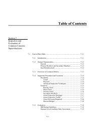
Table <strong>of</strong> Contents<br />
January 18, 2013<br />
100 GENERAL .............................................................................................................................................. 1<br />
101 Introduction (Draft) ................................................................................................................. 1<br />
102 Distribution .............................................................................................................................. 1<br />
103 Revisions and Updates .......................................................................................................... 2<br />
104 Trademarks (Draft) .................................................................................................................. 2<br />
200 <strong>CADD</strong> STANDARDS ............................................................................................................................. 3<br />
201 Installation and Configuration ............................................................................................... 3<br />
201.1 General ..................................................................................................................... 3<br />
201.2 Installation ................................................................................................................. 3<br />
201.3 <strong>CADD</strong> <strong>Standards</strong> Directory ....................................................................................... 3<br />
201.4 Configuration Variables and Files ............................................................................. 4<br />
202 Level Assignments ................................................................................................................. 5<br />
202.1 General ..................................................................................................................... 5<br />
202.2 Level Naming Convention ......................................................................................... 6<br />
202.3 ByLevel Considerations ............................................................................................ 7<br />
202.4 Filters ........................................................................................................................ 8<br />
202.5 Priority and Transparency ....................................................................................... 11<br />
203 Colors ..................................................................................................................................... 18<br />
203.1 General ................................................................................................................... 18<br />
204 Line Styles ............................................................................................................................. 18<br />
204.1 General ................................................................................................................... 18<br />
204.2 Types <strong>of</strong> Line Styles ................................................................................................ 19<br />
204.3 Line Style Scales .................................................................................................... 20<br />
204.4 Plotting .................................................................................................................... 29<br />
205 Line Weights .......................................................................................................................... 30<br />
205.1 General ................................................................................................................... 30<br />
205.2 Plotting .................................................................................................................... 30<br />
206 Cell Libraries ......................................................................................................................... 30<br />
206.1 General ................................................................................................................... 30<br />
206.2 Cell Types ............................................................................................................... 30<br />
206.3 Cell Libraries ........................................................................................................... 31<br />
206.4 Cell Placement ........................................................................................................ 31<br />
207 Fonts ...................................................................................................................................... 42<br />
207.1 General ................................................................................................................... 42<br />
207.2 Text Size ................................................................................................................. 43<br />
207.3 Text Line Spacing ................................................................................................... 43<br />
207.4 Text Styles .............................................................................................................. 44<br />
207.5 Dimension Styles .................................................................................................... 47<br />
208 Seed Files .............................................................................................................................. 49<br />
208.1 General ................................................................................................................... 49<br />
208.2 Models ..................................................................................................................... 49<br />
ODOT <strong>CADD</strong> <strong>Engineering</strong> <strong>Standards</strong> i
January 18, 2013<br />
209 GEOPAK Design and Computation Manager Database .................................................... 50<br />
209.1 General ................................................................................................................... 50<br />
210 GEOPAK Survey Manager Database................................................................................... 50<br />
210.1 General ................................................................................................................... 50<br />
210.2 Survey Field Codes ................................................................................................. 50<br />
210.3 Survey Manager Database ..................................................................................... 50<br />
211 Working Units ........................................................................................................................ 51<br />
211.1 General ................................................................................................................... 51<br />
212 Global Origin ......................................................................................................................... 51<br />
212.1 General ................................................................................................................... 51<br />
213 Custom Applications ............................................................................................................ 52<br />
213.1 General ................................................................................................................... 52<br />
214 GEOPAK Criteria Files .......................................................................................................... 53<br />
214.1 General ................................................................................................................... 53<br />
214.2 Cross Section Criteria Files .................................................................................... 53<br />
214.3 3 PC Criteria Files ................................................................................................... 54<br />
214.4 Cross Section Input Files ........................................................................................ 54<br />
300 FILE MANAGEMENT .......................................................................................................................... 55<br />
301 General ................................................................................................................................... 55<br />
301.1 General ................................................................................................................... 55<br />
302 Project Directory Structure .................................................................................................. 55<br />
302.1 Standard Directory Structure .................................................................................. 55<br />
303 References ............................................................................................................................. 63<br />
303.1 General ................................................................................................................... 63<br />
303.2 Models ..................................................................................................................... 63<br />
303.2.1 Types <strong>of</strong> Models ...................................................................................... 65<br />
303.2.2 Model Names .......................................................................................... 66<br />
303.2.3 Model Properties ..................................................................................... 67<br />
303.2.4 Referencing Models ................................................................................ 69<br />
303.3 Basemap Design Files ............................................................................................ 69<br />
303.4 Sheet Design Files .................................................................................................. 70<br />
304 File Naming Conventions ..................................................................................................... 72<br />
304.1 General ................................................................................................................... 72<br />
304.2 File Extensions ........................................................................................................ 72<br />
304.3 File Name Format ................................................................................................... 73<br />
304.4 Supplemental Description Guidelines ..................................................................... 74<br />
304.5 Assigning Supplemental Descriptions .................................................................... 75<br />
304.6 Viewing Supplemental Descriptions ....................................................................... 76<br />
305 GEOPAK Digital Terrain Models .......................................................................................... 82<br />
305.1 General ................................................................................................................... 82<br />
306 GEOPAK Coordinate Geometry Databases ....................................................................... 82<br />
306.1 General ................................................................................................................... 82<br />
306.2 GEOPAK COGO Element Names .......................................................................... 83<br />
ii ODOT <strong>CADD</strong> <strong>Engineering</strong> <strong>Standards</strong>
January 18, 2013<br />
307 GEOPAK Project Manager ................................................................................................... 86<br />
307.1 General ................................................................................................................... 86<br />
307.2 Setting up a Project for GEOPAK Road ................................................................. 86<br />
307.3 Setting up a Project for GEOPAK Survey ............................................................... 88<br />
400 PLOTTING ........................................................................................................................................... 89<br />
401 General ................................................................................................................................... 89<br />
401.1 General ................................................................................................................... 89<br />
401.2 Plotting .................................................................................................................... 90<br />
401.2.1 Priority ..................................................................................................... 90<br />
401.2.2 Transparency .......................................................................................... 90<br />
401.2.3 Shading ................................................................................................... 91<br />
401.2.4 Masking ................................................................................................... 91<br />
401.2.5 Issues with Pen Tables encountered with V8i plotting: .......................... 91<br />
500 ELECTRONIC SUBMISSIONS ........................................................................................................... 92<br />
501 Information Exchange and Electronic Submissions ......................................................... 92<br />
501.1 General ................................................................................................................... 92<br />
502 File Format ............................................................................................................................. 92<br />
502.1 General ................................................................................................................... 92<br />
502.2 Saved View ............................................................................................................. 93<br />
503 Project Index File .................................................................................................................. 94<br />
503.1 General ................................................................................................................... 94<br />
504 <strong>CADD</strong> File Requirements for Design and Construction .................................................... 95<br />
504.1 General ................................................................................................................... 95<br />
504.2 Horizontal Alignment ASCII Reports ....................................................................... 95<br />
504.3 Vertical Alignment ASCII Reports ........................................................................... 99<br />
504.4 LandXML Reports for Horizontal and Vertical Alignments ................................... 101<br />
504.5 LandXML Reports for Triangle Models ................................................................. 103<br />
504.6 Monumentation Reports ........................................................................................ 104<br />
504.7 Cross Section Staking Reports ............................................................................. 107<br />
504.8 Submission <strong>of</strong> Electronic Files to Central Office ................................................... 110<br />
APPENDIX A – <strong>CADD</strong> Information Table ……………………………………..………………………….1-108<br />
APPENDIX B – Fonts ……………………………………………………………………….…………….....1-2<br />
APPENDIX C – Line Styles ………..…………………………………………………….………………….1-9<br />
APPENDIX C – Cells ………………..…………………………………………………….………………….1-180<br />
APPENDIX D – Cell Origins …………………………………………………………………………………1-36<br />
APPENDIX E – Electronic Submission Checklist ………………………………….……………………1-2<br />
APPENDIX F – Level Scale Factors ………………………………….………………………………..…..1<br />
ODOT <strong>CADD</strong> <strong>Engineering</strong> <strong>Standards</strong> iii
January 18, 2013<br />
This page intentionally left blank.<br />
iv ODOT <strong>CADD</strong> <strong>Engineering</strong> <strong>Standards</strong>
100 GENERAL<br />
101 Introduction<br />
January 18, 2013<br />
Computer-Aided Drafting and Design (<strong>CADD</strong>) is the preferred method <strong>of</strong> preparing plans for the <strong>Ohio</strong><br />
<strong>Department</strong> <strong>of</strong> <strong>Transportation</strong> (ODOT). The requirements presented in this manual ensure that <strong>CADD</strong><br />
files can be used by the entire project team (surveyors, planners, environmentalists, designers, reviewers,<br />
contractors, etc.) throughout all phases <strong>of</strong> project development.<br />
ODOT has adopted MicroStation and GEOPAK as its standard drafting and design s<strong>of</strong>tware packages,<br />
respectively. The standards referenced in this manual have been developed and tested using the<br />
s<strong>of</strong>tware versions listed on the following Web page:<br />
http://www.dot.state.oh.us/Divisions/<strong>Engineering</strong>/<strong>CADD</strong>Mapping/<strong>CADD</strong>/Pages/Support.aspx<br />
Note: All references to V8i are for the V8i SELECTseries 2 version <strong>of</strong> MicroStation and GEOPAK.<br />
ODOT will accept electronic and printed deliverables generated from Autodesk tools.<br />
ODOT will provide no support, standards, documentation, or guidance <strong>of</strong> any kind with respect to design<br />
and delivery using Autodesk tools. All <strong>CADD</strong> related documentation, training, supporting files, and<br />
customization provided by ODOT shall be MicroStation/GEOPAK based only.<br />
The design s<strong>of</strong>tware to be used on a project shall be mutually agreed upon by the district and consultant,<br />
and shall be explicitly stated in the project’s scope. Once the decision has been made to use either<br />
MicroStation/GEOPAK or Autodesk, there shall be no deviation from the agreed upon design package,<br />
and the same one shall be used until the project’s completion.<br />
ODOT will continue to operate internally using MicroStation and GEOPAK only.<br />
The final deliverables <strong>of</strong> an Autodesk designed project in printed or electronic format shall mimic that <strong>of</strong> a<br />
project designed and delivered using MicroStation/GEOPAK. The electronic deliverables for projects<br />
designed using Autodesk tools shall be delivered in the native Autodesk format, and not converted to<br />
MicroStation/GEOPAK format.<br />
This manual supersedes all <strong>CADD</strong> standards previously published in the Bridge Design Manual, the<br />
Right-<strong>of</strong>-Way Manual, and the Location and Design Manual, Volume 3.<br />
This manual is not a textbook and does not exempt the pr<strong>of</strong>essional from performing responsible<br />
engineering and/or surveying. It is intended to provide uniform procedures and standards for<br />
organizations that perform <strong>CADD</strong> related services for ODOT. The pr<strong>of</strong>essional shall have final<br />
responsibility for the accuracy <strong>of</strong> all input and output <strong>of</strong> computer-based applications.<br />
102 Distribution<br />
This manual, in its entirety, may be freely copied and distributed for the purpose <strong>of</strong> providing a consistent<br />
guide to the <strong>CADD</strong> requirements <strong>of</strong> the <strong>Ohio</strong> <strong>Department</strong> <strong>of</strong> <strong>Transportation</strong>. The manual, Standard<br />
<strong>CADD</strong> files and other support files can be downloaded from the ODOT <strong>CADD</strong> <strong>Standards</strong> website at the<br />
following address:<br />
http://www.dot.state.oh.us/Divisions/<strong>Engineering</strong>/<strong>CADD</strong>Mapping/<strong>CADD</strong>/Pages/<strong>CADD</strong>Manual.aspx<br />
ODOT <strong>CADD</strong> <strong>Engineering</strong> <strong>Standards</strong> 1
January 18, 2013<br />
For ODOT <strong>CADD</strong> Users, MicroStation and GEOPAK V8i standard <strong>CADD</strong> files are located on each District<br />
and Central Office <strong>CADD</strong> Server under the ODOTstd\V8istd directory.<br />
103 Revisions and Updates<br />
The Office <strong>of</strong> <strong>CADD</strong> and Mapping Services, <strong>CADD</strong> Section, with input from ODOT’s District Offices and<br />
the consultant and construction community, will develop, and maintain procedures and standards for the<br />
<strong>Department</strong>’s <strong>CADD</strong> related activities. <strong>CADD</strong> Manual holders are encouraged to submit comments and<br />
suggestions for improvements to the manual or ODOT’s <strong>CADD</strong> <strong>Standards</strong>. Any errors found should be<br />
brought to the attention <strong>of</strong> the ODOT Office <strong>of</strong> <strong>CADD</strong> and Mapping Services via the following website:<br />
http://www.dot.state.oh.us/Divisions/<strong>Engineering</strong>/<strong>CADD</strong>Mapping/<strong>CADD</strong>/Pages/suggestions.aspx<br />
The <strong>Ohio</strong> <strong>Department</strong> <strong>of</strong> <strong>Transportation</strong> strives to stay current with state <strong>of</strong> the art trends in the market.<br />
However, impacts on project delivery schedules and the resources necessary to provide future support<br />
for new features must be considered prior to any change.<br />
Updating this manual is intended to be a continuous process and revisions will be issued periodically per<br />
the release dates stated on the Design Reference Resource Center (DRRC) web page at the following<br />
address:<br />
http://www.dot.state.oh.us/drrc/Pages/default.aspx<br />
The DRRC web page also provides the option to subscribe to an email list for notification <strong>of</strong> updates to<br />
ODOT’s Standard <strong>CADD</strong> Files. Once you have subscribed to the ODOT <strong>CADD</strong> <strong>Standards</strong> mailing list, it<br />
is your responsibility to notify ODOT <strong>of</strong> a change <strong>of</strong> email address by unsubscribing your old email<br />
address and re-subscribing using your new email address. See the DRRC web page for instructions on<br />
subscribing and unsubscribing.<br />
Revisions to the manual are noted in red text.<br />
104 Trademarks<br />
MicroStation is a registered trademark <strong>of</strong> Bentley Systems, Incorporated. GEOPAK is a registered<br />
trademark <strong>of</strong> GEOPAK Corporation, now a wholly owned subsidiary <strong>of</strong> Bentley Systems, Incorporated. ©<br />
2012 Bentley Systems, Incorporated.<br />
Autodesk is a registered trademark <strong>of</strong> Autodesk, Incorporated.<br />
Other trade names, computer protocols, and file formats mentioned in this manual are the trademarks <strong>of</strong><br />
their respective owners. In no event will the appearance <strong>of</strong> any graphic, description <strong>of</strong> any graphic,<br />
picture, screen display, or any other method <strong>of</strong> conveying meaning be considered to impair the rights <strong>of</strong><br />
the respective owners.<br />
2 ODOT <strong>CADD</strong> <strong>Engineering</strong> <strong>Standards</strong>
200 <strong>CADD</strong> STANDARDS<br />
201 Installation and Configuration<br />
201.1 General<br />
January 18, 2013<br />
This section outlines the setup for a typical installation <strong>of</strong> MicroStation V8i at ODOT. The configuration<br />
files discussed in this section are available from the ODOT <strong>CADD</strong> <strong>Standards</strong> website.<br />
201.2 Installation<br />
For a typical installation <strong>of</strong> MicroStation V8i SELECTseries 2 at ODOT see the document<br />
ODOT_Config.pdf. This document outlines the setup for a typical installation <strong>of</strong> MicroStation V8i<br />
SELECTseries 2.<br />
The ODOT_Config.pdf file is located in the ODOT\V8istd\config\doc directory or the file can be<br />
downloaded from the ODOT <strong>CADD</strong> <strong>Standards</strong> website.<br />
Note: The department has recently migrated to a Windows 7, 64-bit Operating System environment.<br />
The directory paths for Windows XP and Windows 7 are different. The paths for both Operating<br />
Systems are contained in the ODOT_Config.pdf. In the future only the Windows 7 directories may be<br />
provided.<br />
201.3 <strong>CADD</strong> <strong>Standards</strong> Directory<br />
The configuration and associated files for MicroStation and GEOPAK that are used for plan development<br />
at ODOT are typically stored in a directory tree with the root <strong>of</strong> the tree named “ODOTstd”. This directory<br />
structure is set to i:\ODOTstd for a typical ODOT installation, where “i” is a network drive mapped to the<br />
primary <strong>CADD</strong> file server.<br />
Configuration files and the associated <strong>CADD</strong> standards for specific versions <strong>of</strong> MicroStation are stored in<br />
separate folders beneath the ODOTstd folder as shown below:<br />
• Projects<br />
The Projects directory contains the various project configuration files (.pcf) which are read from<br />
this directory.<br />
• V7std<br />
The V7std directory contains all the <strong>CADD</strong> <strong>Standards</strong> for MicroStation and GEOPAK v7.<br />
• V8istd<br />
The V8istd directory contains all the <strong>CADD</strong> <strong>Standards</strong> for MicroStation and GEOPAK V8i.<br />
ODOT <strong>CADD</strong> <strong>Engineering</strong> <strong>Standards</strong> 3
January 18, 2013<br />
201.4 Configuration Variables and Files<br />
ODOT uses four (4) environment variables, ODOTSTD, V8iSTD, HOMEV8i, and V8iGSTD, to locate files<br />
necessary for the operation <strong>of</strong> MicroStation V8i in a typical ODOT setup.<br />
1. The ODOTSTD variable is used to define the location <strong>of</strong> the root ODOT <strong>CADD</strong> standards folder.<br />
This variable is assigned a value in V8iODOTstandards.cfg.<br />
2. The V8iSTD variable is used to define the location <strong>of</strong> the MicroStation V8i <strong>CADD</strong> standards. This<br />
variable is assigned a value in V8iODOTstandards.cfg.<br />
3. The HOMEV8i variable is defined in the V8iODOTstandards.cfg file to specify the location <strong>of</strong> the<br />
MicroStation User Configuration Files (UCF) and User Preference Files (UPF). The HOMEV8i<br />
variable is defined as a Windows System Environment Variable and set to w:\V8iUser\ for a<br />
typical ODOT setup, where w:\ is connected to a share on a file server.<br />
4. The V8iGSTD variable is used to define the location <strong>of</strong> site specific settings. The primary use <strong>of</strong><br />
this variable is to identify the location <strong>of</strong> Bentley InterPlot (IPLOT) settings files. For a typical<br />
ODOT setup, this variable is defined in ODOTV8i.ucf file as follows: V8iGSTD: i:\V8igstd.<br />
The following ODOT standard configuration files for MicroStation V8i are typically used for plan<br />
development. A brief description <strong>of</strong> each file is included below.<br />
V8iODOTstandards.cfg<br />
This CFG file is used to set the location <strong>of</strong> the Project Configuration Files (PCF), User<br />
Configuration Files (UCF), and User Preference Files (UPF). See the document<br />
ODOT_Config.pdf for the file location.<br />
dfltuser.cfg<br />
This file tells MicroStation what UCF file to use on initial startup.<br />
ODOTV8i.pcf<br />
This PCF file is the Project Configuration File used to set the configuration variables for ODOT’s<br />
MicroStation V8i <strong>CADD</strong> standards stored in the ODOTstd\Projects folder.<br />
ODOTV8i.ucf<br />
This UCF file is the seed User Configuration File for MicroStation V8i. This file is used to define<br />
any user specific configuration variables for MicroStation V8i. This file should be copied to the<br />
location defined by the Variable HOMEV8i.<br />
ODOTV8iSeed.upf<br />
This UPF file is the default seed User Preference File that contains the settings defined in the<br />
MicroStation Preferences dialog.<br />
For further details on the setup and use <strong>of</strong> these configuration files, see MicroStation Configuration Files<br />
download page on the ODOT <strong>CADD</strong> <strong>Standards</strong> website.<br />
4 ODOT <strong>CADD</strong> <strong>Engineering</strong> <strong>Standards</strong>
Alternate Configuration Files<br />
There are alternate configuration files available to ODOT users as described below:<br />
January 18, 2013<br />
• ODOTV7.ucf & ODOTV7.pcf<br />
These configuration files are used to open design files in MicroStation/J (v7) format. This<br />
configuration is intended to be used for viewing, plotting, and making minor edits to old design<br />
files in v7 format. Access to GEOPAK has been disabled in this configuration.<br />
• ODOTV8_JUL07.ucf & ODOTV8_JUL07.pcf<br />
These configuration files are used when viewing or editing MicroStation V8 design files developed<br />
using the Bridge custom line styles with the ODOT <strong>CADD</strong> <strong>Standards</strong> that were in place on or<br />
before July 20, 2007.<br />
In order to use one <strong>of</strong> the alternate ODOT configurations, the .ucf file must be copied to the directory<br />
specified by the variable HOMEV8i.<br />
202 Level Assignments<br />
202.1 General<br />
To maintain uniformity among different drawing files, it is essential that an organized leveling system be<br />
used. MicroStation permits data to be organized in any fashion on an unlimited number <strong>of</strong> drawing levels.<br />
ODOT has developed a standard set <strong>of</strong> levels to be used with all design files submitted to or exchanged<br />
with the <strong>Department</strong>.<br />
ODOT’s standard levels are defined in a MicroStation DGN Library, ODOT_Levels.dgnlib, which can be<br />
obtained from the ODOT <strong>CADD</strong> <strong>Standards</strong> website. The DGN library is attached by use <strong>of</strong> the<br />
MicroStation configuration variable MS_DGNLIBLIST.<br />
Users shall not create their own levels for use in any design files submitted or exchanged with ODOT.<br />
See the <strong>CADD</strong> Information Table, Appendix A, for a complete list <strong>of</strong> the ODOT levels.<br />
ODOT <strong>CADD</strong> <strong>Engineering</strong> <strong>Standards</strong> 5
January 18, 2013<br />
202.2 Level Naming Convention<br />
ODOT level names use the following naming convention:<br />
Classification_Disposition_Logical Name<br />
The Classification consists <strong>of</strong> two (2) uppercase characters used to group the levels into categories.<br />
The Classification names are listed in the table below:<br />
Classification Description<br />
AP Airports<br />
BD Buildings<br />
BR Bridge<br />
CM Corridor Modeler<br />
DR Drainage<br />
DT Digital Terrain Models<br />
DV Divisions<br />
EV Environmental<br />
GE Geometry<br />
GK GEOPAK<br />
GM Geomedia (County Maps)<br />
GT Geotechnical<br />
HY Hydraulics<br />
LT Lighting<br />
MT Maintenance <strong>of</strong> Traffic<br />
PF Pr<strong>of</strong>iles<br />
PM Pavement Marking<br />
PV Pavement<br />
RC Recreational<br />
RD Roadway<br />
RS Raster Files<br />
RW Right-<strong>of</strong>-Way<br />
SC Scratch<br />
SG Signals<br />
SH Sheets<br />
SN Signs<br />
ST Standard Construction Drawings & Plan Insert Sheets<br />
SV Survey<br />
TR Truck Turning Paths<br />
TX Text<br />
UT Utilities<br />
VG Vegetation<br />
XS Cross Sections<br />
The Disposition is used to identify the level for placement <strong>of</strong> either X (existing) or P (proposed)<br />
information.<br />
The Logical Name is used as a description <strong>of</strong> the element contents. Where appropriate, common<br />
industry abbreviations are used.<br />
All ODOT levels names use alphanumeric characters only. No spaces or special characters are used<br />
other than the underscore “_” character.<br />
6 ODOT <strong>CADD</strong> <strong>Engineering</strong> <strong>Standards</strong>
202.3 ByLevel Considerations<br />
January 18, 2013<br />
In general, to facilitate use <strong>of</strong> MicroStation’s ByLevel attributes, the ODOT levels have been established<br />
such that each curvilinear feature will have its own level. In order to keep the overall number <strong>of</strong> levels<br />
manageable, there are cases where similar features will be placed on the same level making it impossible<br />
to use ByLevel attributes for those features. Some exceptions are noted below:<br />
• Standard ODOT cells are placed on the level in which they were created. Each cell is not placed<br />
on its own level, rather, like cells are grouped on one level. For example, existing electric utility<br />
cells are all placed on the level UT_X_Electric_Cells.<br />
• Storm Sewer Lines – Each proposed storm sewer line 12” and above will be placed using the<br />
custom line style stormline, which shall be scaled, based on the pipe size. All proposed storm<br />
sewer lines will be placed on the level DR_P_Storm_Sewer.<br />
• Culvert Lines – Each proposed culvert line will be placed using a custom line style based on the<br />
culvert size. All proposed culvert lines will be placed on the level DR_P_Culvert.<br />
• Maintenance <strong>of</strong> Traffic Drums – Multiple line styles have been created to represent various typical<br />
drum spacing’s. These lines are placed on level MT_P_Drums.<br />
• Centerline Pavement Marking – Multiple line styles and colors are available representing various<br />
centerline pavement markings. These lines are placed on level PM_P_CL (proposed) or<br />
PM_X_CL (existing).<br />
As a general rule, curvilinear design file elements should be placed using ByLevel attributes except in the<br />
cases noted in the <strong>CADD</strong> Information Table Appendix A.<br />
ODOT <strong>CADD</strong> <strong>Engineering</strong> <strong>Standards</strong> 7
January 18, 2013<br />
202.4 Filters<br />
ODOT’s level library, ODOT_Levels.dgnlib, has been configured with a set <strong>of</strong> default level filters that can<br />
be used to control the display <strong>of</strong> levels based on their attributes. Users may add new filters as deemed<br />
necessary to facilitate project development. Users shall not edit or delete the default filters.<br />
The filters included in ODOT_Levels.dgnlib are listed in the table below:<br />
Filter Value Result<br />
Aerial Mapping<br />
Spatial Features<br />
Topo Features<br />
Airport AP*<br />
Bridge BR*<br />
BD_X_Building|"BR_X_SV_Abut"|"BR_X_S<br />
V_Deck_Top"|DR_X_Culvert|DR_X_Headw<br />
all|DT_X_Break_Line|DT_X_TIN_Hull|DT_X<br />
_Void|HY_X_Water_Edge|HY_X_Wetland_<br />
Area|PV_X_Bikeway|PV_X_Curb|PV_X_Dri<br />
veway|PV_X_EOP|PV_X_Field_Drive|"PV_<br />
X_Shoulder"|PV_X_Walk|RD_X_Concrete_<br />
Barrier|RD_X_Fence|RD_X_Gate|RD_X_G<br />
R_Lt|RD_X_GR_Rt|RD_X_Misc_Items|RD_<br />
X_Noise_Wall|RD_X_RR_2|RD_X_Wall|VG<br />
_X_Tree_line_Lt|VG_X_Tree_Line_Rt<br />
BD_X_Building|DT_X_Break_Line|DT_X_TI<br />
N_Hull|DT_X_Void|HY_X_Water_Edge|PV_<br />
X_Curb|PV_X_Driveway|PV_X_EOP|PV_X<br />
_Shoulder|RD_X_RR_2<br />
BR_X_SV_Abut|BR_X_SV_Deck_Top|DR_<br />
X_Culvert|DR_X_Headwall|HY_X_Wetland<br />
_Area|PV_X_Bikeway|PV_X_Field_Drive|P<br />
V_X_Walk|RD_X_Concrete_Barrier|RD_X_<br />
Fence|RD_X_Gate|RD_X_GR_Lt|RD_X_G<br />
R_Rt|RD_X_Misc_Items|RD_X_Noise_Wall<br />
|RD_X_Wall|VG_X_Tree_Line_Lt|VG_X_Tr<br />
ee_Line_Rt<br />
Bridge Beam Beam – SV|BR_*_Gen_Text<br />
Bridge Bearing Brg - SV|BR_*_Gen_Text<br />
Bridge Details<br />
Det – [Beam|Brg|Dia|Rail|<br />
Prestress|Slab] |BR_*_Gen_Text<br />
Bridge Diaphragm Dia - SV|BR_*_Gen_Text<br />
Bridge Drainage Drain|BR_*_Gen_Text<br />
Displays all levels that are used by Aerial<br />
digital mapping.<br />
Displays levels containing the Spatial<br />
features used by Aerial digital mapping.<br />
Displays levels containing the Topo<br />
Features used by Aerial digital mapping.<br />
Displays levels starting with the characters<br />
“AP”.<br />
Displays levels starting with the characters<br />
“BR”.<br />
Displays bridge levels containing “Beam”<br />
except for levels containing “SV” and<br />
contains the levels for the Bridge Generic<br />
Text.<br />
Displays bridge levels containing “Brg”<br />
except for levels containing “SV” and<br />
contains the levels for the Bridge Generic<br />
Text.<br />
Displays bridge levels containing “Det”<br />
except for levels containing “Beam”, “Brg”,<br />
“Dia”, “Rail”, “Prestress” or “Slab” and<br />
contains the levels for the Bridge Generic<br />
Text.<br />
Displays bridge levels containing “Dia”<br />
except for levels containing “SV” and<br />
contains the levels for the Bridge Generic<br />
Text.<br />
Displays bridge levels containing “Drain”<br />
and contains the levels for the Bridge<br />
Generic Text.<br />
8 ODOT <strong>CADD</strong> <strong>Engineering</strong> <strong>Standards</strong>
Bridge General Gen - SV<br />
Bridge Prestress Prestress|BR_*_Gen_Text<br />
Bridge Railing Rail - SV|BR_*_Gen_Text<br />
Bridge Slab<br />
Bridge<br />
Sub_Deep_Foundatio<br />
n<br />
Slab - [Gen|SV]|<br />
BR_*_Gen_Text<br />
Deep - SV|BR_*_Gen_Text<br />
Bridge Sub_Footing Foot - SV|BR_*_Gen_Text<br />
Bridge Substructure<br />
Sub - [Foot|Deep|SV]|<br />
BR_*_Gen_Text<br />
January 18, 2013<br />
Displays bridge levels containing “Gen”<br />
except for levels containing “SV”.<br />
Displays bridge levels containing<br />
“Prestress” and contains the levels for the<br />
Bridge Generic Text.<br />
Displays bridge levels containing “Rail”<br />
except for levels containing “SV” and<br />
contains the levels for the Bridge Generic<br />
Text.<br />
Displays bridge levels containing “Slab”<br />
except for levels containing “Gen” or “SV”<br />
and contains the levels for the Bridge<br />
Generic Text.<br />
Displays bridge levels containing “Deep”<br />
except for levels containing “SV”<br />
Displays bridge levels containing “Foot”<br />
except for levels containing “SV” and<br />
contains the levels for the Bridge Generic<br />
ODOT <strong>CADD</strong> <strong>Engineering</strong> <strong>Standards</strong> 9<br />
Text.<br />
Displays bridge levels containing “Sub”<br />
except for levels containing “Foot” or “Deep”<br />
or “SV” and contains the levels for the<br />
Bridge Generic Text.<br />
Bridge Survey _X_SV Displays bridge levels containing “_X_SV”.<br />
Buildings BD*<br />
Displays levels starting with the characters<br />
“BD”.<br />
Corridor Modeler CM*<br />
Displays levels starting with the characters<br />
“CM”.<br />
Cross Sections XS*<br />
Displays levels starting with the characters<br />
“XS”.<br />
Divisions DV*<br />
Displays levels starting with the characters<br />
“DV”.<br />
Drainage DR*<br />
Displays levels starting with the characters<br />
“DR”.<br />
DTM DT*<br />
Displays levels starting with the characters<br />
“DT”.<br />
Environmental EV*<br />
Displays levels starting with the characters<br />
“EV”.<br />
Existing Levels _X_|GT_Historic<br />
Displays all existing levels containing “X”<br />
and “GT_Historic”.<br />
Geometry GE*<br />
Displays levels starting with the characters<br />
“GE”.<br />
GEOPAK GK*<br />
Displays levels starting with the characters<br />
“GK”.<br />
Geotechnical GT*<br />
Displays levels starting with the characters<br />
“GT”.<br />
Hydraulics HY*<br />
Displays levels starting with the characters<br />
“HY”.<br />
Lighting LT*<br />
Displays levels starting with the characters<br />
“LT”.<br />
MOT MT*<br />
Displays levels starting with the characters<br />
“MT”.<br />
Pavement PV*<br />
Displays levels starting with the characters<br />
“RV”.<br />
Pavement Marking PM*<br />
Displays levels starting with the characters<br />
“PM”.
January 18, 2013<br />
Pr<strong>of</strong>ile PF*<br />
Displays levels starting with the characters<br />
“PF”.<br />
Proposed Levels _P_|GT_Instrumented|GT_Project<br />
Displays all proposed levels containing “P”,<br />
“GT_Instrumented” and “GT_Project”.<br />
Raster RS*<br />
Displays levels starting with the characters<br />
“RS”.<br />
Recreational RC*<br />
Displays levels starting with the characters<br />
“RC”.<br />
Right-<strong>of</strong>-Way RW*<br />
Displays levels starting with the characters<br />
“RW”.<br />
Roadway RD*<br />
Displays levels starting with the characters<br />
“RD”.<br />
Scratch SC*<br />
Displays levels starting with the characters<br />
“SC”.<br />
Sheets SH*<br />
Displays levels starting with the characters<br />
“SH”.<br />
Signals SG*<br />
Displays levels starting with the characters<br />
“SG”.<br />
Signing SN*<br />
Displays levels starting with the characters<br />
“SN”.<br />
Std_Constr_Plan_Ins<br />
ert_Shts<br />
ST*<br />
Displays levels starting with the characters<br />
“ST”.<br />
Survey SV*<br />
Displays levels starting with the characters<br />
“SV”.<br />
Text (Generic) TX*|*Text<br />
Displays levels starting with the characters<br />
“TX” and the levels containing “Text”.<br />
Truck Paths TR*<br />
Displays levels starting with the characters<br />
“TR”.<br />
Used * Displays levels that are currently in use.<br />
Utilities UT*<br />
Displays levels starting with the characters<br />
“UT”.<br />
Vegetation VG*<br />
Displays levels starting with the characters<br />
“VG”.<br />
10 ODOT <strong>CADD</strong> <strong>Engineering</strong> <strong>Standards</strong>
202.5 Priority and Transparency<br />
January 18, 2013<br />
The levels defined in the MicroStation DGN Library, ODOT_Levels.dgnlib, utilize the Element Priority<br />
and Transparency features. The Priority and some Transparency settings have been incorporated in<br />
ODOT <strong>CADD</strong> <strong>Standards</strong> to facilitate the on-screen viewing <strong>of</strong> the plan features. See the <strong>CADD</strong><br />
Information Table Appendix A, for a complete list <strong>of</strong> Priority and Transparency values.<br />
Priority<br />
• Priority<br />
Elements, levels, and references can be assigned a Priority value. Elements with a higher priority<br />
will display on top <strong>of</strong> elements with a lower value.<br />
• Transparency<br />
Dialog boxes, as well as elements, levels, and references can be set with a transparency value.<br />
Transparent elements allow you to see other graphic elements that are “underneath” a<br />
transparent element.<br />
Display priority is a technique for specifying the relative front-to-back order in which 2D elements appear<br />
in a 2D model (only) when they are displayed in a view. Display priority is only useful or necessary for 2D<br />
models, since all elements in 3D models have their own explicit 3D coordinate space. In 3D models,<br />
elements closer to the eye are always drawn in front <strong>of</strong> elements further from the eye so display priority is<br />
not necessary.<br />
The elements with the highest priority values are displayed in front, while the elements with the lowest<br />
priority values are displayed in the back. Values for Element and Level priority may range from -500 to<br />
500.<br />
By default, MicroStation displays the elements on your screen in the order in which they were drawn. If<br />
you're using reference files, the active file will display first followed by the reference files in the order <strong>of</strong><br />
attachment. And finally, if you're using raster reference files, the order is: the raster images first, then the<br />
active file elements, followed by the vector reference files.<br />
Note: Levels for Raster Reference files have been created. The Raster Reference files have<br />
been assigned a low priority value so they will always be displayed behind any existing and<br />
proposed features and references.<br />
ODOT <strong>CADD</strong> <strong>Engineering</strong> <strong>Standards</strong> 11
January 18, 2013<br />
Display priority is not supported in editions prior to MicroStation XM. Files created using display priority<br />
will appear “unsorted” when displayed in previous editions <strong>of</strong> MicroStation V8, or when saved to DGN V7.<br />
In 2D models, you can assign display priority values to references, levels, and to individual elements.<br />
The hierarchy for display priority is reference: level: element. That is:<br />
• All elements in a reference with a higher reference display priority will appear in front <strong>of</strong> all<br />
elements from references with a lower value.<br />
• Within a single model, or from references with the same reference display priority, elements on<br />
levels with higher level display priority will appear in front <strong>of</strong> those with a lower value.<br />
• Where elements have the same reference and level display priority, the element display priority<br />
determines those that will appear in front <strong>of</strong> others.<br />
• Where two elements have the same reference, level, and element display priorities, the one that<br />
appears later in the display order (that is, file position and update sequence) appears on top.<br />
Levels are the main priority differentiator on top <strong>of</strong> which the individual elements <strong>of</strong> a particular level can<br />
be tweaked relative to each other. Priority values have been assigned for each level in the ODOT level<br />
library as shown below.<br />
• Levels for Existing plan features have been assigned a priority value <strong>of</strong> -100.<br />
• Levels for Proposed plan features have been assigned a priority value <strong>of</strong> 100.<br />
• Levels for Existing and Proposed Text have been assigned a priority value <strong>of</strong> 500.<br />
• The level SH_Major_Grid_Line has been assigned a priority value <strong>of</strong> -480.<br />
• The level SH_Minor_Grid_Line has been assigned a priority value <strong>of</strong> -490.<br />
• Levels used for GEOPAK specific features have been assigned various priority values to facilitate<br />
better on-screen viewing <strong>of</strong> the graphics.<br />
• Levels configured for Raster Reference files have been assigned a priority value <strong>of</strong> -500.<br />
With these priority assignments, proposed plan view features will always display on top <strong>of</strong> existing plan<br />
view features regardless <strong>of</strong> the order in which the elements are drawn.<br />
12 ODOT <strong>CADD</strong> <strong>Engineering</strong> <strong>Standards</strong>
January 18, 2013<br />
You do not need to assign a priority value to the elements as they are placed in the design file. The<br />
elements will be displayed according to the priority value that is assigned to the level.<br />
Note: The Active Element Priority value is not a ByLevel setting. When the Active Level is<br />
changed on the Attributes tool bar, the value <strong>of</strong> the Active Element Priority is not set to match<br />
the value assigned to the level.<br />
In the case where two elements are placed on different levels that have the same priority setting, the last<br />
element drawn is displayed on top. This can be changed by assigning a priority value to the element.<br />
Priority values can be assigned when the element is initially placed, or assigned later with the Change<br />
Element Attributes tool.<br />
The priority value assigned to an element is not an “override” <strong>of</strong> the level setting. The priority value<br />
assigned to an individual element is “relative” to the level setting. Behind the scenes, MicroStation uses<br />
an equation (See BE Communites for further details) to determine the “final” priority value <strong>of</strong> the element.<br />
However, most users will be content to know that modifying the priority assigned to an individual element<br />
up or down by increments <strong>of</strong> one (1) will allow them to modify the display priority as needed.<br />
It should be noted that the priority value <strong>of</strong> an element that is reported in the Element Info dialog is the<br />
actual value assigned to the element, not the calculated value.<br />
The priority <strong>of</strong> an element can be modified using the Change Element Attributes tool.<br />
ODOT <strong>CADD</strong> <strong>Engineering</strong> <strong>Standards</strong> 13
January 18, 2013<br />
Priority can also be assigned to Reference files. By default, where a reference is attached it is assigned a<br />
value <strong>of</strong> 0 as shown below.<br />
Values for priority assigned to a reference file can range from -5 to 5.<br />
The hierarchy for display priority is reference: level: element. Therefore, when an element is drawn over<br />
referenced graphics, the reference file will take priority over elements placed in the master design file on<br />
a level that has the same priority value.<br />
All <strong>of</strong> the graphics representing existing features, which are in a reference file, are displayed on top <strong>of</strong> the<br />
shape drawn on the existing building level as shown below.<br />
14 ODOT <strong>CADD</strong> <strong>Engineering</strong> <strong>Standards</strong>
Transparency<br />
January 18, 2013<br />
Transparency can be set for elements, levels, and references. Transparency may vary from 0% to 100%.<br />
A value <strong>of</strong> 0 indicates no transparency at all, while a value <strong>of</strong> 100% indicates almost complete<br />
transparency.<br />
Transparency can be assigned to elements when they are placed by selecting a value from the Attributes<br />
tool bar.<br />
Note: The Active Element Transparency value is not a ByLevel setting. When the Active Level<br />
is changed on the Attributes tool bar, the value <strong>of</strong> the Active Element Transparency is not set to<br />
match the value assigned to the level.<br />
ODOT <strong>CADD</strong> <strong>Engineering</strong> <strong>Standards</strong> 15
January 18, 2013<br />
The Change Element Attributes dialog can be used to set the Transparency values for previously<br />
placed elements.<br />
Just like Priority, when new elements are drawn they take on the Transparency value assigned to the<br />
level. Setting the Active Element Transparency in the Attributes tool box is not an “override”. Behind the<br />
scenes, MicroStation uses an equation (See BE Communites for further details) to determine the “final”<br />
transparency value <strong>of</strong> the element.<br />
16 ODOT <strong>CADD</strong> <strong>Engineering</strong> <strong>Standards</strong>
January 18, 2013<br />
The Transparency value reported in the Element Information dialog box represents the value assigned to<br />
the element and not the “final” transparency value as calculated by MicroStation.<br />
Note: When opening an existing MicroStation V8 design file in XM or V8i, the priority and<br />
transparency values will not be in effect unless an “Update Levels from Library” command is<br />
issued.<br />
ODOT <strong>CADD</strong> <strong>Engineering</strong> <strong>Standards</strong> 17
January 18, 2013<br />
203 Colors<br />
203.1 General<br />
Standard colors are specified to ensure consistency and to enable users to easily identify plan elements<br />
in shared files.<br />
Each element in a MicroStation design file is assigned a color number. MicroStation reads a color table<br />
to determine the correct color to display for the specified number. Standard color numbers for plan<br />
graphics are specified in the <strong>CADD</strong> Information Table, Appendix A.<br />
The ODOT standard color table, ODOT_color.ctb, can be obtained from the ODOT <strong>CADD</strong> <strong>Standards</strong><br />
website. The MicroStation configuration variable MS_DEFCTBL is used to specify the ODOT color table.<br />
The color values may vary or appear different on screen due to the graphics cards, monitors display<br />
capability, etc.<br />
204 Line Styles<br />
204.1 General<br />
Line styles are used to differentiate curvilinear elements in the design file and on the plotted sheet. There<br />
are eight default line styles available in MicroStation using the values zero (0) through seven (7).<br />
Additionally, ODOT has developed a set <strong>of</strong> Custom Line Styles to be used for drawing various plan view<br />
graphic items requiring custom symbology. Custom Line Styles are created as Cosmetic or Physical line<br />
types. For detailed information see Section 204.2 Types <strong>of</strong> Line Styles.<br />
The ODOT standard line style resource file, ODOT_Linestyles.rsc, can be obtained from the ODOT<br />
<strong>CADD</strong> <strong>Standards</strong> website. The MicroStation configuration variable MS_SYMBRSC is used to specify the<br />
custom line style resource file.<br />
Users shall not create their own custom line styles for use on ODOT plan sheets.<br />
Standard line codes and custom line styles for plan graphics are specified in the <strong>CADD</strong> Information Table,<br />
Appendix A and displayed in Appendix D.<br />
18 ODOT <strong>CADD</strong> <strong>Engineering</strong> <strong>Standards</strong>
204.2 Types <strong>of</strong> Line Styles<br />
ODOT <strong>CADD</strong> <strong>Standards</strong> contain two (2) types <strong>of</strong> custom line style definitions:<br />
January 18, 2013<br />
1. “Cosmetic” line styles<br />
Cosmetic line styles are used to represent the location <strong>of</strong> an item, but not the actual size or<br />
spacing <strong>of</strong> the item. A fence line, shown below, is an example <strong>of</strong> a cosmetic custom line style.<br />
• The location <strong>of</strong> the symbols along the custom line style does not represent the actual<br />
location <strong>of</strong> fence posts, and are intended only to designate the line as a fence line.<br />
• Cosmetic line styles are typically placed in the design file at a scale <strong>of</strong> one (1) and then<br />
displayed using the Global Line Style Scale or Annotation Scale factors in the design file at<br />
a scale corresponding to the intended plotting scale <strong>of</strong> the final plans.<br />
2. “Physical” line styles<br />
Physical line styles are used to represent the location <strong>of</strong> an item, and the linear spacing <strong>of</strong> the<br />
components <strong>of</strong> the item. A pavement marking lane line, shown below, which consists <strong>of</strong><br />
alternating 10’ dashes and 30’ gaps, is an example <strong>of</strong> a physical custom line style.<br />
• Physical line styles are always placed in the design file at a scale <strong>of</strong> 1, regardless <strong>of</strong> the<br />
plotting scale.<br />
• Physical line styles are designated as such that the Global Line Style Scale and Annotation<br />
Scale factors when applied are ignored.<br />
Cosmetic and Physical line styles for plan graphics are specified in the <strong>CADD</strong> Information Table,<br />
Appendix A and displayed in Appendix D.<br />
ODOT <strong>CADD</strong> <strong>Engineering</strong> <strong>Standards</strong> 19
January 18, 2013<br />
204.3 Line Style Scales<br />
During the development <strong>of</strong> a set <strong>of</strong> plans, it is common to reference the same basemap design file into<br />
different detail sheet files that may be plotted at different scales. The location and dimensions <strong>of</strong> all plan<br />
view basemap design file information shall be drawn in the default “Design” model using real world<br />
dimensions at a 1:1 scale. Custom Line Styles are to be placed in the basemap at a scale <strong>of</strong> one (1) so<br />
the Model Properties “Line Style Scale” feature can be used.<br />
The Model Properties Line Style Scale feature can be used to control the display size <strong>of</strong> line styles in<br />
the active design file, and in any Reference attachments. This will allow the designer to control the<br />
display size <strong>of</strong> the line styles for any intended plotting scale.<br />
All custom Line Styles should be placed at a scale <strong>of</strong> one (1) and then scaled using the Model<br />
Properties Line Style Scale feature.<br />
20 ODOT <strong>CADD</strong> <strong>Engineering</strong> <strong>Standards</strong>
January 18, 2013<br />
The following details the recommendations for Scaling Custom Line Styles when drafting and designing<br />
ODOT plans using the features available in MicroStation V8i. The final decision regarding plan drafting<br />
and design is at the discretion <strong>of</strong> the designer.<br />
Recommendations for Scaling Custom Line Styles on ODOT plans:<br />
When attaching the basemaps as References into the “Sheet” model, set the Model Properties Line Style<br />
Scale for the appropriate sheet scale. Changing the Model Properties Line Style Scale value will cause<br />
the display <strong>of</strong> the line styles to change according to the value selected. This will affect line styles drawn<br />
in the active file, as well as referenced graphics, depending on the settings when the references were<br />
attached.<br />
Basemap:<br />
Manual Placement (Existing and Proposed):<br />
Place all Line Styles in the basemap design file at a scale <strong>of</strong> one (1.0).<br />
ODOT <strong>CADD</strong> <strong>Engineering</strong> <strong>Standards</strong> 21
January 18, 2013<br />
When working in the basemap, use the following steps to set the Line Style Scale:<br />
In the Model Properties dialog box, set the Line Style Scale using one <strong>of</strong> the following two (2)<br />
methods:<br />
1. From the Line Style Scale drop-down menu, select Annotation Scale to set the line style<br />
scale factor to match the Model Annotation Scale.<br />
Note: This is the recommended procedure for all Roadway Design files.<br />
2. From the Line Style Scale drop-down menu, select Global Line Style Scale to set the line<br />
style scale factor to a value different than the Model Annotation Scale.<br />
22 ODOT <strong>CADD</strong> <strong>Engineering</strong> <strong>Standards</strong>
GEOPAK Placement (Existing and Proposed):<br />
January 18, 2013<br />
The GEOPAK Design and Computation Manager dialog box can be used to place line styles in the<br />
basemap using the default Design mode.<br />
The Design mode is used to plot COGO elements into MicroStation, with the desired symbology, by<br />
use <strong>of</strong> the Draw Plan and Pr<strong>of</strong>ile dialog box. It can also be used to set drafting standards used in<br />
conjunction with MicroStation’s element placement commands, with the Place Influence option<br />
toggled on, as shown below:<br />
When using the Design mode the following procedure is used to place Line Styles in the basemap:<br />
Before you begin placing MicroStation elements in Design Mode, it is good practice to check the<br />
Design Settings to ensure that the Custom Line Style Creation’s Scale Factor value is set<br />
properly.<br />
From the Design and Computation Manager dialog<br />
box, select Settings > Design to access the Design<br />
Settings dialog box shown at right.<br />
ODOT <strong>CADD</strong> <strong>Engineering</strong> <strong>Standards</strong> 23
January 18, 2013<br />
The following options related to Line Style placement are available from or when using the Design<br />
Settings dialog box:<br />
Custom Line Style Creation<br />
The default custom line style Scale Factor to be<br />
used when drawing MicroStation elements is<br />
specified here. For ODOT plans, this value should<br />
be set to one (1.0) as shown right, to allow the Model<br />
Annotation Scale to control the custom line style<br />
scale.<br />
The Annotation Scale is set as follows for Custom Line Styles:<br />
• Select the Models dialog box.<br />
• From the Models dialog box, select Edit Model Properties to access the Model<br />
Properties dialog box as shown below.<br />
• From the Line Style Scale drop-down menu, set the Line Style Scale as desired.<br />
In the example shown right, the<br />
Annotation Scale is set to a value<br />
<strong>of</strong> Engr 1:20. The Line Style<br />
Scale value is set to match the<br />
Annotation Scale.<br />
24 ODOT <strong>CADD</strong> <strong>Engineering</strong> <strong>Standards</strong>
Survey Processing (Existing Basemap):<br />
January 18, 2013<br />
The GEOPAK Project Preferences dialog box is used to control how the line styles in the basemap will<br />
be drawn. To use the Model Properties “Line Style Scale” feature, the field data must be visualized at<br />
a scale <strong>of</strong> one (1.0) as shown below:<br />
The Plot Scale feature is used to control the size <strong>of</strong> the custom line styles used in the mapping <strong>of</strong> the<br />
survey data. The base scale is defined for each feature code in the SMD file. The Plot Scale should<br />
normally be set to a value <strong>of</strong> one (1.0) for all ODOT projects.<br />
Note: For more detailed information on processing the survey data into MicroStation see the<br />
ODOT GEOPAK V8i Survey Training Guide and the ODOT GEOPAK V8i Road 1 Training Guide.<br />
ODOT <strong>CADD</strong> <strong>Engineering</strong> <strong>Standards</strong> 25
January 18, 2013<br />
Sheet Files:<br />
In the “Sheet” model, set the Model Properties Line Style Scale for the appropriate sheet scale.<br />
In the Model Properties dialog box, set the Line Style Scale using one <strong>of</strong> the following two (2)<br />
methods:<br />
1. From the Line Style Scale drop-down menu, select Annotation Scale to set the line style<br />
scale factor <strong>of</strong> the lines styles to match the Model Annotation Scale.<br />
Note: This is the recommended procedure for all Roadway Design files.<br />
2. From the Line Style Scale drop-down menu, select Global Line Style Scale to set the line<br />
style scale factor to a value different than the Model Annotation Scale.<br />
26 ODOT <strong>CADD</strong> <strong>Engineering</strong> <strong>Standards</strong>
January 18, 2013<br />
When attaching References in the “Sheet” model, set the Global LineStyle Scale to Master in the<br />
Reference Attachment Settings dialog box. This will allow the master file to control the scaling <strong>of</strong> line<br />
styles in the active file and all reference attachments.<br />
ODOT <strong>CADD</strong> <strong>Engineering</strong> <strong>Standards</strong> 27
January 18, 2013<br />
Important Notes when Referencing:<br />
• Be aware that if the Line Styles were placed in the basemap using a Scale factor other<br />
than a Scale <strong>of</strong> 1. The referenced line styles are scaled by the Model Properties Line<br />
Style Scale set in the new design file and will appear out <strong>of</strong> scale.<br />
• If the survey data was mapped (visualized) in the basemap for a specific scale, such as<br />
20, set the option “Global Line Style Scale” to Reference in the Reference<br />
Attachment Settings dialog box to match the Annotation Scale value set in the original<br />
reference file.<br />
• If the Model Annotation Scale is already set in the design file and the Model Annotation<br />
Scale is set in the Reference at 1:1, the Detail Scale in the Reference Attachment<br />
Settings dialog box displays the Model Annotation Scale and the Scale (Master:Ref)<br />
displays a 1:1 scale like shown below:<br />
• Be aware if the Model Annotation Scale is already set in the design file and the Model<br />
Annotation Scale is set in the Reference other than 1:1, the Detail Scale in the<br />
Reference Attachment Settings dialog box displays the Reference’s Model Annotation<br />
Scale and the Scale (Master:Ref) is then calculated from the referenced model's<br />
annotation scale and the active model's annotation scale.<br />
For example if the Reference file has a Model Annotation Scale set at 1:20 and the<br />
design file has a Model Annotation Scale set at 1:50 the Detail Scale displays the<br />
Reference’s Model Annotation Scale (1:20) and the Scale (Master:Ref) is calculated<br />
2.5:1 as shown below:<br />
To avoid the Reference from scaling in the design file like shown in the example<br />
above make sure the Scale (Master:Ref) is set to 1:1. If the Scale (Master:Ref) is not<br />
set at 1:1 you will need to change it. Once you have set the Scale to 1:1 the Detail<br />
Scale will then read the design file’s Model Annotation Scale that was set like shown<br />
below:<br />
28 ODOT <strong>CADD</strong> <strong>Engineering</strong> <strong>Standards</strong>
Bridge Design Files:<br />
January 18, 2013<br />
Multiple custom line styles for centerlines have been designated for specific plotting scales (10 scale, 20<br />
scale, 50 scale, etc). Separate levels have been established for the representation <strong>of</strong> these centerlines.<br />
These line styles and levels are specified in the <strong>CADD</strong> Information Table, Appendix A.<br />
Several line styles have been developed specifically for use on Bridge plans that are not always placed at<br />
a specific scale relative to the plotting scale. See Appendix F for suggested Scale factors. The line<br />
styles listed in the table below shall be scaled as necessary to produce a legible detail. These line styles<br />
are assigned to the appropriate level by use <strong>of</strong> ByLevel attributes.<br />
204.4 Plotting<br />
Line Style Name Description<br />
brcllong Centerline Long<br />
brclshort Centerline Short<br />
brconstjoint Construction Joint<br />
brexisting Existing Objects<br />
brhiddenex Hidden Line Existing<br />
brhiddenpr Hidden Line Proposed<br />
brphasepr Phase Construction Line<br />
brbarex Existing Reinforcement Bars<br />
brbarpr Proposed Reinforcement Bars<br />
The dash and gap lengths <strong>of</strong> the MicroStation default line codes 0-7 are defined by the plotting s<strong>of</strong>tware.<br />
See Section 400 for the ODOT plotting values for line codes 0-7.<br />
ODOT <strong>CADD</strong> <strong>Engineering</strong> <strong>Standards</strong> 29
January 18, 2013<br />
205 Line Weights<br />
205.1 General<br />
Line weights are used to differentiate graphical elements in the design file and on the plotted sheet. Line<br />
Weight width ranges from weight 0 (narrowest) to weight 31 (widest) and designate the thickness <strong>of</strong> the<br />
line used to draw or plot a graphic element.<br />
Standard line weights for plan graphics are specified in the <strong>CADD</strong> Information Table, Appendix A.<br />
205.2 Plotting<br />
See Section 400 Plotting for information on line weight plotting thickness values.<br />
206 Cell Libraries<br />
206.1 General<br />
A cell is a complex element composed <strong>of</strong> a group <strong>of</strong> primary elements or other complex elements. Cells<br />
are stored in a cell library. For plan consistency, it is advantageous to create cells for items that will be<br />
repeatedly placed in a design file. Several ODOT standard cell libraries are available as detailed in<br />
Section 206.3 Cell Libraries.<br />
206.2 Cell Types<br />
Most <strong>of</strong> the cells created in ODOT’s cell libraries have been created as graphic cells. The symbology<br />
(color, line style, line weight, and level) <strong>of</strong> a graphic cell is determined when it is created. When graphic<br />
cells are placed, they are level-independent, i.e., they do not rotate with the view and they keep the<br />
settings that were active when they were created. A few cells have been created as point cells where<br />
appropriate. A point cell takes on the active symbology set in the file at the time it is placed and are view<br />
independent, i.e., they rotate with the view.<br />
Several “Pattern and Terminator Type" symbols that were created as graphic type cells in the following<br />
cell libraries are now taking advantage <strong>of</strong> a new feature in MicroStation when placing them in the design<br />
file:<br />
ODOT_Geotech.cel<br />
ODOT_Geotech_1996.cel<br />
ODOT_Symbols.cel<br />
Graphic Cells can be produced on the “Default” Level using specific symbology, such as, color, line style,<br />
and line weight. A benefit to graphic cells being created on the “Default” level is the new symbols act<br />
similar to point cells when placed in the design file they inherit the Active Level, but not the symbology<br />
(color, line style, line weight). It is important to note, that the graphic cell does not inherit the Active<br />
Symbology (i.e. color, weight, line style) like a “Point Cell”, unless the graphic cell was drawn on the<br />
“Default” level with the attributes set to “ByLevel”.<br />
30 ODOT <strong>CADD</strong> <strong>Engineering</strong> <strong>Standards</strong>
206.3 Cell Libraries<br />
January 18, 2013<br />
The following Cell Libraries are available to facilitate the drawing <strong>of</strong> commonly used symbols and sheet<br />
borders as described below:<br />
Cell Library Description<br />
ODOT_Bridge.cel Commonly used cells for Bridge plans.<br />
ODOT_Drainage.cel Cells for standard drainage structures.<br />
ODOT_Geotech.cel Cells used for Geotechnical Information.<br />
ODOT_Geotech_1996.cel Cells used for the Specifications for Subsurface Investigation.<br />
ODOT_RW.cel Commonly used cells for Right-<strong>of</strong>-Way plans.<br />
ODOT_Sheets.cel Cells for standard plan sheet borders.<br />
ODOT_Symbols.cel Cells representing standard plan symbols.<br />
A set <strong>of</strong> cell libraries has been developed to include standard signs from the Office <strong>of</strong> Roadway<br />
<strong>Engineering</strong>, Sign Designs and Markings Manual. These sign cells are easily placed using a custom<br />
application, ODOT_Signs.mvba. A complete list <strong>of</strong> the sign cell libraries and instructions for running the<br />
signs application can be found on the ODOT <strong>CADD</strong> <strong>Standards</strong> website.<br />
The Cell libraries can be accessed from the ODOT <strong>CADD</strong> <strong>Standards</strong> website via the MicroStation<br />
Downloads web page.<br />
206.4 Cell Placement<br />
The ODOT cell libraries have been updated to utilize the new enhancement for Annotation Cells. Every<br />
cell can be placed as an Annotation Cell when the new feature “Can be placed as an annotation cell” is<br />
toggled on in the Model Properties dialog box.<br />
ODOT <strong>CADD</strong> <strong>Engineering</strong> <strong>Standards</strong> 31
January 18, 2013<br />
When you change the active model's Annotation Scale value, annotation cells in the model are<br />
automatically scaled by the new value.<br />
Annotation Scale - sets the scale for Text, Dimensions and Cells in the model. You can select from the<br />
list <strong>of</strong> common scales used for ODOT plan sheets. When placing Text, Dimensions or Cells, the<br />
Annotation Lock must be on to ensure that the text, dimensions and cells are placed at the defined scale.<br />
32 ODOT <strong>CADD</strong> <strong>Engineering</strong> <strong>Standards</strong>
ODOT <strong>CADD</strong> <strong>Standards</strong> contain two (2) types <strong>of</strong> cell definitions:<br />
January 18, 2013<br />
1. “Cosmetic” cells<br />
Cosmetic cells are used to represent the location <strong>of</strong> an object and are intended only to designate<br />
the location not the actual size or dimensions <strong>of</strong> the object. A Mail Box, shown below, is an<br />
example <strong>of</strong> a cosmetic cell.<br />
• Cosmetic cells are typically placed in the design file at a scale <strong>of</strong> one (1) and then displayed<br />
using the Annotation Scale factors in the design file at a scale corresponding to the intended<br />
plotting scale <strong>of</strong> the final plans.<br />
• The ability to place Cosmetic cells using the Annotation Scale Lock has been enabled in<br />
the cell definition by toggling on the Can be placed as annotation cell option.<br />
2. “Physical” cells<br />
Physical cells are used to represent the actual size or dimensions <strong>of</strong> an object. A Catch Basin,<br />
shown below, is an example <strong>of</strong> a physical cell.<br />
• Physical cells are always placed in the design file at a scale <strong>of</strong> 1, regardless <strong>of</strong> the plotting<br />
scale and are designated as such that the Annotation Scale factors when applied are<br />
ignored.<br />
• The ability to place Physical cells using the Annotation Scale Lock has been disabled in the<br />
cell definition.<br />
The Place Active Cell tool is used to place annotation cells. The<br />
tool's settings window has an Annotation Scale Lock icon similar<br />
to the one for the Place Text tool and dimensioning tools. When<br />
you set the Active Cell to a cell that can be placed as an<br />
annotation cell, the Annotation Scale icon should be enabled as<br />
shown right.<br />
The icon's tool tip tells you the active model's annotation scale<br />
factor and the <strong>of</strong>f/on state <strong>of</strong> the Annotation Scale Lock. If this<br />
lock is on, the model's Annotation Scale factor will be applied to<br />
the cell you are placing. To turn on the Annotation Scale Lock,<br />
click the icon.<br />
Note: If the Annotation Scale lock is <strong>of</strong>f when placing cells<br />
in the design file the Annotation Scale feature is ignored.<br />
Cosmetic and Physical cells for plan graphics are specified in the <strong>CADD</strong> Information Table, Appendix A<br />
and displayed in Appendix C along with the Cell Origins.<br />
ODOT <strong>CADD</strong> <strong>Engineering</strong> <strong>Standards</strong> 33
January 18, 2013<br />
Recommendations for Scaling Cells on ODOT plans:<br />
Basemap design files are used to draw existing and proposed plan view information for the entire length<br />
<strong>of</strong> the project for both Roadway and Bridge projects. All basemap information shall be drawn in the<br />
default Design model. The location and dimensions <strong>of</strong> all plan view basemap design file information shall<br />
be drawn using real world dimensions at a 1:1 scale. Cells are to be placed in the basemap at a scale <strong>of</strong><br />
one (1), with the Place Active Cell’s Annotation Scale Lock toggled on so the Model Properties<br />
Annotation Scale feature can be used.<br />
When attaching the basemaps as References to the “Sheet” model, set the Model Properties<br />
Annotation Scale for the appropriate sheet scale. Changing the Model Properties Annotation Scale<br />
value will cause the display <strong>of</strong> the Cells to change according to the value selected. This will affect cells,<br />
text and dimensions drawn in the active file, as well as referenced graphics depending on the settings<br />
when the references were attached.<br />
All cells should be placed at a scale <strong>of</strong> one (1) with the Place Active Cell’s Annotation Scale Lock<br />
toggled on and then scaled using the Model Properties Annotation Scale as shown below.<br />
34 ODOT <strong>CADD</strong> <strong>Engineering</strong> <strong>Standards</strong>
January 18, 2013<br />
The following procedures listed are based on the expanded features available in MicroStation. The final<br />
decision regarding plan drafting and design is at the discretion <strong>of</strong> the designer.<br />
Basemap:<br />
Manual Placement (Existing and Proposed):<br />
Place all Cells in the basemap design file at a Scale <strong>of</strong> one (1.0) with the Place Active Cell<br />
Annotation Scale Lock toggled on.<br />
When working in the basemap, use the following procedure to set the Annotation Scale:<br />
In the Model Properties dialog box, set the Annotation Scale to the appropriate <strong>Engineering</strong><br />
Scale desired.<br />
ODOT <strong>CADD</strong> <strong>Engineering</strong> <strong>Standards</strong> 35
January 18, 2013<br />
GEOPAK Placement (Existing and Proposed):<br />
The GEOPAK Design and Computation Manager dialog box can be used to place cells in the<br />
basemap using the default Design mode.<br />
The Design mode is used to plot COGO elements into MicroStation with the desired symbology by<br />
use <strong>of</strong> the Draw Plan and Pr<strong>of</strong>ile dialog box. It can also be used to set drafting standards to be used<br />
in conjunction with MicroStation’s element placement commands, with the Place Influence option<br />
toggled on as shown below.<br />
When using the Design mode, the following procedure should be used to place Cells in the base<br />
map:<br />
Before you begin placing MicroStation elements in<br />
Design Mode, it is good practice to check the Design<br />
Settings to ensure that the Cell Creation’s Plot Scale<br />
value is set properly.<br />
From the Design and Computation Manager dialog<br />
box, select Settings > Design to access the Design<br />
Settings dialog box shown at right.<br />
36 ODOT <strong>CADD</strong> <strong>Engineering</strong> <strong>Standards</strong>
January 18, 2013<br />
The following options related to Cell placement are available from or when using the Design Settings<br />
dialog box:<br />
Cell Creation<br />
The default Plot Scale factor for placing cells is specified here. For ODOT plans, this value should<br />
be set to one (1.0) to allow the Model Annotation Scale to control the cell scale.<br />
Influence Graphic Cell Level Symbology<br />
When active, the Influence Graphic Cell Symbology uses the symbology within the Design and<br />
Computation Manager, ignoring the element symbology used when the cell was created. This option<br />
should always be toggled <strong>of</strong>f for ODOT plans.<br />
ODOT <strong>CADD</strong> <strong>Engineering</strong> <strong>Standards</strong> 37
January 18, 2013<br />
The Annotation Scale is set as follows for Cells:<br />
• Select the Models dialog box.<br />
• From the Models dialog box, select Edit Model Properties to access the Model<br />
Properties dialog box as shown below.<br />
• Set the Annotation Scale as<br />
desired.<br />
In the example shown at right, the Annotation<br />
Scale is set to a value <strong>of</strong> Engr 1:20, with the<br />
Line Style Scale value set to match the<br />
Annotation Scale.<br />
Notes:<br />
• The method described above is a change in procedure from previous MicroStation<br />
releases.<br />
• The ODOT Design & Computation Manager Database for GEOPAK V8i has been<br />
specifically modified to accommodate placing cells using the Model Annotation Scale.<br />
Previous versions <strong>of</strong> ODOT.ddb will not allow the cells to be scaled using the Annotation<br />
Scale.<br />
38 ODOT <strong>CADD</strong> <strong>Engineering</strong> <strong>Standards</strong>
Survey Processing (Existing Basemap):<br />
January 18, 2013<br />
The GEOPAK Project Preferences dialog box is used to control how the Cells in the basemap will<br />
be drawn. To use the Model Properties “Annotation Scale” feature, the Cells must be visualized at<br />
a scale <strong>of</strong> one (1.0) as shown below:<br />
The Plot Scale item is used to control the size <strong>of</strong> the Cells, and Text used in the mapping <strong>of</strong> the<br />
survey data. The base scale is defined for each feature code in the SMD file. The Plot Scale should<br />
normally be set to a value <strong>of</strong> one 1.0 for all ODOT projects.<br />
Text and cells placed by GEOPAK Survey are not automatically scaled until the annotation scale is<br />
manually applied to the survey mapping.<br />
To apply the model annotation scale to the Cells and Text, type the command Annotationscale Add<br />
into the Key-in window inside MicroStation as shown below:<br />
This command will apply the annotation scale to all the cells and text in the model. The cells and text<br />
will now take on the active model annotation scale value.<br />
After the annotation scale has been applied to the cells and text in the file by use <strong>of</strong> the<br />
Annotationscale Add command, you do not need to run the key-in command again for the cells and<br />
text to honor changes to the model annotation scale.<br />
ODOT <strong>CADD</strong> <strong>Engineering</strong> <strong>Standards</strong> 39
January 18, 2013<br />
Sheet Files:<br />
Important Survey Processing Notes:<br />
• If additional survey data is mapped to the same design file, it will be necessary to run the<br />
key-in Annotationscale Add command again in order for the new data to honor the<br />
current annotation scale value.<br />
• The display <strong>of</strong> the text, cell, and line styles can be controlled uniquely for reference<br />
attachments. For example, the Survey Basemap file can be set with the model<br />
annotation scale value necessary for the Surveyor. Designers may reference the file and<br />
set the model annotation scale for a different value as needed for the plans without<br />
altering the survey basemap.<br />
• The Annotationscale Add command will optionally work with a MicroStation selection set.<br />
If no elements are selected when the command is processed, all cells and text in the<br />
active model will be processed.<br />
• Care must be taken to ensure that elements other than the survey information are not<br />
selected when the Annotationscale Add command is applied. For example, the text for<br />
centerline stationing and curve data that is placed by the GEOPAK Design and<br />
Computation Manager is placed for a specific plotting scale (this procedure will not<br />
change). If you apply the Annotationscale Add command to these elements, they will<br />
appear out <strong>of</strong> scale when the command is applied since they were not originally placed at<br />
a scale <strong>of</strong> one (1).<br />
In the “Sheet” model, set the Model Properties Annotation Scale for the appropriate sheet scale.<br />
40 ODOT <strong>CADD</strong> <strong>Engineering</strong> <strong>Standards</strong>
January 18, 2013<br />
Changing the Annotation Scale value will cause the display <strong>of</strong> the Text, Cells and Dimensions to change<br />
according to the value selected. This will affect elements drawn in the active file, as well as Referenced<br />
graphics, depending on the settings when the references were attached.<br />
Important Notes when Referencing:<br />
• Be aware that if the Cells were placed in the basemap using a Scale factor other than a<br />
Scale <strong>of</strong> 1, with the Cell Annotation Scale Lock on, the referenced cells will be scaled by<br />
the Model Annotation Scale set in the new dgn file and will appear out <strong>of</strong> scale.<br />
• If the Model Annotation Scale is already set in the design file and the Model Annotation<br />
Scale is set in the Reference at 1:1, the Detail Scale in the Reference Attachment<br />
Settings dialog box displays the Model Annotation Scale and the Scale (Master:Ref)<br />
displays a 1:1 scale like shown below:<br />
• Be aware if the Model Annotation Scale is already set in the design file and the Model<br />
Annotation Scale is set in the Reference other than 1:1, the Detail Scale in the<br />
Reference Attachment Settings dialog box displays the Reference’s Model Annotation<br />
Scale and the Scale (Master:Ref) is then calculated from the referenced model's<br />
annotation scale and the active model's annotation scale.<br />
For example if the Reference file has a Model Annotation Scale set at 1:20 and the<br />
design file has a Model Annotation Scale set at 1:50 the Detail Scale displays the<br />
Reference’s Model Annotation Scale (1:20) and the Scale (Master:Ref) is calculated<br />
2.5:1 as shown below:<br />
To avoid the Reference from scaling in the design file like shown in the example<br />
above make sure the Scale (Master:Ref) is set to 1:1. If the Scale (Master:Ref) is not<br />
set at 1:1 you will need to change it. Once you have set the Scale to 1:1 the Detail<br />
Scale will then read the design file’s Model Annotation Scale that was set like shown<br />
below:<br />
ODOT <strong>CADD</strong> <strong>Engineering</strong> <strong>Standards</strong> 41
January 18, 2013<br />
207 Fonts<br />
207.1 General<br />
ODOT has defined several standard fonts for use on all plans. It is important to use these fonts so that<br />
the final plotted version matches the electronic version <strong>of</strong> the file. Only the fonts provided by ODOT (30,<br />
31, 57, and 70) are acceptable for use on ODOT plans. True Type fonts shall not be used on ODOT<br />
Construction plans.<br />
The ODOT standard font resource file, ODOT_Fonts.rsc, can be obtained from the ODOT <strong>CADD</strong><br />
<strong>Standards</strong> website. The MicroStation configuration variable MS_FONTPATH is used to specify the font<br />
library.<br />
The following fonts are available in the ODOT standard font resource file, ODOT_Fonts.rsc:<br />
Font 30 - Straight, proportional characters with uppercase, lowercase, and fractions. This font is<br />
for general plan use and has the modified keystrokes set.<br />
Font 31 - Slanted, proportional characters with uppercase, lowercase, and fractions. This font is<br />
for general plan use and has the modified keystrokes set.<br />
Font 57 – Straight, proportional characters with the Greek alphabet in upper and lowercase.<br />
Font 70 - Block filled. This font is used on plan sheets when a bold title is necessary.<br />
Modified keystrokes are used to generate certain symbols and special characters for Font 30 and Font 31<br />
as shown in Appendix B. Font 57 and Font 70 are also shown for reference.<br />
All text placed on Bridge sheets, excluding text contained in standard border cells, shall use Font 31.<br />
All text placed on Geotechnical Exploration sheets, excluding text contained in standard border cells,<br />
shall use Font 30 or Font 31. For purposes <strong>of</strong> this manual, the term “Geotechnical Exploration sheets”<br />
shall apply to all sheets generated per the Specifications for Subsurface Investigations (SSI) or the<br />
Specifications for Geotechnical Explorations (SGE).<br />
42 ODOT <strong>CADD</strong> <strong>Engineering</strong> <strong>Standards</strong>
207.2 Text Size<br />
January 18, 2013<br />
Standard text sizes have been defined to ensure uniform legibility <strong>of</strong> all plan sheets. Standard text size<br />
refers to the size <strong>of</strong> the text on the finished plot, not the text size in the design file. The correct design file<br />
text size is dependent upon the intended plot scale. ODOT standard text sizes for the finished plot scale<br />
are shown in the following table:<br />
Text Type Plotted Text Size<br />
Normal 0.14”<br />
Subtitle 0.17”<br />
Title 0.20”<br />
Main Title 0.25”<br />
To calculate text size used in a MicroStation design file for various scaled plan sheets use this method:<br />
(Text Size) x (Plotting Scale) = Design File Text Size<br />
Example: 0.14 inch x 20 feet/inch = 2.8 feet<br />
Text sizes smaller than the Normal text size are not acceptable.<br />
For all Roadway plan sheets and Geotechnical Exploration sheets, the preferred method to set the text<br />
size is by use <strong>of</strong> the Model Annotation Scale parameter. See section 207.4 Text Styles for more<br />
information.<br />
Text placed in the sheet model for bridge detail sheets should normally be placed at a scale <strong>of</strong> 1. For<br />
more information on the use <strong>of</strong> design models and sheet models, see section 303 References.<br />
207.3 Text Line Spacing<br />
In general, Text Line Spacing should be one-half (0.50”) the text height. The spacing between lines on<br />
summary, sub-summary, general note sheets and charts is generally equal to the minimum text size.<br />
Note: If needed it is permissible to use Text Line Spacing equal to the minimum text size.<br />
Text Line Spacing distances is now relative to the Text Height. In the previous versions <strong>of</strong> MicroStation<br />
these distances were an absolute value in master units. If the text height changed dramatically, the<br />
spacing could become inappropriate. Now, if the text height changes the spacing adjusts relative to the<br />
change in the text height. The Text Line Spacing is now a factor <strong>of</strong> the Text Height.<br />
For example with the scale factor set at 0.50” (one-half) the Line Spacing for ODOT’s Text Styles would<br />
be as follows:<br />
Normal Text Size 0.14” x Line Spacing 0.50” = a Line Spacing <strong>of</strong> 0.07”<br />
Sub-Title Text Size 0.17” x Line Spacing 0.50” = a Line Spacing <strong>of</strong> 0.085”<br />
Title Text Size 0.20” x Line Spacing 0.50” = a Line Spacing <strong>of</strong> 0.10”<br />
Main Title Text Size 0.25” x Line Spacing 0.50” = a Line Spacing <strong>of</strong> 0.125”<br />
ODOT <strong>CADD</strong> <strong>Engineering</strong> <strong>Standards</strong> 43
January 18, 2013<br />
207.4 Text Styles<br />
A MicroStation Text Style is a saved set <strong>of</strong> text parameters such as font type, text width, text height, color,<br />
etc. Text styles enable you to place text in a consistent and automated manner. ODOT’s standard text<br />
styles are defined in a MicroStation DGN Library, ODOT_Styles.dgnlib, which can be obtained from the<br />
ODOT <strong>CADD</strong> <strong>Standards</strong> website. This file is attached for use by the MicroStation configuration variable<br />
MS_DGNLIB.<br />
The following Text Styles have been configured for use on ODOT plans:<br />
Style Name *Text Size *Line Spacing Font<br />
Font 70-Main Title 0.25 0.50 70<br />
Font 70-Title 0.20 0.50 70<br />
Font 70-Sub Title 0.17 0.50 70<br />
Masked Slanted-Normal LS=0.50 0.14 0.50 31<br />
Masked Straight-Normal LS=0.50 0.14 0.50 30<br />
Slanted-Normal FX Spacing 0.14 0.50 31<br />
Slanted-Normal LS=0.50 0.14 0.50 31<br />
Slanted-Normal LS=0.75 0.14 0.75 31<br />
Slanted-Normal LS=1.00 0.14 1.00 31<br />
Slanted-Sub Title 0.17 0.50 31<br />
Slanted-Title 0.20 0.50 31<br />
Straight-Normal FX Spacing 0.14 0.50 30<br />
Straight-Normal LS=0.50 0.14 0.50 30<br />
Straight-Normal LS=0.75 0.14 0.75 30<br />
Straight-Normal LS=1.00 0.14 1.00 30<br />
Straight-Sub Title 0.17 0.50 30<br />
Straight-Title 0.20 0.50 30<br />
*Text size and Line Spacing units are “inches”.<br />
All text placed on Bridge sheets, excluding text contained in standard border cells, shall use the “Slanted”<br />
text styles.<br />
The active text style can be selected in MicroStation prior to<br />
placing text. Select the Place Text command to access the<br />
following dialog box shown at right.<br />
44 ODOT <strong>CADD</strong> <strong>Engineering</strong> <strong>Standards</strong>
January 18, 2013<br />
Selecting a Text Style will set the text size appropriate for a 1:1 plot. To place text for other plotting<br />
scales, users can automatically set the text size by setting the MicroStation Model Annotation Scale<br />
before placing the text. From the MicroStation pull-down menu, select File > Models or select the<br />
Models icon on the Primary Tools box, then select Edit Model Properties from the Models dialog box to<br />
access the dialog shown below.<br />
The list <strong>of</strong> available annotation scales is defined in the ODOT Standard file ODOT_scales.def which can<br />
be obtained from the ODOT <strong>CADD</strong> <strong>Standards</strong> Website. The MicroStation configuration variable<br />
MS_CUSTOMSCALEDEF is used to assign the scale definition file.<br />
ODOT <strong>CADD</strong> <strong>Engineering</strong> <strong>Standards</strong> 45
January 18, 2013<br />
The following annotation scales have been defined in ODOT_scales.def:<br />
<strong>Engineering</strong> Scales<br />
Architectural Scales<br />
Name Scale Name Scale<br />
Engr 1:1 1:1 Arch 12"=1'-0" 1:12<br />
Engr 1:2 2:1 Arch 6"=1'-0" 1:6<br />
Engr 1:3 3:1 Arch 3"=1'-0" 1:3<br />
Engr 1:4 4:1 Arch 1 1/2"=1'-0" 2:3<br />
Engr 1:5 5:1 Arch 1"=1'-0" 1:1<br />
Engr 1:6 6:1 Arch 3/4"=1'-0" 4:3<br />
Engr 1:8 8:1 Arch 1/2"=1'-0" 2:1<br />
Engr 1:10 10:1 Arch 3/8"=1'-0" 8:3<br />
Engr 1:20 20:1 Arch 1/4"=1'-0" 4:1<br />
Engr 1:25 25:1 Arch 3/16"=1'-0 16:3<br />
Engr 1:30 30:1 Arch 1/8"=1'-0" 8:1<br />
Engr 1:40 40:1 Arch 1/16"=1'-0" 16:1<br />
Engr 1:50 50:1 Arch 1/32"=1'-0" 32:1<br />
Engr 1:100 100:1<br />
Engr 1:200 200:1<br />
Engr 1:250 250:1<br />
Engr 1:400 400:1<br />
Engr 1:500 500:1<br />
Engr 1:1000 1000:1<br />
Engr 1:2000 2000:1<br />
Engr 1:5000 5000:1<br />
Engr 1:10,000 10,000:1<br />
Engr 1:25,000 25,000:1<br />
Engr 1:50,000 50,000:1<br />
Engr 1:100,000 100,000:1<br />
Engr 1:250,000 250,000:1<br />
Architectural scales are used for annotating bridge details when the text is placed in the design model<br />
instead <strong>of</strong> the sheet model.<br />
<strong>Engineering</strong> scales should be used for all Roadway sheets including the Bridge Site Plan sheet and<br />
Geotechnical Exploration sheets.<br />
See the Location and Design Manual, Volume 3 – Roadway Design, the Bridge Design Manual, and the<br />
Specifications for Geotechnical Explorations (SGE) for recommended sheet scales.<br />
46 ODOT <strong>CADD</strong> <strong>Engineering</strong> <strong>Standards</strong>
January 18, 2013<br />
In order to apply the annotation scale to a Text Style, you must toggle on the Annotation Scale Lock in<br />
the Place Text dialog box before placing the text. Select the Place Text command to access the dialog<br />
box shown below.<br />
In the example above, the ODOT, standard text style Slanted-Normal LS=0.50 has been selected with<br />
the Model annotation scale set to Engr 1:20. The text size and line spacing will be set as follows:<br />
Text Size: 0.14 inch x 20 feet/inch = 2.8 feet<br />
Line Spacing: 0.50 inch x 2.8 feet = 1.4 feet<br />
(Line Spacing is set to half the Text size)<br />
Text Styles do not set the Level or Weight for the text placement. The text will be placed on the active<br />
level with the active weight. All text placed using Text Styles established for Title and Sub-Title text<br />
should be placed at a weight <strong>of</strong> 2.<br />
207.5 Dimension Styles<br />
Similar to Text Styles, a MicroStation Dimension Style is a saved set <strong>of</strong> dimensioning parameters. ODOT<br />
has configured a set <strong>of</strong> dimension styles to be used on ODOT plans. These styles are defined in the<br />
ODOT Standard DGN Library, ODOT_Styles.dgnlib, which can be obtained from the ODOT <strong>CADD</strong><br />
<strong>Standards</strong> website. This file is attached or used by the MicroStation configuration variable MS_DGNLIB.<br />
ODOT <strong>CADD</strong> <strong>Engineering</strong> <strong>Standards</strong> 47
January 18, 2013<br />
The following dimension styles have been defined in ODOT_Styles.dgnlib:<br />
Dimension Style Font *Text Size Description<br />
Dec-0, Slanted 31 0.14 Decimal Feet, No decimal places<br />
Dec-0, Straight 30 0.14 Decimal Feet, No decimal places<br />
Dec-1, Slanted 31 0.14 Decimal Feet, 1 decimal place<br />
Dec-1, Straight 30 0.14 Decimal Feet, 1 decimal place<br />
Dec-2, Slanted 31 0.14 Decimal Feet, 2 decimal places<br />
Dec-2, Straight 30 0.14 Decimal Feet, 2 decimal places<br />
Dec-Multiline, Slanted 31 0.14 Decimal Feet, 0.01 accuracy<br />
Dec-Multiline, Straight 30 0.14 Decimal Feet, 0.01 accuracy<br />
Fract-Multiline, Slanted 31 0.14 Fractions, 1/16” accuracy<br />
Fract, Slanted 31 0.14 Fractions, 1/16” accuracy<br />
Masked Fract, Slanted 31 0.14 Fractions, 1/16” accuracy<br />
Masked Fract-Multiline, Slanted 31 0.14 Fractions, 1/16” accuracy<br />
*Text size units are “inches”.<br />
Line Terminators shall be a filled arrow created with a width to height ratio <strong>of</strong> 2.5:1. The terminator width<br />
shall equal the text height.<br />
Leader Lines may be broken when crossing dimension lines. In order to keep broken lines to a minimum,<br />
it is recommended that the user relocate the dimension callout or reposition the dimension. Leader lines<br />
and terminators shall be a weight <strong>of</strong> zero (0) and shall be placed on the same level as required for text<br />
notes and callouts.<br />
Similar to Text Styles, the text size for Dimension Styles can be set by use <strong>of</strong> the Model Annotation Scale<br />
parameter. See section 207.4 Text Styles for more information.<br />
The Multiline dimension styles have been configured to place dimension text above and below the<br />
dimension line as shown at left in the example below. These Dimension styles have been provided to<br />
allow the user to edit the dimension text to contain a label as part <strong>of</strong> the dimension element. This is<br />
advantageous in the case where the dimension is moved or modified since the text is part <strong>of</strong> the<br />
dimension and not a separate text string that must be moved manually. The MicroStation Edit Text<br />
command is used to edit the dimension text. An example <strong>of</strong> the edited text is shown at right below.<br />
Bridge plans shall use the “Fract, Slanted”, “Fract-Multiline, Slanted” or “Masked Fract, Slanted”,<br />
“Masked Fract-Multiline, Slanted” dimension styles. All Bridge dimensions shall be placed associated.<br />
Dimensions shall not have their status dropped.<br />
48 ODOT <strong>CADD</strong> <strong>Engineering</strong> <strong>Standards</strong>
208 Seed Files<br />
208.1 General<br />
January 18, 2013<br />
MicroStation uses a “seed file” to create all design files. A seed file is a template in which standard<br />
parameters are set. Seed files do not typically contain elements, but like other design files they do<br />
contain settings like working units and view configurations. Using a standard, customized seed file helps<br />
maintain uniformity and keeps the user from having to adjust design file settings each time a file is<br />
created.<br />
The following two-dimensional (2D) and three dimensional (3D) seed files are available on the ODOT<br />
<strong>CADD</strong> <strong>Standards</strong> website:<br />
Dimension Seed File Name<br />
2D ODOTSeed2d.dgn<br />
3D ODOTSeed3d.dgn<br />
The MicroStation configuration variable MS_DESIGNSEED is used to define the default seed file.<br />
208.2 Models<br />
ODOT’s seed files each contain two models as listed in the table below.<br />
Model Name Type<br />
Design Design Model<br />
Sheet Sheet Model<br />
For more information on the use <strong>of</strong> models, see section 303 References.<br />
ODOT <strong>CADD</strong> <strong>Engineering</strong> <strong>Standards</strong> 49
January 18, 2013<br />
209 GEOPAK Design and Computation Manager Database<br />
209.1 General<br />
The primary purpose <strong>of</strong> the GEOPAK Design and Computation Manager (D&C Manager) is to assist the<br />
user with the placement <strong>of</strong> MicroStation elements according to a set <strong>of</strong> predefined <strong>CADD</strong> standards.<br />
ODOT provides a standard D&C Manger database, ODOT.ddb that has been configured according to the<br />
<strong>CADD</strong> standards outlined in this manual. The ODOT.ddb can be obtained from the ODOT <strong>CADD</strong><br />
<strong>Standards</strong> website.<br />
The D&C Manager can be used to facilitate the placement <strong>of</strong> curvilinear features or point features<br />
represented by cells according to ODOT standards. For more information on the use <strong>of</strong> the GEOPAK<br />
Design and Computation Manager, see the ODOT GEOPAK Road 1 Training Guide on the ODOT<br />
<strong>CADD</strong> <strong>Standards</strong> website.<br />
Users are not permitted to edit the ODOT.ddb.<br />
210 GEOPAK Survey Manager Database<br />
210.1 General<br />
The GEOPAK Survey Manager Database is primarily used to assist the user with mapping field survey<br />
codes to the appropriate MicroStation symbology according to a predefined set <strong>of</strong> <strong>CADD</strong> <strong>Standards</strong> and<br />
Survey field codes.<br />
210.2 Survey Field Codes<br />
ODOT has developed a set <strong>of</strong> standardized field codes for all survey data submitted to the <strong>Department</strong>.<br />
The list <strong>of</strong> standard field codes for ODOT projects can be obtained from the ODOT <strong>CADD</strong> <strong>Standards</strong><br />
website.<br />
Users are not permitted to use other field codes to supplement the ODOT code list for any project related<br />
survey data submitted to or exchanged with ODOT.<br />
210.3 Survey Manager Database<br />
ODOT has developed a standard Survey Manager Database, ODOT.smd, for use with GEOPAK Survey<br />
S<strong>of</strong>tware to map the field codes contained within a set <strong>of</strong> survey data to the appropriate symbology in a<br />
MicroStation design file according to the <strong>CADD</strong> <strong>Standards</strong> set forth within this manual. The ODOT.smd<br />
can be obtained from the ODOT <strong>CADD</strong> <strong>Standards</strong> website.<br />
Users are not permitted to edit ODOT.smd.<br />
50 ODOT <strong>CADD</strong> <strong>Engineering</strong> <strong>Standards</strong>
211 Working Units<br />
211.1 General<br />
January 18, 2013<br />
MicroStation lets you draw in "real world" units; feet, inches, meters, etc. These real world units are<br />
called working units. Working units are expressed as Master Units (the largest units in common use in a<br />
design file, such as feet) and fractional Sub Units (such as inches).<br />
The default definition for a foot in MicroStation is the International Foot. The U.S. Survey Foot definition<br />
can be defined by use <strong>of</strong> a unit definition file. ODOT has developed a standard unit definition file,<br />
ODOT_Units.def, to define the U.S. Survey Foot as the standard Master Unit. This file can be obtained<br />
from the ODOT <strong>CADD</strong> <strong>Standards</strong> website. The active unit definition file is specified by the configuration<br />
variable MS_CUSTOMUNITDEF.<br />
MicroStation design files used in plan preparation shall use the following standard working units as<br />
defined in the ODOT seed files and in ODOT_Units.def:<br />
Unit Names Label<br />
Master Unit: Survey Feet ‘<br />
Sub Unit: Inches “<br />
The ODOT seed files have been defined with a standard resolution setting <strong>of</strong> 12000 per Survey Foot.<br />
This setting shall not be changed by the user.<br />
ODOT’s seed files are set up with the standard working units described above. Deviation from these<br />
working units is not permitted.<br />
212 Global Origin<br />
212.1 General<br />
Elements in the design file are drawn by placing data points. Each data point placed in the design plane<br />
has associated X (easting), Y (northing) and Z (elevation, 3D files only) positions or coordinates. The<br />
design plane is simply a Cartesian coordinate system upon which your design model lies.<br />
In the ODOT Seed files, the point called the Global Origin is set to the design plane's exact center<br />
(178,956.9707, 178,956.9707) and assigned the coordinates 0,0 (2D files) and 0,0,0 (3D files).<br />
The Global Origin is defined in ODOT’s Seed Files and should never be changed for ODOT projects.<br />
ODOT <strong>CADD</strong> <strong>Engineering</strong> <strong>Standards</strong> 51
January 18, 2013<br />
213 Custom Applications<br />
213.1 General<br />
ODOT has written several programs to assist the user with specific <strong>CADD</strong> related functions. Each<br />
application can be accessed from the main menu bar under the ODOT pull-down menu as shown below.<br />
The ODOT pull-down menu has been configured to group the applications logically.<br />
A detailed list <strong>of</strong> applications including documentation is available on the ODOT <strong>CADD</strong> <strong>Standards</strong> website<br />
for download.<br />
ODOT’s pull-down menu for applications is defined in a MicroStation DGN Library, ODOT_Menu.dgnlib,<br />
which can be obtained from the ODOT <strong>CADD</strong> <strong>Standards</strong> website. The DGN library is attached by use <strong>of</strong><br />
the MicroStation configuration variable MS_DGNLIBLIST.<br />
52 ODOT <strong>CADD</strong> <strong>Engineering</strong> <strong>Standards</strong>
214 GEOPAK Criteria Files<br />
214.1 General<br />
January 18, 2013<br />
Criteria files are ASCII text files written in the GEOPAK Criteria language. Criteria files are primarily used<br />
to draw proposed cross section graphics in a MicroStation design file.<br />
Three Port Criteria (3PC) commands can be used to extend the processing capabilities <strong>of</strong> GEOPAK<br />
Criteria to draw MicroStation elements in a plan or pr<strong>of</strong>ile design files in addition to the cross section<br />
design file. For ODOT purposes, criteria files that are processed from the GEOPAK Design and<br />
Computation Manager to draw plan or pr<strong>of</strong>ile information are referred to as “3PC files”. Criteria files that<br />
are processed from cross section mode are referred to as “criteria files” even though the cross section<br />
criteria file may contain 3PC commands to draw elements in the Plan or Pr<strong>of</strong>ile design files.<br />
214.2 Cross Section Criteria Files<br />
ODOT has developed a set <strong>of</strong> criteria files to assist the user with the drawing and detailing <strong>of</strong> the<br />
proposed cross sections. These criteria files are available on the ODOT <strong>CADD</strong> <strong>Standards</strong> website.<br />
The ODOT cross sections criteria files have been developed according to the standards defined in the<br />
Location and Design Manual, Volume 1 – Roadway Design. These criteria files are provided as a<br />
convenience to the user and are not intended to draw all aspects <strong>of</strong> every cross section correctly. The<br />
designer must take care to review the results and make any modifications necessary to the cross section<br />
graphics to ensure compliance with ODOT design standards.<br />
Cross Section Criteria files shall have an .x file extension.<br />
Users are permitted to copy and modify the criteria files as necessary to achieve the desired results.<br />
Modified criteria files should be renamed to avoid confusion with the ODOT standard criteria files. All new<br />
or modified criteria files shall be submitted to ODOT with the completed project data.<br />
As a standard practice, users should copy all cross section criteria files used on the project to the<br />
project’s \geopak\criteria sub-directory. See Section 302 Project Directory Structure for information on<br />
project directories.<br />
ODOT <strong>CADD</strong> <strong>Engineering</strong> <strong>Standards</strong> 53
January 18, 2013<br />
214.3 3 PC Criteria Files<br />
ODOT has developed various 3PC applications, which are used in conjunction with the GEOPAK Design<br />
and Computation Manager. These applications can be obtained from the ODOT <strong>CADD</strong> <strong>Standards</strong><br />
website.<br />
Three Port Criteria files run from the GEOPAK Design and Computation Manager shall have a .3pc file<br />
extension.<br />
The configuration variable GPK_DC_3PCDIR is used to specify the directory location containing the 3PC<br />
applications.<br />
Users are permitted to copy and modify the 3PC criteria files as necessary to achieve the desired results.<br />
Modified 3PC criteria files should be renamed to avoid confusion with the ODOT standard criteria files.<br />
All new or modified criteria files shall be submitted to ODOT with the completed project data.<br />
As a standard practice, users should store new or modified 3PC criteria files in the project’s<br />
\geopak\criteria\3pc sub-directory. See Section 302 Project Directory Structure for information on project<br />
directories.<br />
214.4 Cross Section Input Files<br />
Cross sections can be processed in GEOPAK through a dialog box interface by use <strong>of</strong> the GEOPAK<br />
Project Manager, or by an ASCII input file.<br />
All cross section input files used on the project shall be submitted to ODOT. Input files shall be stored in<br />
the project’s \geopak\input sub-directory.<br />
Cross Section input files shall use relative paths where applicable.<br />
54 ODOT <strong>CADD</strong> <strong>Engineering</strong> <strong>Standards</strong>
300 FILE MANAGEMENT<br />
301 General<br />
301.1 General<br />
January 18, 2013<br />
File management refers to how documents are organized and stored. Its primary purpose is to provide a<br />
safe repository for information and to minimize the possibility <strong>of</strong> that information being lost.<br />
302 Project Directory Structure<br />
302.1 Standard Directory Structure<br />
A standard project directory structure should consist <strong>of</strong> a main directory on the server named “projects”.<br />
Under the projects directory a sub-directory will be created with the three (3)-letter character <strong>of</strong> the<br />
County (County codes are defined in the Location and Design Manual, Volume 3, Section 1302.2.2.1).<br />
Under the County sub-directory, another sub-directory will be created using the five (5) digit ODOT<br />
Project Identification Number (PID) and will contain all project related information.<br />
Two directory structure options are provided to contain project related information:<br />
• Minor project directory structure, shown in Figure 302-1, lists the required discipline directories<br />
under the project directory name (PID number). This directory structure is intended for use on<br />
Minor Projects as defined by the Project Development Process manual.<br />
• Major project directory structure will be used on larger projects involving multiple design teams.<br />
On larger projects, it is sometimes desirable to use an expanded directory structure to split the<br />
Roadway design information into separate discipline specific sub-directories. This project<br />
directory structure, shown in Figure 302-2, is provided for these types <strong>of</strong> projects. This directory<br />
structure will allow each design team to set file permissions to restrict access to their data as<br />
needed. This directory structure is intended for use on Major Projects as defined by the Project<br />
Development Process manual.<br />
ODOT <strong>CADD</strong> <strong>Engineering</strong> <strong>Standards</strong> 55
January 18, 2013<br />
Data from each discipline shall be maintained as individual sub-directories under the project directory.<br />
The discipline sub-directories will be defined for the division <strong>of</strong> work by ownership, not necessarily the<br />
type <strong>of</strong> work. As files are developed by the various disciplines, those files should generally be placed into<br />
the project sub-directories corresponding to the creator <strong>of</strong> the work. Roadway design would typically<br />
place their files under the roadway sub-directory, Surveyors under the survey sub-directory, and so forth.<br />
If a discipline requires information from another discipline or shares files with multiple disciplines, the<br />
needed files should be referenced from the original directory and not copied (see section 303<br />
References). Disciplines may overlap work with some components <strong>of</strong> a design.<br />
For example, if a roadway designer develops the drainage sheets, the files produced would, by the above<br />
convention, go in the roadway sub-directory, rather than the drainage sub-directory, as the “roadway”<br />
designer is the owner <strong>of</strong> the work. However, if so desired, the files could be put in the drainage subdirectory<br />
by use <strong>of</strong> the Major project directory structure option. In making the determination <strong>of</strong> which<br />
discipline’s sub-directory the file should be placed in, the designer must use common sense.<br />
In some cases, it will be advantageous to create non-standard directories for additional separation <strong>of</strong><br />
work. This is common when multiple parties work on a single discipline design and the data must be<br />
managed and merged. These additional directories can be created under the discipline specific<br />
subdirectories to accommodate such circumstances. Do not create subdirectories at the same level as<br />
the standard discipline subdirectories.<br />
The following Table is provided to assist designers in managing Survey Basemap information within the<br />
Project Directory for all Projects.<br />
All Projects:<br />
File Type (Per Fig. 304 -1) Directory<br />
Existing Ground Survey – BE Per Figure 302-1; Projects (Survey Sub Directory)<br />
Alphanumeric characters and underscores “_” are the only characters to be used in directory names.<br />
ODOT provides a custom program, ODOT_Directory.exe that can be used to create the project<br />
directories. This program is available on the ODOT <strong>CADD</strong> <strong>Standards</strong> Website.<br />
56 ODOT <strong>CADD</strong> <strong>Engineering</strong> <strong>Standards</strong>
January 18, 2013<br />
Figure 302-1<br />
Minor Project Directory Structure<br />
Notes:<br />
projects Active projects folder.<br />
aaa<br />
Three character County as defined by the Location<br />
and Design manual, Volume 3, Section 1302.2.2.1.<br />
12345 Five-digit PID number.<br />
admin<br />
aerial<br />
geopak<br />
geotechnical<br />
roadway<br />
row<br />
standards<br />
structures<br />
survey<br />
Parent folder for project administration.<br />
See Figure 302-3 for sub-directories.<br />
Parent folder for aerial information.<br />
See Figure 302-4 for sub-directories.<br />
Parent folder for all GEOPAK specific files.<br />
See Figure 302-7 for sub-directories.<br />
Parent folder for geotechnical information.<br />
See Figure 302-6 for sub-directories.<br />
Parent folder for roadway design.<br />
See Figure 302-6 for sub-directories.<br />
Parent folder for right-<strong>of</strong>-way design.<br />
See Figure 302-8 for sub-directories.<br />
ODOT standards using during project development.<br />
This directory is used for project archiving and digital<br />
submissions only. See Figure 302-11 for subdirectories.<br />
Parent folder for bridge and wall design.<br />
See Figure 302-9 for sub-directories.<br />
Parent folder for survey information.<br />
See Figure 302-10 for sub-directories.<br />
ODOT <strong>CADD</strong> <strong>Engineering</strong> <strong>Standards</strong> 57
January 18, 2013<br />
Figure 302-2<br />
Major Project Directory Structure<br />
Notes:<br />
projects Active projects folder.<br />
aaa<br />
Three character County as defined by the Location<br />
and Design manual, Volume 3, Section 1302.2.2.1.<br />
12345 Five-digit PID number.<br />
admin<br />
aerial<br />
asbuilt<br />
drainage<br />
geopak<br />
geotechnical<br />
landscape<br />
lighting<br />
mot<br />
roadway<br />
row<br />
signals<br />
standards<br />
structures<br />
survey<br />
traffic<br />
utilities<br />
Parent folder for project administration.<br />
See Figure 302-3 for sub-directories.<br />
Parent folder for aerial mapping files.<br />
See figure 302-4 for sub-directories.<br />
Parent folder for as-built plans.<br />
See figure 302-5 for sub-directories.<br />
Parent folder for drainage design.<br />
See Figure 302-6 for sub-directories.<br />
Parent folder for all GEOPAK specific files.<br />
See Figure 302-7 for sub-directories.<br />
Parent folder for geotechnical information.<br />
See Figure 302-6 for sub-directories.<br />
Parent folder for landscape design.<br />
See Figure 302-6 for sub-directories.<br />
Parent folder for lighting design.<br />
See Figure 302-6 for sub-directories.<br />
Parent folder for maintenance <strong>of</strong> traffic design.<br />
See Figure 302-6 for sub-directories.<br />
Parent folder for roadway design.<br />
See Figure 302-6 for sub-directories.<br />
Parent folder for right-<strong>of</strong>-way design.<br />
See Figure 302-8 for sub-directories.<br />
Parent folder for signal design.<br />
See Figure 302-6 for sub-directories.<br />
ODOT standards using during project development.<br />
This directory is used for project archiving and digital<br />
submissions only.<br />
See Figure 302-11 for sub-directories.<br />
Parent folder for bridge and wall design.<br />
See Figure 302-9 for sub-directories.<br />
Parent folder for survey information.<br />
See Figure 302-10 for sub-directories.<br />
Parent folder for traffic control.<br />
See Figure 302-6 for sub-directories.<br />
Parent folder for utility information.<br />
See Figure 302-6 for sub-directories.<br />
58 ODOT <strong>CADD</strong> <strong>Engineering</strong> <strong>Standards</strong>
January 18, 2013<br />
Figure 302-3<br />
Project Administration Sub-Directories<br />
Notes:<br />
contracts Contract documents<br />
docs Documents, letters, memos, etc…<br />
email Email correspondence.<br />
estimate Project Estimate<br />
forms Forms<br />
images Scanned images.<br />
mdb Access databases<br />
modifications Modifications<br />
photos Digital photos.<br />
publicinfo Public information<br />
reports Reports<br />
reviews Review submission TIF images<br />
final RW Final RW TIF files<br />
final tracings Final tracing TIF files<br />
prelim eng Preliminary engineering TIF files<br />
prelim RW Preliminary RW TIF files<br />
RW tracings RW tracing TIF files<br />
stage 1 Stage 1 TIF files<br />
stage 2 Stage 2 TIF files<br />
stage 3 Stage 3 TIF files<br />
schedules Project schedules.<br />
spreadsheets Spreadsheets.<br />
Figure 302-4<br />
Aerial Sub-Directories<br />
Notes:<br />
basemaps Aerial mapping basemap design files.<br />
Figure 302-5<br />
As Built Plans Sub-Directories<br />
Notes:<br />
images Scanned drawings.<br />
ODOT <strong>CADD</strong> <strong>Engineering</strong> <strong>Standards</strong> 59
January 18, 2013<br />
Figure 302-6<br />
Discipline Specific Sub-Directories<br />
Notes:<br />
discipline<br />
Where discipline = the following sub-directories:<br />
drainage, geotechnical, landscape, lighting, mot,<br />
roadway, signals, traffic, utilities.<br />
basemaps Basemap design files for the discipline.<br />
docs Documents, letters, memos, etc…<br />
engapps Data files for related engineering applications.<br />
images Scanned images.<br />
photos Digital photos.<br />
sheets Plan sheet MicroStation design files for the discipline.<br />
spreadsheets Spreadsheets.<br />
Figure 302-7<br />
GEOPAK Sub-Directories<br />
Notes: The GEOPAK Project Manager creates additional subdirectories<br />
as required by the s<strong>of</strong>tware.<br />
geopak GEOPAK related files including the .gpk and .prj files<br />
criteria Custom criteria files used for the project.<br />
3pc Customized three port criteria files used for the project.<br />
input COGO input files.<br />
output COGO output files.<br />
Figure 302-8<br />
Right-<strong>of</strong>-Way Sub-Directories<br />
Notes:<br />
basemaps Right-<strong>of</strong>-Way basemap design files.<br />
docs Documents, letters, memos, etc…<br />
images Scanned images.<br />
legal Legal descriptions for all property takes.<br />
closures Survey closures for all the property takes.<br />
photos Digital photos.<br />
sheets Plan sheet MicroStation design files.<br />
spreadsheets Spreadsheets.<br />
60 ODOT <strong>CADD</strong> <strong>Engineering</strong> <strong>Standards</strong>
January 18, 2013<br />
Figure 302-9<br />
Structures Sub-Directories<br />
Notes:<br />
AAA000_1111S<br />
Parent folder for bridge data, where:<br />
AAA = 3 character county code<br />
000 = 3 digit Route number<br />
1111 = 4 digit SLM <strong>of</strong> the structure without the<br />
decimal point.<br />
S = 1 digit code (For twin structures: L for Left, R<br />
for Right. C for collector/distributor roads or twin<br />
structures combined in the same directory, P for<br />
Ramps.)<br />
wall_111<br />
Parent folder for wall data, where:<br />
111 = 3 alphanumeric character wall number<br />
basemaps All bridge related basemap design files.<br />
docs Documents, letters, memos, etc…<br />
Data files for bridge design applications. Users<br />
engapps<br />
may elect to replace the engapps directory with<br />
separate directories for each bridge design<br />
s<strong>of</strong>tware package.<br />
images Scanned images.<br />
photos Digital photos.<br />
sheets All bridge related plan sheet design files.<br />
spreadsheets Spreadsheets.<br />
ODOT <strong>CADD</strong> <strong>Engineering</strong> <strong>Standards</strong> 61
January 18, 2013<br />
Figure 302-10<br />
Survey Sub-Directories<br />
Notes:<br />
basemaps Basemap design files.<br />
docs Documents, letters, memos, etc…<br />
GPS GPS data<br />
images Scanned images.<br />
photos Digital photos.<br />
rawdata<br />
Raw survey data. Multiple directories may be used for<br />
multiple datasets.<br />
sheets Plan sheet MicroStation design files.<br />
spreadsheets Spreadsheets.<br />
Figure<br />
<strong>Standards</strong> Sub-Directories<br />
302-11<br />
Notes: This sub-directory is used for project archiving and electronic<br />
submission only. During project development, ODOT users should<br />
always reference all <strong>CADD</strong> <strong>Standards</strong> from the main <strong>CADD</strong> <strong>Standards</strong><br />
directory.<br />
cell Cell Libraries<br />
config Configuration files<br />
ctb Color Tables<br />
dgnlib DGN Libraries<br />
macros MicroStation Basic Macros<br />
mdlapps MDL Applications<br />
<strong>of</strong>fice Standard template for the project index file<br />
plotdrv Plot drivers<br />
seed Seed files<br />
symb Symbology .rsc files<br />
tables Pen tables<br />
vba Visual Basic Applications<br />
62 ODOT <strong>CADD</strong> <strong>Engineering</strong> <strong>Standards</strong>
303 References<br />
303.1 General<br />
January 18, 2013<br />
References are used to display the contents <strong>of</strong> one or more MicroStation design files within the active<br />
design file.<br />
The most common use <strong>of</strong> references is to display Basemap design file information (See Section 303.3<br />
Basemap Design Files) in a Sheet design file (See Section 303.4 Sheet Design Files) to generate the<br />
various plan sheets used by a typical ODOT roadway project.<br />
References are also used to display the contents <strong>of</strong> one basemap design file in another basemap design<br />
file to facilitate the design process (i.e. display the existing survey data in the proposed right-<strong>of</strong>-way<br />
basemap).<br />
303.2 Models<br />
A Model is a 2 or 3 dimensional drawing area that is stored in a design file. A single design file can<br />
contain multiple models, which means you can have multiple, independent, drawing areas in a single<br />
design file. Each model has its own set <strong>of</strong> view parameters, working units, reference attachments, etc.;<br />
however all models within the same design file share the same Color Table and Background Colors.<br />
Users can only edit one model at a time in a design file.<br />
To manage the model’s properties in a DGN file open the Models dialog box. This dialog box contains<br />
tools that not only allows the user to edit the model’s properties but also allows the user to create, copy,<br />
import, delete and open specific models in the DGN file.<br />
The Models dialog box can be accessed several ways:<br />
Key in: model manager<br />
Or<br />
Select File > Models from the Main Menu bar.<br />
Or<br />
Select the Models icon in the Primary Tools box.<br />
ODOT <strong>CADD</strong> <strong>Engineering</strong> <strong>Standards</strong> 63
January 18, 2013<br />
The Models dialog box contains the following various tools that allow the user to work with models:<br />
• Models in Active Design File – if you click the down arrow and select one <strong>of</strong> two modes:<br />
o Active File Mode – shows the current source <strong>of</strong> the models in the master file.<br />
o Link Set Mode – shows the models in Project Explorer, allowing you to select an<br />
active file or folder from the active project in Project Explorer.<br />
• Create a new Model - allows the user to create a new model inside the dgn file. This user can<br />
also select the type and dimensionality they wish to create. See Section 303.2.2 Model Names.<br />
• Copy a Model - allows the user to copy an existing model in the open dgn file.<br />
• Edit Model Properties - allows the user to Edit Model Properties <strong>of</strong> a selected model, like the<br />
name, description, Annotation scale and Line Style Scale.<br />
• Delete Model(s) - allows the user to delete a selected model.<br />
• Import Models - allows the user to import a selected model through a different design file.<br />
• Sheet Boundary - allows the user to define the size <strong>of</strong> a sheet layout. This is for Sheet Models<br />
only. ODOT does not use this function. ODOT places all sheets as cells from the standard sheet<br />
cell library, ODOT_Sheets.cel.<br />
• List Filter - if on displays a filter row in the list box that lets you define a filter for any <strong>of</strong> the list<br />
columns.<br />
• List Box – contains columns that can be added or hidden to the list box in the Models dialog box<br />
to make it easy to identify models designated as cells and annotation cells and to determine the<br />
cell types <strong>of</strong> such models. The Cell Type and Is Annotation Cell columns are not displayed by<br />
default. To enable their display, Right-Click on the list heading row and turn on Cell Type and Is<br />
Annotation Cell from the pop-up columns menu.<br />
Double-clicking a Model within the dialog box makes the model active. Alternatively, you can use the<br />
View Groups window to rapidly switch between models visited in the current design session as shown<br />
below.<br />
64 ODOT <strong>CADD</strong> <strong>Engineering</strong> <strong>Standards</strong>
303.2.1 Types <strong>of</strong> Models<br />
January 18, 2013<br />
MicroStation has different types <strong>of</strong> models available in MicroStation. The model types are Design,<br />
Drawing and Sheet. The Design and Sheet models are used by ODOT for creating all new models.<br />
The other model types are Design From Seed, Drawing From Seed, and Sheet From Seed use a model’s<br />
attributes from a chosen seed file to create a model and are typically not used by ODOT for creating new<br />
models<br />
• Design – type model is used for creating design geometry that can be either 2D or 3D. All<br />
basemap information shall be drawn in the default design model. See Section 303.3 Basemap<br />
Design Files for more detailed information.<br />
• Drawing – type model serves as a Drawing Area for centralizing annotations that need to be<br />
shared across multiple sheets. A drawing model is always a 2D model. ODOT does not use the<br />
Drawing model at this time.<br />
• Sheet – type model is used to assemble the plan sheets that are used for plotting a set <strong>of</strong> plans<br />
that can be either 2D or 3D. Sheet border cells and annotations are placed in the Sheet model.<br />
See Section 303.4 Sheet Design Files for more detailed information.<br />
ODOT <strong>CADD</strong> <strong>Engineering</strong> <strong>Standards</strong> 65
January 18, 2013<br />
303.2.2 Model Names<br />
When creating a new design file using ODOT’s seed files, ODOTSeed2d.dgn or ODOTSeed3d.dgn, a<br />
Design and Sheet model is already created for you as follows:<br />
ODOT has a recommended standard for naming models when developing a set <strong>of</strong> plans. ODOT<br />
Applications utilize the Model name “Sheet” except for cross sections. The GEOPAK Cross Section<br />
attachment options do not provide the capability to generate each cross section sheet in a separate<br />
design file, see the ODOT GEOPAK V8i Road 2, Chapter 10, Training Guide for details. The model<br />
name “*Sheet*” as provided by ODOT’s seed files is utilized by ODOT’s plotting s<strong>of</strong>tware.<br />
Therefore, it is strongly recommended not to change the model names in the design files since the<br />
programs and or s<strong>of</strong>tware are dependent on the model names. Any name changes to the models could<br />
prevent the application(s) from working properly.<br />
For detailed information on how models are set up for Plan and Pr<strong>of</strong>ile sheets and Cross Section Sheets<br />
see the ODOT GEOPAK V8i Road 1 and 2 Training Guides.<br />
66 ODOT <strong>CADD</strong> <strong>Engineering</strong> <strong>Standards</strong>
303.2.3 Model Properties<br />
January 18, 2013<br />
You can select or edit Properties <strong>of</strong> a model in the open design file. The model properties are different<br />
depending on what type <strong>of</strong> model is selected, Design, or Sheet as shown below.<br />
“Design” Model Properties<br />
• Type - sets the model's type (Design or Sheet) and dimensionality (2D or 3D).<br />
• Name – is a text field to enter a name for the model. See section 303.2.2 Model Names.<br />
• Description – is a text field to enter a description <strong>of</strong> the model.<br />
• Ref Logical - sets the Reference Logical name for the model. The logical name identifies the<br />
model when it is attached to another model as a reference.<br />
• Annotation Scale - sets the scale for text, dimensions and cells in the model. You can<br />
select from the list <strong>of</strong> common scales used for ODOT plan sheets. When placing text,<br />
dimensions and cells the Annotation Lock in the tool settings window must be on to ensure that<br />
they are placed at the defined scale. The list <strong>of</strong> common scales is located from the<br />
ODOT_Scales.def file located in the i:/ODOTstd/V8istd/data directory.<br />
• Line Style Scale - Lets you set the scale for custom line styles.<br />
“Sheet” Model Properties<br />
• Update Fields Automatically - If set on, fields are automatically updated when a file is opened.<br />
ODOT <strong>CADD</strong> <strong>Engineering</strong> <strong>Standards</strong> 67
January 18, 2013<br />
Cell Properties:<br />
2D or 3D Models can be placed in a design file as a cell. Therefore, any cell library (*cel) can be<br />
opened in MicroStation as if it were a DGN file.<br />
• Can be placed as a cell – if toggled on, it is possible to place the model as a cell.<br />
• Cell Type - sets the cell type (Graphic or Point). This option menu is enabled only if “Can be<br />
placed as a cell” is toggled on.<br />
• Can be placed as an annotation cell – if toggled on, it is possible to place the model as an<br />
annotation cell. When placed as an annotation cell, the current annotation scale is applied to<br />
the cell.<br />
Sheet Properties:<br />
• Sheet Name – Lets you assign a name to the sheet model.<br />
• Sheet Number – Lets you assign a sheet number to sheet models. This makes it easy to<br />
control the order <strong>of</strong> sheet models for presentation, printing, cataloging in a project, or<br />
generating PDFs.<br />
• Display Sheet Boundary – If toggled on, a sheet element will display in the new sheet<br />
model. This is not used since the sheet border cells are placed from the cell library,<br />
ODOT_Sheets.cel, in the Sheet model.<br />
• Border Attachment - When you associate a border attachment to a sheet model, any<br />
changes to the annotation scale for the sheet, automatically are propagated to the border<br />
attachment.<br />
o Size - sets the sheet size.<br />
o Origin - sets the origin <strong>of</strong> the sheet.<br />
o Rotation - sets the rotation angle <strong>of</strong> the sheet, measured in degrees counterclockwise<br />
from the x-axis (horizontal).<br />
• Create a View Group – if toggled on, a View Group is created with the model. This is a property<br />
in the Create Model dialog box when Create a new model is selected in the Models dialog box.<br />
If you define at least one view group for each model in a DGN file, you can use the View Groups<br />
window to switch between models.<br />
• OK - accepts the changes and closes the dialog box.<br />
• Cancel - Closes the dialog box without making any changes.<br />
68 ODOT <strong>CADD</strong> <strong>Engineering</strong> <strong>Standards</strong>
303.2.4 Referencing Models<br />
January 18, 2013<br />
When selecting a reference to attach, users must select the appropriate model, Design or Sheet, in a<br />
design file. A Design or Sheet model can be attached as a reference to the currently active model in the<br />
open design file or in other design files. See Section 303.3 Basemap Design Files and Section 303.4<br />
Sheet Design Files.<br />
303.3 Basemap Design Files<br />
Basemap design files are used to draw existing and proposed plan view information for the entire length<br />
<strong>of</strong> the project for both Roadway and Bridge projects. All basemap information shall be drawn in the<br />
default Design model. The location and dimensions <strong>of</strong> all plan view basemap design file information shall<br />
be drawn using real world dimensions at a 1:1 scale.<br />
For Roadway projects, the three most common Basemap design files are as follows::<br />
• One containing the existing information (typically from ground survey or Aerial mapping).<br />
• A second containing the proposed roadway information.<br />
• A third containing the proposed Right-<strong>of</strong>-Way information. Existing Right-<strong>of</strong>-Way information may<br />
be in the same file with the proposed Right-<strong>of</strong>-Way information, or in the same file with the<br />
existing ground survey.<br />
Plan view information may be separated into multiple discipline-specific basemap design files as listed<br />
below:<br />
Allowable Plan View Basemap Files<br />
Aerial mapping<br />
Bridge<br />
Drainage<br />
Environmental<br />
Existing Ground Survey<br />
Geotechnical<br />
Landscaping<br />
Lighting<br />
Maintenance <strong>of</strong> Traffic<br />
Proposed Roadway<br />
Right-<strong>of</strong>-Way<br />
Signals<br />
Traffic Control<br />
Utilities<br />
Walls<br />
ODOT <strong>CADD</strong> <strong>Engineering</strong> <strong>Standards</strong> 69
January 18, 2013<br />
If a bridge basemap is used, a separate basemap design file is required for each bridge on the project.<br />
A basemap is also used for pr<strong>of</strong>iles and cross section graphics. Unlike plan view basemap files, pr<strong>of</strong>ile<br />
and cross section basemap design files shall contain both the existing and proposed information in one<br />
file.<br />
The pr<strong>of</strong>ile basemap may be used to plot all the pr<strong>of</strong>iles for the entire project in one file. It is not<br />
necessary to create separate pr<strong>of</strong>ile basemaps for each alignment in the project. Pr<strong>of</strong>iles should always<br />
be plotted in their own design file and never combined with any other basemap. After generating the<br />
pr<strong>of</strong>ile basemap, do not delete the pr<strong>of</strong>ile cell. The pr<strong>of</strong>ile cell is placed on the level “GK_Cells” as<br />
defined by the Configuration Variable GPK_LEVEL_PROFILE_CELL and can be toggled on or <strong>of</strong>f using<br />
Level Manager, if required. If the configuration variable is not defined, the pr<strong>of</strong>ile cell is placed on the<br />
level “Default”.<br />
A separate cross section basemap should be used for each alignment in the project. Cross sections for<br />
multiple alignments should never be plotted in the same cross section basemap. Cross sections should<br />
always be plotted in their own design file and never combined with any other basemap. After generating<br />
the cross sections, do not delete the cross section cells. Cross section cells are placed on the “GK_Cells”<br />
level as defined by the Configuration Variable GPK_LEVEL_XS_CELL and can be toggled on or <strong>of</strong>f using<br />
Level Manager, if required. If the configuration variable is not defined, cross section cells are placed on<br />
the level Default.<br />
All basemap design files shall be stored in the appropriate discipline specific basemaps sub-directory and<br />
shall not be copied into another sub-directory for editing or referencing.<br />
See Section 302.1 Standard Directory Structure, for guidance on maintaining Survey Basemaps for<br />
Roadway and Bridge Projects.<br />
Standard design file names for Basemaps are detailed in Section 304.3 File Name Format.<br />
303.4 Sheet Design Files<br />
Sheet design files are used to assemble the plan sheets that are used for plotting a set <strong>of</strong> plans. The<br />
Sheet design files are assembled by referencing Design models from the necessary basemap design files<br />
to the sheet model <strong>of</strong> the sheet file. Sheet border cells and annotation are typically placed in the sheet<br />
model.<br />
For Roadway projects including the Bridge site plan and Geotechnical Exploration sheets when attaching<br />
basemap Design models to the Sheet models the user shall not scale, move, or rotate the basemap<br />
reference attachment. Basemap Design models shall be attached using the MicroStation Coincident-<br />
World setting. If a rotated plot view is required, the user shall rotate the sheet design file view for proper<br />
plot orientation. The sheet border cells shall be placed in the rotated view. All reference file clipping shall<br />
be done in the rotated view.<br />
For Bridge sheets, a single design file may include both existing and proposed plan view information.<br />
When developing Bridge pr<strong>of</strong>iles (including pr<strong>of</strong>iles for culverts greater than 10 feet in diameter or span),<br />
place the pr<strong>of</strong>ile in a design model. Reference the pr<strong>of</strong>ile from the Design model into the Sheet model<br />
(Site Plan or Culvert Detail sheet). All pr<strong>of</strong>ile labeling shall be completed in the Sheet model.<br />
70 ODOT <strong>CADD</strong> <strong>Engineering</strong> <strong>Standards</strong>
January 18, 2013<br />
Final plan sheets shall be in the Sheet Model. No items other than what is shown on the final plotted<br />
sheet are allowed to be shown in the Sheet Model. Any detail shown in the final plotted sheet shall be<br />
represented at a 1:1 scale in either the Design model or Sheet model <strong>of</strong> the corresponding file.<br />
The purpose <strong>of</strong> having the existing details drafted or referenced at a 1:1 scale is to facilitate the electronic<br />
transmission <strong>of</strong> design data (via email or equivalent) without providing the entire project directory. If<br />
necessary, the designer can merge the referenced details within the design file.<br />
Each plan sheet shall be contained within the Sheet Model. Therefore, each plan sheet will be separated<br />
into individual design files when submitted to the <strong>Department</strong>.<br />
When sheet design files are submitted to the <strong>Department</strong>, no other graphics are permitted in the Sheet<br />
model other than the graphics representing the final plotted sheet. All extra graphics used to generate<br />
the sheet, or old versions <strong>of</strong> the sheet, should be deleted or moved to a design model. No extra<br />
reference attachments that are not a part <strong>of</strong> the final sheet are permitted to be attached to the sheet<br />
model.<br />
In order to ensure that reference file attachments are maintained when moving project files from the<br />
original project directory to another location, such as a CD for submission or to an archive directory,<br />
references shall be attached using relative paths. The user shall not use MicroStation or GEOPAK<br />
options to “Save Full Path” for reference attachments.<br />
All completed sheet design files submitted to or exchanged with ODOT shall use references where<br />
applicable. It is not recommended that users copy referenced graphics into the sheet files for the<br />
completed sheet design files submitted to ODOT.<br />
ODOT <strong>CADD</strong> <strong>Engineering</strong> <strong>Standards</strong> 71
January 18, 2013<br />
304 File Naming Conventions<br />
304.1 General<br />
The efficient sharing and transfer <strong>of</strong> information from consultants/contractors to ODOT and vice versa<br />
relies on the use <strong>of</strong> a systematic file naming convention. This section outlines a consistent,<br />
comprehensive file naming convention for graphic and associated files used in the <strong>CADD</strong> environment,<br />
which shall be used for all projects.<br />
With such large quantities <strong>of</strong> data being created, it is essential that operators create their new files with<br />
names that signify the content <strong>of</strong> each. Therefore, each sheet <strong>of</strong> the plan shall be contained in its own<br />
separate design file.<br />
Standard naming conventions shall be used for all design files, standard input files and GEOPAK criteria<br />
files. Document all file names, both standard and project specific, in the Project Index file (See Section<br />
503 Project Index File). In the event a particular file type for the project is not addressed by this manual,<br />
use the file naming convention as a template for selecting an appropriate name or contact the Office <strong>of</strong><br />
<strong>CADD</strong> and Mapping Services, <strong>CADD</strong> Section for assistance.<br />
In order to avoid conflicting attachments <strong>of</strong> reference files, there shall be no duplicate file names within<br />
the project directory structure or copies <strong>of</strong> the same file within the project directory. It is not permissible to<br />
copy the same basemap design files into multiple discipline specific sub-directories.<br />
304.2 File Extensions<br />
Standard file name extensions for information submitted to or exchanged with ODOT shall be as follows:<br />
File Type Extension<br />
MicroStation design files .dgn<br />
MicroStation cell libraries .cel<br />
MicroStation/GEOPAK Resource file .rsc<br />
GEOPAK Criteria files .x<br />
GEOPAK Cross Section Input files .inp<br />
GEOPAK GPK Files .gpk<br />
GEOPAK Triangle Models .tin<br />
Postscript Sheet Image Files .ps<br />
Adobe Acrobat Files .pdf<br />
Micros<strong>of</strong>t Word Documents .doc or .docx<br />
Micros<strong>of</strong>t Excel Spreadsheets .xls or .xlsx<br />
Micros<strong>of</strong>t Project files .mpp<br />
XML files .xml<br />
For file types not listed above, the default file extension defined by the s<strong>of</strong>tware shall be used.<br />
72 ODOT <strong>CADD</strong> <strong>Engineering</strong> <strong>Standards</strong>
304.3 File Name Format<br />
January 18, 2013<br />
ODOT has defined the following naming convention to be used on all design files submitted to, or<br />
exchanged with the <strong>Department</strong>.<br />
It is not permissible to use special characters (i.e. @, #, -, >, +, %, etc.) in file names.<br />
Standard Plan Insert sheets shall retain the name designated by the issuing <strong>of</strong>fice.<br />
Standard Design File Naming Format<br />
nnnnnaa###.dgn<br />
nnnnn = Five (5) digit PID Number<br />
aa = Two (2) letter code identifying the plan sheet type<br />
###<br />
(see Figure 304-1 File Name Type Codes)<br />
= Three (3) digit number identifying the number <strong>of</strong> drawings <strong>of</strong><br />
the same type. The three digit number is required even if<br />
there is only one drawing <strong>of</strong> a particular type in the plan set.<br />
Examples:<br />
12345BE001.dgn<br />
12345GP005.dgn<br />
Bridge Design File Naming Format<br />
rrr_nnnnsaa###.dgn<br />
rrr = Three (3) digit route number<br />
nnnn = Four (4) digit SLM <strong>of</strong> the structure without the decimal point.<br />
s = One (1) digit code (For twin structures: L for Left, R for Right. C for<br />
collector/distributor roads or twin structures combined in the same<br />
directory, P for Ramps.)<br />
aa = Two (2) digit Bridge plan sheet type<br />
###<br />
(see Figure 304-1 File Name Type Codes)<br />
= Three (3) digit number identifying the number <strong>of</strong> drawings <strong>of</strong><br />
the same type. The three digit number is required even if<br />
there is only one drawing <strong>of</strong> a particular type in the plan set.<br />
Examples:<br />
071_0546LPI002.dgn<br />
071_0546RSP001.dgn<br />
Wall Design File Naming Format<br />
nnnnn_yyyaa###.dgn<br />
nnnnn = Five (5) digit PID Number<br />
yyy = Three (3) digit wall number (three digits required and<br />
maximum).<br />
aa = Two (2) digit wall plan sheet type<br />
###<br />
(see Figure 304-1 File Name Type Codes)<br />
= Three (3) digit number identifying the number <strong>of</strong> drawings <strong>of</strong><br />
the same type. The three digit number is required even if<br />
there is only one drawing <strong>of</strong> a particular type in the plan set.<br />
Examples:<br />
12345_001WP005.dgn<br />
12345_001WS001.dgn<br />
ODOT <strong>CADD</strong> <strong>Engineering</strong> <strong>Standards</strong> 73
January 18, 2013<br />
304.4 Supplemental Description Guidelines<br />
ODOT allows users to provide supplemental description information by use <strong>of</strong> MicroStation’s File<br />
Properties. The intent <strong>of</strong> the supplemental description is to provide additional descriptive information to<br />
aid the designer in identifying a particular file.<br />
The following properties are available in a MicroStation Design File: Title, Subject, Client, Keywords, and<br />
Comments.<br />
For ODOT projects, the following properties shall be used for design files submitted to or exchanged with<br />
the <strong>Department</strong>:<br />
Title<br />
The Title property can be used to specify the file type description. If used, the description shall<br />
correspond to the file descriptions for each file type shown in Figure 304-1 File Name Type<br />
Codes, prefixed with the Discipline name (see the examples on the following page).<br />
Comments<br />
The Comments property can be used to provide additional descriptive information to aid the<br />
designer in identifying a particular file. Comments are user definable with the following<br />
guidelines:<br />
For Roadway design files the comment should start with the route name/number, where<br />
applicable, using the route name as follows:<br />
IR### Interstate route with three digit number, e.g. IR071 for Interstate route 71.<br />
US### United State route with three digit number, e.g. US033 for US route 33.<br />
SR### State route with three digit number, e.g. SR315 for State route 315.<br />
CR### County Road with three digit number, e.g. CR056 for County road 56.<br />
RAMP###<br />
Ramp with up to three character name/number, e.g. RAMP2S for ramp 2-<br />
S.<br />
Road name, e.g. Paris for Paris road. Note, directions (N, S, E, W) can be<br />
ROADNAME used on projects where plans exist for two different directions <strong>of</strong> the same<br />
roadway, e.g. Paris N for Paris road north.<br />
Following the route name/number, the Comment property can contain additional information to<br />
help identify the specific sheet <strong>of</strong> the plan.<br />
For Bridge design files, a brief description <strong>of</strong> the plan sheet contents should be included.<br />
74 ODOT <strong>CADD</strong> <strong>Engineering</strong> <strong>Standards</strong>
Supplemental Description Examples:<br />
File Name Title Property Comments<br />
12345GP001.dgn Roadway Plan & Pr<strong>of</strong>ile or Plan IR071 Sta 50+00 to 60+00<br />
12345MH002.dgn MOT Phase Details TR123 Phase 2<br />
12345BP005.dgn Basemap Proposed Roadway SR185<br />
070_1234LBS003.dgn Basemap Bridge Alternate C<br />
070_1234LSD001.dgn Superstructure Details Framing Plan<br />
070_1234LSD002.dgn Superstructure Details Camber/Deflection<br />
Supplemental descriptions are optional and may be used at the designer’s discretion.<br />
304.5 Assigning Supplemental Descriptions<br />
Supplemental descriptions can be assigned in one <strong>of</strong> two ways:<br />
January 18, 2013<br />
1. Assigning properties in MicroStation. Select File > Properties to access the Properties dialog<br />
shown below. Select the Summary tab to assign the Title and Comments properties.<br />
2. ODOT provides a Visual Basic application, ODOT_Files.mvba, to create files using the ODOT<br />
file naming conventions detailed in this manual. The program will automatically assign the Title<br />
property. A key-in field is provided to enter the comments for each file created by the program.<br />
See the ODOT <strong>CADD</strong> <strong>Standards</strong> website for more information.<br />
ODOT <strong>CADD</strong> <strong>Engineering</strong> <strong>Standards</strong> 75
January 18, 2013<br />
304.6 Viewing Supplemental Descriptions<br />
Supplemental description information assigned to the file properties can be viewed in Windows Explorer,<br />
and in MicroStation file open dialog boxes.<br />
To view the information in Windows Explorer on Windows 7 systems take the following steps:<br />
1. From the View pull-down menu, select Details<br />
2. Right-click on the column header to access the pop-up menu shown below. Toggle on the Title<br />
and Comments options in the pop-up menu or if they are not available select More and toggle on<br />
the options in the Choose Details dialog box shown below.<br />
3. The columns can be arranged in the desired order by dragging the column headers.<br />
76 ODOT <strong>CADD</strong> <strong>Engineering</strong> <strong>Standards</strong>
January 18, 2013<br />
4. To save these changes, from the Windows Explorer pull-down menu select Tools > Folder<br />
Options… to open the Folder Options dialog shown below. From the View tab, select Apply to<br />
Folders.<br />
If the title and comments fields are not displaying in the MicroStation File Open dialog box, take the<br />
following steps:<br />
1. Open a MicroStation design file.<br />
2. From the MicroStation pull-down menus, select Workspace > Preferences to access the<br />
Preferences dialog.<br />
3. From the Preferences dialog, select the Look and Feel category. Toggle on the Use Windows<br />
File Open Dialogs option.<br />
4. Close MicroStation.<br />
5. From the MicroStation Manager dialog, change the View Menu option to Details as shown on the<br />
following page.<br />
ODOT <strong>CADD</strong> <strong>Engineering</strong> <strong>Standards</strong> 77
January 18, 2013<br />
Notes:<br />
• The Title and Comments columns are not displayed by default. To display the columns, right<br />
click on the column headings and toggle the options for Title and Comments on.<br />
• You can set Windows to always display the Title and Comments columns by taking the following<br />
steps in Windows Explorer:<br />
From the Windows Explorer pull-down menu select Tools > Folder Options… to open the Folder<br />
Options dialog. From the View tab, select Apply to Folders.<br />
78 ODOT <strong>CADD</strong> <strong>Engineering</strong> <strong>Standards</strong>
Figure 304-1 File Name Type Codes<br />
BASEMAP DESIGN FILES<br />
Aerial Mapping - BA<br />
Bridge - BS<br />
Combined Aerial and Ground - BC<br />
Drainage - BD<br />
Environmental - BV<br />
Existing Ground Survey - BE<br />
Geotechnical - BI<br />
Landscaping - BL<br />
Lighting - BH<br />
Maintenance <strong>of</strong> Traffic - BM<br />
Pr<strong>of</strong>iles - BF<br />
Proposed Roadway - BP<br />
Right <strong>of</strong> Way - BR<br />
Signals - BG<br />
Traffic Control - BT<br />
Utilities - BU<br />
Walls - BW<br />
GEOPAK RELATED BASEMAP FILES<br />
GEOPAK Components in single file<br />
(Clipping Borders, Pattern Lines, - KA<br />
Superelevation Shapes)<br />
Clipping Borders - KC<br />
Digital Terrain Model Features - KD<br />
GEOPAK Bridge - KB<br />
GEOPAK Site Elements - KI<br />
Pr<strong>of</strong>ile Motif File - KF<br />
Pattern Lines - KL<br />
Plan Motif File - KP<br />
Superelevation Shapes - KS<br />
GEOPAK Cross Section Cells (Channel) - XA<br />
GEOPAK Cross Section Cells (MOT) - XT<br />
GEOPAK<br />
(Roadway)<br />
Cross Section Cells<br />
- XC<br />
January 18, 2013<br />
BRIDGE SHEETS<br />
Site Plan - SP<br />
General Plan - GP<br />
General Notes - GN<br />
Estimated Quantities - EQ<br />
Staged Construction Details - PC<br />
Removal - RE<br />
Foundation Plan - FP<br />
Rear Abutment - AR<br />
Forward Abutment - AF<br />
Piers - PI<br />
Superstructure Details - SD<br />
Transverse Section - TS<br />
Deck Plan - DP<br />
Railing - RA<br />
Bearing - BR<br />
Expansion Device Details - EX<br />
Miscellaneous Details - MD<br />
Reinforcing Steel List - RL<br />
Sheeting - SH<br />
DRAINAGE SHEETS<br />
Drainage Schematic / Site Plan - DB<br />
Project Site Plan / Erosion Control /<br />
- DE<br />
Storm Water Pollution Prevention Plan<br />
Notes - DN<br />
Sub-Summary - DS<br />
Plan & Pr<strong>of</strong>ile or Plan - DP<br />
Pr<strong>of</strong>ile - DF<br />
Quantity Table - DQ<br />
Culvert Details - DC<br />
Details - DD<br />
Miscellaneous - DM<br />
Channel Section Sheets - XD<br />
ODOT <strong>CADD</strong> <strong>Engineering</strong> <strong>Standards</strong> 79
January 18, 2013<br />
LIGHTING SHEETS<br />
Schematic - LB<br />
Notes - LN<br />
General Summary - LG<br />
Sub-Summary - LS<br />
Plan - LP<br />
Quantity Table - LQ<br />
Circuit Diagrams - LC<br />
Elevation Views - LE<br />
Details - LD<br />
Miscellaneous - LM<br />
LANDSCAPING SHEETS<br />
Schematic - PB<br />
Notes - PN<br />
Sub-Summary - PS<br />
Plan - PP<br />
Details - PD<br />
Miscellaneous - PM<br />
MAINTENANCE OF TRAFFIC SHEETS<br />
Schematic - MB<br />
Notes - MN<br />
Detour Plan - MD<br />
Sub-Summary - MS<br />
Typical Sections - MY<br />
Miscellaneous - MM<br />
Phase Details - MH<br />
Phase Plan & Pr<strong>of</strong>ile or Plan - MP<br />
Pr<strong>of</strong>ile - MF<br />
Quantity Table - MQ<br />
MOT Cross Section Sheets - XM<br />
RIGHT-OF-WAY SHEETS<br />
Legend - RL<br />
Centerline Survey Plat - RC<br />
Property Map - RM<br />
Summary <strong>of</strong> Additional R/W - RS<br />
R/W Detail - RD<br />
R/W Topo - RT<br />
R/W Boundary - RB<br />
Railroad Plat - RR<br />
ROADWAY SHEETS<br />
Title Sheet - GT<br />
Schematic Plan - GB<br />
Typical Sections - GY<br />
General Notes - GN<br />
General Summary - GG<br />
Maintenance Data - GJ<br />
Sub-Summary - GS<br />
Calculations / Computations - GC<br />
Plan & Pr<strong>of</strong>ile or Plan - GP<br />
Pr<strong>of</strong>ile - GF<br />
Quantity Table - GQ<br />
Superelevation Table - GE<br />
Pavement Details - GA<br />
Intersection / Interchange Details - GI<br />
Guardrail / Barrier Details - GR<br />
Drive Details - GD<br />
Miscellaneous - GM<br />
Fencing Plan - GX<br />
Layout Plan - XL<br />
Grading Plan - XG<br />
Cross Section Sheets - XS<br />
80 ODOT <strong>CADD</strong> <strong>Engineering</strong> <strong>Standards</strong>
SIGNAL SHEETS<br />
Notes - CN<br />
General Summary - CG<br />
Sub-Summary - CS<br />
Plan - CP<br />
Quantity Table - CQ<br />
Details - CD<br />
Miscellaneous - CM<br />
GEOTECHNICAL EXPLORATION SHEETS<br />
Boring Logs (8.5x11) - IL<br />
SOIL PROFILE SHEETS<br />
Cover - IC<br />
Lab Data - ID<br />
Plan & Pr<strong>of</strong>ile or Plan - IP<br />
Pr<strong>of</strong>ile - IF<br />
Cross Sections - IX<br />
STRUCTURE<br />
SHEETS<br />
FOUNDATION EXPLORATION<br />
Cover - ZC<br />
Plan & Pr<strong>of</strong>ile or Plan - ZP<br />
Pr<strong>of</strong>ile - ZF<br />
Boring Logs - ZL<br />
Lab Data - ZD<br />
GEOHAZARD EXPLORATION SHEETS<br />
Cover - YC<br />
Plan & Pr<strong>of</strong>ile or Plan - YP<br />
Pr<strong>of</strong>ile - YF<br />
Cross Sections - YX<br />
Boring Logs - YL<br />
Lab Data - YD<br />
TRAFFIC CONTROL SHEETS<br />
(Pavement Marking and Signing)<br />
Schematic - TB<br />
General Notes - TN<br />
General Summary - TG<br />
Sub-Summary - TS<br />
Calculations / Computations - TC<br />
Plan - TP<br />
January 18, 2013<br />
Quantity Table - TQ<br />
Elevation Views - TE<br />
Details - TD<br />
Miscellaneous - TM<br />
UTILITY SHEETS (Water, Sanitary, etc)<br />
Schematic - UB<br />
Notes - UN<br />
General Summary - UG<br />
Sub-Summary - US<br />
Calculation / Computations - UC<br />
Plan & Pr<strong>of</strong>ile or Plan - UP<br />
Pr<strong>of</strong>ile - UF<br />
Quantity Table - UQ<br />
Elevation Views - UE<br />
Details - UD<br />
Miscellaneous - UM<br />
WALL SHEETS<br />
Schematic - WB<br />
Calculation / Computations - WC<br />
Details - WD<br />
Elevation - WE<br />
Estimated Quantities - WQ<br />
Foundation - WT<br />
Plan & Pr<strong>of</strong>ile or Plan - WP<br />
Pr<strong>of</strong>ile - WF<br />
Miscellaneous - WM<br />
Notes - WN<br />
Sheeting - WH<br />
Typical Section - WY<br />
Sub-Summary - WS<br />
Steel List - WL<br />
Cross Section Sheets - WX<br />
ODOT <strong>CADD</strong> <strong>Engineering</strong> <strong>Standards</strong> 81
January 18, 2013<br />
305 GEOPAK Digital Terrain Models<br />
305.1 General<br />
The naming <strong>of</strong> GEOPAK Digital Terrain Models (DTM) is defined as shown in the table below:<br />
Digital Terrain Models (DTM) - .tin<br />
Aerial Mapping Existing - nnnnnXAE##<br />
Bridge Deck/Surface Existing - nnnnnXBR##<br />
Bridge Deck/Surface<br />
-<br />
Proposed<br />
nnnnnPBR##<br />
Combined Aerial and Ground - nnnnnXCB##<br />
Survey Existing<br />
Ground Survey Existing - nnnnnXGR##<br />
Proposed - nnnnnP##<br />
where:<br />
nnnnn = 5 digit PID number<br />
## = 2 digit number 01, 02, 03, . . .<br />
306 GEOPAK Coordinate Geometry Databases<br />
306.1 General<br />
When coordinate geometry calculations are processed in GEOPAK, the resulting geometric elements are<br />
stored in a separate binary file. This Coordinate Geometry (COGO) database is then used by other<br />
GEOPAK processes for a variety <strong>of</strong> tasks.<br />
Each project, regardless <strong>of</strong> its size, shall have one COGO database (.gpk file) containing all project data<br />
processed through GEOPAK Survey or GEOPAK COGO commands. For projects involving multiple<br />
locations or multiple design alternatives, it is permissible to use separate GPK files for each location or<br />
alternative.<br />
The naming <strong>of</strong> the GEOPAK Coordinate Geometry Database files submitted to ODOT shall be as follows:<br />
GPK Files - .gpk<br />
GEOPAK Coordinate Geometry<br />
-<br />
Database<br />
Job###.gpk<br />
where:<br />
job = GEOPAK Naming Convention<br />
### = 3 digit route number or first three<br />
characters <strong>of</strong> street name<br />
82 ODOT <strong>CADD</strong> <strong>Engineering</strong> <strong>Standards</strong>
306.2 GEOPAK COGO Element Names<br />
January 18, 2013<br />
To facilitate the efficient sharing and transfer <strong>of</strong> COGO information between consultants, ODOT, and<br />
contractors, the GEOPAK COGO Element Names detailed below have been established.<br />
COGO Points<br />
Bridge aBR##<br />
Centerline Station or Station Equation aCS##<br />
Construction Limits aCN##<br />
Curve PC aPC##<br />
Curve PT aPT##<br />
Design aDN##<br />
Drainage aDR##<br />
GPS GP##<br />
Miscellaneous / Junk aJK##<br />
Monument MN##<br />
Property PP##<br />
Right <strong>of</strong> Way Existing RE##<br />
Right <strong>of</strong> Way Proposed aRP##<br />
Roadway Point <strong>of</strong> Intersection (PI) aPI##<br />
Survey SV##<br />
Utility Location UT##<br />
where:<br />
a = Alternate A, B, C, . . . (if applicable)<br />
## = Two or more digit number 01, 42, 541, 2235, etc.<br />
Notes: GEOPAK supports alphanumeric point numbers<br />
to a maximum <strong>of</strong> nine characters. Alphanumeric<br />
point numbers must have an alpha prefix and a<br />
numeric suffix. For example, 123abc is not<br />
acceptable, while abc123 is supported. The<br />
number portion must be greater than zero, i.e.,<br />
abc0 or abc000 are not acceptable. Also, do not<br />
use special characters, such as %,*,
January 18, 2013<br />
COGO Roadway / Misc. Elements<br />
Chains / Pr<strong>of</strong>iles<br />
Cable Line CABt###o<br />
Construction Limit CON###o<br />
Construction Limit Alternates a##CON##o<br />
Culvert CULt###<br />
Ditch DITt###o<br />
Driveway DRtssssso<br />
Electric Line ELEt###o<br />
Gas Line GASt###o<br />
Right <strong>of</strong> Way RWrddd##o<br />
River / Stream RIVt###<br />
Sanitary SANt###o<br />
Storm Sewer STMt###o<br />
Telecommunication TELt###o<br />
Water Line WATt###o<br />
where:<br />
a = Alternate A, B, C, . . .<br />
t = Type, X (Existing) or P (Proposed)<br />
o = Side, if applicable, L (Left) or R (Right)<br />
sssss = Station or Drive Name<br />
10+23.45 would be 01023<br />
100+25.67 would be 10026<br />
## = 2 digit number maximum 01, 02, . . .<br />
### = 3 digit number maximum 01, 100, etc.<br />
r = Route Type<br />
C = County Road<br />
I = Interstate Route<br />
R = Ramp<br />
S = State Route<br />
T = Township Road<br />
U = U.S. Route<br />
ddd = 3 digit route number 020, 270, 142, etc.<br />
Notes: $ If the route type is unknown or the road is a<br />
local street, the rddd code should be<br />
replaced with the first four characters <strong>of</strong> the<br />
street name.<br />
$ If a pr<strong>of</strong>ile is needed for the above<br />
elements, name the pr<strong>of</strong>ile the same as the<br />
corresponding chain including the chain’s<br />
number.<br />
COGO Spirals and Curve Elements<br />
Alternates Curve a##trddd%%<br />
Alternates Spiral a##trddd%%l<br />
Curve trddd%%pi+<br />
Spiral trddd%%pi+l<br />
where:<br />
a = Alternate A, B, C, . . .<br />
t = Type, X (Existing) or P (Proposed)<br />
l = Location, if applicable, A (Ahead) or B<br />
(Back)<br />
pi+ = 2-3 digit PI number 01, 100, etc. if known<br />
= 2-3 digit number in order <strong>of</strong> creation<br />
## = 2 digit number maximum 01, 02, . . .<br />
r = Route Type<br />
C = County Road<br />
I = Interstate Route<br />
R = Ramp<br />
S = State Route<br />
T = Township Road<br />
U = U.S. Route<br />
ddd = 3 digit route number 020, 270, 142, etc.<br />
%% = 1-2 digit Ramp number A, 2S, 3A, etc.<br />
Notes: If the route type is unknown or the road is a<br />
local street, the rddd code should be<br />
replaced with the first four characters <strong>of</strong> the<br />
street name.<br />
84 ODOT <strong>CADD</strong> <strong>Engineering</strong> <strong>Standards</strong>
COGO Right <strong>of</strong> Way Elements<br />
Chains RWrddd###<br />
Curves RWC###<br />
where:<br />
### = 3 digit number maximum 01, 100, etc.<br />
r = Route Type<br />
C = County Road<br />
I = Interstate Route<br />
S = State Route<br />
T = Township Road<br />
U = U.S. Route<br />
ddd = 3 digit route number 020, 270, 142, etc.<br />
Notes: If the route type is unknown or the road is a<br />
local street, the rddd code should be<br />
replaced with the first four characters <strong>of</strong> the<br />
street name.<br />
January 18, 2013<br />
COGO Right <strong>of</strong> Way Parcels<br />
Parent Tract ##<br />
Types <strong>of</strong> Title<br />
where:<br />
##_ppppnz<br />
## = 2 or more digit number 01, 02, 03, . . .<br />
Note: The number for the Types <strong>of</strong> Title shall<br />
match the number <strong>of</strong> the Parent Tract.<br />
pppp = 1 to 4 character parcel identification code as<br />
shown below.<br />
Fee Simple Title (store a Taking in<br />
GEOPAK)<br />
Acquired Fee Simple Excess Land EL<br />
Excess Land Sold or Swapped ES<br />
Fee Simple Excess Land E<br />
Fee Simple Uneconomic Remnant ER<br />
Limitation <strong>of</strong> Access WL<br />
Reservation <strong>of</strong> Access WD<br />
Easements (store as Easement in GEOPAK)<br />
Aerial A<br />
Channel CH<br />
Flowage FL<br />
Limited Access LA<br />
Railroad or Public Utility U<br />
Scenic Easement SC<br />
Standard Highway SH<br />
Sewer SW<br />
Slope SL<br />
Temporary Easement T<br />
Agreements<br />
GEOPAK)<br />
(store as Easement in<br />
Work WA<br />
Others (store as Occupied in GEOPAK)<br />
Present Road Occupied (PRO) PRO<br />
PRO Inside PROI<br />
PRO Total PROT<br />
n = When the parent tract has multiple Types <strong>of</strong><br />
Title <strong>of</strong> the same type, a 1 digit number is<br />
used to identify each Type <strong>of</strong> Title.<br />
z = Additional Modifiers:<br />
In the name <strong>of</strong> another State<br />
agency, LPA, etc.<br />
V<br />
Special Reservation R<br />
Examples:<br />
03 (parent tract)<br />
03_LA (easement for parent tract 03)<br />
03_WD1 (taking for parent tract 03)<br />
03_PRO (occupied area for parent tract 03)<br />
ODOT <strong>CADD</strong> <strong>Engineering</strong> <strong>Standards</strong> 85
January 18, 2013<br />
307 GEOPAK Project Manager<br />
307.1 General<br />
The GEOPAK Project Manager is used to facilitate the organization <strong>of</strong> GEOPAK related data during<br />
project development. The GEOPAK Project Manager file has a .prj file extension. For ODOT projects,<br />
use <strong>of</strong> the Project Manager with GEOPAK Road is optional, but is recommended with GEOPAK Survey.<br />
The GEOPAK Road and GEOPAK Survey s<strong>of</strong>tware applications both make use <strong>of</strong> the .prj file. For ODOT<br />
projects, it is recommended that you do not use the same .prj file for both the GEOPAK Road and<br />
GEOPAK survey s<strong>of</strong>tware applications.<br />
For GEOPAK Road users, the GEOPAK Project Manager files (.prj) should be stored in the \geopak subdirectory.<br />
GEOPAK will create additional files and sub-directories in the \geopak sub-directory as<br />
required by the s<strong>of</strong>tware. The .prj file shall be named as follows for use with GEOPAK Road:<br />
nnnnn_Design.prj<br />
where nnnnn = Five digit PID Number<br />
For GEOPAK Survey users, the GEOPAK Project Manager file (.prj) should be stored in the \survey<br />
subdirectory. GEOPAK Survey will create additional files and subdirectories as required by the s<strong>of</strong>tware.<br />
The .prj file shall be named as follows for use with GEOPAK Survey:<br />
nnnnn_Survey.prj<br />
where nnnnn = Five digit PID Number<br />
307.2 Setting up a Project for GEOPAK Road<br />
When creating a new project for GEOPAK Road, use the following guidelines to supplement the project<br />
information.<br />
Items under the Create New Project dialog.<br />
86 ODOT <strong>CADD</strong> <strong>Engineering</strong> <strong>Standards</strong>
(1) Project Name: For this example, this field would be nnnnn_Design.<br />
January 18, 2013<br />
(2) Working Directory: Used to specify the default directory that GEOPAK will use to open and save<br />
files. For this example this field would be set to \project\FRA\12345\geopak\<br />
(3) Job Number: This is used to identify the Coordinate Geometry (COGO) Database (gpk) for the<br />
project.<br />
Use the three digit number for the mainline route number. For example, State Route 4 the Job<br />
Number would be 004, Township Road 50 would be 050, etc.<br />
In cases where there is not an established route number, the first three characters <strong>of</strong> the road<br />
name should be used.<br />
(4) The Project Description field shall contain the following information.<br />
County-Route-Section: FRA-070-0.00<br />
PID Number: 12345<br />
State Job Number: 555555*<br />
Project Manager: Ms. Jane Doe<br />
Project Designer: Mr. John Dow<br />
Project Description: The scope <strong>of</strong> work for project 12345 goes here. Include<br />
as much detail as necessary to define the work done for<br />
the project.<br />
* If the State Job Number (SJN) is not assigned at the time <strong>of</strong> creation, leave the area blank where the<br />
number is required. Update this field when SJN number is assigned.<br />
In the middle <strong>of</strong> the Create New Project dialog, select the Preferences button to access the GEOPAK<br />
User Preferences dialog. The values shown below are the recommended settings for an English unit<br />
project.<br />
ODOT <strong>CADD</strong> <strong>Engineering</strong> <strong>Standards</strong> 87
January 18, 2013<br />
307.3 Setting up a Project for GEOPAK Survey<br />
Before you create a new Survey project, you must first set the default Survey Preferences using the<br />
Default Preferences dialog. The values assigned for the Default Preferences are used when the Survey<br />
project is created.<br />
Items under the Default Preferences dialog related to creating the .prj file for use with GEOPAK Survey:<br />
1) Name: This field is used as the name for the .prj file. For this example, the name would be<br />
nnnnn_Survey, where nnnnn = the PID number for the project.<br />
2) Directory: This field is used to define the directory where the .prj file is created. The directory<br />
would be set to the \survey folder for the project.<br />
3) Job Directory: This field is used to define the directory where the .gpk file for the project will be<br />
stored. The .gpk file shall be shared between the GEOPAK Road users and the GEOPAK<br />
Survey users. The Job Directory should be set to the \geopak folder for the project.<br />
4) Global Working Directory: This field is used to define the folder used as the parent folder for all<br />
other GEOPAK Survey s<strong>of</strong>tware functions. The Global Working Directory should be set to the<br />
\survey folder for the project.<br />
88 ODOT <strong>CADD</strong> <strong>Engineering</strong> <strong>Standards</strong>
400 PLOTTING<br />
401 General<br />
401.1 General<br />
January 18, 2013<br />
ODOT uses pen tables that are applied to the graphical elements when the design file is plotted. This<br />
can be thought <strong>of</strong> as a type <strong>of</strong> filter. The pen tables translate various elements in the design file to the<br />
final output version that can be used to map MicroStation line weights to specific pen sizes or<br />
thicknesses. An example would be mapping all WT=0 lines to 0.006-inch and WT=1 to a 0.014-inch line<br />
thickness to differentiate the design file elements’ weights on the plotted sheet. Line thickness should be<br />
plotted as shown in the table below:<br />
Element Weight Thickness (approximate inches)<br />
WT= 0 0.006”<br />
WT=1 0.014”<br />
WT=2 0.026”<br />
WT=3 0.036”<br />
WT=4 0.046”<br />
WT=5 0.056”<br />
WT=6 0.066”<br />
WT=7 0.076”<br />
WT=8 0.086”<br />
WT=9 0.096”<br />
WT>=10 0.106”<br />
Due to the variation in plotting accuracy <strong>of</strong> various printers, the thickness’ shown in the table above can<br />
be modified as deemed necessary to achieve the desired results.<br />
All elements should be plotted black, except for the major and minor grid lines on cross-section or pr<strong>of</strong>ile<br />
sheets. The major and minor grid lines on the cross-section and pr<strong>of</strong>ile sheets should be prioritized so<br />
that the details will be plotted on top <strong>of</strong> the grids. Cross section and pr<strong>of</strong>ile grids should be plotted as<br />
shown in the Location and Design Manual, Volume 3, Figure 1202-1.<br />
Standard MicroStation pen tables and IPLOT design scripts are available on ODOT’s Pen Tables web<br />
page. The files available for download include user documentation defining the pen table functions. The<br />
Pen tables and Design Scripts were created to match ODOT’s current plotting standards.<br />
ODOT <strong>CADD</strong> <strong>Engineering</strong> <strong>Standards</strong> 89
January 18, 2013<br />
401.2 Plotting<br />
IPLOT Design Scripts and MicroStation pen tables and Printer Driver Configuration files for use with<br />
MicroStation V8i and are located in the following directories for ODOT users:<br />
• ODOTstd\V8istd\iplot\ - IPLOT<br />
• ODOTstd\V8istd\pltcfg\ - MicroStation<br />
The following plotting files for IPLOT and MicroStation are:<br />
• Half.pen - for 8-1/2”x11” or 11”x17” Prints - IPLOT<br />
• Halfc.pen - for 8-1/2”x11” or 11”x17” Color Prints - IPLOT<br />
• Full.pen - for 22”X34” Prints - IPLOT<br />
• Fullc.pen - for 22”X34” Color Prints – IPLOT<br />
• ODOTV8i_Full.pltcfg – for 22”x34” Prints – MicroStation<br />
• ODOTV8i_Half.pltcfg – 11”x17” Prints - MicroStation<br />
• ODOTV8i_Pen.tbl - for 22”X34” & 11”x17” Prints - MicroStation<br />
401.2.1 Priority<br />
The plotting files no longer contain any priority settings. Plotting priorities are determined by the<br />
MicroStation level and the assigned element priority values in the ODOT_Levels.dgnlib.<br />
401.2.2 Transparency<br />
The use <strong>of</strong> Transparency for plotting is currently under development and will be implemented at a future<br />
date.<br />
90 ODOT <strong>CADD</strong> <strong>Engineering</strong> <strong>Standards</strong>
401.2.3 Shading<br />
The following are options to shade elements in a plan sheet:<br />
• Shading Filled Shapes – is an option to highlight specific areas on the plan sheet.<br />
January 18, 2013<br />
Shading levels were created to fill shapes with varying shades <strong>of</strong> Gray. The half.pen, full.pen and<br />
ODOTV8i_Pen.tbl plot and fill shapes based on the following shading levels:<br />
SC_Shading1 – uses Color = 41<br />
SC_Shading2 – uses Color = 43<br />
SC_Shading3 – uses Color = 45<br />
• Shading Reference(s) – is a method to fade the entire Reference into the background.<br />
To gray shade a reference, the Logical Name must begin with gray, for example gray1, gray2,<br />
etc. Color 39 (RGB Value = 128, 128, 128) is used to gray shade references. When plotting a<br />
reference using a logical name beginning with gray, the half.pen, full.pen and ODOTV8i_Pen.tbl<br />
will gray shade the entire reference.<br />
401.2.4 Masking<br />
Masking is an option to hide specific areas on a plan sheet. No elements will show underneath.<br />
The Masking level plots all elements or filled shapes as White to mask any elements underneath. The<br />
half.pen, full.pen and ODOTV8i_Pen.tbl plot and fill shapes are based on the following masking level:<br />
SH_Masking – uses Color = 255 (Background Color)<br />
Note: To create a border around the shape change the color and place the shape using the Fill<br />
Type set to Outlined.<br />
401.2.5 Issues with Pen Tables encountered with V8i plotting:<br />
• When plotting a title sheet with a corporation boundary in the title map using V8i, the corporation<br />
boundary area would plot solid black. This area is now a Type 2 Grouped Hole in MicroStation<br />
V8i, where previously it was a Type 2 Unnamed Cell in MicroStation V8 2004 Edition. The<br />
previous V8 pen tables would not process a Grouped Hole element in V8i. Therefore, the pen<br />
tables were modified to accommodate this change and plot the title maps correctly.<br />
• A TR has been filed with Bentley Plotting Support regarding this issue. Future ODOT <strong>CADD</strong><br />
Updates will include revisions to the pen tables pending Bentley’s fix for the Type 2 Grouped<br />
Hole.<br />
ODOT <strong>CADD</strong> <strong>Engineering</strong> <strong>Standards</strong> 91
January 18, 2013<br />
500 ELECTRONIC SUBMISSIONS<br />
501 Information Exchange and Electronic Submissions<br />
501.1 General<br />
All <strong>CADD</strong> data submitted or exchanged with ODOT shall conform to the requirements <strong>of</strong> this manual.<br />
Organizations exchanging <strong>CADD</strong> data with ODOT are responsible for ensuring they are using the current<br />
version <strong>of</strong> these requirements and all ODOT MicroStation/GEOPAK files.<br />
502 File Format<br />
502.1 General<br />
All <strong>CADD</strong> information to be submitted or exchanged with the <strong>Department</strong> shall be developed per the<br />
current MicroStation and GEOPAK version listed on the <strong>CADD</strong> <strong>Engineering</strong> <strong>Standards</strong> Web page, unless<br />
otherwise specified in the Scope <strong>of</strong> Services. This requirement ensures that ODOT receives a product<br />
that is immediately usable on ODOT’s <strong>CADD</strong> system.<br />
The content <strong>of</strong> all final submission MicroStation design files delivered to the <strong>Department</strong> shall match the<br />
content <strong>of</strong> the printed Mylar sheets and/or Tiff Images. Editing the Mylar’s and/or Tiff Images without<br />
updating the <strong>CADD</strong> files shall not be permitted.<br />
All projects are required to submit the following files regardless <strong>of</strong> the PDP (Old or New) the project is<br />
scoped to follow:<br />
• Existing Plans (Roadway and Bridge)<br />
• Designer Office Calculations (such as Pavement, Earthwork, and Structure Quantities)<br />
If the scope <strong>of</strong> services requires supplemental engineering data files (ie. Hec-Ras, etc.), the <strong>Department</strong><br />
requires that all supplemental engineering data files be delivered in the native format <strong>of</strong> the system used<br />
to produce it. Reference the respective Technical Manual (i.e. Bridge Design Manual, etc.) for s<strong>of</strong>tware<br />
requirements.<br />
Any questions regarding items not included in this manual, or interpretations <strong>of</strong> this manual should be<br />
addressed to the <strong>CADD</strong> Section in the Central Office, Office <strong>of</strong> <strong>CADD</strong> and Mapping Services.<br />
Consultants, contractors, and suppliers should direct questions regarding interpretations <strong>of</strong> this manual to<br />
the <strong>CADD</strong> Section through the ODOT Project Manager/ Job Manager/ Consultant Manager, as<br />
applicable.<br />
92 ODOT <strong>CADD</strong> <strong>Engineering</strong> <strong>Standards</strong>
502.2 Saved View<br />
January 18, 2013<br />
Whenever files are submitted or exchanged with the <strong>Department</strong>, the MicroStation command Saved View<br />
shall be initiated to capture all reference file and level settings in place at the time <strong>of</strong> final plotting. Saving<br />
a view allows you to quickly recall a view with specific attributes.<br />
From the MicroStation Utilities menu, select Saved Views to access the dialog shown below.<br />
• Select the Create Saved View command,<br />
• Select the Method: From View or From 2-<br />
Points,<br />
• Name: the view Final Print,<br />
• Select the Source View by placing a Data point in<br />
the view window.<br />
ODOT <strong>CADD</strong> <strong>Engineering</strong> <strong>Standards</strong> 93
January 18, 2013<br />
503 Project Index File<br />
503.1 General<br />
Whenever files are submitted or exchanged with the <strong>Department</strong>, a Project Index file in Micros<strong>of</strong>t Excel<br />
format shall be provided containing design file and coordinate geometry information as shown in Figure<br />
503-1 and Figure 503-2. The Project Index file is also required for internal projects when the project is<br />
archived.<br />
ODOT provides a custom program, ODOT_ProjectIndex.mvba that can be used to create the Project<br />
Index File. This program, including documentation, is available on the ODOT <strong>CADD</strong> <strong>Standards</strong> Website.<br />
The program automatically establishes hyperlinks to facilitate opening design files by selecting the file<br />
name within the Project Index File. The Hyperlink Base directory may also be updated to specify the<br />
location where the project is located. See the program documentation for information regarding updates<br />
to the Hyperlink base directory.<br />
The program is based on the ODOT standard file structure and file naming convention listed in this<br />
manual. Any modifications to the file structure or file names will render the program nonfunctional.<br />
Plan sheet descriptions should include station ranges where appropriate.<br />
The Project Index file shall be stored in the \admin\spreadsheets directory using the following naming<br />
convention:<br />
nnnnnIndex.xls<br />
nnnnn = Five digit PID Number<br />
Figure 503-1<br />
94 ODOT <strong>CADD</strong> <strong>Engineering</strong> <strong>Standards</strong>
Figure 503-2<br />
504 <strong>CADD</strong> File Requirements for Design and Construction<br />
504.1 General<br />
January 18, 2013<br />
Section 1503 <strong>of</strong> The Location and Design Manual, Volume Three – Highway Plans details the file types<br />
required for <strong>CADD</strong> and electronic files submitted to the <strong>Department</strong> for Minimal, Minor, and Major projects<br />
as defined by the Old Project Development Process (PDP) Manual and Paths 2, 3, 4, and 5 for the New<br />
PDP. When electronic files are required, the files shall conform to the requirements detailed throughout<br />
this manual with the additional requirements specified in this section.<br />
504.2 Horizontal Alignment ASCII Reports<br />
When horizontal alignment reports in ASCII text format are required, the following information shall be<br />
included in the ASCII reports:<br />
• A listing <strong>of</strong> all COGO elements contained in the chain.<br />
• Northing and Easting coordinates, and stations for all horizontal key points (PI, PC, PT, SC, CS,<br />
CC, etc.)<br />
• Bearings and distances between all key points.<br />
• Curve and Spiral data containing the information defined in the Location and Design Manual,<br />
Volume 3 - Highway Plans, Figures 1303-1 and 1303-2.<br />
• Station Equation values and coordinates.<br />
• All stations, distances, and coordinates shall be shown to three decimal places.<br />
• All bearings shall be shown to one tenth <strong>of</strong> one second.<br />
ODOT <strong>CADD</strong> <strong>Engineering</strong> <strong>Standards</strong> 95
January 18, 2013<br />
The horizontal alignment reports shall be stored in the \geopak\output directory using the following file<br />
naming convention:<br />
nnnnn_Chain_Name.txt<br />
nnnnn = Five digit PID Number<br />
Name = The GEOPAK COGO Chain name<br />
Example: 12345_Chain_CLPS185.txt<br />
Each horizontal alignment report shall be stored as a separate ASCII text file.<br />
The GEOPAK COGO command Describe Chain can be used to generate the ASCII report files<br />
containing the required information for each chain. From the GEOPAK Coordinate Geometry dialog,<br />
select Element > Chain > Utility to access the dialog shown below. Select the desired alignment, and<br />
then select the Describe command to generate the alignment description.<br />
The results <strong>of</strong> the Describe Alignment command can be saved in an ASCII text file by selecting View ><br />
Command Output > Save Content As… as shown below.<br />
96 ODOT <strong>CADD</strong> <strong>Engineering</strong> <strong>Standards</strong>
January 18, 2013<br />
A sample ASCII report file as generated by the GEOPAK Describe Chain command is shown below.<br />
January 18, 2013<br />
Spiral PS18512B Type 1 Spiral Element<br />
Angle 6° 27' 00.0" (LT) P 2.016 BK S 1° 03' 01.0" W<br />
LS 215.000 K 107.455 AH S 5° 23' 59.0" E<br />
R 954.930 LT 143.429 Defl 2° 08' 59.2"<br />
YS 8.060 ST 71.753 Deg 6° 00' 00.0"<br />
XS 214.728 LC 214.879<br />
Spiral Coordinates<br />
*------------------*<br />
Point North East Station<br />
----- ------------------- ------------------- -------------------<br />
TS 721,044.089 1,360,571.641 60+28.872<br />
PI 720,900.685 1,360,569.012 61+72.300<br />
SC 720,829.250 1,360,575.764 62+43.872<br />
CC 720,919.112 1,361,526.456<br />
Circular Section<br />
Curve Data<br />
*----------*<br />
Curve PS18512<br />
P.I. Station 67+07.858 N 720,367.323 E 1,360,619.427<br />
Delta = 51° 49' 44.0" (LT)<br />
Degree = 6° 00' 00.0"<br />
Tangent = 463.986<br />
Length = 863.815<br />
Radius = 954.930<br />
External = 106.755<br />
Long Chord = 834.663<br />
Mid. Ord. = 96.020<br />
P.C. Station 62+43.872 N 720,829.250 E 1,360,575.764<br />
P.T. Station 71+07.687 N 720,116.172 E 1,361,009.564<br />
C.C. N 720,919.112 E 1,361,526.456<br />
Back = S 5° 23' 59.0" E<br />
Ahead = S 57° 13' 43.0" E<br />
Chord Bear = S 31° 18' 51.0" E<br />
Spiral Ahead<br />
Spiral PS18512A Type 2 Spiral Element<br />
Angle 6° 27' 00.0" (LT) P 2.016 BK S 57° 13' 43.0" E<br />
LS 215.000 K 107.455 AH S 63° 40' 43.0" E<br />
R 954.930 LT 143.429 Defl 2° 08' 59.2"<br />
YS 8.060 ST 71.753 Deg 6° 00' 00.0"<br />
XS 214.728 LC 214.879<br />
Spiral Coordinates<br />
*------------------*<br />
Point North East Station<br />
----- ------------------- ------------------- -------------------<br />
CS 720,116.172 1,361,009.564 71+07.687<br />
PI 720,077.333 1,361,069.896 71+79.440<br />
ST 720,013.736 1,361,198.455 73+22.687<br />
CC 720,919.112 1,361,526.456<br />
------------------------------------------------------------------------------<br />
Ending SCS PS18512 description<br />
End Region 1<br />
Equation: Sta 73+22.687 (BK) = Sta 74+15.378 (AH) ----------------<br />
Begin Region 2<br />
Point CS01 N 720,013.736 E 1,361,198.455 Sta 74+15.378<br />
Course from CS01 to PI13 S 63° 40' 43.0" E Dist 595.782<br />
Point PI13 N 719,749.563 E 1,361,732.466 Sta 80+11.160<br />
===============================================================================<br />
Ending chain CLPS185 description<br />
98 ODOT <strong>CADD</strong> <strong>Engineering</strong> <strong>Standards</strong>
504.3 Vertical Alignment ASCII Reports<br />
January 18, 2013<br />
When vertical alignment reports in ASCII text format are required, the following information shall be<br />
included in the ASCII reports:<br />
• Station and elevation for all vertical alignment key-points (VPI, VPC, VPT, etc.)<br />
• Entrance and exit grades for vertical curves.<br />
• Vertical curve length.<br />
• K-Value for each vertical curve.<br />
• Stopping sight distance for crest vertical curves.<br />
• Station equations.<br />
• All stations, distances, grades, and elevations shall be shown to three decimal places.<br />
The vertical alignment reports shall be stored in the \geopak\output directory using the following file<br />
naming convention:<br />
nnnnn_Pr<strong>of</strong>ile_Name.txt<br />
nnnnn = Five digit PID Number<br />
Name = The GEOPAK COGO Chain name<br />
Example: 12345_Pr<strong>of</strong>ile_PS185P.txt<br />
Each vertical alignment report shall be stored as a separate ASCII text file.<br />
The GEOPAK Print Pr<strong>of</strong>ile command can be used to generate an ASCII report containing the required<br />
information. From the GEOPAK Coordinate Geometry dialog, select Element > Pr<strong>of</strong>ile > Utility to access<br />
the dialog shown below, select the desired pr<strong>of</strong>ile, and then select Print.<br />
ODOT <strong>CADD</strong> <strong>Engineering</strong> <strong>Standards</strong> 99
January 18, 2013<br />
To save the ASCII report, select View > Command Output > Save Content As… as shown below.<br />
A sample ASCII report file as generated by the GEOPAK Print Pr<strong>of</strong>ile command is shown on the<br />
following page.<br />
100 ODOT <strong>CADD</strong> <strong>Engineering</strong> <strong>Standards</strong>
January 18, 2013<br />
Each horizontal alignment shall be stored in a separate LandXML report file. GEOPAK does not provide<br />
the capability to export pr<strong>of</strong>iles independently from the chains, therefore the LandXML report for a given<br />
horizontal alignment shall also contain the associated vertical alignment as shown in the following<br />
example.<br />
To generate a LandXML 1.2 report using GEOPAK, select File > Export LandXML 1.2 Geometry from<br />
the GEOPAK Coordinate Geometry dialog as show below.<br />
Use the PID number for the Project Name. The Description is optional. Select the desired Chain and<br />
Pr<strong>of</strong>ile to export as shown in the example below.<br />
It is not permissible to export all Chains and Pr<strong>of</strong>iles in a single LandXML report file.<br />
102 ODOT <strong>CADD</strong> <strong>Engineering</strong> <strong>Standards</strong>
504.5 LandXML Reports for Triangle Models<br />
January 18, 2013<br />
When LandXML reports are required for existing and/or proposed triangle model, the reports shall be<br />
stored in the \geopak\output directory using the following file naming convention:<br />
nnnnn_TIN_Name.xml<br />
nnnnn = Five digit PID Number<br />
Name = The TIN model name<br />
Example: 12345_TIN_12345EXGR.xml<br />
Each triangle model shall be stored in a separate LandXML report file.<br />
To generate a LandXML 1.2 triangle model report using GEOPAK, select the LandXML Export icon as<br />
show below.<br />
Select the TIN File to export.<br />
Use the PID Number for the Project Name.<br />
The Description is optional.<br />
It is not permissible to append multiple triangle models to the same xml output file.<br />
ODOT <strong>CADD</strong> <strong>Engineering</strong> <strong>Standards</strong> 103
January 18, 2013<br />
504.6 Monumentation Reports<br />
When monumentation reports in comma separated value ASCII text format are required, the following<br />
information shall be included in the ASCII reports:<br />
• COGO Point Number, Feature Code, Northing, Easting, Elevation, Chain Name (used for the<br />
station and <strong>of</strong>fset reference), Station, and Offset.<br />
• The values for the Northing, Easting, Elevation, Station, and Offset shall be reported to three<br />
decimal places.<br />
Monumentation reports shall be stored in the \geopak\output directory using the following file naming<br />
convention:<br />
nnnnn_Monuments_ChainName.csv<br />
nnnnn = Five digit PID Number<br />
ChainName = The name <strong>of</strong> the COGO chain used to generate the station and <strong>of</strong>fset<br />
values for the monument report.<br />
Example: 12345_Monuments_CLPS185.csv<br />
Monuments for each centerline chain shall be stored in a separate ASCII file.<br />
The following ODOT standard field codes are used to denote various types <strong>of</strong> monuments:<br />
Field Code Description<br />
Field Code Description<br />
AXLE Axle Found IPINS Iron Pin Set<br />
BM Benchmark Found IPIPE Iron Pipe Found<br />
CMON Concrete Monument Found IPIPES Iron Pipe Set<br />
CMONS Concrete Monument Set MAG Mag Nail Found<br />
CNPT Miscellaneous Control Point MAGS Mag Nail Set<br />
CSF Corner Stone Found MONBOX Monument Box Found<br />
CUT Cross Cut Found MONBOXS Monument Box Set<br />
CUTS Cross Cut Set MSPK Mine Spike Found<br />
DRILLH Drill Hole Set MSPKS Mine Spike Set<br />
DRILLS Drill Hole Set PK PK Nail Found<br />
GOVCON Government Control Point Found PKS PK Nail Set<br />
GOVCONS Government Control Point Set RSPK Railroad Spike Found<br />
HUB Tacked Hub Found RSPKS Railroad Spike Set<br />
HUBSET Tacked Hub Set SCOR Section Corner<br />
IPIN Iron Pin Found TBAR T-Bar Found<br />
A custom visual basic application, available from the ODOT website, has been developed by ODOT to<br />
generate the monument report.<br />
This application must be run from within MicroStation with GEOPAK active and the GEOPAK Working<br />
Directory set to specify the location <strong>of</strong> the .gpk file. Key-in the following command to run the application:<br />
vba load ODOT_Monument_Report.mvba;vba run ODOTMonuments<br />
104 ODOT <strong>CADD</strong> <strong>Engineering</strong> <strong>Standards</strong>
The dialog shown below will appear.<br />
The ODOT Monument Report has the following options:<br />
January 18, 2013<br />
Job number<br />
Select the Job Number for the GEOPAK COGO Database that contains the monument<br />
points.<br />
Chain<br />
Select the GEOPAK COGO Chain that will be used to generate the Station and Offset<br />
references contained in the completed monument report.<br />
Begin Station/End Station<br />
With the station range option toggled <strong>of</strong>f, all monument points found in the selected Job<br />
Number will be included in the monument report. If a given monument point falls outside<br />
the limits <strong>of</strong> the selected Chain, the report will show values <strong>of</strong> “NA” for the Chain, Station,<br />
and Offset.<br />
With the station range option toggled on, only monument points that are found within the<br />
specified station limits will be included in the report file.<br />
ODOT <strong>CADD</strong> <strong>Engineering</strong> <strong>Standards</strong> 105
January 18, 2013<br />
Left Offset/Right Offset<br />
The Left/Right Offset values are only available if the station range option is toggled on.<br />
With the Left/Right Offset values toggled on, only monument points that fall within the<br />
specified station limits and the <strong>of</strong>fset limits will be included in the monument report.<br />
With the Left/Right Offset values toggled <strong>of</strong>f, all monument points within the specified<br />
station limits will be included in the monument report regardless <strong>of</strong> how far they are <strong>of</strong>fset<br />
from the selected Chain.<br />
Monument Features Found in GPK<br />
Only the monument types found in the currently selected Job Number are available for<br />
export to the report file. Toggle on/<strong>of</strong>f the monument types that you wish to export to the<br />
report file.<br />
Report File Name<br />
Key-in the full path and the name for the report file to be generated. The Select button<br />
may also be used to select the path and key in the name for the report file to be<br />
generated.<br />
Generate Report<br />
Select this button to initiate report generation. The report is an ASCII text file in csv<br />
(comma separated values) format. A sample report, opened with Micros<strong>of</strong>t Excel, is<br />
shown below. The first line <strong>of</strong> the report file designates the content <strong>of</strong> each column in the<br />
report file.<br />
106 ODOT <strong>CADD</strong> <strong>Engineering</strong> <strong>Standards</strong>
504.7 Cross Section Staking Reports<br />
January 18, 2013<br />
When cross section staking reports in ASCII text format are required, the following information shall be<br />
included in the ASCII reports:<br />
• Station, Northing, Easting, Elevation, and Offset for each vertex <strong>of</strong> the proposed finished<br />
grade from the left edge to the right edge <strong>of</strong> each cross section along the surface <strong>of</strong> the<br />
pavement.<br />
• All values shall be reported to three decimal places.<br />
Cross section staking reports shall be stored in the \geopak\output directory using the following file<br />
naming convention:<br />
nnnnn_XS_ChainName.txt<br />
nnnnn = Five digit PID Number<br />
ChainName = The name <strong>of</strong> the COGO chain used to extract the cross sections.<br />
Example: 12345_XS_CLPS185.txt<br />
Cross section reports for each centerline chain shall be stored in a separate ASCII file.<br />
The GEOPAK Cross Section Multi-Line report can be used to generate the required information. Take the<br />
following steps to generate the report.<br />
Select Cross Section Reports as shown below.<br />
ODOT <strong>CADD</strong> <strong>Engineering</strong> <strong>Standards</strong> 107
January 18, 2013<br />
The XS Reports dialog shown below is opened.<br />
Select Multi-Line to access the Multi-Line Report dialog shown below.<br />
108 ODOT <strong>CADD</strong> <strong>Engineering</strong> <strong>Standards</strong>
January 18, 2013<br />
Select the symbology box to the right <strong>of</strong> the XS Elements label to identify the cross section elements that<br />
make up the proposed finished grade.<br />
If ODOT criteria files are used to generate the proposed cross section graphics, the following levels<br />
should be selected within the Candidate Elements dialog:<br />
XS_P_Ditch_Bottom<br />
XS_P_Finished_Grade<br />
XS_P_Finished_Grade_Seeded<br />
XS_P_Pavt_Surface<br />
XS_P_Shoulder_Surface<br />
Note: Additional levels may need to be selected depending on how the cross sections graphics were<br />
drawn. Use the Match button on the Candidate Elements dialog to select the desired cross section<br />
elements.<br />
Set the Output Format to X,Y,ELEV,OFFSET.<br />
Check on the 5-Point option.<br />
Key-in the name <strong>of</strong> the ASCII File for the cross section report.<br />
Select the Add icon to the right <strong>of</strong> the Multi-Line Report dialog to add the report to the list. The report will<br />
show up in the list box in the center <strong>of</strong> the dialog as shown in the example on the previous page.<br />
ODOT <strong>CADD</strong> <strong>Engineering</strong> <strong>Standards</strong> 109
January 18, 2013<br />
Select the Apply button to generate the report. An example <strong>of</strong> the output for one cross section station is<br />
shown below.<br />
Station X Y Z Offset<br />
1360970.473 720238.200 970.520 -75.863<br />
70+00.000 R 1 1360964.235 720230.561 967.232 -66.000<br />
1360963.602 720229.786 967.232 -65.000<br />
1360962.970 720229.012 967.232 -64.000<br />
1360959.175 720224.364 968.732 -58.000<br />
1360953.483 720217.393 969.452 -49.000<br />
1360952.850 720216.618 969.532 -48.000<br />
1360950.320 720213.520 969.864 -44.000<br />
1360942.731 720204.225 970.860 -32.000<br />
1360935.141 720194.930 971.856 -20.000<br />
1360933.560 720192.993 972.064 -17.500<br />
1360928.816 720187.184 971.986 -10.000<br />
1360928.184 720186.410 971.906 -9.000<br />
1360922.543 720179.501 969.676 -0.081<br />
1360920.013 720176.403 969.676 3.919<br />
1360916.799 720172.467 970.946 9.000<br />
1360916.167 720171.692 971.026 10.000<br />
1360909.842 720163.947 971.856 20.000<br />
1360902.253 720154.651 972.852 32.000<br />
1360894.663 720145.356 973.848 44.000<br />
1360893.398 720143.807 974.014 46.000<br />
1360892.133 720142.258 973.994 48.000<br />
1360891.501 720141.484 973.914 49.000<br />
1360885.808 720134.512 973.194 58.000<br />
1360862.284 720105.702 960.795 95.194<br />
1360860.387 720103.378 959.795 98.194<br />
1360859.754 720102.604 959.795 99.194<br />
1360859.122 720101.829 959.795 100.194<br />
1360857.906 720100.340 960.757 102.117<br />
504.8 Submission <strong>of</strong> Electronic Files to Central Office<br />
Section 1503 <strong>of</strong> The Location and Design Manual, Volume Three – Highway Plans details the plan<br />
documents required for electronic submission, which will be made available to contractors during ODOT’s<br />
construction contract bidding process. The District shall review the electronic documents submitted to the<br />
<strong>Department</strong> to ensure the required <strong>CADD</strong> and ASCII files are provided. It is the District’s responsibility to<br />
submit these files to Central Office as per Section 1503.4 <strong>of</strong> The Location and Design Manual, Volume<br />
Three – Highway Plans, and as detailed below.<br />
The District shall consolidate the electronic files to be provided to bidders into a .zip file to be submitted to<br />
the Office <strong>of</strong> Contracts. The .zip file shall conform to the following file naming convention:<br />
nnnnn.zip<br />
nnnnn = Five digit PID Number<br />
Example: 12345.zip<br />
110 ODOT <strong>CADD</strong> <strong>Engineering</strong> <strong>Standards</strong>
January 18, 2013<br />
The Office <strong>of</strong> Contracts will post the electronic files on the ODOT website for contractor access during the<br />
bidding process. The District is responsible for uploading the .zip file to the “Reference Only” folder on<br />
the following Central Office server:<br />
\\CTRFS100\D##$<br />
The District can map a network drive to the Central Office Server using the following codes:<br />
D1 = \\CTRFS100\D01$ D7 = \\CTRFS100\D07$ CO = \\CTRFS100\CEN$<br />
D2 = \\CTRFS100\D02$ D8 = \\CTRFS100\D08$<br />
D3 = \\CTRFS100\D03$ D9 = \\CTRFS100\D09$<br />
D4 = \\CTRFS100\D04$ D10 = \\CTRFS100\D10$<br />
D5 = \\CTRFS100\D05$ D11 = \\CTRFS100\D11$<br />
D6 = \\CTRFS100\D06$ D12 = \\CTRFS100\D12$<br />
A separate folder is set up for each District and Central Office. Each folder is set up with write<br />
permissions for the corresponding District or Central Office with the exception <strong>of</strong> the TEMP folder, which<br />
has been set up with write access for everyone.<br />
Note: The electronic files submitted to the District from an external consultant may include additional files<br />
that should not be provided to bidders via the Office <strong>of</strong> Contracts. The District shall ensure that the .zip<br />
file provided to the Office <strong>of</strong> Contracts contains only the required documents as specified in section 1503<br />
<strong>of</strong> The Location and Design Manual, Volume Three – Highway Plans. A checklist <strong>of</strong> required files is<br />
provided in Appendix E.<br />
Care must be taken to ensure that the Save full path info option is toggled on when adding files to the<br />
.zip file as shown in the example below. This will ensure that all design file reference attachments are<br />
maintained when the files are unzipped by the recipients.<br />
ODOT <strong>CADD</strong> <strong>Engineering</strong> <strong>Standards</strong> 111
Appendix A – <strong>CADD</strong> Information Table Revised January 20, 2012<br />
By Level Attributes<br />
AP_X_Lights<br />
Level Name Description<br />
Color<br />
Style<br />
AP – AIRPORT - EXISTING:<br />
Airport Marker Lights 3 0 0 0 -100<br />
CELLS PLACED ON LEVEL AP_X_Lights:<br />
Weight<br />
Transparency<br />
Priority<br />
Cell Name Cell Library Name<br />
Airport Marker Light - - - 0 -100 AIRLIGHT ODOT_Symbols.cel C<br />
AP_X_Markings Airport Pavement Markings 0 0 0 0 -100<br />
AP_X_Misc<br />
Airport Miscellaneous Features 0 0 0 0 -100<br />
CELLS PLACED ON LEVEL AP_X_Misc:<br />
Airport Windsock - - - 0 -100 WINDSOCK ODOT_Symbols.cel C<br />
AP_X_Runway Airport Runway or Taxiway 16 5 0 0 -100<br />
AP_X_Text Airport Text 0 0 0 0 500<br />
BD – BUILDINGS - EXISTING:<br />
BD_X_Building Any type <strong>of</strong> Building 13 0 0 0 -100<br />
BD_X_Canopy Any type <strong>of</strong> Canopy/Awning 4 2 0 0 -100<br />
BD_X_Porch_or_Deck Porch or Deck 0 0 0 0 -100<br />
BD_X_Text Building Text 0 0 0 0 500<br />
BD – BUILDINGS - PROPOSED:<br />
BD_P_Building Any type <strong>of</strong> Building 7 0 1 0 100<br />
BD_P_Text Building Text 0 0 1 0 500<br />
C = Cosmetic<br />
P = Physical<br />
Levels Do Not<br />
Plot<br />
NOTE: * Indicates Not By Level Page 1 <strong>of</strong> 108
Appendix A – <strong>CADD</strong> Information Table Revised January 20, 2012<br />
By Level Attributes<br />
Level Name Description<br />
Color<br />
Style<br />
BR – BRIDGE - EXISTING:<br />
Weight<br />
Transparency<br />
Priority<br />
Cell Name Cell Library Name<br />
BR_X_Beam_Centerline Beam Centerline 5 bcenterline 0 0 -100 C<br />
BR_X_Beam_Const_Joint Beam Construction Joint 5 bconstruction 0 0 -100 C<br />
BR_X_Beam_Hidden Beam Hidden Line 5 bexisting 0 0 -100 C<br />
BR_X_Beam_Object Beam Object Line 5 bexisting 1 0 -100 C<br />
BR_X_Beam_Reinforcing Beam Reinforcing (rebar, pre-stress) 5 brebarex 0 0 -100 C<br />
BR_X_Beam_Stl_Det<br />
Beam Steel Details<br />
(Shear studs, Connections, etc.)<br />
5 bexisting 0 0 -100 C<br />
BR_X_Beam_Stl_Det_Hidden Beam Steel Details Hidden 5 bexisting 0 0 -100 C<br />
BR_X_Beam_Text Beam Text and Dimensions 0 0 1 0 500<br />
BR_X_Brg_Centerline Bearing Centerline 5 bcenterline 0 0 -100 C<br />
BR_X_Brg_Const_Joint Bearing Construction Joint 5 bconstruction 0 0 -100 C<br />
BR_X_Brg_Pad_Hidden Bearing Pad Hidden 5 bexisting 0 0 -100 C<br />
BR_X_Brg_Pad_Object Bearing Pad Object 5 bexisting 1 0 -100 C<br />
BR_X_Brg_Stl_Det<br />
Bearing Steel Details<br />
(load plate, post, etc.)<br />
5 bexisting 0 0 -100 C<br />
BR_X_Brg_Stl_Det_Hidden Bearing Steel Details Hidden 5 bexisting 0 0 -100 C<br />
BR_X_Brg_Text Bearing Text and Dimensions 0 0 1 0 500<br />
BR_X_Det_Centerline<br />
BR_X_Det_Const_Joint<br />
BR_X_Det_Hidden<br />
BR_X_Det_Object<br />
BR_X_Det_Text<br />
Centerline Details not covered by<br />
the other Bridge Levels<br />
Construction Joint Details not covered<br />
by the other Bridge Levels<br />
Hidden Details not covered by the other<br />
Bridge Levels<br />
Object Details not covered by the other<br />
Bridge Levels<br />
Text Details not covered by the other Bridge<br />
Levels<br />
5 bcenterline 0 0 -100 C<br />
5 bconstruction 0 0 -100 C<br />
5 bexisting 0 0 -100 C<br />
5 bexisting 1 0 -100 C<br />
0 0 1 0 500<br />
BR_X_Dia_Centerline Diaphragm Centerline 5 bcenterline 0 0 -100 C<br />
BR_X_Dia_Const_Joint Diaphragm Construction Joint 5 bconstruction 0 0 -100 C<br />
BR_X_Dia_Hidden Diaphragm Hidden Line 5 bexisting 0 0 -100 C<br />
C = Cosmetic<br />
P = Physical<br />
Levels Do Not<br />
Plot<br />
NOTE: * Indicates Not By Level Page 2 <strong>of</strong> 108
Appendix A – <strong>CADD</strong> Information Table Revised January 20, 2012<br />
By Level Attributes<br />
Level Name Description<br />
Color<br />
Style<br />
BR – BRIDGE – EXISTING (cont’d):<br />
Weight<br />
Transparency<br />
Priority<br />
Cell Name Cell Library Name<br />
BR_X_Dia_Object Diaphragm Object Line 5 bexisting 1 0 -100 C<br />
BR_X_Dia_Reinforcing Diaphragm Reinforcing 5 brebarex 0 0 -100 C<br />
BR_X_Dia_Stl_Det<br />
Diaphragm Steel Details\<br />
(Connections, plates, etc.)<br />
5 bexisting 0 0 -100 C<br />
BR_X_Dia_Stl_Det_Hidden Diaphragm Steel Details Hidden 5 bexisting 0 0 -100 C<br />
BR_X_Dia_Text Diaphragm Text and Dimensions 0 0 1 0 500<br />
BR_X_Drain_Centerline Bridge Drainage Centerline 5 bcenterline 0 0 -100 C<br />
BR_X_Drain_Hidden Bridge Drainage Hidden 5 bexisting 0 0 -100 C<br />
BR_X_Drain_Object Bridge Drainage Object 5 bexisting 0 0 -100 C<br />
BR_X_Drain_Text Bridge Drainage Text 0 0 1 0 500<br />
BR_X_Gen_Approach_Slab General Bridge Approach Slab 5 bexisting 1 0 -100 C<br />
BR_X_Gen_Approach_Slab_Hidden General Bridge Approach Slab-Hidden 5 bexisting 0 0 -100 C<br />
BR_X_Gen_Ground_Slope General Bridge Ground Slope 5 bexisting 0 0 -100 C<br />
BR_X_Gen_Hatch<br />
General Bridge Hatching<br />
(Architectural patterns, etc.)<br />
5 bexisting 0 0 -100 C<br />
BR_X_Gen_Joint_Filler General Bridge Joint Filler (PEJF, etc.) 5 bexisting 0 0 -100 C<br />
BR_X_Gen_NonPerf_Pipe General Bridge NonPerforated Pipe 5 bexisting 0 0 -100 C<br />
BR_X_Gen_Perforated_Pipe General Bridge Perforated Pipe 5 bexisting 0 0 -100 C<br />
BR_X_Gen_Porous_Backfill General Bridge Porous Backfill 5 bexisting 0 0 -100 C<br />
BR_X_Gen_Sheet_Piling General Bridge Sheet Piling 5 bexisting 0 0 -100 C<br />
BR_X_Gen_Slope_Protection General Bridge Slope Protection 5 bexisting 1 0 -100 C<br />
BR_X_Gen_Text General Bridge Text and Dimensions 0 0 1 0 500<br />
BR_X_Gen_Utilities<br />
General Bridge Utilities<br />
(Utilities on the Bridge)<br />
5 bexisting 0 0 -100 C<br />
BR_X_Gen_Utilities_Hidden General Bridge Utilities Hidden 5 bexisting 0 0 -100 C<br />
BR_X_Gen_Water_Elevation General Bridge Water Elevation 5 bexisting 0 0 -100 C<br />
BR_X_Gen_Waterpro<strong>of</strong>ing<br />
General Bridge Waterpro<strong>of</strong>ing<br />
(Neoprene sheeting, sealing, etc.)<br />
5 bexisting 0 0 -100 C<br />
C = Cosmetic<br />
P = Physical<br />
Levels Do Not<br />
Plot<br />
NOTE: * Indicates Not By Level Page 3 <strong>of</strong> 108
Appendix A – <strong>CADD</strong> Information Table Revised January 20, 2012<br />
By Level Attributes<br />
Level Name Description<br />
BR_X_Prestress_Centerline<br />
BR_X_Prestress_Det<br />
BR_X_Prestress_Det_Hidden<br />
BR_X_Prestress_Hidden<br />
BR_X_Prestress_Object<br />
BR_X_Prestress_Text<br />
Pre-Stressing Centerline Details for either<br />
Pre-Tensioning or Post Tensioning<br />
Pre-Stressing Details for either<br />
Pre-Tensioning or Post Tensioning<br />
Pre-Stressing Hidden Details for either<br />
Pre-Tensioning or Post Tensioning<br />
Pre-Stressing Hidden Details for either<br />
Pre-Tensioning or Post Tensioning<br />
Pre-Stressing Object Details for either<br />
Pre-Tensioning or Post Tensioning<br />
Pre-Stressing Text Details for either<br />
Pre-Tensioning or Post Tensioning<br />
Color<br />
Style<br />
BR – BRIDGE – EXISTING (cont’d):<br />
Weight<br />
Transparency<br />
Priority<br />
Cell Name Cell Library Name<br />
5 bcenterline 0 0 -100 C<br />
5 0 0 0 -100<br />
5 bexisting 0 0 -100 C<br />
5 bexisting 0 0 -100 C<br />
5 bexisting 1 0 -100 C<br />
0 0 1 0 500<br />
BR_X_Rail_Centerline Rail Centerline 5 bcenterline 0 0 -100 C<br />
BR_X_Rail_Const_Joint Rail Construction Joint 5 bconstruction 0 0 -100 C<br />
BR_X_Rail_Hidden Rail Hidden Line 5 bexisting 0 0 -100 C<br />
BR_X_Rail_Object Rail Object Line 5 bexisting 1 0 -100 C<br />
BR_X_Rail_Reinforcing Rail Reinforcing 5 brebarex 0 0 -100 C<br />
BR_X_Rail_Stl_Det Rail Steel Details (connections, etc.) 5 bexisting 0 0 -100 C<br />
BR_X_Rail_Stl_Det_Hidden Rail Steel Details Hidden 5 bexisting 0 0 -100 C<br />
BR_X_Rail_Text Rail Text and Dimensions 0 0 1 0 500<br />
BR_X_Slab_Centerline Slab Centerline 5 bcenterline 0 0 -100 C<br />
BR_X_Slab_Const_Joint Slab Construction Joint 5 bconstruction 0 0 -100 C<br />
BR_X_Slab_Hidden Slab Hidden Line 5 bexisting 0 0 -100 C<br />
BR_X_Slab_Object Slab Object Line 5 bexisting 1 0 -100 C<br />
BR_X_Slab_Reinforcing Slab Reinforcing (rebar, pre-stress) 5 brebarex 0 0 -100 C<br />
BR_X_Slab_Stl_Det Slab Steel Details (anchor plates, etc.) 5 bexisting 0 0 -100 C<br />
BR_X_Slab_Stl_Det_Hidden Slab Steel Details Hidden 5 bexisting 0 0 -100 C<br />
BR_X_Slab_Text Slab Text and Dimensions 0 0 1 0 500<br />
BR_X_Sub_Backwall Substructure Backwall 5 bexisting 1 0 -100 C<br />
BR_X_Sub_Centerline Substructure Centerline 5 bcenterline 0 0 -100 C<br />
C = Cosmetic<br />
P = Physical<br />
Levels Do Not<br />
Plot<br />
NOTE: * Indicates Not By Level Page 4 <strong>of</strong> 108
Appendix A – <strong>CADD</strong> Information Table Revised January 20, 2012<br />
By Level Attributes<br />
Level Name Description<br />
Color<br />
Style<br />
BR – BRIDGE – EXISTING (cont’d):<br />
Weight<br />
Transparency<br />
Priority<br />
Cell Name Cell Library Name<br />
BR_X_Sub_Const_Joint Substructure Construction Joint 5 bconstruction 0 0 -100 C<br />
BR_X_Sub_Deep_Centerline Substructure Deep Foundation Centerline 5 bcenterline 0 0 -100 C<br />
BR_X_Sub_Deep_Const_Joint<br />
BR_X_Sub_Deep_Hidden<br />
BR_X_Sub_Deep_Object<br />
Substructure Deep Foundation Construction<br />
Joint<br />
Substructure Deep Foundation Hidden<br />
(H-Piles, Drilled Shaft, etc.)<br />
Substructure Deep Foundation Object<br />
(H-Piles, Drilled Shaft, etc.)<br />
5 bconstruction 0 0 -100 C<br />
5 bexisting 0 0 -100 C<br />
5 bexisting 1 0 -100 C<br />
BR_X_Sub_Deep_Reinforcing Substructure Deep Foundation Reinforcing 5 brebarex 0 0 -100 C<br />
BR_X_Sub_Deep_Text<br />
Substructure Deep Foundation Text and<br />
Dimensions<br />
0 0 1 0 500<br />
BR_X_Sub_Foot_Centerline Substructure Footing Centerline 5 bcenterline 0 0 -100 C<br />
BR_X_Sub_Foot_Const_Joint Substructure Footing Construction Joint 5 bconstruction 0 0 -100 C<br />
BR_X_Sub_Foot_Hidden<br />
BR_X_Sub_Foot_Object<br />
Substructure Footing Hidden<br />
(Spreadfooting, Pile cap, etc)<br />
Substructure Footing Object (Spreadfooting,<br />
Pile cap, etc)<br />
5 bexisting 0 0 -100 C<br />
5 bexisting 1 0 -100 C<br />
BR_X_Sub_Foot_Reinforcing Substructure Footing Reinforcing 5 brebarex 0 0 -100 C<br />
BR_X_Sub_Foot_Text Substructure Footing Text and Dimensions 0 0 1 0 500<br />
BR_X_Sub_Hidden<br />
BR_X_Sub_Object<br />
Substructure Hidden<br />
(Abutment, Pier, retaining wall)<br />
Substructure Object<br />
(Abutment, Pier, retaining wall)<br />
5 bexisting 0 0 -100 C<br />
5 bexisting 1 0 -100 C<br />
BR_X_Sub_Reinforcing Substructure Reinforcing 5 brebarex 0 0 -100 C<br />
BR_X_Sub_Text Substructure Text and Dimensions 0 0 1 0 500<br />
BR_X_SV_Abut<br />
Bridge Abutment Face and Wingwall<br />
(as Surveyed or Aerial Mapping)<br />
8 3 0 0 -100<br />
BR_X_SV_Abut_Text Bridge Abutment Face and Wingwall Text 0 0 0 0 500<br />
BR_X_SV_Beam_Seat<br />
BR_X_SV_Bottom_<strong>of</strong>_Beam<br />
Beam Seat Elevation<br />
(as Surveyed or Aerial Mapping)<br />
Bottom <strong>of</strong> Beam<br />
(as Surveyed or Aerial Mapping)<br />
8 0 0 0 -100<br />
8 3 0 0 -100<br />
C = Cosmetic<br />
P = Physical<br />
Levels Do Not<br />
Plot<br />
NOTE: * Indicates Not By Level Page 5 <strong>of</strong> 108
Appendix A – <strong>CADD</strong> Information Table Revised January 20, 2012<br />
By Level Attributes<br />
Level Name Description<br />
Color<br />
Style<br />
BR – BRIDGE – EXISTING (cont’d):<br />
BR_X_SV_Bottom_<strong>of</strong>_Beam_Text Bottom <strong>of</strong> Beam Text 0 0 0 0 500<br />
BR_X_SV_Deck_Floor<br />
Bottom <strong>of</strong> Bridge Deck<br />
(as Surveyed or Aerial Mapping)<br />
8 3 0 0 -100<br />
BR_X_SV_Deck_Floor_Text Bottom <strong>of</strong> Bridge Deck Text 0 0 0 0 500<br />
BR_X_SV_Deck_Top<br />
Top <strong>of</strong> Bridge Deck<br />
(as Surveyed or Aerial Mapping)<br />
8 3 0 0 -100<br />
BR_X_SV_Deck_Top_Text Top <strong>of</strong> Bridge Deck Text 0 0 0 0 500<br />
BR_X_SV_Pier<br />
BR_X_SV_Pier_Cap_Bottom<br />
Perimeter <strong>of</strong> Pier<br />
(as Surveyed or Aerial Mapping)<br />
Pier Cap Bottom<br />
(as Surveyed or Aerial Mapping)<br />
8 3 0 0 -100<br />
8 3 0 0 -100<br />
BR_X_SV_Pier_Cap_Bottom_Text Pier Cap Bottom Text 0 0 0 0 500<br />
BR_X_SV_Pier_Cap_Top<br />
Pier Cap Top<br />
(as Surveyed or Aerial Mapping)<br />
8 3 0 0 -100<br />
BR_X_SV_Pier_Cap_Top_Text Pier Cap Top Text 0 0 0 0 500<br />
BR_X_SV_Pier_Text Perimeter <strong>of</strong> Pier Text 0 0 0 0 500<br />
BR_X_SV_Rail<br />
Top <strong>of</strong> Bridge Rail<br />
(as Surveyed or Aerial Mapping)<br />
8 3 0 0 -100<br />
BR_X_SV_Rail_Text Top <strong>of</strong> Bridge Rail Text 0 0 0 0 500<br />
Weight<br />
Transparency<br />
Priority<br />
Cell Name Cell Library Name<br />
C = Cosmetic<br />
P = Physical<br />
Levels Do Not<br />
Plot<br />
NOTE: * Indicates Not By Level Page 6 <strong>of</strong> 108
Appendix A – <strong>CADD</strong> Information Table Revised January 20, 2012<br />
By Level Attributes<br />
Level Name Description<br />
Color<br />
Style<br />
BR – BRIDGE - PROPOSED:<br />
Weight<br />
Transparency<br />
Priority<br />
Cell Name Cell Library Name<br />
BR_P_Beam_Centerline Beam Centerline 4 bcenterline 0 0 100 C<br />
BR_P_Beam_Const_Joint Beam Construction Joint 1 bconstruction 1 0 100 C<br />
BR_P_Beam_Hidden Beam Hidden Line 0 bhiddenpr 1 0 100 C<br />
BR_P_Beam_Object Beam Object Line 0 0 2 0 100<br />
BR_P_Beam_Reinforcing Beam Reinforcing (rebar, pre-stress) 6 brebarpr 1 0 100 C<br />
BR_P_Beam_Stl_Det<br />
Beam Steel Details<br />
(Shear studs, connections, etc.)<br />
3 0 1 0 100<br />
BR_P_Beam_Stl_Det_Hidden Beam Steel Details Hidden 3 bhiddenpr 0 0 100 C<br />
BR_P_Beam_Text Beam Text and Dimensions 0 0 1 0 500<br />
BR_P_Brg_Centerline Bearing Centerline 4 bcenterline 0 0 100 C<br />
BR_P_Brg_Const_Joint Bearing Construction Joint 1 bconstruction 1 0 100 C<br />
BR_P_Brg_Pad_Hidden Bearing Pad Hidden 7 bhiddenpr 1 0 100 C<br />
BR_P_Brg_Pad_Object Bearing Pad Object 7 0 2 0 100<br />
BR_P_Brg_Stl_Det<br />
Bearing Steel Details<br />
(Load plate, post, etc.)<br />
3 0 1 0 100<br />
BR_P_Brg_Stl_Det_Hidden Bearing Steel Details Hidden 3 bhiddenpr 0 0 100 C<br />
BR_P_Brg_Text Bearing Text and Dimensions 0 0 1 0 500<br />
BR_P_Det_Centerline<br />
BR_P_Det_Const_Joint<br />
BR_P_Det_Hidden<br />
BR_P_Det_Object<br />
BR_P_Det_Text<br />
Centerline Details not covered by the<br />
other Bridge Levels<br />
Construction Joint Details not covered by<br />
the other Bridge Levels<br />
Hidden Details not covered by the other<br />
Bridge Levels<br />
Object Details not covered by the other<br />
Bridge Levels<br />
Text Details not covered by the other Bridge<br />
Levels<br />
4 bcenterline 1 0 100 C<br />
1 bconstruction 1 0 100 C<br />
2 bhiddenpr 1 0 100 C<br />
2 0 2 0 100<br />
0 0 1 0 500<br />
BR_P_Dia_Centerline Diaphragm Centerline 4 bcenterline 0 0 100 C<br />
BR_P_Dia_Const_Joint Diaphragm Construction Joint 1 bconstruction 1 0 100 C<br />
BR_P_Dia_Hidden Diaphragm Hidden Line 4 bhiddenpr 1 0 100 C<br />
BR_P_Dia_Object Diaphragm Object Line 4 0 2 0 100<br />
C = Cosmetic<br />
P = Physical<br />
Levels Do Not<br />
Plot<br />
NOTE: * Indicates Not By Level Page 7 <strong>of</strong> 108
Appendix A – <strong>CADD</strong> Information Table Revised January 20, 2012<br />
By Level Attributes<br />
Level Name Description<br />
Color<br />
Style<br />
BR – BRIDGE – PROPOSED (cont’d):<br />
Weight<br />
Transparency<br />
Priority<br />
Cell Name Cell Library Name<br />
BR_P_Dia_Reinforcing Diaphragm Reinforcing 6 brebarpr 1 0 100 C<br />
BR_P_Dia_Stl_Det<br />
Diaphragm Steel Details<br />
(Connections, plates, etc.)<br />
3 0 1 0 100<br />
BR_P_Dia_Stl_Det_Hidden Diaphragm Steel Details Hidden 3 bhiddenpr 0 0 100 C<br />
BR_P_Dia_Text Diaphragm Text and Dimensions 0 0 1 0 500<br />
BR_P_Drain_Centerline Bridge Drainage Centerline 4 bcenterline 1 0 100 C<br />
BR_P_Drain_Hidden Bridge Drainage Hidden 7 bhiddenpr 1 0 100 C<br />
BR_P_Drain_Object Bridge Drainage Object 7 0 2 0 100<br />
BR_P_Drain_Text Bridge Drainage Text 0 0 1 0 500<br />
BR_P_Gen_Approach_Slab General Bridge Approach Slab 6 0 2 0 100<br />
BR_P_Gen_Approach_Slab_Hidden General Bridge Approach Slab-Hidden 6 bhiddenpr 1 0 100 C<br />
BR_P_Gen_Centerline Centerline <strong>of</strong> Lane, CL Roadway in elevations 0 bcenterline 1 0 100 C<br />
BR_P_Gen_CL_Chord Centerline Chord 3 0 1 0 100<br />
BR_P_Gen_Ground_Slope General Bridge Ground Slope 40 0 1 0 100<br />
BR_P_Gen_Hatch<br />
General Bridge Hatching<br />
(Architectural patterns, etc.)<br />
42 0 0 0 100<br />
BR_P_Gen_Joint_Filler General Bridge Joint Filler (PEJF, etc.) 4 0 0 0 100<br />
BR_P_Gen_NonPerf_Pipe General Bridge NonPerforated Pipe 4 0 0 0 100<br />
BR_P_Gen_Perforated_Pipe General Bridge Perforated Pipe 7 0 0 0 100<br />
BR_P_Gen_Phase_Construction Phase Construction Line 6 bconstruction 1 0 100 C<br />
BR_P_Gen_Porous_Backfill General Bridge Porous Backfill 2 0 0 0 100<br />
BR_P_Gen_Pr<strong>of</strong>ile_Grade Pr<strong>of</strong>ile Grade 7 bcenterline 1 0 100 C<br />
BR_P_Gen_Sheet_Piling General Bridge Sheet Piling 6 0 0 0 100<br />
BR_P_Gen_Slope_Protection General Bridge Slope Protection 40 0 2 0 100<br />
BR_P_Gen_Text<br />
General Bridge Text and Dimensions 0 0 1 0 500<br />
CELLS PLACED ON LEVEL BR_P_Gen_Text:<br />
Battered Pile Equation - - - 0 500 BAT_PILE_EQUATION ODOT_Bridge.cel C<br />
Arrowhead Filled - - - 0 500 BTERMF ODOT_Bridge.cel C<br />
C = Cosmetic<br />
P = Physical<br />
Levels Do Not<br />
Plot<br />
NOTE: * Indicates Not By Level Page 8 <strong>of</strong> 108
Appendix A – <strong>CADD</strong> Information Table Revised January 20, 2012<br />
By Level Attributes<br />
Level Name Description<br />
BR_P_Gen_Text (cont’d)<br />
CELLS PLACED ON LEVEL BR_P_Gen_Text (cont’d):<br />
Symbol - CrossBuck,<br />
(Circle with X inside)<br />
Color<br />
Style<br />
BR – BRIDGE – PROPOSED (cont’d):<br />
Weight<br />
Transparency<br />
Priority<br />
Cell Name Cell Library Name<br />
- - - 0 500 CROSSB ODOT_Bridge.cel C<br />
High Water Mark - - - 0 500 HWM ODOT_Bridge.cel C<br />
Minimum Vertical Clearance Locator - - - 0 500 MINVER ODOT_Bridge.cel C<br />
Symbol - Plus, (Circle with Plus inside) - - - 0 500 PLUS ODOT_Bridge.cel C<br />
Rebar Shape 1 - - - 0 500 REBAR01 ODOT_Bridge.cel P<br />
Rebar Shape 2 - - - 0 500 REBAR02 ODOT_Bridge.cel P<br />
Rebar Shape 3 - - - 0 500 REBAR03 ODOT_Bridge.cel P<br />
Rebar Shape 4 - - - 0 500 REBAR04 ODOT_Bridge.cel P<br />
Rebar Shape 5 - - - 0 500 REBAR05 ODOT_Bridge.cel P<br />
Rebar Shape 6 - - - 0 500 REBAR06 ODOT_Bridge.cel P<br />
Rebar Shape 7 - - - 0 500 REBAR07 ODOT_Bridge.cel P<br />
Rebar Shape 8 - - - 0 500 REBAR08 ODOT_Bridge.cel P<br />
Rebar Shape 9 - - - 0 500 REBAR09 ODOT_Bridge.cel P<br />
Rebar Shape 10 - - - 0 500 REBAR10 ODOT_Bridge.cel P<br />
Rebar Shape 11 - - - 0 500 REBAR11 ODOT_Bridge.cel P<br />
Rebar Shape 12 - - - 0 500 REBAR12 ODOT_Bridge.cel P<br />
Rebar Shape 13 - - - 0 500 REBAR13 ODOT_Bridge.cel P<br />
Rebar Shape 14 - - - 0 500 REBAR14 ODOT_Bridge.cel P<br />
Rebar Shape 15 - - - 0 500 REBAR15 ODOT_Bridge.cel P<br />
Rebar Shape 16 - - - 0 500 REBAR16 ODOT_Bridge.cel P<br />
Rebar Shape 17 - - - 0 500 REBAR17 ODOT_Bridge.cel P<br />
Rebar Shape 18 - - - 0 500 REBAR18 ODOT_Bridge.cel P<br />
Rebar Shape 19 - - - 0 500 REBAR19 ODOT_Bridge.cel P<br />
Rebar Shape 20 - - - 0 500 REBAR20 ODOT_Bridge.cel P<br />
Rebar Shape 21 - - - 0 500 REBAR21 ODOT_Bridge.cel P<br />
Rebar Shape 23 - - - 0 500 REBAR23 ODOT_Bridge.cel P<br />
C = Cosmetic<br />
P = Physical<br />
Levels Do Not<br />
Plot<br />
NOTE: * Indicates Not By Level Page 9 <strong>of</strong> 108
Appendix A – <strong>CADD</strong> Information Table Revised January 20, 2012<br />
By Level Attributes<br />
Level Name Description<br />
BR_P_Gen_Text (cont’d)<br />
BR_P_Gen_Utilities<br />
CELLS PLACED ON LEVEL BR_P_Gen_Text (cont’d):<br />
Color<br />
Style<br />
BR – BRIDGE – PROPOSED (cont’d):<br />
Weight<br />
Transparency<br />
Priority<br />
Cell Name Cell Library Name<br />
Rebar Shape 24 - - - 0 500 REBAR24 ODOT_Bridge.cel P<br />
Rebar Shape 25 - - - 0 500 REBAR25 ODOT_Bridge.cel P<br />
Rebar Shape 26 - - - 0 500 REBAR26 ODOT_Bridge.cel P<br />
Rebar Shape 27 - - - 0 500 REBAR27 ODOT_Bridge.cel P<br />
Rebar Shape 28 - - - 0 500 REBAR28 ODOT_Bridge.cel P<br />
Rebar Shape 29 - - - 0 500 REBAR29 ODOT_Bridge.cel P<br />
Rebar Shape 30 - - - 0 500 REBAR30 ODOT_Bridge.cel P<br />
Rebar Shape 31 - - - 0 500 REBAR31 ODOT_Bridge.cel P<br />
Rebar Shape 32 - - - 0 500 REBAR32 ODOT_Bridge.cel P<br />
Rebar Shape 33 - - - 0 500 REBAR33 ODOT_Bridge.cel P<br />
Removal Indicator, (Square Box<br />
Cross-hatched to Show Removal)<br />
- - - 0 500 REMOVE ODOT_Bridge.cel C<br />
Section Cut Call Out - - - 0 500 SCUT ODOT_Bridge.cel C<br />
Circle with Sheet Number and<br />
Total Sheet Numbers<br />
- - - 0 500 SHEETCIR ODOT_Bridge.cel C<br />
Sheet Reference Box - - - 0 500 SHEETREF ODOT_Bridge.cel C<br />
Symbol - Square - - - 0 500 SQUARE ODOT_Bridge.cel C<br />
Symbol - Star - - - 0 500 STAR ODOT_Bridge.cel C<br />
Symbol - Star , (Circle with Star inside) - - - 0 500 STARWC ODOT_Bridge.cel C<br />
Section Title - - - 0 500 STITLE ODOT_Bridge.cel C<br />
Symbol - Triangle - - - 0 500 TRIANGLE ODOT_Bridge.cel C<br />
Symbol - Triangle,<br />
(Triangle with Circle inside)<br />
General Bridge Utilities<br />
(Utilities on the Bridge)<br />
- - - 0 500 TRIANGLEWC ODOT_Bridge.cel C<br />
12 0 1 0 100<br />
BR_P_Gen_Utilities_Hidden General Bridge Utilities Hidden 8 bhiddenpr 1 0 100 C<br />
BR_P_Gen_Water_Elevation General Bridge Water Elevation 10 0 1 0 100<br />
C = Cosmetic<br />
P = Physical<br />
Levels Do Not<br />
Plot<br />
NOTE: * Indicates Not By Level Page 10 <strong>of</strong> 108
Appendix A – <strong>CADD</strong> Information Table Revised January 20, 2012<br />
By Level Attributes<br />
Level Name Description<br />
BR_P_Gen_Waterpro<strong>of</strong>ing<br />
BR_P_Prestress_Centerline<br />
BR_P_Prestress_Det<br />
BR_P_Prestress_Det_Hidden<br />
BR_P_Prestress_Hidden<br />
BR_P_Prestress_Object<br />
BR_P_Prestress_Text<br />
General Bridge Waterpro<strong>of</strong>ing<br />
(Neoprene sheeting, sealing, etc.)<br />
Pre-Stressing Centerline Details for either<br />
Pre-Tensioning or Post Tensioning<br />
Pre-Stressing Details for either<br />
Pre-Tensioning or Post Tensioning<br />
Pre-Stressing Hidden Details for either<br />
Pre-Tensioning or Post Tensioning<br />
Pre-Stressing Hidden Details for either<br />
Pre-Tensioning or Post Tensioning<br />
Pre-Stressing Object Details for either<br />
Pre-Tensioning or Post Tensioning<br />
Pre-Stressing Text Details for either<br />
Pre-Tensioning or Post Tensioning<br />
Color<br />
Style<br />
BR – BRIDGE – PROPOSED (cont’d):<br />
4 0 1 0 100<br />
Weight<br />
Transparency<br />
Priority<br />
Cell Name Cell Library Name<br />
4 bcenterline 1 0 100 C<br />
3 0 1 0 100<br />
3 bhiddenpr 1 0 100 C<br />
2 bhiddenpr 1 0 100 C<br />
2 0 2 0 100<br />
0 0 1 0 500<br />
BR_P_Rail_Centerline Rail Centerline 4 bcenterline 0 0 100 C<br />
BR_P_Rail_Const_Joint Rail Construction Joint 1 bconstruction 1 0 100 C<br />
BR_P_Rail_Hidden Rail Hidden Line 8 bhiddenpr 1 0 100 C<br />
BR_P_Rail_Object Rail Object Line (Railing, Sidewalk) 8 0 2 0 100<br />
BR_P_Rail_Reinforcing Rail Reinforcing 6 brebarpr 1 0 100 C<br />
BR_P_Rail_Stl_Det Rail Steel Details (connections, etc.) 3 0 1 0 100<br />
BR_P_Rail_Stl_Det_Hidden Rail Steel Details Hidden 3 bhiddenpr 0 0 100 C<br />
BR_P_Rail_Text Rail Text and Dimensions 0 0 1 0 500<br />
BR_P_Slab_Centerline Slab Centerline 4 bcenterline 0 0 100 C<br />
BR_P_Slab_Const_Joint Slab Construction Joint 1 bconstruction 1 0 100 C<br />
BR_P_Slab_Hidden Slab Hidden Line 2 bhiddenpr 1 0 100 C<br />
BR_P_Slab_Object Slab Object Line 2 0 2 0 100<br />
BR_P_Slab_Reinforcing Slab Reinforcing (rebar, pre-stress) 6 brebarpr 1 0 100 C<br />
BR_P_Slab_Stl_Det Slab Steel Details (anchor plates, etc.) 3 0 1 0 100<br />
BR_P_Slab_Stl_Det_Hidden Slab Steel Details Hidden 3 bhiddenpr 0 0 100 C<br />
BR_P_Slab_Text Slab Text and Dimensions 0 0 1 0 500<br />
BR_P_Sub_Backwall Substructure Backwall 24 0 2 0 100<br />
C = Cosmetic<br />
P = Physical<br />
Levels Do Not<br />
Plot<br />
NOTE: * Indicates Not By Level Page 11 <strong>of</strong> 108
Appendix A – <strong>CADD</strong> Information Table Revised January 20, 2012<br />
By Level Attributes<br />
Level Name Description<br />
Color<br />
Style<br />
BR – BRIDGE – PROPOSED (cont’d):<br />
Weight<br />
Transparency<br />
Priority<br />
Cell Name Cell Library Name<br />
BR_P_Sub_Centerline Substructure Centerline 4 bcenterline 0 0 100 C<br />
BR_P_Sub_Const_Joint Substructure Construction Joint 1 bconstruction 1 0 100 C<br />
BR_P_Sub_Deep_Centerline Substructure Deep Foundation Centerline 4 bcenterline 0 0 100 C<br />
BR_P_Sub_Deep_Const_Joint<br />
BR_P_Sub_Deep_Hidden<br />
BR_P_Sub_Deep_Object<br />
Substructure Deep Foundation Construction<br />
Joint<br />
Substructure Deep Foundation Hidden<br />
(H-Piles, Drilled Shafts, etc.)<br />
CELLS PLACED ON LEVEL BR_P_Sub_Deep_Hidden:<br />
1 bconstruction 1 0 100 C<br />
7 bhiddenpr 1 0 100 C<br />
12 inch Dia. Pile Battered - - - 0 100 PILE12B ODOT_Bridge.cel P<br />
12 inch Dia. Pile Not Battered - - - 0 100 PILE12NB ODOT_Bridge.cel P<br />
14 inch Dia. Pile Battered - - - 0 100 PILE14B ODOT_Bridge.cel P<br />
14 inch Dia. Pile Not Battered - - - 0 100 PILE14NB ODOT_Bridge.cel P<br />
16 inch Dia. Pile Battered - - - 0 100 PILE16B ODOT_Bridge.cel P<br />
16 inch Dia. Pile Not Battered - - - 0 100 PILE16NB ODOT_Bridge.cel P<br />
Substructure Deep Foundation Object<br />
(H-Piles, Drilled Shafts, etc.)<br />
7 0 2 0 100<br />
BR_P_Sub_Deep_Reinforcing Substructure Deep Foundation Reinforcing 6 brebarpr 1 0 100 C<br />
BR_P_Sub_Deep_Text<br />
Substructure Deep Foundation Text and<br />
Dimensions<br />
0 0 1 0 500<br />
BR_P_Sub_Foot_Centerline Substructure Footing Centerline 4 bcenterline 0 0 100 C<br />
BR_P_Sub_Foot_Const_Joint Substructure Footing Construction Joint 1 bconstruction 1 0 100 C<br />
BR_P_Sub_Foot_Hidden<br />
BR_P_Sub_Foot_Object<br />
Substructure Footing Hidden<br />
(Spreadfooting, Pile cap, etc)<br />
Substructure Footing Object (Spreadfooting,<br />
Pile cap, etc)<br />
0 bhiddenpr 1 0 100 C<br />
0 0 2 0 100<br />
BR_P_Sub_Foot_Reinforcing Substructure Footing Reinforcing 6 brebarpr 1 0 100 C<br />
BR_P_Sub_Foot_Text Substructure Footing Text and Dimensions 0 0 1 0 500<br />
BR_P_Sub_Hidden<br />
BR_P_Sub_Object<br />
Substructure Hidden<br />
(Abutment, Pier, Retaining wall)<br />
Substructure Object<br />
(Abutment, Pier, Retaining wall)<br />
3 bhiddenpr 1 0 100 C<br />
3 0 2 0 100<br />
C = Cosmetic<br />
P = Physical<br />
Levels Do Not<br />
Plot<br />
NOTE: * Indicates Not By Level Page 12 <strong>of</strong> 108
Appendix A – <strong>CADD</strong> Information Table Revised January 20, 2012<br />
By Level Attributes<br />
Level Name Description<br />
Color<br />
Style<br />
BR – BRIDGE – PROPOSED (cont’d):<br />
Weight<br />
Transparency<br />
Priority<br />
Cell Name Cell Library Name<br />
BR_P_Sub_Reinforcing Substructure Reinforcing 6 brebarpr 1 0 100 C<br />
BR_P_Sub_Text Substructure Text and Dimensions 0 0 1 0 500<br />
CM – CORRIDOR MODELER - EXISTING:<br />
CM_X_Curb Curb 44 0 0 0 0<br />
CM_X_Curb_Barrier Barrier Curb 44 0 0 0 0<br />
CM_X_Curb_Gutter Curb and Gutter 44 0 0 0 0<br />
CM_X_Feature_Liines Point Control Lines 0 0 0 0 0<br />
CM_X_Pavt_Asphalt Pavement, Asphalt 0 0 0 0 0<br />
CM_X_Pavt_Concrete Pavement, Concrete 36 0 0 0 0<br />
CM_X_Sidewalk Sidewalk 44 0 0 0 0<br />
CM_X_Wall Wall 44 0 0 0 0<br />
C = Cosmetic<br />
P = Physical<br />
Levels Do Not<br />
Plot<br />
NOTE: * Indicates Not By Level Page 13 <strong>of</strong> 108
Appendix A – <strong>CADD</strong> Information Table Revised January 20, 2012<br />
By Level Attributes<br />
Level Name Description<br />
Color<br />
Style<br />
CM – CORRIDOR MODELER - PROPOSED:<br />
CM_P_Barrier Barrier 44 0 1 0 0<br />
CM_P_Bikeway Bikeway 40 0 1 0 0<br />
CM_P_Curb Curb 44 0 1 0 0<br />
CM_P_Curb_Barrier Curb Barrier 44 0 1 0 0<br />
CM_P_Curb_Gutter Curb and Gutter 44 0 1 0 0<br />
CM_P_Ditch_Bottom Ditch Bottom 171 0 2 0 0<br />
CM_P_Feature_Lines Point Control Lines 0 0 0 0 0<br />
CM_P_Finished_Grade Finished Grade 2 0 2 0 0<br />
CM_P_Finished_Grade_Seeded Finished Grade Seeded 2 0 2 0 0<br />
CM_P_Pavt_Base1 Pavement Base Course 1 3 0 1 0 0<br />
CM_P_Pavt_Base2 Pavement Base Course 2 3 0 1 0 0<br />
CM_P_Pavt_Base3 Pavement Base Course 3 3 0 1 0 0<br />
CM_P_Pavt_Intermediate1 Pavement Intermediate Course 1 1 0 1 0 0<br />
CM_P_Pavt_Intermediate2 Pavement Intermediate Course 2 1 0 1 0 0<br />
CM_P_Pavt_Leveling Pavement Leveling Course 5 0 1 0 0<br />
CM_P_Pavt_Overlay Pavement Overlay 43 0 1 0 0<br />
CM_P_Pavt_Planing Pavement Planing 6 0 1 0 0<br />
CM_P_Pavt_Surface Pavement Surface Course 41 0 1 0 0<br />
CM_P_Shoulder_Base1 Shoulder Base Course 1 3 0 1 0 0<br />
CM_P_Shoulder_Base2 Shoulder Base Course 2 3 0 1 0 0<br />
CM_P_Shoulder_Base3 Shoulder Base Course 3 3 0 1 0 0<br />
CM_P_Shoulder_Intermediate1 Shoulder Intermediate Course 1 1 0 1 0 0<br />
CM_P_Shoulder_Intermediate2 Shoulder Intermediate Course 2 1 0 1 0 0<br />
CM_P_Shoulder_Surface Shoulder Surface Course 43 0 1 0 0<br />
CM_P_Sidewalk Sidewalk 44 0 1 0 0<br />
CM_P_Subgrade Subgrade 7 0 2 0 0<br />
CM_P_Wall Wall 44 0 1 0 0<br />
Weight<br />
Transparency<br />
Priority<br />
Cell Name Cell Library Name<br />
C = Cosmetic<br />
P = Physical<br />
Levels Do Not<br />
Plot<br />
NOTE: * Indicates Not By Level Page 14 <strong>of</strong> 108
Appendix A – <strong>CADD</strong> Information Table Revised January 20, 2012<br />
By Level Attributes<br />
DR_X_Cells<br />
Level Name Description<br />
Color<br />
Style<br />
DR – DRAINAGE - EXISTING:<br />
Drainage Symbols 17 2 0 0 -100<br />
CELLS PLACED ON LEVEL DR_X_Cells:<br />
Weight<br />
Transparency<br />
Priority<br />
Cell Name Cell Library Name<br />
Catch Basin No. 2-2A - - - 0 -100 CB22A-X ODOT_Drainage.cel P<br />
Catch Basin No. 2-2B - - - 0 -100 CB22B-X ODOT_Drainage.cel P<br />
Catch Basin No. 2-3 - - - 0 -100 CB23-X ODOT_Drainage.cel P<br />
Catch Basin No. 2-4 - - - 0 -100 CB24-X ODOT_Drainage.cel P<br />
Catch Basin No. 2-5 - - - 0 -100 CB25-X ODOT_Drainage.cel P<br />
Catch Basin No. 2-6 - - - 0 -100 CB26-X ODOT_Drainage.cel P<br />
Catch Basin No. 3 - - - 0 -100 CB3-X ODOT_Drainage.cel P<br />
Catch Basin No. 3A - - - 0 -100 CB3A-X ODOT_Drainage.cel P<br />
Catch Basin No. 4 - - - 0 -100 CB4-X ODOT_Drainage.cel P<br />
Catch Basin No. 4A for 42" Pipe - - - 0 -100 CB4A-42-X ODOT_Drainage.cel P<br />
Catch Basin No. 4A for 48" Pipe - - - 0 -100 CB4A-48-X ODOT_Drainage.cel P<br />
Catch Basin No. 4A for 54" Pipe - - - 0 -100 CB4A-54-X ODOT_Drainage.cel P<br />
Catch Basin No. 4A for 60" Pipe - - - 0 -100 CB4A-60-X ODOT_Drainage.cel P<br />
Catch Basin No. 4A for 66" Pipe - - - 0 -100 CB4A-66-X ODOT_Drainage.cel P<br />
Catch Basin No. 4A for 72" Pipe - - - 0 -100 CB4A-72-X ODOT_Drainage.cel P<br />
Catch Basin No. 4A for Pipe < 42" - - - 0 -100 CB4A-X ODOT_Drainage.cel P<br />
Catch Basin No. 5 - - - 0 -100 CB5-X ODOT_Drainage.cel P<br />
Catch Basin No. 5A for 42" Pipe - - - 0 -100 CB5A-42-X ODOT_Drainage.cel P<br />
Catch Basin No. 5A for 48" Pipe - - - 0 -100 CB5A-48-X ODOT_Drainage.cel P<br />
Catch Basin No. 5A for 54" Pipe - - - 0 -100 CB5A-54-X ODOT_Drainage.cel P<br />
Catch Basin No. 5A for 60" Pipe - - - 0 -100 CB5A-60-X ODOT_Drainage.cel P<br />
Catch Basin No. 5A for 66" Pipe - - - 0 -100 CB5A-66-X ODOT_Drainage.cel P<br />
Catch Basin No. 5A for 72" Pipe - - - 0 -100 CB5A-72-X ODOT_Drainage.cel P<br />
Catch Basin No. 5A for Pipe < 42" - - - 0 -100 CB5A-X ODOT_Drainage.cel P<br />
Catch Basin No. 6 - - - 0 -100 CB6-X ODOT_Drainage.cel P<br />
C = Cosmetic<br />
P = Physical<br />
Levels Do Not<br />
Plot<br />
NOTE: * Indicates Not By Level Page 15 <strong>of</strong> 108
Appendix A – <strong>CADD</strong> Information Table Revised January 20, 2012<br />
By Level Attributes<br />
DR_X_Cells (cont’d)<br />
Level Name Description<br />
CELLS PLACED ON LEVEL DR_X_Cells (cont’d):<br />
Color<br />
Style<br />
DR – DRAINAGE – EXISTING (cont’d):<br />
Weight<br />
Transparency<br />
Priority<br />
Cell Name Cell Library Name<br />
Catch Basin No. 7 - - - 0 -100 CB7-X ODOT_Drainage.cel P<br />
Catch Basin No. 8 - - - 0 -100 CB8-X ODOT_Drainage.cel P<br />
Catch Basin No. 8A for 42" Pipe - - - 0 -100 CB8A-42-X ODOT_Drainage.cel P<br />
Catch Basin No. 8A for 48" Pipe - - - 0 -100 CB8A-48-X ODOT_Drainage.cel P<br />
Catch Basin No. 8A for 54" Pipe - - - 0 -100 CB8A-54-X ODOT_Drainage.cel P<br />
Catch Basin No. 8A for 60" Pipe - - - 0 -100 CB8A-60-X ODOT_Drainage.cel P<br />
Catch Basin No. 8A for 66" Pipe - - - 0 -100 CB8A-66-X ODOT_Drainage.cel P<br />
Catch Basin No. 8A for 72" Pipe - - - 0 -100 CB8A-72-X ODOT_Drainage.cel P<br />
Catch Basin No. 8A for Pipe < 42" - - - 0 -100 CB8A-X ODOT_Drainage.cel P<br />
Generic Round Catch Basin - - - 0 -100 CBRND-X ODOT_Drainage.cel P<br />
Tile Clean Out - - - 0 -100 COUT-X ODOT_Drainage.cel C<br />
DM-1.1, Precast Reinforced Concrete<br />
Outlet<br />
- - - 0 -100 DM11-X ODOT_Drainage.cel P<br />
Storm Sewer Dry Well - - - 0 -100 DRYW-X ODOT_Drainage.cel P<br />
Floor Drain - - - 0 -100 FDRN-X ODOT_Drainage.cel P<br />
Generic Rectangular Catch Basin - - - 0 -100 GCB-X ODOT_Drainage.cel P<br />
Jersey Barrier, Inlet Type D - - - 0 -100 I-D-JS-X ODOT_Drainage.cel P<br />
Single Slope Barrier, Inlet Type D - - - 0 -100 I-D-SS-X ODOT_Drainage.cel P<br />
Median Inlet No. 2, 10' - - - 0 -100 I210-X ODOT_Drainage.cel P<br />
Median Inlet No. 2, 12' - - - 0 -100 I212-X ODOT_Drainage.cel P<br />
Median Inlet No. 2, 14' - - - 0 -100 I214-X ODOT_Drainage.cel P<br />
Median Inlet No. 2, 16' - - - 0 -100 I216-X ODOT_Drainage.cel P<br />
Median Inlet No. 2, 18' - - - 0 -100 I218-X ODOT_Drainage.cel P<br />
Median Inlet No. 2, 20' - - - 0 -100 I220-X ODOT_Drainage.cel P<br />
Median Inlet No. 2, 06' - - - 0 -100 I26-X ODOT_Drainage.cel P<br />
Median Inlet No. 2, 08' - - - 0 -100 I28-X ODOT_Drainage.cel P<br />
Pavement Inlet No. 2A, 06' - - - 0 -100 I2A6-X ODOT_Drainage.cel P<br />
C = Cosmetic<br />
P = Physical<br />
Levels Do Not<br />
Plot<br />
NOTE: * Indicates Not By Level Page 16 <strong>of</strong> 108
Appendix A – <strong>CADD</strong> Information Table Revised January 20, 2012<br />
By Level Attributes<br />
DR_X_Cells (cont’d)<br />
Level Name Description<br />
CELLS PLACED ON LEVEL DR_X_Cells (cont’d):<br />
Color<br />
Style<br />
DR – DRAINAGE – EXISTING (cont’d):<br />
Weight<br />
Transparency<br />
Priority<br />
Cell Name Cell Library Name<br />
Pavement Inlet No. 2A, 08' - - - 0 -100 I2A8-X ODOT_Drainage.cel P<br />
Pavement Inlet No. 2A, 10' - - - 0 -100 I2A10-X ODOT_Drainage.cel P<br />
Pavement Inlet No. 2A, 12' - - - 0 -100 I2A12-X ODOT_Drainage.cel P<br />
Pavement Inlet No. 2A, 14' - - - 0 -100 I2A14-X ODOT_Drainage.cel P<br />
Pavement Inlet No. 2A, 16' - - - 0 -100 I2A16-X ODOT_Drainage.cel P<br />
Pavement Inlet No. 2A, 18' - - - 0 -100 I2A18-X ODOT_Drainage.cel P<br />
Pavement Inlet No. 2A, 20' - - - 0 -100 I2A20-X ODOT_Drainage.cel P<br />
Jersey Barrier, Median Inlets<br />
3A and 3A50<br />
Jersey Barrier, Median Inlets<br />
3B and 3B50<br />
Jersey Barrier, Median Inlets<br />
3C and 3C50<br />
Jersey Barrier, Median Inlets<br />
3D and 3D50<br />
Single Slope Barrier, Median Inlet<br />
915-2 Types A, A1, B and B1<br />
Single Slope Barrier, Median Inlet<br />
915 Types A, A1, B and B1<br />
Single Slope Barrier,<br />
Median Inlet 915 Type C<br />
Single Slope Barrier,<br />
Median Inlet 915 Type C1<br />
- - - 0 -100 I3A-JS-X ODOT_Drainage.cel P<br />
- - - 0 -100 I3B-JS-X ODOT_Drainage.cel P<br />
- - - 0 -100 I3C-JS-X ODOT_Drainage.cel P<br />
- - - 0 -100 I3D-JS-X ODOT_Drainage.cel P<br />
- - - 0 -100 I915-2-X ODOT_Drainage.cel P<br />
- - - 0 -100 I915-X ODOT_Drainage.cel P<br />
- - - 0 -100 I915C-X ODOT_Drainage.cel P<br />
- - - 0 -100 I915C1-X ODOT_Drainage.cel P<br />
Inspection Well - - - 0 -100 IW-X ODOT_Drainage.cel P<br />
Storm Manhole No. 1 - - - 0 -100 MH1D-X ODOT_Drainage.cel P<br />
Storm Manhole No. 3, 048" Diameter - - - 0 -100 MH3-48D-X ODOT_Drainage.cel P<br />
Storm Manhole No. 3, 060" Diameter - - - 0 -100 MH3-60D-X ODOT_Drainage.cel P<br />
Storm Manhole No. 3, 072" Diameter - - - 0 -100 MH3-72D-X ODOT_Drainage.cel P<br />
Storm Manhole No. 3, 084" Diameter - - - 0 -100 MH3-84D-X ODOT_Drainage.cel P<br />
Storm Manhole No. 3, 090" Diameter - - - 0 -100 MH3-90D-X ODOT_Drainage.cel P<br />
C = Cosmetic<br />
P = Physical<br />
Levels Do Not<br />
Plot<br />
NOTE: * Indicates Not By Level Page 17 <strong>of</strong> 108
Appendix A – <strong>CADD</strong> Information Table Revised January 20, 2012<br />
By Level Attributes<br />
DR_X_Cells (cont’d)<br />
Level Name Description<br />
CELLS PLACED ON LEVEL DR_X_Cells (cont’d):<br />
Color<br />
Style<br />
DR – DRAINAGE – EXISTING (cont’d):<br />
Weight<br />
Transparency<br />
Priority<br />
Cell Name Cell Library Name<br />
Storm Manhole No. 3, 096" Diameter - - - 0 -100 MH3-96D-X ODOT_Drainage.cel P<br />
Storm Manhole No. 3, 108" Diameter - - - 0 -100 MH3-108D-X ODOT_Drainage.cel P<br />
Storm Manhole No. 4, 072" Diameter - - - 0 -100 MH4-72D-X ODOT_Drainage.cel P<br />
Storm Manhole No. 4, 078" Diameter - - - 0 -100 MH4-78D-X ODOT_Drainage.cel P<br />
Storm Manhole No. 4, 084" Diameter - - - 0 -100 MH4-84D-X ODOT_Drainage.cel P<br />
Storm Manhole No. 4, 090" Diameter - - - 0 -100 MH4-90D-X ODOT_Drainage.cel P<br />
Storm Manhole No. 4, 096" Diameter - - - 0 -100 MH4-96D-X ODOT_Drainage.cel P<br />
Storm Manhole No. 4, 102" Diameter - - - 0 -100 MH4-102D-X ODOT_Drainage.cel P<br />
Storm Manhole No. 4, 108" Diameter - - - 0 -100 MH4-108D-X ODOT_Drainage.cel P<br />
Storm Manhole No. 4, 114" Diameter - - - 0 -100 MH4-114D-X ODOT_Drainage.cel P<br />
Storm Manhole No. 4, 120" Diameter - - - 0 -100 MH4-120D-X ODOT_Drainage.cel P<br />
Storm Manhole No. 4, 126" Diameter - - - 0 -100 MH4-126D-X ODOT_Drainage.cel P<br />
Storm Manhole No. 4, 132" Diameter - - - 0 -100 MH4-132D-X ODOT_Drainage.cel P<br />
Storm Manhole No. 4, 144" Diameter - - - 0 -100 MH4-144D-X ODOT_Drainage.cel P<br />
Generic Outlet - - - 0 -100 Outlet-X ODOT_Drainage.cel P<br />
Side Ditch Inlet - - - 0 -100 SDI1-X ODOT_Drainage.cel P<br />
Sewer Pump Station - - - 0 -100 SPMP-X ODOT_Drainage.cel P<br />
DR_X_Culvert Drainage Culvert 7 1 0 0 -100<br />
DR_X_Ditch Ditch Line 11 stream 0 0 -100 C<br />
DR_X_Drainage_Area Drainage Area Outline 23 0 1 0 -100<br />
DR_X_Drive_Pipe Drive Pipe 17 5 0 0 -100<br />
DR_X_Elev_Flow Flow elevation from Survey 17 0 0 0 -100<br />
DR_X_Elev_Inlet Inlet elevation from Survey 17 0 0 0 -100<br />
C = Cosmetic<br />
P = Physical<br />
Levels Do Not<br />
Plot<br />
NOTE: * Indicates Not By Level Page 18 <strong>of</strong> 108
Appendix A – <strong>CADD</strong> Information Table Revised January 20, 2012<br />
By Level Attributes<br />
Level Name Description<br />
DR_X_Erosion_Control<br />
Erosion Control Outline for RipRap, Rock<br />
Channel Protection and Jute Matting<br />
Color<br />
Style<br />
DR – DRAINAGE – EXISTING (cont’d):<br />
0 1 0 0 -100<br />
AREA PATTERNING CELLS TO BE PLACED ON LEVEL DR_X_Erosion_Control:<br />
Jute Matting<br />
(use Cross-Hatch Pattern tool)<br />
Rock Channel Protection<br />
(Pattern Cell)<br />
- - - 0 -100<br />
Weight<br />
Transparency<br />
Priority<br />
Cell Name Cell Library Name<br />
- - - 0 -100 RCP ODOT-Symbols.cel C<br />
Rip Rap (Pattern Cell) - - - 0 -100 RIPRAP ODOT-Symbols.cel C<br />
DR_X_Flood_Boundary Flood Boundary 170 5 1 0 -100<br />
DR_X_Floodway Floodway 167 7 0 0 -100<br />
DR_X_Flow_Arrow<br />
DR_X_Headwall<br />
Drainage Flow Arrow Symbols 17 0 0 0 -100<br />
CELLS PLACED ON LEVEL DR_X_Flow_Arrow:<br />
Drainage Flow Arrow - - - 0 -100 DFL-X ODOT_Drainage.cel C<br />
Drainage Headwall Symbols 10 1 0 0 -100<br />
CELLS PLACED ON LEVEL DR_X_Headwall:<br />
Head Wall No. 1 for 15" RCP - - - 0 -100 HW1-15-X ODOT_Drainage.cel P<br />
Head Wall No. 1 for 18" RCP - - - 0 -100 HW1-18-X ODOT_Drainage.cel P<br />
Head Wall No. 1 for 21" RCP - - - 0 -100 HW1-21-X ODOT_Drainage.cel P<br />
Head Wall No. 1 for 24" RCP - - - 0 -100 HW1-24-X ODOT_Drainage.cel P<br />
Head Wall No. 1 for 30" RCP - - - 0 -100 HW1-30-X ODOT_Drainage.cel P<br />
Head Wall No. 1 for 36" RCP - - - 0 -100 HW1-36-X ODOT_Drainage.cel P<br />
Head Wall No. 1.1, 15° for 42" Pipe - - - 0 -100 HW1.1-15-42-X ODOT_Drainage.cel P<br />
Head Wall No. 1.1, 15° for 48" Pipe - - - 0 -100 HW1.1-15-48-X ODOT_Drainage.cel P<br />
Head Wall No. 1.1, 15° for 54" Pipe - - - 0 -100 HW1.1-15-54-X ODOT_Drainage.cel P<br />
Head Wall No. 1.1, 15° for 60" Pipe - - - 0 -100 HW1.1-15-60-X ODOT_Drainage.cel P<br />
Head Wall No. 1.1, 15° for 72" Pipe - - - 0 -100 HW1.1-15-72-X ODOT_Drainage.cel P<br />
Head Wall No. 1.1, 15° for 84" Pipe - - - 0 -100 HW1.1-15-84-X ODOT_Drainage.cel P<br />
Head Wall No. 1.1, 30° for 42" Pipe - - - 0 -100 HW1.1-30-42-X ODOT_Drainage.cel P<br />
Head Wall No. 1.1, 30° for 48" Pipe - - - 0 -100 HW1.1-30-48-X ODOT_Drainage.cel P<br />
C = Cosmetic<br />
P = Physical<br />
Levels Do Not<br />
Plot<br />
NOTE: * Indicates Not By Level Page 19 <strong>of</strong> 108
Appendix A – <strong>CADD</strong> Information Table Revised January 20, 2012<br />
By Level Attributes<br />
Level Name Description<br />
DR_X_Headwall (cont’d)<br />
CELLS PLACED ON LEVEL DR_X_Headwall (cont’d):<br />
Color<br />
Style<br />
DR – DRAINAGE – EXISTING (cont’d):<br />
Weight<br />
Transparency<br />
Priority<br />
Cell Name Cell Library Name<br />
Head Wall No. 1.1, 30° for 54" Pipe - - - 0 -100 HW1.1-30-54-X ODOT_Drainage.cel P<br />
Head Wall No. 1.1, 30° for 60" Pipe - - - 0 -100 HW1.1-30-60-X ODOT_Drainage.cel P<br />
Head Wall No. 1.1, 30° for 72" Pipe - - - 0 -100 HW1.1-30-72-X ODOT_Drainage.cel P<br />
Head Wall No. 1.1, 30° for 84" Pipe - - - 0 -100 HW1.1-30-84-X ODOT_Drainage.cel P<br />
Head Wall No. 1.1 for 42" Pipe - - - 0 -100 HW1.1-42-X ODOT_Drainage.cel P<br />
Head Wall No. 1.1, 45° for 42" Pipe - - - 0 -100 HW1.1-45-42-X ODOT_Drainage.cel P<br />
Head Wall No. 1.1, 45° for 48" Pipe - - - 0 -100 HW1.1-45-48-X ODOT_Drainage.cel P<br />
Head Wall No. 1.1, 45° for 54" Pipe - - - 0 -100 HW1.1-45-54-X ODOT_Drainage.cel P<br />
Head Wall No. 1.1, 45° for 60" Pipe - - - 0 -100 HW1.1-45-60-X ODOT_Drainage.cel P<br />
Head Wall No. 1.1, 45° for 72" Pipe - - - 0 -100 HW1.1-45-72-X ODOT_Drainage.cel P<br />
Head Wall No. 1.1, 45° for 84" Pipe - - - 0 -100 HW1.1-45-84-X ODOT_Drainage.cel P<br />
Head Wall No. 1.1 for 48" Pipe - - - 0 -100 HW1.1-48-X ODOT_Drainage.cel P<br />
Head Wall No. 1.1 for 54" Pipe - - - 0 -100 HW1.1-54-X ODOT_Drainage.cel P<br />
Head Wall No. 1.1 for 60" Pipe - - - 0 -100 HW1.1-60-X ODOT_Drainage.cel P<br />
Head Wall No. 1.1 for 72" Pipe - - - 0 -100 HW1.1-72-X ODOT_Drainage.cel P<br />
Head Wall No. 1.1 for 84" Pipe - - - 0 -100 HW1.1-84-X ODOT_Drainage.cel P<br />
Head Wall No. 2.1 for 012" CMP - - - 0 -100 HW2.1-12-X ODOT_Drainage.cel P<br />
Head Wall No. 2.1 for 015" CMP - - - 0 -100 HW2.1-15-X ODOT_Drainage.cel P<br />
Head Wall No. 2.1 for 018" CMP - - - 0 -100 HW2.1-18-X ODOT_Drainage.cel P<br />
Head Wall No. 2.1 for 021" CMP - - - 0 -100 HW2.1-21-X ODOT_Drainage.cel P<br />
Head Wall No. 2.1 for 024" CMP - - - 0 -100 HW2.1-24-X ODOT_Drainage.cel P<br />
Head Wall No. 2.1 for 027" CMP - - - 0 -100 HW2.1-27-X ODOT_Drainage.cel P<br />
Head Wall No. 2.1 for 030" CMP - - - 0 -100 HW2.1-30-X ODOT_Drainage.cel P<br />
Head Wall No. 2.1 for 033" CMP - - - 0 -100 HW2.1-33-X ODOT_Drainage.cel P<br />
Head Wall No. 2.1 for 036" CMP - - - 0 -100 HW2.1-36-X ODOT_Drainage.cel P<br />
Head Wall No. 2.1 for 039" CMP - - - 0 -100 HW2.1-39-X ODOT_Drainage.cel P<br />
C = Cosmetic<br />
P = Physical<br />
Levels Do Not<br />
Plot<br />
NOTE: * Indicates Not By Level Page 20 <strong>of</strong> 108
Appendix A – <strong>CADD</strong> Information Table Revised January 20, 2012<br />
By Level Attributes<br />
Level Name Description<br />
DR_X_Headwall (cont’d)<br />
CELLS PLACED ON LEVEL DR_X_Headwall (cont’d):<br />
Color<br />
Style<br />
DR – DRAINAGE – EXISTING (cont’d):<br />
Weight<br />
Transparency<br />
Priority<br />
Cell Name Cell Library Name<br />
Head Wall No. 2.1 for 042" CMP - - - 0 -100 HW2.1-42-X ODOT_Drainage.cel P<br />
Head Wall No. 2.1 for 048" CMP - - - 0 -100 HW2.1-48-X ODOT_Drainage.cel P<br />
Head Wall No. 2.1 for 054" CMP - - - 0 -100 HW2.1-54-X ODOT_Drainage.cel P<br />
Head Wall No. 2.1 for 060" CMP - - - 0 -100 HW2.1-60-X ODOT_Drainage.cel P<br />
Head Wall No. 2.1 for 066" CMP - - - 0 -100 HW2.1-66-X ODOT_Drainage.cel P<br />
Head Wall No. 2.1 for 072" CMP - - - 0 -100 HW2.1-72-X ODOT_Drainage.cel P<br />
Head Wall No. 2.1 for 078" CMP - - - 0 -100 HW2.1-78-X ODOT_Drainage.cel P<br />
Head Wall No. 2.1 for 084" CMP - - - 0 -100 HW2.1-84-X ODOT_Drainage.cel P<br />
Head Wall No. 2.1 for 090" CMP - - - 0 -100 HW2.1-90-X ODOT_Drainage.cel P<br />
Head Wall No. 2.1 for 096" CMP - - - 0 -100 HW2.1-96-X ODOT_Drainage.cel P<br />
Head Wall No. 2.1 for 102" CMP - - - 0 -100 HW2.1-102-X ODOT_Drainage.cel P<br />
Head Wall No. 2.1 for 108" CMP - - - 0 -100 HW2.1-108-X ODOT_Drainage.cel P<br />
Head Wall No. 2.1 for 114" CMP - - - 0 -100 HW2.1-114-X ODOT_Drainage.cel P<br />
Head Wall No. 2.1 for 120" CMP - - - 0 -100 HW2.1-120-X ODOT_Drainage.cel P<br />
Head Wall No. 2.1 for 126" CMP - - - 0 -100 HW2.1-126-X ODOT_Drainage.cel P<br />
Head Wall No. 2.1 for 132" CMP - - - 0 -100 HW2.1-132-X ODOT_Drainage.cel P<br />
Head Wall No. 2.1 for 138" CMP - - - 0 -100 HW2.1-138-X ODOT_Drainage.cel P<br />
Head Wall No. 2.1 for 144" CMP - - - 0 -100 HW2.1-144-X ODOT_Drainage.cel P<br />
Head Wall No. 2.1 for 150" CMP - - - 0 -100 HW2.1-150-X ODOT_Drainage.cel P<br />
Head Wall No. 2.1 for 156" CMP - - - 0 -100 HW2.1-156-X ODOT_Drainage.cel P<br />
Head Wall No. 2.1 for 162" CMP - - - 0 -100 HW2.1-162-X ODOT_Drainage.cel P<br />
Head Wall No. 2.1 for 168" CMP - - - 0 -100 HW2.1-168-X ODOT_Drainage.cel P<br />
Head Wall No. 2.1 for 174" CMP - - - 0 -100 HW2.1-174-X ODOT_Drainage.cel P<br />
Head Wall No. 2.1 for 180" CMP - - - 0 -100 HW2.1-180-X ODOT_Drainage.cel P<br />
Head Wall No. 2.1 for 186" CMP - - - 0 -100 HW2.1-186-X ODOT_Drainage.cel P<br />
Head Wall No. 2.1 for 192" CMP - - - 0 -100 HW2.1-192-X ODOT_Drainage.cel P<br />
C = Cosmetic<br />
P = Physical<br />
Levels Do Not<br />
Plot<br />
NOTE: * Indicates Not By Level Page 21 <strong>of</strong> 108
Appendix A – <strong>CADD</strong> Information Table Revised January 20, 2012<br />
By Level Attributes<br />
Level Name Description<br />
DR_X_Headwall (cont’d)<br />
CELLS PLACED ON LEVEL DR_X_Headwall (cont’d):<br />
Color<br />
Style<br />
DR – DRAINAGE – EXISTING (cont’d):<br />
Weight<br />
Transparency<br />
Priority<br />
Cell Name Cell Library Name<br />
Head Wall No. 2.1 for 198" CMP - - - 0 -100 HW2.1-198-X ODOT_Drainage.cel P<br />
Head Wall No. 2.1 for 204" CMP - - - 0 -100 HW2.1-204-X ODOT_Drainage.cel P<br />
Head Wall No. 2.1 for 210" CMP - - - 0 -100 HW2.1-210-X ODOT_Drainage.cel P<br />
Head Wall No. 2.1 for 216" CMP - - - 0 -100 HW2.1-216-X ODOT_Drainage.cel P<br />
Head Wall No. 2.1 for 222" CMP - - - 0 -100 HW2.1-222-X ODOT_Drainage.cel P<br />
Head Wall No. 2.1 for 228" CMP - - - 0 -100 HW2.1-228-X ODOT_Drainage.cel P<br />
Head Wall No. 2.1 for 234" CMP - - - 0 -100 HW2.1-234-X ODOT_Drainage.cel P<br />
Head Wall No. 2.1 for 240" CMP - - - 0 -100 HW2.1-240-X ODOT_Drainage.cel P<br />
Head Wall No. 2.1 for 246" CMP - - - 0 -100 HW2.1-246-X ODOT_Drainage.cel P<br />
Head Wall No. 2.1 for 252" CMP - - - 0 -100 HW2.1-252-X ODOT_Drainage.cel P<br />
Head Wall No. 2.1 for Pipe Arch<br />
17"x13" with 2-2/3"x1/2" Corrugations<br />
Head Wall No. 2.1 for Pipe Arch<br />
21"x15" with 2-2/3"x1/2" Corrugations<br />
Head Wall No. 2.1 for Pipe Arch<br />
24"x18" with 2-2/3"x1/2" Corrugations<br />
Head Wall No. 2.1 for Pipe Arch<br />
28"x20" with 2-2/3"x1/2" Corrugations<br />
Head Wall No. 2.1 for Pipe Arch<br />
35"x24" with 2-2/3"x1/2" Corrugations<br />
Head Wall No. 2.1 for Pipe Arch<br />
40"x31" with 3"x1" Corrugations<br />
Head Wall No. 2.1 for Pipe Arch<br />
42"x29" with 2-2/3"x1/2" Corrugations<br />
Head Wall No. 2.1 for Pipe Arch<br />
46"x36" with 3"x1" Corrugations<br />
Head Wall No. 2.1 for Pipe Arch<br />
49"x33" with 2-2/3"x1/2" Corrugations<br />
Head Wall No. 2.1 for Pipe Arch<br />
53"x41" with 3"x1" Corrugations<br />
- - - 0 -100 HW2.1PA-17x13-X ODOT_Drainage.cel P<br />
- - - 0 -100 HW2.1PA-21x15-X ODOT_Drainage.cel P<br />
- - - 0 -100 HW2.1PA-24x18-X ODOT_Drainage.cel P<br />
- - - 0 -100 HW2.1PA-28x20-X ODOT_Drainage.cel P<br />
- - - 0 -100 HW2.1PA-35x24-X ODOT_Drainage.cel P<br />
- - - 0 -100 HW2.1PA-40x31-X ODOT_Drainage.cel P<br />
- - - 0 -100 HW2.1PA-42x29-X ODOT_Drainage.cel P<br />
- - - 0 -100 HW2.1PA-46x36-X ODOT_Drainage.cel P<br />
- - - 0 -100 HW2.1PA-49x33-X ODOT_Drainage.cel P<br />
- - - 0 -100 HW2.1PA-53x41-X ODOT_Drainage.cel P<br />
C = Cosmetic<br />
P = Physical<br />
Levels Do Not<br />
Plot<br />
NOTE: * Indicates Not By Level Page 22 <strong>of</strong> 108
Appendix A – <strong>CADD</strong> Information Table Revised January 20, 2012<br />
By Level Attributes<br />
Level Name Description<br />
DR_X_Headwall (cont’d)<br />
CELLS PLACED ON LEVEL DR_X_Headwall (cont’d):<br />
Head Wall No. 2.1 for Pipe Arch<br />
57"x38" with 2-2/3"x1/2" Corrugations<br />
Head Wall No. 2.1 for Pipe Arc<br />
60"x46" with 3"x1" Corrugations<br />
Head Wall No. 2.1 for Pipe Arch<br />
64"x43" with 2-2/3"x1/2" Corrugations<br />
Head Wall No. 2.1 for Pipe Arch<br />
66"x51" with 3"x1" Corrugations<br />
Head Wall No. 2.1 for Pipe Arch<br />
71"x47" with 2-2/3"x1/2" Corrugations<br />
Head Wall No. 2.1 for Pipe Arch<br />
73"x55" with 3"x1" Corrugations<br />
Head Wall No. 2.1 for Pipe Arch<br />
77"x52" with 2-2/3"x1/2" Corrugations<br />
Head Wall No. 2.1 for Pipe Arch<br />
81"x59" with 3"x1" Corrugations<br />
Head Wall No. 2.1 for Pipe Arch<br />
83"x57" with 2-2/3"x1/2" Corrugations<br />
Head Wall No. 2.1 for Pipe Arch<br />
87"x63" with 3"x1" Corrugations<br />
Head Wall No. 2.1 for Pipe Arch<br />
95"x67" with 3"x1" Corrugations<br />
Head Wall No. 2.1 for Pipe Arch<br />
103"x71" with 3"x1" Corrugations<br />
Head Wall No. 2.1 for Pipe Arch<br />
112"x75" with 3"x1" Corrugations<br />
Head Wall No. 2.1 for Pipe Arch<br />
117"x79" with 3"x1" Corrugations<br />
Head Wall No. 2.1 for Pipe Arch<br />
128"x83" with 3"x1" Corrugations<br />
Head Wall No. 2.1 for Pipe Arch<br />
137"x87" with 3"x1" Corrugations<br />
Head Wall No. 2.1 for Pipe Arch<br />
142"x91" with 3"x1" Corrugations<br />
Color<br />
Style<br />
DR – DRAINAGE – EXISTING (cont’d):<br />
Weight<br />
Transparency<br />
Priority<br />
Cell Name Cell Library Name<br />
- - - 0 -100 HW2.1PA-57x38-X ODOT_Drainage.cel P<br />
- - - 0 -100 HW2.1PA-60x46-X ODOT_Drainage.cel P<br />
- - - 0 -100 HW2.1PA-64x43-X ODOT_Drainage.cel P<br />
- - - 0 -100 HW2.1PA-66x51-X ODOT_Drainage.cel P<br />
- - - 0 -100 HW2.1PA-71x47-X ODOT_Drainage.cel P<br />
- - - 0 -100 HW2.1PA-73x55-X ODOT_Drainage.cel P<br />
- - - 0 -100 HW2.1PA-77x52-X ODOT_Drainage.cel P<br />
- - - 0 -100 HW2.1PA-81x59-X ODOT_Drainage.cel P<br />
- - - 0 -100 HW2.1PA-83x57-X ODOT_Drainage.cel P<br />
- - - 0 -100 HW2.1PA-87x63-X ODOT_Drainage.cel P<br />
- - - 0 -100 HW2.1PA-95x67-X ODOT_Drainage.cel P<br />
- - - 0 -100 HW2.1PA-103x71-X ODOT_Drainage.cel P<br />
- - - 0 -100 HW2.1PA-112x75-X ODOT_Drainage.cel P<br />
- - - 0 -100 HW2.1PA-117x79-X ODOT_Drainage.cel P<br />
- - - 0 -100 HW2.1PA-128x83-X ODOT_Drainage.cel P<br />
- - - 0 -100 HW2.1PA-137x87-X ODOT_Drainage.cel P<br />
- - - 0 -100 HW2.1PA-142x91-X ODOT_Drainage.cel P<br />
C = Cosmetic<br />
P = Physical<br />
Levels Do Not<br />
Plot<br />
NOTE: * Indicates Not By Level Page 23 <strong>of</strong> 108
Appendix A – <strong>CADD</strong> Information Table Revised January 20, 2012<br />
By Level Attributes<br />
Level Name Description<br />
DR_X_Headwall (cont’d)<br />
CELLS PLACED ON LEVEL DR_X_Headwall (cont’d):<br />
Color<br />
Style<br />
DR – DRAINAGE – EXISTING (cont’d):<br />
Weight<br />
Transparency<br />
Priority<br />
Cell Name Cell Library Name<br />
Head Wall No. 2.2 for 102" RCP - - - 0 -100 HW2.2-102-X ODOT_Drainage.cel P<br />
Head Wall No. 2.2 for Elliptical<br />
106"x68" RCP<br />
- - - 0 -100 HW2.2-106x68-X ODOT_Drainage.cel P<br />
Head Wall No. 2.2 for 012" RCP - - - 0 -100 HW2.2-12-X ODOT_Drainage.cel P<br />
Head Wall No. 2.2 for 015" RCP - - - 0 -100 HW2.2-15-X ODOT_Drainage.cel P<br />
Head Wall No. 2.2 for 018" RCP - - - 0 -100 HW2.2-18-X ODOT_Drainage.cel P<br />
Head Wall No. 2.2 for 021" RCP - - - 0 -100 HW2.2-21-X ODOT_Drainage.cel P<br />
Head Wall No. 2.2 for Elliptical<br />
23"x14" RCP<br />
- - - 0 -100 HW2.2-23x14-X ODOT_Drainage.cel P<br />
Head Wall No. 2.2 for 024" RCP - - - 0 -100 HW2.2-24-X ODOT_Drainage.cel P<br />
Head Wall No. 2.2 for 027" RCP - - - 0 -100 HW2.2-27-X ODOT_Drainage.cel P<br />
Head Wall No. 2.2 for 030" RCP - - - 0 -100 HW2.2-30-X ODOT_Drainage.cel P<br />
Head Wall No. 2.2 for Elliptical<br />
30"x19" RCP<br />
- - - 0 -100 HW2.2-30x19-X ODOT_Drainage.cel P<br />
Head Wall No. 2.2 for 033" RCP - - - 0 -100 HW2.2-33-X ODOT_Drainage.cel P<br />
Head Wall No. 2.2 for Elliptical<br />
34"x22" RCP<br />
- - - 0 -100 HW2.2-34x22-X ODOT_Drainage.cel P<br />
Head Wall No. 2.2 for 036" RCP - - - 0 -100 HW2.2-36-X ODOT_Drainage.cel P<br />
Head Wall No. 2.2 for Elliptical<br />
38"x24" RCP<br />
- - - 0 -100 HW2.2-38x24-X ODOT_Drainage.cel P<br />
Head Wall No. 2.2 for 042" RCP - - - 0 -100 HW2.2-42-X ODOT_Drainage.cel P<br />
Head Wall No. 2.2 for Elliptical<br />
42"x27" RCP<br />
Head Wall No. 2.2 for Elliptical<br />
45"x29" RCP<br />
- - - 0 -100 HW2.2-42x27-X ODOT_Drainage.cel P<br />
- - - 0 -100 HW2.2-45x29-X ODOT_Drainage.cel P<br />
Head Wall No. 2.2 for 048" RCP - - - 0 -100 HW2.2-48-X ODOT_Drainage.cel P<br />
Head Wall No. 2.2 for Elliptical<br />
49"x32" RCP<br />
Head Wall No. 2.2 for Elliptical<br />
53"x34" RCP<br />
- - - 0 -100 HW2.2-49x32-X ODOT_Drainage.cel P<br />
- - - 0 -100 HW2.2-53x34-X ODOT_Drainage.cel P<br />
Head Wall No. 2.2 for 054" RCP - - - 0 -100 HW2.2-54-X ODOT_Drainage.cel P<br />
C = Cosmetic<br />
P = Physical<br />
Levels Do Not<br />
Plot<br />
NOTE: * Indicates Not By Level Page 24 <strong>of</strong> 108
Appendix A – <strong>CADD</strong> Information Table Revised January 20, 2012<br />
By Level Attributes<br />
Level Name Description<br />
DR_X_Headwall (cont’d)<br />
CELLS PLACED ON LEVEL DR_X_Headwall (cont’d):<br />
Color<br />
Style<br />
DR – DRAINAGE – EXISTING (cont’d):<br />
Weight<br />
Transparency<br />
Priority<br />
Cell Name Cell Library Name<br />
Head Wall No. 2.2 for 060" RCP - - - 0 -100 HW2.2-60-X ODOT_Drainage.cel P<br />
Head Wall No. 2.2 for Elliptical<br />
60"x38" RCP<br />
- - - 0 -100 HW2.2-60x38-X ODOT_Drainage.cel P<br />
Head Wall No. 2.2 for 066" RCP - - - 0 -100 HW2.2-66-X ODOT_Drainage.cel P<br />
Head Wall No. 2.2 for Elliptical<br />
68"x43" RCP<br />
- - - 0 -100 HW2.2-68x43-X ODOT_Drainage.cel P<br />
Head Wall No. 2.2 for 072" RCP - - - 0 -100 HW2.2-72-X ODOT_Drainage.cel P<br />
Head Wall No. 2.2 for Elliptical<br />
76"x48" RCP<br />
- - - 0 -100 HW2.2-76x48-X ODOT_Drainage.cel P<br />
Head Wall No. 2.2 for 078" RCP - - - 0 -100 HW2.2-78-X ODOT_Drainage.cel P<br />
Head Wall No. 2.2 for Elliptical<br />
83"x53" RCP<br />
- - - 0 -100 HW2.2-83x53-X ODOT_Drainage.cel P<br />
Head Wall No. 2.2 for 084" RCP - - - 0 -100 HW2.2-84-X ODOT_Drainage.cel P<br />
Head Wall No. 2.2 for 090" RCP - - - 0 -100 HW2.2-90-X ODOT_Drainage.cel P<br />
Head Wall No. 2.2 for Elliptical<br />
91"x58" RCP<br />
- - - 0 -100 HW2.2-91x58-X ODOT_Drainage.cel P<br />
Head Wall No. 2.2 for 096" RCP - - - 0 -100 HW2.2-96-X ODOT_Drainage.cel P<br />
Head Wall No. 2.2 for Elliptical<br />
98"x63" RCP<br />
- - - 0 -100 HW2.2-98x63-X ODOT_Drainage.cel P<br />
Head Wall No. 2.2 for 108" Concrete - - - 0 -100 HW2.2-108-X ODOT_Drainage.cel P<br />
Head Wall No. 2.2 for Elliptical<br />
113"x72" RCP<br />
- - - 0 -100 HW2.2-113x72-X ODOT_Drainage.cel P<br />
Head Wall No. 2.2 for 114" RCP - - - 0 -100 HW2.2-114-X ODOT_Drainage.cel P<br />
Head Wall No. 2.2 for 120" RCP - - - 0 -100 HW2.2-120-X ODOT_Drainage.cel P<br />
Head Wall No. 2.2 for Elliptical<br />
121"x77" RCP<br />
- - - 0 -100 HW2.2-121x77-X ODOT_Drainage.cel P<br />
Head Wall No. 2.2 for 126" RCP - - - 0 -100 HW2.2-126-X ODOT_Drainage.cel P<br />
Head Wall No. 2.2 for 128"x82" RCP - - - 0 -100 HW2.2-128x82-X ODOT_Drainage.cel P<br />
Head Wall No. 2.2 for 132" RCP - - - 0 -100 HW2.2-132-X ODOT_Drainage.cel P<br />
C = Cosmetic<br />
P = Physical<br />
Levels Do Not<br />
Plot<br />
NOTE: * Indicates Not By Level Page 25 <strong>of</strong> 108
Appendix A – <strong>CADD</strong> Information Table Revised January 20, 2012<br />
By Level Attributes<br />
Level Name Description<br />
DR_X_Headwall (cont’d)<br />
CELLS PLACED ON LEVEL DR_X_Headwall (cont’d):<br />
Head Wall No. 2.2 for Elliptical<br />
136"x87" RCP<br />
Head Wall No. 2.2 for Elliptical<br />
143"x92" RCP<br />
Color<br />
Style<br />
DR – DRAINAGE – EXISTING (cont’d):<br />
Weight<br />
Transparency<br />
Priority<br />
Cell Name Cell Library Name<br />
- - - 0 -100 HW2.2-136x87-X ODOT_Drainage.cel P<br />
- - - 0 -100 HW2.2-143x92-X ODOT_Drainage.cel P<br />
Head Wall No. 2.2 for 144" RCP - - - 0 -100 HW2.2-144-X ODOT_Drainage.cel P<br />
Head Wall No. 2.2 for Elliptical<br />
151"x97" RCP<br />
Head Wall No. 2.2 for Elliptical<br />
166"x106" RCP<br />
Head Wall No. 2.2 for Elliptical<br />
180"x116" RCP<br />
DR_X_Paved_Gutter Paved Gutter 11 2 0 0 -100<br />
DR_X_Storm_Sewer<br />
Storm Sewer Line 17 5 0 0 -100<br />
Storm Sewer Line 17 * stormlineex 0 0 -100<br />
DR_X_Text Drainage Text 0 0 0 0 500<br />
- - - 0 -100 HW2.2-151x97-X ODOT_Drainage.cel P<br />
- - - 0 -100 HW2.2-166x106-X ODOT_Drainage.cel P<br />
- - - 0 -100 HW2.2-180x116-X ODOT_Drainage.cel P<br />
DR_X_Trench_Drain Trench Drain 5 trenchex 0 0 -100 P<br />
DR_X_Underdrain Underdrain 1 underdrainex 0 0 -100 C<br />
C = Cosmetic<br />
P = Physical<br />
Levels Do Not<br />
Plot<br />
NOTE: * Indicates Not By Level Page 26 <strong>of</strong> 108
Appendix A – <strong>CADD</strong> Information Table Revised January 20, 2012<br />
By Level Attributes<br />
Level Name Description<br />
Color<br />
Style<br />
DR – DRAINAGE - PROPOSED:<br />
DR_P_Asphalt_Batch_Plant Asphalt Batch Plant 17 0 2 0 100<br />
DR_P_Cells<br />
Drainage Symbols 17 0 0 0 100<br />
CELLS PLACED ON LEVEL DR_P_Cells:<br />
Weight<br />
Transparency<br />
Priority<br />
Cell Name Cell Library Name<br />
Catch Basin No. 2-2A, Adjusted - - - 0 100 CB22A-A ODOT_Drainage.cel P<br />
Catch Basin No. 2-2A - - - 0 100 CB22A-P ODOT_Drainage.cel P<br />
Catch Basin No. 2-2B, Adjusted - - - 0 100 CB22B-A ODOT_Drainage.cel P<br />
Catch Basin No. 2-2B - - - 0 100 CB22B-P ODOT_Drainage.cel P<br />
Catch Basin No. 2-3, Adjusted - - - 0 100 CB23-A ODOT_Drainage.cel P<br />
Catch Basin No. 2-3 - - - 0 100 CB23-P ODOT_Drainage.cel P<br />
Catch Basin No. 2-4, Adjusted - - - 0 100 CB24-A ODOT_Drainage.cel P<br />
Catch Basin No. 2-4 - - - 0 100 CB24-P ODOT_Drainage.cel P<br />
Catch Basin No. 2-5, Adjusted - - - 0 100 CB25-A ODOT_Drainage.cel P<br />
Catch Basin No. 2-5 - - - 0 100 CB25-P ODOT_Drainage.cel P<br />
Catch Basin No. 2-6, Adjusted - - - 0 100 CB26-A ODOT_Drainage.cel P<br />
Catch Basin No. 2-6 - - - 0 100 CB26-P ODOT_Drainage.cel P<br />
Catch Basin No. 3, Adjusted - - - 0 100 CB3-A ODOT_Drainage.cel P<br />
Catch Basin No. 3 - - - 0 100 CB3-P ODOT_Drainage.cel P<br />
Catch Basin No. 3A, Adjusted - - - 0 100 CB3A-A ODOT_Drainage.cel P<br />
Catch Basin No. 3A - - - 0 100 CB3A-P ODOT_Drainage.cel P<br />
Catch Basin No. 4, Adjusted - - - 0 100 CB4-A ODOT_Drainage.cel P<br />
Catch Basin No. 4 - - - 0 100 CB4-P ODOT_Drainage.cel P<br />
Catch Basin No. 4A for 42" Pipe, Adjusted - - - 0 100 CB4A-42-A ODOT_Drainage.cel P<br />
Catch Basin No. 4A for 42" Pipe - - - 0 100 CB4A-42-P ODOT_Drainage.cel P<br />
Catch Basin No. 4A for 48" Pipe, Adjusted - - - 0 100 CB4A-48-A ODOT_Drainage.cel P<br />
Catch Basin No. 4A for 48" Pipe - - - 0 100 CB4A-48-P ODOT_Drainage.cel P<br />
Catch Basin No. 4A for 54" Pipe, Adjusted - - - 0 100 CB4A-54-A ODOT_Drainage.cel P<br />
Catch Basin No. 4A for 54" Pipe - - - 0 100 CB4A-54-P ODOT_Drainage.cel P<br />
C = Cosmetic<br />
P = Physical<br />
Levels Do Not<br />
Plot<br />
NOTE: * Indicates Not By Level Page 27 <strong>of</strong> 108
Appendix A – <strong>CADD</strong> Information Table Revised January 20, 2012<br />
By Level Attributes<br />
DR_P_Cells (cont’d)<br />
Level Name Description<br />
CELLS PLACED ON LEVEL DR_P_Cells (cont’d):<br />
Color<br />
Style<br />
DR – DRAINAGE – PROPOSED (cont’d):<br />
Weight<br />
Transparency<br />
Priority<br />
Cell Name Cell Library Name<br />
Catch Basin No. 4A for 60" Pipe, Adjusted - - - 0 100 CB4A-60-A ODOT_Drainage.cel P<br />
Catch Basin No. 4A for 60" Pipe - - - 0 100 CB4A-60-P ODOT_Drainage.cel P<br />
Catch Basin No. 4A for 66" Pipe, Adjusted - - - 0 100 CB4A-66-A ODOT_Drainage.cel P<br />
Catch Basin No. 4A for 66" Pipe - - - 0 100 CB4A-66-P ODOT_Drainage.cel P<br />
Catch Basin No. 4A for 72" Pipe, Adjusted - - - 0 100 CB4A-72-A ODOT_Drainage.cel P<br />
Catch Basin No. 4A for 72" Pipe - - - 0 100 CB4A-72-P ODOT_Drainage.cel P<br />
Catch Basin No. 4A for Pipe < 42", Adjusted - - - 0 100 CB4A-A ODOT_Drainage.cel P<br />
Catch Basin No. 4A for Pipe < 42" - - - 0 100 CB4A-P ODOT_Drainage.cel P<br />
Catch Basin No. 5, Adjusted - - - 0 100 CB5-A ODOT_Drainage.cel P<br />
Catch Basin No. 5 - - - 0 100 CB5-P ODOT_Drainage.cel P<br />
Catch Basin No. 5A for 42" Pipe, Adjusted - - - 0 100 CB5A-42-A ODOT_Drainage.cel P<br />
Catch Basin No. 5A for 42" Pipe - - - 0 100 CB5A-42-P ODOT_Drainage.cel P<br />
Catch Basin No. 5A for 48" Pipe, Adjusted - - - 0 100 CB5A-48-A ODOT_Drainage.cel P<br />
Catch Basin No. 5A for 48" Pipe - - - 0 100 CB5A-48-P ODOT_Drainage.cel P<br />
Catch Basin No. 5A for 54" Pipe, Adjusted - - - 0 100 CB5A-54-A ODOT_Drainage.cel P<br />
Catch Basin No. 5A for 54" Pipe - - - 0 100 CB5A-54-P ODOT_Drainage.cel P<br />
Catch Basin No. 5A for 60" Pipe, Adjusted - - - 0 100 CB5A-60-A ODOT_Drainage.cel P<br />
Catch Basin No. 5A for 60" Pipe - - - 0 100 CB5A-60-P ODOT_Drainage.cel P<br />
Catch Basin No. 5A for 66" Pipe, Adjusted - - - 0 100 CB5A-66-A ODOT_Drainage.cel P<br />
Catch Basin No. 5A for 66" Pipe - - - 0 100 CB5A-66-P ODOT_Drainage.cel P<br />
Catch Basin No. 5A for 72" Pipe, Adjusted - - - 0 100 CB5A-72-A ODOT_Drainage.cel P<br />
Catch Basin No. 5A for 72" Pipe - - - 0 100 CB5A-72-P ODOT_Drainage.cel P<br />
Catch Basin No. 5A for Pipe < 42", Adjusted - - - 0 100 CB5A-A ODOT_Drainage.cel P<br />
Catch Basin No. 5A for Pipe < 42" - - - 0 100 CB5A-P ODOT_Drainage.cel P<br />
Catch Basin No. 6, Adjusted - - - 0 100 CB6-A ODOT_Drainage.cel P<br />
Catch Basin No. 6 - - - 0 100 CB6-P ODOT_Drainage.cel P<br />
C = Cosmetic<br />
P = Physical<br />
Levels Do Not<br />
Plot<br />
NOTE: * Indicates Not By Level Page 28 <strong>of</strong> 108
Appendix A – <strong>CADD</strong> Information Table Revised January 20, 2012<br />
By Level Attributes<br />
DR_P_Cells (cont’d)<br />
Level Name Description<br />
CELLS PLACED ON LEVEL DR_P_Cells (cont’d):<br />
Color<br />
Style<br />
DR – DRAINAGE – PROPOSED (cont’d):<br />
Weight<br />
Transparency<br />
Priority<br />
Cell Name Cell Library Name<br />
Catch Basin No. 7, Adjusted - - - 0 100 CB7-A ODOT_Drainage.cel P<br />
Catch Basin No. 7 - - - 0 100 CB7-P ODOT_Drainage.cel P<br />
Catch Basin No. 8, Adjusted - - - 0 100 CB8-A ODOT_Drainage.cel P<br />
Catch Basin No. 8 - - - 0 100 CB8-P ODOT_Drainage.cel P<br />
Catch Basin No. 8A for 42" Pipe, Adjusted - - - 0 100 CB8A-42-A ODOT_Drainage.cel P<br />
Catch Basin No. 8A for 42" Pipe - - - 0 100 CB8A-42-P ODOT_Drainage.cel P<br />
Catch Basin No. 8A for 48" Pipe, Adjusted - - - 0 100 CB8A-48-A ODOT_Drainage.cel P<br />
Catch Basin No. 8A for 48" Pipe - - - 0 100 CB8A-48-P ODOT_Drainage.cel P<br />
Catch Basin No. 8A for 54" Pipe, Adjusted - - - 0 100 CB8A-54-A ODOT_Drainage.cel P<br />
Catch Basin No. 8A for 54" Pipe - - - 0 100 CB8A-54-P ODOT_Drainage.cel P<br />
Catch Basin No. 8A for 60" Pipe, Adjusted - - - 0 100 CB8A-60-A ODOT_Drainage.cel P<br />
Catch Basin No. 8A for 60" Pipe - - - 0 100 CB8A-60-P ODOT_Drainage.cel P<br />
Catch Basin No. 8A for 66" Pipe, Adjusted - - - 0 100 CB8A-66-A ODOT_Drainage.cel P<br />
Catch Basin No. 8A for 66" Pipe - - - 0 100 CB8A-66-P ODOT_Drainage.cel P<br />
Catch Basin No. 8A for 72" Pipe, Adjusted - - - 0 100 CB8A-72-A ODOT_Drainage.cel P<br />
Catch Basin No. 8A for 72" Pipe - - - 0 100 CB8A-72-P ODOT_Drainage.cel P<br />
Catch Basin No. 8A for Pipe < 42", Adjusted - - - 0 100 CB8A-A ODOT_Drainage.cel P<br />
Catch Basin No. 8A for Pipe < 42" - - - 0 100 CB8A-P ODOT_Drainage.cel P<br />
Precast Reinforced Concrete Outlet - - - 0 100 DM11-P ODOT_Drainage.cel P<br />
Floor Drain - - - 0 100 FDRN-P ODOT_Drainage.cel P<br />
Median Inlet No. 2, 06' - - - 0 100 I26-P ODOT_Drainage.cel P<br />
Median Inlet No. 2, 08' - - - 0 100 I28-P ODOT_Drainage.cel P<br />
Median Inlet No. 2, 10' - - - 0 100 I210-P ODOT_Drainage.cel P<br />
Median Inlet No. 2, 12' - - - 0 100 I212-P ODOT_Drainage.cel P<br />
Median Inlet No. 2, 14' - - - 0 100 I214-P ODOT_Drainage.cel P<br />
Median Inlet No. 2, 16' - - - 0 100 I216-P ODOT_Drainage.cel P<br />
C = Cosmetic<br />
P = Physical<br />
Levels Do Not<br />
Plot<br />
NOTE: * Indicates Not By Level Page 29 <strong>of</strong> 108
Appendix A – <strong>CADD</strong> Information Table Revised January 20, 2012<br />
By Level Attributes<br />
DR_P_Cells (cont’d)<br />
Level Name Description<br />
CELLS PLACED ON LEVEL DR_P_Cells (cont’d):<br />
Color<br />
Style<br />
DR – DRAINAGE – PROPOSED (cont’d):<br />
Weight<br />
Transparency<br />
Priority<br />
Cell Name Cell Library Name<br />
Median Inlet No. 2, 18' - - - 0 100 I218-P ODOT_Drainage.cel P<br />
Median Inlet No. 2, 20' - - - 0 100 I220-P ODOT_Drainage.cel P<br />
Pavement Inlet No. 2A, 06' - - - 0 100 I2A6-P ODOT_Drainage.cel P<br />
Pavement Inlet No. 2A, 08' - - - 0 100 I2A8-P ODOT_Drainage.cel P<br />
Pavement Inlet No. 2A, 10' - - - 0 100 I2A10-P ODOT_Drainage.cel P<br />
Pavement Inlet No. 2A, 12' - - - 0 100 I2A12-P ODOT_Drainage.cel P<br />
Pavement Inlet No. 2A, 14' - - - 0 100 I2A14-P ODOT_Drainage.cel P<br />
Pavement Inlet No. 2A, 16' - - - 0 100 I2A16-P ODOT_Drainage.cel P<br />
Pavement Inlet No. 2A, 18' - - - 0 100 I2A18-P ODOT_Drainage.cel P<br />
Pavement Inlet No. 2A, 20' - - - 0 100 I2A20-P ODOT_Drainage.cel P<br />
Inlet No. 3 for Single Slope Barrier,<br />
Type A<br />
Inlet No. 3 for Single Slope Barrier,<br />
Type A1<br />
Inlet No. 3 for Single Slope Barrier,<br />
Type B<br />
Inlet No. 3 for Single Slope Barrier,<br />
Type B1<br />
Inlet No. 3 for Single Slope Barrier,<br />
Type C<br />
Inlet No. 3 for Single Slope Barrier,<br />
Type C1<br />
Inlet No. 3 for Single Slope Barrier,<br />
Type D<br />
Inlet No. 4 for Single Slope Barrier,<br />
Type A<br />
Inlet No. 4 for Single Slope Barrier,<br />
Type A1<br />
Inlet No. 4 for Single Slope Barrier,<br />
Type B<br />
Inlet No. 4 for Single Slope Barrier,<br />
Type B1<br />
- - - 0 100 I3A-SS-P ODOT_Drainage.cel P<br />
- - - 0 100 I3A1-SS-P ODOT_Drainage.cel P<br />
- - - 0 100 I3B-SS-P ODOT_Drainage.cel P<br />
- - - 0 100 I3B1-SS-P ODOT_Drainage.cel P<br />
- - - 0 100 I3C-SS-P ODOT_Drainage.cel P<br />
- - - 0 100 I3C1-SS-P ODOT_Drainage.cel P<br />
- - - 0 100 I3D-SS-P ODOT_Drainage.cel P<br />
- - - 0 100 I4A-SS-P ODOT_Drainage.cel P<br />
- - - 0 100 I4A1-SS-P ODOT_Drainage.cel P<br />
- - - 0 100 I4B-SS-P ODOT_Drainage.cel P<br />
- - - 0 100 I4B1-SS-P ODOT_Drainage.cel P<br />
C = Cosmetic<br />
P = Physical<br />
Levels Do Not<br />
Plot<br />
NOTE: * Indicates Not By Level Page 30 <strong>of</strong> 108
Appendix A – <strong>CADD</strong> Information Table Revised January 20, 2012<br />
By Level Attributes<br />
DR_P_Cells (cont’d)<br />
Level Name Description<br />
CELLS PLACED ON LEVEL DR_P_Cells (cont’d):<br />
Color<br />
Style<br />
DR – DRAINAGE – PROPOSED (cont’d):<br />
Weight<br />
Transparency<br />
Priority<br />
Cell Name Cell Library Name<br />
Inspection Well, Adjusted - - - 0 100 IW-A ODOT_Drainage.cel P<br />
Inspection Well - - - 0 100 IW-P ODOT_Drainage.cel P<br />
Storm Manhole No. 1, Adjusted - - - 0 100 MH1D-A ODOT_Drainage.cel P<br />
Storm Manhole No. 1 - - - 0 100 MH1D-P ODOT_Drainage.cel P<br />
Storm Manhole No. 2 for Pipe < 21"<br />
depth 12'-25', Adjusted<br />
Storm Manhole No. 2 for Pipe < 21"<br />
depth 12'-25'<br />
Storm Manhole No. 2 for Pipe < 21"<br />
depth 25'-40' , Adjusted<br />
Storm Manhole No. 2 for Pipe < 21"<br />
depth 25'-40'<br />
Storm Manhole No. 2 for Pipe < 21"<br />
depth 40'-55', Adjusted<br />
Storm Manhole No. 2 for Pipe < 21"<br />
depth 40'-55'<br />
Storm Manhole No. 2 for 21" Pipe<br />
depth 12'-25', Adjusted<br />
Storm Manhole No. 2 for 21" Pipe<br />
depth 12'-25'<br />
Storm Manhole No. 2 for 21" Pipe<br />
depth 25'-40', Adjusted<br />
Storm Manhole No. 2 for 21" Pipe<br />
depth 25'-40'<br />
Storm Manhole No. 2 for 21" Pipe<br />
depth 40'-55', Adjusted<br />
Storm Manhole No. 2 for 21" Pipe<br />
depth 40'-55'<br />
Storm Manhole No. 2 for 24" Pipe<br />
depth 12'-25', Adjusted<br />
Storm Manhole No. 2 for 24" Pipe<br />
depth 12'-25'<br />
- - - 0 100 MH2-18D-12'-25'-A ODOT_Drainage.cel P<br />
- - - 0 100 MH2-18D-12'-25'-P ODOT_Drainage.cel P<br />
- - - 0 100 MH2-18D-25'-40'-A ODOT_Drainage.cel P<br />
- - - 0 100 MH2-18D-25'-40'-P ODOT_Drainage.cel P<br />
- - - 0 100 MH2-18D-40'-55'-A ODOT_Drainage.cel P<br />
- - - 0 100 MH2-18D-40'-55'-P ODOT_Drainage.cel P<br />
- - - 0 100 MH2-21D-12'-25'-A ODOT_Drainage.cel P<br />
- - - 0 100 MH2-21D-12'-25'-P ODOT_Drainage.cel P<br />
- - - 0 100 MH2-21D-25'-40'-A ODOT_Drainage.cel P<br />
- - - 0 100 MH2-21D-25'-40'-P ODOT_Drainage.cel P<br />
- - - 0 100 MH2-21D-40'-55'-A ODOT_Drainage.cel P<br />
- - - 0 100 MH2-21D-40'-55'-P ODOT_Drainage.cel P<br />
- - - 0 100 MH2-24D-12'-25'-A ODOT_Drainage.cel P<br />
- - - 0 100 MH2-24D-12'-25'-P ODOT_Drainage.cel P<br />
C = Cosmetic<br />
P = Physical<br />
Levels Do Not<br />
Plot<br />
NOTE: * Indicates Not By Level Page 31 <strong>of</strong> 108
Appendix A – <strong>CADD</strong> Information Table Revised January 20, 2012<br />
By Level Attributes<br />
DR_P_Cells (cont’d)<br />
Level Name Description<br />
CELLS PLACED ON LEVEL DR_P_Cells (cont’d):<br />
Storm Manhole No. 2 for 24" Pipe<br />
depth 25'-40', Adjusted<br />
Storm Manhole No. 2 for 24" Pipe<br />
depth 25'-40'<br />
Storm Manhole No. 2 for 24" Pipe<br />
depth 40'-55', Adjusted<br />
Storm Manhole No. 2 for 24" Pipe<br />
depth 40'-55'<br />
Storm Manhole No. 2 for 27" Pipe<br />
depth 12'-25', Adjusted<br />
Storm Manhole No. 2 for 27" Pipe<br />
depth 12'-25'<br />
Storm Manhole No. 2 for 27" Pipe<br />
depth 25'-40', Adjusted<br />
Storm Manhole No. 2 for 27" Pipe<br />
depth 25'-40'<br />
Storm Manhole No. 2 for 27" Pipe<br />
depth 40'-55', Adjusted<br />
Storm Manhole No. 2 for 27" Pipe<br />
depth 40'-55'<br />
Storm Manhole No. 2 for 30" Pipe<br />
depth 12'-25', Adjusted<br />
Storm Manhole No. 2 for 30" Pipe<br />
depth 12'-25'<br />
Storm Manhole No. 2 for 30" Pipe<br />
depth 25'-40', Adjusted<br />
Storm Manhole No. 2 for 30" Pipe<br />
depth 25'-40'<br />
Storm Manhole No. 2 for 30" Pipe<br />
depth 40'-55', Adjusted<br />
Storm Manhole No. 2 for 30" Pipe<br />
depth 40'-55'<br />
Storm Manhole No. 2 for 33" Pipe<br />
depth 12'-25', Adjusted<br />
Color<br />
Style<br />
DR – DRAINAGE – PROPOSED (cont’d):<br />
Weight<br />
Transparency<br />
Priority<br />
Cell Name Cell Library Name<br />
- - - 0 100 MH2-24D-25'-40'-A ODOT_Drainage.cel P<br />
- - - 0 100 MH2-24D-25'-40'-P ODOT_Drainage.cel P<br />
- - - 0 100 MH2-24D-40'-55'-A ODOT_Drainage.cel P<br />
- - - 0 100 MH2-24D-40'-55'-P ODOT_Drainage.cel P<br />
- - - 0 100 MH2-27D-12'-25'-A ODOT_Drainage.cel P<br />
- - - 0 100 MH2-27D-12'-25'-P ODOT_Drainage.cel P<br />
- - - 0 100 MH2-27D-25'-40'-A ODOT_Drainage.cel P<br />
- - - 0 100 MH2-27D-25'-40'-P ODOT_Drainage.cel P<br />
- - - 0 100 MH2-27D-40'-55'-A ODOT_Drainage.cel P<br />
- - - 0 100 MH2-27D-40'-55'-P ODOT_Drainage.cel P<br />
- - - 0 100 MH2-30D-12'-25'-A ODOT_Drainage.cel P<br />
- - - 0 100 MH2-30D-12'-25'-P ODOT_Drainage.cel P<br />
- - - 0 100 MH2-30D-25'-40'-A ODOT_Drainage.cel P<br />
- - - 0 100 MH2-30D-25'-40'-P ODOT_Drainage.cel P<br />
- - - 0 100 MH2-30D-40'-55'-A ODOT_Drainage.cel P<br />
- - - 0 100 MH2-30D-40'-55'-P ODOT_Drainage.cel P<br />
- - - 0 100 MH2-33D-12'-25'-A ODOT_Drainage.cel P<br />
C = Cosmetic<br />
P = Physical<br />
Levels Do Not<br />
Plot<br />
NOTE: * Indicates Not By Level Page 32 <strong>of</strong> 108
Appendix A – <strong>CADD</strong> Information Table Revised January 20, 2012<br />
By Level Attributes<br />
DR_P_Cells (cont’d)<br />
Level Name Description<br />
CELLS PLACED ON LEVEL DR_P_Cells (cont’d):<br />
Storm Manhole No. 2 for 33" Pipe<br />
depth 12'-25'<br />
Storm Manhole No. 2 for 33" Pipe<br />
depth 25'-40', Adjusted<br />
Storm Manhole No. 2 for 33" Pipe<br />
depth 25'-40'<br />
Storm Manhole No. 2 for 33" Pipe<br />
depth 40'-55', Adjusted<br />
Storm Manhole No. 2 for 33" Pipe<br />
depth 40'-55'<br />
Storm Manhole No. 2 for 36" Pipe<br />
depth 12'-25', Adjusted<br />
Storm Manhole No. 2 for 36" Pipe<br />
depth 12'-25'<br />
Storm Manhole No. 2 for 36" Pipe<br />
depth 25'-40', Adjusted<br />
Storm Manhole No. 2 for 36" Pipe<br />
depth 25'-40'<br />
Storm Manhole No. 2 for 36" Pipe<br />
depth 40'-55', Adjusted<br />
Storm Manhole No. 2 for 36" Pipe<br />
depth 40'-55'<br />
Storm Manhole No. 2 for 42" Pipe<br />
depth 12'-25', Adjusted<br />
Storm Manhole No. 2 for 42" Pipe<br />
depth 12'-25'<br />
Storm Manhole No. 2 for 42" Pipe<br />
depth 25'-40', Adjusted<br />
Storm Manhole No. 2 for 42" Pipe<br />
depth 25'-40'<br />
Storm Manhole No. 2 for 42" Pipe<br />
depth 40'-55', Adjusted<br />
Storm Manhole No. 2 for 42" Pipe<br />
depth 40'-55'<br />
Color<br />
Style<br />
DR – DRAINAGE – PROPOSED (cont’d):<br />
Weight<br />
Transparency<br />
Priority<br />
Cell Name Cell Library Name<br />
- - - 0 100 MH2-33D-12'-25'-P ODOT_Drainage.cel P<br />
- - - 0 100 MH2-33D-25'-40'-A ODOT_Drainage.cel P<br />
- - - 0 100 MH2-33D-25'-40'-P ODOT_Drainage.cel P<br />
- - - 0 100 MH2-33D-40'-55'-A ODOT_Drainage.cel P<br />
- - - 0 100 MH2-33D-40'-55'-P ODOT_Drainage.cel P<br />
- - - 0 100 MH2-36D-12'-25'-A ODOT_Drainage.cel P<br />
- - - 0 100 MH2-36D-12'-25'-P ODOT_Drainage.cel P<br />
- - - 0 100 MH2-36D-25'-40'-A ODOT_Drainage.cel P<br />
- - - 0 100 MH2-36D-25'-40'-P ODOT_Drainage.cel P<br />
- - - 0 100 MH2-36D-40'-55'-A ODOT_Drainage.cel P<br />
- - - 0 100 MH2-36D-40'-55'-P ODOT_Drainage.cel P<br />
- - - 0 100 MH2-42D-12'-25'-A ODOT_Drainage.cel P<br />
- - - 0 100 MH2-42D-12'-25'-P ODOT_Drainage.cel P<br />
- - - 0 100 MH2-42D-25'-40'-A ODOT_Drainage.cel P<br />
- - - 0 100 MH2-42D-25'-40'-P ODOT_Drainage.cel P<br />
- - - 0 100 MH2-42D-40'-55'-A ODOT_Drainage.cel P<br />
- - - 0 100 MH2-42D-40'-55'-P ODOT_Drainage.cel P<br />
C = Cosmetic<br />
P = Physical<br />
Levels Do Not<br />
Plot<br />
NOTE: * Indicates Not By Level Page 33 <strong>of</strong> 108
Appendix A – <strong>CADD</strong> Information Table Revised January 20, 2012<br />
By Level Attributes<br />
DR_P_Cells (cont’d)<br />
Level Name Description<br />
CELLS PLACED ON LEVEL DR_P_Cells (cont’d):<br />
Storm Manhole No. 2 for 48" Pipe<br />
depth 12'-25', Adjusted<br />
Storm Manhole No. 2 for 48" Pipe<br />
depth 12'-25'<br />
Storm Manhole No. 2 for 48" Pipe<br />
depth 25'-40', Adjusted<br />
Storm Manhole No. 2 for 48" Pipe<br />
depth 25'-40'<br />
Storm Manhole No. 2 for 48" Pipe<br />
depth 40'-55', Adjusted<br />
Storm Manhole No. 2 for 48" Pipe<br />
depth 40'-55'<br />
Storm Manhole No. 2 for 54" Pipe<br />
depth 12'-25', Adjusted<br />
Storm Manhole No. 2 for 54" Pipe<br />
depth 12'-25'<br />
Storm Manhole No. 2 for 54" Pipe<br />
depth 25'-40', Adjusted<br />
Storm Manhole No. 2 for 54" Pipe<br />
depth 25'-40'<br />
Storm Manhole No. 2 for 54" Pipe<br />
depth 40'-55', Adjusted<br />
Storm Manhole No. 2 for 54" Pipe<br />
depth 40'-55'<br />
Storm Manhole No. 2 for 60" Pipe<br />
depth 12'-25', Adjusted<br />
Storm Manhole No. 2 for 60" Pipe<br />
depth 12'-25'<br />
Storm Manhole No. 2 for 60" Pipe<br />
depth 25'-40', Adjusted<br />
Storm Manhole No. 2 for 60" Pipe<br />
depth 25'-40'<br />
Storm Manhole No. 2 for 60" Pipe<br />
depth 40'-55', Adjusted<br />
Color<br />
Style<br />
DR – DRAINAGE – PROPOSED (cont’d):<br />
Weight<br />
Transparency<br />
Priority<br />
Cell Name Cell Library Name<br />
- - - 0 100 MH2-48D-12'-25'-A ODOT_Drainage.cel P<br />
- - - 0 100 MH2-48D-12'-25'-P ODOT_Drainage.cel P<br />
- - - 0 100 MH2-48D-25'-40'-A ODOT_Drainage.cel P<br />
- - - 0 100 MH2-48D-25'-40'-P ODOT_Drainage.cel P<br />
- - - 0 100 MH2-48D-40'-55'-A ODOT_Drainage.cel P<br />
- - - 0 100 MH2-48D-40'-55'-P ODOT_Drainage.cel P<br />
- - - 0 100 MH2-54D-12'-25'-A ODOT_Drainage.cel P<br />
- - - 0 100 MH2-54D-12'-25'-P ODOT_Drainage.cel P<br />
- - - 0 100 MH2-54D-25'-40'-A ODOT_Drainage.cel P<br />
- - - 0 100 MH2-54D-25'-40'-P ODOT_Drainage.cel P<br />
- - - 0 100 MH2-54D-40'-55'-A ODOT_Drainage.cel P<br />
- - - 0 100 MH2-54D-40’-55'-P ODOT_Drainage.cel P<br />
- - - 0 100 MH2-60D-12'-25'-A ODOT_Drainage.cel P<br />
- - - 0 100 MH2-60D-12'-25'-P ODOT_Drainage.cel P<br />
- - - 0 100 MH2-60D-25'-40'-A ODOT_Drainage.cel P<br />
- - - 0 100 MH2-60D-25'-40'-P ODOT_Drainage.cel P<br />
- - - 0 100 MH2-60D-40'-55'-A ODOT_Drainage.cel P<br />
C = Cosmetic<br />
P = Physical<br />
Levels Do Not<br />
Plot<br />
NOTE: * Indicates Not By Level Page 34 <strong>of</strong> 108
Appendix A – <strong>CADD</strong> Information Table Revised January 20, 2012<br />
By Level Attributes<br />
DR_P_Cells (cont’d)<br />
Level Name Description<br />
CELLS PLACED ON LEVEL DR_P_Cells (cont’d):<br />
Storm Manhole No. 2 for 60" Pipe<br />
depth 40'-55'<br />
Storm Manhole No. 2 for 66" Pipe<br />
depth 12'-25', Adjusted<br />
Storm Manhole No. 2 for 66" Pipe<br />
depth 12'-25'<br />
Storm Manhole No. 2 for 66" Pipe<br />
depth 25'-40', Adjusted<br />
Storm Manhole No. 2 for 66" Pipe<br />
depth 25'-40'<br />
Storm Manhole No. 2 for 66" Pipe<br />
depth 40'-55', Adjusted<br />
Storm Manhole No. 2 for 66" Pipe<br />
depth 40'-55'<br />
Storm Manhole No. 2 for 72" Pipe<br />
depth 12'-25', Adjusted<br />
Storm Manhole No. 2 for 72" Pipe<br />
depth 12'-25'<br />
Storm Manhole No. 2 for 72" Pipe<br />
depth 25'-40', Adjusted<br />
Storm Manhole No. 2 for 72" Pipe<br />
depth 25'-40'<br />
Storm Manhole No. 2 for 72" Pipe<br />
depth 40'-55', Adjusted<br />
Storm Manhole No. 2 for 72" Pipe<br />
depth 40'-55'<br />
Storm Manhole No. 2 for 78" Pipe<br />
depth 25'-40', Adjusted<br />
Storm Manhole No. 2 for 78" Pipe<br />
depth 25'-40'<br />
Storm Manhole No. 2 for 78" Pipe<br />
depth 40'-55', Adjusted<br />
Storm Manhole No. 2 for 78" Pipe<br />
depth 40'-55'<br />
Color<br />
Style<br />
DR – DRAINAGE – PROPOSED (cont’d):<br />
Weight<br />
Transparency<br />
Priority<br />
Cell Name Cell Library Name<br />
- - - 0 100 MH2-60D-40'-55'-P ODOT_Drainage.cel P<br />
- - - 0 100 MH2-66D-12'-25'-A ODOT_Drainage.cel P<br />
- - - 0 100 MH2-66D-12'-25'-P ODOT_Drainage.cel P<br />
- - - 0 100 MH2-66D-25'-40'-A ODOT_Drainage.cel P<br />
- - - 0 100 MH2-66D-25'-40'-P ODOT_Drainage.cel P<br />
- - - 0 100 MH2-66D-40'-55'-A ODOT_Drainage.cel P<br />
- - - 0 100 MH2-66D-40'-55'-P ODOT_Drainage.cel P<br />
- - - 0 100 MH2-72D-12'-25'-A ODOT_Drainage.cel P<br />
- - - 0 100 MH2-72D-12'-25'-P ODOT_Drainage.cel P<br />
- - - 0 100 MH2-72D-25'-40'-A ODOT_Drainage.cel P<br />
- - - 0 100 MH2-72D-25'-40'-P ODOT_Drainage.cel P<br />
- - - 0 100 MH2-72D-40'-55'-A ODOT_Drainage.cel P<br />
- - - 0 100 MH2-72D-40'-55'-P ODOT_Drainage.cel P<br />
- - - 0 100 MH2-78D-25'-40'-A ODOT_Drainage.cel P<br />
- - - 0 100 MH2-78D-25'-40'-P ODOT_Drainage.cel P<br />
- - - 0 100 MH2-78D-40'-55'-A ODOT_Drainage.cel P<br />
- - - 0 100 MH2-78D-40'-55'-P ODOT_Drainage.cel P<br />
C = Cosmetic<br />
P = Physical<br />
Levels Do Not<br />
Plot<br />
NOTE: * Indicates Not By Level Page 35 <strong>of</strong> 108
Appendix A – <strong>CADD</strong> Information Table Revised January 20, 2012<br />
By Level Attributes<br />
DR_P_Cells (cont’d)<br />
Level Name Description<br />
CELLS PLACED ON LEVEL DR_P_Cells (cont’d):<br />
Storm Manhole No. 2 for 84" Pipe<br />
depth 25'-40', Adjusted<br />
Storm Manhole No. 2 for 84" Pipe<br />
depth 25'-40'<br />
Storm Manhole No. 2 for 84" Pipe<br />
depth 40'-55', Adjusted<br />
Storm Manhole No. 2 for 84" Pipe<br />
depth 40'-55'<br />
Storm Manhole No. 2 for 90" Pipe<br />
depth 25'-40', Adjusted<br />
Storm Manhole No. 2 for 90" Pipe<br />
depth 25'-40'<br />
Storm Manhole No. 2 for 90" Pipe<br />
depth 40'-55', Adjusted<br />
Storm Manhole No. 2 for 90" Pipe<br />
depth 40'-55'<br />
Storm Manhole No. 2 for 96" Pipe<br />
depth 25'-40', Adjusted<br />
Storm Manhole No. 2 for 96" Pipe<br />
depth 25'-40'<br />
Storm Manhole No. 2 for 96" Pipe<br />
depth 40'-55', Adjusted<br />
Storm Manhole No. 2 for 96" Pipe<br />
depth 40'-55'<br />
Storm Manhole No. 2 for 102" Pipe<br />
depth 25'-40', Adjusted<br />
Storm Manhole No. 2 for 102" Pipe<br />
depth 25'-40'<br />
Storm Manhole No. 2 for 102" Pipe<br />
depth 40'-55', Adjusted<br />
Storm Manhole No. 2 for 102" Pipe<br />
depth 40'-55'<br />
Storm Manhole No. 2 for 108" Pipe<br />
depth 25'-40', Adjusted<br />
Color<br />
Style<br />
DR – DRAINAGE – PROPOSED (cont’d):<br />
Weight<br />
Transparency<br />
Priority<br />
Cell Name Cell Library Name<br />
- - - 0 100 MH2-84D-25'-40'-A ODOT_Drainage.cel P<br />
- - - 0 100 MH2-84D-25'-40'-P ODOT_Drainage.cel P<br />
- - - 0 100 MH2-84D-40'-55'-A ODOT_Drainage.cel P<br />
- - - 0 100 MH2-84D-40'-55'-P ODOT_Drainage.cel P<br />
- - - 0 100 MH2-90D-25'-40'-A ODOT_Drainage.cel P<br />
- - - 0 100 MH2-90D-25'-40'-P ODOT_Drainage.cel P<br />
- - - 0 100 MH2-90D-40'-55'-A ODOT_Drainage.cel P<br />
- - - 0 100 MH2-90D-40'-55'-P ODOT_Drainage.cel P<br />
- - - 0 100 MH2-96D-25'-40'-A ODOT_Drainage.cel P<br />
- - - 0 100 MH2-96D-25'-40'-P ODOT_Drainage.cel P<br />
- - - 0 100 MH2-96D-40'-55'-A ODOT_Drainage.cel P<br />
- - - 0 100 MH2-96D-40'-55'-P ODOT_Drainage.cel P<br />
- - - 0 100 MH2-102D-25'-40'-A ODOT_Drainage.cel P<br />
- - - 0 100 MH2-102D-25'-40'-P ODOT_Drainage.cel P<br />
- - - 0 100 MH2-102D-40'-55'-A ODOT_Drainage.cel P<br />
- - - 0 100 MH2-102D-40'-55'-P ODOT_Drainage.cel P<br />
- - - 0 100 MH2-108D-25'-40'-A ODOT_Drainage.cel P<br />
C = Cosmetic<br />
P = Physical<br />
Levels Do Not<br />
Plot<br />
NOTE: * Indicates Not By Level Page 36 <strong>of</strong> 108
Appendix A – <strong>CADD</strong> Information Table Revised January 20, 2012<br />
By Level Attributes<br />
DR_P_Cells (cont’d)<br />
Level Name Description<br />
CELLS PLACED ON LEVEL DR_P_Cells (cont’d):<br />
Storm Manhole No. 2 for 108" Pipe<br />
depth 25'-40'<br />
Storm Manhole No. 2 for 108" Pipe<br />
depth 40'-55', Adjusted<br />
Storm Manhole No. 2 for 108" Pipe<br />
depth 40'-55'<br />
Storm Manhole No. 2 for 114" Pipe<br />
depth 25'-40', Adjusted<br />
Storm Manhole No. 2 for 114" Pipe<br />
depth 25'-40'<br />
Storm Manhole No. 2 for 114" Pipe<br />
depth 40'-55', Adjusted<br />
Storm Manhole No. 2 for 114" Pipe<br />
depth 40'-55'<br />
Storm Manhole No. 2 for 120" Pipe<br />
depth 25'-40', Adjusted<br />
Storm Manhole No. 2 for 120" Pipe<br />
depth 25'-40'<br />
Storm Manhole No. 2 for 120" Pipe<br />
depth 40'-55', Adjusted<br />
Storm Manhole No. 2 for 120" Pipe<br />
depth 40'-55'<br />
Storm Manhole No. 3, 048" Diameter,<br />
Adjusted<br />
Color<br />
Style<br />
DR – DRAINAGE – PROPOSED (cont’d):<br />
Weight<br />
Transparency<br />
Priority<br />
Cell Name Cell Library Name<br />
- - - 0 100 MH2-108D-25'-40'-P ODOT_Drainage.cel P<br />
- - - 0 100 MH2-108D-40'-55'-A ODOT_Drainage.cel P<br />
- - - 0 100 MH2-108D-40'-55'-P ODOT_Drainage.cel P<br />
- - - 0 100 MH2-114D-25'-40'-A ODOT_Drainage.cel P<br />
- - - 0 100 MH2-114D-25'-40'-P ODOT_Drainage.cel P<br />
- - - 0 100 MH2-114D-40'-55'-A ODOT_Drainage.cel P<br />
- - - 0 100 MH2-114D-40'-55'-P ODOT_Drainage.cel P<br />
- - - 0 100 MH2-120D-25'-40'-A ODOT_Drainage.cel P<br />
- - - 0 100 MH2-120D-25'-40'-P ODOT_Drainage.cel P<br />
- - - 0 100 MH2-120D-40'-55'-A ODOT_Drainage.cel P<br />
- - - 0 100 MH2-120D-40'-55'-P ODOT_Drainage.cel P<br />
- - - 0 100 MH3-48D-A ODOT_Drainage.cel P<br />
Storm Manhole No. 3, 048" Diameter - - - 0 100 MH3-48D-P ODOT_Drainage.cel P<br />
Storm Manhole No. 3, 060" Diameter,<br />
Adjusted<br />
- - - 0 100 MH3-60D-A ODOT_Drainage.cel P<br />
Storm Manhole No. 3, 060" Diameter - - - 0 100 MH3-60D-P ODOT_Drainage.cel P<br />
Storm Manhole No. 3, 072" Diameter,<br />
Adjusted<br />
- - - 0 100 MH3-72D-A ODOT_Drainage.cel P<br />
Storm Manhole No. 3, 072" Diameter - - - 0 100 MH3-72D-P ODOT_Drainage.cel P<br />
Storm Manhole No. 3, 084" Diameter,<br />
Adjusted<br />
- - - 0 100 MH3-84D-A ODOT_Drainage.cel P<br />
C = Cosmetic<br />
P = Physical<br />
Levels Do Not<br />
Plot<br />
NOTE: * Indicates Not By Level Page 37 <strong>of</strong> 108
Appendix A – <strong>CADD</strong> Information Table Revised January 20, 2012<br />
By Level Attributes<br />
DR_P_Cells (cont’d)<br />
Level Name Description<br />
CELLS PLACED ON LEVEL DR_P_Cells (cont’d):<br />
Color<br />
Style<br />
DR – DRAINAGE – PROPOSED (cont’d):<br />
Weight<br />
Transparency<br />
Priority<br />
Cell Name Cell Library Name<br />
Storm Manhole No. 3, 084" Diameter - - - 0 100 MH3-84D-P ODOT_Drainage.cel P<br />
Storm Manhole No. 3, 090" Diameter,<br />
Adjusted<br />
- - - 0 100 MH3-90D-A ODOT_Drainage.cel P<br />
Storm Manhole No. 3, 090" Diameter - - - 0 100 MH3-90D-P ODOT_Drainage.cel P<br />
Storm Manhole No. 3, 096" Diameter,<br />
Adjusted<br />
- - - 0 100 MH3-96D-A ODOT_Drainage.cel P<br />
Storm Manhole No. 3, 096" Diameter - - - 0 100 MH3-96D-P ODOT_Drainage.cel P<br />
Storm Manhole No. 3, 108" Diameter,<br />
Adjusted<br />
- - - 0 100 MH3-108D-A ODOT_Drainage.cel P<br />
Storm Manhole No. 3, 108" Diameter - - - 0 100 MH3-108D-P ODOT_Drainage.cel P<br />
Storm Manhole No. 4, 072" Diameter,<br />
Adjusted<br />
- - - 0 100 MH4-72D-A ODOT_Drainage.cel P<br />
Storm Manhole No. 4, 072" Diameter - - - 0 100 MH4-72D-P ODOT_Drainage.cel P<br />
Storm Manhole No. 4, 078" Diameter,<br />
Adjusted<br />
- - - 0 100 MH4-78D-A ODOT_Drainage.cel P<br />
Storm Manhole No. 4, 078" Diameter - - - 0 100 MH4-78D-P ODOT_Drainage.cel P<br />
Storm Manhole No. 4, 084" Diameter,<br />
Adjusted<br />
- - - 0 100 MH4-84D-A ODOT_Drainage.cel P<br />
Storm Manhole No. 4, 084" Diameter - - - 0 100 MH4-84D-P ODOT_Drainage.cel P<br />
Storm Manhole No. 4, 090" Diameter,<br />
Adjusted<br />
- - - 0 100 MH4-90D-A ODOT_Drainage.cel P<br />
Storm Manhole No. 4, 090" Diameter - - - 0 100 MH4-90D-P ODOT_Drainage.cel P<br />
Storm Manhole No. 4, 096" Diameter,<br />
Adjusted<br />
- - - 0 100 MH4-96D-A ODOT_Drainage.cel P<br />
Storm Manhole No. 4, 096" Diameter - - - 0 100 MH4-96D-P ODOT_Drainage.cel P<br />
Storm Manhole No. 4, 102" Diameter,<br />
Adjusted<br />
- - - 0 100 MH4-102D-A ODOT_Drainage.cel P<br />
Storm Manhole No. 4, 102" Diameter - - - 0 100 MH4-102D-P ODOT_Drainage.cel P<br />
Storm Manhole No. 4, 108" Diameter,<br />
Adjusted<br />
- - - 0 100 MH4-108D-A ODOT_Drainage.cel P<br />
Storm Manhole No. 4, 108" Diameter - - - 0 100 MH4-108D-P ODOT_Drainage.cel P<br />
C = Cosmetic<br />
P = Physical<br />
Levels Do Not<br />
Plot<br />
NOTE: * Indicates Not By Level Page 38 <strong>of</strong> 108
Appendix A – <strong>CADD</strong> Information Table Revised January 20, 2012<br />
By Level Attributes<br />
DR_P_Cells (cont’d)<br />
Level Name Description<br />
CELLS PLACED ON LEVEL DR_P_Cells (cont’d):<br />
Storm Manhole No. 4, 114" Diameter,<br />
Adjusted<br />
Color<br />
Style<br />
DR – DRAINAGE – PROPOSED (cont’d):<br />
Weight<br />
Transparency<br />
Priority<br />
Cell Name Cell Library Name<br />
- - - 0 100 MH4-114D-A ODOT_Drainage.cel P<br />
Storm Manhole No. 4, 114" Diameter - - - 0 100 MH4-114D-P ODOT_Drainage.cel P<br />
Storm Manhole No. 4, 120" Diameter,<br />
Adjusted<br />
- - - 0 100 MH4-120D-A ODOT_Drainage.cel P<br />
Storm Manhole No. 4, 120" Diameter - - - 0 100 MH4-120D-P ODOT_Drainage.cel P<br />
Storm Manhole No. 4, 126" Diameter,<br />
Adjusted<br />
- - - 0 100 MH4-126D-A ODOT_Drainage.cel P<br />
Storm Manhole No. 4, 126" Diameter - - - 0 100 MH4-126D-P ODOT_Drainage.cel P<br />
Storm Manhole No. 4, 132" Diameter,<br />
Adjusted<br />
- - - 0 100 MH4-132D-A ODOT_Drainage.cel P<br />
Storm Manhole No. 4, 132" Diameter - - - 0 100 MH4-132D-P ODOT_Drainage.cel P<br />
Storm Manhole No. 4, 144" Diameter,<br />
Adjusted<br />
- - - 0 100 MH4-144D-A ODOT_Drainage.cel P<br />
Storm Manhole No. 4, 144" Diameter - - - 0 100 MH4-144D-P ODOT_Drainage.cel P<br />
Storm Manhole No. 5 for Pipe < 33",<br />
Adjusted<br />
- - - 0 100 MH5-30D-A ODOT_Drainage.cel P<br />
Storm Manhole No. 5 for Pipe < 33" - - - 0 100 MH5-30D-P ODOT_Drainage.cel P<br />
Storm Manhole No. 5 for 33" to 42" Pipe,<br />
Adjusted<br />
- - - 0 100 MH5-42D-A ODOT_Drainage.cel P<br />
Storm Manhole No. 5 for 33" to 42" Pipe - - - 0 100 MH5-42D-P ODOT_Drainage.cel P<br />
Storm Manhole No. 5 for 48" Pipe, Adjusted - - - 0 100 MH5-48D-A ODOT_Drainage.cel P<br />
Storm Manhole No. 5 for 48" Pipe - - - 0 100 MH5-48D-P ODOT_Drainage.cel P<br />
Storm Manhole No. 5 for 54" Pipe, Adjusted - - - 0 100 MH5-54D-A ODOT_Drainage.cel P<br />
Storm Manhole No. 5 for 54" Pipe - - - 0 100 MH5-54D-P ODOT_Drainage.cel P<br />
Storm Manhole No. 5 for 60" Pipe, Adjusted - - - 0 100 MH5-60D-A ODOT_Drainage.cel P<br />
Storm Manhole No. 5 for 60" Pipe - - - 0 100 MH5-60D-P ODOT_Drainage.cel P<br />
Storm Manhole No. 5 for 66" Pipe, Adjusted - - - 0 100 MH5-66D-A ODOT_Drainage.cel P<br />
Storm Manhole No. 5 for 66" Pipe - - - 0 100 MH5-66D-P ODOT_Drainage.cel P<br />
Storm Manhole No. 5 for 72" Pipe, Adjusted - - - 0 100 MH5-72D-A ODOT_Drainage.cel P<br />
C = Cosmetic<br />
P = Physical<br />
Levels Do Not<br />
Plot<br />
NOTE: * Indicates Not By Level Page 39 <strong>of</strong> 108
Appendix A – <strong>CADD</strong> Information Table Revised January 20, 2012<br />
By Level Attributes<br />
DR_P_Cells (cont’d)<br />
DR_P_Culvert<br />
Level Name Description<br />
CELLS PLACED ON LEVEL DR_P_Cells (cont’d):<br />
Color<br />
Style<br />
DR – DRAINAGE – PROPOSED (cont’d):<br />
Weight<br />
Transparency<br />
Priority<br />
Cell Name Cell Library Name<br />
Storm Manhole No. 5 for 72" Pipe - - - 0 100 MH5-72D-P ODOT_Drainage.cel P<br />
Storm Manhole No. 5 for 78" Pipe, Adjusted - - - 0 100 MH5-78D-A ODOT_Drainage.cel P<br />
Storm Manhole No. 5 for 78" Pipe - - - 0 100 MH5-78D-P ODOT_Drainage.cel P<br />
Storm Manhole No. 5 for 84" Pipe, Adjusted - - - 0 100 MH5-84D-A ODOT_Drainage.cel P<br />
Storm Manhole No. 5 for 84" Pipe - - - 0 100 MH5-84D-P ODOT_Drainage.cel P<br />
Storm Manhole No. 5 for 90" Pipe, Adjusted - - - 0 100 MH5-90D-A ODOT_Drainage.cel P<br />
Storm Manhole No. 5 for 90" Pipe - - - 0 100 MH5-90D-P ODOT_Drainage.cel P<br />
Storm Manhole No. 5 for 96" Pipe, Adjusted - - - 0 100 MH5-96D-A ODOT_Drainage.cel P<br />
Storm Manhole No. 5 for 96" Pipe - - - 0 100 MH5-96D-P ODOT_Drainage.cel P<br />
Storm Manhole No. 5 for 102" Pipe,<br />
Adjusted<br />
- - - 0 100 MH5-102D-A ODOT_Drainage.cel P<br />
Storm Manhole No. 5 for 102" Pipe - - - 0 100 MH5-102D-P ODOT_Drainage.cel P<br />
Storm Manhole No. 5 for 108" Pipe,<br />
Adjusted<br />
- - - 0 100 MH5-108D-A ODOT_Drainage.cel P<br />
Storm Manhole No. 5 for 108" Pipe - - - 0 100 MH5-108D-P ODOT_Drainage.cel P<br />
Storm Manhole No. 5 for 114" Pipe,<br />
Adjusted<br />
- - - 0 100 MH5-114D-A ODOT_Drainage.cel P<br />
Storm Manhole No. 5 for 114" Pipe - - - 0 100 MH5-114D-P ODOT_Drainage.cel P<br />
Storm Manhole No. 5 for 120" Pipe,<br />
Adjusted<br />
- - - 0 100 MH5-120D-A ODOT_Drainage.cel P<br />
Storm Manhole No. 5 for 120" Pipe - - - 0 100 MH5-120D-P ODOT_Drainage.cel P<br />
Generic Outlet - - - 0 100 Outlet-P ODOT_Drainage.cel P<br />
Side Ditch Inlet - - - 0 100 SDI1-P ODOT_Drainage.cel P<br />
Culvert 7 0 1 0 100<br />
4' Culvert 7 * culvert04 1 0 100 P<br />
5' Culvert 7 * culvert05 1 0 100 P<br />
6' Culvert 7 * culvert06 1 0 100 P<br />
7' Culvert 7 * culvert07 1 0 100 P<br />
C = Cosmetic<br />
P = Physical<br />
Levels Do Not<br />
Plot<br />
NOTE: * Indicates Not By Level Page 40 <strong>of</strong> 108
Appendix A – <strong>CADD</strong> Information Table Revised January 20, 2012<br />
By Level Attributes<br />
Level Name Description<br />
DR_P_Culvert (cont’d)<br />
Color<br />
Style<br />
DR – DRAINAGE – PROPOSED (cont’d):<br />
Weight<br />
Transparency<br />
Priority<br />
Cell Name Cell Library Name<br />
8' Culvert 7 * culvert08 1 0 100 P<br />
10' Culvert 7 * culvert10 1 0 100 P<br />
11' Culvert 7 * culvert11 1 0 100 P<br />
12' Culvert 7 * culvert12 1 0 100 P<br />
14' Culvert 7 * culvert14 1 0 100 P<br />
16' Culvert 7 * culvert16 1 0 100 P<br />
18' Culvert 7 * culvert18 1 0 100 P<br />
20' Culvert 7 * culvert20 1 0 100 P<br />
DR_P_Dike Dike 17 0 1 0 100<br />
DR_P_Ditch Ditch Line 11 stream 1 0 100 C<br />
DR_P_Drainage_Area Drainage Area Outline 12 0 5 0 100<br />
DR_P_Drive_Pipe Drive Pipe 17 0 1 0 100<br />
DR_P_Erosion_Control<br />
Erosion Control Outline for RipRap, Rock<br />
Channel Protection and Jute Matting<br />
0 0 1 0 100<br />
AREA PATTERNING CELLS TO BE PLACED ON LEVEL DR_P_Erosion_Control:<br />
Jute Matting<br />
(use the Cross-Hatch Pattern tool)<br />
- - - 0 100<br />
Rock Channel Protection (Pattern Cell) - - - 0 100 RCP ODOT-Symbols.cel C<br />
Rip Rap (Pattern Cell) - - - 0 100 RIPRAP ODOT-Symbols.cel C<br />
DR_P_Filter_Fabric_Fence Filter Fabric Fence 17 fenceex 0 0 100 C<br />
DR_P_Flood_Boundary Flood Boundary 171 6 1 0 100<br />
DR_P_Floodway Floodway 169 0 2 0 100<br />
DR_P_Flow_Arrow<br />
Drainage Flow Arrow Symbols 17 0 1 0 100<br />
CELLS PLACED ON LEVEL DR_P_Flow_Arrow:<br />
Drainage Flow Arrow - - - 0 100 DFL-P ODOT_Drainage.cel C<br />
C = Cosmetic<br />
P = Physical<br />
Levels Do Not<br />
Plot<br />
NOTE: * Indicates Not By Level Page 41 <strong>of</strong> 108
Appendix A – <strong>CADD</strong> Information Table Revised January 20, 2012<br />
By Level Attributes<br />
DR_P_Headwall<br />
Level Name Description<br />
Color<br />
Style<br />
DR – DRAINAGE – PROPOSED (cont’d):<br />
Drainage Headwall Symbols 10 0 1 0 100<br />
CELLS PLACED ON LEVEL DR_P_Headwall:<br />
Weight<br />
Transparency<br />
Priority<br />
Cell Name Cell Library Name<br />
Head Wall No. 1.1, 15° for 42" Pipe - - - 0 100 HW1.1-15-42-P ODOT_Drainage.cel P<br />
Head Wall No. 1.1, 15° for 48" Pipe - - - 0 100 HW1.1-15-48-P ODOT_Drainage.cel P<br />
Head Wall No. 1.1, 15° for 54" Pipe - - - 0 100 HW1.1-15-54-P ODOT_Drainage.cel P<br />
Head Wall No. 1.1, 15° for 60" Pipe - - - 0 100 HW1.1-15-60-P ODOT_Drainage.cel P<br />
Head Wall No. 1.1, 15° for 72" Pipe - - - 0 100 HW1.1-15-72-P ODOT_Drainage.cel P<br />
Head Wall No. 1.1, 15° for 84" Pipe - - - 0 100 HW1.1-15-84-P ODOT_Drainage.cel P<br />
Head Wall No. 1.1, 30° for 42" Pipe - - - 0 100 HW1.1-30-42-P ODOT_Drainage.cel P<br />
Head Wall No. 1.1, 30° for 48" Pipe - - - 0 100 HW1.1-30-48-P ODOT_Drainage.cel P<br />
Head Wall No. 1.1, 30° for 54" Pipe - - - 0 100 HW1.1-30-54-P ODOT_Drainage.cel P<br />
Head Wall No. 1.1, 30° for 60" Pipe - - - 0 100 HW1.1-30-60-P ODOT_Drainage.cel P<br />
Head Wall No. 1.1, 30° for 72" Pipe - - - 0 100 HW1.1-30-72-P ODOT_Drainage.cel P<br />
Head Wall No. 1.1, 30° for 84" Pipe - - - 0 100 HW1.1-30-84-P ODOT_Drainage.cel P<br />
Head Wall No. 1.1 for 42" Pipe - - - 0 100 HW1.1-42-P ODOT_Drainage.cel P<br />
Head Wall No. 1.1, 45° for 42" Pipe - - - 0 100 HW1.1-45-42-P ODOT_Drainage.cel P<br />
Head Wall No. 1.1, 45° for 48" Pipe - - - 0 100 HW1.1-45-48-P ODOT_Drainage.cel P<br />
Head Wall No. 1.1, 45° for 54" Pipe - - - 0 100 HW1.1-45-54-P ODOT_Drainage.cel P<br />
Head Wall No. 1.1, 45° for 60" Pipe - - - 0 100 HW1.1-45-60-P ODOT_Drainage.cel P<br />
Head Wall No. 1.1, 45° for 72" Pipe - - - 0 100 HW1.1-45-72-P ODOT_Drainage.cel P<br />
Head Wall No. 1.1, 45° for 84" Pipe - - - 0 100 HW1.1-45-84-P ODOT_Drainage.cel P<br />
Head Wall No. 1.1 for 48" Pipe - - - 0 100 HW1.1-48-P ODOT_Drainage.cel P<br />
Head Wall No. 1.1 for 54" Pipe - - - 0 100 HW1.1-54-P ODOT_Drainage.cel P<br />
Head Wall No. 1.1 for 60" Pipe - - - 0 100 HW1.1-60-P ODOT_Drainage.cel P<br />
Head Wall No. 1.1 for 72" Pipe - - - 0 100 HW1.1-72-P ODOT_Drainage.cel P<br />
Head Wall No. 1.1 for 84" Pipe - - - 0 100 HW1.1-84-P ODOT_Drainage.cel P<br />
Head Wall No. 2.1 for 012" CMP - - - 0 100 HW2.1-12-P ODOT_Drainage.cel P<br />
C = Cosmetic<br />
P = Physical<br />
Levels Do Not<br />
Plot<br />
NOTE: * Indicates Not By Level Page 42 <strong>of</strong> 108
Appendix A – <strong>CADD</strong> Information Table Revised January 20, 2012<br />
By Level Attributes<br />
Level Name Description<br />
DR_P_Headwall (cont’d)<br />
CELLS PLACED ON LEVEL DR_P_Headwall (cont’d):<br />
Color<br />
Style<br />
DR – DRAINAGE – PROPOSED (cont’d):<br />
Weight<br />
Transparency<br />
Priority<br />
Cell Name Cell Library Name<br />
Head Wall No. 2.1 for 015" CMP - - - 0 100 HW2.1-15-P ODOT_Drainage.cel P<br />
Head Wall No. 2.1 for 018" CMP - - - 0 100 HW2.1-18-P ODOT_Drainage.cel P<br />
Head Wall No. 2.1 for 021" CMP - - - 0 100 HW2.1-21-P ODOT_Drainage.cel P<br />
Head Wall No. 2.1 for 024" CMP - - - 0 100 HW2.1-24-P ODOT_Drainage.cel P<br />
Head Wall No. 2.1 for 027" CMP - - - 0 100 HW2.1-27-P ODOT_Drainage.cel P<br />
Head Wall No. 2.1 for 030" CMP - - - 0 100 HW2.1-30-P ODOT_Drainage.cel P<br />
Head Wall No. 2.1 for 033" CMP - - - 0 100 HW2.1-33-P ODOT_Drainage.cel P<br />
Head Wall No. 2.1 for 036" CMP - - - 0 100 HW2.1-36-P ODOT_Drainage.cel P<br />
Head Wall No. 2.1 for 039" CMP - - - 0 100 HW2.1-39-P ODOT_Drainage.cel P<br />
Head Wall No. 2.1 for 042" CMP - - - 0 100 HW2.1-42-P ODOT_Drainage.cel P<br />
Head Wall No. 2.1 for 048" CMP - - - 0 100 HW2.1-48-P ODOT_Drainage.cel P<br />
Head Wall No. 2.1 for 054" CMP - - - 0 100 HW2.1-54-P ODOT_Drainage.cel P<br />
Head Wall No. 2.1 for 060" CMP - - - 0 100 HW2.1-60-P ODOT_Drainage.cel P<br />
Head Wall No. 2.1 for 066" CMP - - - 0 100 HW2.1-66-P ODOT_Drainage.cel P<br />
Head Wall No. 2.1 for 072" CMP - - - 0 100 HW2.1-72-P ODOT_Drainage.cel P<br />
Head Wall No. 2.1 for 078" CMP - - - 0 100 HW2.1-78-P ODOT_Drainage.cel P<br />
Head Wall No. 2.1 for 084" CMP - - - 0 100 HW2.1-84-P ODOT_Drainage.cel P<br />
Head Wall No. 2.1 for 090" CMP - - - 0 100 HW2.1-90-P ODOT_Drainage.cel P<br />
Head Wall No. 2.1 for 096" CMP - - - 0 100 HW2.1-96-P ODOT_Drainage.cel P<br />
Head Wall No. 2.1 for 102" CMP - - - 0 100 HW2.1-102-P ODOT_Drainage.cel P<br />
Head Wall No. 2.1 for 108" CMP - - - 0 100 HW2.1-108-P ODOT_Drainage.cel P<br />
Head Wall No. 2.1 for 114" CMP - - - 0 100 HW2.1-114-P ODOT_Drainage.cel P<br />
Head Wall No. 2.1 for 120" CMP - - - 0 100 HW2.1-120-P ODOT_Drainage.cel P<br />
Head Wall No. 2.1 for 126" CMP - - - 0 100 HW2.1-126-P ODOT_Drainage.cel P<br />
Head Wall No. 2.1 for 132" CMP - - - 0 100 HW2.1-132-P ODOT_Drainage.cel P<br />
Head Wall No. 2.1 for 138" CMP - - - 0 100 HW2.1-138-P ODOT_Drainage.cel P<br />
C = Cosmetic<br />
P = Physical<br />
Levels Do Not<br />
Plot<br />
NOTE: * Indicates Not By Level Page 43 <strong>of</strong> 108
Appendix A – <strong>CADD</strong> Information Table Revised January 20, 2012<br />
By Level Attributes<br />
Level Name Description<br />
DR_P_Headwall (cont’d)<br />
CELLS PLACED ON LEVEL DR_P_Headwall (cont’d):<br />
Color<br />
Style<br />
DR – DRAINAGE – PROPOSED (cont’d):<br />
Weight<br />
Transparency<br />
Priority<br />
Cell Name Cell Library Name<br />
Head Wall No. 2.1 for 144" CMP - - - 0 100 HW2.1-144-P ODOT_Drainage.cel P<br />
Head Wall No. 2.1 for 150" CMP - - - 0 100 HW2.1-150-P ODOT_Drainage.cel P<br />
Head Wall No. 2.1 for 156" CMP - - - 0 100 HW2.1-156-P ODOT_Drainage.cel P<br />
Head Wall No. 2.1 for 162" CMP - - - 0 100 HW2.1-162-P ODOT_Drainage.cel P<br />
Head Wall No. 2.1 for 168" CMP - - - 0 100 HW2.1-168-P ODOT_Drainage.cel P<br />
Head Wall No. 2.1 for 174" CMP - - - 0 100 HW2.1-174-P ODOT_Drainage.cel P<br />
Head Wall No. 2.1 for 180" CMP - - - 0 100 HW2.1-180-P ODOT_Drainage.cel P<br />
Head Wall No. 2.1 for 186" CMP - - - 0 100 HW2.1-186-P ODOT_Drainage.cel P<br />
Head Wall No. 2.1 for 192" CMP - - - 0 100 HW2.1-192-P ODOT_Drainage.cel P<br />
Head Wall No. 2.1 for 198" CMP - - - 0 100 HW2.1-198-P ODOT_Drainage.cel P<br />
Head Wall No. 2.1 for 204" CMP - - - 0 100 HW2.1-204-P ODOT_Drainage.cel P<br />
Head Wall No. 2.1 for 210" CMP - - - 0 100 HW2.1-210-P ODOT_Drainage.cel P<br />
Head Wall No. 2.1 for 216" CMP - - - 0 100 HW2.1-216-P ODOT_Drainage.cel P<br />
Head Wall No. 2.1 for 222" CMP - - - 0 100 HW2.1-222-P ODOT_Drainage.cel P<br />
Head Wall No. 2.1 for 228" CMP - - - 0 100 HW2.1-228-P ODOT_Drainage.cel P<br />
Head Wall No. 2.1 for 234" CMP - - - 0 100 HW2.1-234-P ODOT_Drainage.cel P<br />
Head Wall No. 2.1 for 240" CMP - - - 0 100 HW2.1-240-P ODOT_Drainage.cel P<br />
Head Wall No. 2.1 for 246" CMP - - - 0 100 HW2.1-246-P ODOT_Drainage.cel P<br />
Head Wall No. 2.1 for 252" CMP - - - 0 100 HW2.1-252-P ODOT_Drainage.cel P<br />
Head Wall No. 2.1 for Pipe Arch<br />
103"x71" with 3"x1" Corrugations<br />
Head Wall No. 2.1 for Pipe Arch<br />
112"x75" with 3"x1" Corrugations<br />
Head Wall No. 2.1 for Pipe Arch<br />
117"x79" with 3"x1" Corrugations<br />
Head Wall No. 2.1 for Pipe Arch<br />
128"x83" with 3"x1" Corrugations<br />
- - - 0 100 HW2.1PA-103x71-P ODOT_Drainage.cel P<br />
- - - 0 100 HW2.1PA-112x75-P ODOT_Drainage.cel P<br />
- - - 0 100 HW2.1PA-117x79-P ODOT_Drainage.cel P<br />
- - - 0 100 HW2.1PA-128x83-P ODOT_Drainage.cel P<br />
C = Cosmetic<br />
P = Physical<br />
Levels Do Not<br />
Plot<br />
NOTE: * Indicates Not By Level Page 44 <strong>of</strong> 108
Appendix A – <strong>CADD</strong> Information Table Revised January 20, 2012<br />
By Level Attributes<br />
Level Name Description<br />
DR_P_Headwall (cont’d)<br />
CELLS PLACED ON LEVEL DR_P_Headwall (cont’d):<br />
Head Wall No. 2.1 for Pipe Arch<br />
137"x87" with 3"x1" Corrugations<br />
Head Wall No. 2.1 for Pipe Arch<br />
142"x91"with 3"x1" Corrugations<br />
Head Wall No. 2.1 for Pipe Arch<br />
17"x13" with 2-2/3"x1/2" Corrugations<br />
Head Wall No. 2.1 for Pipe Arch<br />
21"x15" with 2-2/3"x1/2" Corrugations<br />
Head Wall No. 2.1 for Pipe Arch<br />
24"x18" with 2-2/3"x1/2" Corrugations<br />
Head Wall No. 2.1 for Pipe Arch<br />
28"x20" with 2-2/3"x1/2" Corrugations<br />
Head Wall No. 2.1 for Pipe Arch<br />
35"x24" with2-2/3"x1/2" Corrugations<br />
Head Wall No. 2.1 for Pipe Arch<br />
40"x31" with 3"x1" Corrugations<br />
Head Wall No. 2.1 for Pipe Arch<br />
42"x29" with 2-2/3"x1/2" Corrugations<br />
Head Wall No. 2.1 for Pipe Arch<br />
46"x36" with 3"x1" Corrugations<br />
Head Wall No. 2.1 for Pipe Arch<br />
49"x33" with 2-2/3"x1/2" Corrugations<br />
Head Wall No. 2.1 for Pipe Arch<br />
53"x41" with 3"x1" Corrugations<br />
Head Wall No. 2.1 for Pipe Arch<br />
57"x38" with 2-2/3"x1/2" Corrugations<br />
Head Wall No. 2.1 for Pipe Arch<br />
60"x46" with 3"x1" Corrugations<br />
Head Wall No. 2.1 for Pipe Arch<br />
64"x43" with 2-2/3"x1/2" Corrugations<br />
Head Wall No. 2.1 for Pipe Arch<br />
66"x51" with 3"x1" Corrugations<br />
Head Wall No. 2.1 for Pipe Arch<br />
71"x47"with 2-2/3"x1/2" Corrugations<br />
Color<br />
Style<br />
DR – DRAINAGE – PROPOSED (cont’d):<br />
Weight<br />
Transparency<br />
Priority<br />
Cell Name Cell Library Name<br />
- - - 0 100 HW2.1PA-137x87-P ODOT_Drainage.cel P<br />
- - - 0 100 HW2.1PA-142x91-P ODOT_Drainage.cel P<br />
- - - 0 100 HW2.1PA-17x13-P ODOT_Drainage.cel P<br />
- - - 0 100 HW2.1PA-21x15-P ODOT_Drainage.cel P<br />
- - - 0 100 HW2.1PA-24x18-P ODOT_Drainage.cel P<br />
- - - 0 100 HW2.1PA-28x20-P ODOT_Drainage.cel P<br />
- - - 0 100 HW2.1PA-35x24-P ODOT_Drainage.cel P<br />
- - - 0 100 HW2.1PA-40x31-P ODOT_Drainage.cel P<br />
- - - 0 100 HW2.1PA-42x29-P ODOT_Drainage.cel P<br />
- - - 0 100 HW2.1PA-46x36-P ODOT_Drainage.cel P<br />
- - - 0 100 HW2.1PA-49x33-P ODOT_Drainage.cel P<br />
- - - 0 100 HW2.1PA-53x41-P ODOT_Drainage.cel P<br />
- - - 0 100 HW2.1PA-57x38-P ODOT_Drainage.cel P<br />
- - - 0 100 HW2.1PA-60x46-P ODOT_Drainage.cel P<br />
- - - 0 100 HW2.1PA-64x43-P ODOT_Drainage.cel P<br />
- - - 0 100 HW2.1PA-66x51-P ODOT_Drainage.cel P<br />
- - - 0 100 HW2.1PA-71x47-P ODOT_Drainage.cel P<br />
C = Cosmetic<br />
P = Physical<br />
Levels Do Not<br />
Plot<br />
NOTE: * Indicates Not By Level Page 45 <strong>of</strong> 108
Appendix A – <strong>CADD</strong> Information Table Revised January 20, 2012<br />
By Level Attributes<br />
Level Name Description<br />
DR_P_Headwall (cont’d)<br />
CELLS PLACED ON LEVEL DR_P_Headwall (cont’d):<br />
Head Wall No. 2.1 for Pipe Arch<br />
73"x55" with 3"x1" Corrugations<br />
Head Wall No. 2.1 for Pipe Arch<br />
77"x52" with 2-2/3"x1/2" Corrugations<br />
Head Wall No. 2.1 for Pipe Arch<br />
81"x59" with 3"x1" Corrugations<br />
Head Wall No. 2.1 for Pipe Arch<br />
83"x57" with 2-2/3"x1/2" Corrugations<br />
Head Wall No. 2.1 for Pipe Arch<br />
87"x63" with 3"x1" Corrugations<br />
Head Wall No. 2.1 for Pipe Arch<br />
95"x67" with 3"x1" Corrugations<br />
Color<br />
Style<br />
DR – DRAINAGE – PROPOSED (cont’d):<br />
Weight<br />
Transparency<br />
Priority<br />
Cell Name Cell Library Name<br />
- - - 0 100 HW2.1PA-73x55-P ODOT_Drainage.cel P<br />
- - - 0 100 HW2.1PA-77x52-P ODOT_Drainage.cel P<br />
- - - 0 100 HW2.1PA-81x59-P ODOT_Drainage.cel P<br />
- - - 0 100 HW2.1PA-83x57-P ODOT_Drainage.cel P<br />
- - - 0 100 HW2.1PA-87x63-P ODOT_Drainage.cel P<br />
- - - 0 100 HW2.1PA-95x67-P ODOT_Drainage.cel P<br />
Head Wall No. 2.2 for 012" RCP - - - 0 100 HW2.2-12-P ODOT_Drainage.cel P<br />
Head Wall No. 2.2 for 015" RCP - - - 0 100 HW2.2-15-P ODOT_Drainage.cel P<br />
Head Wall No. 2.2 for 018" RCP - - - 0 100 HW2.2-18-P ODOT_Drainage.cel P<br />
Head Wall No. 2.2 for 021" RCP - - - 0 100 HW2.2-21-P ODOT_Drainage.cel P<br />
Head Wall No. 2.2 for 024" RCP - - - 0 100 HW2.2-24-P ODOT_Drainage.cel P<br />
Head Wall No. 2.2 for 027" RCP - - - 0 100 HW2.2-27-P ODOT_Drainage.cel P<br />
Head Wall No. 2.2 for 030" RCP - - - 0 100 HW2.2-30-P ODOT_Drainage.cel P<br />
Head Wall No. 2.2 for 033" RCP - - - 0 100 HW2.2-33-P ODOT_Drainage.cel P<br />
Head Wall No. 2.2 for 036" RCP - - - 0 100 HW2.2-36-P ODOT_Drainage.cel P<br />
Head Wall No. 2.2 for 042" RCP - - - 0 100 HW2.2-42-P ODOT_Drainage.cel P<br />
Head Wall No. 2.2 for 048" RCP - - - 0 100 HW2.2-48-P ODOT_Drainage.cel P<br />
Head Wall No. 2.2 for 054" RCP - - - 0 100 HW2.2-54-P ODOT_Drainage.cel P<br />
Head Wall No. 2.2 for 060" RCP - - - 0 100 HW2.2-60-P ODOT_Drainage.cel P<br />
Head Wall No. 2.2 for 066" RCP - - - 0 100 HW2.2-66-P ODOT_Drainage.cel P<br />
Head Wall No. 2.2 for 072" RCP - - - 0 100 HW2.2-72-P ODOT_Drainage.cel P<br />
Head Wall No. 2.2 for 078" RCP - - - 0 100 HW2.2-78-P ODOT_Drainage.cel P<br />
Head Wall No. 2.2 for 084" RCP - - - 0 100 HW2.2-84-P ODOT_Drainage.cel P<br />
C = Cosmetic<br />
P = Physical<br />
Levels Do Not<br />
Plot<br />
NOTE: * Indicates Not By Level Page 46 <strong>of</strong> 108
Appendix A – <strong>CADD</strong> Information Table Revised January 20, 2012<br />
By Level Attributes<br />
Level Name Description<br />
DR_P_Headwall (cont’d)<br />
CELLS PLACED ON LEVEL DR_P_Headwall (cont’d):<br />
Color<br />
Style<br />
DR – DRAINAGE – PROPOSED (cont’d):<br />
Weight<br />
Transparency<br />
Priority<br />
Cell Name Cell Library Name<br />
Head Wall No. 2.2 for 090" RCP - - - 0 100 HW2.2-90-P ODOT_Drainage.cel P<br />
Head Wall No. 2.2 for 096" RCP - - - 0 100 HW2.2-96-P ODOT_Drainage.cel P<br />
Head Wall No. 2.2 for 102" RCP - - - 0 100 HW2.2-102-P ODOT_Drainage.cel P<br />
Head Wall No. 2.2 for 108" RCP - - - 0 100 HW2.2-108-P ODOT_Drainage.cel P<br />
Head Wall No. 2.2 for 114" RCP - - - 0 100 HW2.2-114-P ODOT_Drainage.cel P<br />
Head Wall No. 2.2 for 120" RCP - - - 0 100 HW2.2-120-P ODOT_Drainage.cel P<br />
Head Wall No. 2.2 for 126" RCP - - - 0 100 HW2.2-126-P ODOT_Drainage.cel P<br />
Head Wall No. 2.2 for 132" RCP - - - 0 100 HW2.2-132-P ODOT_Drainage.cel P<br />
Head Wall No. 2.2 for 144" RCP - - - 0 100 HW2.2-144-P ODOT_Drainage.cel P<br />
Head Wall No. 2.2 for Elliptical<br />
14”x23" RCP<br />
Head Wall No. 2.2 for Elliptical<br />
19”x30" RCP<br />
Head Wall No. 2.2 for Elliptical<br />
22”x34" RCP<br />
Head Wall No. 2.2 for Elliptical<br />
24”x38" RCP<br />
Head Wall No. 2.2 for Elliptical<br />
27”x42" RCP<br />
Head Wall No. 2.2 for Elliptical<br />
29”x45" RCP<br />
Head Wall No. 2.2 for Elliptical<br />
32”x49" RCP<br />
Head Wall No. 2.2 for Elliptical<br />
34”x53" RCP<br />
Head Wall No. 2.2 for Elliptical<br />
38”x60" RCP<br />
Head Wall No. 2.2 for Elliptical<br />
43”x68" RCP<br />
Head Wall No. 2.2 for Elliptical<br />
48”x76" RCP<br />
- - - 0 100 HW2.2-14x23-P ODOT_Drainage.cel P<br />
- - - 0 100 HW2.2-19x30-P ODOT_Drainage.cel P<br />
- - - 0 100 HW2.2-22x34-P ODOT_Drainage.cel P<br />
- - - 0 100 HW2.2-24x38-P ODOT_Drainage.cel P<br />
- - - 0 100 HW2.2-27x42-P ODOT_Drainage.cel P<br />
- - - 0 100 HW2.2-29x45-P ODOT_Drainage.cel P<br />
- - - 0 100 HW2.2-32x49-P ODOT_Drainage.cel P<br />
- - - 0 100 HW2.2-34x53-P ODOT_Drainage.cel P<br />
- - - 0 100 HW2.2-38x60-P ODOT_Drainage.cel P<br />
- - - 0 100 HW2.2-43x68-P ODOT_Drainage.cel P<br />
- - - 0 100 HW2.2-48x76-P ODOT_Drainage.cel P<br />
C = Cosmetic<br />
P = Physical<br />
Levels Do Not<br />
Plot<br />
NOTE: * Indicates Not By Level Page 47 <strong>of</strong> 108
Appendix A – <strong>CADD</strong> Information Table Revised January 20, 2012<br />
By Level Attributes<br />
Level Name Description<br />
DR_P_Headwall (cont’d)<br />
CELLS PLACED ON LEVEL DR_P_Headwall (cont’d):<br />
Head Wall No. 2.2 for Elliptical<br />
53”x83" RCP<br />
Head Wall No. 2.2 for Elliptical<br />
58”x91" RCP<br />
Head Wall No. 2.2 for Elliptical<br />
63”x98" RCP<br />
Head Wall No. 2.2 for Elliptical<br />
68”x106" RCP<br />
Head Wall No. 2.2 for Elliptical<br />
72”x113" RCP<br />
Head Wall No. 2.2 for Elliptical<br />
77”x121" RCP<br />
Head Wall No. 2.2 for Elliptical<br />
82”x128” RCP<br />
Head Wall No. 2.2 for Elliptical<br />
87”x136" RCP<br />
Head Wall No. 2.2 for Elliptical<br />
92”x143" RCP<br />
Head Wall No. 2.2 for Elliptical<br />
97”x151" RCP<br />
Head Wall No. 2.2 for Elliptical<br />
106"x166" RCP<br />
Head Wall No. 2.2 for Elliptical<br />
116”x180" RCP<br />
Color<br />
Style<br />
DR – DRAINAGE – PROPOSED (cont’d):<br />
DR_P_Inlet_Protection Inlet Protection 21 0 1 0 100<br />
DR_P_Land_Use Land Use 4 0 1 0 100<br />
DR_P_Paved_Gutter Paved Gutter 11 0 1 0 100<br />
DR_P_Sediment_Basin Sediment Basin 28 0 1 0 100<br />
DR_P_Staging_Area Contractor Staging Area 0 0 1 0 100<br />
DR_P_Storm_Sewer<br />
Storm Sewer Line 17 0 1 0 100<br />
Storm Sewer Line 17 * stormline 1 0 100<br />
Weight<br />
Transparency<br />
Priority<br />
Cell Name Cell Library Name<br />
- - - 0 100 HW2.2-53x83-P ODOT_Drainage.cel P<br />
- - - 0 100 HW2.2-58x91-P ODOT_Drainage.cel P<br />
- - - 0 100 HW2.2-63x98-P ODOT_Drainage.cel P<br />
- - - 0 100 HW2.2-68x106-P ODOT_Drainage.cel P<br />
- - - 0 100 HW2.2-72x113-P ODOT_Drainage.cel P<br />
- - - 0 100 HW2.2-77x121-P ODOT_Drainage.cel P<br />
- - - 0 100 HW2.2-82x128-P ODOT_Drainage.cel P<br />
- - - 0 100 HW2.2-87x136-P ODOT_Drainage.cel P<br />
- - - 0 100 HW2.2-92x143-P ODOT_Drainage.cel P<br />
- - - 0 100 HW2.2-97x151-P ODOT_Drainage.cel P<br />
- - - 0 100 HW2.2-106x166-P ODOT_Drainage.cel P<br />
- - - 0 100 HW2.2-116x180-P ODOT_Drainage.cel P<br />
C = Cosmetic<br />
P = Physical<br />
Levels Do Not<br />
Plot<br />
NOTE: * Indicates Not By Level Page 48 <strong>of</strong> 108
Appendix A – <strong>CADD</strong> Information Table Revised January 20, 2012<br />
By Level Attributes<br />
Level Name Description<br />
Color<br />
Style<br />
DR – DRAINAGE – PROPOSED (cont’d):<br />
DR_P_Text Drainage Text 0 0 1 0 500<br />
Weight<br />
Transparency<br />
Priority<br />
Cell Name Cell Library Name<br />
DR_P_Trench_Drain Trench Drain 17 trenchpr 0 0 100 P<br />
DR_P_Underdrain Underdrain 5 underdrainpr 1 0 100 C<br />
DT – DIGITAL TERRAIN MODELS - EXISTING:<br />
DT_X_Break_Line Break Line 4 0 0 0 -121<br />
DT_X_Contour_Major Major Contour Line 133 3 2 0 -120<br />
DT_X_Contour_Minor Minor Contour Line 131 3 0 0 -120<br />
DT_X_Graded_Shoulder Graded Shoulder Line 9 3 0 0 -120<br />
DT_X_Island Island Area 11 0 0 0 -121<br />
DT_X_Lattice Lattice 0 0 0 0 -121<br />
DT_X_Slope_Break_Line Slope Break Line 0 slopebreakex 0 0 -121 C<br />
DT_X_Spot_Elev Spot Elevations 0 0 0 0 -121<br />
DT_X_TIN_Hull Tin Hull 1 0 0 0 -121<br />
DT_X_Triangles Triangles 68 0 0 0 -122<br />
DT_X_Void Void Area 0 0 0 0 -121<br />
C = Cosmetic<br />
P = Physical<br />
Levels Do Not<br />
Plot<br />
NOTE: * Indicates Not By Level Page 49 <strong>of</strong> 108
Appendix A – <strong>CADD</strong> Information Table Revised January 20, 2012<br />
By Level Attributes<br />
Level Name Description<br />
Color<br />
Style<br />
DT – DIGITAL TERRAIN MODELS - PROPOSED:<br />
DT_P_Break_Line Break Line 0 0 0 0 91<br />
DT_P_Contour_Major Major Contour Line 6 0 3 0 92<br />
DT_P_Contour_Minor Minor Contour Line 4 0 1 0 92<br />
DT_P_Graded_Shoulder Graded Shoulder Line 9 0 1 0 92<br />
DT_P_Lattice Lattice 0 0 0 0 91<br />
Weight<br />
Transparency<br />
Priority<br />
Cell Name Cell Library Name<br />
DT_P_Slope_Break_Line Slope Break Line 4 slopebreakpr 1 0 92 C<br />
DT_P_Spot_Elevations Spot Elevations 0 0 0 0 91<br />
DT_P_Tie Proposed to Existing Tie Line 68 0 0 0 100<br />
DT_P_TIN_Hull Tin Hull 1 0 2 0 91<br />
DT_P_Triangles Triangles 2 0 0 0 90<br />
DT_P_Void Void Area 0 0 0 0 91<br />
DV – DIVISIONS - EXISTING:<br />
DV_X_Corp_Line Corporation Line 0 corp 0 0 -100 C<br />
DV_X_County_Line County Line 7 county 2 0 -100 C<br />
DV_X_Lot_Line Lot Line 4 3 0 0 -100<br />
DV_X_Property_Line<br />
DV_X_Section_VMS_Line<br />
Property Line 0 0 0 0 -100<br />
CELLS PLACED ON LEVEL DV_X_Property_Line:<br />
Ownership Hook - - - 0 -100 OHK ODOT_Symbols.cel C<br />
Property Line Marker - - - 0 -100 PLM ODOT_Symbols.cel C<br />
Section/VMS Line 5 2 0 0 -100<br />
CELLS PLACED ON LEVEL DV_X_Section_VMS_Line:<br />
Section Corner - - - 0 -100 SECCOR ODOT_Symbols.cel C<br />
Section Half/Quarter - - - 0 -100 SECHLF ODOT_Symbols.cel C<br />
C = Cosmetic<br />
P = Physical<br />
Levels Do Not<br />
Plot<br />
NOTE: * Indicates Not By Level Page 50 <strong>of</strong> 108
Appendix A – <strong>CADD</strong> Information Table Revised January 20, 2012<br />
By Level Attributes<br />
Level Name Description<br />
Color<br />
Style<br />
DV – DIVISIONS – EXISTING (cont’d):<br />
Weight<br />
Transparency<br />
Priority<br />
Cell Name Cell Library Name<br />
DV_X_Setback Building Set Back Line 11 setbackex 1 0 -100 C<br />
DV_X_State_Line State Line 3 state 3 0 -100 C<br />
DV_X_Text Divisions Text 0 0 0 0 500<br />
DV_X_Township_Line Township Line 2 3 1 0 -100<br />
EV – ENVIRONMENTAL:<br />
EV_Ecological_RTE_Species Rare, threatened or Endangered Species 192 2 0 0 0<br />
EV_Ecological_Special_Interest Environmental Special Interest 192 0 0 0 0<br />
EV_Ecological_Streams Regulated streams not readily distinguished 23 6 0 0 0<br />
EV_Ecological_Text Ecological Text 0 0 1 0 500<br />
EV_Ecological_Wetlands Wetland Boundaries 23 stream 1 0 0 C<br />
EV_HazMat_Plume Contamination Plume 3 0 0 0 0<br />
EV_HazMat_Site_Known Known HazMat Site 4 0 0 0 0<br />
EV_HazMat_Site_Potential Potential HazMat Site 176 0 0 0 0<br />
EV_HazMat_Text HazMat Text 0 0 1 0 500<br />
EV_Historical_Districts Historic Districts 19 0 0 0 0<br />
EV_Historical_Landmarks Historic Landmarks 30 2 0 0 0<br />
EV_Historical_Sites Historic Individual Sites or Buildings 22 0 0 0 0<br />
EV_Historical_Text Historic Text 0 0 1 0 500<br />
EV_Noise_Individual_Sites Individual Noise Sensitive Sites 143 0 0 0 0<br />
EV_Noise_Residential Residential Noise Sensitive Areas 141 0 0 0 0<br />
EV_Noise_Text Noise Text 0 0 1 0 500<br />
C = Cosmetic<br />
P = Physical<br />
Levels Do Not<br />
Plot<br />
NOTE: * Indicates Not By Level Page 51 <strong>of</strong> 108
Appendix A – <strong>CADD</strong> Information Table Revised January 20, 2012<br />
By Level Attributes<br />
GE_X_Cells<br />
GE_X_CL_10<br />
GE_X_CL_100<br />
GE_X_CL_1000<br />
GE_X_CL_20<br />
GE_X_CL_200<br />
GE_X_CL_2000<br />
GE_X_CL_5<br />
GE_X_CL_50<br />
GE_X_CL_500<br />
Level Name Description<br />
Color<br />
Style<br />
GE – GEOMETRY - EXISTING:<br />
Geometry Symbols 4 0 0 0 -100<br />
CELLS PLACED ON LEVEL GE_X_Cells:<br />
Weight<br />
Transparency<br />
Priority<br />
Cell Name Cell Library Name<br />
Curve to Spiral - - - 0 -100 PC ODOT_Symbols.cel C<br />
Point <strong>of</strong> Compound Curvature - - - 0 -100 PC ODOT_Symbols.cel C<br />
Point <strong>of</strong> Curve - - - 0 -100 PC ODOT_Symbols.cel C<br />
Point on Curve - - - 0 -100 PC ODOT_Symbols.cel C<br />
Point on Tangent - - - 0 -100 PC ODOT_Symbols.cel C<br />
Point <strong>of</strong> Tangency - - - 0 -100 PC ODOT_Symbols.cel C<br />
Spiral to Curve - - - 0 -100 PC ODOT_Symbols.cel C<br />
Spiral to Tangent - - - 0 -100 PC ODOT_Symbols.cel C<br />
Tangent to Spiral - - - 0 -100 PC ODOT_Symbols.cel C<br />
Point <strong>of</strong> Intersection - - - 0 -100 PI ODOT_Symbols.cel C<br />
Centerline or Baseline <strong>of</strong> Construction,<br />
10 Scale<br />
Centerline or Baseline <strong>of</strong> Construction,<br />
100 Scale<br />
Centerline or Baseline <strong>of</strong> Construction,<br />
1000 Scale<br />
Centerline or Baseline <strong>of</strong> Construction,<br />
20 Scale<br />
Centerline or Baseline <strong>of</strong> Construction,<br />
200 Scale<br />
Centerline or Baseline <strong>of</strong> Construction,<br />
2000 Scale<br />
Centerline or Baseline <strong>of</strong> Construction,<br />
5 Scale<br />
Centerline or Baseline <strong>of</strong> Construction,<br />
50 Scale<br />
Centerline or Baseline <strong>of</strong> Construction,<br />
500 Scale<br />
0 cl10 0 0 500 P<br />
0 cl100 0 0 500 P<br />
0 cl1000 0 0 500 P<br />
0 cl20 0 0 500 P<br />
0 cl200 0 0 500 P<br />
0 cl2000 0 0 500 P<br />
0 cl5 0 0 500 P<br />
0 cl50 0 0 500 P<br />
0 cl500 0 0 500 P<br />
C = Cosmetic<br />
P = Physical<br />
Levels Do Not<br />
Plot<br />
NOTE: * Indicates Not By Level Page 52 <strong>of</strong> 108
Appendix A – <strong>CADD</strong> Information Table Revised January 20, 2012<br />
By Level Attributes<br />
GE_P_Cells<br />
GE_P_CL_10<br />
GE_P_CL_100<br />
GE_P_CL_1000<br />
GE_P_CL_20<br />
GE_P_CL_200<br />
GE_P_CL_2000<br />
GE_P_CL_5<br />
GE_P_CL_50<br />
GE_P_CL_500<br />
Level Name Description<br />
Color<br />
Style<br />
GE – GEOMETRY - PROPOSED:<br />
Geometry Symbols 3 0 1 0 100<br />
CELLS PLACED ON LEVEL GE_P_Cells:<br />
Weight<br />
Transparency<br />
Priority<br />
Cell Name Cell Library Name<br />
Curve to Spiral - - - 0 100 PCP ODOT_Symbols.cel C<br />
Point <strong>of</strong> Compound Curvature - - - 0 100 PCP ODOT_Symbols.cel C<br />
Point <strong>of</strong> Curve - - - 0 100 PCP ODOT_Symbols.cel C<br />
Point on Curve - - - 0 100 PCP ODOT_Symbols.cel C<br />
Point on Tangent - - - 0 100 PCP ODOT_Symbols.cel C<br />
Point <strong>of</strong> Tangency - - - 0 100 PCP ODOT_Symbols.cel C<br />
Spiral to Curve - - - 0 100 PCP ODOT_Symbols.cel C<br />
Spiral to Tangent - - - 0 100 PCP ODOT_Symbols.cel C<br />
Tangent to Spiral - - - 0 100 PCP ODOT_Symbols.cel C<br />
Point <strong>of</strong> Intersection - - - 0 100 PIP ODOT_Symbols.cel C<br />
Centerline or Baseline <strong>of</strong> Construction,<br />
10 Scale<br />
Centerline or Baseline <strong>of</strong> Construction,<br />
100 Scale<br />
Centerline or Baseline or Construction,<br />
1000 Scale<br />
Centerline or Baseline <strong>of</strong> Construction,<br />
20 Scale<br />
Centerline or Baseline <strong>of</strong> Construction,<br />
200 Scale<br />
Centerline or Baseline <strong>of</strong> Construction,<br />
2000 Scale<br />
Centerline or Baseline <strong>of</strong> Construction,<br />
5 Scale<br />
Centerline or Baseline <strong>of</strong> Construction,<br />
50 Scale<br />
Centerline or Baseline <strong>of</strong> Construction,<br />
500 Scale<br />
GE_P_Driveway_CL Centerline for Driveways 0 7 1 0 100<br />
0 cl10 1 0 500 P<br />
0 cl100 1 0 500 P<br />
0 cl1000 1 0 500 P<br />
0 cl20 1 0 500 P<br />
0 cl200 1 0 500 P<br />
0 cl2000 1 0 500 P<br />
0 cl5 1 0 500 P<br />
0 cl50 1 0 500 P<br />
0 cl500 1 0 500 P<br />
C = Cosmetic<br />
P = Physical<br />
Levels Do Not<br />
Plot<br />
NOTE: * Indicates Not By Level Page 53 <strong>of</strong> 108
Appendix A – <strong>CADD</strong> Information Table Revised January 20, 2012<br />
By Level Attributes<br />
Level Name Description<br />
Color<br />
Style<br />
GK – GEOPAK:<br />
Weight<br />
Transparency<br />
Priority<br />
Cell Name Cell Library Name<br />
C = Cosmetic<br />
P = Physical<br />
Levels Do Not<br />
Plot<br />
GK_Cells Pr<strong>of</strong>ile and Cross Section Cells 2 0 0 50 -110 <br />
GK_Clip_Borders GEOPAK Sheet Clipping Borders 0 0 0 0 0<br />
GK_Drainage_Nodes GEOPAK Drainage Node Locations 0 0 4 0 0<br />
GK_Patterns GEOPAK Pattern Lines 0 0 0 0 0<br />
GK_Patterns2 GEOPAK Pattern Lines 1 0 0 0 0<br />
GK_Patterns3 GEOPAK Pattern Lines 2 0 0 0 0<br />
GK_Patterns4 GEOPAK Pattern Lines 3 0 0 0 0<br />
GK_Patterns5 GEOPAK Pattern Lines 4 0 0 0 0<br />
GK_Shapes GEOPAK Superelevation Shapes 0 0 0 50 -110<br />
GK_Shapes2 GEOPAK Superelevation Shapes 0 0 0 50 -110<br />
GK_Shapes3 GEOPAK Superelevation Shapes 0 0 0 50 -110<br />
GK_Shapes4 GEOPAK Superelevation Shapes 0 0 0 50 -110<br />
GK_Shapes5 GEOPAK Superelevation Shapes 0 0 0 50 -110<br />
GK_Visualization GEOPAK COGO Visualization 6 0 1 0 200 <br />
GM – GEOMEDIA (County Maps) - EXISTING:<br />
GM_X_Adjacent_County Adjacent County Boundaries 0 3 3 0 11<br />
GM_X_Adjacent_County_Text Adjacent County Name 0 0 2 0 11<br />
GM_X_Airport_Class_1 Airport Class 1 Symbol 5 0 0 0 13<br />
GM_X_Airport_Class_2 Airport Class 2 Symbol 1 0 0 0 13<br />
GM_X_Airport_Class_3 Airport Class 3 Symbol 3 0 0 0 13<br />
GM_X_Airport_Location_Class_1 Airport Tower Class 1 Database Location 5 0 10 0 0 <br />
GM_X_Airport_Location_Class_2 Airport Tower Class 2 Database Location 1 0 10 0 0 <br />
GM_X_Airport_Location_Class_3 Airport Tower Class 3 Database Location 3 0 10 0 0 <br />
NOTE: * Indicates Not By Level Page 54 <strong>of</strong> 108
Appendix A – <strong>CADD</strong> Information Table Revised January 20, 2012<br />
By Level Attributes<br />
Level Name Description<br />
Color<br />
Style<br />
GM – GEOMEDIA (County Maps) - EXISTING:<br />
GM_X_Airport_Text_Class_1 Airport Name Class 1 5 0 0 0 13<br />
GM_X_Airport_Text_Class_2 Airport Name Class 2 1 0 0 0 13<br />
GM_X_Airport_Text_Class_3 Airport Name Class 3 3 0 0 0 13<br />
GM_X_City_Street City Street 0 0 0 0 8<br />
GM_X_City_Street_Text City Street Name 0 0 0 0 8<br />
GM_X_Corporation Corporation Boundary 0 1 1 75 4<br />
GM_X_Corporation_Text Corporation Name 0 0 1 0 5<br />
GM_X_County County Boundary 0 3 3 0 11<br />
GM_X_County_Road County Road 2 0 2 0 3<br />
GM_X_County_Road_Text County Road Name 2 0 0 0 3<br />
GM_X_County_ROW County Boundary ROW Only 2 3 1 0 3<br />
GM_X_County_Subdivision County Subdivision Streets 0 0 0 0 3<br />
GM_X_County_Subdivision_Text County Subdivision Streets Text 0 0 0 0 3<br />
GM_X_County_Text County Name 0 0 2 0 11<br />
GM_X_Hydro Dams, Locks, etc. 6 0 0 0 9<br />
GM_X_Hydro_Text Dams, Locks, etc. Text 6 0 0 0 9<br />
GM_X_Interchange_Ramps Interchange Ramps Only 3 0 1 0 12<br />
Weight<br />
Transparency<br />
Priority<br />
Cell Name Cell Library Name<br />
C = Cosmetic<br />
P = Physical<br />
Levels Do Not<br />
Plot<br />
GM_X_Interstate_Location Interstate Route Database Shield Location 0 0 1 0 0 <br />
GM_X_Interstate_Route Interstate Route Alignment 3 0 4 0 12<br />
GM_X_Interstate_Shield Interstate Route Shield 0 0 0 0 13<br />
GM_X_Major_Lake Major Lake 1 0 1 0 11<br />
GM_X_Major_Lake_Text Major Lake Name 1 0 0 0 11<br />
GM_X_Major_River Major River 1 0 1 0 11<br />
GM_X_Major_River_Text Major River Name 1 0 0 0 11<br />
GM_X_Minor_Lake Minor Lake 1 0 0 0 3<br />
GM_X_Minor_Lake_Text Minor Lake Name 1 0 0 0 3<br />
GM_X_Minor_River Minor River 1 0 0 0 3<br />
NOTE: * Indicates Not By Level Page 55 <strong>of</strong> 108
Appendix A – <strong>CADD</strong> Information Table Revised January 20, 2012<br />
By Level Attributes<br />
Level Name Description<br />
Color<br />
Style<br />
GM – GEOMEDIA (County Maps) - EXISTING:<br />
GM_X_Minor_River_Text Minor River Name 1 0 0 0 3<br />
GM_X_Municipal_Street Municipal Street 0 0 0 0 3<br />
Weight<br />
Transparency<br />
Priority<br />
Cell Name Cell Library Name<br />
GM_X_Rail_Line Railroad 0 rr2 1 0 10 C<br />
GM_X_Rail_Line_Text Railroad Name 0 0 0 0 10<br />
GM_X_Rural_Islands Boundary within a Boundary 0 1 1 0 4<br />
GM_X_Section Section 0 5 0 0 1<br />
GM_X_Section_Text Section Number 0 0 0 0 1<br />
C = Cosmetic<br />
P = Physical<br />
Levels Do Not<br />
Plot<br />
GM_X_State_Location State Route Database Shield Location 0 0 1 0 0 <br />
GM_X_State_Route State Route Alignment 3 0 2 0 12<br />
GM_X_State_Shield State Route Shield 0 0 0 0 13<br />
GM_X_Township Township Boundary 0 3 2 0 2<br />
GM_X_Township_Road Township Road 168 0 2 0 3<br />
GM_X_Township_Road_Text Township Road Name 168 0 0 0 3<br />
GM_X_Township_ROW Township Boundary ROW Only 168 3 1 0 3<br />
GM_X_Township_Subdivision Township Streets 168 0 0 0 3<br />
GM_X_Township_Subdivision_Text Township Street Names 168 0 0 0 3<br />
GM_X_Township_Text Township Name Text 0 0 1 0 6<br />
GM_X_Unincorporated Unincorporated Symbol 3 0 0 0 7<br />
GM_X_Unincorporated_Location Unincorporated Database Location 4 0 10 0 7<br />
GM_X_Unincorporated_Text Unincorporated Name 0 0 0 0 7<br />
GM_X_US_Location US Route Database Shield Location 0 0 1 0 0 <br />
GM_X_US_Route US Route Alignment 3 0 3 0 12<br />
GM_X_US_Shield US Route Shield 0 0 0 0 13<br />
NOTE: * Indicates Not By Level Page 56 <strong>of</strong> 108
Appendix A – <strong>CADD</strong> Information Table Revised January 20, 2012<br />
By Level Attributes<br />
Level Name Description<br />
Color<br />
Style<br />
GM – GEOMEDIA (County Maps) - PROPOSED:<br />
GM_P_County_Alignment County Highway 2 3 2 0 3<br />
GM_P_Interstate_Alignment Interstate Route 3 3 4 0 12<br />
Weight<br />
Transparency<br />
Priority<br />
Cell Name Cell Library Name<br />
C = Cosmetic<br />
P = Physical<br />
Levels Do Not<br />
Plot<br />
GM_P_Interstate_Location Interstate Route Database Shield Location 0 0 1 0 0 <br />
GM_P_Interstate_Shield Interstate Route Shield 0 0 0 0 13<br />
GM_P_State_Alignment State Route 3 3 2 0 12<br />
GM_P_State_Location State Route Database Shield Location 0 0 1 0 0 <br />
GM_P_State_Shield State Route Shield 0 0 0 0 13<br />
GM_P_Township_Alignment Township Highway 168 3 2 0 3<br />
GM_P_US_Alignment US Route 3 3 3 0 12<br />
GM_P_US_Location US Route Database Shield Location 0 0 1 0 0 <br />
GM_P_US_Shield US Route Shield 0 0 0 0 13<br />
GT – GEOTECHNICAL - EXISTING:<br />
GT_X_Coal_Seam_1 Coal Outcrop Line and Seam No. 1 0 seamno1 0 0 -100 C<br />
GT_X_Coal_Seam_2 Coal Outcrop Line and Seam No. 2 0 seamno2 0 0 -100 C<br />
GT_X_Coal_Seam_3 Coal Outcrop Line and Seam No. 3 0 seamno3 0 0 -100 C<br />
GT_X_Coal_Seam_3A Coal Outcrop Line and Seam No. 3A 0 seamno3A 0 0 -100 C<br />
GT_X_Coal_Seam_3B Coal Outcrop Line and Seam No. 3B 0 seamno3B 0 0 -100 C<br />
GT_X_Coal_Seam_4 Coal Outcrop Line and Seam No. 4 0 seamno4 0 0 -100 C<br />
GT_X_Coal_Seam_4A Coal Outcrop Line and Seam No. 4A 0 seamno4A 0 0 -100 C<br />
GT_X_Coal_Seam_5 Coal Outcrop Line and Seam No. 5 0 seamno5 0 0 -100 C<br />
GT_X_Coal_Seam_6 Coal Outcrop Line and Seam No. 6 0 seamno6 0 0 -100 C<br />
GT_X_Coal_Seam_7 Coal Outcrop Line and Seam No. 7 0 seamno7 0 0 -100 C<br />
GT_X_Coal_Seam_7A Coal Outcrop Line and Seam No. 7A 0 seamno7A 0 0 -100 C<br />
NOTE: * Indicates Not By Level Page 57 <strong>of</strong> 108
Appendix A – <strong>CADD</strong> Information Table Revised January 20, 2012<br />
By Level Attributes<br />
Level Name Description<br />
Color<br />
Style<br />
GT – GEOTECHNICAL – EXISTING (cont’d):<br />
Weight<br />
Transparency<br />
Priority<br />
Cell Name Cell Library Name<br />
GT_X_Coal_Seam_8 Coal Outcrop Line and Seam No. 8 0 seamno8 0 0 -100 C<br />
GT_X_Coal_Seam_8A Coal Outcrop Line and Seam No. 8A 0 seamno8A 0 0 -100 C<br />
GT_X_Coal_Seam_9 Coal Outcrop Line and Seam No. 9 0 seamno9 0 0 -100 C<br />
GT_X_Coal_Seam_10 Coal Outcrop Line and Seam No. 10 0 seamno10 0 0 -100 C<br />
GT_X_Coal_Seam_11 Coal Outcrop Line and Seam No. 11 0 seamno11 0 0 -100 C<br />
GT_X_Coal_Seam_11A Coal Outcrop Line and Seam No. 11A 0 seamno11A 0 0 -100 C<br />
GT_X_Coal_Seam_12 Coal Outcrop Line and Seam No. 12 0 seamno12 0 0 -100 C<br />
GT_X_Groundwater Geotechnical Groundwater Line 1 6 1 0 -100<br />
GT_X_Mine_Cells<br />
Mine Symbols 6 0 0 0 -100<br />
CELLS PLACED ON LEVEL GT_X_Mine_Cells:<br />
Deep Mine Entry Air or PumpShaft - - - 0 -100 MINEAPSH ODOT_Symbols.cel C<br />
Deep Mine Entry Drift - - - 0 -100 MINEDR ODOT_Symbols.cel C<br />
Deep Mine Entry Drift with Discharge Left - - - 0 -100 MINEDRDL ODOT_Symbols.cel C<br />
Deep Mine Entry Drift with Discharge Right - - - 0 -100 MINEDRDR ODOT_Symbols.cel C<br />
Deep Mine Entry Shaft - - - 0 -100 MINEENTSH ODOT_Symbols.cel C<br />
Deep Mine Entry Slope - - - 0 -100 MINESL ODOT_Symbols.cel C<br />
Deep Mine Entry Slope with Discharge Left - - - 0 -100 MINESLDL ODOT_Symbols.cel C<br />
Deep Mine Entry Slope with Discharge Right - - - 0 -100 MINESLDR ODOT_Symbols.cel C<br />
Mine Subsidence Point - - - 0 -100 MINESUB ODOT_Symbols.cel C<br />
GT_X_Mine_Highwall Surface Mine Highwall 0 highwall 0 0 -100 C<br />
GT_X_Mine_Subsidence_Lt Mine Subsidence Line Left 0 minesublt 0 0 -100 C<br />
GT_X_Mine_Subsidence_Rt Mine subsidence Line Right 0 minesubrt 0 0 -100 C<br />
GT_X_Piling_Cells<br />
Geotechnical Piling Symbols 5 2 0 0 -100<br />
CELLS PLACED ON LEVEL GT_X_Piling_Cells:<br />
Steel Beam Pile for Soil Retention - - - 0 -100 BEAM_PILE ODOT_Geotech.cel C<br />
Steel Pipe Pile for Soil Retention - - - 0 -100 PIPE_PILE ODOT_Geotech.cel C<br />
GT_X_Rock_Outcrop Rock Outcrop Line 0 rockoutcrop 0 0 -100 C<br />
C = Cosmetic<br />
P = Physical<br />
Levels Do Not<br />
Plot<br />
NOTE: * Indicates Not By Level Page 58 <strong>of</strong> 108
Appendix A – <strong>CADD</strong> Information Table Revised January 20, 2012<br />
By Level Attributes<br />
Level Name Description<br />
GT_X_Rock_Outcrop_Cells<br />
Color<br />
Style<br />
GT – GEOTECHNICAL – EXISTING (cont’d):<br />
Rock Outcrop Symbols 0 0 0 0 -100<br />
CELLS PLACED ON LEVEL GT_X_Rock_Outcrop_Cells:<br />
Weight<br />
Transparency<br />
Priority<br />
Cell Name Cell Library Name<br />
Rock Outcrop Symbol - - - 0 -100 R_OUTCROP_SYM ODOT_Geotech.cel C<br />
GT_X_Shear_Surface Geotechnical Shear Surface 6 5 0 0 -100<br />
GT_X_Surface_Features<br />
Limits <strong>of</strong> Man-made fill, Dumps, Waste Pits,<br />
Excavations, Low-Lying poorly drained soils,<br />
Landslides, Grazing Land, Cultivated Land<br />
CELLS PLACED ON LEVEL GT_X_Surface_Features:<br />
12 2 1 0 100<br />
Cattail - - - 0 100 CATTAIL ODOT_Geotech.cel C<br />
GT_X_Surface_Features_Text Surface Features Text 0 0 0 0 500<br />
GT_X_Wells<br />
Well Symbols 3 3 0 0 -100<br />
CELLS PLACED ON LEVEL GT_X_Wells:<br />
Monitoring Well - - - 0 -100 MWELL ODOT_Symbols.cel C<br />
GT – GEOTECHNICAL - HISTORIC:<br />
GT_Historic_Cells Geotechnical Historic Symbols 0 0 1 0 101<br />
GT_Historic_Soil_Boring<br />
Soil Boring Cells 12 0 1 0 101<br />
CELLS PLACED ON LEVEL GT_Historic_Soil_Boring:<br />
Soil Boring Historic - - - 0 101 SOILB_HIST ODOT_Geotech.cel C<br />
GT_Historic_Soil_Layers Geotechnical Soil Layers and Symbols 0 0 0 0 101<br />
GT_Historic_Text Geotechnical Text 0 0 1 0 500<br />
C = Cosmetic<br />
P = Physical<br />
Levels Do Not<br />
Plot<br />
NOTE: * Indicates Not By Level Page 59 <strong>of</strong> 108
Appendix A – <strong>CADD</strong> Information Table Revised January 20, 2012<br />
By Level Attributes<br />
Level Name Description<br />
Color<br />
Style<br />
GT – GEOTECHNICAL - INSTRUMENTED:<br />
GT_Instrumented_Cells Geotechnical Instrumented Symbols 0 0 1 0 101<br />
GT_Instrumented_Soil_Boring<br />
Soil Boring Cells 12 0 1 0 101<br />
CELLS PLACED ON LEVEL GT_Instrumented_Soil_Boring:<br />
Weight<br />
Transparency<br />
Priority<br />
Cell Name Cell Library Name<br />
Soil Boring Instrumented - - - 0 101 SOILB_INST ODOT_Geotech.cel C<br />
GT_Instrumented_Soil_Layers Geotechnical Soil Layers 0 0 0 0 101<br />
GT_Instrumented_Text Geotechnical Text 0 0 1 0 500<br />
GT_Project_Cells<br />
GT_Project_Soil_Boring<br />
GT – GEOTECHNICAL - PROJECT:<br />
Geotechnical Project Symbols 0 0 1 0 101<br />
CELLS PLACED ON LEVEL GT_Project_Cells:<br />
Rock Outcrop Section - - - 0 101 R_OUTCROP_SECT ODOT_Geotech.cel C<br />
Scalped Section - - - 0 101 SCALPED_SECT ODOT_Geotech.cel C<br />
Soil Boring Cells - Project 12 0 1 0 101<br />
CELLS PLACED ON LEVEL GT_Project_Soil_Boring:<br />
Soil Boring Project - - - 0 101 SOILB_PROJ ODOT_Geotech.cel C<br />
GT_Project_Soil_Layers Geotechnical Soil Layers - Project 0 0 0 0 101<br />
GT_Project_Text Geotechnical Text - Project 0 0 1 0 500<br />
GT_Target_Soil_Boring<br />
Soil Boring Cells – Target<br />
(Staked & Prop. Locations)<br />
CELLS PLACED ON LEVEL GT_Target_Soil_Boring:<br />
GT – GEOTECHNICAL - TARGET:<br />
1 0 1 0 100<br />
Soil Boring Target - - - 0 100 SOILB_TARGET ODOT_Geotech.cel C<br />
C = Cosmetic<br />
P = Physical<br />
Levels Do Not<br />
Plot<br />
NOTE: * Indicates Not By Level Page 60 <strong>of</strong> 108
Appendix A – <strong>CADD</strong> Information Table Revised January 20, 2012<br />
By Level Attributes<br />
Level Name Description<br />
Color<br />
Style<br />
HY – HYDRAULICS - EXISTING:<br />
Weight<br />
Transparency<br />
Priority<br />
Cell Name Cell Library Name<br />
HY_X_Spring Spring Line 11 stream 0 0 -100 C<br />
HY_X_Spring_Cells<br />
Spring Symbols 11 0 0 0 -100<br />
CELLS PLACED ON LEVEL HY_X_Spring_Cells<br />
Spring Head Developed Left - - - 0 -100 SPRINGDL ODOT_Symbols.cel C<br />
Spring Head Developed Right - - - 0 -100 SPRINGDR ODOT_Symbols.cel C<br />
Spring Head Undeveloped Left - - - 0 -100 SPRINGUL ODOT_Symbols.cel C<br />
Spring Head Undeveloped Right - - - 0 -100 SPRINGUR ODOT_Symbols.cel C<br />
HY_X_Text Hydraulics Text 0 0 0 0 500<br />
HY_X_Water_Edge Bogs, Lake, Pond, River, Stream Edge Line 11 stream 0 0 -100 C<br />
HY_X_Water_Well<br />
Water Well Symbols 11 0 1 0 -100<br />
CELLS PLACED ON LEVEL HY_X_Water_Well:<br />
Water Well Drilled w/out Well Log - - - 0 -100 WW ODOT_Symbols.cel C<br />
Water Well Dug - - - 0 -100 WWD ODOT_Symbols.cel C<br />
Water Well Drilled with Well Log - - - 0 -100 WWL ODOT_Symbols.cel C<br />
HY_X_Wetland_Area Swamp/Wetland Area Outline 11 stream 0 0 -100 C<br />
HY_X_Wetland_Cells<br />
Swamp/Wetland Symbols 11 0 0 0 -100<br />
CELLS PLACED ON LEVEL HY_X_Wetland_Cells:<br />
Swamp/Wetland Symbol - - - 0 -100 SWAMP ODOT_Symbols.cel C<br />
HY – HYDRAULICS - PROPOSED:<br />
HY_P_Text Hydraulics Text 0 0 1 0 500<br />
HY_P_Water_Edge Lake, Pond, River, Stream Edge Line 11 stream 1 0 100 C<br />
HY_P_Water_Well<br />
Water Well Symbols 11 0 3 0 100<br />
CELLS PLACED ON LEVEL HY_P_Water_Well:<br />
Water Well Drilled with Well Log - - - 0 100 WWLP ODOT_Symbols.cel C<br />
C = Cosmetic<br />
P = Physical<br />
Levels Do Not<br />
Plot<br />
NOTE: * Indicates Not By Level Page 61 <strong>of</strong> 108
Appendix A – <strong>CADD</strong> Information Table Revised January 20, 2012<br />
By Level Attributes<br />
Level Name Description<br />
Color<br />
Style<br />
HY – HYDRAULICS – PROPOSED (cont’d):<br />
Weight<br />
Transparency<br />
Priority<br />
Cell Name Cell Library Name<br />
HY_P_Wetland_Area Swamp/Wetland Area Outline 11 stream 1 0 100 C<br />
HY_P_Wetland_Cells<br />
Swamp/Wetland Symbols 11 0 1 0 100<br />
CELLS PLACED ON LEVEL HY__P_Wetland_Cells:<br />
Swamp/Wetland Symbol - - - 0 100 SWAMPP ODOT_Symbols.cel C<br />
LT – LIGHTING - EXISTING:<br />
LT_X_Cantilever_Support Cantilever Support 11 2 0 0 -100<br />
LT_X_Circuit Lighting Circuit 3 2 0 0 -100<br />
LT_X_Conc_Work_Pad Lighting Concrete Work Pad 20 2 0 0 -100<br />
LT_X_Conduit Lighting Conduit 3 conduitex 0 0 -100 C<br />
LT_X_Control_Center<br />
Lighting Control Center/Power Service<br />
Symbols<br />
CELLS PLACED ON LEVEL LT_X_Control_Center:<br />
3 0 0 0 -100<br />
Control Center/Power Service - - - 0 -100 CCPS ODOT_Symbols.cel C<br />
LT_X_Foundation Light Foundation 0 1 0 0 -100<br />
LT_X_Luminaires<br />
Luminaire Symbols 4 0 0 0 -100<br />
CELLS PLACED ON LEVEL LT_X_Luminaires:<br />
Conventional Ground Mounted Luminaire - - - 0 -100 CGM ODOT_Symbols.cel C<br />
Conventional Structure Mounted Luminaire - - - 0 -100 CSM ODOT_Symbols.cel C<br />
High Mast Luminaire Asymmetric - - - 0 -100 HMA ODOT_Symbols.cel C<br />
High Mast Luminaire Long and Narrow - - - 0 -100 HMLN ODOT_Symbols.cel C<br />
High Mast Luminaire Symmetric - - - 0 -100 HMS ODOT_Symbols.cel C<br />
Low Mast Luminaire Asymmetric - - - 0 -100 LMA ODOT_Symbols.cel C<br />
Low Mast Luminaire Long and Narrow - - - 0 -100 LMLN ODOT_Symbols.cel C<br />
C = Cosmetic<br />
P = Physical<br />
Levels Do Not<br />
Plot<br />
NOTE: * Indicates Not By Level Page 62 <strong>of</strong> 108
Appendix A – <strong>CADD</strong> Information Table Revised January 20, 2012<br />
By Level Attributes<br />
Level Name Description<br />
LT_X_Luminaires (cont’d)<br />
LT_X_Poles<br />
LT_X_PullBox<br />
CELLS PLACED ON LEVEL LT_X_Luminaires (cont’d):<br />
Color<br />
Style<br />
LT – LIGHTING – EXISTING (cont’d):<br />
Weight<br />
Transparency<br />
Priority<br />
Cell Name Cell Library Name<br />
Low Mast Luminaire Symmetric - - - 0 -100 LMS ODOT_Symbols.cel C<br />
Post Top Luminaire - - - 0 -100 PTOP ODOT_Symbols.cel C<br />
Underpass Luminaire - - - 0 -100 UND ODOT_Symbols.cel C<br />
Light Pole Symbols 4 0 0 0 -100<br />
CELLS PLACED ON LEVEL LT_X_Poles:<br />
Light Pole - - - 0 -100 LPOLE ODOT_Symbols.cel C<br />
Lighting Pull Box Symbols 3 0 0 0 -100<br />
CELLS PLACED ON LEVEL LT_X_PullBox:<br />
Pull Box/Junction Box - - - 0 -100 PBJB ODOT_Symbols.cel C<br />
LT_X_Support Light Support 11 1 0 0 -100<br />
LT_X_Text Lighting Text 0 0 0 0 500<br />
LT – LIGHTING - PROPOSED:<br />
LT_P_Cantilever_Support Cantilever Support 11 0 1 0 100<br />
LT_P_Circuit2 Lighting Circuit 2-Conductor 4 cond2 1 0 100 C<br />
LT_P_Circuit3 Lighting Circuit 3-Conductor 4 cond3 1 0 100 C<br />
LT_P_Conc_Work_Pad Lighting Concrete Work Pad 20 0 1 0 100<br />
LT_P_Conduit Lighting Conduit Line 3 conduitpr 1 0 100 C<br />
LT_P_Conduit_Cells<br />
LT_P_Control_Center<br />
Lighting Conduit Symbols 4 0 1 0 100<br />
CELLS PLACED ON LEVEL LT_P_Conduit_Cells:<br />
Conduit Stub - - - 0 100 CSTUB ODOT_Symbols.cel C<br />
Lighting Control Center Symbols 3 0 0 0 100<br />
CELLS PLACED ON LEVEL LT_P_Control_Center:<br />
Control Center/Power Service - - - 0 100 CCPSP ODOT_Symbols.cel C<br />
C = Cosmetic<br />
P = Physical<br />
Levels Do Not<br />
Plot<br />
NOTE: * Indicates Not By Level Page 63 <strong>of</strong> 108
Appendix A – <strong>CADD</strong> Information Table Revised January 20, 2012<br />
By Level Attributes<br />
Level Name Description<br />
Color<br />
Style<br />
LT – LIGHTING – PROPOSED (cont’d):<br />
LT_P_Foundation Light Foundation 0 0 1 0 100<br />
LT_P_Intensity_1 Luminaire Level 1 Patterns for Design 1 0 1 0 100<br />
LT_P_Intensity_2 Luminaire Level 2 Patterns for Design 1 0 2 0 100<br />
LT_P_Luminaires<br />
LT_P_Poles<br />
LT_P_PullBox<br />
Luminaire Symbols 4 0 0 0 100<br />
CELLS PLACED ON LEVEL LT_P_Luminaires:<br />
Weight<br />
Transparency<br />
Priority<br />
Cell Name Cell Library Name<br />
Conventional Ground Mounted Luminaire - - - 0 100 CGMP ODOT_Symbols.cel C<br />
Conventional Structure Mounted Luminaire - - - 0 100 CSMP ODOT_Symbols.cel C<br />
High Mast Luminaire Asymmetric - - - 0 100 HMAP ODOT_Symbols.cel C<br />
High Mast Luminaire Long and Narrow - - - 0 100 HMLNP ODOT_Symbols.cel C<br />
High Mast Luminaire Symmetric - - - 0 100 HMSP ODOT_Symbols.cel C<br />
Low Mast Luminaire Asymmetric - - - 0 100 LMAP ODOT_Symbols.cel C<br />
Low Mast Luminaire Long and Narrow - - - 0 100 LMLNP ODOT_Symbols.cel C<br />
Low Mast Luminaire Symmetric - - - 0 100 LMSP ODOT_Symbols.cel C<br />
Post Top Luminaire - - - 0 100 PTOPP ODOT_Symbols.cel C<br />
Underpass Luminaire - - - 0 100 UNDP ODOT_Symbols.cel C<br />
Light Pole Symbols 4 0 0 0 100<br />
CELLS PLACED ON LEVEL LT_P_Poles:<br />
Light Pole - - - 0 100 LPOLEP ODOT_Symbols.cel C<br />
Lighting Pull Box Symbols 3 0 0 0 100<br />
CELLS PLACED ON LEVEL LT_P_PullBox:<br />
Pull Box/Junction Box - - - 0 100 PBJBP ODOT_Symbols.cel C<br />
LT_P_Support Light Support 11 0 1 0 100<br />
LT_P_Text Lighting Text 0 0 1 0 500<br />
C = Cosmetic<br />
P = Physical<br />
Levels Do Not<br />
Plot<br />
NOTE: * Indicates Not By Level Page 64 <strong>of</strong> 108
Appendix A – <strong>CADD</strong> Information Table Revised January 20, 2012<br />
By Level Attributes<br />
MT_X_Cells<br />
Level Name Description<br />
Color<br />
Style<br />
MT – MAINTENANCE OF TRAFFIC - EXISTING:<br />
Maintenance <strong>of</strong> Traffic Symbols 0 0 0 0 -100<br />
CELLS PLACED ON LEVEL MT_X_Cells:<br />
Weight<br />
Transparency<br />
Priority<br />
Cell Name Cell Library Name<br />
Barricade Type III - - - 0 -100 BARRICADEX ODOT_Symbols.cel P<br />
Changeable Message Sign - - - 0 -100 CMESSAGE_SGNX ODOT_Symbols.cel P<br />
Flashing Arrow Panel 48” - - - 0 -100 FARROW_48X ODOT_Symbols.cel C<br />
Flashing Arrow Panel 60” - - - 0 -100 FARROW_60X ODOT_Symbols.cel C<br />
Flashing Arrow Panel 96” - - - 0 -100 FARROW_96X ODOT_Symbols.cel C<br />
Lane Arrow Left - - - 0 -100 PMLFTX_MT ODOT_Symbols.cel P<br />
Lane Arrow Left-Thru - - - 0 -100 PMLTX_MT ODOT_Symbols.cel P<br />
Lane Arrow Left-Thru-Right - - - 0 -100 PMLTRX_MT ODOT_Symbols.cel P<br />
Lane Arrow Right - - - 0 -100 PMRTX_MT ODOT_Symbols.cel P<br />
Lane Arrow Thru - - - 0 -100 PMTHRX_MT ODOT_Symbols.cel P<br />
Lane Arrow Right-Thru - - - 0 -100 PMTRX_MT ODOT_Symbols.cel P<br />
MT_X_Channelizing_Line Maintenance <strong>of</strong> Traffic Channelizing Line 0 0 1 0 -100<br />
MT_X_CL_20<br />
MT_X_CL_30<br />
MT_X_CL_40<br />
MT_X_CL_50<br />
Maintenance <strong>of</strong> Traffic Centerline and<br />
Stations, 20 Scale<br />
Maintenance <strong>of</strong> Traffic Centerline and<br />
Stations, 30 Scale<br />
Maintenance <strong>of</strong> Traffic Centerline and<br />
Stations, 40 Scale<br />
Maintenance <strong>of</strong> Traffic Centerline and<br />
Stations, 50 Scale<br />
0 cl20 0 0 500 P<br />
0 cl20 0 0 500 P<br />
0 cl50 0 0 500 P<br />
0 cl50 0 0 500 P<br />
MT_X_CL_Dashed Maintenance <strong>of</strong> Traffic Centerline, Dashed 4 lane 0 0 -100 P<br />
MT_X_CL_Dashed_II<br />
MT_X_CL_Double_Solid<br />
MT_X_CL_Pass_Proh_LT<br />
MT_X_CL_Pass_Proh_RT<br />
Maintenance <strong>of</strong> Traffic Centerline,<br />
Dashed Class II<br />
Maintenance <strong>of</strong> Traffic Centerline,<br />
Double Solid<br />
Maintenance <strong>of</strong> Traffic Centerline,<br />
Passing Prohibited Left<br />
Maintenance <strong>of</strong> Traffic Centerline,<br />
Passing Prohibited Right<br />
4 motclass2 0 0 -100 P<br />
4 dsolidcl 0 0 -100 P<br />
4 ppleft 0 0 -100 P<br />
4 ppright 0 0 -100 P<br />
C = Cosmetic<br />
P = Physical<br />
Levels Do Not<br />
Plot<br />
NOTE: * Indicates Not By Level Page 65 <strong>of</strong> 108
Appendix A – <strong>CADD</strong> Information Table Revised January 20, 2012<br />
By Level Attributes<br />
Level Name Description<br />
Color<br />
Style<br />
MT – MAINTENANCE OF TRAFFIC – EXISTING (cont’d):<br />
MT_X_Crosswalk_Line Maintenance <strong>of</strong> Traffic Crosswalk Line 0 0 1 0 -100<br />
MT_X_Dotted_Line<br />
MT_X_Drums<br />
MT_X_Edge_Line<br />
Maintenance <strong>of</strong> Traffic Dotted Line,<br />
White, (2' Dash - 6' Gap)<br />
Maintenance <strong>of</strong> Traffic Dotted Line,<br />
White, (3’Dash 9’ Gap)<br />
Weight<br />
Transparency<br />
Priority<br />
Cell Name Cell Library Name<br />
0 dotted 0 0 -100 P<br />
0 * dotted3 0 0 -100 P<br />
Maintenance <strong>of</strong> Traffic Dotted Line,<br />
Yellow, (3’Dash 9’ Gap) * 4 * dotted3 0 0 -100 P<br />
Maintenance <strong>of</strong> Traffic Drums 6 0 0 0 -100<br />
MOT Drums at 5' Spacing 6 * motdrum5 0 0 -100 P<br />
MOT Drums at 10' Spacing 6 * motdrum10 0 0 -100 P<br />
MOT Drums at 20' Spacing 6 * motdrum20 0 0 -100 P<br />
MOT Drums at 25' Spacing 6 * motdrum25 0 0 -100 P<br />
MOT Drums at 30' Spacing 6 * motdrum30 0 0 -100 P<br />
MOT Drums at 35' Spacing 6 * motdrum35 0 0 -100 P<br />
MOT Drums at 40' Spacing 6 * motdrum40 0 0 -100 P<br />
MOT Drums at 45' Spacing 6 * motdrum45 0 0 -100 P<br />
MOT Drums at 50' Spacing 6 * motdrum50 0 0 -100 P<br />
MOT Drums at 55' Spacing 6 * motdrum55 0 0 -100 P<br />
MOT Drums at 65' Spacing 6 * motdrum65 0 0 -100 P<br />
MOT Drums at 60' Spacing 6 * motdrum60 0 0 -100 P<br />
MOT Drums at 80' Spacing 6 * motdrum80 0 0 -100 P<br />
MOT Drums at 120' Spacing 6 * motdrum120 0 0 -100 P<br />
CELLS PLACED ON LEVEL MT_X_Drums:<br />
MOT Drum - - - 0 -100 DRUMX ODOT_Symbols.cel P<br />
Maintenance <strong>of</strong> Traffic Edge Line, White 0 0 0 0 -100<br />
Maintenance <strong>of</strong> Traffic Edge Line. Yellow * 4 0 0 0 -100<br />
MT_X_Gore_Marking Maintenance <strong>of</strong> Traffic Gore Marking 0 0 0 0 -100<br />
MT_X_GR_Bar<br />
Maintenance <strong>of</strong> Traffic Barrier Design<br />
Guardrail<br />
9 bargrpr 0 0 -100 C<br />
C = Cosmetic<br />
P = Physical<br />
Levels Do Not<br />
Plot<br />
NOTE: * Indicates Not By Level Page 66 <strong>of</strong> 108
Appendix A – <strong>CADD</strong> Information Table Revised January 20, 2012<br />
By Level Attributes<br />
Level Name Description<br />
Color<br />
Style<br />
MT – MAINTENANCE OF TRAFFIC – EXISTING (cont’d):<br />
Weight<br />
Transparency<br />
Priority<br />
Cell Name Cell Library Name<br />
MT_X_GR_Lt Maintenance <strong>of</strong> Traffic Guardrail Left 9 grltpr 0 0 -100 C<br />
MT_X_GR_Rt Maintenance <strong>of</strong> Traffic Guardrail Right 9 grrtpr 0 0 -100 C<br />
MT_X_Island<br />
Maintenance <strong>of</strong> Traffic Island, White 0 0 0 0 -100<br />
Maintenance <strong>of</strong> Traffic Island, Yellow * 4 0 0 0 -100<br />
MT_X_Lane_Line Maintenance <strong>of</strong> Traffic Lane Line 0 lane 0 0 -100 P<br />
MT_X_Lane_Line_II Maintenance <strong>of</strong> Traffic Lane Line Class II 0 motclass2 0 0 -100 P<br />
MT_X_PCB<br />
Maintenance <strong>of</strong> Traffic Portable Concrete<br />
Barrier<br />
MT_X_Signal Maintenance <strong>of</strong> Traffic Signal 2 0 0 0 -100<br />
MT_X_Stop_Line Maintenance <strong>of</strong> Traffic Stop Bar 0 0 3 0 -100<br />
MT_X_Temp_Road Maintenance <strong>of</strong> Traffic Temporary Road 6 0 1 0 -100<br />
MT_X_Text Maintenance <strong>of</strong> Traffic Text 0 0 0 0 500<br />
MT_X_Traffic_Attenuator Maintenance <strong>of</strong> Traffic Attenuator 9 0 0 0 -100<br />
MT_X_Transverse_Line<br />
Maintenance <strong>of</strong> Traffic Transverse Line,<br />
White<br />
0 motpcb 1 0 -100 P<br />
0 0 0 0 -100<br />
Maintenance <strong>of</strong> Traffic Transverse Line,<br />
Yellow * 4 0 0 0 -100<br />
MT_X_Work_Area Maintenance <strong>of</strong> Traffic Work Area 0 0 0 0 -100<br />
MT_P_Cells<br />
MT – MAINTENANCE OF TRAFFIC - PROPOSED:<br />
Maintenance <strong>of</strong> Traffic Symbols 0 0 0 0 100<br />
CELLS PLACED ON LEVEL MT_P_Cells:<br />
Barricade Type III - - - 0 100 BARRICADEP ODOT_Symbols.cel P<br />
Changeable Message Sign - - - 0 100 CMESSAGE_SGNP ODOT_Symbols.cel P<br />
Flashing Arrow Panel 48” - - - 0 100 FARROW_48P ODOT_Symbols.cel C<br />
Flashing Arrow Panel 60” - - - 0 100 FARROW_60P ODOT_Symbols.cel C<br />
C = Cosmetic<br />
P = Physical<br />
Levels Do Not<br />
Plot<br />
NOTE: * Indicates Not By Level Page 67 <strong>of</strong> 108
Appendix A – <strong>CADD</strong> Information Table Revised January 20, 2012<br />
By Level Attributes<br />
MT_P_Cells (cont’d)<br />
Level Name Description<br />
CELLS PLACED ON LEVEL MT_P_Cells (cont’d):<br />
Color<br />
Style<br />
MT – MAINTENANCE OF TRAFFIC – PROPOSED (cont’d):<br />
Weight<br />
Transparency<br />
Priority<br />
Cell Name Cell Library Name<br />
Flashing Arrow Panel 96” - - - 0 100 FARROW_96P ODOT_Symbols.cel C<br />
Lane Arrow Left - - - 0 100 PMLFTP_MT ODOT_Symbols.cel P<br />
Lane Arrow Left-Thru - - - 0 100 PMLTP_MT ODOT_Symbols.cel P<br />
Lane Arrow Left-Thru-Right - - - 0 100 PMLTRP_MT ODOT_Symbols.cel P<br />
Lane Arrow Right - - - 0 100 PMRTP_MT ODOT_Symbols.cel P<br />
Lane Arrow Thru - - - 0 100 PMTHRP_MT ODOT_Symbols.cel P<br />
Lane Arrow Right-Thru - - - 0 100 PMTRP_MT ODOT_Symbols.cel P<br />
MT_P_Channelizing_Line Maintenance <strong>of</strong> Traffic Channelizing Line 0 0 2 0 100<br />
MT_P_CL_20<br />
MT_P_CL_30<br />
MT_P_CL_40<br />
MT_P_CL_50<br />
Maintenance <strong>of</strong> Traffic Centerline and<br />
Stations, 20 Scale<br />
Maintenance <strong>of</strong> Traffic Centerline and<br />
Stations, 30 Scale<br />
Maintenance <strong>of</strong> Traffic Centerline and<br />
Stations, 40 Scale<br />
Maintenance <strong>of</strong> Traffic Centerline and<br />
Stations, 50 Scale<br />
0 cl20 1 0 500 P<br />
0 cl20 1 0 500 P<br />
0 cl50 1 0 500 P<br />
0 cl50 1 0 500 P<br />
MT_P_CL_Dashed Maintenance <strong>of</strong> Traffic Centerline, Dashed 4 lane 1 0 100 P<br />
MT_P_CL_Dashed_II<br />
MT_P_CL_Double_Solid<br />
MT_P_CL_Pass_Proh_LT<br />
MT_P_CL_Pass_Proh_RT<br />
Maintenance <strong>of</strong> Traffic Centerline,<br />
Dashed Class II<br />
Maintenance <strong>of</strong> Traffic Centerline,<br />
Double Solid<br />
Maintenance <strong>of</strong> Traffic Centerline,<br />
Passing Prohibited Left<br />
Maintenance <strong>of</strong> Traffic Centerline,<br />
Passing Prohibited Right<br />
MT_P_Crosswalk_Line Maintenance <strong>of</strong> Traffic Crosswalk Line 0 0 2 0 100<br />
MT_P_Dotted_Line<br />
Maintenance <strong>of</strong> Traffic Dotted Line,<br />
White, (2' Dash - 6' Gap)<br />
4 motclass2 1 0 100 P<br />
4 dsolidcl 1 0 100 P<br />
4 ppleft 1 0 100 P<br />
4 ppright 1 0 100 P<br />
0 dotted 1 0 100 P<br />
Maintenance <strong>of</strong> Traffic Dotted Line,<br />
Yellow, (2' Dash - 6' Gap) * 4 dotted 1 0 100 P<br />
C = Cosmetic<br />
P = Physical<br />
Levels Do Not<br />
Plot<br />
NOTE: * Indicates Not By Level Page 68 <strong>of</strong> 108
Appendix A – <strong>CADD</strong> Information Table Revised January 20, 2012<br />
By Level Attributes<br />
Level Name Description<br />
MT_P_Dotted_Line (cont’d)<br />
MT_P_Drums<br />
MT_P_Edge_Line<br />
Maintenance <strong>of</strong> Traffic Dotted Line,<br />
White, (3’Dash 9’ Gap)<br />
Color<br />
Style<br />
MT – MAINTENANCE OF TRAFFIC – PROPOSED (cont’d):<br />
Weight<br />
Transparency<br />
Priority<br />
Cell Name Cell Library Name<br />
0 * dotted3 1 0 100 P<br />
Maintenance <strong>of</strong> Traffic Dotted Line,<br />
Yellow, (3’Dash 9’ Gap) * 4 * dotted3 1 0 100 P<br />
Maintenance <strong>of</strong> Traffic Drums 6 0 0 0 100<br />
MOT Drums at 5' Spacing 6 * motdrum5 0 0 100 P<br />
MOT Drums at 10' Spacing 6 * motdrum10 0 0 100 P<br />
MOT Drums at 20' Spacing 6 * motdrum20 0 0 100 P<br />
MOT Drums at 25' Spacing 6 * motdrum25 0 0 100 P<br />
MOT Drums at 30' Spacing 6 * motdrum30 0 0 100 P<br />
MOT Drums at 35' Spacing 6 * motdrum35 0 0 100 P<br />
MOT Drums at 40' Spacing 6 * motdrum40 0 0 100 P<br />
MOT Drums at 45' Spacing 6 * motdrum45 0 0 100 P<br />
MOT Drums at 50' Spacing 6 * motdrum50 0 0 100 P<br />
MOT Drums at 55' Spacing 6 * motdrum55 0 0 100 P<br />
MOT Drums at 60' Spacing 6 * motdrum60 0 0 100 P<br />
MOT Drums at 65' Spacing 6 * motdrum65 0 0 100 P<br />
MOT Drums at 80' Spacing 6 * motdrum80 0 0 100 P<br />
MOT Drums at 120' Spacing 6 * motdrum120 0 0 100 P<br />
CELLS PLACED ON LEVEL MT_P_Drums:<br />
MOT Drum - - - 0 100 DRUM ODOT_Symbols.cel P<br />
Maintenance <strong>of</strong> Traffic Edge Line, White 0 0 1 0 100<br />
Maintenance <strong>of</strong> Traffic Edge Line. Yellow * 4 0 1 0 100<br />
MT_P_Gore_Marking Maintenance <strong>of</strong> Traffic Gore Marking 0 0 1 0 100<br />
MT_P_GR_Bar<br />
Maintenance <strong>of</strong> Traffic Barrier Design<br />
Guardrail<br />
9 bargrpr 1 0 100 C<br />
MT_P_GR_Lt Maintenance <strong>of</strong> Traffic Guardrail Left 9 grltpr 1 0 100 C<br />
MT_P_GR_Rt Maintenance <strong>of</strong> Traffic Guardrail Right 9 grrtpr 1 0 100 C<br />
C = Cosmetic<br />
P = Physical<br />
Levels Do Not<br />
Plot<br />
NOTE: * Indicates Not By Level Page 69 <strong>of</strong> 108
Appendix A – <strong>CADD</strong> Information Table Revised January 20, 2012<br />
By Level Attributes<br />
MT_P_Island<br />
Level Name Description<br />
Color<br />
Style<br />
MT – MAINTENANCE OF TRAFFIC – PROPOSED (cont’d):<br />
Maintenance <strong>of</strong> Traffic Island, White 0 0 0 0 100<br />
Maintenance <strong>of</strong> Traffic Island, Yellow * 4 0 0 0 100<br />
Weight<br />
Transparency<br />
Priority<br />
Cell Name Cell Library Name<br />
MT_P_Lane_Line Maintenance <strong>of</strong> Traffic Lane Line 0 lane 1 0 100 P<br />
MT_P_Lane_Line_II Maintenance <strong>of</strong> Traffic Lane Line Class II 0 motclass2 1 0 100 P<br />
MT_P_PCB<br />
Maintenance <strong>of</strong> Traffic Portable Concrete<br />
Barrier<br />
MT_P_Signal Maintenance <strong>of</strong> Traffic Signal 2 0 1 0 100<br />
MT_P_Stop_Line Maintenance <strong>of</strong> Traffic Stop Bar 0 0 4 0 100<br />
MT_P_Temp_Road Maintenance <strong>of</strong> Traffic Temporary Road 6 0 2 0 100<br />
MT_P_Text Maintenance <strong>of</strong> Traffic Text 0 0 1 0 500<br />
MT_P_Traffic_Attenuator Maintenance <strong>of</strong> Traffic Attenuator 9 0 1 0 100<br />
MT_P_Transverse_Line<br />
Maintenance <strong>of</strong> Traffic Transverse Line,<br />
White<br />
0 motpcb 2 0 100 P<br />
0 0 1 0 100<br />
Maintenance <strong>of</strong> Traffic Transverse Line,<br />
Yellow * 4 0 1 0 100<br />
MT_P_Work_Area Maintenance <strong>of</strong> Traffic Work Area 0 0 0 0 100<br />
PF – PROFILES - EXISTING:<br />
PF_X_Ground_Line Existing Ground Line 2 2 1 0 -100<br />
PF_X_Text Pr<strong>of</strong>ile Text 0 0 0 0 500<br />
C = Cosmetic<br />
P = Physical<br />
Levels Do Not<br />
Plot<br />
NOTE: * Indicates Not By Level Page 70 <strong>of</strong> 108
Appendix A – <strong>CADD</strong> Information Table Revised January 20, 2012<br />
By Level Attributes<br />
Level Name Description<br />
Color<br />
Style<br />
PF – PROFILES - PROPOSED:<br />
PF_P_Grade_Line Pr<strong>of</strong>ile Grade Line 0 0 2 0 100<br />
PF_P_Sta_Elev_Text<br />
Station and Elevation text along horizontal<br />
and vertical axis<br />
0 0 1 0 500<br />
PF_P_Text Pr<strong>of</strong>ile Text 0 0 1 0 500<br />
PM_X_Cells<br />
PM – PAVEMENT MARKING - EXISTING:<br />
Pavement Marking Symbols 0 0 0 0 -100<br />
CELLS PLACED ON LEVEL PM_X_Cells:<br />
Weight<br />
Transparency<br />
Priority<br />
Cell Name Cell Library Name<br />
Dual Left Turn Arrows - - - 0 -100 PMDLT ODOT_Symbols.cel P<br />
Delineator Marker - - - 0 -100 PMDM ODOT_Symbols.cel P<br />
Symbol Handicap Alternate Special Size - - - 0 -100 PMHA ODOT_Symbols.cel P<br />
Symbol Handicap Standard Size - - - 0 -100 PMHS ODOT_Symbols.cel P<br />
Lane Arrow Left - - - 0 -100 PMLFT ODOT_Symbols.cel P<br />
Lane Arrow Left-Thru - - - 0 -100 PMLT ODOT_Symbols.cel P<br />
Lane Arrow Left-Thru-Right - - - 0 -100 PMLTR ODOT_Symbols.cel P<br />
Word on Pavement "ONLY", 6 Foot - - - 0 -100 PMON6 ODOT_Symbols.cel P<br />
Word on Pavement "ONLY", 8 Foot - - - 0 -100 PMON8 ODOT_Symbols.cel P<br />
Symbol Preferential Lane - - - 0 -100 PMPR ODOT_Symbols.cel P<br />
Raised Pavement Marker,<br />
1-Way Reflector<br />
Raised Pavement Marker,<br />
2-Way Reflector<br />
- - - 0 -100 PMRM1 ODOT_Symbols.cel P<br />
- - - 0 -100 PMRM2 ODOT_Symbols.cel P<br />
Symbol Railroad Crossing, 7 Foot - - - 0 -100 PMRR7 ODOT_Symbols.cel P<br />
Symbol Railroad Crossing, 8 Foot - - - 0 -100 PMRR8 ODOT_Symbols.cel P<br />
Symbol Railroad Crossing, 9 Foot - - - 0 -100 PMRR9 ODOT_Symbols.cel P<br />
C = Cosmetic<br />
P = Physical<br />
Levels Do Not<br />
Plot<br />
NOTE: * Indicates Not By Level Page 71 <strong>of</strong> 108
Appendix A – <strong>CADD</strong> Information Table Revised January 20, 2012<br />
By Level Attributes<br />
PM_X_Cells (cont’d)<br />
Level Name Description<br />
CELLS PLACED ON LEVEL PM_X_Cells (cont’d):<br />
Color<br />
Style<br />
PM – PAVEMENT MARKING – EXISTING (cont’d):<br />
Weight<br />
Transparency<br />
Priority<br />
Cell Name Cell Library Name<br />
Symbol Railroad Crossing, 10 Foot - - - 0 -100 PMRR10 ODOT_Symbols.cel P<br />
Symbol Railroad Crossing, 11 Foot - - - 0 -100 PMRR11 ODOT_Symbols.cel P<br />
Symbol Railroad Crossing, 12 Foot - - - 0 -100 PMRR12 ODOT_Symbols.cel P<br />
Symbol Railroad Crossing, Alternative-<br />
Narrow<br />
- - - 0 -100 PMRR_ALTX ODOT_Symbols.cel P<br />
Lane Arrow Right - - - 0 -100 PMRT ODOT_Symbols.cel P<br />
Word on Pavement "SCHOOL", 6 Foot - - - 0 -100 PMSC6 ODOT_Symbols.cel P<br />
Word on Pavement SCHOOL", 8 Foot - - - 0 -100 PMSC8 ODOT_Symbols.cel P<br />
Word on Pavement SCHOOL", 10 Foot - - - 0 -100 PMSC10 ODOT_Symbols.cel P<br />
Word on Pavement "STOP", 6 Foot - - - 0 -100 PMST6 ODOT_Symbols.cel P<br />
Word on Pavement "STOP", 8 Foot - - - 0 -100 PMST8 ODOT_Symbols.cel P<br />
Lane Arrow Thru - - - 0 -100 PMTHR ODOT_Symbols.cel P<br />
Lane Arrow Right-Thru - - - 0 -100 PMTR ODOT_Symbols.cel P<br />
Pavement Marking Symbol<br />
Bicyclist 4 Foot<br />
Pavement Marking Symbol<br />
Bicyclist 6 Foot<br />
Pavement Marking Symbol<br />
Bicyclist 8 Foot<br />
- - - 0 -100 PM_BCYCLIST4X ODOT_Symbols.cel P<br />
- - - 0 -100 PM_BCYCLIST6X ODOT_Symbols.cel P<br />
- - - 0 -100 PM_BCYCLIST8X ODOT_Symbols.cel P<br />
Pavement Marking Bicyclist Detector - - - 0 -100 PM_BCYCLIST_DETX ODOT_Symbols.cel P<br />
Pavement Marking Symbol Bike 4 Foot - - - 0 -100 PM_BIKE4X ODOT_Symbols.cel P<br />
Pavement Marking Symbol Bike 6 Foot - - - 0 -100 PM_BIKE6X ODOT_Symbols.cel P<br />
Pavement Marking Symbol Bike 8 Foot - - - 0 -100 PM_BIKE8X ODOT_Symbols.cel P<br />
Legend/Word on Pavement<br />
“BIKE” 44 Inches<br />
Legend/Word on Pavement<br />
“LANE” 44 Inches<br />
Pavement Marking Ramp<br />
Pavement Arrow<br />
- - - 0 -100 PM_LGD_BIKE44X ODOT_Symbols.cel P<br />
- - - 0 -100 PM_LGD_LANE44X ODOT_Symbols.cel P<br />
- - - 0 -100 PM_RAMP_ARWX ODOT_Symbols.cel P<br />
C = Cosmetic<br />
P = Physical<br />
Levels Do Not<br />
Plot<br />
NOTE: * Indicates Not By Level Page 72 <strong>of</strong> 108
Appendix A – <strong>CADD</strong> Information Table Revised January 20, 2012<br />
By Level Attributes<br />
PM_X_Cells (cont’d)<br />
Level Name Description<br />
CELLS PLACED ON LEVEL PM_X_Cells (cont’d):<br />
Pavement Marking Lane<br />
Reduction Arrow<br />
Color<br />
Style<br />
PM – PAVEMENT MARKING – EXISTING (cont’d):<br />
Weight<br />
Transparency<br />
Priority<br />
Cell Name Cell Library Name<br />
- - - 0 -100 PM_RDUCTION_ARWX ODOT_Symbols.cel P<br />
Pavement Marking Speed Hump 6 Foot - - - 0 -100 PM_SPD_HUMP6X ODOT_Symbols.cel P<br />
Pavement Marking Speed Hump 12 Foot - - - 0 -100 PM_SPD_HUMP12X ODOT_Symbols.cel P<br />
Pavement Marking Wrong Way Arrow - - - 0 -100 PM_WRONGWY_ARWX ODOT_Symbols.cel P<br />
Pavement Marking Yield Ahead<br />
Triangle 13 Foot<br />
Pavement Marking Yield Ahead<br />
Triangle 20 Foot<br />
Pavement Marking Yield Triangle<br />
Minimum Base 12 In.<br />
Pavement Marking Yield Triangle<br />
Maximum Base 24 in.<br />
- - - 0 -100 PM_YIELD_AHD13X ODOT_Symbols.cel P<br />
- - - 0 -100 PM_YIELD_AHD20X ODOT_Symbols.cel P<br />
- - - 0 -100 PM_YIELD_MIN ODOT_Symbols.cel P<br />
- - - 0 -100 PM_YIELD_MAX ODOT_Symbols.cel P<br />
Truncated Dome (Generic Pattern) - - - 0 -100 TDOME ODOT_Symbols.cel P<br />
PM_X_Channelizing_Line Channelizing Line 0 0 1 0 -100<br />
PM_X_CL_Dashed Centerline, Dashed 4 lane 0 0 -100 P<br />
PM_X_CL_Double_Solid Centerline, Double Solid 4 dsolidcl 0 0 -100 P<br />
PM_X_CL_Pass_Proh_Lt Centerline, Passing Prohibited Left 4 ppleft 0 0 -100 P<br />
PM_X_CL_Pass_Proh_Rt Centerline, Passing Prohibited Right 4 ppright 0 0 -100 P<br />
PM_X_Crosswalk Crosswalk Line 0 0 0 0 -100<br />
PM_X_Dotted_Line<br />
Dotted Line, (2' Dash - 6' Gap) 0 dotted 0 0 -100 P<br />
Dotted Line, (3' Dash - 9' Gap) 0 * dotted3 0 0 -100 P<br />
PM_X_Edge_Line Edge Line 4 0 0 0 -100<br />
PM_X_Island Island, White 0 0 0 0 -100<br />
PM_X_Lane_Line Lane Line 0 lane 0 0 -100 P<br />
PM_X_Parking_Lot_Stall Parking Lot Stall Marking Line 0 5 0 0 -100<br />
PM_X_Stop_Line Stop Bar 0 0 2 0 -100<br />
PM_X_Surveyed_Line<br />
Generic paint line on pavement<br />
(as Surveyed or Aerial Mapping)<br />
C = Cosmetic<br />
P = Physical<br />
Levels Do Not<br />
Plot<br />
3 0 2 0 -100 <br />
NOTE: * Indicates Not By Level Page 73 <strong>of</strong> 108
Appendix A – <strong>CADD</strong> Information Table Revised January 20, 2012<br />
By Level Attributes<br />
Level Name Description<br />
Color<br />
Style<br />
PM – PAVEMENT MARKING – EXISTING (cont’d):<br />
PM_X_Transverse_Line Transverse Line 0 0 0 0 -100<br />
Weight<br />
Transparency<br />
Priority<br />
Cell Name Cell Library Name<br />
PM_X_Yield_Line Yield Line 0 yieldex 0 0 -100 P<br />
PM_P_Cells<br />
PM – PAVEMENT MARKING - PROPOSED:<br />
Pavement Marking Symbols 0 0 1 0 100<br />
CELLS PLACED ON LEVEL PM_P_Cells:<br />
Dual Left Turn Arrows - - - 0 100 PMDLTP ODOT_Symbols.cel P<br />
Delineator Marker - - - 0 100 PMDMP ODOT_Symbols.cel P<br />
Symbol Handicap Alternate Special Size - - - 0 100 PMHAP ODOT_Symbols.cel P<br />
Symbol Handicap Standard Size - - - 0 100 PMHSP ODOT_Symbols.cel P<br />
Lane Arrow Left - - - 0 100 PMLFTP ODOT_Symbols.cel P<br />
Lane Arrow Left-Thru - - - 0 100 PMLTP ODOT_Symbols.cel P<br />
Lane Arrow Left-Thru-Right - - - 0 100 PMLTRP ODOT_Symbols.cel P<br />
Word on Pavement "ONLY", 6 Foot - - - 0 100 PMON6P ODOT_Symbols.cel P<br />
Word on Pavement "ONLY", 8 Foot - - - 0 100 PMON8P ODOT_Symbols.cel P<br />
Symbol Preferential Lane - - - 0 100 PMPRP ODOT_Symbols.cel P<br />
Raised Pavement Marker,<br />
1-Way Reflector<br />
Raised Pavement Marker,<br />
2-Way Reflector<br />
- - - 0 100 PMRM1P ODOT_Symbols.cel P<br />
- - - 0 100 PMRM2P ODOT_Symbols.cel P<br />
Symbol Railroad Crossing, 7 Foot - - - 0 100 PMRR7P ODOT_Symbols.cel P<br />
Symbol Railroad Crossing, 8 Foot - - - 0 100 PMRR8P ODOT_Symbols.cel P<br />
Symbol Railroad Crossing, 9 Foot - - - 0 100 PMRR9P ODOT_Symbols.cel P<br />
Symbol Railroad Crossing, 10 Foot - - - 0 100 PMRR10P ODOT_Symbols.cel P<br />
Symbol Railroad Crossing, 11 Foot - - - 0 100 PMRR11P ODOT_Symbols.cel P<br />
C = Cosmetic<br />
P = Physical<br />
Levels Do Not<br />
Plot<br />
NOTE: * Indicates Not By Level Page 74 <strong>of</strong> 108
Appendix A – <strong>CADD</strong> Information Table Revised January 20, 2012<br />
By Level Attributes<br />
PM_P_Cells (cont’d)<br />
Level Name Description<br />
CELLS PLACED ON LEVEL PM_P_Cells (cont’d):<br />
Color<br />
Style<br />
PM – PAVEMENT MARKING – PROPOSED (cont’d):<br />
Weight<br />
Transparency<br />
Priority<br />
Cell Name Cell Library Name<br />
Symbol Railroad Crossing, 12 Foot - - - 0 100 PMRR12P ODOT_Symbols.cel P<br />
Symbol Railroad Crossing, Alternative-<br />
Narrow<br />
- - - 0 100 PMRR_ALTP ODOT_Symbols.cel P<br />
Lane Arrow Right - - - 0 100 PMRTP ODOT_Symbols.cel P<br />
Word on Pavement "SCHOOL", 6 Foot - - - 0 100 PMSC6P ODOT_Symbols.cel P<br />
Word on Pavement SCHOOL", 8 Foot - - - 0 100 PMSC8P ODOT_Symbols.cel P<br />
Word on Pavement SCHOOL", 10 Foot - - - 0 100 PMSC10P ODOT_Symbols.cel P<br />
Word on Pavement "STOP", 6 Foot - - - 0 100 PMST6P ODOT_Symbols.cel P<br />
Word on Pavement "STOP", 8 Foot - - - 0 100 PMST8P ODOT_Symbols.cel P<br />
Lane Arrow Thru - - - 0 100 PMTHRP ODOT_Symbols.cel P<br />
Lane Arrow Right-Thru - - - 0 100 PMTRP ODOT_Symbols.cel P<br />
Pavement Marking Symbol<br />
Bicyclist 4 Foot<br />
Pavement Marking Symbol<br />
Bicyclist 6 Foot<br />
Pavement Marking Symbol<br />
Bicyclist 8 Foot<br />
- - - 0 100 PM_BCYCLIST4X ODOT_Symbols.cel P<br />
- - - 0 100 PM_BCYCLIST6X ODOT_Symbols.cel P<br />
- - - 0 100 PM_BCYCLIST8X ODOT_Symbols.cel P<br />
Pavement Marking Bicyclist Detector - - - 0 100 PM_BCYCLIST_DETX ODOT_Symbols.cel P<br />
Pavement Marking Symbol Bike 4 Foot - - - 0 100 PM_BIKE4X ODOT_Symbols.cel P<br />
Pavement Marking Symbol Bike 6 Foot - - - 0 100 PM_BIKE6X ODOT_Symbols.cel P<br />
Pavement Marking Symbol Bike 8 Foot - - - 0 100 PM_BIKE8X ODOT_Symbols.cel P<br />
Legend/Word on Pavement<br />
“BIKE” 44 Inches<br />
Legend/Word on Pavement<br />
“LANE” 44 Inches<br />
Pavement Marking Ramp<br />
Pavement Arrow<br />
Pavement Marking Lane<br />
Reduction Arrow<br />
- - - 0 100 PM_LGD_BIKE44X ODOT_Symbols.cel P<br />
- - - 0 100 PM_LGD_LANE44X ODOT_Symbols.cel P<br />
- - - 0 100 PM_RAMP_ARWX ODOT_Symbols.cel P<br />
- - - 0 100 PM_RDUCTION_ARWX ODOT_Symbols.cel P<br />
Pavement Marking Speed Hump 6 Foot - - - 0 100 PM_SPD_HUMP6X ODOT_Symbols.cel P<br />
C = Cosmetic<br />
P = Physical<br />
Levels Do Not<br />
Plot<br />
NOTE: * Indicates Not By Level Page 75 <strong>of</strong> 108
Appendix A – <strong>CADD</strong> Information Table Revised January 20, 2012<br />
By Level Attributes<br />
PM_P_Cells (cont’d)<br />
Level Name Description<br />
CELLS PLACED ON LEVEL PM_P_Cells (cont’d):<br />
Color<br />
Style<br />
PM – PAVEMENT MARKING – PROPOSED (cont’d):<br />
Weight<br />
Transparency<br />
Priority<br />
Cell Name Cell Library Name<br />
Pavement Marking Speed Hump 12 Foot - - - 0 100 PM_SPD_HUMP12X ODOT_Symbols.cel P<br />
Pavement Marking Wrong Way Arrow - - - 0 100 PM_WRONGWY_ARWX ODOT_Symbols.cel P<br />
Pavement Marking Yield Ahead<br />
Triangle 13 Foot<br />
Pavement Marking Yield Ahead<br />
Triangle 20 Foot<br />
Pavement Marking Yield Triangle<br />
Minimum Base 12 In.<br />
Pavement Marking Yield Triangle<br />
Maximum Base 24 in.<br />
- - - 0 100 PM_YIELD_AHD13X ODOT_Symbols.cel P<br />
- - - 0 100 PM_YIELD_AHD20X ODOT_Symbols.cel P<br />
- - - 0 100 PM_YIELD_MIN_P ODOT_Symbols.cel P<br />
- - - 0 100 PM_YIELD_MAX_P ODOT_Symbols.cel P<br />
Truncated Dome (Generic Pattern) - - - 0 100 TDOMEP ODOT_Symbols.cel P<br />
PM_P_Channelizing_Line Channelizing Line 0 0 2 0 100<br />
PM_P_CL_Dashed Centerline, Dashed 4 lane 1 0 100 P<br />
PM_P_CL_Double_Solid Centerline, Double Solid 4 dsolidcl 1 0 100 P<br />
PM_P_CL_Pass_Proh_Lt Centerline, Passing Prohibited Left 4 ppleft 1 0 100 P<br />
PM_P_CL_Pass_Proh_Rt Centerline, Passing Prohibited Right 4 ppright 1 0 100 P<br />
PM_P_Crosswalk Crosswalk Line 0 0 2 0 100<br />
PM_P_Dotted_Line<br />
PM_P_Edge_Line<br />
PM_P_Island<br />
Dotted Line, White, (2’ Dash – 6’ Gap) 0 dotted 1 0 100 P<br />
Dotted Line, Yellow, (2’ Dash – 6’ Gap) * 4 dotted 1 0 100 P<br />
Dotted Line, White, (3' Dash - 9' Gap) 0 * dotted3 1 0 100 P<br />
Dotted Line, Yellow, (3' Dash - 9' Gap) * 4 * dotted3 1 0 100 P<br />
Edge Line, White 0 0 1 0 100<br />
Edge Line, Yellow * 4 0 1 0 100<br />
Island, White 0 0 1 0 100<br />
Island, Yellow * 4 0 1 0 100<br />
PM_P_Lane_Line Lane Line 0 lane 1 0 100 P<br />
PM_P_Parking_Lot_Stall Parking Lot Stall Marking Line 0 0 2 0 100<br />
PM_P_Stop_Line Stop Bar 0 0 4 0 100<br />
C = Cosmetic<br />
P = Physical<br />
Levels Do Not<br />
Plot<br />
NOTE: * Indicates Not By Level Page 76 <strong>of</strong> 108
Appendix A – <strong>CADD</strong> Information Table Revised April 20, 2012<br />
By Level Attributes<br />
Level Name Description<br />
Color<br />
Style<br />
PM – PAVEMENT MARKING – PROPOSED (cont’d):<br />
PM_P_Text Pavement Marking Text 0 0 1 0 500<br />
PM_P_Transverse_Line<br />
Transverse Line, White 0 0 2 0 100<br />
Transverse Line, Yellow * 4 0 2 0 100<br />
Weight<br />
Transparency<br />
Priority<br />
Cell Name Cell Library Name<br />
PM_P_Yield_Line Yield Line 0 yieldpr 1 0 100 P<br />
PV – PAVEMENT - EXISTING:<br />
PV_X_Bikeway Bikeway 12 1 0 0 -100<br />
PV_X_Curb Curb 10 1 0 0 -100<br />
PV_X_Driveway Driveways 0 5 0 0 -100<br />
PV_X_EOP Edge <strong>of</strong> Pavement 0 3 0 0 -100<br />
PV_X_Field_Drive Field Drive 2 5 0 0 -100<br />
PV_X_Joint Pavement Joint 7 0 0 0 -100<br />
PV_X_Parking_Lot Parking Lot 0 5 0 0 -100<br />
PV_X_Saw_Cut_Line Saw Cut Line 25 0 0 0 -100<br />
PV_X_Shoulder Shoulder/Berm Line 6 5 0 0 -100<br />
PV_X_Shoulder_Rumble_Strip Shoulder Rumble Strip 26 rumblestrip 0 0 -100 P<br />
PV_X_Steps Steps 10 1 0 0 -100<br />
PV_X_Text Pavement Text 0 0 0 0 500<br />
PV_X_Walk Sidewalk 10 5 0 0 -100<br />
C = Cosmetic<br />
P = Physical<br />
Levels Do Not<br />
Plot<br />
NOTE: * Indicates Not By Level Page 77 <strong>of</strong> 108
Appendix A – <strong>CADD</strong> Information Table Revised April 20, 2012<br />
By Level Attributes<br />
Level Name Description<br />
Color<br />
Style<br />
PV – PAVEMENT - PROPOSED:<br />
PV_P_Bikeway Bikeway 12 0 1 0 100<br />
PV_P_Curb Curb 10 0 1 0 100<br />
PV_P_Curb_Ramp Curb Ramp 10 0 1 0 100<br />
PV_P_Drive Driveways 8 0 1 0 100<br />
PV_P_EOP Edge <strong>of</strong> Pavement 0 0 2 0 100<br />
PV_P_Field_Drive Field Drive 2 0 1 0 100<br />
PV_P_Joint Pavement Joint 7 0 1 0 100<br />
PV_P_Parking_Lot Parking Lot 1 0 1 0 100<br />
PV_P_Saw_Cut_Line Saw Cut Line 25 0 1 0 100<br />
PV_P_Shoulder Shoulder/Berm Line 6 0 1 0 100<br />
PV_P_Shoulder_Barrier Shoulder Barrier 9 0 1 0 100<br />
Weight<br />
Transparency<br />
Priority<br />
Cell Name Cell Library Name<br />
PV_P_Shoulder_Rumble_Strip Shoulder Rumble Strip 26 rumblestrip 1 0 100 P<br />
PV_P_Steps Steps 9 0 1 0 100<br />
PV_P_Text Pavement Text 0 0 1 0 500<br />
PV_P_Walk Sidewalk 13 0 1 0 100<br />
RC – RECREATIONAL - EXISTING:<br />
RC_X_Golf_Course Golf Course Features 69 5 0 0 -100<br />
RC_X_Misc<br />
Miscellaneous Athletic and Recreational<br />
Features<br />
92 0 0 0 -100<br />
RC_X_Pool Private or Public Swimming Pools 60 6 0 0 -100<br />
RC_X_Text Recreational Text 0 0 0 0 500<br />
C = Cosmetic<br />
P = Physical<br />
Levels Do Not<br />
Plot<br />
NOTE: * Indicates Not By Level Page 78 <strong>of</strong> 108
Appendix A – <strong>CADD</strong> Information Table Revised April 20, 2012<br />
By Level Attributes<br />
Level Name Description<br />
Color<br />
Style<br />
RD – ROADWAY - EXISTING:<br />
RD_X_Anchor_Assembly Anchor Assembly Symbols 9 5 0 0 -100<br />
RD_X_Bedrock Bedrock 10 2 0 0 -100<br />
RD_X_Bumper_Block Parking Lot Block (Bumper Block) 0 2 0 0 -100<br />
RD_X_Cells<br />
Roadway Miscellaneous Symbols 0 0 0 0 -100<br />
CELLS PLACED ON LEVEL RD_X_Cells:<br />
Weight<br />
Transparency<br />
Priority<br />
Cell Name Cell Library Name<br />
Air Conditioner - - - 0 -100 AC ODOT_Symbols.cel C<br />
Stationary Barbeque Grill - - - 0 -100 BBQ ODOT_Symbols.cel C<br />
Yard Light - - - 0 -100 BUDLIT ODOT_Symbols.cel C<br />
Flag Pole - - - 0 -100 FLAGP ODOT_Symbols.cel C<br />
Mail Box - - - 0 -100 MB ODOT_Symbols.cel C<br />
News Paper Box - - - 0 -100 PB ODOT_Symbols.cel C<br />
Parking Meter - - - 0 -100 PM ODOT_Symbols.cel C<br />
Post - - - 0 -100 POST ODOT_Symbols.cel C<br />
Headstone (Grave Marker) - - - 0 -100 RIP ODOT_Symbols.cel C<br />
Large Rock - - - 0 -100 ROCK ODOT_Symbols.cel C<br />
Satellite Dish - - - 0 -100 SATD ODOT_Symbols.cel C<br />
Sprinkler Head - - - 0 -100 SPKHD ODOT_Symbols.cel C<br />
Tower - - - 0 -100 TOWER ODOT_Symbols.cel C<br />
RD_X_Concrete_Barrier Concrete Barrier 43 3 0 0 -100<br />
RD_X_Concrete_Pad Concrete Pad 43 5 0 0 -100<br />
RD_X_Fence Fence Line 8 fenceex 0 0 -100 C<br />
RD_X_Gate Gate 8 gateex 0 0 -100 C<br />
RD_X_GR_Bar Guardrail Barrier Design 9 bargrex 0 0 -100 C<br />
RD_X_GR_Cable_Bar Guardrail Cable Barrier 9 grcableex 0 0 -100 C<br />
RD_X_GR_Lt Guardrail Left 9 grltex 0 0 -100 C<br />
RD_X_GR_Rt Guardrail Right 9 grrtex 0 0 -100 C<br />
RD_X_Misc_Items Miscellaneous Items 3 3 1 0 -100<br />
C = Cosmetic<br />
P = Physical<br />
Levels Do Not<br />
Plot<br />
NOTE: * Indicates Not By Level Page 79 <strong>of</strong> 108
Appendix A – <strong>CADD</strong> Information Table Revised January 20, 2012<br />
By Level Attributes<br />
Level Name Description<br />
Color<br />
Style<br />
RD – ROADWAY – EXISTING (cont’d):<br />
Weight<br />
Transparency<br />
Priority<br />
Cell Name Cell Library Name<br />
RD_X_Noise_Wall Noise Wall 40 noisewallex 0 0 -100 P<br />
RD_X_RR_1 Railroad line for 1:1 to 1:50 Scale 5 rr 0 0 -100 C<br />
RD_X_RR_2 Railroad line for 1:100 and over Scale 5 rr2 0 0 -100 C<br />
RD_X_RR_Cells<br />
Railroad Symbols 3 0 0 0 -100<br />
CELLS PLACED ON LEVEL RD_X_RR_Cells:<br />
Railroad Point <strong>of</strong> Switch - - - 0 -100 RRAILPS ODOT_Symbols.cel C<br />
Railroad Crossing - - - 0 -100 RRC ODOT_Symbols.cel C<br />
Railroad Point Rails Cross in Switch - - - 0 -100 RRFROG ODOT_Symbols.cel C<br />
Railroad Gate - - - 0 -100 RRG ODOT_Symbols.cel C<br />
Railroad Crossing Signal - - - 0 -100 RRS ODOT_Symbols.cel C<br />
RD_X_Text Roadway Text 0 0 0 0 500<br />
RD_X_Wall Retaining Wall 10 1 0 0 -100<br />
RD – ROADWAY - PROPOSED:<br />
RD_P_Anchor_Assembly Anchor Assembly Symbols 9 0 1 0 100<br />
RD_P_Cells<br />
Roadway Miscellaneous Symbols 0 0 0 0 100<br />
CELLS PLACED ON LEVEL RD_P_Cells:<br />
Guardrail Left Side - - - 0 100 GRLT ODOT_Symbols.cel C<br />
Guardrail Right Side - - - 0 100 GRRT ODOT_Symbols.cel C<br />
Mail Box - - - 0 100 MBP ODOT_Symbols.cel C<br />
New Paper Box - - - 0 100 PBP ODOT_Symbols.cel C<br />
Parking Meter - - - 0 100 PMP ODOT_Symbols.cel C<br />
Post - - - 0 100 POSTP ODOT_Symbols.cel C<br />
Sprinkler Head - - - 0 100 SPKHDP ODOT_Symbols.cel C<br />
C = Cosmetic<br />
P = Physical<br />
Levels Do Not<br />
Plot<br />
NOTE: * Indicates Not By Level Page 80 <strong>of</strong> 108
Appendix A – <strong>CADD</strong> Information Table Revised January 20, 2012<br />
By Level Attributes<br />
Level Name Description<br />
RD_P_Concrete_Barrier<br />
Color<br />
Style<br />
RD – ROADWAY – PROPOSED (cont’d):<br />
Concrete Barrier 43 0 1 0 100<br />
Weight<br />
Transparency<br />
Priority<br />
Cell Name Cell Library Name<br />
Type D1 Single Slope Concrete Barrier, Left 43 * sscbD1lt 1 0 100 P<br />
Type D1 Single Slope Concrete Barrier, Right 43 * sscbD1rt 1 0 100 P<br />
Type D Single Slope Concrete Barrier, Left 43 * sscbDlt 1 0 100 P<br />
Type D Single Slope Concrete Barrier, Right 43 * sscbDrt 1 0 100 P<br />
RD_P_Fence Fence Line 8 fencepr 1 0 100 C<br />
RD_P_Gate Gate 8 gatepr 1 0 100 C<br />
RD_P_GR_Bar Guardrail Barrier Design 9 bargrpr 1 0 100 C<br />
RD_P_GR_Bar_Replaced Guardrail Barrier Design Replaced 9 bargrex/pr 1 0 100 C<br />
RD_P_GR_Cable_Bar Guardrail Cable Barrier 9 grcablepr 1 0 100 C<br />
RD_P_GR_Lt Guardrail Left 9 grltpr 1 0 100 C<br />
RD_P_GR_Lt_Replaced Guardrail Left Replaced 9 grltex/pr 1 0 100 C<br />
RD_P_GR_Rt Guardrail Right 9 grrtpr 1 0 100 C<br />
RD_P_GR_Rt_Replaced Guardrail Right Replaced 9 grrtex/pr 1 0 100 C<br />
RD_P_Median_Barrier<br />
Median Barrier 43 0 1 0 100<br />
Type B or C Single Slope Concrete Barrier 43 * sscbB 1 0 100 P<br />
Type B1 or C1 Single Slope Concrete Barrier 43 * sscbB1 1 0 100 P<br />
RD_P_Noise_Wall Noise Wall 40 noisewallpr 1 0 100 P<br />
RD_P_RR_1 Railroad line for 1:1 to 1:50 Scale 5 rr 1 0 100 C<br />
RD_P_RR_2 Railroad line for 1:100 and over Scale 5 rr2 1 0 100 C<br />
RD_P_Text Roadway Text 0 0 1 0 500<br />
RD_P_Wall Retaining Wall 10 0 1 0 100<br />
C = Cosmetic<br />
P = Physical<br />
Levels Do Not<br />
Plot<br />
NOTE: * Indicates Not By Level Page 81 <strong>of</strong> 108
Appendix A – <strong>CADD</strong> Information Table Revised January 20, 2012<br />
By Level Attributes<br />
Level Name Description<br />
Color<br />
Style<br />
RS – RASTER:<br />
RS_Raster1 Raster Attachment 0 0 0 0 -500<br />
RS_Raster2 Raster Attachment 0 0 0 0 -500<br />
RS_Raster3 Raster Attachment 0 0 0 0 -500<br />
RW – RIGHT OF WAY - EXISTING:<br />
Weight<br />
Transparency<br />
Priority<br />
Cell Name Cell Library Name<br />
RW_X_CL_10 Right <strong>of</strong> Way Centerline, 10 Scale 5 cl10 0 0 500 P<br />
RW_X_CL_100 Right <strong>of</strong> Way Centerline, 100 Scale 5 cl100 0 0 500 P<br />
RW_X_CL_1000 Right <strong>of</strong> Way Centerline, 1000 Scale 5 cl1000 0 0 500 P<br />
RW_X_CL_20 Right <strong>of</strong> Way Centerline, 20 Scale 5 cl20 0 0 500 P<br />
RW_X_CL_200 Right <strong>of</strong> Way Centerline, 200 Scale 5 cl200 0 0 500 P<br />
RW_X_CL_2000 Right <strong>of</strong> Way Centerline, 2000 Scale 5 cl2000 0 0 500 P<br />
RW_X_CL_5 Right <strong>of</strong> Way Centerline, 5 Scale 5 cl5 0 0 500 P<br />
RW_X_CL_50 Right <strong>of</strong> Way Centerline, 50 Scale 5 cl50 0 0 500 P<br />
RW_X_CL_500 Right <strong>of</strong> Way Centerline, 500 Scale 5 cl500 0 0 500 P<br />
RW_X_Esmt_A Aerial Easement 5 esmtaex 2 0 -100 C<br />
RW_X_Esmt_CH Channel Easement 5 esmtchex 2 0 -100 C<br />
RW_X_Esmt_ES Enhancement Scenic Easement 5 esmtesex 2 0 -100 C<br />
RW_X_Esmt_FL Flowage Easement 5 esmtflex 2 0 -100 C<br />
RW_X_Esmt_General<br />
Easement Line with no standard easement<br />
name<br />
5 esmtgenex 2 0 -100 C<br />
RW_X_Esmt_LA Limited Access Easement 5 esmtlaex 2 0 -100 C<br />
RW_X_Esmt_PB Protective Water Course Easement 5 esmtpbex 2 0 -100 C<br />
RW_X_Esmt_PS Protective Scenic Easement 5 esmtpsex 2 0 -100 C<br />
RW_X_Esmt_RR Railroad Easement 5 esmtrrex 2 0 -100 C<br />
C = Cosmetic<br />
P = Physical<br />
Levels Do Not<br />
Plot<br />
NOTE: * Indicates Not By Level Page 82 <strong>of</strong> 108
Appendix A – <strong>CADD</strong> Information Table Revised January 20, 2012<br />
By Level Attributes<br />
Level Name Description<br />
Color<br />
Style<br />
RW – RIGHT OF WAY – EXISTING (cont’d):<br />
Weight<br />
Transparency<br />
Priority<br />
Cell Name Cell Library Name<br />
RW_X_Esmt_RS Removal Scenic Easement 5 esmtrsex 2 0 -100 C<br />
RW_X_Esmt_SC Scenic Easement 5 esmtscex 2 0 -100 C<br />
RW_X_Esmt_SH Standard Highway Easement 5 esmtshex 2 0 -100 C<br />
RW_X_Esmt_SL Slope Easement 5 esmtslex 2 0 -100 C<br />
RW_X_Esmt_SW Sewer Easement 5 esmtswex 2 0 -100 C<br />
RW_X_Esmt_U Utility Easement 5 esmtuex 2 0 -100 C<br />
RW_X_Fee_RW Right <strong>of</strong> Way Fee 5 rowex 2 0 -100 C<br />
RW_X_Fee_WL Right <strong>of</strong> Way Fee with Limitation <strong>of</strong> Access 5 rowlaex 2 0 -100 C<br />
RW_X_Text Right <strong>of</strong> Way Text 0 0 0 0 500<br />
RW – RIGHT OF WAY - PROPOSED:<br />
RW_P_CL_10 Right <strong>of</strong> Way Centerline, 10 Scale 12 cl10 1 0 500 P<br />
RW_P_CL_100 Right <strong>of</strong> Way Centerline, 100 Scale 12 cl100 1 0 500 P<br />
RW_P_CL_1000 Right <strong>of</strong> Way Centerline, 1000 Scale 12 cl1000 1 0 500 P<br />
RW_P_CL_20 Right <strong>of</strong> Way Centerline, 20 Scale 12 cl20 1 0 500 P<br />
RW_P_CL_200 Right <strong>of</strong> Way Centerline, 200 Scale 12 cl200 1 0 500 P<br />
RW_P_CL_2000 Right <strong>of</strong> Way Centerline, 2000 Scale 12 cl2000 1 0 500 P<br />
RW_P_CL_5 Right <strong>of</strong> Way Centerline, 5 Scale 12 cl5 1 0 500 P<br />
RW_P_CL_50 Right <strong>of</strong> Way Centerline, 50 Scale 12 cl50 1 0 500 P<br />
RW_P_CL_500 Right <strong>of</strong> Way Centerline, 500 Scale 12 cl500 1 0 500 P<br />
RW_P_Const_Limits Construction Limits 10 constlimit 0 0 100 C<br />
RW_P_Esmt_A Aerial Easement 12 esmtapr 3 0 100 C<br />
RW_P_Esmt_CH Channel Easement 12 esmtchpr 3 0 100 C<br />
RW_P_Esmt_FL Flowage Easement 12 esmtflpr 3 0 100 C<br />
C = Cosmetic<br />
P = Physical<br />
Levels Do Not<br />
Plot<br />
NOTE: * Indicates Not By Level Page 83 <strong>of</strong> 108
Appendix A – <strong>CADD</strong> Information Table Revised January 20, 2012<br />
By Level Attributes<br />
Level Name Description<br />
Color<br />
Style<br />
RW – RIGHT OF WAY – PROPOSED (cont’d):<br />
Weight<br />
Transparency<br />
Priority<br />
Cell Name Cell Library Name<br />
RW_P_Esmt_LA Limited Access Easement 12 esmtlapr 3 0 100 C<br />
RW_P_Esmt_RR Railroad Easement 12 esmtrrpr 3 0 100 C<br />
RW_P_Esmt_SC Scenic Easement 12 esmtscpr 3 0 100 C<br />
RW_P_Esmt_SH Standard Highway Easement 12 esmtshpr 3 0 100 C<br />
RW_P_Esmt_SL Slope Easement 12 esmtslpr 3 0 100 C<br />
RW_P_Esmt_SW Sewer Easement 12 esmtswpr 3 0 100 C<br />
RW_P_Esmt_TMP Temporary Easement 12 esmtmppr 3 0 100 C<br />
RW_P_Esmt_U Utility Easement 12 esmtupr 3 0 100 C<br />
RW_P_Fee_RW Right <strong>of</strong> Way Fee 12 rowpr 3 0 100 C<br />
RW_P_Fee_WL Right <strong>of</strong> Way Fee with Limitation <strong>of</strong> Access 12 rowlapr 3 0 100 C<br />
RW_P_Prelim_RW Preliminary <strong>Engineering</strong> Right <strong>of</strong> Way Line 3 rowpe 3 0 100 C<br />
RW_P_Text Right <strong>of</strong> Way Text 0 0 1 0 500<br />
RW_P_WA Work Agreement Limits 12 roworkagreepr 3 0 100 C<br />
SC – SCRATCH:<br />
C = Cosmetic<br />
P = Physical<br />
Levels Do Not<br />
Plot<br />
SC_Scratch1 Scratch Level - Does Not Plot 0 0 0 0 0 <br />
SC_Scratch2 Scratch Level - Does Not Plot 0 0 0 0 0 <br />
SC_Scratch3 Scratch Level - Does Not Plot 0 0 0 0 0 <br />
SC_Scratch4 Scratch Level - Does Not Plot 0 0 0 0 0 <br />
SC_Scratch5 Scratch Level - Does Not Plot 0 0 0 0 0 <br />
SC_Scratch6 Scratch Level - Plots 0 0 0 0 0<br />
SC_Scratch7 Scratch Level - Plots 0 0 0 0 0<br />
SC_Scratch8 Scratch Level - Plots 0 0 0 0 0<br />
SC_Scratch9 Scratch Level - Plots 0 0 0 0 0<br />
NOTE: * Indicates Not By Level Page 84 <strong>of</strong> 108
Appendix A – <strong>CADD</strong> Information Table Revised April 20, 2012<br />
By Level Attributes<br />
Level Name Description<br />
Color<br />
Style<br />
SC – SCRATCH (cont’d):<br />
SC_Scratch10 Scratch Level - Plots 0 0 0 0 0<br />
Weight<br />
Transparency<br />
Priority<br />
Cell Name Cell Library Name<br />
C = Cosmetic<br />
P = Physical<br />
Levels Do Not<br />
Plot<br />
SC_Scratch11 Scratch Level – Does Not Plot 0 0 0 0 0 <br />
SC_Scratch12 Scratch Level – Does Not Plot 0 0 0 0 0 <br />
SC_Scratch13 Scratch Level – Does Not Plot 0 0 0 0 0 <br />
SC_Scratch14 Scratch Level – Does Not Plot 0 0 0 0 0 <br />
SC_Scratch15 Scratch Level – Does Not Plot 0 0 0 0 0 <br />
SC_Scratch16 Scratch Level - Plots 0 0 1 0 0<br />
SC_Scratch17 Scratch Level - Plots 0 0 1 0 0<br />
SC_Scratch18 Scratch Level - Plots 0 0 1 0 0<br />
SC_Scratch19 Scratch Level - Plots 0 0 1 0 0<br />
SC_Scratch20 Scratch Level - Plots 0 0 1 0 0<br />
SC_Shading1<br />
SC_Shading2<br />
SC_Shading3<br />
Shading Level used to fill shapes with a<br />
shade <strong>of</strong> Gray.<br />
Shading Level used to fill shapes with a<br />
shade <strong>of</strong> Gray.<br />
Shading Level used to fill shapes with a<br />
shade <strong>of</strong> Gray.<br />
41 0 0 0 -200<br />
43 0 0 0 -200<br />
45 0 0 0 -200<br />
NOTE: * Indicates Not By Level Page 85 <strong>of</strong> 108
Appendix A – <strong>CADD</strong> Information Table Revised April 20, 2012<br />
By Level Attributes<br />
Level Name Description<br />
Color<br />
Style<br />
SG – SIGNALS - EXISTING:<br />
SG_X_Conc_Work_Pad Signal Concrete Work Pad 30 2 0 0 -100<br />
SG_X_Conduit Signal Conduit 0 5 0 0 -100<br />
SG_X_Controllers<br />
SG_X_Detection<br />
Signal Controller Symbols 0 3 0 0 -100<br />
CELLS PLACED ON LEVEL SG_X_Controllers:<br />
Weight<br />
Transparency<br />
Priority<br />
Cell Name Cell Library Name<br />
Signal Controller Base Mounted - - - 0 -100 CBM ODOT_Symbols.cel C<br />
Signal Controller Pole Mounted - - - 0 -100 CPM ODOT_Symbols.cel C<br />
Loop, Video, Microwave, etc. Detection 29 2 0 0 -100<br />
CELLS PLACED ON LEVEL SG_X_Detection:<br />
Signal Pedestrian Push Button - - - 0 -100 PEDPB ODOT_Symbols.cel C<br />
Signal Radar or Microwave Detector - - - 0 -100 SG_DET_RADAR_MICROW_X ODOT_Symbols.cel C<br />
Signal Video Camera Detector - - - 0 -100 SG_DET_VCAMERA_X ODOT_Symbols.cel C<br />
Signal Spread Spectrum Radio - - - 0 -100 SG_SSRADIO_X ODOT_Symbols.cel C<br />
SG_X_Foundation Signal Foundation 16 1 0 0 -100<br />
SG_X_Heads<br />
Signal Head Symbols 4 0 0 0 -100<br />
CELLS PLACED ON LEVEL SG_X_Heads:<br />
Signal Pedestrian Head 1-Way - - - 0 -100 PED1 ODOT_Symbols.cel C<br />
Signal Pedestrian Head 2-Way - - - 0 -100 PED2 ODOT_Symbols.cel C<br />
Signal Head for Mast Arm - - - 0 -100 SHMA ODOT_Symbols.cel C<br />
Signal Head for Mast Arm,<br />
3-Unit with Arrows<br />
Signal Head for Mast Arm,<br />
4 or 5-Unit with Arrows<br />
- - - 0 -100 SHMA3 ODOT_Symbols.cel C<br />
- - - 0 -100 SHMA5 ODOT_Symbols.cel C<br />
Signal Head for Span Wire - - - 0 -100 SHSW ODOT_Symbols.cel C<br />
Signal Head for Span Wire,<br />
3-Unit with Arrows<br />
Signal Head for Span Wire,<br />
4 or 5-Unit with Arrows<br />
- - - 0 -100 SHSW3 ODOT_Symbols.cel C<br />
- - - 0 -100 SHSW5 ODOT_Symbols.cel C<br />
SG_X_Interconnect_Cable Signal/Traffic Interconnect Cable 0 interconnectex 0 0 -100 C<br />
C = Cosmetic<br />
P = Physical<br />
Levels Do Not<br />
Plot<br />
NOTE: * Indicates Not By Level Page 86 <strong>of</strong> 108
Appendix A – <strong>CADD</strong> Information Table Revised April 20, 2012<br />
By Level Attributes<br />
SG_X_Manhole<br />
Level Name Description<br />
Color<br />
Style<br />
SG – SIGNALS – EXISTING (cont’d):<br />
Signal/Traffic Manhole Symbols 3 0 0 0 -100<br />
CELLS PLACED ON LEVEL SG_X_Manhole:<br />
Weight<br />
Transparency<br />
Priority<br />
Cell Name Cell Library Name<br />
Signal/Traffic Manhole - - - 0 -100 TRAFFIC_MH ODOT_Symbols.cel C<br />
SG_X_Mast_Arm Mast Arm 0 1 1 0 -100<br />
SG_X_Messenger_Wire Messenger Wire 3 0 0 0 -100<br />
SG_X_Poles<br />
SG_X_PullBox<br />
Signal Strain/Support Pole Symbols 0 0 0 0 -100<br />
CELLS PLACED ON LEVEL SG_X_Poles:<br />
Signal Pedestal Support Pole - - - 0 -100 SPED ODOT_Symbols.cel C<br />
Signal Strain/Support Pole - - - 0 -100 SPOLE ODOT_Symbols.cel C<br />
Signal Pull Box Symbols 0 0 0 0 -100<br />
CELLS PLACED ON LEVEL SG_X_PullBox:<br />
Signal Pull Box - - - 0 -100 SIGPB ODOT_Symbols.cel C<br />
SG_X_Text Signal Text 0 0 0 0 500<br />
SG_X_Wiring<br />
Loop Detector Lead-in, Signal, Distribution,<br />
Power & Service Cable<br />
3 1 0 0 -100<br />
C = Cosmetic<br />
P = Physical<br />
Levels Do Not<br />
Plot<br />
NOTE: * Indicates Not By Level Page 87 <strong>of</strong> 108
Appendix A – <strong>CADD</strong> Information Table Revised April 20, 2012<br />
By Level Attributes<br />
Level Name Description<br />
Color<br />
Style<br />
SG – SIGNALS - PROPOSED:<br />
SG_P_Conc_Work_Pad Signal Concrete Work Pad 30 0 1 0 100<br />
SG_P_Conduit Signal Conduit 0 0 1 0 100<br />
SG_P_Controllers<br />
SG_P_Detection<br />
Signal Controller Symbols 0 0 1 0 100<br />
CELLS PLACED ON LEVEL SG_P_Controllers:<br />
Weight<br />
Transparency<br />
Priority<br />
Cell Name Cell Library Name<br />
Signal Controller Base Mounted - - - 0 100 CBMP ODOT_Symbols.cel C<br />
Signal Controller Pole Mounted - - - 0 100 CPMP ODOT_Symbols.cel C<br />
Loop, Video, Microwave, etc. Detection 29 0 1 0 100<br />
CELLS PLACED ON LEVEL SG_P_Detection:<br />
Angular Design Detection Loop - - - 0 100 ADD_LOOP ODOT_Symbols.cel C<br />
Signal Pedestrian Push Button - - - 0 100 PEDPBP ODOT_Symbols.cel C<br />
Signal Radar or Microwave Detector - - - 0 100 SG_DET_RADAR_MICROW_P ODOT_Symbols.cel C<br />
Signal Video Camera Detector - - - 0 100 SG_DET_VCAMERA_P ODOT_Symbols.cel C<br />
Signal Spread Spectrum Radio - - - 0 100 SG_SSRADIO_P ODOT_Symbols.cel C<br />
SG_P_Foundation Signal Foundation 16 0 1 0 100<br />
SG_P_Heads<br />
Signal Head Symbols 4 0 1 0 100<br />
CELLS PLACED ON LEVEL SG_P_Heads:<br />
Signal Pedestrian Head 1-Way - - - 0 100 PED1P ODOT_Symbols.cel C<br />
Signal Pedestrian Head 2-Way - - - 0 100 PED2P ODOT_Symbols.cel C<br />
Signal Head for Mast Arm - - - 0 100 SHMAP ODOT_Symbols.cel C<br />
Signal Head for Mast Arm,<br />
3-Unit with Arrows<br />
Signal Head for Mast Arm,<br />
4 or 5-Unit with Arrows<br />
- - - 0 100 SHMA3P ODOT_Symbols.cel C<br />
- - - 0 100 SHMA5P ODOT_Symbols.cel C<br />
Signal Head for Span Wire - - - 0 100 SHSWP ODOT_Symbols.cel C<br />
Signal Head for Span Wire,<br />
3-Unit with Arrows<br />
Signal Head for Span Wire,<br />
4 or 5-Unit with Arrows<br />
- - - 0 100 SHSW3P ODOT_Symbols.cel C<br />
- - - 0 100 SHSW5P ODOT_Symbols.cel C<br />
C = Cosmetic<br />
P = Physical<br />
Levels Do Not<br />
Plot<br />
NOTE: * Indicates Not By Level Page 88 <strong>of</strong> 108
Appendix A – <strong>CADD</strong> Information Table Revised April 20, 2012<br />
By Level Attributes<br />
Level Name Description<br />
Color<br />
Style<br />
SG – SIGNALS – PROPOSED (cont’d):<br />
Weight<br />
Transparency<br />
Priority<br />
Cell Name Cell Library Name<br />
SG_P_Interconnect_Cable Signal/Traffic Interconnect Cable 0 interconnectpr 1 0 100 C<br />
SG_P_Manhole<br />
Signal/Traffic Manhole Symbols 3 0 1 0 100<br />
CELLS PLACED ON LEVEL SG_P_Manhole:<br />
Signal/Traffic Manhole Adjusted<br />
or Reconstructed<br />
- - - 0 100 TRAFFIC_MHA ODOT_Symbols.cel C<br />
Signal/Traffic Manhole - - - 0 100 TRAFFIC_MHP ODOT_Symbols.cel C<br />
SG_P_Mast_Arm Mast Arm 0 0 2 0 100<br />
SG_P_Messenger_Wire Messenger Wire 3 0 1 0 100<br />
SG_P_Poles<br />
SG_P_PullBox<br />
Signal Strain/Support Pole Symbols 0 0 1 0 100<br />
CELLS PLACED ON LEVEL SG_P_Poles:<br />
Signal Pedestal Support Pole - - - 0 100 SPEDP ODOT_Symbols.cel C<br />
Signal Strain/Support Pole - - - 0 100 SPOLEP ODOT_Symbols.cel C<br />
Signal Pull Box Symbols 0 0 1 0 100<br />
CELLS PLACED ON LEVEL SG_P_PullBox:<br />
Signal Pull Box - - - 0 100 SIGPBP ODOT_Symbols.cel C<br />
SG_P_Text Signal Text 0 0 1 0 500<br />
SG_P_Wiring<br />
Loop Detector Lead-in, Signal, Distribution,<br />
Power & Service Cable<br />
0 0 1 0 100<br />
C = Cosmetic<br />
P = Physical<br />
Levels Do Not<br />
Plot<br />
NOTE: * Indicates Not By Level Page 89 <strong>of</strong> 108
Appendix A – <strong>CADD</strong> Information Table Revised April 20, 2012<br />
By Level Attributes<br />
Level Name Description<br />
Color<br />
Style<br />
SH – SHEETS:<br />
SH_Border Sheet Border 0 0 3 0 0<br />
Weight<br />
Transparency<br />
Priority<br />
Cell Name Cell Library Name<br />
C = Cosmetic<br />
P = Physical<br />
Levels Do Not<br />
Plot<br />
SH_Cut_Line Sheet Cut Line 0 3 0 0 0 <br />
SH_Data<br />
Sheet Data 0 0 0 0 0<br />
CELLS PLACED ON LEVEL SH_Data:<br />
North Arrow - - - 0 0 NARROW ODOT_Sheets.cel C<br />
North Arrow - - - 0 0 NORTH ODOT_RW.cel C<br />
Surveyor’s Seal - - - 0 0 SEAL ODOT_RW.cel C<br />
SH_Major_Grid_Line Sheet Major Grid Line 44 0 1 0 -480<br />
SH_Masking<br />
Masking Level used to plot filled shapes<br />
white to mask any elements underneath.<br />
255 0 0 0 500<br />
SH_Minor_Grid_Line Sheet Minor Grid Line 40 0 0 0 -490<br />
SH_Text<br />
Sheet Text and Plan Sheet Annotation 0 0 1 0 500<br />
CELLS PLACED ON LEVEL SH_Text:<br />
Basis <strong>of</strong> Bearing Note - - - 0 500 BEARIN ODOT_RW.cel P<br />
Recording Block - - - 0 500 BLOCK ODOT_RW.cel C<br />
Calculated Area Note - - - 0 500 CALC_AREA ODOT_RW.cel P<br />
Centerline Monument Note - - - 0 500 CLMON ODOT_RW.cel C<br />
Conventional Symbols for<br />
2006 R/W Manual<br />
- - - 0 500 CONV_SYMBOLS ODOT_RW.cel P<br />
Curve Table for Parcels - - - 0 500 CURTAB ODOT_RW.cel C<br />
Encroachment Note - - - 0 500 ENCROA ODOT_RW.cel P<br />
Ex. R/W Certification - - - 0 500 EX_RW_CERTIF ODOT_RW.cel C<br />
LPA Ex. R/W Certification - - - 0 500 EX_RW_CERTIF_LPA ODOT_RW.cel C<br />
Method used to determine the<br />
Ex. R/W Width<br />
- - - 0 500 EXCLRW ODOT_RW.cel C<br />
Grantee Note - - - 0 500 GRANTE ODOT_RW.cel P<br />
Grid To Ground Table - - - 0 500 GRID ODOT_RW.cel C<br />
LA Declaration Note - - - 0 500 LADECL ODOT_RW.cel P<br />
D-50 Values Table - - - 0 500 LOG_D50 ODOT_Geotech.cel P<br />
Set Inside Construction Limits - - - 0 500 MONU_2B_DISTURBED ODOT_RW.cel C<br />
NOTE: * Indicates Not By Level Page 90 <strong>of</strong> 108
Appendix A – <strong>CADD</strong> Information Table Revised April 20, 2012<br />
By Level Attributes<br />
SH_Text (cont’d)<br />
Level Name Description<br />
CELLS PLACED ON LEVEL SH_Text (cont’d):<br />
Color<br />
Style<br />
SH – SHEETS (cont’d):<br />
Weight<br />
Transparency<br />
Priority<br />
Cell Name Cell Library Name<br />
Monument Legend - - - 0 500 MONU_LEGEND ODOT_RW.cel C<br />
Standard Monument Table to be filled in - - - 0 500 MONU_TABLE ODOT_RW.cel C<br />
Net Residue Calculation - - - 0 500 NET_RESID ODOT_RW.cel P<br />
Net Take Calculation - - - 0 500 NET_TAKE ODOT_RW.cel P<br />
Structure Note for Geotech - - - 0 500 NOTE1 ODOT_Geotech.cel P<br />
Names & Dates <strong>of</strong> Plan Prepared By - - - 0 500 PLAN_PREP_BY ODOT_RW.cel P<br />
Survey Control used for the Project - - - 0 500 PROJ_CONTROL ODOT_RW.cel P<br />
Prop. R/W Certification - - - 0 500 PR_RW_CERTIF ODOT_RW.cel C<br />
Brief Description <strong>of</strong> the Project Work - - - 0 500 PROJ_DESC ODOT_RW.cel P<br />
Temp. Easement Registration <strong>of</strong> Use Note - - - 0 500 REGIST ODOT_RW.cel P<br />
Character that Denotes Removal Items - - - 0 500 REMOVAL_ITEM ODOT_RW.cel P<br />
Standard Revision Block - - - 0 500 REVISI ODOT_RW.cel C<br />
R/W Plan Certification <strong>of</strong><br />
Ex. & Prop. Work<br />
LPA R/W Plan Certification <strong>of</strong><br />
Ex. & Prop. Work<br />
- - - 0 500 RW_PLAN_CERTIF ODOT_RW.cel C<br />
- - - 0 500 RW_PLAN_CERTIF_LPA ODOT_RW.cel C<br />
Summary <strong>of</strong> Soil Test Data - - - 0 500 SOIL_TEST_DATA ODOT_Geotech.cel P<br />
Structure Key - - - 0 500 STRUC_KEY ODOT_RW.cel P<br />
Summary Sheet Revision Block - - - 0 500 SUM_REV ODOT_RW.cel P<br />
List <strong>of</strong> Parcel Identifiers with Take Types - - - 0 500<br />
TYPES_OF_TITLE_<br />
LEGEND<br />
ODOT_RW.cel P<br />
Temporary Parcel Duration - - - 0 500 TEMP_DURA ODOT_RW.cel P<br />
Total Number <strong>of</strong> Tabulations - - - 0 500 TOTAL ODOT_RW.cel P<br />
Utility Note - - - 0 500 UTILIT ODOT_RW.cel P<br />
C = Cosmetic<br />
P = Physical<br />
Levels Do Not<br />
Plot<br />
NOTE: * Indicates Not By Level Page 91 <strong>of</strong> 108
Appendix A – <strong>CADD</strong> Information Table Revised April 20, 2012<br />
By Level Attributes<br />
Level Name Description<br />
Color<br />
Style<br />
SN – SIGNS - EXISTING:<br />
SN_X_Billboard Billboard Sign 4 2 1 0 -100<br />
SN_X_Cantilever_Overhead Cantilever Overhead Sign Support- Existing 11 2 1 0 -100<br />
SN_X_Foundation<br />
Sign Foundation and Symbols 0 1 0 0 -100<br />
CELLS PLACED ON LEVEL SN_X_Foundation:<br />
Weight<br />
Transparency<br />
Priority<br />
Cell Name Cell Library Name<br />
Sign Support Foundation 30” - - - 0 -100 SSFN_30X ODOT_Symbols.cel P<br />
Sign Support Foundation 36” - - - 0 -100 SSFN_36X ODOT_Symbols.cel P<br />
Sign Truss Support Foundation<br />
TC-7.65, 4’-5”<br />
Sign Truss Support Foundation<br />
TC-7.65, 5’-7”<br />
Sign Truss Support Foundation<br />
TC-7.65, 6’-7”<br />
Sign Truss Support Foundation<br />
TC-15.115, 5’-3”<br />
Sign Truss Support Foundation<br />
TC-15.115, 6’-7”<br />
SN_X_Private Private Signs 20 0 0 0 -100<br />
SN_X_Public<br />
Public Sign Symbols 2 0 0 0 -100<br />
CELLS PLACED ON LEVEL SN_X_Public:<br />
- - - 0 -100 STFN_7.65-45X ODOT_Symbols.cel P<br />
- - - 0 -100 STFN_7.65-57X ODOT_Symbols.cel P<br />
- - - 0 -100 STFN_7.65-67X ODOT_Symbols.cel P<br />
- - - 0 -100 STFN_15.115-53X ODOT_Symbols.cel P<br />
- - - 0 -100 STFN_15.115-67X ODOT_Symbols.cel P<br />
1-Post Sign Back to Back - - - 0 -100 SGN1B ODOT_Symbols.cel C<br />
1-Post Sign - - - 0 -100 SGN1P ODOT_Symbols.cel C<br />
4 Signs on 1-Support - - - 0 -100 SGN1S ODOT_Symbols.cel C<br />
2-Post Sign Back to Back - - - 0 -100 SGN2B ODOT_Symbols.cel C<br />
2-Post Sign - - - 0 -100 SGN2P ODOT_Symbols.cel C<br />
4 Signs on 2-Supports - - - 0 -100 SGN2S ODOT_Symbols.cel C<br />
3-Post Sign - - - 0 -100 SGN3P ODOT_Symbols.cel C<br />
Sign Luminaire - - - 0 -100 SGNL ODOT_Symbols.cel C<br />
SN_X_Structure_Mount Overhead Structure Mounted Sign 11 2 1 0 -100<br />
SN_X_Text Signing Text 0 0 0 0 500<br />
SN_X_Truss_Overhead Truss Overhead Sign Support 11 2 1 0 -100<br />
C = Cosmetic<br />
P = Physical<br />
Levels Do Not<br />
Plot<br />
NOTE: * Indicates Not By Level Page 92 <strong>of</strong> 108
Appendix A – <strong>CADD</strong> Information Table Revised April 20, 2012<br />
By Level Attributes<br />
Level Name Description<br />
Color<br />
Style<br />
SN – SIGNS - PROPOSED:<br />
SN_P_Cantilever_Overhead Cantilever Overhead 10 0 2 0 100<br />
SN_P_Foundation<br />
SN_P_Signs<br />
Sign Foundations and Symbols 0 0 1 0 100<br />
CELLS PLACED ON LEVEL SN_P_Foundation:<br />
Weight<br />
Transparency<br />
Priority<br />
Cell Name Cell Library Name<br />
30” Sign Support Foundation - - - 0 100 SSFN_30P ODOT_Symbols.cel P<br />
36” Sign Support Foundation - - - 0 100 SSFN_36P ODOT_Symbols.cel P<br />
Sign Truss Support Foundation<br />
TC-7.65, 4’-5”<br />
Sign Truss Support Foundation<br />
TC-7.65, 5’-7”<br />
Sign Truss Support Foundation<br />
TC-7.65, 6’-7”<br />
Sign Truss Support Foundation<br />
TC-15.115, 5’-3”<br />
Sign Truss Support Foundation<br />
TC-15.115, 6’-7”<br />
Public Sign Symbols 10 0 1 0 100<br />
CELLS PLACED ON LEVEL SN_P_Signs:<br />
- - - 0 100 STFN_7.65-45P ODOT_Symbols.cel P<br />
- - - 0 100 STFN_7.65-57P ODOT_Symbols.cel P<br />
- - - 0 100 STFN_7.65-67P ODOT_Symbols.cel P<br />
- - - 0 100 STFN_15.115-53P ODOT_Symbols.cel P<br />
- - - 0 100 STFN_15.115-67P ODOT_Symbols.cel P<br />
1-Post Sign Back to Back - - - 0 100 SGN1BP ODOT_Symbols.cel C<br />
1-Post Sign - - - 0 100 SGN1PP ODOT_Symbols.cel C<br />
4 Signs on 1-Support - - - 0 100 SGN1SP ODOT_Symbols.cel C<br />
2-Post Sign Back to Back - - - 0 100 SGN2BP ODOT_Symbols.cel C<br />
2-Post Sign - - - 0 100 SGN2PP ODOT_Symbols.cel C<br />
4 Signs on 2-Supports - - - 0 100 SGN2SP ODOT_Symbols.cel C<br />
3-Post Sign - - - 0 100 SGN3PP ODOT_Symbols.cel C<br />
SN_P_Structure_Mount Structure Mounted Sign 10 0 2 0 100<br />
SN_P_Text Signing Text 0 0 1 0 500<br />
SN_P_Truss_Overhead Truss Overhead Sign 10 0 2 0 100<br />
C = Cosmetic<br />
P = Physical<br />
Levels Do Not<br />
Plot<br />
NOTE: * Indicates Not By Level Page 93 <strong>of</strong> 108
Appendix A – <strong>CADD</strong> Information Table Revised April 20, 2012<br />
By Level Attributes<br />
ST_Details<br />
ST_Text<br />
Level Name Description<br />
Standard Construction Drawing/Plan Insert<br />
Sheet Details<br />
Standard Construction Drawing/Plan Insert<br />
Sheet Text and Dimensions<br />
Color<br />
Style<br />
ST – STANDARD CONSTRUCTION & PLAN INSERT DRAWINGS:<br />
0 0 1 0 0<br />
0 0 1 0 500<br />
SV – SURVEY – DATA ACQUISITION:<br />
SV_DA_Control_Point Data Acquisition Control Point 5 0 0 0 0<br />
SV_DA_Crossing Data Acquisition Crossing Break Line 3 0 2 0 500<br />
SV_DA_Locator Data Acquisition Point Locator 2 0 1 50 0<br />
SV_DA_Observation Data Acquisition Observation Line 9 2 0 50 -500<br />
SV_DA_Setup Data Acquistion Setup Line 7 0 0 50 -500<br />
SV – SURVEY - EXISTING:<br />
SV_X_Break_Lines Ground Break Line 7 2 0 0 -100<br />
SV_X_Center_<strong>of</strong>_Pavt Pavement Crown 7 4 0 0 -100<br />
Weight<br />
Transparency<br />
Priority<br />
Cell Name Cell Library Name<br />
SV_X_CL_Survey_100 Centerline <strong>of</strong> Survey, 100 Scale 0 cl100 0 0 500 P<br />
SV_X_CL_Survey_1000 Centerline <strong>of</strong> Survey, 1000 Scale 0 cl1000 0 0 500 P<br />
SV_X_CL_Survey_20 Centerline <strong>of</strong> Survey, 20 Scale 0 cl20 0 0 500 P<br />
SV_X_CL_Survey_200 Centerline <strong>of</strong> Survey, 200 Scale 0 cl200 0 0 500 P<br />
SV_X_CL_Survey_2000 Centerline <strong>of</strong> Survey, 2000 Scale 0 cl2000 0 0 500 P<br />
SV_X_CL_Survey_50 Centerline <strong>of</strong> Survey, 50 Scale 0 cl50 0 0 500 P<br />
SV_X_CL_Survey_500 Centerline <strong>of</strong> Survey, 500 Scale 0 cl500 0 0 500 P<br />
C = Cosmetic<br />
P = Physical<br />
Levels Do Not<br />
Plot<br />
NOTE: * Indicates Not By Level Page 94 <strong>of</strong> 108
Appendix A – <strong>CADD</strong> Information Table Revised April 20, 2012<br />
By Level Attributes<br />
Level Name Description<br />
SV_X_Control_Cells_Found<br />
Color<br />
Style<br />
SV – SURVEY – EXISTING (cont’d):<br />
Control Symbols Found 0 0 0 0 -100<br />
CELLS PLACED ON LEVEL SV_X_Control_Cells_Found:<br />
Weight<br />
Transparency<br />
Priority<br />
Cell Name Cell Library Name<br />
Benchmark Found - - - 0 -100 BM ODOT_Symbols.cel C<br />
Chiseled Benchmark Found - - - 0 -100 BMCHS ODOT_Symbols.cel C<br />
Drill Hole Found - - - 0 -100 DHOLE ODOT_Symbols.cel C<br />
Government Point Found - - - 0 -100 GOVD ODOT_Symbols.cel C<br />
Gin Spike Found - - - 0 -100 GSPK ODOT_Symbols.cel C<br />
Tacked Hub Found - - - 0 -100 HUBT ODOT_Symbols.cel C<br />
Mag Nail Found - - - 0 -100 MNAIL ODOT_Symbols.cel C<br />
P.K. Nail Found - - - 0 -100 PKNAIL ODOT_Symbols.cel C<br />
Carpenter Nail Found - - - 0 -100 NAIL ODOT_Symbols.cel C<br />
R.R. Spike Found - - - 0 -100 RRSPK ODOT_Symbols.cel C<br />
Default Circle Symbol placed by<br />
GEOPAK Survey<br />
Default Triangle Symbol placed by<br />
GEOPAK Survey<br />
- - - 0 -100<br />
- - - 0 -100<br />
SV_X_Edge_<strong>of</strong>_Slip Edge <strong>of</strong> Slip 8 2 0 0 -100<br />
SV_X_FDO For Direction only 0 0 0 0 -100<br />
SV_X_Finish_Floor Finished Floor Elevation 13 0 0 0 -100<br />
SV_X_Grid<br />
Grid Mark Symbols 1 0 0 0 -100<br />
CELLS PLACED ON LEVEL SV_X_Grid:<br />
Grid and or Tick Mark - - - 0 -100 GTM ODOT_Symbols.cel C<br />
SV_X_LiDAR_Check_Spots LiDAR Check Spots 0 0 1 0 -100<br />
SV_X_Mon_Cells_Found<br />
Monument Symbols Found 0 0 0 0 -100<br />
CELLS PLACED ON LEVEL SV_X_Mon_Cells_Found:<br />
Axle Found - - - 0 -100 AXLE ODOT_Symbols.cel C<br />
Iron Pin Found no I.D. Cap - - - 0 -100 IPF ODOT_Symbols.cel C<br />
Iron Pin Found with I.D. Cap - - - 0 -100 IPID ODOT_Symbols.cel C<br />
C = Cosmetic<br />
P = Physical<br />
Levels Do Not<br />
Plot<br />
NOTE: * Indicates Not By Level Page 95 <strong>of</strong> 108
Appendix A – <strong>CADD</strong> Information Table Revised April 20, 2012<br />
By Level Attributes<br />
Level Name Description<br />
SV_X_Mon_Cells_Found (cont’d)<br />
CELLS PLACED ON LEVEL SV_X_Mon_Cells_Found (cont’d):<br />
Color<br />
Style<br />
SV – SURVEY – EXISTING (cont’d):<br />
Weight<br />
Transparency<br />
Priority<br />
Cell Name Cell Library Name<br />
Iron Pipe Found - - - 0 -100 IPIPE ODOT_Symbols.cel C<br />
Concrete Monument Found - - - 0 -100 MON ODOT_Symbols.cel C<br />
Monument Box Found - - - 0 -100 MONBX ODOT_Symbols.cel C<br />
Mine Spike Found - - - 0 -100 MSPK ODOT_Symbols.cel C<br />
Corner Stone Found - - - 0 -100 STONE ODOT_Symbols.cel C<br />
T Bar Found - - - 0 -100 TBAR ODOT_Symbols.cel C<br />
SV_X_Occupation_Line Occupation Line 1 2 0 0 -100<br />
SV_X_Original_Ground Original Ground Line 2 2 0 0 -100<br />
SV_X_Random_Point<br />
Random Ground Shot Location 0 0 0 0 -100<br />
CELLS PLACED ON LEVEL SV_X_Random_Point:<br />
Random Ground Shot Elevation - - - 0 -100 X ODOT_Symbols.cel C<br />
SV_X_Shot_Marker Survey Point Location 4 0 0 0 -100<br />
SV_X_Text Survey Text 0 0 0 80 500<br />
SV_X_Text_Comment Survey Comments 0 0 0 0 500<br />
SV_X_Text_Description Survey Descriptions 0 0 0 0 500<br />
SV_X_Text_Elevation Survey Point Elevations 0 0 0 0 500<br />
SV_X_Text_Name Survey Point Names 0 0 0 0 500<br />
SV_X_Toe_<strong>of</strong>_Slope Toe <strong>of</strong> Slope 12 2 0 0 -100<br />
SV_X_Top_<strong>of</strong>_Bank Top <strong>of</strong> Bank 9 2 0 0 -100<br />
SV_X_Void_Area Generic Void Area 0 0 0 0 -100<br />
C = Cosmetic<br />
P = Physical<br />
Levels Do Not<br />
Plot<br />
NOTE: * Indicates Not By Level Page 96 <strong>of</strong> 108
Appendix A – <strong>CADD</strong> Information Table Revised April 20, 2012<br />
By Level Attributes<br />
SV_P_Aerial_Targets<br />
Level Name Description<br />
SV_P_Control_Cells_Set<br />
SV_P_Mon_Cells_Set<br />
Color<br />
Style<br />
SV – SURVEY - PROPOSED:<br />
Aerial Target Symbols 4 0 0 0 100<br />
CELLS PLACED ON LEVEL SV_P_Aerial_Targets:<br />
Weight<br />
Transparency<br />
Priority<br />
Cell Name Cell Library Name<br />
Aerial Target Full, Main Line - - - 0 100 FCTRL ODOT_Symbols.cel C<br />
Aerial Target Wing Point, Off Main Line - - - 0 100 VCTRL ODOT_Symbols.cel C<br />
Control Symbols Set 0 0 0 0 100<br />
CELLS PLACED ON LEVEL SV_P_Control_Cells_Set:<br />
Chiseled Benchmark Set - - - 0 100 BMCHSS ODOT_Symbols.cel C<br />
Drill Hole Set - - - 0 100 DHOLES ODOT_Symbols.cel C<br />
Government Point Set - - - 0 100 GOVDS ODOT_Symbols.cel C<br />
Gin Spike Set - - - 0 100 GSPKS ODOT_Symbols.cel C<br />
Tacked Hub Set - - - 0 100 HUBTS ODOT_Symbols.cel C<br />
Mag Nail Set - - - 0 100 MNAILS ODOT_Symbols.cel C<br />
P.K. Nail Set - - - 0 100 PKNALS ODOT_Symbols.cel C<br />
R.R. Spike Set - - - 0 100 RRSPKS ODOT_Symbols.cel C<br />
Monument Symbols Set 0 0 0 0 100<br />
CELLS PLACED ON LEVEL SV_P_Mon_Cells_Set:<br />
Iron Pipe Set - - - 0 100 IPIPES ODOT_Symbols.cel C<br />
Iron Pin Set with I.D. Cap - - - 0 100 IPS ODOT_Symbols.cel C<br />
Monument Box Set - - - 0 100 MONBXP ODOT_Symbols.cel C<br />
Concrete Monument Set - - - 0 100 MONP ODOT_Symbols.cel C<br />
Mine Spike Set - - - 0 100 MSPKS ODOT_Symbols.cel C<br />
C = Cosmetic<br />
P = Physical<br />
Levels Do Not<br />
Plot<br />
NOTE: * Indicates Not By Level Page 97 <strong>of</strong> 108
Appendix A – <strong>CADD</strong> Information Table Revised April 20, 2012<br />
By Level Attributes<br />
Level Name Description<br />
Color<br />
Style<br />
TR – TRUCK PATHS:<br />
TR_Text Truck Turning Path Text 0 0 1 0 500<br />
TR_Turning_Path1 Truck Turning Path 1 0 0 0 0 450<br />
TR_Turning_Path2 Truck Turning Path 2 0 0 0 0 450<br />
TR_Turning_Path3 Truck Turning Path 3 0 0 0 0 450<br />
TR_Turning_Path4 Truck Turning Path 4 0 0 0 0 450<br />
TR_Turning_Path5 Truck Turning Path 5 0 0 0 0 450<br />
TR_Turning_Path6 Truck Turning Path 6 0 0 0 0 450<br />
TR_Turning_Path7 Truck Turning Path 7 0 0 0 0 450<br />
TR_Turning_Path8 Truck Turning Path 8 0 0 0 0 450<br />
TX – TEXT - EXISTING:<br />
TX_X_1 Text, Generic, 1 Scale 0 0 0 0 500<br />
TX_X_10 Text, Generic, 10 Scale 0 0 0 0 500<br />
TX_X_100 Text, Generic, 100 Scale 0 0 0 0 500<br />
TX_X_1000 Text, Generic, 1000 Scale 0 0 0 0 500<br />
TX_X_20 Text, Generic, 20 Scale 0 0 0 0 500<br />
TX_X_200 Text, Generic, 200 Scale 0 0 0 0 500<br />
TX_X_2000 Text, Generic, 2000 Scale 0 0 0 0 500<br />
TX_X_5 Text, Generic, 5 Scale 0 0 0 0 500<br />
TX_X_50 Text, Generic, 50 Scale 0 0 0 0 500<br />
TX_X_500 Text, Generic, 500 Scale 0 0 0 0 500<br />
Weight<br />
Transparency<br />
Priority<br />
Cell Name Cell Library Name<br />
C = Cosmetic<br />
P = Physical<br />
Levels Do Not<br />
Plot<br />
NOTE: * Indicates Not By Level Page 98 <strong>of</strong> 108
Appendix A – <strong>CADD</strong> Information Table Revised April 20, 2012<br />
By Level Attributes<br />
Level Name Description<br />
Color<br />
Style<br />
TX – TEXT - PROPOSED:<br />
TX_P_1 Text, Generic, 1 Scale 0 0 1 0 500<br />
TX_P_10 Text, Generic, 10 Scale 0 0 1 0 500<br />
TX_P_100 Text, Generic, 100 Scale 0 0 1 0 500<br />
TX_P_1000 Text, Generic, 1000 Scale 0 0 1 0 500<br />
TX_P_20 Text, Generic, 20 Scale 0 0 1 0 500<br />
TX_P_200 Text, Generic, 200 Scale 0 0 1 0 500<br />
TX_P_2000 Text, Generic, 2000 Scale 0 0 1 0 500<br />
TX_P_5 Text, Generic, 5 Scale 0 0 1 0 500<br />
TX_P_50 Text, Generic, 50 Scale 0 0 1 0 500<br />
TX_P_500 Text, Generic, 500 Scale 0 0 1 0 500<br />
TX_P_Misc Text, Generic, Miscellaneous Scale 0 0 1 0 500<br />
UT – UTILITIES - EXISTING:<br />
Weight<br />
Transparency<br />
Priority<br />
Cell Name Cell Library Name<br />
UT_X_Cable_TV Cable TV Line 6 cabletvex 0 0 -100 C<br />
UT_X_Cable_TV_Cells<br />
Cable TV Symbols 6 0 0 0 -100<br />
CELLS PLACED ON LEVEL UT_X_Cable_TV_Cells:<br />
Cable TV Amplifier - - - 0 -100 CTVA ODOT_Symbols.cel C<br />
UT_X_Cable_TV_FO Fiber Optic Cable TV Line 6 foctvex 0 0 -100 C<br />
UT_X_Cable_TV_Text Cable TV Text 0 0 0 0 500<br />
UT_X_Cistern<br />
Cistern Symbols 1 2 0 0 -100<br />
CELLS PLACED ON LEVEL UT_X_Cistern:<br />
Cistern - - - 0 -100 CISTERN ODOT_Symbols.cel C<br />
UT_X_Electric Electric Line 3 elecex 0 0 -100 C<br />
UT_X_Electric_Cells<br />
Electric Symbols 3 0 0 0 -100<br />
CELLS PLACED ON LEVEL UT_X_Electric_Cells:<br />
Electric Riser/Pull Box - - - 0 -100 EBOX ODOT_Symbols.cel C<br />
C = Cosmetic<br />
P = Physical<br />
Levels Do Not<br />
Plot<br />
NOTE: * Indicates Not By Level Page 99 <strong>of</strong> 108
Appendix A – <strong>CADD</strong> Information Table Revised April 20, 2012<br />
By Level Attributes<br />
Level Name Description<br />
UT_X_Electric_Cells (cont’d)<br />
CELLS PLACED ON LEVEL UT_X_Electric_Cells (cont’d):<br />
Color<br />
Style<br />
UT – UTILITIES – EXISTING (cont’d):<br />
Weight<br />
Transparency<br />
Priority<br />
Cell Name Cell Library Name<br />
Electric Meter - - - 0 -100 EM ODOT_Symbols.cel C<br />
Electric Manhole - - - 0 -100 EMH ODOT_Symbols.cel C<br />
Electric Pad Mounted Transformer - - - 0 -100 ETRANS ODOT_Symbols.cel C<br />
Electric Vault - - - 0 -100 EVLT ODOT_Symbols.cel C<br />
Power Line Marker - - - 0 -100 PMRK ODOT_Symbols.cel C<br />
Power Pole - - - 0 -100 PP ODOT_Symbols.cel C<br />
UT_X_Electric_Text Electric Text 0 0 0 0 500<br />
UT_X_Exposed_Pipes<br />
Exposed Pipes<br />
(Typically used for Aerial Mapping)<br />
0 2 0 0 -100<br />
UT_X_FO Generic Fiber Optic Line 6 foex 0 0 -100 C<br />
UT_X_Gas Gas Line 4 gasex 0 0 -100 C<br />
UT_X_Gas_Cells<br />
Gas Symbols 4 0 0 0 -100<br />
CELLS PLACED ON LEVEL UT_X_Gas_Cells:<br />
Gas Meter - - - 0 -100 GM ODOT_Symbols.cel C<br />
Gas Manhole - - - 0 -100 GMH ODOT_Symbols.cel C<br />
Gas Line Marker - - - 0 -100 GMRK ODOT_Symbols.cel C<br />
Gas Service Stop - - - 0 -100 GSS ODOT_Symbols.cel C<br />
Gas Valve - - - 0 -100 GV ODOT_Symbols.cel C<br />
Gas Line Vent - - - 0 -100 GVENT ODOT_Symbols.cel C<br />
Gas Well - - - 0 -100 GWELL ODOT_Symbols.cel C<br />
UT_X_Gas_Text Gas Text 0 0 0 0 500<br />
UT_X_Leach_Bed Leach Bed Area 2 stream 0 0 -100 C<br />
UT_X_Misc_Cells<br />
Miscellaneous Utility Symbols 0 0 0 0 -100<br />
CELLS PLACED ON LEVEL UT_X_Misc_Cells:<br />
Guywire Anchor (Deadman) - - - 0 -100 DM ODOT_Symbols.cel C<br />
Filter Bed - - - 0 -100 FBD ODOT_Symbols.cel C<br />
Petroleum Pump - - - 0 -100 GPUMP ODOT_Symbols.cel C<br />
C = Cosmetic<br />
P = Physical<br />
Levels Do Not<br />
Plot<br />
NOTE: * Indicates Not By Level Page 100 <strong>of</strong> 108
Appendix A – <strong>CADD</strong> Information Table Revised April 20, 2012<br />
By Level Attributes<br />
Level Name Description<br />
UT_X_Misc_Cells (cont’d)<br />
CELLS PLACED ON LEVEL UT_X_Misc_Cells (cont’d):<br />
Color<br />
Style<br />
UT – UTILITIES – EXISTING (cont’d):<br />
Weight<br />
Transparency<br />
Priority<br />
Cell Name Cell Library Name<br />
Power & Light Pole - - - 0 -100 PLP ODOT_Symbols.cel C<br />
Telecom & Light Pole - - - 0 -100 TLGT ODOT_Symbols.cel C<br />
Telecom, Light & Power Pole - - - 0 -100 TLPW ODOT_Symbols.cel C<br />
Tank Filler Cap - - - 0 -100 TNKCAP ODOT_Symbols.cel C<br />
Telecom & Power Pole - - - 0 -100 TPW ODOT_Symbols.cel C<br />
UT_X_Oil Oil Line 4 oilex 0 0 -100 C<br />
UT_X_Oil_Cells<br />
Oil Symbols 4 0 0 0 -100<br />
CELLS PLACED ON LEVEL UT_X_Oil_Cells:<br />
Oil Tank - - - 0 -100 OTANK ODOT_Symbols.cel C<br />
Oil Well - - - 0 -100 OWELL ODOT_Symbols.cel C<br />
UT_X_San_Storm_Line Combination Sanitary/Storm Sewer Line 10 combsanstormex 0 0 -100 C<br />
UT_X_Sanitary_Cells<br />
Sanitary Symbols 2 0 0 0 -100<br />
CELLS PLACED ON LEVEL UT_X_Sanitary_Cells:<br />
Septic Tank - - - 0 -100 SEPTC ODOT_Symbols.cel C<br />
Sanitary Sewer Manhole - - - 0 -100 SMH ODOT_Symbols.cel C<br />
Sanitary Sewer Line Marker - - - 0 -100 SSMRK ODOT_Symbols.cel C<br />
Sanitary Sewer Valve - - - 0 -100 SV ODOT_Symbols.cel C<br />
Sanitary Sewer Line Vent - - - 0 -100 SVENT ODOT_Symbols.cel C<br />
Sanitary Sewer Manhole No. 1 - - - 0 -100 MH1D-X-SAN ODOT_Drainage.cel P<br />
UT_X_Sanitary_Line Sanitary Sewer Line 2 sanex 0 0 -100 C<br />
UT_X_Sanitary_Pressure_Line Sanitary Sewer Pressure Line 2 san 0 0 -100 C<br />
UT_X_Sanitary_Text Sanitary Sewer Text 0 0 0 0 500<br />
UT_X_Tank Tank 4 2 0 0 -100<br />
UT_X_Telecom Telecommunication Line 6 teleex 0 0 -100 C<br />
C = Cosmetic<br />
P = Physical<br />
Levels Do Not<br />
Plot<br />
NOTE: * Indicates Not By Level Page 101 <strong>of</strong> 108
Appendix A – <strong>CADD</strong> Information Table Revised April 20, 2012<br />
By Level Attributes<br />
UT_X_Telecom_Cells<br />
Level Name Description<br />
Color<br />
Style<br />
UT – UTILITIES – EXISTING (cont’d):<br />
Telecommunication Symbols 6 0 0 0 -100<br />
CELLS PLACED ON LEVEL UT_X_Telecom_Cells:<br />
Weight<br />
Transparency<br />
Priority<br />
Cell Name Cell Library Name<br />
Cellular Phone Tower - - - 0 -100 CELLTOWER ODOT_Symbols.cel C<br />
Telephone Pay - - - 0 -100 PPHONE ODOT_Symbols.cel C<br />
Telephone Booth - - - 0 -100 TBTH ODOT_Symbols.cel C<br />
Telecommunication Pole - - - 0 -100 TELP ODOT_Symbols.cel C<br />
Telecommunication Manhole - - - 0 -100 TMH ODOT_Symbols.cel C<br />
Telecommunication Line Marker - - - 0 -100 TMRK ODOT_Symbols.cel C<br />
Telephone Pedestal - - - 0 -100 TPED ODOT_Symbols.cel C<br />
Telecommunication Vault - - - 0 -100 TVLT ODOT_Symbols.cel C<br />
UT_X_Telecom_FO Fiber Optic Telecommunication Line 6 foteleex 0 0 -100 C<br />
UT_X_Telecom_Text Telecommunication Text 0 0 0 0 500<br />
UT_X_Unknown_Cells<br />
Unknown Object Symbols 0 0 0 0 -100<br />
CELLS PLACED ON LEVEL UT_X_Unknown_Cells:<br />
Unknown Pull Box - - - 0 -100 UBOX ODOT_Symbols.cel C<br />
Unknown Manhole - - - 0 -100 UMH ODOT_Symbols.cel C<br />
Unknown Object - - - 0 -100 UOBJ ODOT_Symbols.cel C<br />
Unknown Pole - - - 0 -100 UP ODOT_Symbols.cel C<br />
Unknown Utility Valve - - - 0 -100 UVALVE ODOT_Symbols.cel C<br />
Unknown Well - - - 0 -100 UWELL ODOT_Symbols.cel C<br />
UT_X_Water Water Line 11 waterex 0 0 -100 C<br />
UT_X_Water_Cells<br />
Water Symbols 11 0 0 0 -100<br />
CELLS PLACED ON LEVEL UT_X_Water_Cells:<br />
Fire Hydrant - - - 0 -100 FH ODOT_Symbols.cel C<br />
Water Gate Valve - - - 0 -100 WGV ODOT_Symbols.cel C<br />
Water Line Marker - - - 0 -100 WLM ODOT_Symbols.cel C<br />
Water Meter - - - 0 -100 WM ODOT_Symbols.cel C<br />
C = Cosmetic<br />
P = Physical<br />
Levels Do Not<br />
Plot<br />
NOTE: * Indicates Not By Level Page 102 <strong>of</strong> 108
Appendix A – <strong>CADD</strong> Information Table Revised April 20, 2012<br />
By Level Attributes<br />
Level Name Description<br />
UT_X_Water_Cells (cont’d)<br />
CELLS PLACED ON LEVEL UT_X_Water_Cells (cont’d):<br />
Color<br />
Style<br />
UT – UTILITIES – EXISTING (cont’d):<br />
Weight<br />
Transparency<br />
Priority<br />
Cell Name Cell Library Name<br />
Water Manhole - - - 0 -100 WMH ODOT_Symbols.cel C<br />
Water Service Stop - - - 0 -100 WSS ODOT_Symbols.cel C<br />
Water Line Vent - - - 0 -100 WVENT ODOT_Symbols.cel C<br />
UT_X_Water_Text Water Text 0 0 0 0 500<br />
UT – UTILITIES - PROPOSED:<br />
UT_P_Electric Electric Line 3 elec 1 0 100 C<br />
UT_P_Electric_Cells<br />
Electric Symbols 3 0 1 0 100<br />
CELLS PLACED ON LEVEL UT_P_Electric_Cells:<br />
Electric Riser/Pull Box - - - 0 100 EBOXP ODOT_Symbols.cel C<br />
Electric Manhole - - - 0 100 EMHP ODOT_Symbols.cel C<br />
Electric Vault - - - 0 100 EVLTP ODOT_Symbols.cel C<br />
Power Pole - - - 0 100 PPP ODOT_Symbols.cel C<br />
UT_P_Electric_Text Electric Text 0 0 1 0 500<br />
UT_P_FO Generic Fiber Optic Line 6 fopr 1 0 100 C<br />
UT_P_Gas Gas Line 4 gas 1 0 100 C<br />
UT_P_Gas_Cells<br />
Gas Symbols 4 0 1 0 100<br />
CELLS PLACED ON LEVEL UT_P_Gas_Cells:<br />
Gas Service Stop - - - 0 100 GSSP ODOT_Symbols.cel C<br />
Gas Valve - - - 0 100 GVP ODOT_Symbols.cel C<br />
UT_P_Gas_Text Gas Text 0 0 1 0 500<br />
UT_P_Leach_Bed Leach Bed Area 9 stream 1 0 100 C<br />
C = Cosmetic<br />
P = Physical<br />
Levels Do Not<br />
Plot<br />
NOTE: * Indicates Not By Level Page 103 <strong>of</strong> 108
Appendix A – <strong>CADD</strong> Information Table Revised April 20, 2012<br />
By Level Attributes<br />
UT_P_Misc_Cells<br />
Level Name Description<br />
Color<br />
Style<br />
UT – UTILITIES – PROPOSED (cont’d):<br />
Miscellaneous Utility Symbols 0 0 1 0 100<br />
CELLS PLACED ON LEVEL UT_P_Misc_Cells:<br />
Weight<br />
Transparency<br />
Priority<br />
Cell Name Cell Library Name<br />
Power & Light Pole - - - 0 100 PLPP ODOT_Symbols.cel C<br />
Telecom & Light Pole - - - 0 100 TLGTP ODOT_Symbols.cel C<br />
Telecom, Light & Power Pole - - - 0 100 TLPWP ODOT_Symbols.cel C<br />
Telecom & Power Pole - - - 0 100 TPWP ODOT_Symbols.cel C<br />
UT_P_Sanitary Sanitary Line 9 san 1 0 100 C<br />
UT_P_Sanitary_Cells<br />
Sanitary Symbols 9 0 1 0 100<br />
CELLS PLACED ON LEVEL UT_P_Sanitary_Cells:<br />
Septic Tank - - - 0 100 SEPTCP ODOT_Symbols.cel C<br />
Sanitary Sewer Manhole Adjusted or<br />
Reconstructed<br />
- - - 0 100 SMHA ODOT_Symbols.cel C<br />
Sanitary Sewer Manhole - - - 0 100 SMHP ODOT_Symbols.cel C<br />
UT_P_Sanitary_Text Sanitary Text 0 0 1 0 500<br />
UT_P_Telecom Telecommunication Line 6 tele 1 0 100 C<br />
UT_P_Telecom_Cells<br />
Telecommunication Symbols 6 0 1 0 100<br />
CELLS PLACED ON LEVEL UT_P_Telecom_Cells:<br />
Telecommunication Pole - - - 0 100 TELPP ODOT_Symbols.cel C<br />
Telecommunication Manhole - - - 0 100 TMHP ODOT_Symbols.cel C<br />
Telephone Pedestal - - - 0 100 TPEDP ODOT_Symbols.cel C<br />
Telecommunication Vault - - - 0 100 TVLTP ODOT_Symbols.cel C<br />
UT_P_Telecom_Text Telecommunication Text 0 0 1 0 500<br />
UT_P_Water Water Line 11 water 1 0 100 C<br />
UT_P_Water_Cells<br />
Water Symbols 11 0 1 0 100<br />
CELLS PLACED ON LEVEL UT_P_Water_Cells:<br />
Fire Hydrant - - - 0 100 FHP ODOT_Symbols.cel C<br />
Water Gate Valve - - - 0 100 WGVP ODOT_Symbols.cel C<br />
Water Manhole Adjusted or Reconstructed - - - 0 100 WMHA ODOT_Symbols.cel C<br />
C = Cosmetic<br />
P = Physical<br />
Levels Do Not<br />
Plot<br />
NOTE: * Indicates Not By Level Page 104 <strong>of</strong> 108
Appendix A – <strong>CADD</strong> Information Table Revised April 20, 2012<br />
By Level Attributes<br />
Level Name Description<br />
UT_P_Water_Cells (cont’d)<br />
CELLS PLACED ON LEVEL UT_P_Water_Cells (cont’d):<br />
Color<br />
Style<br />
UT – UTILITIES – PROPOSED (cont’d):<br />
Weight<br />
Transparency<br />
Priority<br />
Cell Name Cell Library Name<br />
Water Manhole - - - 0 100 WMHP ODOT_Symbols.cel C<br />
Water Meter - - - 0 100 WMP ODOT_Symbols.cel C<br />
Water Surface Elevation Marker - - - 0 100 WSELEV ODOT_Symbols.cel C<br />
Water Service Stop - - - 0 100 WSSP ODOT_Symbols.cel C<br />
UT_P_Water_Text Water Text 0 0 1 0 500<br />
VG_X_Cells<br />
VG – VEGETATION - EXISTING:<br />
Vegetation Symbols 2 0 0 0 -100<br />
CELLS PLACED ON LEVEL VG_X_Cells:<br />
Evergreen Tree - - - 0 -100 ETREE ODOT_Symbols.cel C<br />
Evergreen Tree with 1' Radius for Scaling - - - 0 -100 ETREES ODOT_Symbols.cel C<br />
Shrub - - - 0 -100 SHRUB ODOT_Symbols.cel C<br />
Stump - - - 0 -100 STUMP ODOT_Symbols.cel C<br />
Deciduous Tree - - - 0 -100 TREE ODOT_Symbols.cel C<br />
Tree with 1' Radius for Scaling - - - 0 -100 TREES ODOT_Symbols.cel C<br />
VG_X_Flower_Bed Flower Bed or Planter 2 1 0 0 -100<br />
VG_X_Shrub_Line_Lt Shrub Line, clockwise 2 shrublt 0 0 -100 C<br />
VG_X_Shrub_Line_Rt Shrub Line, counter-clockwise 2 shrubrt 0 0 -100 C<br />
VG_X_Text Vegetation Text 0 0 0 0 500<br />
VG_X_Tree_Line_Lt Tree Line, clockwise 2 treelt 0 0 -100 C<br />
VG_X_Tree_Line_Rt Tree Line, counter-clockwise 2 treert 0 0 -100 C<br />
C = Cosmetic<br />
P = Physical<br />
Levels Do Not<br />
Plot<br />
NOTE: * Indicates Not By Level Page 105 <strong>of</strong> 108
Appendix A – <strong>CADD</strong> Information Table Revised April 20, 2012<br />
By Level Attributes<br />
VG_P_Cells<br />
Level Name Description<br />
Color<br />
Style<br />
VG – VEGETATION - PROPOSED:<br />
Vegetation Symbols 2 0 1 0 100<br />
CELLS PLACED ON LEVEL VG_P_Cells:<br />
Weight<br />
Transparency<br />
Priority<br />
Cell Name Cell Library Name<br />
Evergreen Tree - - - 0 100 ETREEP ODOT_Symbols.cel C<br />
Overlay for Items to be Removed<br />
(e.g. Tree or Stump)<br />
- - - 0 100 RMVD ODOT_Symbols.cel C<br />
Shrub - - - 0 100 SHRUBP ODOT_Symbols.cel C<br />
Deciduous Tree - - - 0 100 TREEP ODOT_Symbols.cel C<br />
VG_P_Landscape_limits Landscape Limits 2 0 1 0 100<br />
VG_P_Text Vegetation Text 0 0 1 0 500<br />
XS – CROSS SECTION - EXISTING:<br />
XS_X_Ground_Line Cross Section Ground Line 2 2 1 0 -100<br />
XS_X_Pavt Cross Section Pavement and Shoulders 11 3 0 0 -100<br />
XS – CROSS SECTION - PROPOSED:<br />
XS_P_Annotation Cross Section Annotation 0 0 1 0 500<br />
XS_P_Barrier Cross Section Barrier 44 0 1 0 100<br />
XS_P_Barrier_Surface<br />
Cross Section Barrier Surface<br />
(not typically shown on final plans)<br />
44 0 1 0 100<br />
C = Cosmetic<br />
P = Physical<br />
Levels Do Not<br />
Plot<br />
XS_P_Boundary Cross Section Boundary (does not plot) 131 2 1 0 -110 <br />
NOTE: * Indicates Not By Level Page 106 <strong>of</strong> 108
Appendix A – <strong>CADD</strong> Information Table Revised April 20, 2012<br />
By Level Attributes<br />
XS_P_Curb<br />
XS_P_Curb_Surface<br />
Level Name Description<br />
Cross Section Curb<br />
(for reference only)<br />
Cross Section Curb Surface<br />
(not typically shown on final plans)<br />
Color<br />
Style<br />
XS – CROSS SECTION – PROPOSED (cont’d):<br />
44 0 0 0 100<br />
44 0 1 0 100<br />
XS_P_Ditch_Bottom Cross Section Ditch Bottom 1 0 2 0 100<br />
XS_P_Earthwork_Shapes<br />
XS_P_Excavation_Limits<br />
Cross Section GEOPAK Earthworks Shapes<br />
(does not plot)<br />
Cross Section GEOPAK Earthwork Excavation<br />
Limits (used for computation only, does not<br />
plot)<br />
XS_P_Finished_Grade Cross Section Finished Grade Line 2 0 2 0 100<br />
XS_P_Finished_Grade_Seeded<br />
XS_P_Headwall<br />
XS_P_Headwall_Surface<br />
XS_P_Pavt_Layers<br />
XS_P_Pavt_Surface<br />
Cross Section Finished Grade Line Seeded<br />
(used for computation only, does not plot)<br />
Cross Section Headwall<br />
(does not plot)<br />
Cross Section Headwall Surface<br />
(not typically shown on final plans)<br />
Cross Section Pavement Layers<br />
(for reference only)<br />
Cross Section Pavement Surface<br />
(not typically shown on final plans)<br />
Weight<br />
Transparency<br />
Priority<br />
Cell Name Cell Library Name<br />
C = Cosmetic<br />
P = Physical<br />
Levels Do Not<br />
Plot<br />
1 0 0 50 -110 <br />
6 0 2 0 -100 <br />
2 0 2 0 100 <br />
44 0 1 0 100 <br />
44 0 1 0 100<br />
37 0 0 50 -110<br />
37 0 1 0 100<br />
XS_P_Ret_Wall Cross Section Retaining Wall 44 0 1 0 100<br />
XS_P_Ret_Wall_Surface<br />
XS_P_Shoulder_Layers<br />
XS_P_Shoulder_Surface<br />
Cross Section Retaining Wall Surface<br />
(not typically shown on final plans)<br />
Cross Section Shoulder Layers<br />
(for reference only)<br />
Cross Section Shoulder Surface<br />
(not typically shown on final plans)<br />
44 0 1 0 100<br />
40 0 0 50 -110<br />
40 0 1 0 100<br />
XS_P_Special_Benching Cross Section Special Benching 4 0 2 0 100<br />
XS_P_Subgrade Cross Section Subgrade 7 0 2 0 100<br />
XS_P_Text_Info<br />
XS_P_Text_MarkedPoint<br />
Cross Section Information Text<br />
(does not plot)<br />
Cross Section Marked Point Location Text<br />
(does not plot)<br />
0 0 1 0 500 <br />
4 0 1 0 500 <br />
NOTE: * Indicates Not By Level Page 107 <strong>of</strong> 108
Appendix A – <strong>CADD</strong> Information Table Revised April 20, 2012<br />
By Level Attributes<br />
Level Name Description<br />
XS_P_Text_WarningMsg<br />
Cross Section Warning Message Text<br />
(does not plot)<br />
Color<br />
Style<br />
XS – CROSS SECTION – PROPOSED (cont’d):<br />
XS_P_Undercut Cross Section Undercut 8 0 2 0 100<br />
XS_P_Undercut2 Cross Section Undercut 8 0 1 0 100<br />
Weight<br />
Transparency<br />
Priority<br />
Cell Name Cell Library Name<br />
C = Cosmetic<br />
P = Physical<br />
Levels Do Not<br />
Plot<br />
3 0 1 0 500 <br />
NOTE: * Indicates Not By Level Page 108 <strong>of</strong> 108
Appendix E – Electronic Submission Checklist January 18, 2013<br />
The following checklist may be used by the District to determine if electronically submitted files<br />
meet the requirements <strong>of</strong> The Location and Design Manual, Volume 3 – Highway Plans, Section<br />
1500.<br />
1. The project classification per the PDP (Old and New) is:<br />
Project Submitted Remarks<br />
Minimal Existing Plans and Designer Office Calcs Required<br />
Minor<br />
< 1.0 acre earth disturbed area – See item 2 below<br />
(unless waived by DPEA)<br />
Minor > 1.0 acre earth disturbed area – See item 2 below<br />
Major See items 2 through 5 below<br />
Path 1 Existing Plans and Designer Office Calcs Required<br />
Path 2-5<br />
See items 2 through 5 below (unless waived by DPEA<br />
for Path 2 only)<br />
2. Have the following files been submitted?<br />
Files Required for All Projects Submitted<br />
Existing Plans<br />
Designer Office Calculations<br />
MicroStation DGN Files<br />
(See Figure 304-1 for File Name Type Codes shown in parenthesis below)<br />
Required Basemap Design Files:<br />
Existing Roadway (BA, BC, or BE)<br />
Proposed Roadway (BP)<br />
Right-<strong>of</strong>-Way (BR)<br />
Pr<strong>of</strong>iles (BF)<br />
GEOPAK Cross Section Cells (Roadway) (XC)<br />
Optional Discipline Specific Basemap Design Files:<br />
(required for electronic submission if referenced to the plan sheets)<br />
Bridge (BS)<br />
Drainage (BD)<br />
Environmental (BV)<br />
Landscaping (BL)<br />
Lighting (BH)<br />
Maintenance <strong>of</strong> Traffic (BM)<br />
Signals (BG)<br />
Geotechnical (BI)<br />
Traffic Control (BT)<br />
Utilities (BU)<br />
Submitted<br />
ODOT <strong>CADD</strong> <strong>Engineering</strong> <strong>Standards</strong> E-1
Sheet Design Files (verify all reference files are included):<br />
Site Plan (DE)<br />
Plan (GP), Pr<strong>of</strong>ile (GF), or Plan & Pr<strong>of</strong>ile Sheets (GP)<br />
Cross Section Sheets (XS)<br />
Intersection/Interchange Details (GI)<br />
Appendix E – Electronic Submission Checklist<br />
GEOPAK Files Submitted<br />
Coordinate Geometry Database (.gpk)<br />
Existing Ground Triangle Model (.tin)<br />
ASCII Files Submitted<br />
Horizontal Alignments (see 504.2)<br />
Vertical Alignments (see 504.3)<br />
Monuments (see 504.6)<br />
LandXML Files Submitted<br />
Horizontal Alignments (see 504.4)<br />
Vertical Alignments (see 504.4)<br />
Existing Ground Triangle Model (see 504.5)<br />
3. Major and Paths 2, 3, 4, and 5 Projects:<br />
Note – Major and Paths 2, 3, 4, and 5 projects follow the same file submittals as Minor Projects in<br />
addition to the specific files listed below. (Unless waived by DPEA for Path 2 only)<br />
ASCII Files Submitted<br />
GEOPAK Cross Section Staking Reports (see 504.7)<br />
LandXML Files Submitted<br />
Proposed Triangle Model (see 504.5) (if specified in<br />
scope)<br />
GEOPAK Files Submitted<br />
Proposed Triangle Model (.tin) (if specified in scope)<br />
4. File check:<br />
Do the DGN files match the mylars? Yes No<br />
Do the chains and pr<strong>of</strong>iles match the plans? Yes No<br />
5. Provide a Zip file as per Section 504.8 for all the applicable files referenced<br />
above.<br />
E-2 ODOT <strong>CADD</strong> <strong>Engineering</strong> <strong>Standards</strong>
APPENDIX F – Level Scale Factors Revised July 20, 2007<br />
Bridge Sheet Suggested <strong>Standards</strong> – Level Scale Factors<br />
For all lines except as listed in Table 2 below<br />
Reference Scale Line Type Scale Factor Effective Scale<br />
*Two 2.000 0.500 1.000<br />
One 1.000 1.000 1.000<br />
Three-Quarter 0.750 1.333 1.000<br />
*Five-Eights 0.625 1.600 1.000<br />
Half 0.500 2.000 1.000<br />
Three-Eights 0.375 2.667 1.000<br />
One-Quarter 0.250 4.000 1.000<br />
Ten 0.100 10.000 1.000<br />
Twenty 0.050 20.000 1.000<br />
Forty 0.025 40.000 1.000<br />
Fifty 0.020 50.000 1.000<br />
* Do not have an Annotaion Scale<br />
Table 1<br />
For bridge centerlines and construction joints - LONG<br />
Reference Scale Line Type Scale Factor Effective Scale<br />
*Two 2.000 1.000 2.000<br />
One 1.000 2.000 2.000<br />
Three-Quarter 0.750 2.667 2.000<br />
*Five-Eights 0.625 3.200 2.000<br />
Half 0.500 4.000 2.000<br />
Three-Eights 0.375 5.333 2.000<br />
One-Quarter 0.250 8.000 2.000<br />
Ten 0.100 20.000 2.000<br />
Twenty 0.050 40.000 2.000<br />
Forty 0.025 80.000 2.000<br />
Fifty 0.020 100.000 2.000<br />
* Do not have an Annotaion Scale<br />
ODOT <strong>CADD</strong> <strong>Engineering</strong> <strong>Standards</strong><br />
Table 2<br />
F-1
This page intentionally left blank.