QUICK START GUIDE (for Eagle Point software)
QUICK START GUIDE (for Eagle Point software) QUICK START GUIDE (for Eagle Point software)
ROADCALC Design Locations QUICK START GUIDE (for Eagle Point software) Before typical sections can be processed, you must specify where along the alignment to use the typical section(s). MENU: RoadCalc, Process, Edit Design Locations COMMAND: rcproloc Run Design Click (“New Typical Section Location” icon) in the top window. Enter the first station to apply the typical section to (i.e. BOP). Select transition type to use between typical sections (only applies if using more than 1 typical section) Click in the bottom window. Enter station. Select left and right condition tables. Click Close . MENU: RoadCalc, Process, Run Design COMMAND: rcprorun ICON: This routine is selected to generate the design cross sections from the design templates and profiles. Catch points will be found and end areas computed for the design cross sections Enter the starting and ending stations you wish to process. The stations encompassing the complete alignment are usually given as defaults. Select “Use Design Locations” to use the typical sections and condition tables. Select “Use Step Through Modifications” to use any modifications made in an earlier run with the step through tools. Select the processing method: automatic; step through all, or step through warnings. Click Run . 3.38 CADD Note 3 05/2008
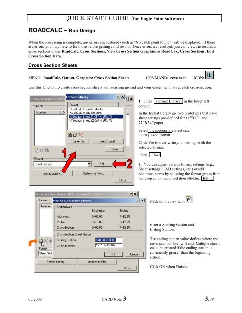
ROADCALC – Run Design QUICK START GUIDE (for Eagle Point software) When the processing is complete, any errors encountered (such as "No catch point found") will be displayed. If there are errors, you may have to fix those before getting valid results. Once errors are resolved, you can view the resultant cross sections under RoadCalc, Cross Sections, View Cross Section Graphics or RoadCalc, Cross Sections, Edit Cross Section Data. Cross Section Sheets MENU: RoadCalc, Output, Graphics: Cross Section Sheets COMMAND: rcxssheet ICON: Use this function to create cross section sheets with existing ground and your design template at each cross-section. 1. Click Format Library in the lower left corner. In the format library are two prototypes that have sheet settings pre-defined for 11”X17” and 22”X34” paper. Select the appropriate sheet size. Click Load format . Click Yes to over write your settings with the selected format. Click Close 2. You can adjust various format settings (e.g., Sheet settings, CAD settings, etc.) or add additional items by selecting the format group from the drop down menu and then clicking Edit… Click on the new icon Enter a Starting Station and Ending Station. The ending station value defines where the cross-section sheet will end. Multiple sheets could be created if the ending station is sufficiently greater than the beginning station. Click OK when Finished 05/2008 CADD Note 3 3.39
- Page 1 and 2: QUICK START GUIDE (for Eagle Point
- Page 3 and 4: QUICK START GUIDE (for Eagle Point
- Page 5 and 6: QUICK START GUIDE (for Eagle Point
- Page 7 and 8: PROCESS LIBRARY QUICK START GUIDE (
- Page 9 and 10: QUICK START GUIDE (for Eagle Point
- Page 11 and 12: QUICK START GUIDE (for Eagle Point
- Page 13 and 14: QUICK START GUIDE (for Eagle Point
- Page 15 and 16: DATA COLLECTION Edit formatted file
- Page 17 and 18: DATA TRANSFER QUICK START GUIDE (fo
- Page 19 and 20: COGO - Nodes Place Nodes QUICK STAR
- Page 21 and 22: COGO - Nodes QUICK START GUIDE (for
- Page 23 and 24: COGO Report QUICK START GUIDE (for
- Page 25 and 26: SURFACE MODELING Managing surface m
- Page 27 and 28: SURFACE MODELING Contours - preview
- Page 29 and 30: PROFILES QUICK START GUIDE (for Eag
- Page 31 and 32: ROADCALC QUICK START GUIDE (for Eag
- Page 33 and 34: ROADCALC Extract Cross-Sections QUI
- Page 35 and 36: ROADCALC Profiles QUICK START GUIDE
- Page 37: QUICK START GUIDE (for Eagle Point
- Page 41 and 42: ROADCALC Plan and Profile Sheets QU
- Page 43 and 44: ROADCALC QUICK START GUIDE (for Eag
- Page 45 and 46: SITE DESIGN Calculate Volumes QUICK
- Page 47 and 48: DRAFTING QUICK START GUIDE (for Eag
ROADCALC – Run Design<br />
<strong>QUICK</strong> <strong>START</strong> <strong>GUIDE</strong> (<strong>for</strong> <strong>Eagle</strong> <strong>Point</strong> <strong>software</strong>)<br />
When the processing is complete, any errors encountered (such as "No catch point found") will be displayed. If there<br />
are errors, you may have to fix those be<strong>for</strong>e getting valid results. Once errors are resolved, you can view the resultant<br />
cross sections under RoadCalc, Cross Sections, View Cross Section Graphics or RoadCalc, Cross Sections, Edit<br />
Cross Section Data.<br />
Cross Section Sheets<br />
MENU: RoadCalc, Output, Graphics: Cross Section Sheets COMMAND: rcxssheet ICON:<br />
Use this function to create cross section sheets with existing ground and your design template at each cross-section.<br />
1. Click Format Library in the lower left<br />
corner.<br />
In the <strong>for</strong>mat library are two prototypes that have<br />
sheet settings pre-defined <strong>for</strong> 11”X17” and<br />
22”X34” paper.<br />
Select the appropriate sheet size.<br />
Click Load <strong>for</strong>mat .<br />
Click Yes to over write your settings with the<br />
selected <strong>for</strong>mat.<br />
Click Close<br />
2. You can adjust various <strong>for</strong>mat settings (e.g.,<br />
Sheet settings, CAD settings, etc.) or add<br />
additional items by selecting the <strong>for</strong>mat group from<br />
the drop down menu and then clicking Edit…<br />
Click on the new icon<br />
Enter a Starting Station and<br />
Ending Station.<br />
The ending station value defines where the<br />
cross-section sheet will end. Multiple sheets<br />
could be created if the ending station is<br />
sufficiently greater than the beginning<br />
station.<br />
Click OK when Finished<br />
05/2008 CADD Note 3 3.39


