QUICK START GUIDE (for Eagle Point software)
QUICK START GUIDE (for Eagle Point software)
QUICK START GUIDE (for Eagle Point software)

Create successful ePaper yourself
Turn your PDF publications into a flip-book with our unique Google optimized e-Paper software.
<strong>QUICK</strong> <strong>START</strong> <strong>GUIDE</strong> (<strong>for</strong> <strong>Eagle</strong> <strong>Point</strong> <strong>software</strong>)<br />
CADD NOTE 3<br />
The purpose of this note is to provide a quick reference <strong>for</strong> doing basic procedures available with <strong>Eagle</strong> <strong>Point</strong> Software<br />
(2006-2007). It is not intended as a replacement <strong>for</strong> the manuals. There<strong>for</strong>e, not every topic is covered and the ones that<br />
are covered are not explained in complete detail. To view the manuals when <strong>Eagle</strong> <strong>Point</strong> is not running, select<br />
“Start, All Programs, <strong>Eagle</strong> <strong>Point</strong>, User Manuals”. To view manuals while running <strong>Eagle</strong> <strong>Point</strong>, select “Help, Online<br />
Documentation” from <strong>Eagle</strong> <strong>Point</strong>’s menu (see figure below). If you are viewing this document on a computer that has<br />
<strong>Eagle</strong> <strong>Point</strong> installed, use this link to view the <strong>Eagle</strong> <strong>Point</strong> Online User Manual . If help is needed <strong>for</strong> a topic, select<br />
“Help, Contents” from the <strong>Eagle</strong> <strong>Point</strong> menu and use the Contents, Index, or Find tabs as needed.<br />
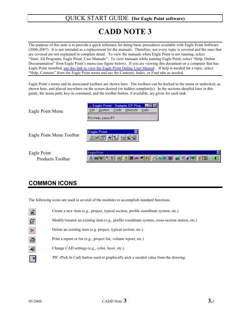
<strong>Eagle</strong> <strong>Point</strong>’s menu and its associated toolbars are shown here. The toolbars can be docked to the menu or undocked, as<br />
shown here, and placed anywhere on the screen desired (or hidden completely). In the sections detailed later in this<br />
guide, the menu path, key-in command, and the toolbar button, if available, are given <strong>for</strong> each task.<br />
<strong>Eagle</strong> <strong>Point</strong> Menu<br />
<strong>Eagle</strong> <strong>Point</strong> Menu Toolbar<br />
<strong>Eagle</strong> <strong>Point</strong><br />
Products Toolbar<br />
COMMON ICONS<br />
The following icons are used in several of the modules to accomplish standard functions.<br />
Create a new item (e.g., project, typical section, profile coordinate system, etc.)<br />
Modify/rename an existing item (e.g., profile coordinate system, cross-section station, etc.)<br />
Delete an existing item (e.g. project, typical section, etc.)<br />
Print a report or list (e.g., project list, volume report, etc.)<br />
Change CAD settings (e.g., color, layer, etc.)<br />
PIC (Pick In Cad) button used to graphically pick a needed value from the drawing.<br />
05/2008 CADD Note 3 3.1
FLOW CHARTS<br />
<strong>QUICK</strong> <strong>START</strong> <strong>GUIDE</strong> (<strong>for</strong> <strong>Eagle</strong> <strong>Point</strong> <strong>software</strong>)<br />
The following flow charts represent the general steps to take when working on a project. For more details related to a<br />
step, see the appropriate section later in this guide.<br />
Data Collection/Surface Modeling Profiles<br />
These steps will almost always be done since they<br />
provide a foundation <strong>for</strong> the remaining modules. The Profile module is used when you would like to<br />
draw a profile and annotate it. An example might<br />
be <strong>for</strong> a valley cross section.<br />
1. Start a new project<br />
(or open an existing one)<br />
2. Edit project settings<br />
(e.g., plot scales)<br />
3. Data Collection/Transfer<br />
a. download from collector<br />
- or -<br />
import from file<br />
b. edit file<br />
c. reduce<br />
4. Prepare data<br />
Edit/place nodes, breaklines, boundaries<br />
(can use COGO or Surface Modeling)<br />
5. Create surface model<br />
6. Preview or create & annotate contours<br />
(optional, but useful to view<br />
problems with surface model)<br />
7.<br />
Do contours show<br />
problems?<br />
No<br />
8. Proceed to appropriate module<br />
Profiles<br />
RoadCalc<br />
Yes<br />
Site Design<br />
1. Define a Profile Coordinate System<br />
(Tip: place this away from plan drawing<br />
so that the profile won’t be drawn on top<br />
of other objects)<br />
2. Construct the profile from<br />
a) Surface Model (assumes a surface<br />
model exists and<br />
a line to extract from<br />
is drawn),<br />
- or -<br />
b) Object (should be an object with<br />
elevations such as a 3D polyline)<br />
3. Construct a grid<br />
4. Annotate any desired features<br />
(e.g., point/grade breaks)<br />
5. Optional: Use PROFTABLE<br />
command to generate a table with<br />
station and elevation values <strong>for</strong> the<br />
profile.<br />
3.2 CADD Note 3 05/2008<br />
Done
<strong>QUICK</strong> <strong>START</strong> <strong>GUIDE</strong> (<strong>for</strong> <strong>Eagle</strong> <strong>Point</strong> <strong>software</strong>)<br />
RoadCalc<br />
The RoadCalc module is used when a project is based on a centerline alignment and you need to generate<br />
cross sections and compute volumes based on the average end area method. Examples would include dams,<br />
levees, terraces, etc.<br />
1. Create a sub-project.<br />
2. Create an alignment.<br />
3. Add a design surface.<br />
4. Extract cross-sections from<br />
original ground<br />
5. View/edit<br />
cross-sections<br />
6.<br />
Cross<br />
section<br />
problems?<br />
No<br />
7. Enter design profile<br />
Yes<br />
8. Construct typical section(s)<br />
9. If needed, add slopes to<br />
Slopes Library<br />
10. Add condition table(s)<br />
11. Enter design locations.<br />
6b.<br />
Fix surface<br />
model<br />
No<br />
6a.<br />
Manually<br />
Fix?<br />
Yes<br />
05/2008 CADD Not<br />
12. Run design.<br />
13. View/edit<br />
cross-sections<br />
14.<br />
Cross<br />
section<br />
problems?<br />
No<br />
15. View volumes<br />
Yes<br />
16. Draw catchlines and breaklines<br />
17. Drafting tasks as desired<br />
a) Annotate alignments/profiles<br />
b) Create cross section sheet(s)<br />
c) Create plan & profile sheet(s)<br />
Done<br />
14b.<br />
Fix profile,<br />
typical section,<br />
etc.<br />
No<br />
14a.<br />
Manually<br />
Fix?<br />
Yes<br />
e 3 3.3
<strong>QUICK</strong> <strong>START</strong> <strong>GUIDE</strong> (<strong>for</strong> <strong>Eagle</strong> <strong>Point</strong> <strong>software</strong>)<br />
Site Design<br />
The Site Design module is used <strong>for</strong> projecting slopes from feature lines and <strong>for</strong> computing volumes between<br />
2 surface models using a prismoidal method. Examples of projects that Site Design could be used <strong>for</strong> are<br />
lagoons, pits, building pads, etc.<br />
1. Draw feature lines with desired elevations.<br />
Yes<br />
3. Create a final surface model<br />
using feature lines. Use<br />
outer feature line as a boundary.<br />
DO NOT project slopes.<br />
4. Add a new surface model name<br />
to contain the balanced model.<br />
5. Balance volumes.<br />
Done<br />
2.<br />
Balance<br />
volumes?<br />
3.4 CADD Note 3 05/2008<br />
No<br />
3. Project slopes to<br />
original surface model.<br />
4. Create a final surface model<br />
using feature lines and<br />
projected lines. Use<br />
catchline as a boundary.<br />
5. Calculate volumes between<br />
original and final surface<br />
models..<br />
6.<br />
Volumes<br />
OK?<br />
Yes<br />
Done<br />
No 6a. Raise or lower<br />
feature lines<br />
as needed.
<strong>QUICK</strong> <strong>START</strong> <strong>GUIDE</strong> (<strong>for</strong> <strong>Eagle</strong> <strong>Point</strong> <strong>software</strong>)<br />
<strong>START</strong>ING A NEW PROJECT<br />
MENU: <strong>Eagle</strong> <strong>Point</strong>, File, New… COMMAND: newproj ICON:<br />
When you first start <strong>Eagle</strong> <strong>Point</strong>, you are in the<br />
project manager shown to the left.<br />
Click (bottom left icon) to create a new<br />
project.<br />
If you are working in a project and want to<br />
start a new one, select File, New from <strong>Eagle</strong><br />
<strong>Point</strong>’s menu.<br />
Select the type of item to create (e.g., <strong>Eagle</strong><br />
<strong>Point</strong> Project <strong>for</strong> a completely new project).<br />
Click Next ><br />
Enter the project description.<br />
Enter the project drawing name.<br />
See note below.<br />
Select the “Missouri Prototype Settings”<br />
prototype setting. This selection will be kept<br />
<strong>for</strong> all future projects until you select a<br />
different one.<br />
The prototype drawing field will be filled-in<br />
automatically.<br />
Click Finish .<br />
NOTE: Each project should be in its own folder (i.e., sub-directory).<br />
Examples: S:\Service_Center\NRCS\Engineering\Projects\WRP\SAMPLE1\SAMPLE1.dwg<br />
S:\Service_Center\NRCS\Engineering\Projects\01DAMS\OWNER1\OWNER2.dwg<br />
05/2008 CADD Note 3 3.5
<strong>QUICK</strong> <strong>START</strong> <strong>GUIDE</strong> (<strong>for</strong> <strong>Eagle</strong> <strong>Point</strong> <strong>software</strong>)<br />
OPENING AN EXISTING PROJECT<br />
MENU: <strong>Eagle</strong> <strong>Point</strong>, File, Open… COMMAND: openproj ICON:<br />
Highlight the desired project and click OK or click in the slide view to the right.<br />
NOTE: If this list becomes lengthy, you can limit the display by using filters. Click on and enter desired values <strong>for</strong><br />
description, drawing, and/or sub-project type. For example, enter a description of WRP* to list all projects beginning<br />
with WRP. The * is used as a wildcard. Make sure ”Filters” is checked.<br />
RENAMING AN EXISTING PROJECT<br />
MENU: <strong>Eagle</strong> <strong>Point</strong>, File, Rename… COMMAND: renameproj ICON:<br />
Highlight the desired project, enter a new description, and click OK .<br />
EDIT PROJECT SETTINGS<br />
Various settings can be changed as outlined below: Several of these have been set <strong>for</strong> you if the “Missouri Prototype<br />
Settings” was selected when creating the project.<br />
MENU: <strong>Eagle</strong> <strong>Point</strong>, System, Units COMMAND: projunit<br />
Edit angular, degree of curvature, linear, and area units.<br />
MENU: <strong>Eagle</strong> <strong>Point</strong>, System, Formats COMMAND: projfrmt<br />
Edit horizontal direction, node, and stationing <strong>for</strong>mats.<br />
MENU: <strong>Eagle</strong> <strong>Point</strong>, System, Precision COMMAND: projprec<br />
Edit angular, linear, area, volume, and station/offset precisions.<br />
MENU: <strong>Eagle</strong> <strong>Point</strong>, System, Default CAD Settings COMMAND: projcad ICON:<br />
Edit all the default settings <strong>for</strong> objects constructed in CAD.<br />
MENU: <strong>Eagle</strong> <strong>Point</strong>, Tools, Plot Scales COMMAND: plotscales<br />
Edit the horizontal and vertical scale settings.<br />
NOTE: <strong>Eagle</strong> <strong>Point</strong> uses the horizontal scale value in determining size of the text placed in the drawing (e.g., with<br />
a scale of 100 and a text size of .08, the text placed in the drawing will be 8’ tall).<br />
NOTE: Horizontal scale divided by vertical scale is used as a vertical stretch factor while creating profiles (e.g., a<br />
horizontal scale of 100 and vertical scale of 5 will result in profiles being exaggerated 20 times).<br />
3.6 CADD Note 3 05/2008
PROCESS LIBRARY<br />
<strong>QUICK</strong> <strong>START</strong> <strong>GUIDE</strong> (<strong>for</strong> <strong>Eagle</strong> <strong>Point</strong> <strong>software</strong>)<br />
The Process Library is a tool that helps guide a user through various steps needed to per<strong>for</strong>m tasks in a certain process.<br />
To start this tool, select<br />
Tools, Process Library… from the <strong>Eagle</strong> <strong>Point</strong> main menu.<br />
The instructions below assume you have started the tool and the Process Library window is open.<br />
Selecting library to use<br />
A library has been created <strong>for</strong> your use. Its name begins with NRCS_MO. If the NRCS_MO library is not the active<br />
one (shown in the title bar of the window), you will want to change to it.<br />
To select it, use the menu or icon method below to open the “Manage Process Libraries” window.<br />
MENU: File, Manage Process Libraries… ICON:<br />
Select the NRCS_MO library.<br />
Click OK .<br />
05/2008 CADD Note 3 3.7
PROCESS LIBRARY<br />
Using the process library<br />
<strong>QUICK</strong> <strong>START</strong> <strong>GUIDE</strong> (<strong>for</strong> <strong>Eagle</strong> <strong>Point</strong> <strong>software</strong>)<br />
The Process Library window is actually comprised of 2 windows: a "Processes" window (blue title bar) and a<br />
"Description" window (green title bar). You can collapse or expand either window by clicking on its title bar. A sample<br />
of this is shown below <strong>for</strong> the NRCS_MO process library.<br />
To use the library, simply follow the instructions below<br />
The "Processes" window contains a tree structure with a list<br />
of processes, tasks and steps.<br />
(flow chart icon) indicates a PROCESS.<br />
(checkmark icon) indicates a TASK.<br />
The following icons indicate a STEP<br />
<strong>Eagle</strong> <strong>Point</strong> command,<br />
CAD command,<br />
Other application,<br />
Hyperlink,<br />
None (just instructions)<br />
The "Description" window contains notes and detailed<br />
instructions <strong>for</strong> completing the process, task, or step.<br />
Highlight the desired process. Be sure to read any notes in the description area. If there is a + to the left of the process<br />
name, click on it to expand the tasks below it. You will normally step through the tasks and steps in a process from top<br />
to bottom.<br />
Highlight the desired task. Read and per<strong>for</strong>m any instructions given in the description area. If there is a + to the left<br />
of the task name, click on it to expand the steps and tasks below it.<br />
Highlight the desired step. If the step has a command associated with it (indicated by icon), you can double-click on it<br />
to invoke the command and then follow the instructions given in the description area.<br />
Simply do the tasks and steps in the order given <strong>for</strong> that process.<br />
When done, you can do File -> Exit or simply close the window.<br />
3.8 CADD Note 3 05/2008
<strong>QUICK</strong> <strong>START</strong> <strong>GUIDE</strong> (<strong>for</strong> <strong>Eagle</strong> <strong>Point</strong> <strong>software</strong>)<br />
NODE (Field Code) LIBRARY<br />
MENU: <strong>Eagle</strong> <strong>Point</strong>, System, Node (Field Code) Library COMMAND: nodelib ICON:<br />
A standard field code library “NRCS MO Field Codes” has been setup to utilize the national standard guidelines when<br />
topographic and design surveys are being per<strong>for</strong>med <strong>for</strong> data reduction and representation of engineering drawings.<br />
The “Node (Field Code) Library” screen shows the field code, description, attribute style, and a preview of the<br />
associated symbol <strong>for</strong> the current field code library.<br />
Attribute Styles<br />
If “NRCS MO Field Codes” is not the<br />
current field code library, select it from the<br />
drop-down list to make it the current one.<br />
If you wish to view or modify the attribute<br />
styles, click the “Attribute Styles…” button<br />
and refer to instructions below.<br />
If done viewing or modifying field codes,<br />
simply click “Close”<br />
The “Attribute Styles Library” window shows a<br />
list of Attribute Styles and a preview of how<br />
each style is placed in the drawing<br />
Three attribute styles were created <strong>for</strong> the<br />
NRCS MO Field Codes library. These are<br />
described below.<br />
MoTopo: <strong>Point</strong> Number, Description, and Elevation are plotted to the right of the node in this style. The field codes<br />
that utilize this style include such entries as Ground Shot, Topo, RT. Bank, Waterline, etc. These features<br />
are listed on the yellow sheet of the Field Code Cards.<br />
MoControl <strong>Point</strong>: <strong>Point</strong> Number, Description, and Elevation are plotted to the right of the node in this style and the<br />
Northing and Easting coordinates are plotted to the left of the node. The field codes that utilize this<br />
style include such entries as Control <strong>Point</strong>, Hub, TBM, etc. These features are listed on the blue<br />
sheet of the Field Code Cards.<br />
MoFeatures: <strong>Point</strong> Number, Description, and Elevation are plotted to the right of the node in this style. The field<br />
codes that utilize this style include such entries as Building, Power Poles, Buried Utilities, etc. These<br />
features are listed on the green sheet of the Field Code Cards.<br />
05/2008 CADD Note 3 3.9
<strong>QUICK</strong> <strong>START</strong> <strong>GUIDE</strong> (<strong>for</strong> <strong>Eagle</strong> <strong>Point</strong> <strong>software</strong>)<br />
NODE (Field Code) LIBRARY – Attribute Styles<br />
By establishing the three different attribute styles and utilizing the<br />
layers created by using the established field codes, the user<br />
should be able to freeze and thaw selected layers to ease the<br />
drawing of various line features (e.g., profiles, breaklines,<br />
boundaries, etc.). Below is an example of this.<br />
This is a typical plot of survey points. It can lay over the top of<br />
each other, be very cluttered and difficult to “connect the dots” if<br />
trying to draw any linework.<br />
The V.FCOD.CLIN layer represents the<br />
centerline symbol. So, <strong>for</strong> this example, if<br />
you were to freeze all the V.FCOD.* layers<br />
but V.FCOD.CLIN, only the “centerline”<br />
nodes would be displayed.<br />
The drawing would become less cluttered and it would be much<br />
easier to draw your centerline from node to node as shown in this<br />
figure.<br />
3.10 CADD Note 3 05/2008
<strong>QUICK</strong> <strong>START</strong> <strong>GUIDE</strong> (<strong>for</strong> <strong>Eagle</strong> <strong>Point</strong> <strong>software</strong>)<br />
NODE (Field Code) LIBRARY<br />
Numeric Code Symbols Chart<br />
The figure below shows the symbols used <strong>for</strong> each numeric field code along with its default description.<br />
05/2008 CADD Note 3 3.11
<strong>QUICK</strong> <strong>START</strong> <strong>GUIDE</strong> (<strong>for</strong> <strong>Eagle</strong> <strong>Point</strong> <strong>software</strong>)<br />
NODE (Field Code) LIBRARY<br />
Alphanumeric Code Symbols Chart<br />
The figure below shows the symbols used <strong>for</strong> each alphanumeric field code along with its default description.<br />
3.12 CADD Note 3 05/2008
<strong>QUICK</strong> <strong>START</strong> <strong>GUIDE</strong> (<strong>for</strong> <strong>Eagle</strong> <strong>Point</strong> <strong>software</strong>)<br />
CONFIGURE PRINTER (<strong>for</strong> <strong>Eagle</strong> <strong>Point</strong> Reports)<br />
MENU: <strong>Eagle</strong> <strong>Point</strong>, File, Print Setup COMMAND: prntsets<br />
You can choose to send <strong>Eagle</strong> <strong>Point</strong> reports to your default printer or to a file. To set the default printer, select Start<br />
(Windows start button), Printers and Faxes; right click on the desired printer and then select Set as Default.<br />
TOOLS<br />
LAYER COMMANDS<br />
MENU: <strong>Eagle</strong>, Products, Tools, Layer Commands<br />
Select Printer.<br />
Set other settings (i.e., headers, lines/page,<br />
margin, font, etc.) as desired.<br />
Click OK<br />
This menu includes utilities that allow you to set the current layer to that of a selected entity, to find out (list) what layer<br />
a node or entity is on, and freeze the layer of a selected entity.<br />
PLOT SCALES<br />
MENU: <strong>Eagle</strong> <strong>Point</strong>, Tools, Plot Scales COMMAND: plotscales<br />
Enter desired horizontal and vertical plot scales.<br />
The horizontal scale affects size of text placed by <strong>Eagle</strong> <strong>Point</strong>.<br />
The ratio of horizontal over vertical scales is the “vertical stretch<br />
factor” used in creating profiles.<br />
Since the size of any text placed by <strong>Eagle</strong> <strong>Point</strong> (e.g., node attribute text) is determined by these plot scale settings, it is<br />
important to have these set as desired be<strong>for</strong>e reducing any nodes.<br />
05/2008 CADD Note 3 3.13
DATA COLLECTION<br />
<strong>QUICK</strong> <strong>START</strong> <strong>GUIDE</strong> (<strong>for</strong> <strong>Eagle</strong> <strong>Point</strong> <strong>software</strong>)<br />
MENU: <strong>Eagle</strong> <strong>Point</strong>, Products, Data Collection COMMAND: epdc ICON:<br />
This will load the data collection menu and toolbar. The tasks listed below assume you are working from this menu and<br />
toolbar.<br />
Prepare data collector:<br />
Connect data collector (e.g., SDR33) to a serial port.<br />
Check that data collector settings are correct:<br />
SDR33 Settings (FUNC, Communications, COM)<br />
Port: Top<br />
Modem: No<br />
Baud Rate: 9600<br />
Word Length: 8<br />
Parity: Not set<br />
Stop bit: 1<br />
Output delay: 0<br />
File: No<br />
Downloading<br />
MENU: Data Collection, Jobs, Download from Collector COMMAND: download ICON:<br />
Job name: Enter a descriptive name of data to be downloaded.<br />
Format: Select collector you are using.<br />
Serial Port: Select the computer’s serial port you are using.<br />
Baud Rate: Select rate to match that of collector.<br />
Data Bits: Select to match that of collector.<br />
(With Trimble TSC data collectors, you may need to set the data bits to<br />
“7, Odd” even though the collector settings are “8, None”)<br />
Click OK .<br />
This screen appears instructing you to prepare data collector.<br />
On data collector, select job to download in "Communications<br />
Send (or Output).<br />
Press key on computer and then key on collector (30 sec.<br />
window). Data should begin scrolling across screen. If<br />
not, check that communication settings on collector and<br />
computer match.<br />
Once download is complete, press a key on the computer. If<br />
the download window is not active, click in it to make it<br />
active and then press a key. You should then be returned<br />
to the Data Collection dialog box. Remember to shut off<br />
data collector if finished.<br />
3.14 CADD Note 3 05/2008
DATA COLLECTION<br />
Edit <strong>for</strong>matted file<br />
<strong>QUICK</strong> <strong>START</strong> <strong>GUIDE</strong> (<strong>for</strong> <strong>Eagle</strong> <strong>Point</strong> <strong>software</strong>)<br />
MENU: Data Collection, Jobs, Edit Formatted File COMMAND: edit<strong>for</strong>mat ICON:<br />
Select the desired job name to edit. The field book editor should then load. The editor operates similar to a spreadsheet<br />
editor. You simply move the cursor to the desired cell or field and make your changes. A record or row is comprised of<br />
a tag and its corresponding value. Some examples of tags are as follows:<br />
PN: <strong>Point</strong> number<br />
SH: Staff (rod) height<br />
XC: X (Easting) coordinate<br />
YC: Y (Northing) coordinate<br />
ZC: Z (elevation) coordinate<br />
PD: <strong>Point</strong> description (code)<br />
To determine what any other tag code means, position the cursor on the tag or the data field of that tag. The status line<br />
(bottom of your screen) will display the description of that tag.<br />
To activate top menu bar, hold down "Alt" or use mouse/digitizer to click on desired option.<br />
To change text throughout the whole file (e.g., change CL_LEVEE to 70.1 CL_LEVEE), select Edit and then Global<br />
edit (or click icon). Enter desired in<strong>for</strong>mation.<br />
To delete a line (i.e., a row), highlight desired row and select Tools, Delete Row or click icon.<br />
To insert a row, highlight row to insert new row above and select Tools, Insert Row or click icon.<br />
To search <strong>for</strong> a string, select Edit, Find , press Ctrl-F, or click icon and then enter text or tag desired.<br />
A common error that occurs in a survey is an incorrect rod height. How to correct it depends on what type of data was<br />
downloaded, either POS (position: northing, easting, elevation) or OBS (raw data: angles, slope distance).<br />
For POS data, the elevation field (ZC or ZZ) will need to be changed <strong>for</strong> each point affected by the rod height error.<br />
This can be done individually <strong>for</strong> each point or <strong>for</strong> all of them by using Global edit and adding a positive value (raising)<br />
or a negative value (lowering) to the elevation field. See example below.<br />
Choose method <strong>for</strong> selecting nodes.<br />
Single, Range, Description, or All<br />
Enter values based on method chosen.<br />
(e.g., beginning and ending node ids <strong>for</strong> range)<br />
Select field to change.<br />
Select action: Add, Multiply, or Set<br />
Enter appropriate value.<br />
Click Apply.<br />
For OBS data, you can simply correct the rod<br />
(i.e., staff) height record. When the data is reduced, the elevations computed will then be correct.<br />
When finished editing, select File, Exit and answer Yes to save.<br />
05/2008 CADD Note 3 3.15
DATA COLLECTION<br />
Import ASCII file<br />
<strong>QUICK</strong> <strong>START</strong> <strong>GUIDE</strong> (<strong>for</strong> <strong>Eagle</strong> <strong>Point</strong> <strong>software</strong>)<br />
MENU: Data Collection, Jobs, Import ASCII File COMMAND: dcimp ICON:<br />
Reduction settings<br />
Enter a job name <strong>for</strong> the imported points.<br />
Enter the file name or click the folder icon to browse to<br />
the folder. This file will normally be a “csv” file (i.e.,<br />
comma delimited text file) that comes from another<br />
program (e.g., Excel, Trimble Geomatics, etc.).<br />
Select “Coordinate” <strong>for</strong>mat. This <strong>for</strong>mat is<br />
<strong>Point</strong>#, Northing, Easting, Elevation, Description<br />
so the file being imported should match that <strong>for</strong>mat.<br />
MENU: Data Collection, Options, Reduction Settings COMMAND: dcset ICON:<br />
Change various settings (e.g., collector, default field code, shot averaging, etc.) prior to reducing survey data. To set the<br />
default field code, click the “Graphics” tab and select the desired code.<br />
Reduce<br />
MENU: Data Collection, Jobs, Reduce COMMAND: reduce ICON:<br />
This processes a data file into the drawing (i.e., places nodes with point symbols and line work).<br />
Check data in plan view and, if so desired, in elevation view (AutoCAD command: -view, Orthographic, Front).<br />
If there are errors and you would like to edit the raw data file and re-reduce the data, return to “Edit <strong>for</strong>matted file” steps<br />
above.<br />
3.16 CADD Note 3 05/2008
DATA TRANSFER<br />
<strong>QUICK</strong> <strong>START</strong> <strong>GUIDE</strong> (<strong>for</strong> <strong>Eagle</strong> <strong>Point</strong> <strong>software</strong>)<br />
MENU: <strong>Eagle</strong> <strong>Point</strong>, Products, Data Transfer COMMAND: epdt ICON:<br />
This will load the data transfer menu and toolbar. The tasks listed below assume you are working from this menu and<br />
toolbar.<br />
Import File<br />
MENU: Data Transfer, Transfer, Import File COMMAND: dtimp ICON:<br />
You can import an ASCII file using one of a variety of <strong>for</strong>mats. The ASCII file can be one created by another <strong>software</strong><br />
program and you wish to import the points into <strong>Eagle</strong> <strong>Point</strong>.<br />
NOTE: Importing a file here will not do any field code or line work processing. If your descriptions contain field<br />
coding that you want processed, use the Data Collection routine.<br />
The nodes will then be placed in the drawing.<br />
Report - Nodes<br />
Enter or select the desired file.<br />
Select desired <strong>for</strong>mat (if not available, you may need to<br />
“Edit User Formats” and create the needed <strong>for</strong>mat).<br />
Click Settings to<br />
Specify point type (usually node), default field<br />
code, node number to add, starting node ID, and<br />
range of points and/or elevations.<br />
Click Duplicates to list duplicate nodes between file<br />
and drawing.<br />
Click Edit File to make changes to the data file.<br />
Click OK .<br />
MENU: Report, Nodes COMMAND: dtnode ICON:<br />
This routine allows you to list selected nodes (see selecting nodes under COGO section). After selecting the nodes, the<br />
list will be displayed. To print the list, click and select items to print. This same routine can be run under<br />
<strong>Eagle</strong> <strong>Point</strong>, Products, COGO, Report, Nodes.<br />
05/2008 CADD Note 3 3.17
<strong>QUICK</strong> <strong>START</strong> <strong>GUIDE</strong> (<strong>for</strong> <strong>Eagle</strong> <strong>Point</strong> <strong>software</strong>)<br />
COGO (coordinate geometry)<br />
MENU: <strong>Eagle</strong> <strong>Point</strong>, Products, COGO COMMAND: epcg ICON:<br />
This will load the COGO menu and toolbar. The tasks listed below assume you are working from this menu and toolbar.<br />
Nodes<br />
Under the Nodes menu, you can do various functions related to nodes, such as place, move, copy, erase, renumber, and<br />
raise/lower nodes to name a few. Several of these functions need you to select the nodes desired.<br />
Selecting Nodes<br />
Nodes can be selected in a variety of ways. To add nodes to the selection list, choose “Select” mode. To remove them,<br />
choose “Unselect” mode. Choose “Selection Method” as explained below.<br />
Single: Enter a single node number (e.g., 1000)<br />
Elevation Range: Enter a range of elevations (e.g., 100-110)<br />
Range: Enter a range of node numbers (e.g., 1000-1100)<br />
All: All nodes are selected<br />
AutoCAD: Select nodes using normal AutoCAD selection<br />
methods (window, crossing, fence, etc.)<br />
Proximity: Select a base point, and enter radial distance. This<br />
will select nodes within the entered distance from the base point.<br />
Description: Enter a description (* is used as a wildcard).<br />
Examples: TREE finds nodes with description of Tree<br />
TREE* finds nodes with descriptions beginning with<br />
Tree (e.g., Trees or Treehouse)<br />
Block: Enter the block name of the symbol placed with the<br />
node.<br />
Field Code: Select the field code used to place the node (e.g.,<br />
32 DOT).<br />
Several of the selection methods require you to enter desired in<strong>for</strong>mation. Much of this in<strong>for</strong>mation can be obtained by<br />
clicking the PIC button and selecting the item graphically. After entering this in<strong>for</strong>mation, click Apply to select the<br />
nodes. If desired, you can choose another selection method and select more nodes. When done selecting nodes, click<br />
Next > to continue with current command. If there is no Next > button, then click Close .<br />
3.18 CADD Note 3 05/2008
COGO - Nodes<br />
Place Nodes<br />
<strong>QUICK</strong> <strong>START</strong> <strong>GUIDE</strong> (<strong>for</strong> <strong>Eagle</strong> <strong>Point</strong> <strong>software</strong>)<br />
MENU: COGO, Nodes, Place Nodes COMMAND: placenode ICON:<br />
You can place a node at a graphically selected location in your drawing. Some of the prompts shown below may not<br />
appear depending on the node placement options set (COGO, Settings, Entry Options).<br />
If the “Place Nodes, Enter Settings” window appears, click Next > to skip past it<br />
Click Apply to place the node or Close when done.<br />
Enter the Node ID.<br />
Enter the northing, easting and elevation coordinates.<br />
(or you can click and pick a point graphically.)<br />
Select a field code.<br />
(Note: Codes 200, 201, PN, and PNX have been added to the<br />
NRCS Field Code library <strong>for</strong> your use here. 200 and PNX are<br />
<strong>for</strong> nodes that will be excluded from the surface model; 201 and<br />
PN nodes will be included in a surface model).<br />
Enter a description <strong>for</strong> the node.<br />
Modify Nodes<br />
MENU: COGO, Nodes, Modify COMMAND: modifynode<br />
This allows changing just about any aspect of the node and its attributes (e.g., Change color, layer and text style of<br />
description attribute). Select the desired nodes as described above under “Selecting Nodes”.<br />
Highlight desired item in left window.<br />
(e.g., Description)<br />
Check the desired properties to change<br />
(e.g., Value, Layer, etc.)<br />
Enter or select appropriate value(s).<br />
Click Apply .<br />
05/2008 CADD Note 3 3.19
COGO - Nodes<br />
<strong>QUICK</strong> <strong>START</strong> <strong>GUIDE</strong> (<strong>for</strong> <strong>Eagle</strong> <strong>Point</strong> <strong>software</strong>)<br />
Match Nodes<br />
MENU: COGO, Nodes, Match COMMAND: matchnode<br />
This allows changing the field code <strong>for</strong> nodes (e.g., Change node symbol from • to +).<br />
If the “Match Nodes, Enter Settings” window appears, click Next > to skip past it. Select the desired nodes as described<br />
above under “Selecting Nodes”.<br />
Either click and select a node to match, or<br />
select the desired field code to use<br />
Choose to hold existing description or not (use description of<br />
new field code).<br />
Click Apply .<br />
Click Close .<br />
Swivel Nodes<br />
MENU: COGO, Nodes, Swivel COMMAND: swivelnode<br />
A single or group of nodes and their attributes (point #, description, elevation) can be rotated around the node.<br />
If the “Swivel Nodes, Enter Settings” window appears, click Next > to skip past it. Select the desired nodes as<br />
described above under “Selecting Nodes”.<br />
Choose absolute or relative rotation.<br />
Enter corresponding angle (and direction <strong>for</strong> relative).<br />
Click Next > .<br />
Selected nodes will be listed.<br />
Click Apply , then Close .<br />
Renumber/Rename Nodes<br />
MENU: COGO, Nodes, Renumber/Rename COMMAND: renumnode<br />
This command will allow you to add or subtract a value from the point numbers of selected nodes.<br />
If the “Renumber/Rename Nodes, Enter Settings” window appears, click Next > to skip past it. Select the desired nodes<br />
as described above under “Selecting Nodes”. Enter the desired number to add (positive) or subtract (negative). Click<br />
Next > . The selected nodes will be listed. Click Apply .<br />
3.20 CADD Note 3 05/2008
COGO - Nodes<br />
<strong>QUICK</strong> <strong>START</strong> <strong>GUIDE</strong> (<strong>for</strong> <strong>Eagle</strong> <strong>Point</strong> <strong>software</strong>)<br />
Raise/Lower Nodes<br />
MENU: COGO, Nodes, Raise/Lower COMMAND: raisenode<br />
This command will allow you to change the elevations of nodes.<br />
If the “Raise/Lower Nodes, Enter Settings” window appears, click Next > to skip past it. Select the desired nodes as<br />
described above under “Selecting Nodes”. Enter the absolute or relative elevation change desired. Click Next > . The<br />
selected nodes will be listed. Click Apply .<br />
Edit Nodes<br />
MENU: COGO, Nodes, Edit COMMAND: editnode ICON:<br />
This command allows you to edit a node.<br />
If the “Edit Node, Enter Settings” window appears, click Next > to skip past it.<br />
Enter or select the desired node.<br />
Change desired attributes.<br />
Click Apply .<br />
Click Close when done.<br />
05/2008 CADD Note 3 3.21
COGO<br />
Report<br />
Nodes<br />
<strong>QUICK</strong> <strong>START</strong> <strong>GUIDE</strong> (<strong>for</strong> <strong>Eagle</strong> <strong>Point</strong> <strong>software</strong>)<br />
MENU: COGO, Report, Nodes COMMAND: cgnode ICON:<br />
This routine allows you to list in<strong>for</strong>mation on selected nodes. Select the desired nodes as described above under<br />
“Selecting Nodes”. Click Close to remove the selection window. The nodes are listed in another window as shown<br />
below.<br />
You can change a column width (or hide it completely) by dragging the line to the right of a column header left or right.<br />
You can click Clear to erase the entire list, “Select Nodes” to re-select nodes, or Close to exit.<br />
You can also click to print the list.<br />
Select the columns to print by clicking on the box<br />
under the Print column.<br />
Once you get an arrangement you like, you can click<br />
“Save Settings as Default” to save this as the default <strong>for</strong><br />
later prints.<br />
Click Print .<br />
3.22 CADD Note 3 05/2008
COGO<br />
Report<br />
<strong>QUICK</strong> <strong>START</strong> <strong>GUIDE</strong> (<strong>for</strong> <strong>Eagle</strong> <strong>Point</strong> <strong>software</strong>)<br />
Unused Nodes<br />
MENU: COGO, Report, Unused Nodes COMMAND: cgunused<br />
This routine allows you to list unused node numbers.<br />
Resolve Duplicate Nodes<br />
The report to the left shows that node numbers 5 through 49, 51<br />
through 999 and those greater than 1001 are not being used.<br />
MENU: COGO, Report, Resolve Duplicate Nodes COMMAND: cgdupnode ICON:<br />
This routine will assist in fixing duplicate node numbers.<br />
All duplicate node numbers are listed.<br />
Click to print the list.<br />
Select the method to use to handle the duplicate nodes:<br />
You can keep the highlighted node(s), renumber it,<br />
delete it(them), or average the highlighted nodes.<br />
Click Apply after selecting nodes and method.<br />
Click Close when done.<br />
05/2008 CADD Note 3 3.23
SURFACE MODELING<br />
<strong>QUICK</strong> <strong>START</strong> <strong>GUIDE</strong> (<strong>for</strong> <strong>Eagle</strong> <strong>Point</strong> <strong>software</strong>)<br />
MENU: <strong>Eagle</strong> <strong>Point</strong>, Products, Surface Modeling COMMAND: epsm ICON:<br />
This will load the surface modeling menu and toolbar. The tasks listed below assume you are working from this menu<br />
and toolbar.<br />
Notes on breaklines<br />
NOTE: Any line meeting the following criteria is considered a break line by the program. A break line is a line<br />
between two points that indicates a straight grade exists between those two points. The program will not allow a triangle<br />
side to cross this line.<br />
1) The line is on a thawed unmasked layer that does not have a layer name ending in $X.<br />
2) Each endpoint of the line must either<br />
a) have a node at or above the elevation of the endpoint, or<br />
b) have the correct elevation associated with it.<br />
3) The endpoint elevations or node elevations at or above the endpoints must fall within range specified in<br />
surface model definition.<br />
To not use a line as a break line, you can put it on a frozen layer, a layer ending in $X, a masked layer, or you can mask<br />
the line as excluded (Surface Modeling, Construct, Mask Objects).<br />
3.24 CADD Note 3 05/2008
SURFACE MODELING<br />
Managing surface models<br />
<strong>QUICK</strong> <strong>START</strong> <strong>GUIDE</strong> (<strong>for</strong> <strong>Eagle</strong> <strong>Point</strong> <strong>software</strong>)<br />
MENU: Surface Modeling, Prepare, Manage Surface Models COMMAND: smman ICON:<br />
Adding a new model<br />
Click:<br />
bottom left icon to add a new surface model (see below).<br />
to modify highlighted surface model.<br />
to copy a surface model.<br />
to delete the highlighted sureface model.<br />
to view properties of surface model.<br />
ICON:<br />
To load prototype settings from a library,<br />
click on the icon and see below <strong>for</strong> further<br />
instructions.<br />
Enter a description <strong>for</strong> the surface model.<br />
Change minimum and maximum elevations, if<br />
needed.<br />
Under the “Contours” tab, enter desired values<br />
<strong>for</strong> contour intervals, factors, etc.<br />
NOTE: If you enter a description and then load<br />
prototype settings from the library, you will need<br />
to re-enter your description because it will be<br />
overwritten.<br />
Select a prototype and click “Load Prototype”.<br />
A standard one called NRCS_MO Existing Ground has been provided.<br />
Answer Yes to the prompt you get about over writing your current settings.<br />
05/2008 CADD Note 3 3.25
SURFACE MODELING<br />
Making a surface model<br />
<strong>QUICK</strong> <strong>START</strong> <strong>GUIDE</strong> (<strong>for</strong> <strong>Eagle</strong> <strong>Point</strong> <strong>software</strong>)<br />
MENU: Surface Modeling, Triangulate, Surface Model COMMAND: maketin ICON:<br />
Select surface model.<br />
If using a boundary, select appropriate type.<br />
If using void regions, select appropriate type.<br />
Select desired options<br />
Click Apply to build the surface model.<br />
Select the objects you want to use in making the surface model.<br />
If a boundary or void regions were chosen, select those objects. The boundary and void regions must be closed<br />
polylines.<br />
Click Close .<br />
Once a Surface Model is made, it can be used <strong>for</strong> the following applications:<br />
Surface Modeling<br />
Contours and grids<br />
RoadCalc<br />
Cross-sections from surface model<br />
Site Design<br />
Slope projections, depth contours, volumes, etc.<br />
Profiles<br />
Extract profiles from object or surface model<br />
Checking surface model with tracking<br />
MENU: Surface Modeling, Triangulate, Track Coordinates COMMAND: smtrack ICON:<br />
Select surface model to track.<br />
Click Apply .<br />
Move cursor around area where surface model should be.<br />
If no elevation is shown, there is a problem with the surface model.<br />
If elevations are shown, make sure they are correct.<br />
3.26 CADD Note 3 05/2008
SURFACE MODELING<br />
Contours – preview and make<br />
<strong>QUICK</strong> <strong>START</strong> <strong>GUIDE</strong> (<strong>for</strong> <strong>Eagle</strong> <strong>Point</strong> <strong>software</strong>)<br />
MENU: Surface Modeling, Contours, Preview COMMAND: prevcont ICON:<br />
Use preview to display the contours be<strong>for</strong>e actually placing them in the drawing. This will allow you to determine any<br />
problems with the surface model. The problem can then be corrected (via breaklines, editting nodes, etc.) and the<br />
surface model recreated. Once the preview is acceptable, create the desired contours using the actions below.<br />
MENU: Surface Modeling, Contours, Make Intermediate & Index COMMAND: makecont ICON:<br />
MENU: Surface Modeling, Contours, Make Index COMMAND: makeindex<br />
MENU: Surface Modeling, Contours, Make Intermediate COMMAND: makeint<br />
MENU: Surface Modeling, Contours, Make User-Defined COMMAND: makeuser ICON:<br />
Select the Surface Model.<br />
Select desired options.<br />
Click Apply .<br />
Make User Defined Contours allows you to have a user specified contour line created (e.g., at a pool elevation of<br />
92.3).<br />
Contours – annotate<br />
MENU: Surface Modeling, Contours, Annotate COMMAND: anncont ICON:<br />
Select desired surface model.<br />
Choose which contours to annotate.<br />
Select which method to use:<br />
Crossing: you draw a line across contours where<br />
you wish to place the labels.<br />
Interval: places labels at the specified interval.<br />
Endpoints: places labels at the ends of contours.<br />
Change settings: placement, symbol, breaks, direction.<br />
Choose “Erase…” if you want to erase old contours.<br />
CAD Settings: layer, color, text style and height.<br />
Click Apply .<br />
If the crossing method is used, you need to pick the start and end points <strong>for</strong> a line that intersects the contour where you<br />
want the contour label.<br />
05/2008 CADD Note 3 3.27
PROFILES<br />
<strong>QUICK</strong> <strong>START</strong> <strong>GUIDE</strong> (<strong>for</strong> <strong>Eagle</strong> <strong>Point</strong> <strong>software</strong>)<br />
MENU: <strong>Eagle</strong> <strong>Point</strong>, Products, Profiles COMMAND: eppr ICON:<br />
This will load the profiles menu and toolbar. The tasks listed below assume you are working from this menu and<br />
toolbar.<br />
Setup – Profile Coordinate Systems<br />
This routine manages (activates, adds, modifies, deletes) Profile Coordinate Systems (PCS's). You can add Profile<br />
Coordinate Systems (PCS's) to either your plan drawing or profile drawing. You should make sure the horizontal and<br />
vertical scales are set correctly (<strong>Eagle</strong> <strong>Point</strong>, Tools, Plot Scales) be<strong>for</strong>e adding a PCS. Changing the scales after adding<br />
a PCS results in the coordinates being incorrect.<br />
MENU: Profiles, Setup, Profile Coordinate Systems COMMAND: prpcs ICON:<br />
Select the desired PCS and click Close to make it active.<br />
or<br />
Click to create a new PCS. See dialog window below.<br />
Click Close .<br />
Enter a name <strong>for</strong> the PCS.<br />
You can either key in X and Y values or click (PIC button)<br />
and select a point graphically in the drawing.<br />
This point should be in a blank area of your drawing.<br />
Enter the station and elevation corresponding to the X and Y<br />
values.<br />
Select desired orientation (usually will be left to right).<br />
Click OK and then Close from the setup window.<br />
3.28 CADD Note 3 05/2008
PROFILES<br />
<strong>QUICK</strong> <strong>START</strong> <strong>GUIDE</strong> (<strong>for</strong> <strong>Eagle</strong> <strong>Point</strong> <strong>software</strong>)<br />
Construct - Profile From Surface Model<br />
This option will extract elevation data from a surface model (i.e., must have previously used Surface Modeling, Make<br />
Surface model to have created a surface model).<br />
MENU: Profiles, Construct, Profile from Surface Model COMMAND: prfromsm ICON:<br />
Select type of object selection (usually complex object)<br />
Choose either Preview or Place in CAD<br />
Select the surface model(s) to use.<br />
Click OK .<br />
Select the object (i.e., line, polyline, etc.) to profile.<br />
If RoadCalc PCS is the active PCS,<br />
the RoadCalc centerline alignment will be used to base stationing on;<br />
otherwise,<br />
you will be prompted <strong>for</strong> the object to base stationing on. This will usually be the same entity that is being profiled.<br />
However, it can be different. For example, if you are profiling the channel upstream and want to base the<br />
stationing on the centerline of the dam, you can select the centerline alignment <strong>for</strong> stationing.<br />
If the selected object to base stationing on is not an alignment,<br />
you are asked to click near the beginning of the alignment and enter the starting station (BOP).<br />
The profile should be created and placed according to the current PCS. You may need to zoom or pan to see the profile.<br />
Construct - Profile From Object<br />
This option will extract the elevations directly from an entity in the drawing. This requires the entity to be 3-D (e.g., 3D<br />
polyline [3DPOLY] instead of a 2D polyline [PLINE] ).<br />
MENU: Profiles, Construct, Profile from Object COMMAND: prfromobj ICON:<br />
Select the entity (i.e., 3D polyline) to profile.<br />
If RoadCalc PCS is the active PCS,<br />
the RoadCalc centerline alignment will be used to base stationing on,<br />
otherwise<br />
you will be prompted <strong>for</strong> the object to base stationing on. This will usually be the same entity that is being profiled.<br />
However, it can be different. For example, if you are profiling the channel upstream and want to base the<br />
stationing on the centerline of the dam, you can select the centerline alignment <strong>for</strong> stationing.<br />
If the selected object to base stationing on is not an alignment,<br />
you are asked to click near the beginning of the alignment and enter the starting station (BOP).<br />
The profile should be created and placed according to the current PCS. You may need to zoom or pan to see the profile.<br />
05/2008 CADD Note 3 3.29
PROFILES<br />
Construct Grid<br />
<strong>QUICK</strong> <strong>START</strong> <strong>GUIDE</strong> (<strong>for</strong> <strong>Eagle</strong> <strong>Point</strong> <strong>software</strong>)<br />
MENU: Profiles, Construct, Grid COMMAND: prgrid ICON:<br />
This option allows you to place a grid with stations and elevations onto a profile.<br />
Enter the desired grid setting values.<br />
After entering desired values, click OK and select the lower left point of the grid. The point selected will be a multiple<br />
of the station interval and the elevation interval.<br />
NOTE: The default settings in Missouri’s prototype have the fine grid lines turned off. You should use the<br />
DOTGRID tool (see CADD Note 8) to add fine grids.<br />
3.30 CADD Note 3 05/2008
ROADCALC<br />
<strong>QUICK</strong> <strong>START</strong> <strong>GUIDE</strong> (<strong>for</strong> <strong>Eagle</strong> <strong>Point</strong> <strong>software</strong>)<br />
RoadCalc uses sub-projects. A sub-project could be considered as a project or structure related to a particular centerline.<br />
For example, you would create one sub-project <strong>for</strong> the dam and one <strong>for</strong> the auxiliary spillway. There is no longer a<br />
“Sub-project Manager”. Sub-projects are now managed via the project manager window. You will need to create or<br />
open a RoadCalc sub-project be<strong>for</strong>e using RoadCalc functions. This is similar to the “starting a new project” and<br />
“opening an existing project” sections above.<br />
To create a new sub-project, click on (bottom left icon of <strong>Eagle</strong> <strong>Point</strong> project manager window).<br />
Select RoadCalc sub-project.<br />
The current project should be highlighted.<br />
If this is incorrect, highlight the correct one.<br />
Enter a sub-project number.<br />
Enter a description<br />
Select a prototype.<br />
NRCS_MO Embankment contains settings <strong>for</strong><br />
straight alignments with multiple PIs.<br />
NRCS_MO Aux.Spwy contains settings <strong>for</strong> curved<br />
alignments with PC, PI, and PT data.<br />
Click Next> .<br />
In the next window that appears, you will usually<br />
use the defaults (i.e., use the current project<br />
drawing).<br />
Click Finish .<br />
MENU: <strong>Eagle</strong> <strong>Point</strong>, Products, RoadCalc COMMAND: eprc ICON:<br />
This will load the RoadCalc menu and toolbar. The RoadCalc tasks listed below assume you are working from this<br />
menu and toolbar.<br />
05/2008 CADD Note 3 3.31
ROADCALC<br />
Alignments<br />
<strong>QUICK</strong> <strong>START</strong> <strong>GUIDE</strong> (<strong>for</strong> <strong>Eagle</strong> <strong>Point</strong> <strong>software</strong>)<br />
This is where you enter/edit horizontal alignments (centerlines). An alignment can be entered directly, drawn using<br />
AutoCAD functions (line, polyline, or arcs), or with COGO, Survey, Alignment. If drawn in AutoCAD, the objects<br />
need to be converted to an alignment.<br />
MENU: RoadCalc, Alignment, Convert Objects to Alignment COMMAND: rcalign ICON:<br />
Click on the entity (or entities) which make up the centerline alignment. Press ENTER when done selecting.<br />
Click a point near the beginning of the alignment.<br />
Change the Beginning Station to the desired BOP station.<br />
Click on Apply .<br />
The centerline should change layer, color, and linetype to the ones specified in the Alignment Settings box. This should<br />
be C.Clin.New_ or C.Clin.Auxs.New_ layer, red color, and Center linetype. This indicates that the data <strong>for</strong> the<br />
centerline alignment was updated to match the graphic. To change the beginning (BOP) station of the alignment, go to<br />
Edit Data from the Alignments pull down menu.<br />
Cross-Sections – manage surfaces<br />
MENU: RoadCalc, Cross-Sections, Manage Surfaces COMMAND: rcsurfman<br />
The three surface libraries available as sub-options are original (terrain be<strong>for</strong>e construction begins), design (desired<br />
cross-sections after construction), and actual.<br />
A default original surface (called Orig Surface) is created automatically. This is sufficient unless you are interested in<br />
subsurfaces (e.g., topsoil, clay, rock, etc.). If so, click on and enter material name, %compaction, removal method,<br />
and type (see manual <strong>for</strong> more details).<br />
If an NRCS_MO sub-project prototype was used to create the sub-project, a design surface (either Embk or Spillway) is<br />
created automatically. If the prototype was not used, you must add one.<br />
Click on the Design tab.<br />
Click on (bottom left icon) to add a material name<br />
(e.g., "Embankment", "Fill", etc.). Click Apply ,<br />
then Cancel .<br />
Click Close .<br />
If you are going to work with as-built surfaces, an actual surface must be also added since there are none created<br />
automatically.<br />
3.32 CADD Note 3 05/2008
ROADCALC<br />
Extract Cross-Sections<br />
<strong>QUICK</strong> <strong>START</strong> <strong>GUIDE</strong> (<strong>for</strong> <strong>Eagle</strong> <strong>Point</strong> <strong>software</strong>)<br />
MENU: RoadCalc, Cross-Sections, Extract Cross-Sections COMMAND: rcxsfsm<br />
This routine will extract (i.e., generate) cross-sections from a surface model (created earlier from “Surface Model”<br />
routine) at specified intervals along a horizontal alignment (created earlier from the "Alignments" routine).<br />
When Extract Cross-Sections is selected <strong>for</strong> a sub-project with no cross-sections yet, the dialog box below will appear.<br />
The dialog box below will then be displayed.<br />
Check BOP & EOP stations.<br />
Change if needed.<br />
Enter the desired stationing interval.<br />
NOTE: Cross sections will be generated at this interval<br />
as well as at actual points on the alignment. If<br />
cross sections are desired only at the actual points,<br />
enter an interval value greater than the total length<br />
of the alignment (e.g., enter 1100 <strong>for</strong> a 1000'<br />
centerline).<br />
Select options as desired.<br />
Click OK .<br />
Click on Extract box <strong>for</strong> the desired surface model (i.e.,<br />
Orig_Surface).<br />
Enter a corridor edge left (remember that negative indicates<br />
to the left of the centerline) and a corridor edge right<br />
value. These determine how wide each cross section<br />
will be (which should be wide enough to allow <strong>for</strong> the<br />
catch points of your design template).<br />
Check that all desired stations are marked (with an X) <strong>for</strong><br />
extraction.<br />
Click OK .<br />
05/2008 CADD Note 3 3.33
ROADCALC<br />
Edit Cross-Section Data<br />
<strong>QUICK</strong> <strong>START</strong> <strong>GUIDE</strong> (<strong>for</strong> <strong>Eagle</strong> <strong>Point</strong> <strong>software</strong>)<br />
MENU: RoadCalc, Cross-Sections, Edit Cross-Section Data COMMAND: rcxsdata ICON:<br />
This routine allows you to view and edit the cross sections generated above or to enter cross sections directly.<br />
The above window appears showing the stations in the top list and the offset-elevation data <strong>for</strong> 1 cross section in the<br />
bottom list. You can scroll through each list by using the appropriate scroll bars on the right of each list.<br />
Cross sections can be edited numerically using the dialog boxes or graphically using AutoCAD commands.<br />
a) Numerically: Highlight the station you wish to view. Its data will appear in the lower list. If you need to add<br />
an offset, click on (bottom left icon in the “Shot at Station” box). Enter the offset and elevation.<br />
Click Apply . Click Close .<br />
b) Graphically, click (the binocular icon). An AutoCAD drawing will be created with the cross section<br />
shown. To go to a specific cross section, highlight it in the dialog box, then click . Edit the graphics using<br />
AutoCAD commands.<br />
If the cross section was modified graphically, select Cross-Sections, Synchronize Graphics & Data from the RoadCalc<br />
pull-down menu or click on the toolbar. A box should display indicating that your numeric and graphic data do not<br />
match. Click Update Data .<br />
3.34 CADD Note 3 05/2008
ROADCALC<br />
Profiles<br />
<strong>QUICK</strong> <strong>START</strong> <strong>GUIDE</strong> (<strong>for</strong> <strong>Eagle</strong> <strong>Point</strong> <strong>software</strong>)<br />
This is where you define the desired design profile (e.g., top of dam profile). The centerline design profile controls the<br />
elevations of the centerline points on the template. It can be entered either graphically (drawn) or numerically (from the<br />
keyboard). Following are the basic steps <strong>for</strong> both methods.<br />
A. Entering profile graphically.<br />
MENU: RoadCalc, Profiles, View Profile Graphics COMMAND: rcprview ICON:<br />
1. Draw the design centerline profile using AutoCAD lines or polylines. NOTE: The X coordinate corresponds to<br />
the station. The Y coordinate is the elevation multiplied by the project's vertical scale factor (horizontal scale<br />
divided by the vertical scale).<br />
2. Once your profile is drawn, select Profiles, Convert Objects to Profile from the RoadCalc pull-down menu or<br />
key-in rcprof . Select the profile lines you just drew. Press Enter when finished selecting objects.<br />
Click Next> . With destination profile selected (e.g., usually Centerline), click Finish . The profile should be<br />
converted; it should turn red.<br />
3. The actual data <strong>for</strong> the profile can be viewed or edited as discussed below <strong>for</strong> numeric entry of profile.<br />
B. Entering profile from keyboard (numerically).<br />
MENU: RoadCalc, Profiles, Edit Data COMMAND: rcprdata ICON:<br />
Click on (far left icon below the data window in<br />
the dialog box)<br />
Enter the BOP’s station and elevation.<br />
Continue with the remaining VPIs (vertical points of intersection) until<br />
you have entered the EOP (End Of Project).<br />
05/2008 CADD Note 3 3.35
ROADCALC<br />
Typical Sections<br />
<strong>QUICK</strong> <strong>START</strong> <strong>GUIDE</strong> (<strong>for</strong> <strong>Eagle</strong> <strong>Point</strong> <strong>software</strong>)<br />
This is where you draw the desired design typical section/template (e.g., embankment with berms).<br />
MENU: RoadCalc, Typical Sections, Manage Typical Sections COMMAND: rctpman ICON:<br />
1. Click (“New Typical Section” icon). Enter the name and description.<br />
2. Click Close .<br />
Construct Typical Sections<br />
MENU: RoadCalc, Typical Sections, Construct Typical Sections COMMAND: rctpcad ICON:<br />
Click to view the cross-section detail.<br />
Pick the desired “detail” icon:<br />
Cut Only, or<br />
Fill Only, or<br />
Cut and Fill<br />
Click (“Precision Input” icon). Alternately, the typical section can be drawn via AutoCAD commands.<br />
“Precision Input” lets you define the section by using<br />
absolute X and Y (Absxy), delta X and delta Y (dXdY),<br />
delta X and percent slope (dXS), delta X and H/V slope ratio (dXH), delta X and V/H slope ratio (dXV),<br />
delta Y and percent slope (dYS), delta Y and H/V slope ratio (dYH), or delta Y and V/H slope ratio (dYV).<br />
When prompted <strong>for</strong> start (or next) point, simply enter the capital letters of the desired choice (e.g., XH). You will then<br />
be prompted <strong>for</strong> the needed values (e.g., delta X and H/V slope ratio) and a PT code. At “next point” prompt, you can<br />
then continue, enter U to undo, or X to exit.<br />
NOTE: When entering a slope value, the sign (positive or negative) of the slope entered should be as shown below.<br />
if ∆x = - then s = +<br />
or if ∆y = + then s = -<br />
∆x = - → s = -<br />
or ∆y = - → s = -<br />
∆x = + → s = +<br />
or ∆y = + → s = +<br />
∆x = + → s = -<br />
or ∆y = - → s = +<br />
Do not draw cut slopes or fill slopes that are to be extended to the surface model.<br />
∆x = relative change in x value<br />
∆y = relative change in y value<br />
s = slope value (%, H/V, or V/H)<br />
3.36 CADD Note 3 05/2008
<strong>QUICK</strong> <strong>START</strong> <strong>GUIDE</strong> (<strong>for</strong> <strong>Eagle</strong> <strong>Point</strong> <strong>software</strong>)<br />
ROADCALC – Construct Typical Sections<br />
PT codes are attached to the typical section to allow <strong>for</strong> special processing (e.g., breaklines from PT codes, attaching to<br />
alignments/profiles). They can be placed on any of the typical section points. A suggested method <strong>for</strong> placing PT codes<br />
might be to<br />
1) place a PT code of 1 at the centerline point (i.e., X offset=0);<br />
2) place a PT code at each point as you move out from the centerline of 1 more than the previous code<br />
(e.g., 2 <strong>for</strong> the top width edge, 3 <strong>for</strong> an inside edge of a berm, 4 <strong>for</strong> the outside edge of the berm, etc.)<br />
For more info on the use of PT codes, refer to <strong>Eagle</strong> <strong>Point</strong>’s online documentation or help.<br />
Click (“Define Typical Section” icon) to define your typical section drawing (update numeric data).<br />
Slopes and Condition Tables<br />
MENU: RoadCalc, Process, Slopes Library COMMAND: rcproslope<br />
Check under single and make sure the slopes you wish to use are<br />
defined.<br />
If so, you can just click on Close and proceed to next step.<br />
If not, click to add a new slope definition. Enter a name, the<br />
slope value and type, and a description.<br />
Click on Close .<br />
MENU: RoadCalc, Process, Manage Condition Tables COMMAND: rcprocond<br />
Click (“New Condition Table” icon).<br />
Enter name (e.g. 3:1 Slopes).<br />
Highlight “Cut” or “Fill”.<br />
Click (“Modify Condition” icon).<br />
Select the slope name desired and click OK .<br />
Click OK .<br />
05/2008 CADD Note 3 3.37
ROADCALC<br />
Design Locations<br />
<strong>QUICK</strong> <strong>START</strong> <strong>GUIDE</strong> (<strong>for</strong> <strong>Eagle</strong> <strong>Point</strong> <strong>software</strong>)<br />
Be<strong>for</strong>e typical sections can be processed, you must specify where along the alignment to use the typical section(s).<br />
MENU: RoadCalc, Process, Edit Design Locations COMMAND: rcproloc<br />
Run Design<br />
Click (“New Typical Section Location” icon) in<br />
the top window.<br />
Enter the first station to apply the typical section to (i.e.<br />
BOP).<br />
Select transition type to use between typical sections<br />
(only applies if using more than 1 typical section)<br />
Click in the bottom window.<br />
Enter station.<br />
Select left and right condition tables.<br />
Click Close .<br />
MENU: RoadCalc, Process, Run Design COMMAND: rcprorun ICON:<br />
This routine is selected to generate the design cross sections from the design templates and profiles. Catch points will be<br />
found and end areas computed <strong>for</strong> the design cross sections<br />
Enter the starting and ending stations you wish to<br />
process. The stations encompassing the complete<br />
alignment are usually given as defaults.<br />
Select “Use Design Locations” to use the typical<br />
sections and condition tables.<br />
Select “Use Step Through Modifications” to use any<br />
modifications made in an earlier run with the step<br />
through tools.<br />
Select the processing method: automatic; step through<br />
all, or step through warnings.<br />
Click Run .<br />
3.38 CADD Note 3 05/2008
ROADCALC – Run Design<br />
<strong>QUICK</strong> <strong>START</strong> <strong>GUIDE</strong> (<strong>for</strong> <strong>Eagle</strong> <strong>Point</strong> <strong>software</strong>)<br />
When the processing is complete, any errors encountered (such as "No catch point found") will be displayed. If there<br />
are errors, you may have to fix those be<strong>for</strong>e getting valid results. Once errors are resolved, you can view the resultant<br />
cross sections under RoadCalc, Cross Sections, View Cross Section Graphics or RoadCalc, Cross Sections, Edit<br />
Cross Section Data.<br />
Cross Section Sheets<br />
MENU: RoadCalc, Output, Graphics: Cross Section Sheets COMMAND: rcxssheet ICON:<br />
Use this function to create cross section sheets with existing ground and your design template at each cross-section.<br />
1. Click Format Library in the lower left<br />
corner.<br />
In the <strong>for</strong>mat library are two prototypes that have<br />
sheet settings pre-defined <strong>for</strong> 11”X17” and<br />
22”X34” paper.<br />
Select the appropriate sheet size.<br />
Click Load <strong>for</strong>mat .<br />
Click Yes to over write your settings with the<br />
selected <strong>for</strong>mat.<br />
Click Close<br />
2. You can adjust various <strong>for</strong>mat settings (e.g.,<br />
Sheet settings, CAD settings, etc.) or add<br />
additional items by selecting the <strong>for</strong>mat group from<br />
the drop down menu and then clicking Edit…<br />
Click on the new icon<br />
Enter a Starting Station and<br />
Ending Station.<br />
The ending station value defines where the<br />
cross-section sheet will end. Multiple sheets<br />
could be created if the ending station is<br />
sufficiently greater than the beginning<br />
station.<br />
Click OK when Finished<br />
05/2008 CADD Note 3 3.39
<strong>QUICK</strong> <strong>START</strong> <strong>GUIDE</strong> (<strong>for</strong> <strong>Eagle</strong> <strong>Point</strong> <strong>software</strong>)<br />
ROADCALC – Cross section sheets<br />
Each sheet that is created (an example is shown above) will have its own drawing name (e.g., rc001001.dwg,<br />
rc002001.dwg)<br />
To view a particular sheet,<br />
highlight it in the list and<br />
click on the icon.<br />
3.40 CADD Note 3 05/2008
ROADCALC<br />
Plan and Profile Sheets<br />
<strong>QUICK</strong> <strong>START</strong> <strong>GUIDE</strong> (<strong>for</strong> <strong>Eagle</strong> <strong>Point</strong> <strong>software</strong>)<br />
MENU: RoadCalc, Output, Graphics: Plan & Profile Sheets COMMAND: rcppsheet ICON:<br />
Use this function to create plan and profile sheets. The sheets will consist of a plan view of an alignment on one half of<br />
the sheet and a profile view on the other half.<br />
1. Click Format Library in the lower left corner.<br />
In the <strong>for</strong>mat library are four prototypes that have<br />
sheet settings pre-defined <strong>for</strong> 11”X17” and<br />
22”X34” paper. There are 2 <strong>for</strong> plan above profile<br />
and 2 <strong>for</strong> profile above plan.<br />
Select the appropriate sheet size.<br />
Click Load <strong>for</strong>mat .<br />
Click Yes to over write your settings with the<br />
selected <strong>for</strong>mat.<br />
Click Close<br />
2. You can adjust various <strong>for</strong>mat settings (e.g.,<br />
Sheet settings, CAD settings, etc.) or add additional<br />
items by selecting the <strong>for</strong>mat group from the drop<br />
down menu and then clicking Edit…<br />
Click on the new icon<br />
Enter a Starting Station and Ending Station.<br />
The ending station value defines where the crosssection<br />
sheet will end. Multiple sheets could be<br />
created if the ending station is sufficiently greater<br />
than the beginning station.<br />
Click OK when Finished<br />
05/2008 CADD Note 3 3.41
<strong>QUICK</strong> <strong>START</strong> <strong>GUIDE</strong> (<strong>for</strong> <strong>Eagle</strong> <strong>Point</strong> <strong>software</strong>)<br />
ROADCALC – Plan and Profile Sheets<br />
Adjust Plan and Profile Sheets<br />
MENU: RoadCalc, Output, Graphics: Adjust Plan & Profile Sheets<br />
To view a particular sheet,<br />
highlight it in the list and<br />
click on the icon.<br />
This function allows you to adjust the plan and profile sheets after they have been created. You can shift the plan and<br />
profile views left or right and up or down. The plan view can also be rotated. NOTE: A plan and profile sheet drawing<br />
needs to be loaded in AutoCAD to use this command.<br />
First, enter the desired adjustment distances and rotation angle in the input<br />
fields at the bottom.<br />
Then simply click on the appropriate arrow buttons in the upper portion of<br />
the dialog box to make the sheet adjustments. The top area pertains to the<br />
plan view while the bottom grid area pertains to the profile view.<br />
NOTE: When using the left and right arrow buttons, the sheet moves in the<br />
direction indicated. The drawing objects actually move the opposite<br />
direction. For example, if you press the left arrow button, the plan and<br />
profile objects shift to the right in the view.<br />
3.42 CADD Note 3 05/2008
ROADCALC<br />
<strong>QUICK</strong> <strong>START</strong> <strong>GUIDE</strong> (<strong>for</strong> <strong>Eagle</strong> <strong>Point</strong> <strong>software</strong>)<br />
Draw Breaklines from PT Codes<br />
MENU: RoadCalc, Output, Graphics: Breaklines from PT Codes COMMAND: rcbrkpt<br />
Use this function to draw lines connecting PT codes defined on typical sections (e.g., top width lines) on the plan view.<br />
Draw Catchlines<br />
For the desired PT Code,<br />
select the surface to use (i.e., this is usually your<br />
design surface),<br />
select the side(s),<br />
check the extract box.<br />
Select and enter a station range if you do not want to<br />
use the entire sub-project length.<br />
Set “zero elevation” as desired.<br />
Click OK .<br />
MENU: RoadCalc, Output, Graphics: Catchlines COMMAND: rccatchl<br />
Use this function to draw catchlines (e.g., toe lines <strong>for</strong> levee toes) on the plan view.<br />
Volumes (Design Earthwork)<br />
Select cut and/or fill.<br />
Select station range if not all cross-sections are to be<br />
used in drawing the catchlines. Enter desired station<br />
range.<br />
Select “Erase…” and “zero elevation” options as<br />
desired.<br />
Click OK .<br />
MENU: RoadCalc, Output, Printouts: Volumes COMMAND: rcvols ICON:<br />
Use this function to display a volume table. You can then select the volume type from the drop down list (e.g., Design<br />
Earthwork). If you click on the printer icon and select "Print Raw volumes", you should get a printed report of raw<br />
earthwork volumes.<br />
05/2008 CADD Note 3 3.43
SITE DESIGN<br />
<strong>QUICK</strong> <strong>START</strong> <strong>GUIDE</strong> (<strong>for</strong> <strong>Eagle</strong> <strong>Point</strong> <strong>software</strong>)<br />
MENU: <strong>Eagle</strong> <strong>Point</strong>, Products, Site Design COMMAND: epsd ICON:<br />
This will load the site design menu and toolbar. The tasks listed below assume you are working from this menu and<br />
toolbar.<br />
Project Slopes<br />
This routine will project cut and fill slopes onto a surface model from feature lines, such as the top edge of a lagoon or<br />
the foot print of a building. If you plan on using the “Balance Volumes” routine described later, do not do this<br />
procedure.<br />
MENU: Site Design, Project Slopes, To Surface Model COMMAND: projslope ICON:<br />
Be<strong>for</strong>e running this command, you need to draw the feature lines (e.g., lines defining the top width and bottom of a<br />
lagoon). This can be done with either normal AutoCAD functions (i.e., line, polyline, etc.) or using Site Design,<br />
Layout, Draw Feature Line. Try to put these on their own layer. Also be sure to set the correct elevation of the<br />
feature lines. You can use "CHANGE, Properties, Elev” at the AutoCAD command line or Drafting, Modify, Change<br />
elevations from the <strong>Eagle</strong> <strong>Point</strong> Drafting menu to do this.<br />
If a surface model <strong>for</strong> the original ground has not been created, refer to "Surface Modeling - Making a Surface Model”<br />
<strong>for</strong> instructions. A surface model is required by this routine.<br />
Select the desired surface model to project slopes onto.<br />
Enter the desired cut and fill slopes.<br />
Enter the linear interval (i.e., distance from one<br />
projected line to the next, measured along the<br />
feature line) and the radial interval (i.e., angle<br />
between one projected line and the next, used<br />
around outside corners).<br />
Select/deselect “Erase old entities” as desired.<br />
Edit the layers and colors if so desired <strong>for</strong> the<br />
feature line, slope projections, and catch lines.<br />
Press Apply .<br />
Select object to project from. (Click on the desired feature line).<br />
Select side to project to. (Click on the appropriate side of the feature line).<br />
The slopes will be projected and drawn on the specified layers.<br />
Repeat until all feature lines have been selected and then press Enter .<br />
Click Close to finish.<br />
NOTE: If you are planning to calculate volumes or produce a staking grid, depth contours, flow lines, or a slope<br />
analysis, you will need to make a surface model of the feature lines along with the slope projection lines. You<br />
might wish to freeze all layers except the projection layers created above to ease the creation of the surface model.<br />
3.44 CADD Note 3 05/2008
SITE DESIGN<br />
Calculate Volumes<br />
<strong>QUICK</strong> <strong>START</strong> <strong>GUIDE</strong> (<strong>for</strong> <strong>Eagle</strong> <strong>Point</strong> <strong>software</strong>)<br />
MENU: Site Design, Volumes, Calculate Prismoidal COMMAND: calcvol ICON:<br />
This routine will calculate volumes between two surface models. If you do not have two surface models created, refer to<br />
"Surface Modeling - Making a Surface Model" and the NOTE under the "Project Slopes" section above. Volumes can<br />
be calculated two ways; “Prismoidal” and “Slice”. Prismoidal method is very accurate using a <strong>for</strong>m of finite element<br />
analysis and is a true volume calculation. Slice method breaks the prismoidal volumes up by slices. All of the slices are<br />
then added to compute the total volume.<br />
Select the original surface model.<br />
Select the final surface model.<br />
Select any of the choices desired.<br />
Click Apply .<br />
If “Place Results in CAD Graphic” was selected, place<br />
the report in drawing by selecting an insert point.<br />
Volume report is displayed,<br />
If volumes are not as desired, you will need to<br />
raise/lower feature lines (Drafting, Modify, Change<br />
Elevation) and repeat steps as outlined above in Project<br />
Slopes.<br />
Select the volume units if not as desired.<br />
Send this to the printer by clicking .<br />
Click Close .<br />
05/2008 CADD Note 3 3.45
SITE DESIGN<br />
Balance Volumes<br />
<strong>QUICK</strong> <strong>START</strong> <strong>GUIDE</strong> (<strong>for</strong> <strong>Eagle</strong> <strong>Point</strong> <strong>software</strong>)<br />
MENU: Site Design, Volumes, Balance COMMAND: balvol ICON:<br />
This routine will adjust the elevation of a final surface model to balance the volume between it and an original surface<br />
model. If you do not have two surface models created, refer to "Surface Modeling - Making a Surface Model". The<br />
final surface model should not have slopes projected from it. This balance routine will project the slopes <strong>for</strong> you. Make<br />
the final surface model using just your feature lines (i.e., no slope projection lines).<br />
Select the original surface model.<br />
Select the final surface model.<br />
Select balanced surface model. If one is not defined,<br />
you need to click and create a new one.<br />
Set upper and lower limits, if desired.<br />
Select balancing method and associated tolerances.<br />
Click Settings (see dialog window below <strong>for</strong> a<br />
description of settings to change).<br />
Click Apply .<br />
Set desired values <strong>for</strong> creating slope projections.<br />
These are the same values you would use under<br />
“Project Slopes” routine described above.<br />
Decide if you want to keep the projection lines.<br />
Click to set CAD settings <strong>for</strong> the lines<br />
Select any of these choices desired and enter any<br />
needed values.<br />
Click OK.<br />
3.46 CADD Note 3 05/2008
DRAFTING<br />
<strong>QUICK</strong> <strong>START</strong> <strong>GUIDE</strong> (<strong>for</strong> <strong>Eagle</strong> <strong>Point</strong> <strong>software</strong>)<br />
MENU: <strong>Eagle</strong> <strong>Point</strong>, Products, Drafting COMMAND: epdr ICON:<br />
This will load the drafting menu and toolbar. The tasks listed below assume you are working from this menu and<br />
toolbar.<br />
The drafting module allows you to add detail to your drawing. Examples of details are grids, coordinate annotation, bar<br />
scale, north arrow, borders with title blocks, etc. There are also some routines that assist in constructing and/or<br />
modifying entities. Most of the items under drafting are straight<strong>for</strong>ward. Brief descriptions are given here rather than<br />
detailed instructions, which can be found in <strong>Eagle</strong> <strong>Point</strong>’s help or online documentation.<br />
Annotate Styles<br />
MENU: Drafting, Annotate, Styles COMMAND: annstyles ICON:<br />
The first thing you should check be<strong>for</strong>e doing any annotation is the standard styles or settings. There are many settings<br />
that can be changed that effect the style of your annotation. Refer to the manual <strong>for</strong> specifics on any of these settings.<br />
Annotate<br />
Several routines provide a way to annotate (i.e., label) lines, curves, coordinates, alignments, areas, etc<br />
Create Tables<br />
Insert<br />
This option places a table showing description of alignments, nodes, etc.<br />
This menu allows inserting bar scales, north arrows, etc. It also allows drawing a custom line or changing an<br />
existing line to a custom line which is simply a line interspersed with an embedded graphic feature which can be<br />
text or an AutoCAD block or shape.<br />
05/2008 CADD Note 3 3.47
DRAFTING<br />
Modify, Change Elevation<br />
<strong>QUICK</strong> <strong>START</strong> <strong>GUIDE</strong> (<strong>for</strong> <strong>Eagle</strong> <strong>Point</strong> <strong>software</strong>)<br />
MENU: Drafting, Modify, Change Elevation COMMAND: drchangeelev<br />
You can change the elevations <strong>for</strong> an entity or a group of entities (excluding nodes: use “COGO, Nodes, Raise/Lower”<br />
to change node elevations).<br />
Text<br />
MENU: Drafting, Text<br />
Click and select the desired entities.<br />
Choose either "Absolute" or "Relative".<br />
Enter the desired elevation (<strong>for</strong> absolute) or change in elevation<br />
(<strong>for</strong> relative).<br />
Click Apply , then Close .<br />
This menu allows you to input text from an ASCII text file, output drawing text to an ASCII text file, place text above,<br />
along, or below an object, and annotate a node with its coordinates.<br />
3.48 CADD Note 3 05/2008