microstation/geopak cadd engineering standards meeting
microstation/geopak cadd engineering standards meeting
microstation/geopak cadd engineering standards meeting

You also want an ePaper? Increase the reach of your titles
YUMPU automatically turns print PDFs into web optimized ePapers that Google loves.
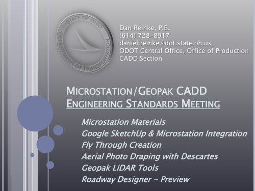
Dan Reinke, P.E.<br />
(614) 728-8917<br />
daniel.reinke@dot.state.oh.us<br />
ODOT Central Office, Office of Production<br />
CADD Section<br />
MICROSTATION/GEOPAK CADD<br />
ENGINEERING STANDARDS MEETING<br />
Microstation Materials<br />
Google SketchUp & Microstation Integration<br />
Fly Through Creation<br />
Aerial Photo Draping with Descartes<br />
Geopak LiDAR Tools<br />
Roadway Designer - Preview
Dan Reinke, P.E.<br />
(614) 728-8917<br />
daniel.reinke@dot.state.oh.us<br />
ODOT Central Office, Office of Production<br />
CADD Section<br />
MICROSTATION/GEOPAK CADD<br />
ENGINEERING STANDARDS MEETING<br />
Microstation Materials<br />
Google SketchUp & Microstation<br />
Integration
PRESENTATION OVERVIEW<br />
• What is a Material?<br />
• Material Editor<br />
o Material Tables<br />
o Material Palettes<br />
o Material Creation (Live Demo)<br />
o Material Application (Live Demo)<br />
o Material Manipulation (Live Demo)<br />
• Environment Maps (Live Demo)<br />
• Google 3D Warehouse Model Integration (Live Demo)
WHAT IS A MATERIAL?<br />
• Materials are used to make 3D Microstation<br />
objects look like the real world objects that<br />
they represent.
MATERIAL EDITOR<br />
• The material editor is where all material<br />
related functions are located.<br />
• It can be accessed from the “Rendering”<br />
toolbox. (Tools>Visualization>Rendering)
MATERIAL TABLES AND PALETTES<br />
• A Material Table (.mat) is a file containing all<br />
the various Material Palettes.<br />
• A Material Palette (.pal) is a file containing all<br />
the various material definitions.<br />
Material Table Name<br />
Material Definitions<br />
Material Palette Name
MATERIAL EDITOR (CONTINUED)<br />
• There are two modes;<br />
Advanced Mode On or Off<br />
Advanced Mode “On” Advanced Mode “Off”
MATERIAL CREATION, APPLICATION, AND<br />
MANIPULATION & ENVIRONMENT MAPPING<br />
• The creation, application, and manipulation<br />
of materials, environment mapping, and<br />
Google 3D Warehouse usage will be<br />
explained via a live demonstration in<br />
Microstation V8 XM Edition.
MICROSTATION/GEOPAK CADD<br />
ENGINEERING STANDARDS MEETING<br />
Dan Reinke, P.E.<br />
(614) 728-8917<br />
daniel.reinke@dot.state.oh.us<br />
ODOT Central Office, Office of Production<br />
CADD Section<br />
Questions?
MICROSTATION/GEOPAK CADD<br />
ENGINEERING STANDARDS MEETING<br />
Dan Reinke, P.E.<br />
(614) 728-8917<br />
daniel.reinke@dot.state.oh.us<br />
ODOT Central Office, Office of Production<br />
CADD Section<br />
Fly Through Creation
PRESENTATION OVERVIEW<br />
• What is a Fly Through?<br />
• Dialogue Box Overview and Definitions<br />
• Procedure Outline<br />
• Live Demonstration
WHAT IS A FLY THROUGH?<br />
• A fly through is a sequence of rendered<br />
images, or frames, strung together to create<br />
a movie, that can be used to represent a<br />
birds eye view of a project along any path<br />
that the user chooses.<br />
• The fly through producer is a tool that allows<br />
the user to generate an AVI file that can be<br />
viewed by anyone using only Windows Media<br />
Player or another compatible video player.
DIALOGUE BOX OVERVIEW & DEFINITIONS<br />
• Angle (Horizontal) – Sets the angle, in degrees,<br />
of the lens “field of vision”. Increasing the angle<br />
θ<br />
decreases the focal length.<br />
L<br />
• Focal Length (Horizontal) – Sets the lens “focal<br />
length”, in millimeters, to widen the lens “field of<br />
vision”. Decreasing the focal length increases<br />
the angle.<br />
• Front Clip Distance - Sets the distance along the<br />
view z-axis, in working units, to the plane at<br />
which the camera begins to “see” elements in<br />
the design. Any part of an element closer to the<br />
camera than this plane is not included in the<br />
frame. If the plane “clips” an element, the frame<br />
will show a “slice” of that element.<br />
• Back Clip Distance - Sets the distance along the<br />
view z-axis, in working units, to the plane<br />
beyond which the camera no longer “sees”<br />
elements in the design. Any element (or part of<br />
an element) further than this plane from the<br />
camera is clipped.
DIALOGUE BOX OVERVIEW & DEFINITIONS (CONT’D)<br />
• Target Position – Affects the definition of the<br />
“target” at which the camera points:<br />
o Fixed - The camera is always focused on the<br />
same point while moving along the camera<br />
path.<br />
o Floating - The camera always points in the<br />
direction tangent to the path.<br />
• Speed (ticks/frame) – Sets the number of ticks<br />
(1/60 th second) that each frame is displayed in<br />
the movie. (Only used in .FLI format)<br />
• Resolution (pixels) – Sets the size of the screen<br />
displayed in the movie. Higher resolutions will<br />
result in larger files, taking longer to create.<br />
• Gamma Correction - Sets the brightness of the<br />
images in the output file(s). The default value is<br />
1; the valid range is 0.1 to 3.0. Increasing the<br />
Gamma Correction setting lightens the images;<br />
decreasing it darkens the images.
DIALOGUE BOX OVERVIEW & DEFINITIONS (CONT’D)<br />
• Frame – This defines the number of frames that<br />
make up the movie. More frames will make the<br />
movie longer and “fly” slower, less frames will<br />
make the movie shorter and “fly” faster.<br />
o As a starting point, a smooth realistic<br />
“speed” for creating a fly through, note the<br />
following:<br />
0.122 frames/ft of camera path works<br />
well, and produces a smooth fly through.<br />
Example:<br />
Camera path = 1500 ft therefore;<br />
1500 ft * (0.122 frames/ft) =<br />
183 frames
PROCEDURE OUTLINE<br />
• Draw Camera Path<br />
• Open Fly Through Producer<br />
(Utilities>Render>Fly Through)<br />
• Populate Dialogue Box<br />
• Define Camera Path/Target<br />
• Preview<br />
• Record
LIVE DEMONSTRATION
MICROSTATION/GEOPAK CADD<br />
ENGINEERING STANDARDS MEETING<br />
Dan Reinke, P.E.<br />
(614) 728-8917<br />
daniel.reinke@dot.state.oh.us<br />
ODOT Central Office, Office of Production<br />
CADD Section<br />
Questions?
MICROSTATION/GEOPAK CADD<br />
ENGINEERING STANDARDS MEETING<br />
Dan Reinke, P.E.<br />
(614) 728-8917<br />
daniel.reinke@dot.state.oh.us<br />
ODOT Central Office, Office of Production<br />
CADD Section<br />
Aerial Photo Draping with<br />
Descartes
PRESENTATION OVERVIEW<br />
• What is aerial photo draping?<br />
• Requirements/Procedure Outline for draping<br />
with Descartes.<br />
• Live Demonstration
WHAT IS AERIAL PHOTO DRAPING?
COMPARISON:<br />
WITHOUT DRAPING
COMPARISON:<br />
WITH DRAPING
REQUIREMENTS/PROCEDURE OUTLINE FOR<br />
DRAPING WITH DESCARTES<br />
• Descartes installed. Five licenses currently<br />
available on server. (Image file size limitations<br />
draping with Microstation alone.)<br />
• Aerial image attached using Raster Manager<br />
• Aerial image properly located (horizontally)<br />
• “Draping” toggled on in Raster Manager<br />
• dcdrape.pal loaded and assigned in Material<br />
Editor<br />
• Render to verify results
LIVE DEMONSTRATION
MICROSTATION/GEOPAK CADD<br />
ENGINEERING STANDARDS MEETING<br />
Dan Reinke, P.E.<br />
(614) 728-8917<br />
daniel.reinke@dot.state.oh.us<br />
ODOT Central Office, Office of Production<br />
CADD Section<br />
Questions?
MICROSTATION/GEOPAK CADD<br />
ENGINEERING STANDARDS MEETING<br />
Dan Reinke, P.E.<br />
(614) 728-8917<br />
daniel.reinke@dot.state.oh.us<br />
ODOT Central Office, Office of Production<br />
CADD Section<br />
Geopak LiDAR Tools
PRESENTATION OVERVIEW<br />
• Description of new Geopak LAS tool<br />
• Location of North Zone OSIP LAS data<br />
• Overview of steps to create TIN model from LAS data<br />
• Live demo of TIN creation from LAS data
GEOPAK LAS TOOL<br />
• Geopak XM, Service Pack 1, version 08.09.05.36<br />
• LAS tool is located in “LIDAR XYZ Tools” within<br />
Geopak DTM tools.<br />
• Creates binary XYZ file as an output.<br />
• Horizontal location of LAS data will not line up<br />
initially when overlaid on ground survey.<br />
Suspected Grid to Ground issue.
LOCATION OF NORTH ZONE OSIP LAS DATA<br />
• LAS Data location<br />
o //itcfs007/gdrive/GEOMEDIA/warehouses/images/<br />
osip/lidar/”county”<br />
• Mr. SID Imagery location<br />
o //itcfs007/gdrive/GEOMEDIA/warehouses/images/<br />
imagery/North<br />
• LAS Data location on OGRIP website<br />
o http://gis3.oit.ohio.gov/geodata/<br />
o Note: Internet Explorer usually cannot handle the size of<br />
the downloads, so Firefox or Opera could be used. All<br />
data can be obtained on the G: drive so web interface<br />
should not be needed typically.<br />
• Information regarding OSIP program and status<br />
o http://ogrip.oit.ohio.gov/ServicesData/<br />
StatewideImagery/tabid/86/Default.aspx
OVERVIEW OF STEPS TO CREATE TIN MODEL<br />
FROM LAS DATA<br />
• Locate and copy LAS tiles for area in question<br />
o A Microstation .dgn file has been posted on the<br />
Central Office Production FTP site which contains<br />
each tile location along with county/district<br />
boundaries and roadways.<br />
o Central Office Production FTP site address<br />
ftp://ftp.dot.state.oh.us/pub/Production/OSIP_LAS_Tile<br />
s/OSIP_Tiles.dgn
OVERVIEW OF STEPS TO CREATE TIN MODEL<br />
FROM LAS DATA (CONTINUED)
OVERVIEW OF STEPS TO CREATE TIN MODEL<br />
FROM LAS DATA (CONTINUED)<br />
• Open “LIDAR XYZ Tools” in Geopak<br />
• Convert LAS file to binary XYZ (Use “Ground” feature)<br />
o Select input file (LAS), and define output file (XYZ)<br />
• Convert XYZ file to TIN file<br />
o Select input file (XYZ), and define output file (TIN)
LIVE DEMONSTRATION
MICROSTATION/GEOPAK CADD<br />
ENGINEERING STANDARDS MEETING<br />
Dan Reinke, P.E.<br />
(614) 728-8917<br />
daniel.reinke@dot.state.oh.us<br />
ODOT Central Office, Office of Production<br />
CADD Section<br />
Questions?