
Create successful ePaper yourself
Turn your PDF publications into a flip-book with our unique Google optimized e-Paper software.
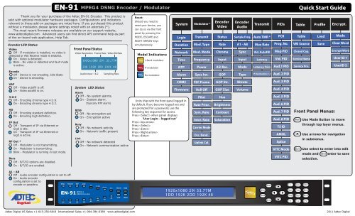
Thank you for your purchase of the Adtec EN-91 Encoder. This product is<br />
sold with optional modulator hardware packages. Configurations and indicators<br />
relevant to those add-on packages are noted here. If you purchased this product<br />
without a modulator, please ignore settings noted with an asterisks (*).<br />
The most recent firmware releases are available on our support website,<br />
www.adtecdigital.com. Advanced users can find direct API command help as part<br />
of the on-board web application, Help Tab.<br />
Encoder LED Status<br />
Video<br />
Off - If modulator is installed, no video is<br />
detected or ASI Receive mode is enabled.<br />
On - Video is detected.<br />
Blink - No video is detected and fault mode<br />
is active.<br />
Encode<br />
Off - Device is not encoding. Idle State<br />
On - Device is encoding.<br />
VAF<br />
Off - Video autofill is off.<br />
On - Video autofill is on.<br />
4:2:2<br />
Off - Encoding chroma type 4:2:0.<br />
On - Encoding chroma type 4:2:2.<br />
HD<br />
Off - Encoding standard definition.<br />
On - Encoding high definition.<br />
IP Out<br />
Off - Transport of IP via Ethernet or<br />
GigE is idle.<br />
On - Transport of IP via Ethernet or<br />
GigE is active.<br />
RF Out *<br />
Off - Modulator is not transmitting.<br />
On - Modulator is transmitting.<br />
Blink - Modulator is running in test mode.<br />
Bars<br />
Off - B/T/ID options are disabled.<br />
On - B/T/ID are enabled.<br />
A1 - A8<br />
Off - Audio encoder configuration is set to off.<br />
On - Audio encoder<br />
configuration is set to<br />
encode or passthru.<br />
91<br />
MPEG4 DSNG Encoder / Modulator<br />
Front Panel Status<br />
Video Resolution Frame Rate Video Bit Rate<br />
System LED Status<br />
Alarm<br />
Off - No system alarms.<br />
On - System alarm.<br />
(Typically NTP alarm)<br />
BISS<br />
Off - No encryption set<br />
On - Encryption active<br />
Busy<br />
Off - No network activity<br />
On - Network traffic present<br />
Link<br />
Off - No network detected<br />
On - Network communication active<br />
VAF<br />
1920x1080 29i 33.77M<br />
1DD 192K 2DD 192K 48<br />
Audio Input 1 & 2 Sampling Rate<br />
MPEG 4<br />
91 DSNG Encoder<br />
HD<br />
A5<br />
IP Out<br />
A6<br />
RF Out<br />
A7<br />
Bars<br />
A8<br />
Reset:<br />
Should you need to<br />
reset your device, you<br />
can do so via the front<br />
panel by pressing the<br />
MODE, ESCAPE and<br />
RIGHT ARROW keys<br />
simultaneously.<br />
Model Indicators:<br />
L-Band modulator<br />
IF modulator<br />
No modulator<br />
System<br />
Login<br />
Duration<br />
Network<br />
Units ship with the front panel logged in<br />
by default. If you become logged out and<br />
are prompted for a password, use the<br />
following key sequence for access.<br />
Press when panel displays<br />
‘User Login -- logged out’<br />
Press <br />
Press <br />
Press <br />
Press <br />
Press <br />
1920x1080 GOOD 20.000M 29i 33.77M ASI 00001 AdtecDigital<br />
1DD 1920x1080 192K 2DD 29i 192K AC 48<br />
MU MU MU -- -- -- -<br />
<strong>Quick</strong> <strong>Start</strong> <strong>Guide</strong><br />
Front Panel Menus:<br />
Use Mode Button to move<br />
through top layer menus.<br />
Use arrows for navigation<br />
in submenus.<br />
Use select to enter into edit<br />
mode and ENTER enter to save<br />
selection.<br />
Adtec Digital US Sales +1-615-256-6619 International Sales +1-904-394-0389 www.adtecdigital.com 2011 Adtec Digital<br />
Time<br />
NTP<br />
Alarm<br />
COM2<br />
Firmware<br />
Modulator *<br />
Transmit<br />
Mod. Type<br />
Mod. Mode<br />
Frequency<br />
Power<br />
Spec Inv.<br />
FEC Frame<br />
Roll O<br />
Pilot<br />
Rate Prior.<br />
Sym. Rate<br />
Inter. Rate<br />
Carrier Mode<br />
Occ. Band.<br />
Uplink Cal.<br />
Encoder<br />
Video<br />
Status<br />
Rate<br />
Chroma<br />
Input<br />
ASI Rec.<br />
GOP<br />
GOP Str.<br />
GOP Size<br />
Hue<br />
Brightness<br />
Contrast<br />
Saturation<br />
Encoder<br />
Audio<br />
Sample Freq.<br />
A1 - A8<br />
Sync<br />
Input<br />
Mode<br />
Type<br />
Bitrate<br />
Volume<br />
Transmit PIDs Table Prole<br />
Auto TMR *<br />
Mux Rate<br />
Vid. AutoFill<br />
Latency<br />
Latency Trim<br />
IP Destinations 1-4<br />
SELECT<br />
ENTER<br />
MODE<br />
ESCAPE<br />
PCR<br />
Prog. No.<br />
Map PID<br />
Vid. PID<br />
Aud.1 PID<br />
Aud. 2 PID<br />
Aud. 3 PID<br />
Aud. 4 PID<br />
Aud. 5 PID<br />
Aud. 6 PID<br />
Aud. 7 PID<br />
Aud. 8 PID<br />
TS ID<br />
AMOL<br />
Splice<br />
VITC Mode<br />
VITC PID<br />
Table<br />
VBI Source<br />
Closed Cap.<br />
Service Name<br />
Service Prv.<br />
MODE<br />
SELECT<br />
1 2abc 3def<br />
4ghi<br />
5jkl<br />
6mno<br />
7pqrs 8tuv 9wxyz<br />
F1 0 F2<br />
Load<br />
Save<br />
Encrypt.<br />
Mode<br />
Clear Word<br />
Encrypt Word<br />
User ID 1<br />
UserID 2
Getting Connected Web-Based Control Application<br />
Adtec Digital has adopted<br />
To begin, you will need to connect to your EN-91 via ethernet<br />
directly, or by adding the EN-91 to your local area network.The default<br />
address for all Adtec devices is 192.168.10.48.<br />
To connect directly to the device, make sure that your computer<br />
and the device have IP addresses within the same IP class range (ex.<br />
192.168.10.48 for the device and 192.168.10.49 for your computer).<br />
If you need to change the IP address of the device, this can be done via<br />
the front panel, System > Network menu. Using a CAT 5 crossover<br />
cable, connect one end to your computer and the other to the Ethernet<br />
port found on the processor section of the back panel. (Some computers<br />
can auto negotiate the connection and a crossover may not be<br />
necessary.)<br />
To add the device to a LAN, connect a standard CAT 5 Ethernet<br />
cable to your network router and then to the Ethernet port on the back<br />
of the device. If your network is DHCP enabled and you prefer that over<br />
a static IP, you can turn on DHCP for the device via the front panel,<br />
System > Network menu.<br />
Power ...............................................................................................................................<br />
Power 1 & 2 Redundant AC Power, Standard 3 pin computer power plug<br />
(Auto range 70-240 VAC Input)<br />
Modulator (optional)*............................................................................................<br />
Main RF output, 50 Ohm BNC<br />
L-Band Model: Frequency range 950 MHz to 1.750 GHz, Power Level -50 to -7 dBm<br />
IF Model: Frequency range 50 MHz to 180 MHz, Power Level -30 to +5 dBm<br />
Monitor RF output, 50 Ohm BNC<br />
L-Band Model: Fixed power level at -45 dBm<br />
IF Model: Fixed power level at -45 dBm, xed frequency at 1.08 GHz<br />
10MHz Clock BNC 50 Ohm connector for external 10MHz reference input<br />
Processor ......................................................................................................................<br />
GigE MPEG2 or RTP multicast transport egress port (SMPTE 2022)<br />
COM2 API Serial Communication Interface<br />
COM1 Serial Port Used for Troubleshooting (Terminal)<br />
Ethernet 10/100 base T ethernet interface (Monitoring/Management)<br />
DVC Parport 9-pin parallel I/O interface for control systems<br />
RS422 Not Currently Supported<br />
GPIO Tally and Control Port<br />
Encoder.........................................................................................................................<br />
ASI OUT 75 Ohm source ASI x3 per EN5000839. Up to 100 Mbps.<br />
CVBS In 75 Ohm terminated Standard Denition Composite Video Input<br />
SDI In 75 Ohm terminated Input, Video & Audio (SMPTE 259M for SD & SMPTE 292M for HD) BNC<br />
AES Audio In 1-4 75 Ohm AES-3 per AES3-2003<br />
Analog Audio In Stereo Pairs 1 and 2 (600 Ohm Balanced)<br />
1<br />
zero-conguration networking<br />
technology, streamlining the setup and<br />
conguration processes for our products.<br />
The use of this technology enables<br />
automatic discovery of Adtec devices and<br />
services on an IP network. Used in tandem<br />
with the web-based control and<br />
conguration applications we can now<br />
provide 1-click access to any device.<br />
By using the built-in Bonjour © locater in<br />
Apple's © Safari © browser or the plug-ins<br />
readily available for IE © or Firefox ©<br />
browsers, users can locate all of the Adtec<br />
devices on a network by referencing the<br />
serial number on the back of the device. Clicking on the unit in the Bonjour © Have<br />
?<br />
list will re-route you to a<br />
login page. If you do not wish to use Bonjour, you can reach the device’s web application by pointing<br />
your browser to the IP Address of the device. Ex. http://192.168.10.48/. You will be prompted for a<br />
username and password. The default username is ‘adtec’. The default password is ‘none’.<br />
The left-hand panel of the application will report current status in real-time while the right<br />
panel tabs will allow you to congure your device.<br />
Power<br />
2<br />
Main<br />
Modulator<br />
Monitor<br />
GigE<br />
10Mhz<br />
Clock<br />
COM2<br />
COM1<br />
Ethernet<br />
Processor<br />
questions? Each field or group of fields in<br />
our web-based application has a hint button associate<br />
with it. It contains information on use of the field or<br />
acceptable ranges.<br />
Getting <strong>Start</strong>ed<br />
Once your encoder is accessible via network, you can<br />
set it up for transmission. You will need to adjust the<br />
configurations using the front panel or web UI. As you make<br />
changes, you will see the status sections on the left hand side of<br />
the web UI adjust. These status<br />
sections report the majority of the<br />
critical information needed for<br />
monitoring during a transmission. Each<br />
of these status menus can be collapsed<br />
by clicking on the icon. This allows<br />
you to view only that information which<br />
is most critical for you, but keeps a<br />
LED indicator visible for all sections at<br />
all times for alarms.<br />
Encoding Status: These values<br />
indicate the encoder’s state and<br />
displays alarms when a video loss<br />
event is detected.<br />
Service Data: These values indicate<br />
the service or program data being used<br />
in your transmission as well as the<br />
total TMR output.<br />
* Modulator Status: Devices<br />
containing the optional modulator will<br />
display this status window indicating<br />
activity and critical uplink parameters.<br />
IP Status: These values indicate the<br />
status of IP Egress including address,<br />
port and FEC parameters.<br />
Video Status: The video status<br />
information is auto-detected per the<br />
input selected. Information such as<br />
resolution, chroma, framerate and<br />
video rate are included.<br />
Audio Status: This section will display<br />
all audio status including bitrate,<br />
format and audio input selected.<br />
Adtec Digital Technical Support: 615.256.6619 www.adtecdigital.com 08.26.11<br />
DVC Parport<br />
ASI Out X 3<br />
RS422<br />
C VBS In<br />
SDI In<br />
GPIO<br />
AES Audio<br />
In 1-4<br />
Analog Audio<br />
>>