

Issue 17 - Free-Energy Devices
Issue 17 - Free-Energy Devices
Issue 17 - Free-Energy Devices

You also want an ePaper? Increase the reach of your titles
YUMPU automatically turns print PDFs into web optimized ePapers that Google loves.
can be transformed into a magnetic perpetual<br />
motion machine. This ME is shown in Fig. 6.<br />
To improve the gravity application in the MGE,<br />
we worked out a “magnetic whirligig” device,<br />
where constant magnets perform back-andforth<br />
motion (Fig. 6).<br />
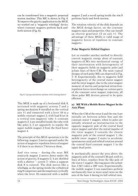
Fig. 6. A perpetual motion machine with rotating shutter<br />
This MGE is made up of a horizontal disk 8,<br />
sectioned with magnetic screens 7 and a<br />
spring mechanism 9 installed on the vertical<br />
axis 11 and connected with a lever 10 to a<br />
mobile constant magnet 2, with load 6 set in<br />
a vertical non-magnetic tube 1; constant<br />
magnets 2, 4 are installed inside the tube with<br />
like poles 3, 5 set oppositely to repulse the<br />
upper mobile magnet 2 from the fixed lower<br />
magnet 4.<br />
The principle of this MGE operation is in the<br />
following: magnet 2 moves upward under the<br />
action of magnetic repulsion forces of magnet<br />
4 if there is no shutter 7 between them.<br />
And vice versa – during the next ME<br />
semicycle magnet 2 moves down under the<br />
action of gravity, if magnets 2, 4 are shielded<br />
with a shutter – screen 7- when a segment<br />
disk 8 is rotated. The disk moves like a<br />
whirligig, as the spring inside the cylindrical<br />
ring 9 compresses and decompresses cyclically<br />
when the lever 10 connected with a mobile<br />
magnet 2 and a recoil spring inside the rim 9<br />
performs back-and forth motion.<br />
The rotation velocity of the disk depends on<br />
the MGE design factor, on the constant<br />
magnets mass and properties. One can install<br />
an electric generator 12 on axis 11. The<br />
advantage of these MGEs is valid usage of<br />
magnetic forces of repulsion in constant<br />
magnets.<br />
Polar Magnetic Orbital Engines<br />
Let us consider another method to directly<br />
convert magnetic energy alone of constant<br />
magnets (CM) into mechanical energy of<br />
their interrotation with heterogeneity of<br />
their magnetic fields on magnetic poles and<br />
aclinic lines of there CM. The most typical<br />
designs of such polar MEs are depicted in Fig.<br />
7- 9. Experimentally, due to magnetic field<br />
heterogeneity of the central stator magnet<br />
and the rotor magnet, due to the rotor magnet<br />
moment of inertia and perpetual attractionrepulsion<br />
forces interchange on various parts<br />
of the constant rotor magnet trajectory, all<br />
these polar ME devices proved to be quite<br />
efficient.<br />
a) ME With a Mobile Rotor Magnet In the<br />
Axis Plane<br />
When the CM of the rotor 2 and the rim 3 are<br />
initially set between aclinic line and the<br />
constant stator 1 magnet, when its poles are<br />
initially oriented on interattraction to the<br />
opposite magnetic pole of the central fixed<br />
stator magnet and after the initial impulse of<br />
the rotor magnet 2 towards the closest<br />
magnetic pole of the central magnet 1, the<br />
mobile rotor- magnet 2 starts to accelerate<br />
spontaneous axial and orbital rotation around<br />
the central fixed constant magnet 1 in the<br />
upper dead point.<br />
It mechanically passes the area above the<br />
magnetic pole of the central CM and, with its<br />
lines of force, repulses from the like pole of<br />
the stator 1 magnet. Having passes the aclinic<br />
line, CM 1 takes a 180° turn. Experimentally,<br />
the mobile magnet 2 can sometimes perform<br />
mechanically four or more axial turns on the<br />
axis of the base 4 during its full orbital turn.<br />
54 New <strong>Energy</strong> Technologies, <strong>Issue</strong> #3(18) 2004


