Issue 17 - Free-Energy Devices
Issue 17 - Free-Energy Devices Issue 17 - Free-Energy Devices
Fig.5 Pendulum Wheel Fig. 6 shows a wooden model of an asymmetric pendulum designed by Prof. Evert. In some phases of its work the process coincides with theory perfectly, but the device doesn’t function properly and can’t be in constant motion. Fig. 7 presents a structure of 3 pendulums set on one rotor. Theoretically the system is self- accelerating, but only up to a Fig.6.1 Fig.6.2 definite speed. Prof. Evert considers this attempt to be a prospective and interesting enough. To obtain a positive result one should design a model with better quality. 36 New Energy Technologies, Issue #3(18) 2004 Fig.7
Bessler’s Wheel Fig. 8 is photo of the wooden model, tested by Prof. Evert in his laboratory. The model is constructed of the most primitive materials. The theoretically expected effects are really visible. But the problem of this model is the fact, that the spring is not compressed at once, and this delay influences the work of the system. Fig.8.1 Fig.8.2 New Energy Technologies, Issue #3 (18) 2004 Sun Wheel Fig. 9 shows the operational principle of another device suggested by Prof. Evert. Fig.11 The variations of this principle are Fig. 10. Fig.10 The minimal possible number of working elements is three, as it’s shown in Fig. 11. Turbines Fig. 12 illustrated the scheme of the turbine suggested by Prof. Evert. The inlet of water is performed in the centre of the system, axially. Pay your attention to the original form of the stator. 37
- Page 5 and 6: New Energy Technologies Magazine Sc
- Page 7 and 8: understanding that any matter is a
- Page 9 and 10: Fig.3. This is an autonomous 50 KW
- Page 11 and 12: In the nearest time VHG already wil
- Page 13 and 14: New Energy Technologies, Issue #3 (
- Page 15 and 16: A cylindrical carbon-steel magnet M
- Page 17 and 18: has), that is possibly organized in
- Page 19 and 20: Fig.4 inertor’s efficiency lays i
- Page 21 and 22: The palnet Earth is a natural elect
- Page 23 and 24: this unipolar induction the total i
- Page 25 and 26: 3. From the experiments on the firs
- Page 27 and 28: principle of functioning of such al
- Page 29 and 30: New Energy Technologies, Issue #3 (
- Page 31 and 32: Na = Na + + е - (К 1 = 9,9 х 10
- Page 33 and 34: and with an electric motor on a spi
- Page 35 and 36: Fig.1 1 - the well; 2 - the pumping
- Page 37 and 38: The semiconductor transformator of
- Page 39: Oscillation Motor Fig. 2 presents a
- Page 43 and 44: Fig.16 The basic construction of th
- Page 45 and 46: discovering a means to move a vehic
- Page 47 and 48: The phenomenon of quantum tunneling
- Page 49 and 50: esearch by the Naval Research Labs
- Page 51 and 52: such as the British Aerospace Syste
- Page 53 and 54: Concept", PL-TR-91-3009, Final Repo
- Page 55 and 56: like “samarium- cobalt” are use
- Page 57 and 58: epulsion increases and the process
- Page 59 and 60: Fig. 7. Magnetic orbital engine wit
- Page 61 and 62: On Physical Essence of Magnetic Ene
- Page 63 and 64: polarity, stator means mounted in o
- Page 65 and 66: interconnections established throug
- Page 67 and 68: field as in the case of the rotor s
- Page 69 and 70: the altering distance to the rotati
- Page 71 and 72: mass rotation in the involved secti
- Page 73 and 74: Date: Wed, 11 Aug 2004 Permanent ma
- Page 75 and 76: Transient Transient Currents Curren
- Page 77 and 78: OVER UNITY PROPULSION OF A ZERO POT
- Page 79 and 80: well. The aspect that, according to
- Page 81 and 82: Because of the fact that the elemen
- Page 83 and 84: change. In a moving charge within a
- Page 85 and 86: For that it is necessary to create
- Page 87 and 88: all this makes the generator one of
- Page 89 and 90: we’re opposed to conventional sci
Fig.5<br />
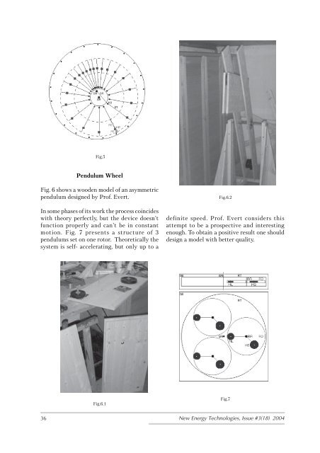
Pendulum Wheel<br />
Fig. 6 shows a wooden model of an asymmetric<br />
pendulum designed by Prof. Evert.<br />
In some phases of its work the process coincides<br />
with theory perfectly, but the device doesn’t<br />
function properly and can’t be in constant<br />
motion. Fig. 7 presents a structure of 3<br />
pendulums set on one rotor. Theoretically the<br />
system is self- accelerating, but only up to a<br />
Fig.6.1<br />
Fig.6.2<br />
definite speed. Prof. Evert considers this<br />
attempt to be a prospective and interesting<br />
enough. To obtain a positive result one should<br />
design a model with better quality.<br />
36 New <strong>Energy</strong> Technologies, <strong>Issue</strong> #3(18) 2004<br />
Fig.7


