Clack WS2H-WS3 Programming manual - Dime WATER
Clack WS2H-WS3 Programming manual - Dime WATER
Clack WS2H-WS3 Programming manual - Dime WATER

You also want an ePaper? Increase the reach of your titles
YUMPU automatically turns print PDFs into web optimized ePapers that Google loves.
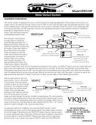
Water Specialist<br />
<strong>WS2H</strong> and <strong>WS3</strong> Control Valve<br />
<strong>Programming</strong> and Wiring Manual
Table of Contents<br />
General Information ...........................................................................................................4<br />
Software and Power Supply Compatibility ......................................................................... 5<br />
Wiring for Custom AC Adapter and Custom Meter Wiring ............................................... 6<br />
PC Board layout .................................................................................................................. 7<br />
Optional System PC Board Relay 1 and 2, and Separate Source drive connections .......... 9<br />
Motorized Drive Operations ............................................................................................... 9<br />
Wiring and System Confi guration Guides ........................................................................ 10<br />
Quick Reference <strong>Programming</strong> Screens ........................................................................... 20<br />
User Screens ...................................................................................................................... 22<br />
Setting Time of Day .......................................................................................................... 23<br />
System Setup Screens ....................................................................................................... 24<br />
Cycle Setup Screens .......................................................................................................... 27<br />
Timer Screens ................................................................................................................... 29<br />
Installer Setup Screens ...................................................................................................... 31<br />
Diagnostic Screens ............................................................................................................ 32<br />
Valve History .................................................................................................................... 34
Page 4 <strong>WS2H</strong> and <strong>WS3</strong> <strong>Programming</strong> and Wiring Manual<br />
Table 1<br />
General Specifi cations and Pre-Installation Checklist<br />
Minimum/Maximum Operating Pressures 20 psi (138 kPa) -125 psi (862 kPa)<br />
Minimum/Maximum Operating<br />
Temperatures<br />
40°F (4°C) – 110°F (43°C)<br />
Power Adapter:<br />
Supply Voltage<br />
Supply Frequency<br />
Output Voltage<br />
Output Current<br />
Service fl ow rate<br />
Backwash fl ow rate<br />
CV Service<br />
CV Backwash<br />
Meter:<br />
Accuracy<br />
Flow Range<br />
U.S.<br />
120V AC<br />
60 Hz<br />
20V or 24V AC see Table 2<br />
800 mA<br />
International<br />
230V AC<br />
50 Hz<br />
20V or 24V AC<br />
800 mA<br />
No user serviceable parts are on the PC board, the motor, or the Power adapter. The means of<br />
disconnection from the main power supply is by unplugging the Power adapter from the wall.<br />
<strong>WS2H</strong> Valve: 125 gpm (473 lpm, 28.4 m 3 /h) @ 15 psig (103 kPa) drop<br />
<strong>WS3</strong> Valve: 250 gpm (946 lpm, 56.8 m 3 /h) @ 15 psig (103 kPa) drop<br />
<strong>WS2H</strong> Valve: 125 gpm (473 lpm, 28.4 m 3 /h) @ 25 psig (172 kPa) drop<br />
<strong>WS3</strong> Valve: 220 gpm (833 lpm, 50.0 m 3 /h) @ 25 psig (172 kPa) drop<br />
<strong>WS2H</strong> Valve: 32.3<br />
<strong>WS3</strong> Valve: 64.6<br />
<strong>WS2H</strong> Valve: 25.0<br />
<strong>WS3</strong> Valve: 44.0<br />
<strong>WS2H</strong> Valve: Internal Meter<br />
+ 5 %<br />
1.5 – 125 gpm (5.7 – 473 lpm)<br />
<strong>WS3</strong> Valve: Optional External Meter<br />
+ 5 %<br />
3.5 – 350 gpm (13.3 – 1325 lpm)<br />
Regenerant Refi ll Rate<br />
<strong>WS2H</strong> and <strong>WS3</strong> Valves: Variable - Shipped from Factory with 2.2 gpm<br />
(8.33 lpm)<br />
Injectors <strong>WS2H</strong> & <strong>WS3</strong> Valves: See Injector Graphs V3010-2A through 2H<br />
Brine Line Adapters Included 1” Male NPT Elbow & ¾” x 1” Solvent Weld Elbow<br />
Inlet, Outlet and Drain Line Openings<br />
Distributor Tube Opening:<br />
<strong>WS2H</strong> Valve<br />
<strong>WS3</strong> Valve<br />
Tank Connection:<br />
<strong>WS2H</strong> Valve<br />
<strong>WS3</strong> Valve<br />
Shipping Weight<br />
PC Board Memory<br />
Compatible with the following typical<br />
concentrations of regenerants/chemicals<br />
<strong>WS2H</strong> Valve: 2” Female NPT or BSPT or 2.5” Groove Lock<br />
<strong>WS3</strong> Valve: 3” Female NPT or BSPT, No Groove Lock<br />
Female NPT Inlet & Outlet<br />
2.375” OD (2.0” NPS)<br />
3.5” OD (3” NPS)<br />
Female BSPT Inlet & Outlet<br />
63 mm OD<br />
90 mm OD<br />
4”-8UN, 6” Flange, Side Mount (2” Female NPT or BSPT or 2.5” Groove Lock)<br />
6” Flange or Side Mount (3” Female NPT or BSPT)<br />
<strong>WS2H</strong> Valve with Meter: 50 lbs (22.7 kg)<br />
<strong>WS3</strong> Valve: 57 lbs (25.9 kg) Meter Sold Separately<br />
Nonvolatile EEPROM<br />
(electrically erasable programmable read only memory)<br />
Sodium chloride, potassium chloride, potassium permanganate, sodium bisulfi te,<br />
chlorine and chloramines
<strong>WS2H</strong> and <strong>WS3</strong> <strong>Programming</strong> and Wiring Manual Page 5<br />
V3242-01BOARD Main<br />
Board1 114.10<br />
114.11<br />
115.17<br />
115.25<br />
200.01<br />
215.02<br />
215.03<br />
215.04<br />
Software Version Power Supply<br />
V3243-01BOARD<br />
System Board<br />
1.03<br />
1.07 or 1.08<br />
1.11 or 1.13<br />
215.10 1.11 or 1.13<br />
Table 2<br />
Software and Power Supply Compatibility<br />
Output<br />
Voltage<br />
24 VAC<br />
24 VAC<br />
20 VAC 3<br />
Part # and Description<br />
V3461 2 <strong>WS2H</strong>/3 AC ADAPTER<br />
V3461EU <strong>WS2H</strong>/3 AC ADAPTER EU<br />
V3461UK <strong>WS2H</strong>/3 AC ADAPTER UK<br />
V34612 <strong>WS2H</strong>/3 AC ADAPTER<br />
V3461EU <strong>WS2H</strong>/3 AC ADAPTER EU<br />
V3461UK <strong>WS2H</strong>/3 AC ADAPTER UK<br />
V3461-01 <strong>WS2H</strong>/3 AC ADAPTER 20V<br />
V3461EU-01 <strong>WS2H</strong>/3 AC ADAPTER EU 20V<br />
V3461UK-01 <strong>WS2H</strong>/3 AC ADAPTER UK 20V<br />
1It is recommended to maintain one version throughout a system.<br />
2Replacement V3461 power supplies have screw terminals and are shipped less a cord. Use cord from existing power supply to connect to the screw terminals.<br />
3 V3461EU-01 and V3461UK-01 will not be available for sale until August 2010.
Page 6 <strong>WS2H</strong> and <strong>WS3</strong> <strong>Programming</strong> and Wiring Manual<br />
Set clock from any USER fi eld.<br />
Recommended System Setup Sequence:<br />
1. Connect all wiring and communication cables.<br />
2. Apply power.<br />
3. Enter system setup screens and set screen 2 to number of units in the particular system.<br />
a. Setting this valve assigns master status to that unit.<br />
b. The master unit will establish communication with the remaining units and transfer the remaining settings to<br />
them.<br />
4. Set cycle sequence.<br />
5. Set cycle times.<br />
6. Set installer data.<br />
Wiring for custom AC Adapter<br />
1. See Table 2 Software and Power Supply Compatibility.<br />
2. Cable should be one unshielded pair of 22AWG, UV resistant UL2464<br />
compliant wire.<br />
3. Connector details:<br />
a. Terminate end with one Molex white housing,<br />
P/N 09-50-8043 and four Molex pins, P/N 08-50-0108.<br />
b. Pin 1 = AC from power supply (White)<br />
Pin 2 = Jumper to Pin 3<br />
Pin 3 = Jumper to Pin 2<br />
Pin 4 = AV from power supply (Black)<br />
Molex<br />
Housing<br />
Pin 1<br />
Custom Meter Wiring:<br />
Medium Reset<br />
From User 1 Screen - Volume Remaining<br />
Press and hold the Set Clock and Regen buttons for 10 seconds to reset valve<br />
to factory default programming. History and Diagnostics are not changed.<br />
1) Terminate end with a Molex series 2695 housing, part number 22-<br />
01-3037 and (3) Molex series 41572 (or 40445) pins, part number<br />
08-65-0805 (or 97-00-44).<br />
2) Auxilliary meter must be able to operate on 5VDC<br />
Pin 1 = +5VDC,<br />
Pin 2 (Center) = Signal<br />
Pin 3 = Ground<br />
3) Acceptable pulse input is .1 – 999 pulses/gallon, or<br />
.4 –519 pulses / liter.<br />
a
<strong>WS2H</strong> and <strong>WS3</strong> <strong>Programming</strong> and Wiring Manual Page 7<br />
1) Power Supply<br />
2) Manual Override Switch<br />
3) Flow<br />
Meter<br />
4) Motorized<br />
Alternating<br />
Valve<br />
9) Drive<br />
Motor<br />
Main PC Board with System Board<br />
5) POD<br />
Display<br />
Connection<br />
8) Communication<br />
Port<br />
10) System Board<br />
Connection<br />
6) Auxiliary<br />
Input<br />
7) <strong>Programming</strong><br />
Port<br />
11) <strong>Programming</strong><br />
Port<br />
11) Auxiliary<br />
Drive 13) Relay 2 12 ) Relay 1<br />
14) Communication Ports<br />
1) Unit’s main power supply. Labeled POWER.<br />
2) Isolation valve <strong>manual</strong> override switch will force the unit on-line or off-line. The corresponding LED indicator on the display<br />
POD will fl ash rapidly, 2 times per second, to warn that the unit is in a forced state.<br />
3) Flow meter input. Labeled FLOW.<br />
4) Drive circuit for Motorized Alternating Valve (MAV) or for a Motorized Bypass valve (V3060). It will bring a unit on-line or<br />
off-line based on the programming of the current system. Labeled BYPASS.<br />
5) POD connection for the display. This connection is also used as the data extraction port with the proper software and cabling.<br />
6) Auxiliary Input to control/ trigger when or how a unit can regenerate based on the setting of the dP screen in the programming<br />
setup. External inputs should be dry contacts and units wired in parallel require matching each unit’s polarity. Labeled AUX<br />
INPUT.<br />
7) <strong>Programming</strong> port connection for Main PC Board is for factory use only.<br />
8) Main board communication port can be used as the communication port for a 2 unit master and is the communication port for<br />
every slave unit of a system. Labeled MASTER/ SLAVE.<br />
9) Drive Motor circuit power the motor that drives the piston during regeneration. Labeled REGEN.<br />
10) Connection for Optional System Board. This board would be added to units requiring the extra drive circuit to operate a<br />
separate source valve, if a 2, 3, or 4 unit progressive fl ow/ alternator system was needed, or when relays would need to operate<br />
external devices. Labeled SYSTEM BOARD.<br />
11) Auxiliary Drive circuit is used to operate a Motorized Alternating Valve (MAV) based on the program setting of the separate<br />
source inlet on or off. This drive circuit is timed to sequence after a unit is isolated from a system, or prior to regen for units<br />
with no isolation. Labeled AUX DRIVE.<br />
12) Dry contact outputs to operate external devices based on the program setting of Relay 1. Labeled AUX 1.<br />
13) Dry contact outputs to operate external devices based on the program setting of Relay 2. Labeled AUX 2.<br />
14) Additional communication ports used on the master control valve for systems with 3 or 4 units. See wiring diagrams for<br />
examples. Labeled SLAVE 1, SLAVE 2, and SLAVE 3.
Page 8 <strong>WS2H</strong> and <strong>WS3</strong> <strong>Programming</strong> and Wiring Manual<br />
Revised communication cable connectivity.<br />
Communication Cable Connection to PC Board Layout<br />
View Of Revised 3 Wire Communication<br />
Cable On 4 Terminal Header<br />
3 Wire Cables Being Installed On 4<br />
Terminal Headers Need Left Polarizer<br />
"Ear" Removed<br />
Remove<br />
Ear<br />
Install cable flush to the<br />
right side leaving left terminal<br />
pin with no connection<br />
C<br />
View Of 4 Wire Communication Cable On 3<br />
Terminal Header (System Board Is Optional)<br />
A<br />
Install right side of cable flush<br />
to terminal leaving a vacant<br />
position on the left of the cable
<strong>WS2H</strong> and <strong>WS3</strong> <strong>Programming</strong> and Wiring Manual Page 9<br />
Separate<br />
Source Inlet<br />
Motor Drive<br />
Motorized Drive Operation<br />
Viewing the piston rod through the clear dome<br />
is a visual indicator of the drive’s current<br />
position. On the WS2 motorized bypass<br />
drive, viewing the rod indicates that the unit<br />
is in service. Viewing the rod as shown on<br />
the MAV indicates that the common port is<br />
currently connected to the “B” port. If the<br />
rod is not visible the unit is offl ine in the case<br />
of a bypass, or the common port is currently<br />
connected to the “A” port of a MAV. In this<br />
state the “B” port of a MAV is shut off. This<br />
drive logic is reversible to meet specifi c<br />
plumbing applications by reversing the polarity<br />
of the drive motor wiring harness as shown<br />
below.<br />
Push in Locking Tab<br />
While Pulling On Wire<br />
Relay 2 Relay 1<br />
Factory Wired<br />
As White Wire<br />
Optional System Board, Required For Relay Output And<br />
Separate Source Inlet<br />
1) Relay outputs 1 & 2 have N.O., N.C. and common dry<br />
contacts.<br />
2) Maximum power through relays to be:<br />
a. 1A, 30 VDC<br />
b. 1A, 30 VAC<br />
3) Separate source inlet drives require connection to a V3063<br />
or V3063BSPT, V3076 or V3076BSPT motorized alternating<br />
valve (MAV).<br />
"Com" Port<br />
Flow Path<br />
Piston MAV Poppet MAV<br />
Piston Rod<br />
Is Visible<br />
"B" Port<br />
Reversing Motorized Drive Direction<br />
WS2 motorized bypass and MAV drives are factory wired<br />
with the white wire on the right when viewing the wiring<br />
harness as shown, reversing the wires reverses the logic of<br />
the drive. The wires can be removed from the housing by<br />
holding down the locking tab in the small window while<br />
applying light pressure to the wire, being careful not to<br />
disengage the wire from its crimped on connector. The wires<br />
can then be re-inserted, being sure the locking tab re-engages<br />
in the window.<br />
"A" Port
Page 10 <strong>WS2H</strong> and <strong>WS3</strong> <strong>Programming</strong> and Wiring Manual<br />
<strong>WS2H</strong> Single Unit System Operations<br />
Single tank system with a MAV valve for No Hard Water Bypass<br />
• MAV valve will need to be installed on the control valve’s outlet port<br />
• Port “B” or “C” of the MAV valve needs to be connected to the control valve’s outlet port<br />
• Port “A” of the MAV valve needs to be plugged off<br />
• The MAV valve’s motor wire needs to be connected to the two pin connection labeled “BYPASS” on the control valve’s PC Board<br />
• System Board required to operate available Relay Outputs<br />
• System Board provides (2) Relay Outputs with N.O. , COM , and N.C. SPST dry contacts<br />
MAV motor wire<br />
Piston Style<br />
Poppet Style<br />
Plug off “A”<br />
port when<br />
using as No<br />
Hard Water<br />
Bypass<br />
MAV valve for NHWBP
<strong>WS2H</strong> and <strong>WS3</strong> <strong>Programming</strong> and Wiring Manual Page 11<br />
Single tank system with System Board and MAV valve for Separate Source with a secondary MAV valve for No Hard Water Bypass<br />
• System Board required to operate Separate Source MAV valve<br />
• The MAV valve for Separate Source needs to be installed on the control valve’s inlet port<br />
• Port “C” of the MAV valve for Separate Source needs to be connected to the control valve’s inlet port<br />
• Port “B” of the MAV valve for Separate Source will become the raw water inlet to the control valve<br />
• Port “A” of the MAV valve for Separate Source will become the Separate Source inlet feed to the control valve<br />
• The MAV valve’s motor wire for Separate Source needs to be connected to the two pin connection on the System Board labeled<br />
“AUX DRIVE”<br />
• The MAV valve for No Hard Water Bypass will need to be installed on the control valve’s outlet port<br />
• Port “B” or “C” of the MAV valve for No Hard Water Bypass needs to be connected to the control valve’s outlet port<br />
• Port “A” of the MAV valve for No Hard Water Bypass needs to be plugged off<br />
• The MAV valve’s motor wire needs to be connected to the two pin connection labeled “BYPASS” on the control valves PC Board<br />
Single tank system with System Board for Relay Outputs<br />
• System Board required to operate available Relay Outputs<br />
• System Board provides (2) Relay Outputs with N.O. , COM , and N.C. SPST dry contacts<br />
No Hard Water Bypass<br />
MAV motor wire<br />
Piston Style<br />
Separate Source MAV motor wire<br />
Plug off “A”<br />
port when<br />
using as No<br />
Hard Water<br />
Bypass<br />
MAV valve for NHWBP<br />
Poppet Style<br />
Separate<br />
Source<br />
Inlet<br />
MAV for Separate Source<br />
Connect<br />
to Inlet on<br />
Control<br />
Valve<br />
Untreated<br />
water inlet
Page 12 <strong>WS2H</strong> and <strong>WS3</strong> <strong>Programming</strong> and Wiring Manual<br />
<strong>WS2H</strong> Two Unit System Operations<br />
Two tank system, Simple Alternator with (1) MAV valve<br />
• (1) MAV valve and (1) communication cable is required for a Simple Alternator<br />
• The MAV valve’s motor wire needs to be connected to the two pin connection labeled “BYPASS” on Unit 2’s PC Board<br />
• The communication cable needs to be connected to Unit 1’s three pin connection labeled “MASTER/SLAVE” and Unit 2’s three<br />
pin connection labeled “MASTER/SLAVE”<br />
• To regenerate with raw/ untreated water the outlet port of Unit 1 needs to be piped to Port “A” of the MAV valve, the outlet port of<br />
Unit 2 needs to be piped to Port “B” of the MAV valve, and Port “C” or common will be the common outlet for Unit 1 & Unit 2<br />
• To regenerate with soft/ treated water the MAV valve needs to be installed on the main inlet feed line to Unit 1 & Unit 2, Port “C”<br />
of the MAV valve will become the new common inlet for both Unit 1 & Unit 2. Port “A” of the MAV valve will need to be piped<br />
to the inlet port of Unit 1, and Port “B” of the MAV valve will need to piped to the inlet port of Unit 2<br />
• As a Alternator only, the unit in Stand-By will perform a Pre-Service downfl ow rinse to drain before coming on-line<br />
• If a single external meter is to be used, the wire connection for that meter needs to be connected to Unit 2’s PC Board three pin<br />
connection labeled “FLOW.” Also when a single external meter is to be used, in System Setup Screens under system setup 10<br />
“System Pulses” needs to be selected and then the proper meter pulses for the external meter needs to be set in the next screen.<br />
• System Board required to operate available Relay Outputs<br />
• System Board provides (2) Relay Outputs with N.O. , COM , and N.C. SPST dry contacts<br />
Piston Style Poppet Style<br />
Unit 1/Alt A Unit 1/Alt A<br />
Communication Cable<br />
Unit 2 MAV motor wire<br />
Unit 2<br />
MAV for twin alternating<br />
Connect<br />
to outlet<br />
of control<br />
valve set for<br />
ALT A<br />
Common<br />
outlet<br />
Connect<br />
to outlet<br />
of<br />
control<br />
valve<br />
deemed<br />
as ALT b
<strong>WS2H</strong> and <strong>WS3</strong> <strong>Programming</strong> and Wiring Manual Page 13<br />
Two tank system, Alternator and/or Progressive Flow with a MAV valve on each for No Hard Water Bypass<br />
• (2) MAV valves and (1) communication cable are required<br />
• The communication cable needs to be connected to Unit 1’s three pin connection labeled “MASTER/SLAVE” and Unit 2’s three<br />
pin connection labeled “MASTER/SLAVE”<br />
• Each MAV valve’s motor wire will need to be connected to the two pin connection on the PC Board labeled “BYPASS” for each<br />
control valve<br />
• Each MAV valve will need to be installed on the outlet port of each control valve for No Hard Water Bypass, which allows for<br />
raw/ untreated water regeneration for twin alternating and/or progressive fl ow<br />
• Port “B” or “C” of each MAV valve needs to be connected to the control valve’s outlet port<br />
• Port “A” of each MAV valve needs to be plugged off<br />
• To regenerate with soft/ treated water each MAV valve would need to be installed on the inlet port of each control valve for No<br />
Hard Water Bypass. This will allow soft/ treated water from the opposing unit to back feed through the outlet of the unit that<br />
requires regeneration for twin alternating and/or progressive fl ow<br />
• As a Alternator only, the unit in Stand-By will perform a Pre-Service downfl ow rinse to drain before coming on-line<br />
• System Board required to operate available Relay Outputs<br />
• System Board provides (2) Relay Outputs with N.O. , COM , and N.C. SPST dry contacts<br />
Unit 1<br />
Communication Cable<br />
Unit 2<br />
Piston Style Poppet Style<br />
MAV motor wire<br />
MAV valve for NHWBP<br />
Plug off “A”<br />
port when<br />
using as No<br />
Hard Water<br />
Bypass<br />
MAV motor wire<br />
MAV valve for NHWBP<br />
Plug off “A”<br />
port when<br />
using as No<br />
Hard Water<br />
Bypass<br />
Unit 1<br />
Unit 2
Page 14 <strong>WS2H</strong> and <strong>WS3</strong> <strong>Programming</strong> and Wiring Manual<br />
Two tank system, Alternator and/or Progressive Flow with System Boards for Separate Source/ Relay Outputs and (2) MAV valves<br />
on each for Separate Source and No Hard Water Bypass<br />
• (2) System Boards are required to operate Separate Source MAV valve and/or Relay Outputs<br />
• (4) MAV valves and (1) communication cable are required<br />
• The communication cable needs to be connected to Unit 1’s three pin connection labeled “MASTER/SLAVE” and Unit 2’s three<br />
pin connection labeled “MASTER/SLAVE”<br />
• (2) MAV valves for Separate Source need to be installed on each of the control valve’s inlet ports<br />
• Port “C” of the MAV valves for Separate Source need to be connected to each of the control valve’s inlet ports<br />
• Port “B” of the MAV valves for Separate Source will become the raw water inlets to each of the control valves<br />
• Port “A” of the MAV valves for Separate Source will become the Separate Source inlet feeds to each of the control valves<br />
• Each MAV valve’s motor wire for Separate Source need to be connected to the two pin connections on each of the System Boards<br />
labeled “AUX DRIVE”<br />
• The MAV valves for No Hard Water Bypass will need to be installed on each of the control valve’s outlet ports<br />
• Port “B” or “C” of the MAV valves for No Hard Water Bypass need to be connected to each of the control valve’s outlet ports<br />
• Port “A” of the MAV valves for No Hard Water Bypass need to be plugged off<br />
• The MAV valve’s motor wire for No Hard Water Bypass need to be connected to the two pin connection labeled “BYPASS” on<br />
each of the control valve’s PC Boards<br />
• As a Alternator only, the unit in Stand-By will perform a Pre-Service downfl ow rinse to drain before coming on-line<br />
• System Board required to operate available Relay Outputs<br />
• System Board provides (2) Relay Outputs with N.O. , COM , and N.C. SPST dry contacts<br />
Unit 1<br />
No Hard Water Bypass<br />
MAV motor wire<br />
Communication Cable<br />
Unit 2<br />
Piston Style Poppet Style<br />
Separate Source MAV motor wire<br />
No Hard Water Bypass MAV Separate<br />
Source<br />
Inlet<br />
Plug off “A”<br />
port when<br />
using as No<br />
Hard Water<br />
Bypass<br />
Separate Source MAV<br />
Connect<br />
to Control<br />
Valve<br />
Inlet<br />
Untreated<br />
Water<br />
Inlet<br />
Unit 1<br />
Unit 2
<strong>WS2H</strong> and <strong>WS3</strong> <strong>Programming</strong> and Wiring Manual Page 15<br />
<strong>WS2H</strong> Three Unit System Operations<br />
Three tank system, Alternator and/or Progressive Flow with System Board and MAV valve on each for No Hard Water Bypass<br />
• (1) System Board and (2) communication cables required to communicate between 3 units<br />
• (3) MAV valve’s are required<br />
• (1st) communication cable needs to be connected to Unit 1’s System Board three pin connection labeled “SLAVE 1” and Unit 2’s<br />
three pin connection on the PC Board labeled “MASTER/SLAVE”<br />
• (2nd) communication cable needs to be connected to Unit 1’s System Board three pin connection labeled “SLAVE 2” and Unit 3’s<br />
three pin connection on the PC Board labeled “MASTER/SLAVE”<br />
• Each MAV valve’s motor wire will need to be connected to the two pin connection on the PC Board labeled “BYPASS” for each<br />
control valve<br />
• Each MAV valve will need to be installed on the outlet port of each control valve for No Hard Water Bypass, which allows for<br />
raw/ untreated water regeneration for triplex alternating and/or progressive fl ow<br />
• Port “B” or “C” of each MAV valve needs to be connected to each of the control valve’s outlet ports<br />
• Port “A” of each MAV valve needs to be plugged off<br />
• To regenerate with soft/ treated water each MAV valve would need to be installed the inlet port of each control valve for No Hard<br />
Water Bypass. This will allow soft/ treated water from the opposing unit to back feed through the outlet of the unit that requires<br />
regeneration for triplex alternating and/or progressive fl ow<br />
• As a Alternator only, the unit in Stand-By will perform a Pre-Service downfl ow rinse to drain before coming on-line<br />
• System Board required to operate available Relay Outputs<br />
• System Board provides (2) Relay Outputs with N.O. , COM , and N.C. SPST dry contacts<br />
Unit 1<br />
Unit 2<br />
Unit 3<br />
Communication Cables<br />
Piston Style Poppet Style<br />
MAV motor wire<br />
MAV for No Hard Water Bypass<br />
Plug off “A”<br />
port when<br />
using as No<br />
Hard Water<br />
Bypass<br />
Unit 1<br />
Unit 2<br />
Unit 3
Page 16 <strong>WS2H</strong> and <strong>WS3</strong> <strong>Programming</strong> and Wiring Manual<br />
Three tank system, Alternator and/or Progressive Flow with System Boards for Separate Source/ Relay Outputs and (2) MAV valves<br />
on each for Separate Source and No Hard Water Bypass<br />
• (3) System Boards are required to communicate 3 units and operate Separate Source MAV valves and/or Relay Outputs<br />
• (6) MAV valves and (2) communication cable are required<br />
• (1st) communication cable needs to be connected to Unit 1’s System Board and three pin connection labeled “SLAVE 1” and Unit<br />
2’s three pin connection on the PC Board labeled “MASTER/SLAVE”<br />
• (2nd) communication cable needs to be connected to Unit 1’s System Board three pin connection labeled “SLAVE 2” and Unit 3’s<br />
three pin connection on the PC Board labeled “MASTER/SLAVE”<br />
• (3) MAV valves for Separate Source need to be installed on each of the control valve’s inlet ports<br />
• Port “C” of the MAV valves for Separate Source need to be connected to each of the control valve’s inlet ports<br />
• Port “B” of the MAV valves for Separate Source will become the raw water inlets to each of the control valves<br />
• Port “A” of the MAV valves for Separate Source will become the Separate Source inlet feeds to each of the control valves<br />
• The MAV valve’s motor wire for Separate Source need to be connected to the two pin connections on each of the System Boards<br />
labeled “AUX DRIVE”<br />
• The (3) MAV valves for No Hard Water Bypass will need to be installed on each of the control valve’s outlet ports<br />
• Port “B” or “C” of the MAV valves for No Hard Water Bypass need to be connected to each of the control valve’s outlet ports<br />
• Port “A” of the MAV valves for No Hard Water Bypass need to be plugged off<br />
• The MAV valve’s motor wire for No Hard Water Bypass need to be connected to the two pin connection labeled “BYPASS” on<br />
each of the control valve’s PC Boards<br />
• As a Alternator only, the unit in Stand-By will perform a Pre-Service downfl ow rinse to drain before coming on-line<br />
• System Board required to operate available Relay Outputs<br />
• System Board provides (2) Relay Outputs with N.O. , COM , and N.C. SPST dry contacts<br />
Unit 1<br />
No Hard Water Bypass<br />
MAV motor wire<br />
Communication Cables<br />
Unit 2<br />
Unit 3<br />
Piston Style Poppet Style<br />
Separate Source MAV motor wire<br />
No Hard Water Bypass MAV Separate<br />
Source<br />
Inlet<br />
Plug off “A”<br />
port when<br />
using as No<br />
Hard Water<br />
Bypass<br />
Separate Source MAV<br />
Connect<br />
to Control<br />
Valve<br />
Inlet<br />
Untreated<br />
Water<br />
Inlet<br />
Unit 1<br />
Unit 2<br />
Unit 3
<strong>WS2H</strong> and <strong>WS3</strong> <strong>Programming</strong> and Wiring Manual Page 17<br />
<strong>WS2H</strong> Four Unit System Operations<br />
Four tank system, Alternator and/or Progressive Flow with System Board and MAV valve on each for No Hard Water Bypass<br />
• (1) System Board and (3) communication cables required to communicate between 4 units<br />
• (4) MAV valves are required<br />
• (1st) communication cable needs to be connected to Unit 1’s System Board three pin connection labeled “SLAVE 1” and Unit 2’s<br />
three pin connection on the PC Board labeled “MASTER/SLAVE”<br />
• (2nd) communication cable needs to be connected to Unit 1’s System Board three pin connection labeled “SLAVE 2” and Unit 3’s<br />
three pin connection on the PC Board labeled “MASTER/SLAVE”<br />
• (3rd) communication cable needs to be connected to Unit 1’s System Board three pin connection labeled “SLAVE 3” and Unit 4’s<br />
three pin connection on the PC Board labeled “MASTER/SLAVE”<br />
• Each MAV valve’s motor wire will need to be connected to the two pin connection on the PC Board labeled “BYPASS” for each<br />
control valve<br />
• Each MAV valve will need to be installed on the outlet port of each control valve for No Hard Water Bypass, which allows for<br />
raw/ untreated water regeneration for triplex alternating and/or progressive fl ow<br />
• Port “B” or “C” of each MAV valve needs to be connected to each of the control valve’s outlet ports<br />
• Port “A” of each MAV valve needs to be plugged off<br />
• To regenerate with soft/ treated water each MAV valve would need to be installed the inlet port of each control valve for No Hard<br />
Water Bypass. This will allow soft/ treated water from the opposing unit to back feed through the outlet of the unit that requires<br />
regeneration for triplex alternating and/or progressive fl ow<br />
• As a Alternator only, the unit in Stand-By will perform a Pre-Service downfl ow rinse to drain before coming on-line<br />
• System Board required to operate available Relay Outputs<br />
• System Board provides (2) Relay Outputs with N.O. , COM , and N.C. SPST dry contacts<br />
Piston Style Poppet Style<br />
Unit 1<br />
Unit 2<br />
Unit 3<br />
Unit 4<br />
MAV motor wire<br />
Communication Cables<br />
MAV for No Hard Water Bypass<br />
Plug off “A”<br />
port when<br />
using as No<br />
Hard Water<br />
Bypass<br />
Unit 1<br />
Unit 2<br />
Unit 3<br />
Unit 4
Page 18 <strong>WS2H</strong> and <strong>WS3</strong> <strong>Programming</strong> and Wiring Manual<br />
Four tank system, Alternator and/or Progressive Flow with System Boards for Separate Source/ Relay Outputs and (2) MAV valves<br />
on each for Separate Source and No Hard Water Bypass<br />
• (4) System Boards are required to communicate 4 units and operate Separate Source MAV valves and/or Relay Outputs<br />
• (8) MAV valves and (3) communication cable are required<br />
• (1st) communication cable needs to be connected to Unit 1’s System Board and three pin connection labeled “SLAVE 1” and Unit<br />
2’s three pin connection on the PC Board labeled “MASTER/SLAVE”<br />
• (2nd) communication cable needs to be connected to Unit 1’s System Board three pin connection labeled “SLAVE 2” and Unit 3’s<br />
three pin connection on the PC Board labeled “MASTER/SLAVE”<br />
• (3rd) communication cable needs to be connected to Unit 1’s System Board three pin connection labeled “SLAVE 3” and Unit 4’s<br />
three pin connection on the PC Board labeled “MASTER/SLAVE”<br />
• (4) MAV valves for Separate Source need to be installed on each of the control valve’s inlet ports<br />
• Port “C” of the MAV valves for Separate Source need to be connected to each of the control valve’s inlet ports<br />
• Port “B” of the MAV valves for Separate Source will become the raw water inlets to each of the control valves<br />
• Port “A” of the MAV valves for Separate Source will become the Separate Source inlet feeds to each of the control valves<br />
• Each MAV valve’s motor wire for Separate Source need to be connected to the two pin connections on each of the System Boards<br />
labeled “AUX DRIVE”<br />
• The (4) MAV valves for No Hard Water Bypass will need to be installed on each of the control valve’s outlet ports<br />
• Port “B” or “C” of the MAV valves for No Hard Water Bypass need to be connected to each of the control valve’s outlet ports<br />
• Port “A” of the MAV valves for No Hard Water Bypass need to be plugged off<br />
• Each MAV valve’s motor wire for No Hard Water Bypass need to be connected to the two pin connection labeled “BYPASS” on<br />
each of the control valve’s PC Boards<br />
• As a Alternator only, the unit in Stand-By will perform a Pre-Service downfl ow rinse to drain before coming on-line<br />
• System Board required to operate available Relay Outputs<br />
• System Board provides (2) Relay Outputs with N.O. , COM , and N.C. SPST dry contacts<br />
Unit 1<br />
No Hard Water Bypass<br />
MAV motor wire<br />
Communication Cables<br />
Unit 2<br />
Unit 3<br />
Unit 4<br />
Piston Style Poppet Style<br />
Separate Source MAV motor wire<br />
No Hard Water Bypass MAV Separate<br />
Source<br />
Inlet<br />
Plug off<br />
“A” port<br />
when using<br />
as No Hard<br />
Water<br />
Bypass<br />
Separate Source MAV<br />
Connect<br />
to Control<br />
Valve<br />
Inlet<br />
Untreated<br />
Water<br />
Inlet<br />
Unit 1<br />
Unit 2<br />
Unit 3<br />
Unit 4
<strong>WS2H</strong> and <strong>WS3</strong> <strong>Programming</strong> and Wiring Manual Page 19<br />
THIS PAGE LEFT<br />
INTENTIONALLY BLANK.
Page 20 <strong>WS2H</strong> and <strong>WS3</strong> <strong>Programming</strong> and Wiring Manual<br />
<strong>WS2H</strong>/<strong>WS3</strong> <strong>Programming</strong> Screen Quick Reference<br />
1. Individual screen descriptions and settings are detailed on the following pages.<br />
2. Some screens have been omitted for clarity.
<strong>WS2H</strong> and <strong>WS3</strong> <strong>Programming</strong> and Wiring Manual Page 21
Page 22 <strong>WS2H</strong> and <strong>WS3</strong> <strong>Programming</strong> and Wiring Manual<br />
“REGEN TODAY” will<br />
display when a regeneration<br />
is scheduled, or fl ash for a<br />
<strong>manual</strong>ly set regeneration.<br />
“HOLD” or “START” REGEN<br />
will fl ash in all user screens while<br />
the auxiliary input is actuated.<br />
Typical User Screens<br />
User 1<br />
USER 1<br />
USER 2<br />
USER 3<br />
USER 4<br />
USER 5<br />
USER 6<br />
USER 7<br />
USER 1<br />
Displays capacity remaining Does not<br />
display if volumetric capacity is set to OFF.<br />
Capacity remaining can be adjusted in 10 gallon<br />
increments by holding the DOWN arrow for >3 seconds.<br />
USER 2<br />
Displays days remaining Does not display if days<br />
override is set to OFF.<br />
Days remaining can be decremented one day at a<br />
time by holding the DOWN arrow >3 seconds.<br />
USER 3<br />
Displays time of day.<br />
USER 4<br />
Displays the unit’s current fl ow rate.<br />
USER 5<br />
Displays total unit volume since<br />
install/reset Individually re-settable<br />
using history reset sequence.<br />
USER 6<br />
Displays the current system fl ow rate<br />
Does not display on single tank units.<br />
USER 7<br />
Displays total system volume since install/reset<br />
Individually re-settable using history reset sequence<br />
Does not display on single tank units.
<strong>WS2H</strong> and <strong>WS3</strong> <strong>Programming</strong> and Wiring Manual Page 23<br />
Return to<br />
Normal Operation<br />
Setting Time of Day<br />
SET TIME<br />
Accessed by pressing Set Clock while in the<br />
User Screens. Use UP and DOWN arrows to<br />
scroll hours. AM/PM alternates at midnight.<br />
UNIT COUNT ERROR<br />
Error and the slave’s unit number will fl ash when it is<br />
not detected. Pressing any button will return the user<br />
to the #units set up screen to correct the value.<br />
ERROR SCREEN<br />
Error and its code alternate. The unit returns to home<br />
and fl ashes its 3 LEDs. The unit continues to try and<br />
function, but must be reset to correct the error screen.<br />
Automatically toggles.<br />
Indicates that a specifi ed volume per day has been reached.<br />
(All LED lights fl ash).<br />
Only displayed if Timer 2 or Timer 3 is set to<br />
“Day & Gal” or “Day & Gal & System”.<br />
Resettable by pressing any button.
Page 24 <strong>WS2H</strong> and <strong>WS3</strong> <strong>Programming</strong> and Wiring Manual<br />
Accessed by pressing NEXT and DOWN<br />
simultaneously for >3 seconds.<br />
SYSTEM SETUP 1<br />
SYSTEM SETUP 2<br />
SYSTEM SETUP 3A<br />
System Setup Screens<br />
Returns to normal operation after 5 minutes<br />
SYSTEM SETUP 1<br />
Select country.<br />
US or SI.<br />
This sets the use of a 12 or 24 hour clock and the display of gallons or liters.<br />
SYSTEM SETUP 2<br />
Select the total number of units, from 1-4, in a system. This screen will only allow 1 or 2 if a system board is not<br />
installed.<br />
Communication cables are required to link multiple units together.<br />
SYSTEM SETUP 3A<br />
The screen will not display if set to 1 unit.<br />
Select unit fl ow rate unit add point.<br />
1. If set to 0, all units are online unless one is regenerating.<br />
2. If greater than 0, the system acts as a progressive fl ow system by adding units<br />
as fl ow rate increases.<br />
3. If set to ALT the system acts as an alternator system, keeping one unit off line<br />
at all times. An additional screen will appear after ALT is set that will allow<br />
the programmer to adjust a pre-service rinse to drain to the stand-by unit<br />
before it is called on-line for service.<br />
Progressive Flow Unit<br />
Units Range Increments<br />
US<br />
(GAL) 0-499 1<br />
SI<br />
1. Unit Flow Rate Add Point<br />
(L) 0-1896 4<br />
- 0: operates the system as a parallel fl ow system keeping all units online and<br />
only allowing one unit to regen at a time. When one unit needs to regenerate it will fl ag all units to regenerate in series.<br />
- Units in a parallel fl ow system will determine the need to regenerate based on:<br />
- Any unit reaching 0 capacity;<br />
- Delayed units will regenerate at the next available time slot<br />
- Day over ride<br />
- 1 day; all units will regen every day as long as it has been >12 hours since any other regenerations<br />
- Day triggered regens will run in the sequence of times set in the delayed time screens.<br />
2. - 1 – 499: the system acts as a stage by fl ow keeping one unit online at all times and adding units at this set point.<br />
- Additional units will be brought online when the adder point is exceeded for >30 seconds or immediately if the fl ow<br />
exceeds 120% of the adder point.<br />
- Additional units will go offl ine when system fl ow reduces to 95% of adder point / unit for > 1 minute.<br />
- Any unit in a demand recall system will determine the need to regenerate based on:<br />
- Reaching 0 capacity<br />
- Delayed units will regenerate at the next available time slot<br />
- Day over ride<br />
- 1 day; 1 unit will regen / day as long as it has been >12 hours since any other regenerations<br />
- Day triggered regens will run at the time set in DEL-1<br />
- Units can not regenerate if fl ow demands them to remain online<br />
- On 0 units regen immediately after fl ow allows them offl ine<br />
- Delayed units regen at the next available time slow<br />
- Day units regen at the next time slot<br />
3. - ALT: operates the system as an alternator, having one unit off line at all times either regenerating or fully<br />
regenerated.<br />
- A unit in an alternator system will determine the need to regenerate based on:<br />
- The current “lead” unit reaching 0 capacity
<strong>WS2H</strong> and <strong>WS3</strong> <strong>Programming</strong> and Wiring Manual Page 25<br />
SYSTEM SETUP 3B<br />
SYSTEM SETUP 4<br />
SYSTEM SETUP 5<br />
SYSTEM SETUP 6<br />
- Delayed systems will immediately remove depleted units & regenerate at the next available time slot<br />
- “Lead” unit regenerates based on “Lag” units<br />
(i) The fi rst “lag” unit depleting down to 15% less than its ratio of system capacity<br />
1. 1/3 for a 4 unit; ½ for a 3 unit<br />
(ii) The second “lag” unit depleting down to 15% less than its ratio of system capacity<br />
1. 2/3 for a 4 unit<br />
- Delayed systems will fl ag “lead” units based on “lag” capacity, but will not alternate with remaining capacity until the<br />
next available delayed time.<br />
- Day over ride<br />
- 1 day; 1 unit will regen / day as long as it has been >12 hours since any other regenerations<br />
- Day triggered regens will run at the time set in DEL-1<br />
SYSTEM SETUP 3B<br />
Set Pre-Service Rinse time for units coming online. Adjustable from OFF - 20 minutes in 30 second increments. This<br />
screen only displays for alternator systems. Default: 1:00<br />
SYSTEM SETUP 4<br />
Hardwater Bypass<br />
- Single units have a selection of Hbp, noHbP or Relay<br />
- 2 unit alternators have a selection of noHbP, Relay or ALT-A<br />
- All other systems have a choice of noHbP or Relay<br />
1. If set to HbP: Units will have hard water bypass while in a regeneration<br />
2. If set to noHbP: Single units or multiple tank systems require a motorized bypass valve or motorized alternating<br />
valve to be connected to the bypass connector on the main valve PC board. This setting will force an initialization of<br />
the motorized drive to determine its current position.<br />
3. If set to Relay: Units will have other types of external valves controlling the water supply. If relay 1 & 2 are both<br />
set to STbY, relay 1 will close to remove a unit from service & open to add a unit. Relay 2 will actuate 15 seconds<br />
after relay 1 and will operate in the opposite sequence as relay 1. To come back online is the opposite; relay 2 actuates<br />
1st & relay 1 actuates after 15 seconds relay 2.<br />
4. If set to ALT-A: requires a Motorized Alternating Valve (MAV) to be connected to the two pin connection labeled<br />
“BYPASS” on Unit 2’s PC Board. A communication cable is required to connect ALT-A and Unit 2 together.<br />
- Any setting requiring a motorized bypass valve or motorized alternating valve will cause the drive to initialize to<br />
determine its current position.<br />
- Units going through a reset or initial startup, the bypass or motorized alternating valve may torque early which<br />
would cause the unit to run the drive in the opposite direction, then re-home<br />
- Pressing any button while in the Error / Hbp screen will kick the user into hbp setting screen and allow correction.<br />
Upon exiting the unit will try to re-initialize the motorized drive.<br />
SYSTEM SETUP 5<br />
Select between piston or poppet style bypass drive.<br />
Default - PISTn<br />
"Com" Port<br />
"B" Port<br />
Flow Path<br />
SYSTEM SETUP 6<br />
Select day control type.<br />
Time clock 1-28 day; Time clock 7 day; or OFF.<br />
Piston MAV Poppet MAV<br />
When volumetric capacity is set, volume regeneration can be combined with time clock control. OFF will not be an<br />
option if volumetric capacity is OFF.<br />
Piston Rod<br />
Is Visible<br />
"A" Port
Page 26 <strong>WS2H</strong> and <strong>WS3</strong> <strong>Programming</strong> and Wiring Manual<br />
Return To<br />
Normal Operation<br />
SYSTEM SETUP 7<br />
SYSTEM SETUP 8<br />
SYSTEM SETUP 9<br />
SYSTEM SETUP 10A<br />
SYSTEM SETUP 10B<br />
SYSTEM SETUP 11<br />
System Setup Screens (continued)<br />
SYSTEM SETUP 7<br />
Select regeneration type.<br />
Delayed (dEL-1)<br />
Delayed, 2 regenerations per day (dEL-2)<br />
Delayed, 3 regenerations per day (dEL-3)<br />
Delayed, 4 regenerations per day (dEL-4)<br />
On 0<br />
Delayed regeneration times are set in installer screens.<br />
Delayed with multiple regenerations allowed per day would be used either to reduce the reserve volume, or to<br />
accommodate a small system relative to the treatment demand.<br />
SYSTEM SETUP 8<br />
Select reserve calculation ON or OFF.<br />
OFF will schedule a regen when the volumetric capacity reaches 0. This screen will not display for “on0”<br />
units or systems.<br />
SYSTEM SETUP 9<br />
Set auxiliary initiated regen.<br />
START TIME REGEN: regeneration will start immediately after 2 cumulative minutes of switch closure.<br />
START TIME REGEN dEL: regeneration will start at the delayed time after 2 cumulative minutes of switch<br />
closure.<br />
START REGEN: regeneration will start immediately upon switch closure.<br />
START REGEN dEL: regeneration will start at the delayed time upon switch closure.<br />
HOLD REGEN: regeneration will not be allowed as long as there is switch closure.<br />
SYSTEM SETUP 10A<br />
Select meter type, meter pulses or system pulses.<br />
2.0 meter (type)<br />
3.0 meter (type)<br />
Meter Pulses (used on single units for non-<strong>Clack</strong> meters)<br />
System Pulses (used on two unit systems that share one meter)<br />
SYSTEM SETUP 10B<br />
Select meter type pulses.<br />
Screen does not show if Pulses or System Pulses is not selected in<br />
the previous screen.<br />
SYSTEM SETUP 11<br />
Separate source inlet. This screen will not display if a system board is not installed.<br />
One System Board is required and 2 Motorized Alternating Valves (MAV) are needed. One will be used on<br />
the inlet water supply to alternate between the raw water supply and the separate source regeneration water<br />
supply. The other MAV will be used on the outlet to create No Hard Water Bypass. Refer to wiring diagrams<br />
for proper connections.
<strong>WS2H</strong> and <strong>WS3</strong> <strong>Programming</strong> and Wiring Manual Page 27<br />
CYCLE SETUP 1A<br />
CYCLE SETUP 1B<br />
CYCLE SETUP 1C<br />
Cycle Setup Screens<br />
Accessed by pressing NEXT and DOWN simultaneously for >3 seconds,<br />
then by pressing NEXT and DOWN simultaneously again for >3 seconds,<br />
then by pressing NEXT and DOWN simultaneously for >3 seconds a third time.<br />
CYCLE SETUP 1A<br />
Select fi rst cycle.<br />
CYCLE SETUP 1B<br />
Select second cycle.<br />
CYCLE SETUP 1C<br />
After cycles are confi gured, an END is added.<br />
(9 cycles maximum.)<br />
Returns to normal operation after 5 minutes.<br />
Available Cycles<br />
Backwash<br />
Draw<br />
Slow Rinse Separate cycle from Draw<br />
2nd Backwash<br />
Rinse (fast)<br />
Fill<br />
End<br />
Hold Piston in Service position<br />
Cycle #<br />
Cycle<br />
Default<br />
1 Backwash<br />
2 Draw<br />
3 2nd Backwash<br />
4 Rinse<br />
5 Fill<br />
6 End
Page 28 <strong>WS2H</strong> and <strong>WS3</strong> <strong>Programming</strong> and Wiring Manual<br />
Return To<br />
Normal Operation<br />
Cycle Setup Screens (continued)<br />
CYCLE SETUP 2<br />
CYCLE SETUP 3A<br />
CYCLE SETUP 3B<br />
CYCLE SETUP 3C<br />
CYCLE SETUP 2<br />
Select regeneration repeats, 1-10 or OFF.<br />
Repeats regeneration cycle Sequence 1 a selected number<br />
of times before regenerating a single time with Sequence 2.<br />
The following screens only show if the unit is<br />
programmed for multiple regenerations in the<br />
previous screen.<br />
CYCLE SETUP 3A<br />
Select fi rst cycle of “alternate” regeneration sequence (Sequence 2).<br />
CYCLE SETUP 3B<br />
Select second cycle of ‘alternate’ regeneration sequence.<br />
CYCLE SETUP 3C<br />
After cycles are confi gured, an END is added.<br />
(9 cycles maximum.)
<strong>WS2H</strong> and <strong>WS3</strong> <strong>Programming</strong> and Wiring Manual Page 29<br />
Accessed by pressing NEXT and DOWN simultaneously<br />
for >3 seconds, then by pressing NEXT and DOWN<br />
simultaneously again for >3 seconds.<br />
“1” is displayed if<br />
set for more than<br />
one sequence<br />
TIMER 1A<br />
TIMER 1B<br />
TIMER 1A2<br />
TIMER 1B2<br />
TIMER 1A<br />
Select time of cycle 1.<br />
A NEXT & DN reset from<br />
this screen unlocks the<br />
setup screens.<br />
TIMER 1B<br />
Select time of cycle 2.<br />
Timer Screens<br />
The following screens only show if the unit is<br />
programmed for multiple regenerations in the<br />
Cycle Setup 2 screen.<br />
TIMER 1A2<br />
Select time of alternate regen, cycle 1.<br />
TIMER 1B2<br />
Select time of alternate regen, cycle 2.<br />
Returns to normal operation after 5 minutes.<br />
Cycle Units Range Increments<br />
Backwash Minutes<br />
Draw Minutes<br />
Slow Rinse Minutes<br />
Rinse Minutes<br />
Fill Minutes<br />
Hold Minutes<br />
1-30<br />
30-95<br />
1-30<br />
30-100<br />
100-180<br />
1-30<br />
30-95<br />
1-30<br />
30-95<br />
0.1-10.0<br />
10.0-30.0<br />
30.0-99.0<br />
1-30<br />
30-100<br />
100-480<br />
1<br />
5<br />
1<br />
5<br />
10<br />
1<br />
5<br />
1<br />
5<br />
0.1<br />
0.2<br />
1.0<br />
0.1<br />
2.0<br />
10.0
Page 30 <strong>WS2H</strong> and <strong>WS3</strong> <strong>Programming</strong> and Wiring Manual<br />
Return To<br />
Normal Operation.<br />
TIMER TIMER 2<br />
TIMER 3<br />
TIMER 4<br />
TIMER 5<br />
TIMER 6<br />
TIMER 7<br />
Timer Screens (continued)<br />
TIMER 2<br />
Set output for Relay 1.<br />
These settings will only be allowed with the system board installed.<br />
Time: Relay is activated after specifi ed time from the start of regen and is left on for a specifi ed time.<br />
Cycle: Relay is activated after the start of a specifi ed cycle and is left on for a specifi ed time.<br />
Volume: Relay is activated, during service fl ow only, every specifi ed number of volume units and is left on for a specifi ed time.<br />
Volume & Regen: Relay is activated every specifi ed number of volume units, and is left on for a specifi ed time.<br />
Volume & System: This option, only available on master units, would calculate relay actuation based on system fl ow, monitoring all<br />
units current fl ow rate.<br />
Day & Gal: Relay actuates at specifi ed daily volume & “Usage High” is displayed on the screen. Pressing any button resets relay and<br />
returns unit to user screens.<br />
Day & Gal & System: Only available on the master unit. Relay actuates after a specifi ed daily volume is used by the system &<br />
“Usage High” fl ashes on the screen. Pressing any button resets relay and returns unit to user Screens.<br />
STbY: Relay would be used to control external valving, closing for unit regeneration, or when it would be offl ine in system operation.<br />
REGEN: Relay is activated when the unit is in regen.<br />
Err: Relay is activated when the unit is in any error mode.<br />
TIMER 3<br />
Set output for Relay 2.<br />
These settings will only be allowed with the system board installed.<br />
Time: Relay is activated after specifi ed time from the start of regen and is left on for a specifi ed time.<br />
Cycle: Relay is activated after the start of a specifi ed cycle and is left on for a specifi ed time.<br />
Volume: Relay is activated, during service fl ow only, every specifi ed number of volume units and is left on for a specifi ed time.<br />
Volume & Regen: Relay is activated every specifi ed number of volume units, and is left on for a specifi ed time.<br />
Volume & System: This option, only available on master units, would calculate relay actuation based on system fl ow, monitoring all<br />
units current fl ow rate.<br />
Day & Gal: Relay actuates at specifi ed daily volume & “Usage High” is displayed on the screen. Pressing any button resets relay and<br />
returns unit to user screens.<br />
Day & Gal & System: Only available on the master unit. Relay actuates after a specifi ed daily volume is used by the system &<br />
“Usage High” fl ashes on the screen. Pressing any button resets relay and returns unit to user Screens.<br />
STbY: Relay would be used to control external valving, closing for unit regeneration, or when it would be offl ine in system operation.<br />
REGEN: Relay is activated when the unit is in regen.<br />
Err: Relay is activated when the unit is in any error mode.<br />
TIMER 4<br />
Select Relay 1 output “ON” trigger set point, per units previously selected.<br />
This screen will not display if the unit does not have a system board, or if STbY was selected as the trigger.<br />
Time: Time after the start of a regen before relay is activated.<br />
Cycle: Select a cycle which will actuate output 1.<br />
Volume: Volume of water interval during service between relay actuations.<br />
Timer 4 and 6 screens will not display if display if STbY, REGEN or Err are selected in TIMER 2 and TIMER 3.<br />
TIMER 5<br />
Set duration of how long Relay 1 output will be on before<br />
turning “OFF.” This screen will not display if the unit does not<br />
have a system board.<br />
TIMER 6<br />
Select Relay 2 output “ON”, per units previously selected.<br />
This screen will not display if the unit does not have a system board, or<br />
if STby was selected as the trigger<br />
Time: Time after the start of a regen before relay is actuated.<br />
Cycle: Select a cycle which will actuate output 1.<br />
Volume: Volume of water interval during service between relay<br />
actuations.<br />
TIMER 7<br />
Set duration of how long Relay 2 output will be on before turning “OFF.”<br />
This screen will not display if the unit does not have a system board.
<strong>WS2H</strong> and <strong>WS3</strong> <strong>Programming</strong> and Wiring Manual Page 31<br />
Accessed by pressing NEXT and<br />
UP simultaneously for >3 seconds.<br />
Set current day and regen days<br />
when set as a 7 day time clock<br />
or hybrid in System Setup 1.<br />
Return To<br />
Normal Operation.<br />
Installer 3<br />
Installer Setup Screens<br />
INSTALLER 1<br />
INSTALLER 2<br />
INSTALLER 3<br />
INSTALLER 4<br />
7 Day Option<br />
INSTALLER 2A<br />
INSTALLER 2B<br />
INSTALLER 2C<br />
Returns to normal operation after 5 minutes.<br />
INSTALLER 1<br />
Set volumetric capacity or OFF. OFF will not be an<br />
option if the day control is set to OFF.<br />
X1000 Indicator Illuminates At 10,000 Gallons<br />
Units Range Increments<br />
US<br />
(GAL)<br />
SI<br />
(L)<br />
10-10,000<br />
10,000-100.00 x 1000<br />
100.00-999.00 x 1000<br />
50-50,000<br />
50,000-50.00 x 1000<br />
500.00-5000.0 x 1000<br />
INSTALLER 2<br />
Set day override. 1-28 days between regenerations, or if set<br />
to 7 day time clock, see 7 day setup below. OFF will only be<br />
displayed if “OFF” is selected in System Setup Screen 6.<br />
INSTALLER 3<br />
Select time of regen. Use up and down arrows to scroll<br />
hours. AM/PM alternates at midnight. “on0” will be<br />
displayed on units with no time dependent regen control.<br />
(“1” only shows if set for multiple regens.)<br />
INSTALLER 4<br />
Select time of regen. Use up and<br />
down arrows to scroll minutes.<br />
INSTALLER 5<br />
INSTALLER 2A<br />
7 day time clock option.<br />
Set current day of the week:<br />
INSTALLER 5<br />
Select time of 2nd regen<br />
(if confi gured as a multiple<br />
regenerating unit.)<br />
INSTALLER 2B<br />
Scroll through days 1-7 using the UP and DOWN arrows.<br />
Pressing the Set Clock will toggle regen ON or OFF for<br />
that day. (i.e., regen on Monday.)<br />
INSTALLER 2C<br />
(i.e., no regeneration on Saturday.)<br />
10<br />
100<br />
1000<br />
50<br />
50<br />
5000<br />
1 = Sunday<br />
2 = Monday<br />
3 = Tuesday<br />
4 = Wednesday<br />
5 = Thursday<br />
6 = Friday<br />
7 = Saturday
Page 32 <strong>WS2H</strong> and <strong>WS3</strong> <strong>Programming</strong> and Wiring Manual<br />
Accessed by pressing UP and DOWN<br />
simultaneously for >3 seconds.<br />
DIAGNOSTIC 1<br />
DIAGNOSTIC 2<br />
DIAGNOSTIC 3<br />
DIAGNOSTIC 4A<br />
DIAGNOSTICS 1<br />
Days since the last regeneration.<br />
Automatically Toggles<br />
DIAGNOSTIC 4B<br />
Diagnostic Screens<br />
DIAGNOSTICS 2<br />
Gallons or Liters x1000 since the last<br />
regeneration.<br />
DIAGNOSTICS 3<br />
Reserve history. This screen only appears if valve<br />
is set to calculate Reserve in System Setup 8.<br />
Use arrows to select a day.<br />
0 = Today<br />
1 = Yesterday<br />
6 = 6 days ago (max.)<br />
Automatically Toggles<br />
DIAGNOSTICS 4A<br />
History of volume used.<br />
Use UP and DOWN arrows to select a day.<br />
0 = Today<br />
1 = Yesterday<br />
63 = 63 days ago (max.)<br />
Simultaneously press<br />
UP and DOWN.<br />
Returns to normal operation after 5 minutes.<br />
DIAGNOSTICS 4B<br />
Hourly history of volume use. Use<br />
the UP and DOWN arrow to select<br />
the hours of the day from screen 4.<br />
Automatically Toggles<br />
Returns user back to USE Day 0 in Diagnostic 4 screen.<br />
All Diagnostic History screens are resettable<br />
with the History Reset sequence while in the<br />
Diagnostics 1 screen. Holding the Set Clock<br />
and Regen buttons for > 3 seconds initiates a<br />
totalizer or history reset.<br />
Reserve Value<br />
REGEN will display if a<br />
regeneration occurred that day.<br />
Gallons Used<br />
Volume used within the selected hour
<strong>WS2H</strong> and <strong>WS3</strong> <strong>Programming</strong> and Wiring Manual Page 33<br />
Return To<br />
Normal Operation<br />
DIAGNOSTIC 5A<br />
DIAGNOSTIC 6<br />
DIAGNOSTIC 7A<br />
DIAGNOSTIC 8<br />
DIAGNOSTICS 5A<br />
Maximum fl ow rate<br />
for the last 28 days.<br />
Diagnostic Screens (continued)<br />
Automatically Toggles<br />
Simultaneously press<br />
UP and DOWN.<br />
DIAGNOSTIC 5B<br />
DIAGNOSTICS 6<br />
Total volume through the unit.<br />
DIAGNOSTICS 5B<br />
Hourly history of maximum<br />
fl ow rate. Use the UP and<br />
DOWN arrow to select the<br />
hours of the day from screen 5.<br />
Automatically Toggles<br />
Automatically Toggles<br />
Returns back to Day 0 in Diagnostic 5 screen.<br />
DIAGNOSTICS 7A<br />
Total system history of volume used use<br />
UP and DOWN arrows to select a day.<br />
0 = Today<br />
1 = Yesterday<br />
63 = 63 days ago (max.)<br />
Simultaneously press<br />
UP and DOWN.<br />
Automatically Toggles<br />
DIAGNOSTIC 7B<br />
Max fl ow rate of the day<br />
DIAGNOSTICS 7B<br />
Total system hourly history of<br />
volume use Up and Down arrow<br />
to select the hours of the day<br />
from Screen 7.<br />
Automatically Toggles<br />
Max fl ow within the selected hour<br />
Returns user back to System USE Day 0 in Diagnostic 7 screen.<br />
DIAGNOSTICS 8<br />
Error log. Use UP & DN<br />
arrows to scroll through the<br />
last 20 errors.
Page 34 <strong>WS2H</strong> and <strong>WS3</strong> <strong>Programming</strong> and Wiring Manual<br />
Valve History<br />
Accessed by pressing UP and DOWN simultaneously<br />
for >3 seconds, then by pressing UP and DOWN<br />
simultaneously again for >3 seconds.<br />
Return To<br />
Normal Operation<br />
HISTORY 1<br />
HISTORY 2<br />
HISTORY 3<br />
HISTORY 4<br />
HISTORY 5<br />
HISTORY 1<br />
Total days since startup.<br />
Time only accumulates while<br />
the unit is plugged in.<br />
HISTORY 2<br />
Total regenerations since startup.<br />
HISTORY 3<br />
Total volume since startup.<br />
Returns to normal operation after 5 minutes.<br />
Non-Resettable<br />
HISTORY 4<br />
Main board fi rmware revision.<br />
HISTORY 5<br />
System board fi rmware revision. Will display -nA- if<br />
no system board is detected.
<strong>WS2H</strong> and <strong>WS3</strong> <strong>Programming</strong> and Wiring Manual Page 35
Page 36 <strong>WS2H</strong> and <strong>WS3</strong> <strong>Programming</strong> and Wiring Manual<br />
Revision History:<br />
6/11/2010<br />
PAGE 4:<br />
Table 1<br />
Output Voltage 20V or 24V AC see Table 2<br />
PAGE 5:<br />
Added Table 2<br />
PAGE 6:<br />
Added:<br />
See Table 2 Software and Power Supply Compatibility.<br />
b. Pin 1 = AC from power supply (White)Pin 2 = Jumper to Pin 3Pin 3 = Jumper to Pin 2Pin 4 = AV from power supply (Black)<br />
PAGE 7:<br />
Layout drawing revised.<br />
PAGE 8:<br />
Wiring drawing revised<br />
PAGE 9:<br />
System board drawing revised.<br />
5/20/2010<br />
Medium Reset<br />
From User 1 Screen - Volume Remaining<br />
Press and hold the Set Clock and Regen buttons for 10 seconds to reset valve<br />
to factory default programming. History and Diagnostics are not changed.<br />
PAGE 10-18:<br />
Revised drawings for Poppet MAV setups.<br />
PAGE 12:<br />
change four pin to three pin<br />
PAGE 13:<br />
change four pin to three pin<br />
PAGE 14:<br />
• The communication cable needs to be connected to Unit 1’s three pin connection labeled “MASTER/SLAVE” and Unit 2’s three<br />
pin connection labeled “MASTER/SLAVE”<br />
PAGE 15:<br />
change four pin to three pin<br />
PAGE 16:<br />
change four pin to three pin<br />
PAGE 17:<br />
change four pin to three pin<br />
PAGE 18:<br />
change four pin to three pin<br />
Form No. V3215-10 – 5/20/2011