Clack EI programming manual - Dime WATER
Clack EI programming manual - Dime WATER
Clack EI programming manual - Dime WATER

You also want an ePaper? Increase the reach of your titles
YUMPU automatically turns print PDFs into web optimized ePapers that Google loves.
Page 8 <strong>EI</strong> Man u al<br />
Step 6CS<br />
Step 6CS – Allows selection of one of the following<br />
using ▲ or ▼:<br />
• the Control Valve to have no hard water bypass;<br />
• the Control Valve to act as an alternator;<br />
• the Control Valve to have a separate source during the<br />
regeneration cycle; or<br />
• the Control Valve to operate with the System Controller.<br />
Select OFF when none of these features are used.<br />
Only use <strong>Clack</strong> No Hard Water Bypass Valves or <strong>Clack</strong><br />
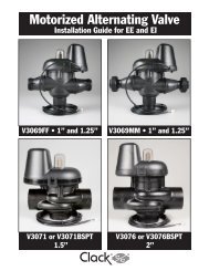
Motorized Alternating Valves (MAV) with these selections. <strong>Clack</strong> No Hard Water Bypass Valves (1” or 1.25” V3070FF or V3070FM) are not<br />
designed to be used with the alternator or separate source functions. The V3063 and V3063BSPT motorized alternating valves are not designed<br />
to be used as a no hard water bypass or separate source inlet if the pressure differential is more than 60 psi.<br />
Confi guring the Control Valve for No Hard Water Bypass Operation:<br />
Select nHbP for control operation. For no hard water bypass operation the three wire connector is not<br />
used.<br />
Selection requires that a connection to MAV or a <strong>Clack</strong> No Hard Water Bypass Valve is made to the two<br />
pin connector labeled ALTERNATOR DRIVE located on the printed circuit board. If using a MAV, the<br />
A port of the MAV must be plugged and the valve outlet connected to the B port. When set to nHbP<br />
the MAV will be driven closed before the fi rst regeneration cycle that is not FILL or SOFTENING or<br />
FILTERING, and be driven open after the last regeneration cycle that is not FILL.<br />
NOTE: If the control valve enters into an error state during regeneration mode, the no hard water bypass<br />
valve will remain in its current state until the error is corrected and reset.<br />
Confi guring the Control Valve for Separate Source Operation:<br />
Select SEPS for control operation. For separate source operation the three wire connector is not used.<br />
Selection requires that a connection to a <strong>Clack</strong> Motorized Alternator Valve (MAV) is made to the two<br />
pin connector labeled ALTERNATOR DRIVE located on the printed circuit board. The C port of the<br />
MAV must be connected to the valve inlet and the A port connected to the separate source used during<br />
regeneration. The B port must be connected to the feed water supply.<br />
When set to SEPS the MAV will be driven closed before the fi rst regeneration cycle, and be driven open<br />
after the last regeneration cycle.<br />
NOTE: If the control valve enters into an error state during regeneration mode, the MAV will remain in its<br />
current state until the error is corrected and reset.<br />
Selecting the Control Valve to act as an alternator:<br />
618.3 and higher = Use 3-wire Interconnect Cables for all communication between units.<br />
616.6 and lower = Use 2-wire Interconnect Cables for twin alternators with independent fl ow meters.<br />
Prior to starting the <strong>programming</strong> steps, connect the interconnect cable to each control valve board’s three pin connector labeled<br />
“INTERCONNECT”. Also connect the meter cord to either control valve to the three pin connector labeled “METER”.<br />
Valve Programming Steps<br />
Confi guration<br />
Settings<br />
Step 4CS Select Volume Set Volume<br />
Confi guration<br />
Settings<br />
Step 5CS Set regeneration time option to “On O”. Set regeneration time option to “On O”.<br />
Confi guration<br />
Settings<br />
Installer Display<br />
Setting<br />
Installer Display<br />
Setting<br />
Step 6CS<br />
Set to ALTA<br />
Connect ALTA valve to the MAV’s A<br />
port and connect the MAV’s two pin wire<br />
connector to the two pin connector labeled<br />
“DRIVE” on the ALTA valve<br />
Step 2I Enter the Volumetric Capacity for the System<br />
Set to ALTb<br />
Connect ALTb valve to the MAV’s B port. No<br />
connections between the ALTB valve and the MAV<br />
are made.<br />
Enter the Volumetric Capacity for the System (the<br />
same as Valve A)<br />
Step 3I Set Day Over ride to “oFF” Set Day Over ride to “oFF”<br />
NOTE: If the control valve is in an error state during regeneration mode the MAV will close the B port and keep open the A port until the error is<br />
corrected and reset.