Clack EI programming manual - Dime WATER
Clack EI programming manual - Dime WATER
Clack EI programming manual - Dime WATER

You also want an ePaper? Increase the reach of your titles
YUMPU automatically turns print PDFs into web optimized ePapers that Google loves.
Page 10 <strong>EI</strong> Man u al<br />
Confi guring the Control Valve for System Controller Operation:<br />
Select “SYS” to link control valve to System Controller. For communication between control valve and<br />
System Controller, a three-wire communication cable is required.<br />
Selection requires that a connection to a <strong>Clack</strong> No Hard Water Bypass (V3070FF or V3070FM) be made<br />
to the two-pin connector labeled ALTERNATOR DRIVE located on the printed circuit board for WS1<br />
and WS1.25 control valves. For valve types “38” for 1.5” (38mm), “50L” for 2”L (50mm), and “50” for<br />
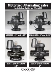
WS2 (50mm), a connection from a <strong>Clack</strong> Motorized Alternating Valve (MAV) (V3071/ BSPT or V3076/<br />
BSPT) to the two pin connector labeled ALTERNATOR DRIVE located on the printed circuit board is<br />
required. NOTE: A pipe plug must be installed in the “A” port of a V3071/ BSPT or V3076/ BSPT to<br />
make it into a No Hard Water Bypass valve.<br />
Press NEXT to go to Step 7CS. Press REGEN to return to previous step.<br />
Step 7CS<br />
EXIT TO<br />
DISPLAY<br />
SCREENS<br />
Step 7CS – Selecting the use of an outside signal<br />
to initiate a regeneration: Selection only matters if a<br />
connection is made to the two pin connector labeled DP<br />
SWITCH located on the printed circuit board. Following<br />
is an explanation of the options:<br />
oFF - feature not used<br />
NOTE: In a twin alternating system each control must<br />
have a separate dP signal or dP switch. One dP signal<br />
or one dP switch cannot be used for both controls.<br />
on0 – If the dP switch is closed for an accumulative time<br />
of 2 minutes a regeneration will be<br />
signaled to the unit. In a twin alternating system the MAV<br />
will transition fi rst to switch units so that<br />
the signaled unit can start regeneration. After the<br />
MAV has fully transitioned, the regeneration begins<br />
immediately. Note: For WS1 – WS2L control valves<br />
programmed for twin alternating: if the dP function “on0”<br />
is set, the Delayed Rinse and Fill feature is not available.<br />
dELy – If the dP switch is closed for an accumulative<br />
time of 2 minutes a regeneration will occur at the<br />
scheduled delayed regeneration time. In a twin alternating<br />
system once the dP switch is triggered the PC Board will<br />
display “REGEN TODAY” and when the delayed regen<br />
time comes the control will switch tanks and the triggered<br />
unit will then go into regeneration. Note: For WS1 –<br />
WS2L control valves programmed for twin alternating: if<br />
the dP function “dEL” is set, the Delayed Rinse and Fill<br />
feature is not available.<br />
HoLd – If the dP switch is closed a regeneration will be<br />
prevented from occurring while there is switch closure.<br />
In a twin alternating system the regeneration of a unit<br />
can be prevented upon switch closure. If the unit depletes<br />
the capacity down to zero, it will not be allowed to<br />
switch tanks to regenerate until the switch is open. Note:<br />
For WS1 – WS2L control valves programmed for twin<br />
alternating the Delayed Rinse and Fill feature can be set<br />
in conjunction with the “HoLd” if desired.<br />
Press NEXT to exit Confi guration Settings. Press REGEN<br />
to return to previous step.