Clack EI programming manual - Dime WATER
Clack EI programming manual - Dime WATER
Clack EI programming manual - Dime WATER

Create successful ePaper yourself
Turn your PDF publications into a flip-book with our unique Google optimized e-Paper software.
Water Specialist <strong>EI</strong><br />
Control Valve<br />
Programming and Cover Drawing Manual
Page 2 <strong>EI</strong> Man u al
<strong>EI</strong> Man u al Page 3<br />
Table of Contents<br />
<strong>EI</strong> Front Cover and Drive Assembly ................................................................................................................................... 4<br />
Regeneration and Error Screens .......................................................................................................................................... 5<br />
User Displays ...................................................................................................................................................................... 6<br />
Confi guration Settings ........................................................................................................................................................ 7<br />
Setting Regeneration Cycle Times .................................................................................................................................... 11<br />
Installer Display Settings .................................................................................................................................................. 12<br />
Diagnostics ........................................................................................................................................................................ 14
Page 4 <strong>EI</strong> Man u al<br />
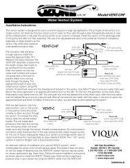
<strong>EI</strong> Front Cover and Drive Assembly<br />
Drawing No. Order No. Description Quantity<br />
1 V3175<strong>EI</strong>-01 WS1<strong>EI</strong> FRONT COVER ASSEMBLY 1<br />
2 V3107-01 WS1 MOTOR 1<br />
3 V3106-01 WS1 DRIVE BRACKET & SPRING CLIP 1<br />
4 V3408<strong>EI</strong>-03BOARD WS1THRU2L/2 <strong>EI</strong> PCBRD MAV/ALT REPL 1<br />
5 V3110 WS1 DRIVE REDUCING GEAR 12X36 3<br />
6 V3109 WS1 DRIVE GEAR COVER 1<br />
V3186 WS1 AC ADAPTER 110V-12V<br />
Not Shown<br />
V3186EU<br />
V3186UK<br />
WS1 AC ADAPTER 220-240V-12V EU<br />
WS1 AC ADAPTER 220-240V-12V UK<br />
1<br />
V3186-01 WS1 AC ADAPTER CORD ONLY<br />
Not Shown V3178 WS1 Drive Back Plate 1<br />
Refer to Control Valve Service Manual for other drawings and part numbers.<br />
When replacing the battery, align<br />
positives and push down to fully seat.<br />
Battery Fully Seated<br />
1<br />
AC Adapter U.S. International<br />
Supply Voltage 120 V AC 230V AC<br />
Supply Frequency 60 Hz 50 Hz<br />
Output Voltage 12 V AC 12 V AC<br />
Output Current 500 mA 500 mA<br />
Correct<br />
Battery<br />
Orientation<br />
2<br />
Battery replacement is<br />
3 volt lithium coin cell<br />
type 2032.<br />
4<br />
5<br />
6<br />
3
<strong>EI</strong> Man u al Page 5<br />
Scrolls to the next display.<br />
Regeneration and Error Screens<br />
Regen Screen<br />
Displays the time remaining in the current cycle. Pressing REGEN advances to the next cycle.<br />
Error Screen<br />
Alternated fl ashing Err and error code every 3 seconds. Clear by dissconnecting<br />
the power supply at the PC board and reconneting, or press NEXT and REGEN<br />
simutaneously for 3 seconds.<br />
In Alternator Systems when a unit is waiting to initiate the fi rst cycle step of regeneration,<br />
“REGEN PndG” is displayed.<br />
“STbY” is displayed in Alternator Systems when a valve is in Standby state.<br />
“REGEN PndG RINSE FILL” is displayed whenever a zero-capacity tank has transferred to<br />
an off-line state and is currently waiting to initiate the second portion of a regeneration cycle.<br />
Viewed only when Delayed Rinse and Fill is set to ON.<br />
Button Operation and Function<br />
Pressing once and releasing will schedule a regeneration at the preset delayed regeneration time.<br />
Pressing again and releasing will cancel the regeneration.<br />
Pressing and holding for 3 seconds will initiate an immediate regeneration<br />
Pressing while in regeneration will advance to the next cycle.<br />
Pressing in the program levels will go backwards to the previous screen<br />
Changes variable being displayed.<br />
Key sequence to lock and unlock program settings.<br />
Holding for 3 seconds initiates a control reset.The software version is displayed and the piston returns<br />
to the home/service position, resynchronizing the valve.<br />
Regeneration Cycles and Times<br />
Cycle Range of times (min.)<br />
1. Backwash 1 st (upfl ow)<br />
2. Regenerant Draw/Slow Rinse (downfl ow)<br />
3. Backwash 2 nd (upfl ow)<br />
4. Fast Rinse (downfl ow)<br />
5. Regenerant Refi ll (with treated water)<br />
6. Service (downfl ow)<br />
1 - 95 or OFF<br />
1 - 180 or OFF<br />
1 - 95 or OFF<br />
1 - 95 or OFF<br />
0.1 - 99.9 or OFF<br />
The user can initiate <strong>manual</strong> regeneration. The user has the option to request the <strong>manual</strong> regeneration at the delayed regeneration<br />
time or to have the regeneration occur immediately:<br />
1. Pressing and releasing the REGEN button. “ ” will fl ash towards Regen on the display and the regeneration will occur at the<br />
delayed regeneration time. The user can cancel the request by pressing and releasing the REGEN button.<br />
2. Pressing and holding the REGEN button for approximately 3 seconds will immediately start the regeneration. The user cannot<br />
cancel this request, except by resetting the control by pressing NEXT and REGEN simultaneously for 3 seconds.
Page 6 <strong>EI</strong> Man u al<br />
User Displays<br />
General Operation When the system is operating, one of fi ve displays may be shown.<br />
Pressing NEXT will alternate between the displays shown below.<br />
User 1<br />
Typical user display. If volume is selected in Confi guration Settings<br />
Step 4CS, shows volume remaining to regeneration. If volume is not<br />
selected in Confi guration Settings Step 4CS, this screen will not be<br />
shown. If a meter is not used this display will not change.<br />
User 2<br />
Displays number of days to next regeneration.<br />
User 3<br />
Displays fl ow rate M 3 /Hour. If a meter is not used this display will<br />
be shown but 0 will be displayed.<br />
User 4<br />
Displays total fl ow in cubic meters since last reset. If a meter is not<br />
used this display will be shown but 0 will be displayed.<br />
PRESS ▼ FOR 3 SECONDS TO RESET TO 0.<br />
User 5<br />
Shows current time.<br />
Setting Time of Day<br />
Push NEXT until time of day screen is displayed. Press and hold ▲<br />
or ▼ until the SET indicator is displayed and the hour fl ashes. Press<br />
▲ or ▼ until the correct hour is displayed.<br />
Then press NEXT. The minutes will fl ash. Press ▲ or ▼ until the<br />
correct minute is displayed.<br />
Press NEXT to return to the Display Screens. Time of day should<br />
only need to be set after power outages lasting more than 8 hours,<br />
if the battery has been depleted and a power outage occurs, or when<br />
daylight saving time begins or ends. If a power outage lasting more<br />
than 8 hours occurs, the time of day will fl ash on and off which<br />
indicates the time of day should be reset. If a power outage lasts less<br />
than 8 hours and the time of day fl ashes on and off, the time of day<br />
should be reset and the battery replaced.
<strong>EI</strong> Man u al Page 7<br />
Step 1CS<br />
Step 2CS<br />
Step 3CS<br />
Step 4CS<br />
Step 5CS<br />
Confi guration Settings<br />
Step 1CS – Press ▲ and ▼ simultaneously for 5 seconds and release. If screen in Step 2CS does not<br />
appear, the lock on the valve is activated. To unlock press ▼, NEXT, REGEN, ▲ in sequence, then press ▲<br />
and ▼ simultaneously for 5 seconds and release.<br />
Step 2CS – Select 25 for 1” (25 mm), 32 for 1.25” (32 mm), 38 for 1.5” (38 mm), 50L for 2L (50mm) or 50<br />
for 2” (50mm) valve ¹. Press NEXT to go to Step 3CS. Press REGEN to exit Confi guration Settings.<br />
Note: When using the WS2 valve, if 50L is set instead of 50, when the valve is in regeneration and the<br />
piston drives to the DRAW cycle the piston will stall and generate a 1002 error code. Clear the error code<br />
by pressing NEXT and REGEN simultaneously until the valve resets, then re-program valve to proper<br />
valve type setting.<br />
Step 3CS – When 50L or 50 is selected, an additional screen will appear. It is used to select which size fl ow<br />
meter is to be used with the valve, 1.5” (38) or 2.0” (50).<br />
Press NEXT to go to Step 4CS. Press REGEN to return to previous step.<br />
Step 4CS – Press ▲ or ▼ to select one of the following:<br />
• If Volume (M 3 ) is selected the regeneration will occur after the specifi c volume has been used or on the<br />
day override (if selected) whichever comes fi rst.<br />
• If 28 is selected the regeneration will occur on the day (1 through 28) selected in Installer Display<br />
Settings. The total fl ow and fl ow rate user displays and the volume display in Diagnostics will not be<br />
shown even if a meter is used.<br />
• If 28/Volume (M 3 ) is selected the regeneration will occur on the day (1 through 28) selected in Installer<br />
Display Settings. If a meter is not used the total fl ow and fl ow rate user displays and the volume display in<br />
Diagnostics will be shown as 0.<br />
• If 7 is selected the regeneration will occur on the selected day(s) of the week (see instructions contained<br />
in Installer Display Settings). The total fl ow and fl ow rate user displays and the volume display in<br />
Diagnostics will not be shown even if a meter is used.<br />
• If 7/Volume (M 3 ) is selected the regeneration will occur on the selected day(s) of the week<br />
(see instructions contained in Installer Display Settings). If a meter is not used the total fl ow and fl ow rate<br />
user displays and the volume display in Diagnostics will be shown as 0.<br />
Press NEXT to go to Step 5CS. Press REGEN to return to previous step.<br />
Step 5CS – Press ▲ or ▼ to select to regenerate immediately on 0 or at delayed time. Immediately on 0<br />
can only be selected if Volume (M 3 ) was selected in step 3CS and a meter must be installed. Delay is the<br />
only option for the other Step 3CS selections. Press NEXT to go to Step 5CS. Press REGEN to return to<br />
previous step.<br />
¹ When using the WS2 control valve, the circuit board software must have meter selection choices of 50 and 50L. The WS2 valve must be set for the 50 meter selection<br />
during <strong>programming</strong>. If the software version does not have both the 50 and 50L selections, consult your equipment supplier for a replacement circuit board. When using<br />
the WS2L valve with older version software that does not have both 50 and 50L selection choices, the valve must be set to 50, if using a 2” meter or 38 if using a 1.5”<br />
meter. If a WS2L valve is being used with newer version software that has both 50 and 50L selection choices, the valve must be set for 50L during <strong>programming</strong>.
Page 8 <strong>EI</strong> Man u al<br />
Step 6CS<br />
Step 6CS – Allows selection of one of the following<br />
using ▲ or ▼:<br />
• the Control Valve to have no hard water bypass;<br />
• the Control Valve to act as an alternator;<br />
• the Control Valve to have a separate source during the<br />
regeneration cycle; or<br />
• the Control Valve to operate with the System Controller.<br />
Select OFF when none of these features are used.<br />
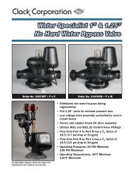
Only use <strong>Clack</strong> No Hard Water Bypass Valves or <strong>Clack</strong><br />
Motorized Alternating Valves (MAV) with these selections. <strong>Clack</strong> No Hard Water Bypass Valves (1” or 1.25” V3070FF or V3070FM) are not<br />
designed to be used with the alternator or separate source functions. The V3063 and V3063BSPT motorized alternating valves are not designed<br />
to be used as a no hard water bypass or separate source inlet if the pressure differential is more than 60 psi.<br />
Confi guring the Control Valve for No Hard Water Bypass Operation:<br />
Select nHbP for control operation. For no hard water bypass operation the three wire connector is not<br />
used.<br />
Selection requires that a connection to MAV or a <strong>Clack</strong> No Hard Water Bypass Valve is made to the two<br />
pin connector labeled ALTERNATOR DRIVE located on the printed circuit board. If using a MAV, the<br />
A port of the MAV must be plugged and the valve outlet connected to the B port. When set to nHbP<br />
the MAV will be driven closed before the fi rst regeneration cycle that is not FILL or SOFTENING or<br />
FILTERING, and be driven open after the last regeneration cycle that is not FILL.<br />
NOTE: If the control valve enters into an error state during regeneration mode, the no hard water bypass<br />
valve will remain in its current state until the error is corrected and reset.<br />
Confi guring the Control Valve for Separate Source Operation:<br />
Select SEPS for control operation. For separate source operation the three wire connector is not used.<br />
Selection requires that a connection to a <strong>Clack</strong> Motorized Alternator Valve (MAV) is made to the two<br />
pin connector labeled ALTERNATOR DRIVE located on the printed circuit board. The C port of the<br />
MAV must be connected to the valve inlet and the A port connected to the separate source used during<br />
regeneration. The B port must be connected to the feed water supply.<br />
When set to SEPS the MAV will be driven closed before the fi rst regeneration cycle, and be driven open<br />
after the last regeneration cycle.<br />
NOTE: If the control valve enters into an error state during regeneration mode, the MAV will remain in its<br />
current state until the error is corrected and reset.<br />
Selecting the Control Valve to act as an alternator:<br />
618.3 and higher = Use 3-wire Interconnect Cables for all communication between units.<br />
616.6 and lower = Use 2-wire Interconnect Cables for twin alternators with independent fl ow meters.<br />
Prior to starting the <strong>programming</strong> steps, connect the interconnect cable to each control valve board’s three pin connector labeled<br />
“INTERCONNECT”. Also connect the meter cord to either control valve to the three pin connector labeled “METER”.<br />
Valve Programming Steps<br />
Confi guration<br />
Settings<br />
Step 4CS Select Volume Set Volume<br />
Confi guration<br />
Settings<br />
Step 5CS Set regeneration time option to “On O”. Set regeneration time option to “On O”.<br />
Confi guration<br />
Settings<br />
Installer Display<br />
Setting<br />
Installer Display<br />
Setting<br />
Step 6CS<br />
Set to ALTA<br />
Connect ALTA valve to the MAV’s A<br />
port and connect the MAV’s two pin wire<br />
connector to the two pin connector labeled<br />
“DRIVE” on the ALTA valve<br />
Step 2I Enter the Volumetric Capacity for the System<br />
Set to ALTb<br />
Connect ALTb valve to the MAV’s B port. No<br />
connections between the ALTB valve and the MAV<br />
are made.<br />
Enter the Volumetric Capacity for the System (the<br />
same as Valve A)<br />
Step 3I Set Day Over ride to “oFF” Set Day Over ride to “oFF”<br />
NOTE: If the control valve is in an error state during regeneration mode the MAV will close the B port and keep open the A port until the error is<br />
corrected and reset.
<strong>EI</strong> Man u al Page 9<br />
Retracted<br />
Valve “A” in Service Position =<br />
MAV piston rod Retracted<br />
Extended<br />
Valve “B” in Service Position = MAV<br />
piston rod Extended<br />
NOTE: <strong>Clack</strong> twin alternators can be set up to operate with a day over-ride setting in conjunction with the main volume based regeneration<br />
setting. If a system is programmed for twin alternating with a delayed regeneration, a <strong>Clack</strong> twin alternator can perform an immediate transfer<br />
of the MAV to place a fully regenerated tank on-line and have a delayed regeneration time for the exhausted unit. <strong>Clack</strong> twin alternators will<br />
only count days on the unit that is on-line which will allow the twin alternating system to regenerate based on only a day over-ride setting when<br />
programmed to regenerate based on days.<br />
For <strong>Clack</strong> Corporation alternator systems using WS1, WS1.25, WS1.5, and WS2L valves<br />
there will be an option to delay the last two cycles of regeneration (only “Rinse” and “Fill”).<br />
This feature splits the regeneration into two portions. The fi rst portion of the regeneration<br />
will start immediately and all programmed cycles before the “Rinse” and “Fill” cycles will be<br />
performed. After all programmed cycles before “Rinse” and “Fill” are completed the control<br />
valve will drive to the service position (displaying “Delayed Rinse + Fill Pending”). When<br />
the volume of the on-line unit is depleted to 10% of its programmed capacity, the control<br />
valve will be triggered to fi nish the second portion of the regeneration and complete the<br />
“Rinse” and “Fill” cycles and return to Service and be placed into Standby mode, and wait to<br />
come on-line for service.<br />
For <strong>Clack</strong> Corporation alternator systems using the WS2 valve, when NEXT is pressed after<br />
selecting ALTA or ALTB, a display will allow the user to set the amount of pre-service rinse<br />
time for the stand by tank just prior to returning to service.<br />
WS1, WS1.25, WS1.5,<br />
WS2L Valves<br />
WS2 Valve
Page 10 <strong>EI</strong> Man u al<br />
Confi guring the Control Valve for System Controller Operation:<br />
Select “SYS” to link control valve to System Controller. For communication between control valve and<br />
System Controller, a three-wire communication cable is required.<br />
Selection requires that a connection to a <strong>Clack</strong> No Hard Water Bypass (V3070FF or V3070FM) be made<br />
to the two-pin connector labeled ALTERNATOR DRIVE located on the printed circuit board for WS1<br />
and WS1.25 control valves. For valve types “38” for 1.5” (38mm), “50L” for 2”L (50mm), and “50” for<br />
WS2 (50mm), a connection from a <strong>Clack</strong> Motorized Alternating Valve (MAV) (V3071/ BSPT or V3076/<br />
BSPT) to the two pin connector labeled ALTERNATOR DRIVE located on the printed circuit board is<br />
required. NOTE: A pipe plug must be installed in the “A” port of a V3071/ BSPT or V3076/ BSPT to<br />
make it into a No Hard Water Bypass valve.<br />
Press NEXT to go to Step 7CS. Press REGEN to return to previous step.<br />
Step 7CS<br />
EXIT TO<br />
DISPLAY<br />
SCREENS<br />
Step 7CS – Selecting the use of an outside signal<br />
to initiate a regeneration: Selection only matters if a<br />
connection is made to the two pin connector labeled DP<br />
SWITCH located on the printed circuit board. Following<br />
is an explanation of the options:<br />
oFF - feature not used<br />
NOTE: In a twin alternating system each control must<br />
have a separate dP signal or dP switch. One dP signal<br />
or one dP switch cannot be used for both controls.<br />
on0 – If the dP switch is closed for an accumulative time<br />
of 2 minutes a regeneration will be<br />
signaled to the unit. In a twin alternating system the MAV<br />
will transition fi rst to switch units so that<br />
the signaled unit can start regeneration. After the<br />
MAV has fully transitioned, the regeneration begins<br />
immediately. Note: For WS1 – WS2L control valves<br />
programmed for twin alternating: if the dP function “on0”<br />
is set, the Delayed Rinse and Fill feature is not available.<br />
dELy – If the dP switch is closed for an accumulative<br />
time of 2 minutes a regeneration will occur at the<br />
scheduled delayed regeneration time. In a twin alternating<br />
system once the dP switch is triggered the PC Board will<br />
display “REGEN TODAY” and when the delayed regen<br />
time comes the control will switch tanks and the triggered<br />
unit will then go into regeneration. Note: For WS1 –<br />
WS2L control valves programmed for twin alternating: if<br />
the dP function “dEL” is set, the Delayed Rinse and Fill<br />
feature is not available.<br />
HoLd – If the dP switch is closed a regeneration will be<br />
prevented from occurring while there is switch closure.<br />
In a twin alternating system the regeneration of a unit<br />
can be prevented upon switch closure. If the unit depletes<br />
the capacity down to zero, it will not be allowed to<br />
switch tanks to regenerate until the switch is open. Note:<br />
For WS1 – WS2L control valves programmed for twin<br />
alternating the Delayed Rinse and Fill feature can be set<br />
in conjunction with the “HoLd” if desired.<br />
Press NEXT to exit Confi guration Settings. Press REGEN<br />
to return to previous step.
<strong>EI</strong> Man u al Page 11<br />
Remaining M3 /Hour Time M 3<br />
Set<br />
Total<br />
X1000<br />
Regen<br />
EXIT TO<br />
DISPLAY<br />
SCREENS<br />
Step 1CT<br />
Step 2CT<br />
Days<br />
Step 3CT<br />
Step 4CT<br />
Step 5CT<br />
Step 6CT<br />
Step 7CT<br />
Backwash<br />
Draw<br />
Rinse<br />
Fill<br />
Setting Regeneration Cycle Times<br />
Step 1CT - Press NEXT and ▼ simultaneously for 5 seconds and release. If<br />
screen in Step 2CT does not appear, the lock on the valve is activated. To unlock<br />
press ▼, NEXT, REGEN, ▲ in sequence, then press NEXT and ▼ simultaneously<br />
for 5 seconds and release.<br />
Step 2CT - Select between SOFTENING or FILTERING.<br />
When set to FLTr, 7CT is not set to oFF, and 2CS is set to 25, a fi xed 30-second<br />
Backwash is automatically added to the regen cycle program after Rinse 6CT.<br />
The status display for this extra backwash will appear as just another cycle step in<br />
sequence.<br />
Press NEXT to go to Step 3CT. Press REGEN to exit Regeneration Cycle Times.<br />
Step 3CT - Adjust the length of the backwash from 1-95 minutes or OFF using<br />
▲ or ▼.<br />
Press NEXT to go to Step 4CT. Press REGEN to return to previous step.<br />
Step 4CT - Adjust the length of the regenerant draw from 1-180 minutes or OFF<br />
using ▲ or ▼.<br />
Press NEXT to go to Step 5CT. Press REGEN to return to previous step.<br />
Step 5CT - Adjust the length of the second backwash from 1-95 minutes or OFF<br />
using ▲ or ▼.<br />
Press NEXT to go to Step 6CT. Press REGEN to return to previous step.<br />
Step 6CT - Adjust the length of rinse from 1-95 minutes or OFF using ▲ or ▼.<br />
Press NEXT to go to Step 7CT. Press REGEN to return to previous step.<br />
Step 7CT - Adjust the length of fi ll from 0.1-99.0 minutes or OFF. WS2 valves<br />
are shipped from the factory with a refi ll fl ow control of 2.2 gpm (8.3 lpm). All<br />
other control valves are shipped from the factory with a refi ll fl ow control of 0.5<br />
gpm (1.9 lpm).<br />
Press NEXT to exit Regeneration Cycle Times. Press REGEN to return to previous<br />
step.
Page 12 <strong>EI</strong> Man u al<br />
Installer Display Settings<br />
One of three sets of displays will be shown depending on what was selected in Confi guration Settings Step 4CS.<br />
EXIT TO<br />
DISPLAY<br />
SCREENS<br />
EXIT TO<br />
DISPLAY<br />
SCREENS<br />
Volume (M 3 ) selected in Confi guration Settings Step 4CS<br />
Step 1I<br />
Step 2I<br />
Step 3I<br />
Step 4I<br />
Step 5I<br />
Step 1I - To enter Installer Display press NEXT and ▲<br />
simultaneously for 5 seconds and release.<br />
Step 2I - Volumetric capacity in cubic meters to<br />
regeneration. Press NEXT to go to Step 3I. Press REGEN<br />
to exit Installer Display.<br />
Step 3I - Adjust day override from 1 - 28 or OFF.<br />
Press NEXT to go to Step 4I. Press REGEN to return to<br />
previous step.<br />
Step 4I - Use ▲ or ▼ to set the regen hour.<br />
Press NEXT to go to Step 5I. Press REGEN to return to<br />
the previous step.<br />
28 Day or 28/Volume (M3 ) selected in Confi guration Settings Step 4CS<br />
Step 1I<br />
Step 1I - To enter Installer Display press the NEXT and<br />
▲ simultaneously for fi ve seconds and release.<br />
Step 2I<br />
Step 3I<br />
Step 4I<br />
Step 5I - Use ▲ or ▼ to set the regen minutes. Press<br />
NEXT to exit Installer Display. Press REGEN to return to<br />
previous step.<br />
Step 2I - Adjust days from 1 - 28. Press NEXT to go to<br />
Step 3I. Press REGEN to exit Installer Display.<br />
Step 3I - Use ▲ or ▼ to set time of the regen hour. Press<br />
NEXT to go to Step 4I. Press REGEN to return to previous<br />
step.<br />
Step 4I - Use ▲ and ▼ to set the regen minutes. Press<br />
NEXT to exit Installer Display. Press REGEN to return to<br />
previous step.
<strong>EI</strong> Man u al Page 13<br />
EXIT TO<br />
DISPLAY<br />
SCREENS<br />
7 Day or 7/Volume (M 3 ) selected in Confi guration Settings Step 4CS<br />
Step 1I<br />
Step 2I<br />
Step 3I<br />
Step 4I<br />
Step 5I<br />
Step 1I - To enter Installer Display press NEXT and ▲<br />
simultaneously for 5 seconds and release.<br />
Step 2I - Use ▲ or ▼ to set the current day of the week.<br />
Default = 2 (Monday)<br />
1 = SUNDAY<br />
2 = MONDAY<br />
3 = TUESDAY<br />
4 = WEDNESDAY<br />
5 = THURSDAY<br />
6 = FRIDAY<br />
7 = SATURDAY<br />
Press NEXT to go to Step 3I. Press REGEN to exit<br />
Installer Display.<br />
Step 3I - Scroll through days 1 to 7 using NEXT. Use<br />
▲ or ▼ to turn regen on or off for each individual day<br />
(regen indicator on means regeneration will happen).<br />
After completing the 7th day, press NEXT to go to Step<br />
4I. Press REGEN to go to previous display.<br />
Step 4I - Use ▲ or ▼ to set the regen hour.<br />
Press NEXT to go to Step 5I. Press REGEN<br />
to go to previous display.<br />
Step 5I - Use ▲ or ▼ to set the regen<br />
minutes. Press NEXT to exit Installer Display.<br />
Press REGEN to return to previous display.
Page 14 <strong>EI</strong> Man u al<br />
EXIT TO<br />
DISPLAY<br />
SCREENS<br />
Step 1D<br />
Step 2D<br />
Step 3D<br />
Step 4D<br />
Step 5D<br />
Diagnostics<br />
Step 1D - Press ▲ and ▼ simultaneously for 5 seconds<br />
and release. Then press ▲ and ▼ simultaneously for<br />
3 seconds and release. If screen in Step 2D does not<br />
appear the lock on the valve is activated. To unlock press<br />
▼, NEXT, REGEN, ▲ in sequence, then press ▲ and ▼<br />
simultaneously for 5 seconds and release. Then press<br />
▲ and ▼ simultaneously for 3 seconds and release.<br />
Step 2D - Display shows the number of days since a<br />
regeneration last occurred. Press NEXT to go to Step<br />
3D. Press REGEN to exit Diagnostics.<br />
Step 3D - Display shows the volume of water treated in<br />
M 3 treated since the last regeneration. If Volume (M 3 ),<br />
28/Volume (M 3 ), or 7/Volume (M 3 ) was selected in Step<br />
3CS and no meter is installed this display will read 0.<br />
Press NEXT to go to Step 4D. Press REGEN to return to<br />
previous step.<br />
Step 4D - Display shows the days in service since start<br />
up. Press NEXT to go to Step 5D. Press REGEN to<br />
return to previous step.<br />
Step 5D - Display shows the total number of<br />
regeneration cycles since start up. Press NEXT to exit<br />
Diagnostics. Press REGEN to return to previous step.
<strong>EI</strong> Man u al Page 15<br />
Revision History:<br />
6/27/2011<br />
PAGE 4:<br />
V3408<strong>EI</strong>-03BOARD WS1THRU2L/2 <strong>EI</strong> PCBRD 1<br />
PAGE 5:<br />
Added additional regeneration screens<br />
Regeneration Cycles and Times<br />
Cycle Range of times (min.)<br />
1. Backwash 1 st (upfl ow)<br />
2. Regenerant Draw/Slow Rinse (downfl ow)<br />
3. Backwash 2 nd (upfl ow)<br />
4. Fast Rinse (downfl ow)<br />
5. Regenerant Refi ll (with treated water)<br />
6. Service (downfl ow)<br />
PAGE 7:<br />
Added Step 3CS, changed old Step 3CS to 4CS.<br />
Added screen displays for Regeneration Type selections.<br />
PAGE 8:<br />
Added display screens for No Hard Water Bypass and Separate Source.<br />
PAGE 9:<br />
Added MAV information<br />
PAGE 10:<br />
Added System Controller information<br />
Revised Step 7CS<br />
PAGE 11:<br />
Updated cycle time ranges<br />
1 - 95 or OFF<br />
1 - 180 or OFF<br />
1 - 95 or OFF<br />
1 - 95 or OFF<br />
0.1 - 99.9 or OFF
Page 16 <strong>EI</strong> Man u al<br />
Form No. V3435<strong>EI</strong> – 7/7/2011