Alternating valves Guide - ClackValves.Net
Alternating valves Guide - ClackValves.Net
Alternating valves Guide - ClackValves.Net

You also want an ePaper? Increase the reach of your titles
YUMPU automatically turns print PDFs into web optimized ePapers that Google loves.
Order No. V3069FF • Description: MOTOR ALT VLV 1/125 F-F<br />
or<br />
Order No. V3069MM • Description: MOTOR ALT VLV 1/125 M-M<br />
Clack Item Number Software Minimum Rev Level Before using V3069FF or V3069MM with<br />
V3408EE-01BOARD 513.7<br />
V3408EI-01BOARD 613.5<br />
V3108CI-02BOARD 316.9<br />
Plan the position of the motorized alternator valve and control <strong>valves</strong> (each with their own meter) carefully because of the following:<br />
• The 8’ alternator valve motor cable (V3476) must be threaded through the back plate and connected to the two pin connector labeled DRIVE on the ALT A<br />
control valve board. Approximately 1’ of the cable length should be allowed for weaving through the back plate.<br />
• The 8’ interconnect cable (V3474-01) must be threaded through the back plates and connected to the three pin connector labeled INTERCONNECT<br />
CABLE on both the ALT A and ALT b control <strong>valves</strong>. Approximately 2’ of the cable length (1’ for each control valve) should be allowed for weaving through<br />
the back plate. NOTE: Although the interconnect cable V3474-01 has two wires, it must be connected to the three pin connector.<br />
• The 15’ AC Adapter or power cable must be thread through the back plate of both the ALT A and ALT b control <strong>valves</strong>. Approximately 1’ of the cable length<br />
should be allowed for weaving through the back plate. The AC adapter should be installed to a properly grounded, not switched, outlet.<br />
Try to allow suffi cient slack in cables so cables may be zip tied to plumbing lines to prevent the cables from being accidentally pulled. Where necessary, break<br />
out the tab in the back plate to allow two cables to be woven through the same slot in the back plate. No more than two cables may be woven through one<br />
back plate slot. To help prevent damage to cables, allow solder joints to cool or solvent cement joints to cure after completing the various service, drain and<br />
regenerant plumbing connections. Thread the various cables through the appropriate back plate(s) and connect as described in the bullets above.<br />
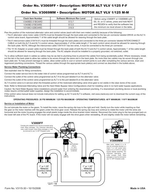
Service Water Plumbing Connections<br />
See exploded view for fi tting connections.<br />
Connect the water service line to the water inlet of control <strong>valves</strong> programmed as ALT A and ALT b.<br />
Connect the outlet of the control valve programmed as ALT A to the port labeled A on the alternator valve.<br />
Connect the outlet of the control valve programmed as ALT b to the port labeled B on the alternator valve.<br />
ALT A control valve is in service when the threaded portion of the motorized alternating valve drive gear is not visible in the clear dome of the cover.<br />
Note: Refer to Motorized <strong>Alternating</strong> Valve and No Hard Water Bypass Valve Confi gurations chart for installing valve in no hard water bypass applications.<br />
Caution: No Hard Water Bypass Valve installations prevent water from entering the downstream plumbing. If a downstream plumbing device or local plumbing<br />
codes require uninterrupted water supplies, design the installation to accommodate.<br />
If the control valve manual does not include instructions for setting up ALT A and ALT b software, visit www.clackcorp.com to download the current copy of the<br />
instructions.<br />
OPERATING PRESSURES: 20 PSI MINIMUM / 125 PSI MAXIMUM • OPERATING TEMPERATURES: 40°F MINIMUM / 110°F MAXIMUM<br />
Service or Installation of Motor<br />
Do not lubricate the motor or the gears. To install the motor, move the spring clip loop to the right and hold. Gently turn the motor while inserting so that<br />
the gear on the motor meshes with the gears under the drive gear cover. Release the spring clip loop and continue to rotate the motor until the wires are<br />
horizontal and the motor housing engages the small plastic bulge inside the drive bracket motor retainer. Reconnect the motor plug to the two-pronged jack on<br />
the lower left side of the PC board. If the motor will not easily engage with the drive gears when reinstalling, lift and slightly rotate the motor before reinserting.<br />
V3069FF<br />
Female ports, labeled A or B, may be connected using<br />
Clack fi tting packages. The motorized alternating<br />
valve outlet accepts Clack fi tting packages or may<br />
be removed to use 1½ NPT threaded outlet.<br />
1" or 1.25"<br />
Metered<br />
Control Valve<br />
ALTA<br />
Untreated<br />
water in<br />
A B<br />
Treated<br />
water out<br />
See exploded<br />
view if<br />
1½” NPT<br />
connection<br />
is desired<br />
1" or 1.25"<br />
Metered<br />
Control Valve<br />
ALTb<br />
EE, EI, or CI <strong>valves</strong>, press and hold NEXT<br />
and REGEN to verify that the software has<br />
the minimum rev level shown in the table.<br />
V3069MM<br />
Male ports, labeled A or B,<br />
may be connected directly to a<br />
Clack 1” or 1.25” control valve<br />
outlet or to a V3191-01 vertical<br />
bypass adapter assembly. The<br />
motorized alternating valve<br />
outlet accepts Clack fi tting<br />
packages or may be removed to<br />
use 1½” NPT threaded outlet.<br />
Form No. V3115-30 • 10/15/2008 Made in USA<br />
A B
11<br />
Order No. V3069FF • Description: MOTOR ALT VLV 1/125 F-F<br />
or<br />
Order No. V3069MM • Description: MOTOR ALT VLV 1/125 M-M<br />
Drawing No. Order No. Description<br />
Quantity<br />
V3069FF V3069MM<br />
1 V3073 MAV/NOHWBY COVER ASY 1 1<br />
2 V3476 WS MOTOR ASY 8 FT 1 1<br />
3 V3592 SCREW #8-3/4 PHPN T-25 SS 3 3<br />
4 V3262-01 WS1.5&2ALT/2BY REDUCGEARCVRASY 1 1<br />
5 V3110 WS1 DRIVE REDUCING GEAR 12X36 3 3<br />
6 V3264 WS2 BYPASS REDUCTION GEAR AXLE 3 3<br />
7 V3527 SCREW 1/4-20 X 3/4 BHSCS SS 4 4<br />
8 V3072 MAV/NOHWBY 1/125/15 DRIVE ASY 1 1<br />
9 V3506-01 MAV/NOHRD 1/125/15 PISTON 1 1<br />
10 V3074 MAV/NOHWBY 1/125/15 STACK ASY 1 1<br />
11 V3504FF MAV BODY 1/125 ASY F-F 1 N/A<br />
12 V3504MM MAV BODY 1/125 ASY M-M N/A 1<br />
13 V3151 WS1 NUT 1 QC N/A 2<br />
14 V3150 WS1 SPLIT RING N/A 2<br />
15 V3105 O-RING 215 N/A 2<br />
Not Shown V3474-01 WS ALT MAV 1/125 CORD 8FT BLK 1 1<br />
2<br />
4<br />
3<br />
5<br />
6<br />
7<br />
9<br />
10<br />
1<br />
8<br />
Piston Orientation 1<br />
Motorized <strong>Alternating</strong><br />
Valve and No Hard<br />
Water Bypass Valve<br />
Confi gurations.<br />
Female ports, labeled A or<br />
B, may be connected using<br />
Clack fi tting packages. The<br />
motorized alternating valve<br />
outlet accepts Clack fi tting<br />
packages or may be removed<br />
to use 1½ NPT threaded<br />
outlet.<br />
Piston Orientation 2<br />
No Hard Water Bypass<br />
Valve Confi gurations.<br />
1½” NPT<br />
Threads<br />
•Operating Pressures:<br />
20 PSI Minimum / 125 PSI Maximum<br />
•Operating Temperatures:<br />
40°F Minimum / 110°F Maximum<br />
Quick Connect Nut Threads can be cut off to allow access to 1½”<br />
NPT Threads. Deburr and clean edge after cutting.<br />
NOTE: Tefl on tape is required when using the 1½” NPT Threads.<br />
12<br />
13 14 15<br />
Male ports, labeled A or B, may be connected directly to a<br />
Clack 1” or 1.25” control valve outlet or to a V3191-01 vertical<br />
bypass adapter assembly. The motorized alternating valve<br />
outlet accepts Clack fi tting packages or may be removed to<br />
use 1½” NPT threaded outlet.<br />
Form No. V3115-30 • 10/15/2008 Made in USA
Motorized <strong>Alternating</strong> Valve & No Hard Water Bypass Valve Configurations<br />
8/14/07 RJM<br />
Plumbing Connections Piston Orientation<br />
Software Selection<br />
Piston/Valve Position Flow<br />
Port A Port B Port C 1 2 Control Valve 1 Control Valve 2 Up Down<br />
Flows from Port A to Port<br />
C<br />
Flows from Port B to Port<br />
C<br />
To Outlet Use Not Applicable ALTA ALTb<br />
From Control<br />
Valve 2<br />
From Control<br />
Valve 1<br />
Flows from Port A to Port<br />
C<br />
Flows from Port B to Port<br />
C<br />
To Outlet Use Not Applicable ALTb ALTA<br />
From Control<br />
Valve 1<br />
From Control<br />
Valve 2<br />
MAV Operation<br />
Form No. V3115-30 • 10/15/2008 Made in USA<br />
Closed<br />
Open: Flows from Port A<br />
to Port B<br />
To Outlet Plugged Not Applicable Use nHbP<br />
From Control<br />
Valve<br />
Closed<br />
Open: Flows from Port B<br />
to Port C<br />
To Outlet Use Not Applicable nHbP<br />
From Control<br />
Valve<br />
Plugged<br />
Closed<br />
Open: Flows from Port A<br />
to Port C<br />
Not Applicable Use nHbP<br />
From Control<br />
Valve<br />
To Outlet Plugged<br />
Closed<br />
Open: Flows from Port C<br />
to Port B<br />
Use Not Applicable nHbP<br />
From Control<br />
Valve<br />
Plugged To Outlet<br />
No Hard Water Bypass<br />
Operation<br />
•Operating Pressures:<br />
20 PSI Minimum / 125 PSI Maximum<br />
•Operating Temperatures:<br />
40°F Minimum / 110°F Maximum