You also want an ePaper? Increase the reach of your titles
YUMPU automatically turns print PDFs into web optimized ePapers that Google loves.
Water Specialist <strong>WS2H</strong> and <strong>WS3</strong><br />
Control Valve Drawings and Service<br />
Manual<br />
HYDROCARBONS SUCH AS KEROSENE, BENZENE, GASOLINE, ETC., MAY<br />
DAMAGE PRODUCTS THAT CONTAIN O-RINGS OR PLASTIC COMPONENTS.<br />
EXPOSURE TO SUCH HYDROCARBONS MAY CAUSE THE PRODUCTS TO<br />
LEAK. DO NOT USE THE PRODUCT(S) CONTAINED IN THIS DOCUMENT ON<br />
<strong>WATER</strong> SUPPLIES THAT CONTAIN HYDROCARBONS SUCH AS KEROSENE,<br />
BENZENE, GASOLINE, ETC.
Table of Contents<br />
General Specifi cations and Pre-Installation Checklist .......................................................4<br />
Software and Power Supply Compatibility ........................................................................5<br />
Installation Instructions ......................................................................................................6<br />
Installation Summary .........................................................................................................9<br />
<strong>WS2H</strong> Control Valve Cycle Positions .............................................................................10<br />
<strong>WS3</strong> Control Valve Cycle Positions ................................................................................13<br />
Front Cover and Drive Assembly ....................................................................................16<br />
<strong>WS2H</strong> Drive Cap Asy, Downfl ow Piston, Regenerant Piston, Spacer Stack Asy,<br />
Drive Back Plate and Main Body, and Meter ..................................................................17<br />
<strong>WS3</strong> Drive Cap Asy, Downfl ow Piston, Regenerant Piston, Spacer Stack Asy,<br />
Drive Back Plate, Main Body ..........................................................................................18<br />
V3075 and V3075BSPT <strong>WS3</strong> 3” Meter Assembly..........................................................19<br />
Brine Valve Body and Injector Components....................................................................20<br />
Base Tank Adapters ..........................................................................................................21<br />
V3158-04 WS2 Drain Elbow ¾” Male NPT without silencer .........................................22<br />
V3008-05 WS2 Drain Fitting 1” Straight Male NPT without silencer ............................23<br />
V3079 and V3080 NPT and BSPT 1” and 1.5” DLFC ....................................................24<br />
V3051 and V3051 BSPT WS2 DLFC .............................................................................25<br />
V3764 <strong>WS3</strong> DLFC ASY and V3764BSPT ......................................................................26<br />
V3063 and V3063BSPT Motorized Alternating Valve ....................................................27<br />
V3076 and V3076BSPT Motorized Alternating Valve ....................................................28<br />
V3083 and V3083BSPT Motorized Alternating Valve ....................................................29<br />
V3060 and V3060BSPT Bypass Valve ............................................................................30<br />
V3053 <strong>WS2H</strong> 2.5” Groove Lock Clamp .........................................................................31<br />
Error Codes ......................................................................................................................32<br />
Trouble Shooting Guide ...................................................................................................33<br />
Standard Injector Graphs .................................................................................................41
Page 4 <strong>WS2H</strong> and <strong>WS3</strong> Drawings and Service Manual<br />
Table 1<br />
General Specifi cations and Pre-Installation Checklist<br />
Minimum/Maximum Operating Pressures 20 psi (138 kPa) -125 psi (862 kPa)<br />
Minimum/Maximum Operating<br />
Temperatures<br />
40°F (4°C) – 110°F (43°C)<br />
Power Adapter:<br />
Supply Voltage<br />
Supply Frequency<br />
Output Voltage<br />
Output Current<br />
Service fl ow rate<br />
Backwash fl ow rate<br />
CV Service<br />
CV Backwash<br />
Meter:<br />
Accuracy<br />
Flow Range<br />
U.S.<br />
120V AC<br />
60 Hz<br />
20V or 24V AC<br />
800 mA<br />
see Table 2<br />
No user serviceable parts are on the PC board, the motor, or the Power adapter. The means of<br />
disconnection from the main power supply is by unplugging the Power adapter from the wall.<br />
International<br />
230V AC<br />
50 Hz<br />
20V or 24V AC<br />
800 mA<br />
<strong>WS2H</strong> Valve: 125 gpm (473 lpm, 28.4 m 3 /h) @ 15 psig (103 kPa) drop<br />
<strong>WS3</strong> Valve: 250 gpm (946 lpm, 56.8 m 3 /h) @ 15 psig (103 kPa) drop<br />
<strong>WS2H</strong> Valve: 125 gpm (473 lpm, 28.4 m 3 /h) @ 25 psig (172 kPa) drop<br />
<strong>WS3</strong> Valve: 220 gpm (833 lpm, 50.0 m 3 /h) @ 25 psig (172 kPa) drop<br />
<strong>WS2H</strong> Valve: 32.3<br />
<strong>WS3</strong> Valve: 64.6<br />
<strong>WS2H</strong> Valve: 25.0<br />
<strong>WS3</strong> Valve: 44.0<br />
<strong>WS2H</strong> Valve: Internal Meter<br />
+ 5 %<br />
1.5 – 125 gpm (5.7 – 473 lpm)<br />
<strong>WS3</strong> Valve: Optional External<br />
Meter<br />
+ 5 %<br />
3.5 – 350 gpm (13.3 – 1325<br />
lpm)<br />
Regenerant Refi ll Rate<br />
<strong>WS2H</strong> and <strong>WS3</strong> Valves: Variable - Shipped from Factory with 2.2 gpm<br />
(8.33 lpm)<br />
Injectors <strong>WS2H</strong> & <strong>WS3</strong> Valves: See Injector Graphs V3010-2A through 2H<br />
Brine Line Adapters Included 1” Male NPT Elbow & ¾” x 1” Solvent Weld Elbow<br />
Inlet, Outlet and Drain Line Openings<br />
Distributor Tube Opening:<br />
<strong>WS2H</strong> Valve<br />
<strong>WS3</strong> Valve<br />
Tank Connection:<br />
<strong>WS2H</strong> Valve<br />
<strong>WS3</strong> Valve<br />
Shipping Weight<br />
PC Board Memory<br />
Compatible with the following typical<br />
concentrations of regenerants/chemicals<br />
<strong>WS2H</strong> Valve: 2” Female NPT or BSPT or 2.5” Groove Lock<br />
<strong>WS3</strong> Valve: 3” Female NPT or BSPT, No Groove Lock<br />
Female NPT Inlet & Outlet<br />
2.375” OD (2.0” NPS)<br />
3.5” OD (3” NPS)<br />
Female BSPT Inlet & Outlet<br />
63 mm OD<br />
90 mm OD<br />
4”-8UN, 6” Flange, Side Mount (2” Female NPT or BSPT or 2.5” Groove Lock)<br />
6” Flange or Side Mount (3” Female NPT or BSPT)<br />
<strong>WS2H</strong> Valve with Meter: 50 lbs (22.7 kg)<br />
<strong>WS3</strong> Valve: 57 lbs (25.9 kg) Meter Sold Separately<br />
Nonvolatile EEPROM<br />
(electrically erasable programmable read only memory)<br />
Sodium chloride, potassium chloride, potassium permanganate, sodium bisulfi te,<br />
chlorine and chloramines
<strong>WS2H</strong> and <strong>WS3</strong> Drawings and Service Manual Page 5<br />
V3242-01BOARD<br />
Main Board1 114.10<br />
114.11<br />
115.17<br />
115.25<br />
200.01<br />
215.02<br />
215.03<br />
215.04<br />
Software Version Power Supply<br />
V3243-01BOARD<br />
System Board<br />
1.03<br />
1.07 or 1.08<br />
1.11 or 1.13<br />
215.10 1.11 or 1.13<br />
Table 2<br />
Software and Power Supply Compatibility<br />
Output<br />
Voltage<br />
24 VAC<br />
24 VAC<br />
20 VAC 3<br />
Part # and Description<br />
V3461 2 <strong>WS2H</strong>/3 AC ADAPTER<br />
V3461EU <strong>WS2H</strong>/3 AC ADAPTER EU<br />
V3461UK <strong>WS2H</strong>/3 AC ADAPTER UK<br />
V34612 <strong>WS2H</strong>/3 AC ADAPTER<br />
V3461EU <strong>WS2H</strong>/3 AC ADAPTER EU<br />
V3461UK <strong>WS2H</strong>/3 AC ADAPTER UK<br />
V3461-01 <strong>WS2H</strong>/3 AC ADAPTER 20V<br />
V3461EU-01 <strong>WS2H</strong>/3 AC ADAPTER EU 20V<br />
V3461UK-01 <strong>WS2H</strong>/3 AC ADAPTER UK 20V<br />
1 It is recommended to maintain one version throughout a system.<br />
2 Replacement V3461 power supplies have screw terminals and are shipped less a cord. Use cord from existing power supply to<br />
connect to the screw terminals.<br />
3 V3461EU-01 and V3461UK-01 will not be available for sale until August 2010.
Page 6 <strong>WS2H</strong> and <strong>WS3</strong> Drawings and Service Manual<br />
BRINE/REFILL<br />
DRAIN<br />
INTERNAL<br />
FLOW METER<br />
BRINE/REFILL<br />
INLET<br />
Installation:<br />
<strong>WS2H</strong> CONTROL VALVE TOP VIEW<br />
<strong>WS3</strong> CONTROL VALVE TOP VIEW<br />
DRAIN<br />
INLET<br />
OUTLET<br />
OUTLET
<strong>WS2H</strong> and <strong>WS3</strong> Drawings and Service Manual Page 7<br />
DISTRIBUTOR PIPE HEIGHT:<br />
Recommended distributor pipe height for top mounted <strong>WS2H</strong> Control valves is 2 ¼” – 2 ½” above the top<br />
of tank for fi berglass tanks. Please verify distributor pipe and pilot o-ring engagement and make proper<br />
allowances for tank expansion.<br />
Recommended distributor pipe height for top mounted <strong>WS3</strong> Control valves is 2 ½” – 2 ¾” above the top<br />
of tank for fi berglass tanks. Please verify distributor pipe and pilot o-ring engagement and make proper<br />
allowances for tank expansion.<br />
GENERAL INSTALLATION & SERVICE WARNINGS<br />
The control valve and fi ttings are not designed to support the weight of the system or the plumbing.<br />
Do not use Vaseline, oils, other hydrocarbon lubricants or spray silicone anywhere. A silicone lubricant may<br />
be used on black o-rings but is not necessary.<br />
HYDROCARBONS SUCH AS KEROSENE, BENZENE, GASOLINE, ETC., MAY DAMAGE<br />
PRODUCTS THAT CONTAIN O-RINGS OR PLASTIC COMPONENTS. EXPOSURE TO SUCH<br />
HYDROCARBONS MAY CAUSE THE PRODUCTS TO LEAK. DO NOT USE THE PRODUCT(S)<br />
CONTAINED IN THIS DOCUMENT ON <strong>WATER</strong> SUPPLIES THAT CONTAIN HYDROCARBONS<br />
SUCH AS KEROSENE, BENZENE, GASOLINE, ETC.<br />
THIS <strong>WATER</strong> METER SHOULD NOT BE USED AS THE PRIMARY MONITORING DEVICE FOR<br />
CRITICAL OR HEALTH EFFECT APPLICATIONS<br />
Do not use pipe dope or other sealants on threads. Tefl on tape is recommended to be used on all threads.<br />
Use of pipe dope may break down the plastics in the control valve.<br />
SITE REQUIREMENTS:<br />
• The plug-in Power adapter is for dry locations only<br />
• The tanks should be on a fi rm, level surface<br />
• Electrical: Use an uninterrupted outlet installed within 15 feet (4.57 meters) of the water conditioner.<br />
All plumbing should be done in accordance with local codes.<br />
1. Locate the water conditioner so the distance between the drain and the water conditioner is as short as<br />
possible.<br />
2. Regenerant tanks that must be refi lled should be located where they are easily accessible. It is<br />
recommended a safety brine valve be used.<br />
3. Do not install any water conditioner with less than 10 feet of piping between its outlet and the inlet of a<br />
water heater.<br />
4. Do not locate unit where it or its connections (including the drain and overfl ow lines) will ever be subjected<br />
to room temperatures under 40° F (4° C).<br />
5. The use of resin cleaners in a non-vented enclosure is not recommended.
Page 8 <strong>WS2H</strong> and <strong>WS3</strong> Drawings and Service Manual<br />
6. INLET/OUTLET PLUMBING: Connect to a supply line downstream of outdoor spigots. Install inlet and<br />
outlet shutoff valves for the control valve; see top view drawings for control valve inlet and outlet locations.<br />
Installation of a three valve bypass is recommended. If using plastic fi ttings ground the water conditioner<br />
per local electric codes. If an external water meter is used, install the water meter on the outlet side of the<br />
control valve. It is recommended that the meter assembly be installed horizontally or in a downfl ow vertical<br />
position to reduce turbine bearing wear. The turbine assembly may be orientated in any direction. Remove<br />
the cover and drive bracket and thread the water meter cord through the hole in the back plate. Reinstall the<br />
drive bracket. Weave the cord through the strain relief on the backplate and connect the end to the three prong<br />
connector labeled FLOW on the printed circuit board. Re-install the cover.<br />
7. Drain: Verify that the drain can handle the backwash rate of the water conditioner. Correctly size the drain<br />
line and install an appropriately sized drain line fl ow control. For <strong>WS2H</strong> and <strong>WS3</strong> valves a drain line fl ow<br />
control are NOT supplied with a valve. For <strong>WS2H</strong> valves the drain outlet is 2” Female NPT or BSPT threads<br />
or 2.5” groove lock connection. For <strong>WS3</strong> valves the drain port is 3” Female NPT or BSPT, no groove lock<br />
connection. If using copper, solder joints near the drain must be done prior to connecting the drain line fl ow<br />
control fi tting. Leave at least 6” (152.4 mm) between the drain line fl ow control fi tting and solder joints to<br />
prevent heat from damaging the fl ow control. Avoid elevating the drain line above the control valve where<br />
possible. Discharge the drain line through an air gap to a receptacle in accordance with local plumbing codes.<br />
IMPORTANT: Never insert a drain line directly into a drain, sewer line, or trap. Always allow an air<br />
gap between the drain line and the receptacle to prevent back siphonage.<br />
8. Regeneration: If the control valve is to be used to regenerate the water conditioner with brine (saturated<br />
salt solution) or other regenerants. The <strong>WS2H</strong> and <strong>WS3</strong> control valves regenerant port has a 1” 90° Male NPT<br />
threaded outlet connection that swivels 360°. To ensure acceptable operation of the injectors use 1” pipe to<br />
connect to the brine tank. Smaller drain line fl ow controls may result in the injector performance not matching<br />
the injector graphs. Use an adequately size drain line fl ow control to ensure proper brine draw.<br />
See Table 3 for injector order number and size for tank diameter. An overfl ow drain line from the regenerant<br />
tank that discharges into an acceptable drain is recommended, as a regenerant overfl ow could damage<br />
furnishings or the building structure. Connect a line to the overfl ow fi tting on the regenerant tank. If an<br />
overfl ow fi tting is not already installed on the regenerant tank, install one. Do not elevate the overfl ow drain<br />
line. Discharge the overfl ow drain line through an air gap to a receptacle in accordance with local plumbing<br />
codes.<br />
Table 3<br />
<strong>WS2H</strong> and <strong>WS3</strong> Valve Injector Order Information<br />
Injector Order Number Typical Tank Diameter4 V3010-2A 18”<br />
V3010-2B 21”<br />
V3010-2C 24”<br />
V3010-2D 30”<br />
V3010-2E 36”<br />
V3010-2F 42”<br />
V3010-2G 48”<br />
V3010-2H 63”<br />
All injector graphs are at the end of this <strong>manual</strong> for total, slow rinse and draw fl ow rates.<br />
4 Actual injector size used may vary depending on the design and application of the system. Injectors in table are sized for a typical<br />
downfl ow softener using standard mesh synthetic cation exchange media regenerating with sodium chloride.
<strong>WS2H</strong> and <strong>WS3</strong> Drawings and Service Manual Page 9<br />
9. Power Adapter: If a Power Adapter is already connected to the control valve, plug the Power Adapter into<br />
an uninterrupted outlet. If the Power Adapter cord has not yet been connected to the control valve, remove the<br />
control valve cover and the drive bracket and thread Power Adapter cord through the hole in the back plate.<br />
Reinstall the drive bracket. Weave the cord through the strain relief on the backplate and connect the end<br />
to the four pin connector on the printed circuit board labeled POWER. Reinstall the cover. Plug the Power<br />
Adapter into an uninterrupted outlet.<br />
10. Program the control valve: It is very important to program the control valve for the type of system (e.g.<br />
water softener of fi lter) and the end use application. Check the program used prior to testing the system.<br />
Installation Summary<br />
Installation Date: ___________________________________________<br />
Installation Location: _______________________________________<br />
Installer(s): _______________________________________________<br />
Phone Number: ____________________________________________<br />
Application Type: (Softener) _______ Other: ____________________<br />
Water Source: ____________________________________________<br />
Water Test Results:<br />
Hardness: ___________ Iron: ___________pH: ___________________<br />
Other: ___________________________________________________<br />
_________________________________________________________<br />
Misc:<br />
Service Flow Rates: min. _________ max. ___________<br />
Tank Size: Diameter _________ Height: ______________<br />
Resin or Media Volume: ___________________________<br />
Resin or Media Type: _____________________________<br />
Capacity: _______________________________________<br />
Salt or Fill Setting per Regeneration: _________________<br />
Brine Tank Size: _________________________________<br />
Control Valve Confi guration:<br />
Valve Type: _____________________________________<br />
Valve Part Number: _______________________________<br />
Valve Serial Number: _____________________________<br />
Regenerant Refi ll Control: _________________ gpm/lpm<br />
Injector Size: ____________________________________<br />
Drain Line Flow Control: __________________ gpm/lpm
Page 10 <strong>WS2H</strong> and <strong>WS3</strong> Drawings and Service Manual<br />
Treated Water Supply<br />
Raw/Hard Water is bypassed<br />
during regeneration<br />
<strong>WS2H</strong> Control Valve Cycle Positions<br />
SERVICE<br />
BACKWASH<br />
Raw Water<br />
Inlet<br />
Backwash water<br />
to drain<br />
Raw Water<br />
Inlet
<strong>WS2H</strong> and <strong>WS3</strong> Drawings and Service Manual Page 11<br />
Raw/Hard Water is bypassed<br />
during regeneration<br />
DRAW<br />
Regenerant water<br />
to drain<br />
SLOW RINSE<br />
Raw/Hard Water is bypassed<br />
during regeneration Slow Rinse water<br />
to drain<br />
Raw Water<br />
Inlet<br />
Raw Water<br />
Inlet Regenerant<br />
solution being<br />
drawn in<br />
Injector feed<br />
water from Raw<br />
Water Inlet<br />
supply<br />
Injector feed<br />
water from<br />
raw water inlet<br />
supply
Page 12 <strong>WS2H</strong> and <strong>WS3</strong> Drawings and Service Manual<br />
Treated Water Supply<br />
Raw/Hard Water is bypassed<br />
during regeneration<br />
Refill port to refill<br />
tube for treated water<br />
RINSE<br />
Rinse water<br />
to drain<br />
Raw Water<br />
Inlet<br />
SOFT <strong>WATER</strong> REFILL<br />
Raw Water<br />
Inlet<br />
Treated Water to<br />
Regenerant Tank<br />
Treated water<br />
from Refill Tube
<strong>WS2H</strong> and <strong>WS3</strong> Drawings and Service Manual Page 13<br />
Treated Water Outlet<br />
Raw/Hard Water is bypassed<br />
during regeneration<br />
<strong>WS3</strong> Control Valve Cycle Positions<br />
SERVICE<br />
BACKWASH<br />
Backwash Water<br />
to Drain<br />
Raw Water<br />
Inlet<br />
Raw Water<br />
Inlet
Page 14 <strong>WS2H</strong> and <strong>WS3</strong> Drawings and Service Manual<br />
Raw/Hard Water is bypassed<br />
during regeneration<br />
Raw/Hard Water is bypassed<br />
during regeneration<br />
DRAW<br />
Backwash Water<br />
to Drain<br />
SLOW RINSE<br />
Slow Rinse Water<br />
to Drain<br />
Raw Water<br />
Inlet<br />
Raw Water<br />
Inlet<br />
Regenerant<br />
solution being<br />
drawn in<br />
Injector feed<br />
water from Raw<br />
Water Inlet<br />
supply<br />
Injector feed<br />
water from Raw<br />
Water Inlet<br />
supply
<strong>WS2H</strong> and <strong>WS3</strong> Drawings and Service Manual Page 15<br />
Raw/Hard Water is bypassed<br />
during regeneration<br />
Treated Water Supply<br />
Refill port to refill<br />
tube for treated water<br />
RINSE<br />
Rinse Water to<br />
Drain<br />
SOFT <strong>WATER</strong> REFILL<br />
Raw Water<br />
Inlet<br />
Raw Water<br />
Inlet<br />
Treated Water to<br />
Regenerant Tank<br />
Treated water<br />
from Refill Tube
Page 16 <strong>WS2H</strong> and <strong>WS3</strong> Drawings and Service Manual<br />
1a<br />
3<br />
1<br />
2<br />
Front Cover and Drive Assembly<br />
Drawing No. Order No. Description Quantity<br />
1 V3068 <strong>WS2H</strong>/3 POD FRNT-BK COVERS 1<br />
1a V3082 <strong>WS2H</strong>/3 POD ASY COMPLETE W/BOARD* Optional<br />
2 V3241-01 BOARD <strong>WS2H</strong>/3 PC BOARD DISPLAY 1<br />
3 V3248 <strong>WS2H</strong>/3 CABLE DISPLAY POD 1<br />
4 V3242-01BOARD <strong>WS2H</strong>/3 PC BOARD VALVE 1<br />
5 V3224-01R <strong>WS2H</strong>/3 COVER ASY PLATINUM 1<br />
6 V3107-01 WS1 MOTOR ASY 1<br />
7 V3226-01 <strong>WS2H</strong>/3 DRIVE BRACKET ASY 1<br />
8 V3110 WS1 DRIVE GEAR 12X36 3<br />
9 V3109 WS1 DRIVE GEAR COVER 1<br />
V3461 <strong>WS2H</strong>/3 AC ADAPTER (shipped less cord) 1<br />
V3461EU <strong>WS2H</strong>/3 AC ADAPTER EU<br />
See Table 2<br />
Not Shown<br />
V3461UK<br />
V3461-01<br />
<strong>WS2H</strong>/3 AC ADAPTER UK<br />
<strong>WS2H</strong>/3 AC ADAPTER 20VAC<br />
Software and<br />
Power Supply<br />
Compatibility<br />
V3461EU-01 <strong>WS2H</strong>/3 AC ADAPTER EU 20VAC<br />
for option<br />
V3461UK-01 <strong>WS2H</strong>/3 AC ADAPTER UK 20VAC<br />
selection<br />
10 V3243-01BOARD <strong>WS2H</strong>/3 PC BOARD SYSTEM Optional<br />
Not Shown V3475-12 <strong>WS2H</strong>/3 SYS CONNECT CORD 12 FT RED Optional<br />
Not Shown V3475-24 <strong>WS2H</strong>/3 SYS CONNECT CORD 24 FT BL Optional<br />
Not Shown V3475-36 <strong>WS2H</strong>/3 SYS CONNECT CORD 36 FT YEL Optional<br />
*Contains items 1,2 & 3 Pod Assembly, PC Board and Cable<br />
6<br />
5<br />
4<br />
10<br />
7<br />
8<br />
9
<strong>WS2H</strong> and <strong>WS3</strong> Drawings and Service Manual Page 17<br />
1<br />
2<br />
<strong>WS2H</strong> Drive Cap Assembly, Downfl ow Piston, Regenerant Piston, Spacer Stack Assembly,<br />
Drive Back Plate, Main Body and Meter<br />
Drawing No. Order No. Description Quantity<br />
1 V3275<br />
<strong>WS2H</strong>/3 SCREW BTNSKT HD SS3/8-16X2-1/4<br />
(7/32” hex allen wrench required)<br />
4<br />
2 V3291 <strong>WS2H</strong>/3 WASHER SS 3/8 4<br />
3 V3225 <strong>WS2H</strong>/3 BACK PLATE 1<br />
4 V3066 <strong>WS2H</strong> DRIVE ASY 1<br />
5 V3289 O-RING 344 1<br />
6 V3204-01 <strong>WS2H</strong> PISTON 1<br />
7 V3238-01*** <strong>WS2H</strong>/3 BRINE PISTON 1<br />
8 V3065 <strong>WS2H</strong> STACK ASY 1<br />
Not Shown<br />
V3468<br />
V3465<br />
<strong>WS2H</strong>/3 PLUG 1/4 HEX NPT (included when ordering V3201-03)<br />
<strong>WS2H</strong>/3 PLUG 1/4 HEX BSPT (included when ordering V3201BSPT-03)<br />
2<br />
9<br />
V3201-03<br />
V3201BSPT-03<br />
<strong>WS2H</strong> BODY W/V3468 PLUG<br />
<strong>WS2H</strong> BSPT BODY W/V3465 PLUG<br />
1<br />
10 V3632* WS1.5/2/3 METER RETAINING CLIP 1<br />
11 V3003-02 WS1.5/2H METER COMMERCIAL ASY 1<br />
12 V3118-03 WS1.5/2 TURBINE ASY 1<br />
13 V3105 O-RING 215 1<br />
14 V3501 WS1.5/2 TURBINE CLIP 1<br />
15 V3279 O-RING 346 1<br />
16<br />
V3280<br />
V3452<br />
O-RING 332 FOR VALVE BODIES WITH NPT THREADS<br />
O-RING 230 FOR VALVE BODIES WITH BSPT THREADS<br />
1<br />
17 V3054** <strong>WS2H</strong> 4 IN BASE CLAMP ASY 1<br />
18 V3276 <strong>WS2H</strong>/3 BOLT HEX SS 5/16-18X1-3/4 1<br />
19 V3269 <strong>WS2H</strong>/3 NUT 5/16-18 SS HEX 1<br />
Not Shown D1300-01 TOP BAFFLE DFSR CLACK 2/63MM 1<br />
* In 2008 a modifi cation was made to Meter Housings to use V3632 WS1.5/2/3 Meter Retaining Clip. Do not use V3632 on old style housings which have holes through the castings to<br />
accept the U-shaped V3223 WS2 Meter Clip.<br />
**V3054 WS2 4 IN BASE CLAMP ASY includes a V3276 WS2 BOLT HEX SS 5/16-18X1-3/4 and V3269 WS2 NUT 5/16-18 SS HEX.<br />
***V3238-01 Brine Piston is used for Backwash Only valves.<br />
THIS <strong>WATER</strong> METER SHOULD NOT BE USED AS THE PRIMARY MONITORING DEVICE FOR CRITICAL OR HEALTH EFFECT APPLICATIONS.<br />
Service or replace the turbine by:<br />
1. Turn the bypass for the system off and relieve the pressure on the system.<br />
2. Press downward on the remote meter assembly to relieve tension on the retaining clip V3632 (or the U-shaped V3223 WS2 Meter Clip). Remove the clip and take<br />
the meter assembly out of the housing.<br />
3. Remove the bend from the two exposed tips of the retaining clip V3501 and remove clip.<br />
4. Service or replace the V3118-03 WS15/2 Turbine Assembly and place it back in the turbine shaft.<br />
5. Insert the V3501 WS15/2 Turbine Clip and re-bend the exposed ends of the clip. The V3118-03 turbine has a groove to line up with the V3501 WS15/2 Turbine Clip.<br />
6. Insert meter assembly back into the meter housing.<br />
7. Re-install the meter retaining clip V3632 as shown below (or the U-shaped V3223 WS2 Meter Clip).<br />
8. Open the bypass for the system slowly to bring back into service and check to be sure you have no water leaks.<br />
3<br />
Typical meter retaining clip installation.<br />
Ensure clip is fully engaged in groove<br />
and tabs positioned in slot as shown.<br />
4<br />
5<br />
6 7<br />
B or indent<br />
indicates BSPT<br />
N or no mark<br />
indicates NPT<br />
Install D1300-01 upper diffuser (not shown) when using the 4” Quick Dissconnect (V3064)<br />
8<br />
11<br />
12<br />
17<br />
13<br />
19<br />
14<br />
10<br />
9<br />
15<br />
16<br />
18
Page 18 <strong>WS2H</strong> and <strong>WS3</strong> Drawings and Service Manual<br />
<strong>WS3</strong> Drive Cap Assembly, Downfl ow Piston, Regenerant Piston, Spacer Stack Assembly,<br />
Drive Back Plate and Main Body<br />
Drawing No. Order No. Description Quantity<br />
1<br />
V3274 <strong>WS2H</strong>/3 SCREW BTNSKT HD SS3/8-16X2<br />
(7/32” hex allen wrench required)<br />
4<br />
2 V3291 <strong>WS2H</strong>/3 WASHER SS 3/8 4<br />
3 V3225 <strong>WS2H</strong>/3 BACK PLATE 1<br />
4 V3093 <strong>WS3</strong> DRIVE ASY 1<br />
5 V3289 O-RING 344 1<br />
6 V3666-01 <strong>WS3</strong> PISTON 1<br />
7 V3238-01** <strong>WS2H</strong>/3 BRINE PISTON 1<br />
8 V3092 <strong>WS3</strong> STACK ASY 1<br />
Not Shown<br />
V3468<br />
V3465<br />
<strong>WS2H</strong>/3 PLUG 1/4 HEX NPT (included when ordering V3667-03)<br />
<strong>WS2H</strong>/3 PLUG 1/4 HEX BSPT (included when ordering V3667BSPT-03)<br />
2<br />
9<br />
V3667-03<br />
V3667BSPT-03<br />
<strong>WS3</strong> BODY W/V3468 PLUG<br />
<strong>WS3</strong> BSPT BODY W/V3465 PLUG<br />
1<br />
10 V3763 O-RING 361 1<br />
11 V3762 O-RING 341 FOR VALVE BODIES WITH NPT OR BSPT THREADS 1<br />
12 V3091* <strong>WS3</strong> BASE CLAMP ASY 1<br />
13 V3276 <strong>WS2H</strong>/3 BOLT HEX SS 5/16-18X1-3/4 1<br />
14 V3269 <strong>WS2H</strong>/3 NUT 5/16-18 SS HEX 1<br />
Not Shown V3672 TOP BAFFLE DFSR CLACK 3/90MM 1<br />
*V3091 <strong>WS3</strong> BASE CLAMP ASY includes a V3276 <strong>WS2H</strong>/3 BOLT HEX SS 5/16-18X1-3/4 and V3269 <strong>WS2H</strong>/3 NUT 5/16-18 SS HEX.<br />
**V3238-01 Brine Piston is used for Backwash Only valves.<br />
1<br />
2<br />
3<br />
4<br />
5<br />
6 7<br />
Install V3672 upper diffuser (not shown) when using the 6” Flange Base (V3090)<br />
8<br />
9<br />
14<br />
10<br />
11<br />
B Indicates BSPT<br />
N Indicates NPT<br />
13<br />
12
<strong>WS2H</strong> and <strong>WS3</strong> Drawings and Service Manual Page 19<br />
V3075 <strong>WS3</strong> 3” Meter NPT Assembly and V3075BSPT <strong>WS3</strong> 3” Meter BSPT Assembly<br />
1<br />
B indicates BSPT<br />
N indicates NPT<br />
5<br />
2<br />
6<br />
4<br />
3<br />
Typical meter retaining clip installation.<br />
Ensure clip is fully engaged in groove<br />
and tabs positioned in slot as shown.<br />
Service or replace the turbine by:<br />
1. Turn the bypass for the system off and relieve the pressure on the system.<br />
2. Press downward on the remote meter assembly to relieve tension on the retaining clip V3632.<br />
Remove the clip and take the meter assembly out of the housing.<br />
3. Remove the bend from the two exposed tips of the retaining clip V3501 and remove clip.<br />
4. Service or replace the V3118-03 WS15/2 Turbine Assembly and place it back in the turbine shaft.<br />
5. Insert the V3501 WS15/2 Turbine Clip and re-bend the exposed ends of the clip. The V3118-03<br />
turbine has a groove to line up with the V3501 WS15/2 Turbine Clip.<br />
6. Insert meter assembly back into the meter housing.<br />
7. Re-install the meter retaining clip V3632 as shown above.<br />
8. Open the bypass for the system slowly to bring back into service and check to be sure you have<br />
no water leaks.<br />
Drawing No. Order No. Description Quantity<br />
1 V3221 WS Remote Meter Asy 15 Ft Cord (includes V3118-03, V3501 and V3105) 1<br />
2 V3118-03 WS1.5/2 Turbine Asy 1<br />
3 V3105 O-Ring 215 1<br />
4 V3501 WS1.5/2 Turbine Clip 1<br />
5<br />
V3601-01<br />
V3601BSPT-01<br />
<strong>WS3</strong> Meter NPT Housing<br />
<strong>WS3</strong> Meter BSPT Housing<br />
1<br />
6 V3632 WS1.5/2/3 Meter Retaining Clip<br />
Not Shown V3602 <strong>WS3</strong> Flow Straightener (located inside meter housing) 1<br />
Installation<br />
Installation of the V3075 <strong>WS3</strong> Meter NPT Assembly can be accomplished with 3” NPT pipe or by using a 3½” groove lock coupling. For<br />
V3075BSPT <strong>WS3</strong> Meter BSPT Assembly use 3” BSPT pipe or 3½” groove lock coupling. It is recommended that the meter assembly be installed<br />
horizontally or in a downfl ow vertical position to reduce turbine bearing wear.<br />
WHEN INSTALLING THE METER, MAKE SURE THE ARROW ON THE METER BODY IS GOING THE SAME DIRECTION AS<br />
THE <strong>WATER</strong> FLOW.<br />
THIS <strong>WATER</strong> METER SHOULD NOT BE USED AS THE PRIMARY MONITORING DEVICE FOR CRITICAL OR HEALTH EFFECT<br />
APPLICATIONS.<br />
OPERATING PRESSURES: 20 PSI MINIMUM / 125 PSI MAXIMUM<br />
OPERATING TEMPERATURES: 40°F MINIMUM / 110°F MAXIMUM<br />
The 22 gauge wire crimp terminals are Molex Series 41572 or 40445. The housing connector is Molex Series 2695 White Housing, P/N 22-01-3037.<br />
The housing connector diagram shows the proper installation of the RED,<br />
WHITE and BLACK wires for CLACK CORPORATION CONTROL VALVES.<br />
When connecting to other manufacturers control valves please contact your<br />
original equipment manufacturer for proper wiring instructions.<br />
Wiring:<br />
• The meter must be supplied with a DC voltage between 4 and 24 volts<br />
• The RED wire is positive<br />
• The BLACK wire is negative<br />
• The WHITE wire is the meter output<br />
Calibration:<br />
• For <strong>WS2H</strong> valves select 8 pulses if valve software records in gallons and 2.1 if valve software<br />
records in liters.<br />
• The calibration factor for the <strong>WS3</strong> Meter Assembly is 8 pulses per gallon when used on<br />
V3221 WIRE<br />
HARNESS<br />
applications other than <strong>WS2H</strong> valves.<br />
• The meter fl ow range is 3.5-350 gpm + 5% (output signal 0.46 Hz to 46.6 Hz). NOTE: Not all fl ow<br />
monitors will register accurately at either the low or high fl ow range of this meter. Contact your<br />
fl ow monitor manufacturer for limitations.<br />
• Pressure drop at 350 gpm is 7.3 PSI<br />
RED AND WHITE LEADS<br />
NOT INSERTED IN HOUSING<br />
RED<br />
BLACK<br />
WHITE<br />
BLACK<br />
CLACK<br />
CORPORATION<br />
VALVES ONLY
Page 20 <strong>WS2H</strong> and <strong>WS3</strong> Drawings and Service Manual<br />
<strong>WS2H</strong> and <strong>WS3</strong> Brine Valve Body and Injector Components<br />
Drawing No. Order No. Description<br />
Quantity<br />
<strong>WS2H</strong> <strong>WS3</strong><br />
1 V3237-01 <strong>WS2H</strong>/3 SOFTFILL TUBE ASY 1 1<br />
2a V3236-04*** <strong>WS2H</strong> INJECTOR TUBE ASY FOR A THRU H 1<br />
2b V3670-01 <strong>WS3</strong> INJECTOR TUBE DOWNFLOW ASY 1<br />
3 V3289 O-RING 344 1 1<br />
4 V3067 <strong>WS2H</strong>/3 BRINE BODY ASY 1 1<br />
5 V3477 <strong>WS2H</strong>/3 INJECTOR CAP 1 1<br />
6 V3152 O-RING 135 1 1<br />
7<br />
V3275 <strong>WS2H</strong>/3 SCREW BSHD SS 3/8-16X2-1/4<br />
(7/32” hex allen wrench required)<br />
4 4<br />
8 V3291 <strong>WS2H</strong>/3 WASHER SS 3/8 4 4<br />
9 V3162-022* WS1 DLFC 022 FOR 3/4 1 1<br />
10 V3231 <strong>WS2H</strong>/3 REFILL FLOW CNTRL RETAINER 1 1<br />
11 V3277 O-RING 211 1 1<br />
12 V3105 O-RING 215 1 1<br />
13 V3150 WS1 SPLIT RING 1 1<br />
14 V3151 WS1 NUT 1 QC 1 1<br />
15 V3149 WS1 FTG 1 PVC MALE NPT ELBOW 1 1<br />
Not Shown V3189 WS1 FTG 3/4&1 PVC SLVNT 90 Optional Optional<br />
V3010-2R-15B WS2 INJECTOR R ASY W/V3010-15B<br />
V3010-2S-15C WS2 INJECTOR S ASY W/V3010-15C<br />
V3010-2T-15D WS2 INJECTOR T ASY W/V3010-15D<br />
V3010-2U-15E WS2 INJECTOR U ASY W/V3010-15E<br />
V3010-2V-15F WS2 INJECTOR V ASY W/V3010-15F<br />
V3010-2W-15G WS2 INJECTOR W ASY W/V3010-15G<br />
V3010-2X-15H WS2 INJECTOR X ASY W/V3010-15H<br />
16 V3010-2A WS2/2H/3 INJECTOR ASY A<br />
1 1<br />
V3010-2B WS2/2H/3 INJECTOR ASY B<br />
V3010-2C WS2/2H/3 INJECTOR ASY C<br />
V3010-2D WS2/2H/3 INJECTOR ASY D<br />
V3010-2E WS2/2H/3 INJECTOR ASY E<br />
V3010-2F WS2/2H/3 INJECTOR ASY F<br />
V3010-2G WS2/2H/3 INJECTOR ASY G<br />
V3010-2H WS2/2H/3 INJECTOR ASY H<br />
Not Shown V3499** <strong>WS2H</strong>/3 FITTING CAP 1 IN THREADED 1 1<br />
Backwash Only<br />
V3499 Cap<br />
installed from<br />
factory.<br />
***V3236-01. Could be used<br />
“as is” with A-C injectors.<br />
Diffuser is snipped off if using<br />
D through G injectors. Order<br />
V3236-04 if using H injector.<br />
Proper RFC orientation<br />
directs refi ll water fl ow<br />
towards the washer face<br />
with radius and text.<br />
1<br />
<strong>WATER</strong><br />
FLOW<br />
3<br />
2a<br />
2b<br />
13<br />
14<br />
15<br />
12<br />
11<br />
10<br />
9<br />
8<br />
4<br />
16<br />
7<br />
5<br />
6<br />
*Any V3162-XXX fl ow control may be used.<br />
V3237-01 <strong>WS2H</strong> SOFTFILL TUBE ASY<br />
contains a V3155 O-RING 112, V3287<br />
O-RING 110 and a V3288 O-RING 206.<br />
V3236-04 <strong>WS2H</strong> INJECTOR TUBE ASY A<br />
thru H contains a V3285 O-RING 213 and a<br />
V3286 O-RING 216.<br />
V3670-01 <strong>WS3</strong> INJECTOR TUBE<br />
DOWNFLOW ASY contains a V3285<br />
O-RING 213, V3286<br />
O-RING 216 and a V3163 O-RING 019.<br />
V3010-2A through V3010-2G injectors and<br />
the V3010-15ADAPTER contain a V3283<br />
O-RING 117 and a V3284 O-RING 114. The<br />
V3010-15ADAPTER can be used with any<br />
V3010-15X injector so the 2H valve can be<br />
used on smaller tank sizes. The V3010-15X<br />
injector contains one V3416 O-RING 012<br />
(lower) and one V3171 O-RING 013 (upper).<br />
V3010-2H injectors use a V3283 O- RING<br />
117 and D1263 O-RING 116.<br />
Backwash Only Valves include a V3499 but<br />
do not include the following parts: V3189,<br />
V3162-022, V3231 and V3277.<br />
** Install V3499 on V3149 if valve is to be<br />
set up as a backwash only valve
<strong>WS2H</strong> and <strong>WS3</strong> Drawings and Service Manual Page 21<br />
6<br />
1<br />
2<br />
V3064 <strong>WS2H</strong>/2QC 4 INCH BASE ASY (For use on <strong>WS2H</strong> or WS2QC only)<br />
V3055 <strong>WS2H</strong>/2QC 6 INCH FLANGE BASE ASY or V3090 <strong>WS3</strong> 6 INCH FLANGE BASE ASY<br />
V3260BSPT-02 <strong>WS2H</strong> SIDE MOUNT BASE BSPT ASY<br />
1<br />
2<br />
Drawing No. Order No. Description Quantity<br />
1 V3202-01 <strong>WS2H</strong> BASE 1<br />
2 V3281 O-RING 348 1<br />
5<br />
1<br />
2<br />
3<br />
4<br />
Drawing<br />
No.<br />
Order No. Description<br />
Quantity<br />
V3055 V3090<br />
1 V3444 <strong>WS2H</strong> SCREW HEXCAP 5/16-18X2 SS 12 12<br />
2 V3293 <strong>WS2H</strong> WASHER SS 5/16 FLAT 24 24<br />
3 V3445 <strong>WS2H</strong> WASHER SPLIT LOCK 5/16 SS 12 12<br />
4 V3447 <strong>WS2H</strong> NUT HEX 5/16-8 FULL SS 12 12<br />
5 COR60FL O RING 6 FLANGE ADAPTER(PARK) 1 1<br />
6<br />
V3261-01 <strong>WS2H</strong> FLANGE BASE 1<br />
V3671-01 <strong>WS3</strong> FLANGE BASE 1<br />
Order No. Description Inlet/Outlet For Valve<br />
V3260-02 <strong>WS2H</strong>/2QC SIDE MOUNT NPT<br />
ASY<br />
2” Female NPT or 2.5”<br />
Groove Lock<br />
<strong>WS2H</strong> NPT<br />
V3674-02 <strong>WS3</strong> SIDE MOUNT NPT ASY 3” Female NPT <strong>WS3</strong> NPT<br />
V3674BSPT-02 <strong>WS3</strong> SIDE MOUNT BSPT ASY 3” Female BSPT <strong>WS3</strong> BSPT<br />
Drawing No. Order No. Description Quantity<br />
1 V3280 O-RING 332 1<br />
2 V3260BSPT-01 <strong>WS2H</strong> SIDE MOUNT BASE BSPT 1<br />
When using a side mount base with 2H BSPT valves replace distributor<br />
pilot o-ring V3452 O-RING 230 with V3280 O-RING 332. See<br />
exploded view of 2H valve for specifi c location of distributor pilot<br />
o-ring.
Page 22 <strong>WS2H</strong> and <strong>WS3</strong> Drawings and Service Manual<br />
Order No. V3158-04<br />
Description: WS2 Drain Elbow ¾” Male NPT without Silencer<br />
DRAWING<br />
NUMBER<br />
Apply Tefl on Tape<br />
Water fl ow<br />
Proper DLFC orientation<br />
directs water fl ow toward<br />
the washer face with<br />
rounded edge.<br />
Lubricate o-rings with<br />
silicone.<br />
ORDER<br />
NUMBER<br />
Order DLFC separately<br />
DESCRIPTION QTY<br />
1 V3649<br />
BUSHING PVC SCH80<br />
1.5/1.25 NPT<br />
1<br />
2 V3414 WS15 DLFC ADAPTER 1<br />
3 H4615 CLIP RETAINING 474/WS1 1<br />
V3162-007 WS1 DLFC 0.7 gpm for 3/4<br />
4<br />
V3162-010 WS1 DLFC 1.0 gpm for 3/4<br />
V3162-013 WS1 DLFC 1.3 gpm for 3/4<br />
V3162-017 WS1 DLFC 1.7 gpm for 3/4<br />
V3162-022 WS1 DLFC 2.2 gpm for 3/4<br />
V3162-027 WS1 DLFC 2.7 gpm for 3/4<br />
V3162-032 WS1 DLFC 3.2 gpm for 3/4<br />
V3162-042 WS1 DLFC 4.2 gpm for 3/4<br />
V3162-053 WS1 DLFC 5.3 gpm for 3/4<br />
V3162-065 WS1 DLFC 6.5 gpm for 3/4<br />
V3162-075 WS1 DLFC 7.5 gpm for 3/4<br />
V3162-090 WS1 DLFC 9.0 gpm for 3/4<br />
V3162-100 WS1 DLFC 10 gpm for 3/4<br />
4<br />
5<br />
ONE<br />
DLFC<br />
MUST BE<br />
USED IF<br />
¾”<br />
FITTING<br />
IS USED.<br />
5 V3159-01 WS1 DLFC RETAINER ASY 1<br />
6 V3163 O-RING 019 1<br />
7 V3158-03<br />
WS1 DRN ELBOW 3/4 MALE<br />
NO HOLE<br />
1<br />
This assembly is shipped without drain line fl ow control (DLFC) – install DLFC<br />
before using. Use a minimum drain line size of ¾”.<br />
1<br />
7<br />
6<br />
2<br />
3<br />
Apply<br />
Tefl on<br />
Tape
<strong>WS2H</strong> and <strong>WS3</strong> Drawings and Service Manual Page 23<br />
Order No. V3008-05<br />
Description: WS2 Drain Fitting 1” Male NPT Straight without Silencer<br />
DRAWING<br />
NUMBER<br />
ORDER<br />
NUMBER<br />
DESCRIPTION QTY<br />
1 V3166-01 WS1 FTG FLOW CONTROL BODY 1<br />
2 V3167 WS1 DRAIN FTG ADAPTER 1 1<br />
3 V3163 O-RING 019 1<br />
4 V3150 WS1 SPLIT RING 1<br />
5 V3151 WS1 NUT 1” QC 1<br />
6 V3105 O-RING 215 1<br />
V3190-090 WS1 DLFC 9.0 GPM FOR 1<br />
V3190-100 WS1 DLFC 10.0 GPM FOR 1 ONE<br />
7*<br />
V3190-110<br />
V3190-130<br />
V3190-150<br />
V3190-170<br />
WS1 DLFC 11.0 GPM FOR 1<br />
WS1 DLFC 13.0 GPM FOR 1<br />
WS1 DLFC 15.0 GPM FOR 1<br />
WS1 DLFC 17.0 GPM FOR 1<br />
DLFC<br />
MUST BE<br />
USED IF<br />
1”<br />
FITTING<br />
V3190-200 WS1 DLFC 20.0 GPM FOR 1 IS USED.<br />
V3190-250 WS1 DLFC 25.0 GPM FOR 1<br />
8 H4615 CLIP RETAINING 1<br />
9 V3414 WS1.5 DLFC ADAPTER 1<br />
10 V3649<br />
BUSHING PVC SCH 80<br />
1.5 TO 1.25 NPT<br />
1<br />
* Order DLFC separately.<br />
Water flow<br />
Proper DLFC orientation<br />
directs water flow toward<br />
the washer face with<br />
rounded edge.<br />
Lubricate o-rings with<br />
silicone.<br />
Order DLFC separately<br />
Apply<br />
Teflon Tape<br />
Apply<br />
Teflon<br />
Tape<br />
2<br />
3<br />
9<br />
6<br />
10<br />
1<br />
4<br />
5<br />
8
Page 24 <strong>WS2H</strong> and <strong>WS3</strong> Drawings and Service Manual<br />
V3079 WS DLFC ASY 125 FNPT/15 FNPT, V3079BSPT WS DLFC ASY 125 FNPT/15 FBSPT,<br />
V3080 WS DLFC ASY 15 MNPT/15 FNPT and V3080BSPT WS DLFC ASY 15 MNPT/15 FBSPT<br />
Drawing<br />
No.<br />
Order No. Description<br />
V3079<br />
Quantity<br />
V3079BSPT V3080 V3080BSPT<br />
1 V3081 WS15 RETAINER DLFC ASY 1 1 1 1<br />
2<br />
V3645<br />
V3645BSPT<br />
WS15 DLFC FLANGE OUTLET FNPT<br />
WS15 DLFC FLANGE OUTLET FBSPT<br />
1<br />
1<br />
1<br />
1<br />
3 V3646 WS15 DLFC FLANGE INLET MNPT 1 1<br />
4 V3647 WS125 DLFC FLANGE INLET FNPT 1 1<br />
5 V3652 BOLT HEXHD S/S HCS 5/16-18x3/4 4 4 4 4<br />
6 V3441 O-RING 226 1 1 1 1<br />
V3162-007 WS1 DLFC 0.7 gpm for 3/4<br />
V3162-010 WS1 DLFC 1.0 gpm for 3/4<br />
V3162-013 WS1 DLFC 1.3 gpm for 3/4<br />
V3162-017 WS1 DLFC 1.7 gpm for 3/4<br />
V3162-022 WS1 DLFC 2.2 gpm for 3/4<br />
V3162-027 WS1 DLFC 2.7 gpm for 3/4<br />
V3162-032 WS1 DLFC 3.2 gpm for 3/4<br />
V3162-042 WS1 DLFC 4.2 gpm for 3/4<br />
V3162-053 WS1 DLFC 5.3 gpm for 3/4<br />
V3162-065 WS1 DLFC 6.5 gpm for 3/4<br />
Install at least one V3190-XXX in center hole.<br />
Not Shown V3162-075 WS1 DLFC 7.5 gpm for 3/4<br />
Knock out plugs allow installation of up to 6 more<br />
V3162-090 WS1 DLFC 9.0 gpm for 3/4<br />
of V3162-XXX.<br />
V3162-100 WS1 DLFC 10.0 gpm for 3/4<br />
V3190-090 WS1 DLFC 09.0 gpm for 1<br />
V3190-100 WS1 DLFC 10.0 gpm for 1<br />
V3190-110 WS1 DLFC 11.0 gpm for 1<br />
V3190-130 WS1 DLFC 13.0 gpm for 1<br />
V3190-150 WS1 DLFC 15.0 gpm for 1<br />
V3190-170 WS1 DLFC 17.0 gpm for 1<br />
V3190-200 WS1 DLFC 20.0 gpm for 1<br />
V3190-250 WS1 DLFC 25.0 gpm for 1<br />
Assemblies are shipped without drain line fl ow control (DLFC). Assembly instructions:<br />
1. Determine the desired fl ow rate. Select one V3190-XXX for the center hole and a combination of V3162-XXX to arrive at the desired fl ow rate.<br />
At least one V3190-XXX must be used and up to six of the V3162-XXX may be used.<br />
2. Using a drill or punch remove the desired knockout(s) in V3081.<br />
3. Smooth holes.<br />
4. Install appropriate size(s) of drain line fl ow control washers. Play close attention to proper DLFC orientation.<br />
5. Fit V3441 o-ring onto V3081 Retainer DLFC Asy and assemble. Properly orientate the V3081 in direction of fl ow.<br />
6. Inlet threads for 1.25” female are NPT. Inlet threads for 1.5” male are NPT. Outlet threads for 1.5” are either female NPT or BSPT. 1.5” female outlet<br />
is stamped with N or B to indicate NPT or BSPT.<br />
Washer h<br />
Radius<br />
4<br />
3<br />
Direction of Flow<br />
DLFC not supplied.<br />
At least one V3190-XXX<br />
must be installed in<br />
center hole.<br />
1<br />
6<br />
Plugs may be knocked out<br />
or drilled to use up to six<br />
V3162-XXX.<br />
2<br />
Direction of Flow<br />
B indictates BSPT<br />
N indicates NPT<br />
5
<strong>WS2H</strong> and <strong>WS3</strong> Drawings and Service Manual Page 25<br />
V3051 WS2 DLFC ASY NPT and V3051BSPT WS2 DLFC ASY BSPT<br />
Drawing No. Order No. Description Quantity<br />
1 V3052 WS2 DLFC Retainer ASY 1<br />
2<br />
V3245 WS2 DLFC FLANGE INLET NPT<br />
V3245BSPT WS2 DLFC FLANGE INLET BSPT<br />
3<br />
V3246<br />
V3246BSPT<br />
WS2 DLFC FLANGE OUTLET NPT<br />
WS2 DLFC FLANGE OUTLET BSPT<br />
1<br />
4 V3273 BOLT HEX HD S/S HCS 3/8-16X3/4 4<br />
5 V3278 O-ring 338 1<br />
Not Shown<br />
V3162-007 WS1 DLFC 0.7 gpm for 3/4<br />
V3162-010 WS1 DLFC 1.0 gpm for 3/4<br />
V3162-013 WS1 DLFC 1.3 gpm for 3/4<br />
V3162-017 WS1 DLFC 1.7 gpm for 3/4<br />
V3162-022 WS1 DLFC 2.2 gpm for 3/4<br />
V3162-027 WS1 DLFC 2.7 gpm for ¾<br />
V3162-032 WS1 DLFC 3.2 f gpm or 3/4<br />
V3162-042 WS1 DLFC 4.2 gpm for 3/4<br />
V3162-053 WS1 DLFC 5.3 gpm for 3/4<br />
V3162-065 WS1 DLFC 6.5 gpm for 3/4<br />
V3162-075 WS1 DLFC 7.5 gpm for 3/4<br />
V3162-090 WS1 DLFC 9.0 gpm for 3/4<br />
V3162-100 WS1 DLFC 10.0 gpm for 3/4<br />
V3190-090 WS1 DLFC 9.0 gpm for 1<br />
V3190-100 WS1 DLFC 10.0 gpm for 1<br />
V3190-110 WS1 DLFC 11.0 gpm for 1<br />
V3190-130 WS1 DLFC 13.0 gpm for 1<br />
V3190-150 WS1 DLFC 15.0 gpm for 1<br />
V3190-170 WS1 DLFC 17.0 gpm for 1<br />
V3190-200 WS1 DLFC 20.0 gpm for 1<br />
V3190-250 WS1 DLFC 25.0 gpm for 1<br />
1<br />
Install One or<br />
More DLFC’s.<br />
Up to 5 of<br />
the V3162-<br />
XXX may be<br />
installed in the<br />
small holes.<br />
Up to 4 of<br />
the V3190-<br />
XXX may be<br />
installed in the<br />
large holes.<br />
Assemblies are shipped without drain line fl ow control (DLFC). Assembly instructions:<br />
1. Determine the desired fl owrate. Select a combination of V3162-XXX’s and V3190-XXX’s to arrive at the desired fl ow rate. Up to fi ve of the<br />
smaller V3162-XXX’s may be used. Up to four of the larger V3190-XXX’s may be used.<br />
2. Using a drill or punch remove the desired knockout(s) in V3052.<br />
3. Smooth hole(s).<br />
4.<br />
5.<br />
Install appropriate size(s) of drain line fl ow control washers. Pay close attention to proper DLFC orientation.<br />
Assemble. Properly orientate the V3052 in the direction of fl ow.<br />
4<br />
6. Inlet and outlet threads are 2”. Couplings for iron pipe may also be used.<br />
B indictates BSPT<br />
N indicates NPT<br />
Washer<br />
Radius<br />
Direction<br />
Of Flow<br />
et<br />
w 4<br />
1<br />
2<br />
1<br />
5<br />
3<br />
Direction<br />
Of Flow
Page 26 <strong>WS2H</strong> and <strong>WS3</strong> Drawings and Service Manual<br />
Drawing<br />
No.<br />
1<br />
V3764 <strong>WS3</strong> DLFC NPT ASY or V3764BSPT <strong>WS3</strong> DLFC BSPT ASY<br />
Order No. Description Quantity<br />
V3190-090 WS1 DLFC 9.0 gpm for 1 Install One or More DLFC washers.<br />
V3190-100 WS1 DLFC 10.0 gpm for 1<br />
DLFC washers must be purchased separately.<br />
V3190-110 WS1 DLFC 11.0 gpm for 1<br />
When using one retainer and one o-ring up to<br />
V3190-130<br />
V3190-150<br />
WS1 DLFC 13.0 gpm for 1<br />
WS1 DLFC 15.0 gpm for 1<br />
5 DLFC washers can be used for fl ow rates from<br />
9 gpm up to 125 gpm.<br />
V3190-170<br />
V3190-200<br />
WS1 DLFC 17.0 gpm for 1<br />
WS1 DLFC 20.0 gpm for 1<br />
When using two retainers and two o-rings, 5 DLFC<br />
washers are used in one of the retainers and up to 4 more<br />
DLFC washers can be used in the other retainer for fl ow<br />
V3190-250 WS1 DLFC 25.0 gpm for 1<br />
rates from 9 gpm up to 225 gpm.<br />
2<br />
V3765-01<br />
V3765BSPT-01<br />
<strong>WS3</strong> DLFC HOUSING NPT<br />
<strong>WS3</strong> DLFC HOUSING BSPT<br />
1<br />
3 V3766 <strong>WS3</strong> DLFC RETAINER 1 or 2<br />
4 V3767 <strong>WS3</strong> DLFC RETAINER COVER 1<br />
5 V3768 <strong>WS3</strong> DLFC RETAINER RING 1<br />
6 V3769 O-RING 336 1 or 2<br />
Positioning of V3767<br />
into V3766<br />
Interlock between two V3766’s<br />
Larger hole for DLFC installation<br />
2<br />
B indicates BSPT<br />
N indicates NPT<br />
4<br />
Assemblies are shipped without drain line fl ow control (DLFC) washers.<br />
1<br />
1<br />
3<br />
6<br />
6<br />
5<br />
V3768 retainer ring position<br />
if one V3766 is used.<br />
V3768 retainer ring position<br />
if two V3766 are used.<br />
Assembly instructions:<br />
1. Determine the desired fl ow rate. Select a combination of V3190-XXX’s to arrive at the desired fl ow rate.<br />
2. Using a drill or punch remove the desired knockout(s) in V3766. Each V3766 retainer contains two types of knock<br />
outs. The larger knockouts are removed to install a DLFC. If two V3766 retainers are needed remove the smaller<br />
diameter knockout that lines up with the DLFC installed in the other retainer. One or two V3766 retainers may be<br />
used. When using one V3766 retainer V3190-XXX must be installed in the center hole. When using two V3766<br />
retainers a V3190-XXX must be installed in the center hole of one of the retainers and the center hole on the other<br />
retainer must remain open.<br />
3. Smooth hole(s).<br />
4. Install appropriate size(s) of drain line fl ow control washers. Pay close attention to proper DLFC orientation.<br />
5. Assemble. Each V3766 retainer must have a V3769 o-ring installed. One each of the V3767 retainer cover and V3768<br />
retainer ring must be used whether one or two V3766 retainers are used. The positioning of the V3768 retainer ring<br />
varies depending on the number of V3766 retainer(s) used. Properly orientate the V3766(s) in the direction of fl ow.<br />
6. Properly orientate the complete assembly in the direction of fl ow. Inlet and outlet threads are 3”.
<strong>WS2H</strong> and <strong>WS3</strong> Drawings and Service Manual Page 27<br />
V3063 MOTOR ALTERNATING VLV 2 NPT and V3063BSPT MOTOR ALTERNATING VLV 2 BSPT<br />
Drawing No. Order No. Description Quantity<br />
1 V3056 WS1.5&2ALT/2BYPASS AUTO CVRASY 1<br />
2 V3476 WS MOTOR ASY 8 FT 1<br />
3 V3272 WS2 SCREW 8X1 SS HEX SELF TAP 3<br />
4 V3262-01 WS1.5&2ALT/2BY REDUCGEARCVRASY 1<br />
5 V3110 WS1 DRIVE REDUCING GEAR 12X36 3<br />
6 V3264 WS2 BYPASS REDUCTION GEAR AXLE 3<br />
7 V3292 WS2 SCREW BSHD SS 1/4-20X1-1/2 4<br />
8 V3059 WS1.5&2ALT/2BYPAS AUTODRIVEASY 1<br />
9<br />
V3298-01<br />
V3298BSPT-01<br />
WS2 ALT VALVE BODY NPT<br />
WS2 ALT VALVE BODY BSPT<br />
1<br />
Not Shown V3474 WS ALT CONNECT CORD 8 FT BLK 1<br />
8<br />
9<br />
7<br />
2<br />
1<br />
4<br />
5<br />
6<br />
3<br />
•Operating Pressures:<br />
20 PSI Minimum / 125 PSI Maximum<br />
•Operating Temperatures:<br />
40°F Minimum / 110°F Maximum<br />
N - Stamp means threads are NPT<br />
B - Stamp means threads are BSPT
Page 28 <strong>WS2H</strong> and <strong>WS3</strong> Drawings and Service Manual<br />
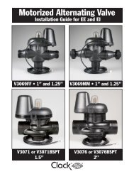
Order No. V3076 • Description: MOTOR ALT VLV 2 NPT REV2 or<br />
Order No. V3076BSPT • Description: MOTOR ALT VLV 2 BSPT REV2<br />
Drawing No. Order No. Description<br />
Quantity<br />
V3076 V3076BSPT<br />
1 V3073 MAV/NOHWBY COVER ASY 1 1<br />
2 V3476 WS MOTOR ASY 8 FT 1 1<br />
3 V3592 SCREW #8-3/4 PHPN T-25 SS 3 3<br />
4 V3262-01 WS1.5&2ALT/2BY REDUCGEARCVRASY 1 1<br />
5 V3110 WS1 DRIVE REDUCING GEAR 12X36 3 3<br />
6 V3264 WS2 BYPASS REDUCTION GEAR AXLE 3 3<br />
7 V3642 SCREW 1/4-20 X 1 1/4 BHSCS SS 4 4<br />
8 V3078 MAV/NOHWBY 2 DRIVE ASY 1 1<br />
9 V3634-01 MAV/NOHWBY 2 PISTON 1 1<br />
10 V3077 MAV/NOHWBY 2 STACK ASY 1 1<br />
11<br />
V3633-01<br />
V3633-01BSPT<br />
WS2 MAV BODY NPT<br />
WS2 MAV BODY BSPT<br />
1<br />
N/A<br />
N/A<br />
1<br />
Not Shown V3474 WS ALT CONNECT CORD 8FT BLK 1 1<br />
2<br />
4<br />
5<br />
6<br />
3<br />
7<br />
9<br />
10<br />
1<br />
11<br />
8<br />
•Operating Pressures:<br />
20 PSI Minimum / 125 PSI Maximum<br />
•Operating Temperatures:<br />
40°F Minimum / 110°F Maximum<br />
Piston Orientation 1<br />
Motorized Alternating Valve<br />
and No Hard Water Bypass<br />
Valve Confi gurations.<br />
Piston Orientation 2<br />
No Hard Water Bypass Valve<br />
Confi gurations.
<strong>WS2H</strong> and <strong>WS3</strong> Drawings and Service Manual Page 29<br />
Drawing No. Order No. Description<br />
Quantity<br />
V3083 V3083BSPT<br />
1 V3696 <strong>WS3</strong> MAV COVER 1 1<br />
2 V3476 WS MOTOR ASY 8 FT 1 1<br />
3 V3592 SCREW #8-3/4 PHPN T-25 SS 3 3<br />
4 V3262-01 WS 1.5&2ALT/2BY REDUCGEARCVRASY 1 1<br />
5 V3110 WS1 DRIVE REDUCING GEAR 12X36 3 3<br />
6 V3264 WS2 BYPASS REDUCTION GEAR AXLE 3 3<br />
7 V3789<br />
SCREW 3/8-16 X 1.75 BHCS SS<br />
(7/32” hex allen wrench required)<br />
4 4<br />
8 V3085 <strong>WS3</strong> MAV DRIVE CAP ASY 1 1<br />
9 V3695-01 <strong>WS3</strong> MAV PISTON 1 1<br />
10 V3084 <strong>WS3</strong> MAV STACK ASY 1 1<br />
11<br />
Sold<br />
Separately<br />
Order No. V3083 • Description: MOTOR ALT VLV 3 NPT or<br />
Order No. V3083BSPT • Description: MOTOR ALT VLV 3 BSPT<br />
V3693-01 <strong>WS3</strong> MAV BODY NPT 1 N/A<br />
V3693BSPT-01 <strong>WS3</strong> MAV BODY BSPT N/A 1<br />
V3475-12 <strong>WS2H</strong>/<strong>WS3</strong> SYSTEM CONNECTION CORD 12 FOOT RED<br />
V3475-24 <strong>WS2H</strong>/<strong>WS3</strong> SYSTEM CONNECTION CORD 24 FOOT BLUE<br />
V3475-36 <strong>WS2H</strong>/<strong>WS3</strong> SYSTEM CONNECTION CORD 36 YELLOW<br />
2<br />
4<br />
3<br />
5<br />
6<br />
7<br />
10<br />
9<br />
8<br />
1<br />
11<br />
•Operating Pressures:<br />
20 PSI Minimum / 125 PSI Maximum<br />
•Operating Temperatures:<br />
40°F Minimum / 110°F Maximum<br />
Piston Orientation 1<br />
Motorized Alternating Valve<br />
and No Hard Water Bypass<br />
Valve Confi gurations.<br />
Piston Orientation 2<br />
No Hard Water Bypass Valve<br />
Confi gurations.<br />
One must be used for twin<br />
tank operation.
Page 30 <strong>WS2H</strong> and <strong>WS3</strong> Drawings and Service Manual<br />
V3060 <strong>WS2H</strong> BYPASS AUTO NPT, V3060BSPT <strong>WS2H</strong> BYPASS AUTO BSPT,<br />
V3061BSPT <strong>WS2H</strong> BYPASS MANUAL BSPT and V3061 <strong>WS2H</strong> BYPASS MANUAL NPT<br />
Drawing No. Order No. Description<br />
Quantity<br />
V3060 V3061<br />
1 V3056 WS1.5&2ALT/2BYPASS AUTO CVRASY 1 N/A<br />
2 V3476 WS MOTOR ASY 8 FT 1 N/A<br />
3 V3272 <strong>WS2H</strong> SCREW 8X1 SS HEX SELF TAP 3 N/A<br />
4 V3262-01 WS1.5&2ALT/2BY REDUCGEARCVRASY 1 N/A<br />
5 V3110 WS1 DRIVE GEAR 12X36 3 N/A<br />
6 V3264 <strong>WS2H</strong> BYPASS REDUCTION GEAR AXLE 3 N/A<br />
7 V3292 <strong>WS2H</strong> SCREW BSHD SS 1/4-20X1-1/2 8 8<br />
8 V3059 WS1.5&2ALT/2BYPAS AUTODRIVEASY 1 N/A<br />
9 V3268 <strong>WS2H</strong> BYPASS COVER DOME MANUAL 1 2<br />
10 V3058 <strong>WS2H</strong> BYPASS MANUAL DRIVE ASY 1 2<br />
11<br />
V3057<br />
V3057BSPT<br />
<strong>WS2H</strong> BYPASS BODY ASY NPT<br />
<strong>WS2H</strong> BYPASS BODY ASY BSPT<br />
1 1<br />
Not Shown V3053 <strong>WS2H</strong> 2-1/2 GROOVELOCK CLAMP ASY 2 2<br />
Treated water is used for refi ll whether or<br />
not an auto or <strong>manual</strong> bypass is installed to<br />
either the inlet or outlet of a control valve.<br />
The Auto Drive Assembly may be connected<br />
to the inlet or outlet of the control valve to<br />
achieve no hard water bypass. If the Auto<br />
Drive Assembly is connected to the control<br />
valve:<br />
• inlet then all regeneration cycles occur<br />
with treated water.<br />
• outlet then all regeneration cycles except<br />
for refi ll occur with untreated water.<br />
B indictates BSPT<br />
N indicates NPT<br />
8<br />
7<br />
1<br />
6<br />
5<br />
4<br />
2<br />
3<br />
11<br />
10<br />
9<br />
7
<strong>WS2H</strong> and <strong>WS3</strong> Drawings and Service Manual Page 31<br />
V3053 WS2 2-1/2 GROOVELOCK CLAMP ASY<br />
Drawing No. Order No. Description Quantity<br />
1 V3053 WS2 2-1/2 GROOVELOCK CLAMP ASY 1<br />
2 V3290 WS2 GROOVE LOCK SEAL 2.5 1<br />
3 V3269 <strong>WS2H</strong> NUT 5/16-18 SS HEX 1<br />
4 V3293 <strong>WS2H</strong> WASHER SS 5/16 FLAT 1<br />
5 V3276 <strong>WS2H</strong> BOLT HEX SS 5/16-18X1-3/4 1<br />
Not Shown S3086 SILICONE LUBRICANT 1<br />
1<br />
2<br />
5<br />
3<br />
4
Page 32 <strong>WS2H</strong> and <strong>WS3</strong> Drawings and Service Manual<br />
<strong>WS2H</strong>/ <strong>WS3</strong> Error Codes<br />
Possible Errors<br />
Code Description<br />
1001 No Encoder Pulses<br />
1002 Unexpected Stall, Main Drive<br />
1003 Run Time To Long, Main Drive<br />
14001 Message Queue Full<br />
15003 Run Time To Long, Bypass Drive<br />
15010 Run Time To Short, Bypass Drive Could Not Drive Offl ine<br />
15011 Run Time To Short, Bypass Drive Could Not Drive Online<br />
16001 Communication Lost With Unit 2<br />
16002 Communication Lost With Unit 3<br />
16003 Communication Lost With Unit 4<br />
16004 Regen List Full<br />
17000 Run Time To Long, Separate Source Drive<br />
17002 Run Time To Short, Separate Source Drive<br />
18000 Reset Performed<br />
18001 Power Loss<br />
18002 Power Restored
<strong>WS2H</strong> and <strong>WS3</strong> Drawings and Service Manual Page 33<br />
<strong>WS2H</strong>/ <strong>WS3</strong> Trouble Shooting Guide<br />
Problem Possible Cause Solution<br />
1. No Display on POD<br />
2. POD does not display correct<br />
time of day<br />
3. Display does not indicate that<br />
water is fl owing. Refer to user<br />
instructions for how the display<br />
indicates water is fl owing<br />
4. Control valve regenerates at<br />
wrong time of day<br />
5. Time of day fl ashes on and off<br />
6. Control valve does not<br />
regenerate automatically when<br />
the REGEN button is depressed<br />
and held.<br />
a. No power at electric outlet<br />
b. Control valve Power Adapter not<br />
plugged into outlet or power cord<br />
end not connected to PC board<br />
connection<br />
c. Improper power supply<br />
d. Poor connection between POD<br />
connector and PC Board.<br />
e. Defective Power Adapter<br />
f. Defective PC Board<br />
a. Power Adapter plugged into electric<br />
outlet controlled by light switch<br />
b. Tripped breaker switch and/or<br />
tripped GFI<br />
c. Power outage<br />
d. Defective PC Board<br />
a. Bypass/ isolation valve in bypass<br />
position<br />
b. Meter is not connected to meter<br />
connection on PC Board<br />
c. Restricted/ stalled meter turbine<br />
d. Meter wire not installed securely<br />
into three pin connector<br />
e. Defective meter<br />
f. Defective PC Board<br />
a. Power outage<br />
b. Time of day not set correctly<br />
c. Time of regeneration set incorrectly<br />
d. Control valve set at “on 0”<br />
(immediate regeneration)<br />
a. Repair outlet or use working outlet<br />
b. Plug Power Adapter into outlet or<br />
connect power cord end to PC Board<br />
connection<br />
c. Verify proper voltage is being delivered<br />
to PC Board<br />
d. Check connector on POD, possible<br />
broken wire or terminal pin not inserted<br />
properly in connector. Clean pins on PC<br />
Board by plugging & unplugging the<br />
POD connector a few times to remove<br />
excess protective coating.<br />
e. Replace Power Adapter<br />
f. Replace PC Board<br />
a. Use uninterrupted outlet<br />
a. Power outage a. Reset time of day.<br />
a. Defective PC Board<br />
b. For the case of systems, another unit<br />
in regen would not allow another<br />
unit to go into regeneration.<br />
b. Reset breaker switch and/ or GFI switch<br />
c. Reset time of day<br />
d. Replace PC Board<br />
a. Turn bypass/ isolation handles to place<br />
in service position<br />
b. Connect meter to three pin connection<br />
labeled FLOW on PC Board<br />
c. Remove meter and check for rotation or<br />
foreign material<br />
d. Verify meter cable wires are installed<br />
securely into three pin connector<br />
labeled FLOW<br />
e. Replace meter<br />
f. Replace PC Board<br />
a. Reset time of day.<br />
b. Reset to correct time of day<br />
c. Reset regeneration time<br />
d. Check programming setting and reset to<br />
dEL (for a delayed regen time)<br />
a. Replace PC Board<br />
b. Wait for unit in regeneration to fi nish
Page 34 <strong>WS2H</strong> and <strong>WS3</strong> Drawings and Service Manual<br />
Problem Possible Cause Solution<br />
7. Control valve does not<br />
regenerate automatically but<br />
does when the REGEN button is<br />
depressed and held.<br />
8. Hard or untreated water is<br />
being delivered<br />
9. Control valve uses too much<br />
regenerant<br />
a. Bypass/ isolation valves in bypass<br />
position<br />
b. Meter is not connected to meter<br />
connection on PC Board<br />
c. Restricted/ stalled meter turbine<br />
d. Incorrect programming<br />
e. Meter wire not installed securely<br />
into three pin connector<br />
f. Defective meter<br />
g. Defective PC Board<br />
Check water quality directly at unit<br />
outlet<br />
1) Water quality is good<br />
a) Bypass/ isolation valves are<br />
open or faulty<br />
2) Water quality is poor<br />
a) Damaged seal/stack assembly<br />
3)<br />
b)<br />
c)<br />
Faulty riser tube or seal<br />
Control valve body type and<br />
piston type mix matched<br />
Media is exhausted, water quality<br />
is poor<br />
a) Higher than anticipated water<br />
usage<br />
b)<br />
c)<br />
Meter not registering<br />
No regenerant or low level of<br />
regenerant in regenerant tank<br />
d) Control fails to draw in<br />
regenerant<br />
e) Water quality fl uctuation<br />
f)<br />
Fouled media bed<br />
a. Improper refi ll setting or refi ll fi ll<br />
fl ow control is not sized properly<br />
b. Improper program settings<br />
c. Control valve regenerates<br />
frequently<br />
a. Turn bypass/ isolation valves handles to<br />
place in service position<br />
b. Connect meter to three pin connection<br />
labeled FLOW on PC Board<br />
c. Remove meter and check for rotation or<br />
foreign material<br />
d. Check for programming error<br />
e. Verify meter cable wires are installed<br />
securely into three pin connector<br />
labeled FLOW<br />
f. Replace meter<br />
g. Replace PC Board<br />
1) External Bypass Leak<br />
a) Fully close bypass/ isolation<br />
valves or replace<br />
2) Internal Bypass Leak<br />
a) Replace seal/stack assembly<br />
3)<br />
b)<br />
c)<br />
Verify seal placement &<br />
engagement with riser<br />
Verify proper control valve body<br />
type and piston type match<br />
No internal leaks<br />
a) Check program settings or<br />
diagnostics for abnormal water<br />
usage<br />
b) See Troubleshooting Guide #3<br />
c) Check refi ll setting in<br />
programming. Check refi ll fl ow<br />
control for restrictions or debris<br />
and clean or replace, check refi ll<br />
fl ow control rate for proper fi ll<br />
time.<br />
d) Refer to Troubleshooting Guide<br />
# 12<br />
e) Test water and adjust program<br />
values accordingly<br />
f) Replace media bed<br />
a. Check refi ll setting and check refi ll<br />
fl ow control for proper refi ll rate.<br />
b. Check program setting to make sure<br />
they are specifi c to the water quality<br />
and application needs<br />
c. Check for leaking fi xtures that may<br />
be exhausting capacity or system is<br />
undersized
<strong>WS2H</strong> and <strong>WS3</strong> Drawings and Service Manual Page 35<br />
Problem Possible Cause Solution<br />
a. Low water pressure<br />
a. Check incoming water pressure – water<br />
pressure must remain at minimum of<br />
25 psi<br />
b. Plugged, fouled, or incorrect b. Inspect and clean or replace injector,<br />
injector size<br />
or replace injector with correct size for<br />
the application<br />
c. Restricted drain line<br />
c. Check drain line for restrictions or<br />
debris and clean<br />
d. Check seal/ stack assembly and piston<br />
for damage and replace<br />
10. Residual regenerant being<br />
delivered to service<br />
11. Excessive water in<br />
regenerant tank<br />
12. Control valve fails to draw in<br />
regenerant<br />
13. Water running to drain<br />
14. Motor drives intermittently<br />
during regeneration.<br />
d. Damaged seal/ stack assembly or<br />
piston allowing leakage during<br />
draw<br />
e. Draw time too short<br />
f. Excessive refi ll<br />
g. Vacuum leak in draw line / elbow<br />
1)<br />
2)<br />
Tank is being overfi lled<br />
a) Improper program settings<br />
b) Missing refi ll fl ow controller<br />
Previous regenerant is not being<br />
drawn out<br />
a. Injector is plugged<br />
b. Faulty regenerant piston<br />
c. Regenerant line connection leak<br />
d. Drain line restriction or debris cause<br />
excess back pressure<br />
e. Drain line too long or too high<br />
f. Low water pressure<br />
g. Damaged seal/ stack assembly<br />
a. Power outage during regeneration<br />
or unit is currently in regeneration<br />
b. Damaged seal/ stack assembly<br />
c. Piston assembly failure<br />
d. Drive cap assembly not tightened<br />
properly<br />
e. Program proper draw time needed<br />
f. Program proper refi ll time needed<br />
g. Locate vacuum leak and fi x<br />
1) Excess from fi ll cycle<br />
a) Verify program settings<br />
b) Visual inspection / measure<br />
volume output into container<br />
2) See Troubleshooting Guide #12<br />
a. Remove injector and clean or replace<br />
b. Replace regenerant piston<br />
c. Inspect regenerant line for air leak<br />
d. Inspect drain line and clean to correct<br />
restriction<br />
e. Shorten length and/or height<br />
f. Check incoming water pressure – water<br />
pressure must remain at minimum of<br />
25 psi<br />
g. Inspect seal stack assembly for damage<br />
and replace<br />
a. Upon power being restored control will<br />
fi nish the remaining regeneration time.<br />
Reset time of day.<br />
b. Replace seal/ stack assembly<br />
c. Replace piston assembly<br />
d. Re-tighten the drive cap assembly<br />
a. Low power a. See Table 2 Software and Power Supply<br />
Compatibility
Page 36 <strong>WS2H</strong> and <strong>WS3</strong> Drawings and Service Manual<br />
Problem Possible Cause Solution<br />
15. Err – 1001 = Control unable<br />
to sense motor movement<br />
16. Err – 1002 = Control valve<br />
motor ran too short and was<br />
unable to fi nd the next cycle<br />
position and stalled<br />
a. Motor not inserted fully to engage<br />
pinion, motor wires broken or<br />
disconnected<br />
b. PC Board not properly snapped into<br />
drive bracket<br />
c. Missing reduction gears<br />
d. Damaged or dirty reduction gear<br />
refl ectors<br />
e. Faulty or dirty optics on back of PC<br />
board<br />
a. Foreign material is lodged in control<br />
valve<br />
b. Mechanical binding<br />
c. Main drive gear too tight<br />
d. Improper voltage being delivered to<br />
PC Board<br />
a. Disconnect power, make sure motor is<br />
fully engaged, check for broken wires,<br />
make sure two pin connector on motor<br />
is connected to the two pin connection<br />
on the PC Board labeled REGEN. Press<br />
NEXT and REGEN buttons for about 3<br />
seconds to resynchronize software with<br />
piston position.<br />
b. Properly snap PC Board into drive<br />
bracket and then Press NEXT and<br />
REGEN buttons for about 3 seconds<br />
to resynchronize software with piston<br />
position.<br />
c. Replace missing gears<br />
d. Clean or replace reduction gear<br />
e. Clean or replace PC Board<br />
a. Open up control valve and pull out<br />
piston assembly and seal/ stack<br />
assembly for inspection. Press NEXT<br />
and REGEN buttons for about 3<br />
seconds to resynchronize software with<br />
piston position.<br />
b. Check piston and seal/ stack assembly,<br />
check reduction gears, check drive<br />
bracket and main drive gear interface.<br />
Press NEXT and REGEN buttons<br />
for about 3 seconds to resynchronize<br />
software with piston position. Check<br />
that pinion is not pressed up tight<br />
against motor<br />
c. Loosen main drive gear. Press NEXT<br />
and REGEN buttons for about 3<br />
seconds to resynchronize software with<br />
piston position. Verify free motion<br />
by rotating main drive gear by hand,<br />
driving piston in and out<br />
d. Verify that proper voltage is being<br />
supplied. Press NEXT and REGEN<br />
buttons for about 3 seconds to<br />
resynchronize software with piston<br />
position.
<strong>WS2H</strong> and <strong>WS3</strong> Drawings and Service Manual Page 37<br />
Problem Possible Cause Solution<br />
a. Motor failure during a regeneration a. Check motor connections then Press<br />
NEXT and REGEN buttons for about 3<br />
seconds to resynchronize software with<br />
piston position.<br />
b. Foreign matter built up on piston b. Replace piston and stack assemblies.<br />
17. Err – 1003 = Control valve<br />
motor ran too long and was<br />
unable to fi nd the next cycle<br />
position<br />
and stack assemblies creating Press NEXT and REGEN buttons<br />
friction and drag enough to time out for about 3 seconds to resynchronize<br />
motor<br />
software with piston position.<br />
c. Drive bracket not snapped in c. Snap drive bracket in properly then<br />
properly and out of position enough press NEXT and REGEN buttons<br />
that reduction gears and drive gear for about 3 seconds to resynchronize<br />
do not interface<br />
software with piston position.<br />
d. Low voltage slowing drive d. See Table 2 Software and Power Supply<br />
Compatibility<br />
18. Err - 14001 = Message<br />
queue full<br />
19. Err -15003 = Motorized<br />
Bypass or MAV for NHBP valve<br />
motor ran too long and unable to<br />
fi nd the proper park position<br />
Motorized Alternating Valve =<br />
MAV<br />
No Hard Water Bypass = NHBP<br />
a. Master PC Board did not receive a<br />
response from slave units.<br />
a. Control valve programmed for<br />
ALT A or noHbP without having a<br />
motorized drive securely connected<br />
to the 2 pin terminal labeled<br />
“BYPASS” on the main PC Board<br />
b. Poor wire connection<br />
c. Excess drag causing timeout before<br />
stall<br />
d. Motorized Bypass or MAV for<br />
NHBP motor not fully engaged<br />
with reduction gears<br />
a. Press NEXT and REGEN buttons<br />
for about 3 seconds to resynchronize<br />
software with piston position.<br />
a. Press NEXT and REGEN buttons<br />
for about 3 seconds to resynchronize<br />
software with piston position. Then reprogram<br />
valve to proper setting<br />
b. Remove power and check connection<br />
for Motorized Bypass or MAV for<br />
NHBP motor to PC Board two pin<br />
connection labeled BYPASS. Make<br />
sure wires in connector are inserted<br />
securely and no wires are broken. Clean<br />
pins on PC Board by plugging and<br />
unplugging the connector a few times<br />
to remove excess protective coating.<br />
Press NEXT and REGEN buttons<br />
for about 3 seconds to resynchronize<br />
software with piston position.<br />
c. Open up Motorized Bypass or MAV for<br />
NHBP to check for obstructions<br />
d. Properly insert motor into casing, do<br />
not force into casing. Press NEXT and<br />
REGEN buttons for about 3 seconds<br />
to resynchronize software with piston<br />
position.
Page 38 <strong>WS2H</strong> and <strong>WS3</strong> Drawings and Service Manual<br />
Problem Possible Cause Solution<br />
20. Err – 15010 = Motorized<br />
Bypass or MAV for NHBP valve<br />
motor ran too short (stalled)<br />
while trying to drive off-line<br />
Motorized Alternating Valve =<br />
MAV<br />
No Hard Water Bypass = NHBP<br />
21. Err – 15011 = Motorized<br />
Bypass or MAV for NHBP valve<br />
motor ran too short (stalled)<br />
while trying to drive on-line<br />
Motorized Alternating Valve =<br />
MAV<br />
No Hard Water Bypass = NHBP<br />
a. Foreign material is lodged in<br />
Motorized Bypass or MAV for<br />
NHBP valve<br />
b. Mechanical binding<br />
a. Foreign material is lodged in<br />
Motorized Bypass or MAV for<br />
NHBP valve<br />
b. Mechanical binding<br />
a. Open up Motorized Bypass or MAV for<br />
NHBP and check for foreign material.<br />
Press NEXT and REGEN buttons<br />
for about 3 seconds to resynchronize<br />
software with piston position.<br />
b. Check poppet drive assembly or<br />
piston and seal/ stack assembly, check<br />
reduction gears, drive gear interface,<br />
and check Motorized Bypass or MAV<br />
for NHBP black drive pinion on motor.<br />
Press NEXT and REGEN buttons<br />
for about 3 seconds to resynchronize<br />
software with piston position.<br />
a. Open up Motorized Bypass or MAV for<br />
NHBP and check for foreign material.<br />
Press NEXT and REGEN buttons<br />
for about 3 seconds to resynchronize<br />
software with piston position.<br />
b. Check poppet drive assembly or<br />
piston and seal/ stack assembly, check<br />
reduction gears, drive gear interface,<br />
and check Motorized Bypass or MAV<br />
for NHBP black drive pinion on motor.<br />
Press NEXT and REGEN buttons<br />
for about 3 seconds to resynchronize<br />
software with piston position.
<strong>WS2H</strong> and <strong>WS3</strong> Drawings and Service Manual Page 39<br />
Problem Possible Cause Solution<br />
1) Correct all errors on satellite units<br />
before attempting to reset error on<br />
master<br />
a. System is programmed for the a. Pressing any button while in the # of<br />
wrong number of units or a Slave units error will enter the user into the<br />
unit is in “error # of units” mode setting screen. Adjust to the correct<br />
due to loss of power.<br />
units for the system and press NEXT to<br />
exit the set up screen. Press NEXT and<br />
22. # of units error:<br />
Communications has been<br />
broken with the unit specifi ed in<br />
the error message. These errors<br />
are logged as 16K series errors<br />
as follows:<br />
16001: error with unit 2<br />
16002: error with unit 3<br />
16003: error with unit 4<br />
b. Poor connection on PC Boards<br />
REGEN buttons for about 3 seconds<br />
to resynchronize software with piston<br />
position. Re-program valve to proper<br />
setting.<br />
b. Make sure wires in connector are<br />
inserted securely and no wires are<br />
broken. Clean pins on PC Board<br />
by plugging and unplugging the<br />
connector a few times to remove excess<br />
protective coating. Press NEXT and<br />
REGEN buttons for about 3 seconds<br />
to resynchronize software with piston<br />
position.<br />
c. More than one unit has determined c. Press NEXT and REGEN buttons<br />
that it is the master control<br />
for about 3 seconds to resynchronize<br />
software with piston position. Then reprogram<br />
each valve to operate as single<br />
individual unit. Re-program the control<br />
that is to be the master control and it<br />
will fi lter down the programming to the<br />
slave controls automatically.<br />
23. Err – 17000 = MAV for<br />
Separate Source valve motor<br />
ran too long while trying to fi nd<br />
proper park position<br />
a. Control valve programmed for “ON<br />
SEP In” with out having a MAV for<br />
separate source attached<br />
b. MAV for separate source motor<br />
wire not connected to System Board<br />
or poor connection<br />
c. MAV for separate source motor not<br />
fully engaged with reduction gears<br />
a. Press NEXT and REGEN buttons<br />
for about 3 seconds to resynchronize<br />
software with piston position. Reprogram<br />
valve to proper setting<br />
b. Remove power and check connection<br />
on MAV for separate source motor wire<br />
to System Board two pin connection<br />
labeled AUX DRIVE. Make sure wires<br />
in connector are inserted securely<br />
and no wires are broken. Clean pins<br />
on System Board by plugging and<br />
unplugging the connector a few times<br />
to remove excess protective coating.<br />
Press NEXT and REGEN buttons<br />
for about 3 seconds to resynchronize<br />
software with piston position.<br />
c. Properly insert motor into casing, do<br />
not force into casing. Press NEXT and<br />
REGEN buttons for about 3 seconds<br />
to resynchronize software with piston<br />
position.
Page 40 <strong>WS2H</strong> and <strong>WS3</strong> Drawings and Service Manual<br />
Problem Possible Cause Solution<br />
24. Err – 17002 = MAV for<br />
Separate Source valve motor<br />
ran too short while trying to fi nd<br />
proper park position<br />
25. Err – 18000 = Reset was<br />
performed, this error code will<br />
display in the diagnostics under<br />
the error log<br />
26. Err – 18001 = Power loss,<br />
this error code will display in the<br />
diagnostics under error log<br />
27. Err – 18002 = Power<br />
restored, this error code will<br />
display in the diagnostics under<br />
error log<br />
a. Foreign material is lodged in MAV<br />
for separate source valve<br />
b. Mechanical binding<br />
a. Press the NEXT and REGEN<br />
buttons for about 3 seconds to<br />
resynchronize software with piston<br />
position.<br />
a. When power is lost a signal is sent<br />
to log the power loss<br />
a. When power is restored a signal is<br />
sent to log the power being restored<br />
a. Open up MAV for separate source<br />
and check for foreign material. Press<br />
NEXT and REGEN buttons for about 3<br />
seconds to resynchronize software with<br />
piston position.<br />
b. Check poppet drive assembly or<br />
piston and seal/ stack assembly, check<br />
reduction gears, drive gear interface,<br />
and check MAV for separate source<br />
black drive pinion on motor. Press<br />
NEXT and REGEN buttons for about 3<br />
seconds to resynchronize software with<br />
piston position.
<strong>WS2H</strong> and <strong>WS3</strong> Drawings and Service Manual Page 41<br />
Flow Rate (gpm)<br />
Flow Rate (gpm)<br />
Flow Rate (gpm)<br />
Flow Rate (gpm)<br />
24<br />
22<br />
20<br />
18<br />
16<br />
14<br />
12<br />
10<br />
8<br />
6<br />
4<br />
2<br />
16<br />
14<br />
12<br />
10<br />
4<br />
3<br />
2<br />
1<br />
Order No. V3010-2A<br />
US Units<br />
Total<br />
Slow Rinse<br />
Draw<br />
0<br />
20 40 60 80 100 120<br />
Pressure (psi)<br />
Order No. V3010-2C<br />
US Units<br />
Total<br />
Slow Rinse<br />
0<br />
20 40 60 80 100 120<br />
8<br />
6<br />
4<br />
2<br />
7<br />
6<br />
5<br />
4<br />
3<br />
2<br />
1<br />
Draw<br />
Pressure (psi)<br />
Order No. V3010-2E<br />
US Units<br />
Total<br />
Slow Rinse<br />
Draw<br />
0<br />
20 40 60 80 100 120<br />
Pressure (psi)<br />
Order No. V3010-2G<br />
US Units<br />
Total<br />
Slow Rinse<br />
0<br />
20 40 60 80 100 120<br />
Draw<br />
Pressure (psi)<br />
Flow Rate (gpm)<br />
Flow Rate (gpm)<br />
6<br />
5<br />
4<br />
3<br />
2<br />
1<br />
Flow Rate (gpm)<br />
Flow Rate (gpm)<br />
44<br />
40<br />
36<br />
32<br />
28<br />
24<br />
20<br />
16<br />
12<br />
8<br />
4<br />
Order No. V3010-2B<br />
US Units<br />
Slow Rinse<br />
Total<br />
Draw<br />
0<br />
20 40 60 80 100 120<br />
12<br />
10<br />
8<br />
6<br />
4<br />
2<br />
Pressure (psi)<br />
Order No. V3010-2D<br />
US Units<br />
Total<br />
Slow Rinse<br />
Draw<br />
0<br />
20 40 60 80 100 120<br />
18<br />
16<br />
14<br />
12<br />
10<br />
8<br />
6<br />
4<br />
2<br />
Pressure (psi)<br />
Order No. V3010-2F<br />
US Units<br />
Total<br />
Slow Rinse<br />
Draw<br />
0<br />
20 40 60 80 100 120<br />
Pressure (psi)<br />
Order No. V3010-2H<br />
US Units<br />
Total<br />
Slow Rinse<br />
Draw<br />
0<br />
20 40 60 80<br />
Pressure (psi)<br />
100 120
Page 42 <strong>WS2H</strong> and <strong>WS3</strong> Drawings and Service Manual<br />
Flow Rate (lpm)<br />
Flow Rate (lpm)<br />
Flow Rate (lpm)<br />
Flow Rate (lpm)<br />
60<br />
50<br />
40<br />
30<br />
20<br />
10<br />
Order No. V3010-2E<br />
Metric Units<br />
Total<br />
Slow Rinse<br />
0<br />
100 200 300 400 500 600 700 800 900<br />
90<br />
80<br />
70<br />
60<br />
50<br />
40<br />
30<br />
20<br />
10<br />
16<br />
14<br />
12<br />
10<br />
8<br />
6<br />
4<br />
2<br />
Order No. V3010-2A<br />
Metric Units<br />
Total<br />
Draw<br />
Draw<br />
Pressure (kPa)<br />
Slow Rinse<br />
0<br />
100 200 300 400 500 600 700 800 900<br />
27<br />
24<br />
21<br />
18<br />
15<br />
12<br />
9<br />
6<br />
3<br />
Pressure (kPa)<br />
Order No. V3010-2C<br />
Metric Units<br />
Total<br />
Slow Rinse<br />
Draw<br />
0<br />
100 200 300 400 500 600 700 800 900<br />
Pressure (kPa)<br />
Order No. V3010-2G<br />
Metric Units<br />
Slow Rinse<br />
0<br />
100 200 300 400 500 600 700 800 900<br />
Total<br />
Draw<br />
Pressure (kPa)<br />
Flow Rate (lpm)<br />
Flow Rate (lpm)<br />
21<br />
18<br />
15<br />
12<br />
Flow Rate (lpm)<br />
Flow Rate (lpm)<br />
160<br />
140<br />
120<br />
100<br />
80<br />
60<br />
40<br />
20<br />
9<br />
6<br />
3<br />
Order No. V3010-2B<br />
Metric Units<br />
Total<br />
Slow Rinse<br />
0<br />
100 200 300 400 500 600 700 800 900<br />
70<br />
60<br />
50<br />
40<br />
30<br />
20<br />
10<br />
40<br />
35<br />
30<br />
25<br />
20<br />
15<br />
10<br />
5<br />
Draw<br />
Pressure (kPa)<br />
Order No. V3010-2D<br />
Metric Units<br />
Total<br />
Slow Rinse<br />
0<br />
100 200 300 400 500 600 700 800 900<br />
Draw<br />
Pressure (kPa)<br />
Order No. V3010-2F<br />
Metric Units<br />
Total<br />
Slow Rinse<br />
Draw<br />
0<br />
100 200 300 400 500 600 700 800 900<br />
Pressure (kPa)<br />
Order No. V3010-2H<br />
Metric Units<br />
Slow Rinse<br />
0<br />
100 200 300 400 500 600 700 800 900<br />
Pressure (kPa)<br />
Total<br />
Draw
<strong>WS2H</strong> and <strong>WS3</strong> Drawings and Service Manual Page 43
Page 44 <strong>WS2H</strong> and <strong>WS3</strong> Drawings and Service Manual<br />
Revision History:<br />
3/25/2010<br />
PAGE15:<br />
Not Shown V3461 <strong>WS2H</strong>/3 AC ADAPTER<br />
Not Shown V3461EU <strong>WS2H</strong>/3 AC ADAPTER EU<br />
Not Shown V3461UK <strong>WS2H</strong>/3 AC ADAPTER UK<br />
6/10/2010<br />
PAGE 4:<br />
Table 1<br />
Output Voltage 20V or 24V AC see Table 2<br />
PAGE 5:<br />
Added Table 2<br />
PAGE 16:<br />
Revised table<br />
V3461 <strong>WS2H</strong>/3 AC ADAPTER (shipped less cord) 1<br />
V3461EU <strong>WS2H</strong>/3 AC ADAPTER EU<br />
7/28/2010<br />
PAGE 16:<br />
6 V3107-01 WS1 MOTOR ASY 1<br />
1<br />
Form No. V3215 – 7/28/2010<br />
U.S. Patents: 6,402,944; 6,444,127; and 6,776,901