Water Specialist 1.5", 2" and 2L Control Valve ... - ClackValves.Net
Water Specialist 1.5", 2" and 2L Control Valve ... - ClackValves.Net
Water Specialist 1.5", 2" and 2L Control Valve ... - ClackValves.Net

You also want an ePaper? Increase the reach of your titles
YUMPU automatically turns print PDFs into web optimized ePapers that Google loves.
Page 14 WS1.5, 2 & <strong>2L</strong> Drawings & Service Man u al<br />
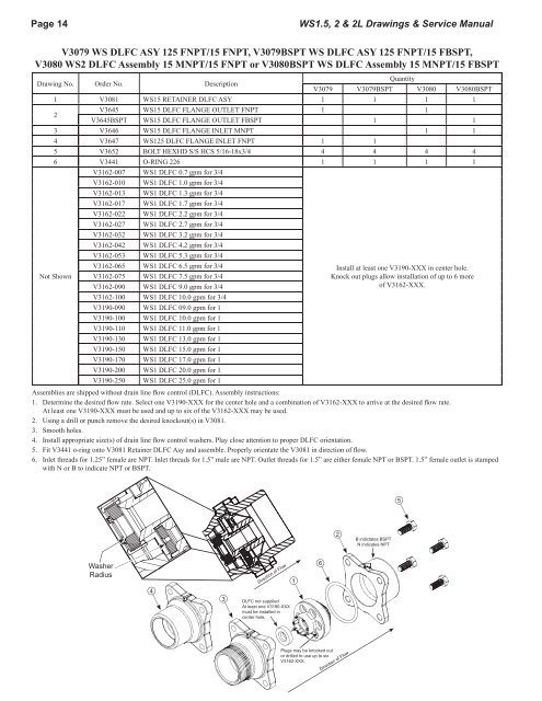
V3079 WS DLFC ASY 125 FNPT/15 FNPT, V3079BSPT WS DLFC ASY 125 FNPT/15 FBSPT,<br />
V3080 WS2 DLFC Assembly 15 MNPT/15 FNPT or V3080BSPT WS DLFC Assembly 15 MNPT/15 FBSPT<br />
Drawing No. Order No. Description<br />
V3079<br />
Quantity<br />
V3079BSPT V3080 V3080BSPT<br />
1 V3081 WS15 RETAINER DLFC ASY 1 1 1 1<br />
2<br />
V3645<br />
V3645BSPT<br />
WS15 DLFC FLANGE OUTLET FNPT<br />
WS15 DLFC FLANGE OUTLET FBSPT<br />
1<br />
1<br />
1<br />
1<br />
3 V3646 WS15 DLFC FLANGE INLET MNPT 1 1<br />
4 V3647 WS125 DLFC FLANGE INLET FNPT 1 1<br />
5 V3652 BOLT HEXHD S/S HCS 5/16-18x3/4 4 4 4 4<br />
6 V3441 O-RING 226 1 1 1 1<br />
Not Shown<br />
V3162-007 WS1 DLFC 0.7 gpm for 3/4<br />
V3162-010 WS1 DLFC 1.0 gpm for 3/4<br />
V3162-013 WS1 DLFC 1.3 gpm for 3/4<br />
V3162-017 WS1 DLFC 1.7 gpm for 3/4<br />
V3162-022 WS1 DLFC 2.2 gpm for 3/4<br />
V3162-027 WS1 DLFC 2.7 gpm for 3/4<br />
V3162-032 WS1 DLFC 3.2 gpm for 3/4<br />
V3162-042 WS1 DLFC 4.2 gpm for 3/4<br />
V3162-053 WS1 DLFC 5.3 gpm for 3/4<br />
V3162-065 WS1 DLFC 6.5 gpm for 3/4<br />
V3162-075 WS1 DLFC 7.5 gpm for 3/4<br />
V3162-090 WS1 DLFC 9.0 gpm for 3/4<br />
V3162-100 WS1 DLFC 10.0 gpm for 3/4<br />
V3190-090 WS1 DLFC 09.0 gpm for 1<br />
V3190-100 WS1 DLFC 10.0 gpm for 1<br />
V3190-110 WS1 DLFC 11.0 gpm for 1<br />
V3190-130 WS1 DLFC 13.0 gpm for 1<br />
V3190-150 WS1 DLFC 15.0 gpm for 1<br />
V3190-170 WS1 DLFC 17.0 gpm for 1<br />
V3190-200 WS1 DLFC 20.0 gpm for 1<br />
V3190-250 WS1 DLFC 25.0 gpm for 1<br />
Install at least one V3190-XXX in center hole.<br />
Knock out plugs allow installation of up to 6 more<br />
of V3162-XXX.<br />
Assemblies are shipped without drain line fl ow control (DLFC). Assembly instructions:<br />
1. Determine the desired fl ow rate. Select one V3190-XXX for the center hole <strong>and</strong> a combination of V3162-XXX to arrive at the desired fl ow rate.<br />
At least one V3190-XXX must be used <strong>and</strong> up to six of the V3162-XXX may be used.<br />
2. Using a drill or punch remove the desired knockout(s) in V3081.<br />
3. Smooth holes.<br />
4. Install appropriate size(s) of drain line fl ow control washers. Play close attention to proper DLFC orientation.<br />
5. Fit V3441 o-ring onto V3081 Retainer DLFC Asy <strong>and</strong> assemble. Properly orientate the V3081 in direction of fl ow.<br />
6. Inlet threads for 1.25” female are NPT. Inlet threads for 1.5” male are NPT. Outlet threads for 1.5” are either female NPT or BSPT. 1.5” female outlet is stamped<br />
with N or B to indicate NPT or BSPT.<br />
Washer<br />
Radius<br />
4<br />
3<br />
Direction of Flow<br />
DLFC not supplied.<br />
At least one V3190-XXX<br />
must be installed in<br />
center hole.<br />
1<br />
6<br />
Plugs may be knocked out<br />
or drilled to use up to six<br />
V3162-XXX.<br />
2<br />
Direction of Flow<br />
B indictates BSPT<br />
N indicates NPT<br />
5