Clack CI programing manual - Dime WATER
Clack CI programing manual - Dime WATER
Clack CI programing manual - Dime WATER

You also want an ePaper? Increase the reach of your titles
YUMPU automatically turns print PDFs into web optimized ePapers that Google loves.
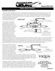
Water Specialist <strong>CI</strong><br />
Control Valve<br />
Programming and Cover Drawing Manual
<strong>CI</strong> Man u al Page 3<br />
Table of Contents<br />
<strong>CI</strong> Front Cover and Drive Assembly .......................................................................................................................4<br />
OEM General Instructions .......................................................................................................................................5<br />
OEM Cycle Sequence ..............................................................................................................................................6<br />
OEM Softener System Setup .................................................................................................................................11<br />
Setting Options Table .............................................................................................................................................13<br />
OEM Filter System Setup ......................................................................................................................................14<br />
Installer Display Settings .......................................................................................................................................16<br />
User Display Settings ............................................................................................................................................17<br />
Diagnostics ............................................................................................................................................................20<br />
Valve History .........................................................................................................................................................21
Page 4 <strong>CI</strong> Man u al<br />
<strong>CI</strong> Front Cover and Drive Assembly<br />
Drawing No. Order No. Description Quantity<br />
1 V3175<strong>CI</strong>-01 WS1<strong>CI</strong> FRONT COVER ASSEMBLY 1<br />
2 V3107-01 WS1 MOTOR 1<br />
3 V3106-01 WS1 DRIVE BRACKET & SPRING CLIP 1<br />
4 V3108<strong>CI</strong>-04BOARD WS1 THRU2L/2 <strong>CI</strong> PCB ALT REPLACE SERCOM 1<br />
5 V3110 WS1 DRIVE REDU<strong>CI</strong>NG GEAR 12X36 3<br />
6 V3109 WS1 DRIVE GEAR COVER 1<br />
V3186 WS1 AC ADAPTER 110V-12V<br />
Not Shown<br />
V3186EU<br />
V3186UK<br />
WS1 AC ADAPTER 220-240V-12V EU<br />
WS1 AC ADAPTER 220-240V-12V UK<br />
1<br />
V3186-01 WS1 AC ADAPTER CORD ONLY<br />
Not Shown V3178 WS1 DRIVE BACKPLATE 1<br />
When replacing the battery, align<br />
positives and push down to fully seat.<br />
Battery Fully Seated<br />
1<br />
AC Adapter U.S. International<br />
Supply Voltage 120 V AC 230V AC<br />
Supply Frequency 60 Hz 50 Hz<br />
Output Voltage 12 V AC 12 V AC<br />
Output Current 500 mA 500 mA<br />
Correct<br />
Battery<br />
Orientation<br />
2<br />
Battery replacement is<br />
3 volt lithium coin cell<br />
type 2032.<br />
4<br />
5<br />
3<br />
6
<strong>CI</strong> Man u al Page 5<br />
OEM General Instructions<br />
The control valve offers multiple procedures that allow the valve to be modifi ed to suit the needs of the installation. These<br />
procedures are:<br />
• OEM Cycle Sequence<br />
• OEM Softener System Setup<br />
• OEM Filter System Setup<br />
• Installer Display Settings<br />
• User Display Settings<br />
• Diagnostics<br />
• Valve History<br />
Once the OEM Cycle Sequence has been set, the other procedures can be accessed in any order. Details on each of the procedures<br />
are provided on the following pages.<br />
To “lock out” access to diagnostic and valve history displays and modifi cations to settings except hardness, day override, time of<br />
regeneration and time of day by anyone but the manufacturer, press ▼, NEXT, ▲, and SET CLOCK in sequence after settings<br />
are made. To “unlock”, so other displays can be viewed and changes can be made, press ▼, NEXT, ▲, and SET CLOCK in<br />
sequence.<br />
When in operation normal user displays such as time of day, volume remaining before regeneration, present fl ow rate or days<br />
remaining before regeneration are shown. When stepping through a procedure, if no buttons are pressed within fi ve minutes, the<br />
display returns to a normal user display. Any changes made prior to the fi ve minute time out are incorporated.<br />
To quickly exit OEM Softener Setup, OEM Filter Setup, Installer Display Settings, Diagnostics or Valve History press SET<br />
CLOCK. Any changes made prior to the exit are incorporated.<br />
When desired, all programming and all information in Diagnostics may be reset to defaults when the valve is installed in a<br />
new location. To reset to defaults, press NEXT and ▼ buttons simultaneously to go to the Softening/Filtering screen. Press<br />
▲ and ▼ simultaneously to reset diagnostic values and all programming to defaults. Screen will return to User Display.<br />
Sometimes it is desirable to have the valve initiate and complete two regenerations within 24 hours and then return to the preset<br />
regeneration procedure. It is possible to do a double regeneration if the control valve is set to “NORMAL” or “NORMAL + on 0”<br />
in OEM Softener System Setup or OEM Filter System Setup. To do a double regeneration:<br />
1. Press the “REGEN” button once. REGEN TODAY will fl ash on the display.<br />
2. Press and hold the “REGEN” button for three seconds until the valve regeneration initiates.<br />
Once the valve has completed the immediate regeneration, the valve will regenerate one more time at the preset regeneration time.
Page 6 <strong>CI</strong> Man u al<br />
STEP 1CS Step 1CS – Press NEXT and ▼ simultaneously for 3 seconds and release. Then press NEXT and ▼<br />
simultaneously for 3 seconds and release. If screen in Step 2CS does not appear in 5 seconds the lock<br />
on the valve is activated. To unlock press ▼, NEXT, ▲, and SET CLOCK in sequence, then press<br />
NEXT and ▼ simultaneously for 3 seconds and release. Then press NEXT and ▼ simultaneously for 3<br />
seconds and release.<br />
STEP 2CS<br />
STEP 3CS<br />
OEM Cycle Sequence<br />
OEM Cycle Sequence instructions allows the OEM to set the order of<br />
the cycle. The OEM Softener System Setup or the OEM Filter System<br />
Setup allow the OEM to set how long cycles will last. The OEM may<br />
choose up to 9 cycles in any order.<br />
END must be used as the last cycle option. The SERVICE cycle<br />
should only be used in brine prefi ll applications.<br />
Cycle Options<br />
BACKWASH DN BRINE FILL<br />
RINSE UP BRINE SOFTENING<br />
(WS1 Only) OR FILTERING<br />
The upfl ow cycle can not be used on the WS1.25, WS1.5, WS2L or WS2 control valves. The V3407 piston used on the WS1.25,<br />
WS1.5 and WS2L is designed for downfl ow use only. The components for converting the operation of a WS2 valve from<br />
downfl ow to upfl ow are not yet available. For WS1 valves, prior to selecting DN brine or UP brine or not selecting a regenerant<br />
fl ow cycle, verify the correct valve body, main piston, regenerant piston, and stack are being used, and that the injector or injector<br />
plug(s) are in the correct locations. See Valve Body Compliance Table in WS1 & WS1.25 OEM Drawings and Service Manual.<br />
The following is an example of how to set a valve so that when regeneration is initiated BACKWASH occurs fi rst, dn BRINE<br />
occurs second, RINSE occurs third, and FILL occurs fourth.<br />
Step 2CS – Use the ▲ or ▼ to select 25 for WS1 valve, 32 for WS1.25 valve, 38 for WS1.5 valve, 50<br />
for WS2 or 50L for a WS2L valve. 1<br />
Note: When using the WS2 valve, if “50L” is set instead of “50”, when the valve is in regeneration and<br />
the piston drives to the “DRAW” cycle the piston will stall and generate a 1002 error code. Clear the<br />
error code by pressing “NEXT” and “REGEN” buttons simultaneously until the valve resets, then reprogram<br />
valve to proper valve type setting. Press NEXT to go to Step 3CS. Press REGEN to exit OEM<br />
cycle sequence.<br />
Step 3CS – When 50 or 50L is selected, and additional screen will appear. It is used to select which size<br />
fl ow meter is to be used with the valve, 1.5” (38) or 2” (50).<br />
Press NEXT to go to Step 4CS. Press REGEN to return to previous step.<br />
¹ When using the WS2 control valve, the circuit board software must have meter selection choices of 50 and 50L. The WS2 valve must be set<br />
for the 50 meter selection during programming. If the software version does not have both the 50 and 50L selections, consult your equipment<br />
supplier for a replacement circuit board. When using the WS2L valve with older version software that does not have both 50 and 50L selection<br />
choices, the valve must be set to 50 if using a 2” meter or 38 if using a 1.5” meter during programming. If a WS2L valve is being used with<br />
newer version software that has both 50 and 50L selection choices, the valve must be set for 50L during programming.<br />
END
<strong>CI</strong> Man u al Page 7<br />
STEP 4CS<br />
Step 4CS – Allows selection of one of the following using the ▲ or ▼ buttons:<br />
• the Control Valve to have no hard water bypass;<br />
• the Control Valve to act as an alternator; or<br />
• the Control Valve to have a separate source during the regeneration cycle; or<br />
• the Control Valve to operate with the <strong>Clack</strong> System Controller.<br />
Select OFF when none of these features are used.<br />
Only use <strong>Clack</strong> No Hard Water Bypass Valves or <strong>Clack</strong> Motorized Alternating Valves (MAV) with<br />
these selections. <strong>Clack</strong> No Hard Water Bypass Valves (1” or 1.25” V3070FF or V3070FM) are not<br />
designed to be used with the alternator or separate source functions. The V3063 and V3063BSPT<br />
motorized alternating valves are not designed to be used as a no hard water bypass or separate source<br />
inlet if the pressure differential is more than 60 psi.<br />
Confi guring the Control Valve for No Hard Water Bypass Operation:<br />
Select nHbP for control operation. For no hard water bypass operation the three wire connector is not<br />
used.<br />
Selection requires that a connection to MAV or a <strong>Clack</strong> No Hard Water Bypass Valve is made to the<br />
two pin connector labeled ALTERNATOR DRIVE located on the printed circuit board. If using a<br />
MAV, the A port of the MAV must be plugged and the valve outlet connected to the B port. When<br />
set to nHbP the MAV will be driven closed before the fi rst regeneration cycle that is not FILL or<br />
SOFTENING or FILTERING, and be driven open after the last regeneration cycle that is not FILL.<br />
NOTE: If the control valve enters into an error state during regeneration mode, the no hard water<br />
bypass valve will remain in its current state until the error is corrected and reset.<br />
Confi guring the Control Valve for Separate Source Operation:<br />
Select SEPS for control operation. For separate source operation the three wire connector is not used.<br />
Selection requires that a connection to a <strong>Clack</strong> Motorized Alternator Valve (MAV) is made to the two<br />
pin connector labeled ALTERNATOR DRIVE located on the printed circuit board. The C port of the<br />
MAV must be connected to the valve inlet and the A port connected to the separate source used during<br />
regeneration. The B port must be connected to the feed water supply.<br />
When set to SEPS the MAV will be driven closed before the fi rst regeneration cycle, and be driven<br />
open after the last regeneration cycle.<br />
NOTE: If the control valve enters into an error state during regeneration mode, the MAV will remain in<br />
its current state until the error is corrected and reset.<br />
Selecting the Control Valve to act as an alternator:<br />
Software Rev Level 320.0 and higher = Use 3-wire Interconnect Cable for all communication between units.<br />
Software Rev Level 319.5 and lower = Use 2-wire Interconnect Cables for twin alternators with independent fl ow meters.<br />
Prior to starting the programming steps, connect the interconnect cable to each control valve board’s three pin connector labeled<br />
‘INTERCONNECT’. Also connect the meter cord to either control valve to the three pin connector labeled ‘METER’.<br />
Softener Valve Programming Steps<br />
OEM Cycle<br />
Sequence<br />
OEM Cycle<br />
Sequence<br />
Softener System<br />
Setup<br />
Softener System<br />
Setup<br />
Softener System<br />
Setup<br />
Installer Display<br />
Setting<br />
Step 4CS<br />
Set to ALTA<br />
Connect ALTA valve to the MAV’s A port and<br />
connect the MAV’s two pin wire connector to<br />
the two pin connector labeled “DRIVE” on the<br />
ALTA valve<br />
Set to ALTb<br />
Connect ALTb valve to the MAV’s B port. No<br />
connections between the ALTB valve and the<br />
MAV are made.<br />
Step 6CS Select ppm, FH or dH Select ppm, FH or dH<br />
Step 7S Set Volume Capacity Set Volume Capacity<br />
Step 8S Set to ‘AUTO’ Set to ‘AUTO’<br />
Step 9S Set regeneration time option to ‘On O’. Set regeneration time option to ‘On O’.<br />
Step 4I Set Day Over ride to “oFF” Set Day Over ride to “oFF”
Page 8 <strong>CI</strong> Man u al<br />
If set up for a fi lter, in Step 7F set Volume Capacity in M 3 ; in Step 8F select Regeneration Time Option “on 0”; and in Step 4I<br />
select Day Override “oFF”.<br />
NOTE: If the control valve is in an error state during regeneration mode the MAV will close the B port and keep open the A port<br />
until the error is corrected and reset.<br />
For <strong>Clack</strong> Corporation alternator systems using WS1, WS1.25,<br />
WS1.5, and WS2L valves there will be an option to delay the last<br />
two cycles of regeneration (only “Rinse” and “Fill”). This feature<br />
splits the regeneration into two portions. The fi rst portion of the<br />
regeneration will start immediately and all programmed cycles<br />
before the “Rinse” and “Fill” cycles will be performed. After<br />
all programmed cycles before “Rinse” and “Fill” are completed<br />
the control valve will drive to the service position (displaying<br />
“Delayed Rinse + Fill Pending”). When the volume of the online<br />
unit is depleted to 10% of its programmed capacity, the<br />
control valve will be triggered to fi nish the second portion of the<br />
regeneration. Once “Rinse” and “Fill” are completed, the valve<br />
will re-enter Standby mode until requested to come on-line for<br />
Service.<br />
For <strong>Clack</strong> Corporation alternator systems using the WS2 valve,<br />
when NEXT is pressed after selecting ALTA or ALTB, a display<br />
will allow the user to set the amount of pre-service rinse time for<br />
the stand by tank just prior to returning to service.<br />
Retracted<br />
Valve “A” in Service Position =<br />
MAV piston rod Retracted<br />
Extended<br />
Valve “B” in Service Position = MAV<br />
piston rod Extended<br />
WS1, WS1.25, WS1.5,<br />
WS2L Valves<br />
WS2<br />
Valve<br />
Note: <strong>Clack</strong> Twin Alternator Operations<br />
• Twin alternating systems can be programmed with a day override setting combined with the normal volume-based<br />
regeneration programming. A twin alternating system in this confi guration will then regenerate based on the volume used or<br />
the day override if there is a period of low water usage.<br />
• Twin alternating systems can be programmed as a time clock only based regenerating system. In this confi guration, the days<br />
remaining are counted only on the unit that is in service. The unit in Stand-by Mode only notes days in diagnostics, which<br />
results in time clock only twin regeneration initiation.<br />
• Twin alternating systems can be programmed for a delayed regeneration time. The system will allow an immediate transfer<br />
of the MAV to switch tanks and place a fully regenerated unit in service once a unit becomes exhausted. The exhausted unit<br />
will then be placed into Stand-by Mode and allowed to have a delayed regeneration at the pre-set time.
<strong>CI</strong> Man u al Page 9<br />
Confi guring the Control Valve to operate with <strong>Clack</strong> System Controller:<br />
Select SYS to link the Control Valve to the <strong>Clack</strong> System Controller. For communication between<br />
the Control Valve and the System Controller, a three-wire communication cable is required.<br />
Press NEXT to go to Step 5CS. Press REGEN to return to previous step.<br />
STEP 5CS Step 5CS – Allows selection of one of the following using the ▲ or ▼ buttons:<br />
• an outside signal to initiate a regeneration;<br />
• an outside signal to prevent or delay regeneration.<br />
Selection only matters if a connection is made to the two pin connector labeled DP SWITCH located on<br />
the printed circuit board. Following is an explanation of the options:<br />
OFF - Feature not used.<br />
NOTE: In a twin alternating system each control must have a separate dP signal or dP switch.<br />
One dP signal or one dP switch cannot be used for both controls.<br />
dPon0 – If the dP switch is closed for an accumulative time of 2 minutes a regeneration will be<br />
signaled to the unit. In a twin alternating system the MAV will transition fi rst to switch units so that<br />
the signaled unit can start regeneration. After the MAV has fully transitioned, the regeneration begins<br />
immediately. Note: For WS1 – WS2L control valves programmed for twin alternating: if the dP function<br />
“dPon0” is set, the Delayed Rinse and Fill feature is not available.<br />
dPdEL – If the dP switch is closed for an accumulative time of 2 minutes a regeneration will occur at<br />
the scheduled delayed regeneration time. In a twin alternating system once the dP switch is triggered<br />
the PC Board will display “REGEN TODAY” and when the delayed regen time comes the control will<br />
switch tanks and the triggered unit will then go into regeneration. Note: For WS1 – WS2L control<br />
valves programmed for twin alternating: if the dP function “dPdEL” is set, the Delayed Rinse and Fill<br />
feature is not available.<br />
HoLd – If the dP switch is closed a regeneration will be prevented from occurring while there is switch<br />
closure. In a twin alternating system the regeneration of a unit can be prevented upon switch closure.<br />
If the unit depletes the capacity down to zero, it will not be allowed to switch tanks to regenerate until<br />
the switch is open. Note: For WS1 – WS2L control valves programmed for twin alternating the Delayed<br />
Rinse and Fill feature can be set in conjunction with the “HoLd” if desired.<br />
Press NEXT to go to Step 6CS. Press REGEN to return to previous step.
Page 10 <strong>CI</strong> Man u al<br />
STEP 6CS<br />
STEP 7CS<br />
STEP 8CS<br />
STEP 9CS<br />
STEP 10CS<br />
STEP 11CS<br />
RETURN TO NORMAL MODE<br />
Step 6CS – Determine the measurement to calculate volumetric capacity. The<br />
choices are:<br />
ppm parts per million<br />
FH French degrees<br />
dH German degrees<br />
-nA- Using -nA- will allow the OEM to directly place the volume of water<br />
treated in place of system capacity in the OEM Softener System Setup level.<br />
NOTE: If control is going to be used in a fi lter application none of these<br />
settings can be used.<br />
Press NEXT to go to Step 7CS. Press REGEN to return to previous step.<br />
Step 7CS – Press the ▼ or ▲ buttons until BACKWASH appears. Press NEXT to go to Step 8CS.<br />
Press REGEN to return to previous step.<br />
Step 8CS - Press the ▼ or ▲ buttons until dn BRINE appears. For a WS1 control valve; prior to<br />
selecting a regenerant fl ow cycle, verify the correct valve body, main piston, regenerant piston and<br />
stack are being used, and the injector or injector plug(s) are in the correct location. Refer to WS1 &<br />
WS1.25 Drawings and Service Manual, Valve Body Compliance Table. Press NEXT to go to Step 9CS.<br />
Press REGEN to return to previous step.<br />
Step 9CS - Press the ▼ or ▲ buttons until RINSE appears. Press NEXT to go to Step 10CS. Press<br />
REGEN to return to previous step.<br />
Step 10CS - Press the ▼ or ▲ buttons until FILL appears. Press NEXT to go to Step 11CS. Press<br />
REGEN to return to previous step.<br />
Step 11CS - Press the ▼ or ▲ buttons until END appears. Press NEXT to exit OEM Cycle Sequence.<br />
Press REGEN to return to previous step.
<strong>CI</strong> Man u al Page 11<br />
OEM Softener System Setup<br />
In OEM Softener System Setup the OEM chooses the time for the cycles selected in OEM Cycle Sequence and specifi es other<br />
operating parameters for the system. The upper and lower limits of the allowable values for the cycles are as follows:<br />
Cycle Options Units Lower/Upper Limit<br />
Backwash Minutes 1 to 120<br />
Rinse (fast) Minutes 1 to 120<br />
dn Brine (combination of brining and slow rinse) Minutes 1 to 180<br />
up Brine (combination of brining and slow rinse) Minutes 1 to 180<br />
Fill for all valves except WS2 Kg 0.05 to 90.00<br />
Fill for WS2 valves Minutes 0.1 to 99.0<br />
Service<br />
Note: Fill is in Kilograms of salt (except for WS2).<br />
Minutes 1 to 480<br />
Since no time is associated with the END cycle, the END cycle will not appear in the OEM Softener System Setup sequence.<br />
STEP 1S<br />
STEP 2S<br />
STEP 3S<br />
STEP 4S<br />
STEP 5S<br />
Step 1S – Press NEXT and ▼ simultaneously for 3 seconds and release. If screen in Step 2S does not<br />
appear in 5 seconds the lock on the valve is activated. To unlock press ▼, NEXT, ▲, and SET CLOCK<br />
in sequence, then press NEXT and ▼ simultaneously for 3 seconds and release.<br />
Step 2S – Choose SOFTENING using the ▼ or ▲ button. Press NEXT to go to Step 3S. Press REGEN<br />
to exit OEM Softener System Setup.<br />
Step 3S – Select the time for the fi rst cycle (which in this example is BACKWASH) using the ▼ or ▲<br />
button. Press NEXT to go to Step 4S. Press REGEN to return to previous step.<br />
Step 4S – Select the time for the second cycle (which in this example is dn BRINE) using the ▼ or ▲<br />
button. Press NEXT to go to Step 5S. Press REGEN to return to previous step.<br />
NOTE: The display will fl ash between cycle number and time, and brine direction (dn).<br />
Step 5S – Select the time for the third cycle (which in this example is RINSE) using the ▼ or ▲ button.<br />
Press NEXT to go to Step 6S. Press REGEN to return to previous step.<br />
STEP 6S Step 6S – Select the Kg or MIN for the fourth cycle (which in this example is FILL) using the ▼ or ▲<br />
button. When both 50 and 50L are options in Step 2CS, and 50 is selected, FILL is in minutes. WS2<br />
valves are shipped from the factory with a refi ll fl ow contol of 2.2 gpm (8.3 lpm). Press NEXT to go to<br />
Step 7S. Press REGEN to return to previous step.
Page 12 <strong>CI</strong> Man u al<br />
STEP 7S<br />
STEP 8S<br />
STEP 9S<br />
STEP 10S<br />
RETURN TO NORMAL MODE<br />
Step 7S – Set System Capacity using the ▼ or ▲ button. See chart. The System<br />
Capacity setting should be based on the volume of resin and Kg of salt fi ll set in<br />
Step 6S. When using ppm, dH, or FH the system capacity and hardness levels<br />
entered are used to determine the Volume Capacity. Press NEXT to go to Step 8S.<br />
Press REGEN to return to previous step.<br />
Setting Units<br />
Kg of<br />
PPM CaCO3 nA M 3<br />
dH or FH H*M 3<br />
Step 8S – Set Volume Capacity using the ▼ or ▲ button. If value is set to:<br />
• “AUTO” capacity will be automatically calculated and reserve capacity will be automatically<br />
estimated;<br />
• “oFF” regeneration will be based solely on the day override set (see Installer Display/Settings Step<br />
4I);<br />
• a number, regeneration initiation will be based on the value specifi ed (in M 3 ); or<br />
• “norES” (no auto reserve operation) is only available, if –nA- was selected in Step 5CS. Regeneration<br />
initiation will be based on the value entered in Step 7S. The value selected in Step 7S should be the<br />
capacity less any <strong>manual</strong>ly estimated reserve.<br />
If “oFF” or a number is used, hardness display will not be allowed to be set in Installer Display Settings<br />
Step 2I&3I. See Setting Options Table for more detail. Press NEXT to go to Step 9S. Press REGEN to<br />
return to previous step.<br />
Step 9S – Set Regeneration Time Options using the ▼ or ▲ button. If value is set to:<br />
• “NORMAL” means regeneration will occur at the preset time;<br />
• “on O” means regeneration will occur immediately when the volume capacity reaches 0 (zero); or<br />
• “NORMAL + on 0” means regeneration will occur at one of the following:<br />
— the preset time when the volume capacity falls below the reserve or the specifi ed number of<br />
days between regenerations is reached whichever comes fi rst; or<br />
— immediately after 10 minutes of no water usage when the volume capacity reaches 0 (zero).<br />
“NORMAL” is the default if Step 4CS is set to ALTA or ALTB, and “NORMAL + on 0” is not<br />
available.<br />
See Setting Options Table for more detail. Press NEXT to go to Step 10S. Press REGEN to return to<br />
previous step.<br />
Step 10S – Set Low Salt Warning using the ▼ or ▲ button.<br />
If value is set to:<br />
• “oFF” no low salt level warning will appear for the user; or<br />
• a specifi c value, “FILL SALT” will fl ash on the display<br />
when the calculated remaining Kg of salt falls below that<br />
level. Allowable values range from 5 to 200 Kg in 5 Kg<br />
increments. When both 50 and 50L are options in Step 2CS,<br />
and 50 is selected, this step is skipped and not active.<br />
Press NEXT to exit OEM Softener System Setup. Press REGEN to return to previous step.
<strong>CI</strong> Man u al Page 13<br />
Volume<br />
Capacity<br />
Regeneration Time<br />
Option<br />
Day<br />
Override<br />
AUTO NORMAL oFF<br />
norES NORMAL oFF<br />
AUTO NORMAL Any number<br />
norES NORMAL Any number<br />
Any<br />
number<br />
NORMAL oFF<br />
oFF NORMAL Any number<br />
Any<br />
number<br />
NORMAL Any number<br />
AUTO On O oFF<br />
norES On O oFF<br />
Any<br />
number<br />
On O oFF<br />
AUTO NORMAL on 0 oFF<br />
norES NORMAL on 0 oFF<br />
AUTO NORMAL on 0 Any number<br />
norES NORMAL on 0 Any number<br />
Any<br />
number<br />
NORMAL on 0 Any number<br />
Setting Options Table<br />
Filters should only use shaded options<br />
2 Reserve capacity estimate is based on history of water usage<br />
Result 2<br />
Reserve capacity automatically estimated.<br />
Regeneration occurs when volume capacity falls below the reserve capacity at the next<br />
Regen Set Time.<br />
Reserve capacity NOT automatically estimated.<br />
Regeneration occurs when volume capacity reaches 0 at the next Regen Set Time.<br />
Reserve capacity automatically estimated.<br />
Regeneration occurs at the next Regen Set Time when volume capacity falls below the<br />
reserve capacity or the specifi ed number of days between regenerations is reached.<br />
Reserve capacity NOT automatically estimated.<br />
Regeneration occurs at the next Regen Set Time when volume capacity reaches 0 or the<br />
specifi ed number of days between regenerations is reached.<br />
Reserve capacity not automatically estimated.<br />
Regeneration occurs at the next Regen Set Time when volume<br />
capacity reaches 0.<br />
Reserve capacity not automatically estimated.<br />
Regeneration occurs at the next Regen Set Time when the specifi ed number of days<br />
between regenerations is reached.<br />
Reserve capacity not automatically estimated.<br />
Regeneration occurs at the next Regen Set Time when volume<br />
capacity reaches 0 or the specifi ed number of days between regenerations is reached.<br />
Reserve capacity NOT automatically estimated.<br />
Regeneration occurs immediately when volume capacity reaches 0. Time of<br />
regeneration will not be allowed to be set because regeneration will always occur when<br />
volume capacity reaches 0.<br />
Reserve capacity NOT automatically estimated.<br />
Regeneration occurs immediately when volume capacity reaches 0. Time of<br />
regeneration will not be allowed to be set because regeneration will always occur when<br />
volume capacity reaches 0.<br />
Reserve capacity NOT automatically estimated.<br />
Regeneration occurs immediately when volume capacity reaches 0. Time of<br />
regeneration will not be allowed to be set because regeneration will always occur on 0.<br />
Reserve capacity automatically estimated.<br />
Regeneration occurs when volume capacity falls below the reserve capacity at the next<br />
Regen Set Time or regeneration occurs after 10 minutes of no water usage when volume<br />
capacity reaches 0.<br />
Reserve capacity NOT automatically estimated.<br />
Regeneration occurs when volume capacity reaches 0 at the next Regen Set Time or<br />
regeneration occurs after 10 minutes of no water usage when volume capacity reaches 0.<br />
Reserve capacity automatically estimated.<br />
Regeneration occurs at the next Regen Set Time when volume capacity falls below the<br />
reserve capacity or the specifi ed number of days between regenerations is reached or<br />
regeneration occurs after 10 minutes of no water usage when volume capacity reaches 0.<br />
Reserve capacity NOT automatically estimated.<br />
Regeneration occurs at the next Regen Set Time when volume capacity reaches 0 or the<br />
specifi ed number of days between regenerations is reached or regeneration occurs after<br />
10 minutes of no water usage when volume capacity reaches 0.<br />
Reserve capacity not automatically estimated.<br />
Regeneration occurs at the next Regen Set Time when the specifi ed number of days<br />
between regenerations is reached or regeneration occurs after 10 minutes of no water<br />
usage when volume capacity reaches 0.
Page 14 <strong>CI</strong> Man u al<br />
OEM Filter System Setup<br />
In OEM Filter System Setup the OEM chooses the time for the cycles selected in OEM Cycle Sequence and specifi es other<br />
operating parameters for the system. The upper and lower limits of the allowable values for the cycles are as follows:<br />
Cycle Options Units Lower/Upper Limit<br />
Backwash Minutes 1 to 120<br />
Rinse (fast) Minutes 1 to 120<br />
dn Brine (combination of regenerant and slow rinse) Minutes 1 to 180<br />
Fill for all valves except WS2 Liters 0.2 to 76.00<br />
Fill for WS2 Valves Minutes 0.01 to 99.0<br />
Service<br />
NOTE: Fill is in liters (except for WS2).<br />
Minutes 1 to 480<br />
Since no time is associated with the END cycle, the END cycle will not appear in the OEM Filter System Setup sequence.<br />
STEP 1F<br />
STEP 2F<br />
STEP 3F<br />
STEP 4F<br />
STEP 5F<br />
STEP 6F<br />
Step 1F – Press NEXT and ▼ simultaneously for 3 seconds and release. If screen in Step 2F does not<br />
appear in 5 seconds the lock on the valve is activated. To unlock press ▼, NEXT, ▲, and SET CLOCK<br />
in sequence, then press NEXT and ▼ simultaneously for 3 seconds and release.<br />
Step 2F – Choose FILTERING using the ▼ or ▲ buttons. Press NEXT to go to Step 3F. Press<br />
REGEN to exit OEM Filter System Setup.<br />
Step 3F – Select the time for the fi rst cycle (which in this example is BACKWASH) using the▼ or ▲<br />
button. Press NEXT to go to Step 4F. Press REGEN to return to previous step.<br />
Step 4F – Select the time for the second cycle (which in this example is dn BRINE) using the ▼ or ▲<br />
button. Press NEXT to go to Step 5F. Press REGEN to return to previous step.<br />
NOTE: The display will fl ash between cycle number and time, and brine direction (dn Brine).<br />
Step 5F – Select the time for the third cycle (which in this example is RINSE) using the ▼ or ▲<br />
button. Press NEXT to go to Step 6F. Press REGEN to return to previous step.<br />
Step 6F – Select the volume in liters for the fourth cycle (which in this example is FILL) using the ▼<br />
or ▲ button. When both 50 and 50L are options in Step 2CS, and 50 is selected, FILL is in minutes.<br />
WS2 valves are shipped from the factory with a refi ll fl ow control of 2.2 gpm (8.3 lpm). Press NEXT<br />
to go to Step 7F. Press REGEN to return to previous step.
<strong>CI</strong> Man u al Page 15<br />
STEP 7F<br />
STEP 8F<br />
RETURN TO NORMAL MODE<br />
Step 7F – Set Volume Capacity using the ▼ or ▲ button. If value is set to:<br />
• “oFF” regeneration will be based solely on the day override set (see Installer Display/Settings Step<br />
4I); or<br />
• a number, regeneration initiation will be based off the value specifi ed (in M 3 ).<br />
See Setting Options Table for more detail. Press NEXT to go to Step 8F. Press REGEN to return to<br />
previous step.<br />
Step 8F – Set Regeneration Time Options using the ▼ or ▲ button. If value is set to:<br />
• “NORMAL” means regeneration will occur at the preset time;<br />
• “on O” means regeneration will occur immediately when the volume capacity reaches 0 (zero); or<br />
• “NORMAL + on 0” means regeneration will occur at one of the following:<br />
— the preset time when the volume capacity falls below the reserve or the specifi ed number of<br />
days between regenerations is reached whichever comes fi rst;<br />
or<br />
— immediately after 10 minutes of no water usage when the volume capacity reaches 0 (zero).<br />
“NORMAL” is the default if Step 4CS is set to ALTA or ALTB, and “NORMAL + on 0” is not<br />
available.<br />
See Setting Options Table for more detail. Press NEXT to exit OEM Filter System Setup. Press<br />
REGEN to return to previous step.
Page 16 <strong>CI</strong> Man u al<br />
RETURN TO<br />
NORMAL MODE<br />
STEP 1I<br />
STEP 2I<br />
STEP 3I<br />
STEP 4I<br />
STEP 5I<br />
STEP 6I<br />
Installer Display Settings<br />
STEP 1I - Press NEXT and ▲ simultaneously for 3 seconds.<br />
STEP 2I – Hardness: Set the amount of infl uent hardness using the ▼ or ▲ buttons.<br />
This display will show “–nA–” if “FILTER” is selected in Step 2F OR if “-nA-” was<br />
selected in Step 5CS OR if “oFF” or a number was selected in Step 8S. Press NEXT<br />
to go to step 3I. Press REGEN to exit Installer Display Settings.<br />
STEP 3I – Hardness 2: If using a mixing valve, set the amount of effl uent hardness using the ▼ or<br />
▲ buttons. Range of available values may vary depending on system capacity selected and hardness<br />
selected in Step 2I. This display will show “-nA-” if “FILTER” is selected in Step 2F OR if -nA- was<br />
selected in Step 5CS OR “oFF” or a number was selected in Step 8S. Press NEXT to go to Step 4I.<br />
Press REGEN to return to previous step.<br />
STEP 4I – Day Override: When volume capacity is set to “oFF”, sets the number of days between<br />
regenerations. When volume capacity is set to AUTO or to a number, sets the maximum number of<br />
days between regenerations. If value set to “oFF”, regeneration initiation is based solely on volume<br />
used. If value is set as a number (allowable range from 1 to 28) a regeneration initiation will be<br />
called for on that day even if suffi cient volume of water were not used to call for a regeneration. Set<br />
Day Override using ▼ or ▲ buttons:<br />
• number of days between regeneration (1 to 28); or<br />
• “oFF”.<br />
See Setting Options Table for more detail on setup. Press NEXT to go to step 5I. Press REGEN to<br />
return to previous step.<br />
STEP 5I – Next Regeneration Time (hour): Set the hour of day for regeneration using ▼ or ▲<br />
buttons. The default time is 2:00. This display will show “REGEN on 0 L” if “on 0” is selected in<br />
Set Regeneration Time Option in OEM Softener System Setup or OEM Filter System Setup. Press<br />
NEXT to go to step 6I. Press REGEN to return to previous step.<br />
STEP 6I – Next Regeneration Time (minutes): Set the minutes of day for regeneration using ▼ or<br />
▲ buttons. This display will not be shown if “on 0” is selected in Set Regeneration Time Option<br />
in OEM Softener System Setup or OEM Filter System Setup. Press NEXT to exit Installer Display<br />
Settings. Press REGEN to return to previous step.<br />
To initiate a <strong>manual</strong> regeneration immediately, press and hold the “REGEN” button for three<br />
seconds. The system will begin to regenerate immediately. The control valve may be stepped<br />
through the various regeneration cycles by pressing the “REGEN” button.<br />
Units<br />
Available<br />
PPM<br />
FH<br />
dH
<strong>CI</strong> Man u al Page 17<br />
User Display Settings<br />
General Operation<br />
When the system is operating, one of fi ve displays may be shown.<br />
Pressing NEXT will alternate between the displays. One of the<br />
displays is always the current time of day. The second display<br />
is one of the following: days remaining or volume remaining.<br />
Days remaining is the number of days left before the system<br />
goes through a regeneration cycle. Capacity remaining is the<br />
cubic meters that will be treated before the system goes through<br />
a regeneration cycle. The third display shows the current treated<br />
water fl ow rate through the system. The fourth display will show<br />
either dP or hold if the dP switch is closed. The fi fth display<br />
shows the Kg of salt remaining or fl ashes “SALT” fi ll when the<br />
calculated Kg of salt falls below a safety level. The fi fth display<br />
will not appear if the valve is a WS2, set up as a fi lter or if the<br />
Set Low Salt Warning is set to off (see last step in OEM Softener<br />
System Setup). The user can scroll between the displays as<br />
desired.<br />
If the system has called for a regeneration that will occur at the<br />
preset time of regeneration, the words REGEN TODAY will<br />
appear on the display.<br />
If a water meter is installed, the word “Softening” or “Filtering”<br />
fl ashes on the display when water is being treated (i.e. water is<br />
fl owing through the system).<br />
REGEN TODAY will<br />
Flash if a regeneration<br />
is expected “Tonight.”<br />
In Alternator Systems when a unit is waiting to initiate the fi rst cycle step of regeneration,<br />
“REGEN PndG” is displayed.<br />
“STbY” is displayed in Alternator Systems when a valve is in Standby state.<br />
“REGEN PndG FILL RINSE” is displayed whenever a zero-capacity tank has transferred to<br />
an off-line state and is currently waiting to initiate the second portion of a regeneration cycle.<br />
Viewed only when Delayed Rinse and Fill is set to ON.<br />
or
Page 18 <strong>CI</strong> Man u al<br />
Regeneration Mode<br />
Typically a system is set to regenerate at a time of low water usage. An example of a time with<br />
low water usage is when a household is asleep. If there is a demand for water when the system is<br />
regenerating, untreated water will be used.<br />
When the system begins to regenerate, the display will change to include information about the step of the regeneration process<br />
and the time remaining for that step to be completed. The system runs through the steps automatically and will reset itself to<br />
provide treated water when the regeneration has been completed.<br />
Manual Regeneration<br />
Sometimes there is a need to regenerate the system sooner than when the<br />
system calls for it, usually referred to as <strong>manual</strong> regeneration. There may<br />
be a period of heavy water usage because of guests or a heavy laundry day.<br />
Set Time of Day<br />
The user can also set the time of day. Time of day should only need to be set after power outages lasting more than 24 hours, if<br />
the battery has been depleted and a power outage occurs or when daylight saving time begins or ends. If a power outage lasting<br />
more than 24 hours occurs, the time of day will fl ash on and off which indicates the time of day should be reset. If a power outage<br />
lasts less then 24 hours and the time of day fl ashes on and off, the time of day should be reset and the non rechargeable battery<br />
replaced.<br />
STEP 1U<br />
STEP 2U<br />
STEP 3U<br />
RETURN TO NORMAL MODE<br />
STEP 1U – Press SET CLOCK.<br />
REGEN TODAY will be<br />
displayed if a regeneration<br />
is expected “Tonight.”<br />
To initiate a <strong>manual</strong> regeneration at the preset delayed regeneration<br />
time, when the regeneration time option is set to “NORMAL” or “NORMAL + on 0”, press and release “REGEN”. The words<br />
“REGEN TODAY” will fl ash on the display to indicate that the system will regenerate at the preset delayed regeneration time. If<br />
you pressed the “REGEN” button in error, pressing the button again will cancel the request. Note: If the regeneration time option<br />
is set to “on 0” there is no set delayed regeneration time so “REGEN TODAY” will not activate if “REGEN” button is pressed.<br />
To initiate a <strong>manual</strong> regeneration immediately, press and hold the “REGEN” button for three seconds. The system will begin to<br />
regenerate immediately. The request cannot be cancelled.<br />
Note: For softeners, if brine tank does not contain salt, fi ll with salt and wait at least two hours before regenerating.<br />
STEP 2U - Current Time (hour): Set the hour of the day using ▼ or ▲ buttons. Press NEXT to go to<br />
step 3U.<br />
STEP 3U - Current Time (minutes): Set the minutes of the day using ▼ or ▲ buttons. Press NEXT<br />
to exit Set Clock. Press REGEN to return to previous step.
<strong>CI</strong> Man u al Page 19<br />
Salt Remaining or Adding Salt (not available for WS2 valves)<br />
If the Low Salt Warning was activated in the last step of OEM Softener System Setup the following screens will be viewed in the<br />
User Display.<br />
Note: The salt used per regeneration setting can be set in increments of 0.05 Kg, but the Kg REMAINING screen will round up or<br />
down to the closest whole number.<br />
Once the salt remaining has gone below the set point the display will automatically fl ash Salt Fill.<br />
When adding salt to the brine tank (if the salt remaining feature is activated) the following steps must be completed:<br />
STEP 1US<br />
STEP 2US<br />
STEP 3US<br />
STEP 4US<br />
RETURN TO NORMAL MODE<br />
Step 1US – Press the NEXT button until SALT appears in the display. It does not matter if the SALT<br />
display alternates with the Kg REMAINING display.<br />
Step 2US – Press SET CLOCK.<br />
Step 3US – Set Kg REMAINING: Use the ▼ or ▲ button to adjust the Kg remaining in the brine tank.<br />
NOTE: Estimate the Kg of salt in the brine tank and add it to the amount of salt added to the brine<br />
tank. The example at the left would indicate 100 Kg of salt being added to a brine tank that has 20 Kg<br />
remaining.<br />
Step 4US – Press SET CLOCK to exit Adding Salt.<br />
Power Loss<br />
If the power goes out, the system will keep time for 24 hours or until the battery is depleted. If a power<br />
outage of more than 24 hours occurs, the time of day will fl ash on and off which indicates the time of day<br />
should be reset. The system will remember the rest. If a power outage lasts less then 24 hours and the time<br />
of day fl ashes on and off, the time of day should be reset and the non rechargeable battery replaced.<br />
Error Message<br />
If the word “ERROR” and a number are alternately fl ashing on the display contact the OEM for help. This<br />
indicates that the valve was not able to function properly.
Page 20 <strong>CI</strong> Man u al<br />
STEP 1D<br />
STEP 2D<br />
STEP 3D<br />
STEP 4D<br />
STEP 5D<br />
STEP 6D<br />
RETURN TO NORMAL MODE<br />
Diagnostics<br />
STEP 1D – Press ▲ and ▼ simultaneously for three seconds. If screen in step 2D does not appear<br />
in 5 seconds the lock on the valve is activated. To unlock press ▼, NEXT, ▲, and SET CLOCK in<br />
sequence, then press ▲ and ▼ simultaneously for 3 seconds.<br />
STEP 2D – Days, since last regeneration: This display shows the days since the last regeneration<br />
occurred. Press the NEXT button to go to Step 3D. Press REGEN to exit Diagnostics.<br />
STEP 3D – Volume, since last regeneration: This display shows the volume of water that has been<br />
treated since the last regeneration. This display will equal zero if a water meter is not installed. Press<br />
the NEXT button to go to Step 4D. Press REGEN to return to previous step.<br />
STEP 4D – Volume, reserve capacity used for last 7 days:<br />
If the valve is set up as a softener, a meter is installed and<br />
Set Volume Capacity is set to “Auto,” this display shows 0<br />
day (for today) and fl ashes the reserve capacity. Pressing<br />
the ▲ button will show day 1 (which would be yesterday)<br />
and fl ashes the reserve capacity used. Pressing the ▲<br />
button again will show day 2 (the day before yesterday) and<br />
the reserve capacity. Keep pressing the ▲ button to show<br />
the capacity for days 3, 4, 5 and 6. The ▼ button can be pressed to move backwards in the day series.<br />
Press the NEXT button at any time to go to Step 5D. Press REGEN to return to previous step.<br />
STEP 5D - Volume, 63-day usage history: This display<br />
shows day 1 (for yesterday) and fl ashes the volume of<br />
water treated yesterday. Pressing the ▲ button will show<br />
day 2 (which would be the day before yesterday) and<br />
fl ashes the volume of water treated on that day. Continue<br />
to press the ▲ button to show the maximum volume of<br />
water treated for the last 63 days. If a regeneration occured on the day the word “REGEN” will also be<br />
displayed. This display will show dashes if a water meter is not installed. Press the NEXT button at any<br />
time to go to Step 6D. Press REGEN to return to previous step.<br />
STEP 6D – Flow rate, maximum last seven days: The maximum fl ow rate in liters per minute that<br />
occurred in the last seven days will be displayed. This display will equal zero if a water meter is not<br />
installed. Press the NEXT button to exit Diagnostics. Press REGEN to return to previous step.<br />
When desired, all programming and all information in Diagnostics may be reset to defaults when the valve is installed in a<br />
new location. To reset to defaults, press NEXT and ▼ buttons simultaneously to go to the Softening/Filtering screen. Press<br />
▲ and ▼ simultaneously to reset diagnostic values and all programming to defaults. Screen will return to User Display.
<strong>CI</strong> Man u al Page 21<br />
STEP 1VH<br />
STEP 2VH<br />
STEP 3VH<br />
STEP 4VH<br />
STEP 5VH<br />
RETURN TO NORMAL MODE<br />
3 Values in steps 2VH through 5VH cannot be reset.<br />
Valve History<br />
STEP 1VH – Press ▲ and ▼ simultaneously for three seconds and release. Then press ▲ and ▼<br />
simultaneously and release. If screen in step 2VH does not appear in 5 seconds the lock on the valve<br />
is activated. To unlock press ▼, NEXT, ▲, and SET CLOCK in sequence, then press ▲ and ▼<br />
simultaneously for 3 seconds and release. Then press ▲ and ▼ simultaneously and release.<br />
STEP 2VH 3 – Days, total since start-up: This display shows the total days since startup. Press the<br />
NEXT button to go to Step 3VH. Press REGEN to return to previous step.<br />
STEP 3VH – Regenerations, total number since start-up: This display shows the total number of<br />
regenerations that have occurred since startup. Press the NEXT button to go to Step 4VH. Press<br />
REGEN to return to previous step.<br />
STEP 4VH – Volume, total used since start-up: This display shows the total volume of water treated<br />
since startup. This display will equal zero if a water meter is not installed. Press the NEXT button to go<br />
to Step 5VH. Press REGEN to return to previous step.<br />
STEP 5VH – Error Log: This display shows a history of the last 10 errors generated by the control<br />
during operation. Press the ▲ or ▼ buttons to view each recorded error.<br />
Press the next button to exit Valve History. Press REGEN to return to<br />
previous step.
Page 22 <strong>CI</strong> Man u al<br />
Revision History:<br />
6/27/2011<br />
PAGE 3:<br />
Added Table of Contents<br />
PAGE 4:<br />
V3108<strong>CI</strong>-04BOARD WS1THRU2L/2 <strong>CI</strong> PCB ALT SERCOM REPLACE<br />
PAGE 5:<br />
When desired, all information in Diagnostics and all programming may be reset to defaults when the valve is installed in a<br />
new location. To reset to defaults, press NEXT and ▼ buttons simultaneously to go to the Softening/Filtering screen. Press<br />
▲ and ▼ simultaneously to reset diagnostic values and all programming to defaults. Screen will return to User Display.<br />
PAGE 6:<br />
Revised Step 2CS<br />
Added Step 3CS, old Step 3CS now 4CS.<br />
PAGE 7 & 8:<br />
Revised Step 4CS<br />
PAGE 9:<br />
Revised Step 5CS<br />
PAGE 12:<br />
Step 9S: “NORMAL” is the default if Step 3CS is set to ALTA or ALTB, and “NORMAL + on 0” is not available.<br />
PAGE 15:<br />
Step 8F: “NORMAL” is the default if Step 3CS is set to ALTA or ALTB, and “NORMAL + on 0” is not available.<br />
PAGE 17:<br />
New screen displays added<br />
PAGE 18:<br />
Revised Regeneration screen shown.<br />
PAGE 20:<br />
When desired, all information in Diagnostics and all programming may be reset to defaults when the valve is installed in a<br />
new location. To reset to defaults, press NEXT and ▼ buttons simultaneously to go to the Softening/Filtering screen. Press<br />
▲ and ▼ simultaneously to reset diagnostic values and all programming to defaults. Screen will return to User Display.
<strong>CI</strong> Man u al Page 23
Page 24 <strong>CI</strong> Man u al<br />
Form No. V3435<strong>CI</strong> – 6/27/2011