Clack WS1-1.25 manual - Dime WATER
Clack WS1-1.25 manual - Dime WATER
Clack WS1-1.25 manual - Dime WATER

Create successful ePaper yourself
Turn your PDF publications into a flip-book with our unique Google optimized e-Paper software.
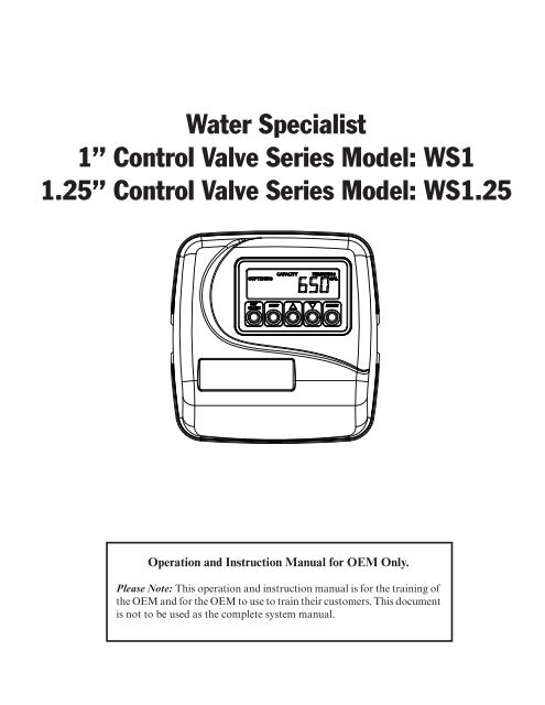
Water Specialist<br />
1” Control Valve Series Model: <strong>WS1</strong><br />
<strong>1.25</strong>” Control Valve Series Model: <strong>WS1</strong>.25<br />
Operation and Instruction Manual for OEM Only.<br />
Please Note: This operation and instruction <strong>manual</strong> is for the training of<br />
the OEM and for the OEM to use to train their customers. This document<br />
is not to be used as the complete system <strong>manual</strong>.
Table of Contents<br />
Control Valve Function and Cycles of Operation ....................................................................................................4<br />
OEM General Programming Instructions ................................................................................................................8<br />
OEM Softener System Setup .....................................................................................................................9<br />
OEM Filter System Setup ........................................................................................................................11<br />
Installer Displays/Settings .......................................................................................................................12<br />
User Displays/Settings .............................................................................................................................12<br />
Diagnostics ..............................................................................................................................................14<br />
Valve History ...........................................................................................................................................15<br />
Drawings and Part Numbers<br />
Front Cover and Drive Assembly ............................................................................................................16<br />
<strong>WS1</strong> Drive Cap, Pistons and Spacer Stack ..............................................................................................17<br />
<strong>WS1</strong>.25 Drive Cap, Pistons and Spacer Stacks .......................................................................................18<br />
FOR INFORMATION COMMON TO ALL 1” & <strong>1.25</strong>” CONTROL VALVES REFER TO THE<br />
<strong>WS1</strong> & <strong>WS1</strong>.25 DRAWINGS AND SERVICE MANUAL
Page 4 <strong>WS1</strong> & <strong>1.25</strong> Man u al<br />
Control Valve Function and Cycles of Operation<br />
This glass fi lled Noryl 1 (or equivalent) fully automatic control valve is designed as the primary control center to direct and<br />
regulate all cycles of a water softener or fi lter. When the <strong>WS1</strong> or the <strong>WS1</strong>.25 control valve is manufactured as a softener, the<br />
control valve can be ordered to perform downfl ow or upfl ow regeneration. When the <strong>WS1</strong> or <strong>WS1</strong>.25 control valve is set up<br />
as a fi lter, the control valve can be set to perform downfl ow regeneration or simply backwash. The control valve can be set<br />
to regenerate on demand (consumption of a predetermined amount of water) and/or as a time clock (passage of a particular<br />
number of days). The control valve can be set so that a softener can meet the Water Quality As so ci a tion (WQA) Standard<br />
S100 or NSF/ANSI Standard 44 effi ciency rating.<br />
It is not recommended to change control valves from downfl ow to upfl ow brining or vice versa in the fi eld. The valve bodies for<br />
downfl ow and upfl ow are unique to the regeneration type and and should not be interchanged. A mismatch of valve body and<br />
regeneration piston will result in hard water bypass during service.<br />
The control valve is compatible with a variety of regenerants and resin cleaners. The control valve is capable of routing the<br />
fl ow of water in the necessary paths to regenerate or backwash water treatment systems. The injector regulates the fl ow of<br />
brine or other regenerants. The control valve regulates the fl ow rates for backwashing, rinsing, and the replenishing of treated<br />
water into a regenerant tank, when applicable.<br />
The control valve uses no traditional fasteners (e.g. screws); instead clips, threaded caps and nuts and snap type latches are<br />
used. Caps and nuts only need to be fi rmly hand tightened because radial seals are used. Tools required to service the valve<br />
include one small blade screw driver, one large blade screw driver, pliers and a pair of hands. A plastic wrench is available<br />
which eliminates the need for screwdrivers and pliers. Disassembly for servicing takes much less time than com pa ra ble<br />
products currently on the market. Control valve in stal la tion is made easy because the distributor tube can be cut ½” above<br />
to ½” below the top of tank thread. The distributor tube is held in place by an o-ring seal and the control valve also has a<br />
bayonet lock feature for upper distributor baskets.<br />
The AC adapter power pack comes with a 15 foot power cord and is designed for use with the control valve. The AC adapter<br />
power pack is for dry location use only. The control valve remembers all settings for up to 8 hours if the power goes out and<br />
the battery is not depleted. After 8 hours, the only item that needs to be reset is the time of day; other values are permanently<br />
stored in the nonvolatile memory. If a power loss lasts less than 8 hours and the time fl ashes on and off, the time of day<br />
should be reset and the non rechargeable battery should be replaced.<br />
Table 1 shows the order of the cycles when the valve is set up as a softener. When the <strong>WS1</strong> or <strong>WS1</strong>.25 control valve is used<br />
as a downfl ow softener, two backwashes always occur. When the <strong>WS1</strong> or <strong>WS1</strong>.25 control valve is used as an upfl ow softener,<br />
only one backwash occurs after brining. The OEM has the option of having the regenerant refi ll after the rinse cycle or<br />
have the regenerant prefi ll before re gen er a tion. If the OEM chooses to have the regenerant prefi ll before regeneration, the<br />
prefi ll starts two hours before the re gen er a tion time set. During the 2-hour period in which the brine is being made, treated<br />
(softened) water is still available. For example: regeneration time = 2:00 am, prefi ll option selected, downfl ow softener. Fill<br />
occurs at 12:00 a.m., start of backwash cycle occurs at 2:00 a.m.<br />
When set up as a softener the backwash and rinse cycles automatically increase with increasing salt dosage. Backwashes can<br />
be set to be NORMAL or LONGER. The option selected will apply to all backwashes. Tables 2 and 3 show the length of the<br />
cycles when the valve is set up as a softener.<br />
<strong>WS1</strong> & <strong>WS1</strong>.25 Downfl ow<br />
Regenerant Refi ll After<br />
Rinse<br />
1st Cycle: Backwash<br />
2nd Cycle: Regenerate<br />
3rd Cycle: Backwash<br />
4th Cycle: Rinse<br />
5th Cycle: Fill/Dissolve<br />
6th Cycle: Service<br />
<strong>WS1</strong> & <strong>WS1</strong>.25 Downfl ow<br />
Regenerant Prefi ll<br />
1 st Cycle: Fill/Dissolve<br />
2 nd Cycle: Backwash<br />
3 rd Cycle: Regenerate<br />
4 th Cycle: Backwash<br />
5 th Cycle: Rinse<br />
6 th Cycle: Service<br />
Table 1<br />
Regeneration Cycles Softening<br />
1 Noryl is a trademark of Sabic Innovative Plastics IP B.V. Company<br />
<strong>WS1</strong> & <strong>WS1</strong>.25<br />
Upfl ow Regenerant<br />
Refi ll After Rinse<br />
1 st Cycle: Regenerate<br />
2 nd Cycle: Backwash<br />
3 rd Cycle: Rinse<br />
4 th Cycle: Fill/Dissolve<br />
5 th Cycle: Service<br />
<strong>WS1</strong> & <strong>WS1</strong>.25<br />
Upfl ow Regenerant<br />
Prefi ll<br />
1 st Cycle: Fill/Dissolve<br />
2 nd Cycle: Regenerate<br />
3 rd Cycle: Backwash<br />
4 th Cycle: Rinse<br />
5 th Cycle: Service
<strong>WS1</strong> & <strong>1.25</strong> Man u al Page 5<br />
Cycle time<br />
in Minutes<br />
Cycle time<br />
in Minutes<br />
Table 2<br />
Backwash Normal Length Softener<br />
Cycle Times in Minutes<br />
<strong>WS1</strong> & <strong>WS1</strong>.25 Downfl ow Softener <strong>WS1</strong> & <strong>WS1</strong>.25 Upfl ow Softener<br />
Grains Capacity/lb NaCl 6000 to 3501 3500 to 2501 2500 to 1700 6000 to 3501 3500 to 2501 2500 to 1700<br />
lbs NaCl/cu ft resin2 Less than 7.5 7.5 to 12 More than 12 Less than 7.5 7.5 to 12 More than 12<br />
Backwash Normal 6 8 8<br />
Regenerate 45 60 75 45 60 75<br />
Backwash Normal 3 8 10 6 10 12<br />
Rinse 3 4 6 3 4 6<br />
Total3 57 80 99 54 74 93<br />
Table 3<br />
Backwash Longer Length Softener<br />
Cycle Times in Minutes<br />
<strong>WS1</strong> & <strong>WS1</strong>.25 Downfl ow Softener <strong>WS1</strong> & <strong>WS1</strong>.25 Upfl ow Softener<br />
Grains Capacity/lb NaCl 6000 to 3501 3500 to 2501 2500 to 1700 6000 to 3501 3500 to 2501 2500 to 1700<br />
lbs NaCl/cu ft resin2 Less than 7.5 7.5 to 12 More than 12 Less than 7.5 7.5 to 12 More than 12<br />
Backwash Longer 8 10 12<br />
Regenerate 45 60 75 60 70 80<br />
Backwash Longer 8 10 12 12 14 16<br />
Rinse 4 6 8 5 7 9<br />
Total3 65 86 107 77 91 105<br />
Table 4 shows the order of the cycles when the valve is set up as a fi lter. When the control valve is used as a downfl ow<br />
re gen er at ing fi lter, the OEM has the option to specify one backwash or two backwashes. If the control valve is set to<br />
regenerate for a fi lter, the OEM has the option of having the regenerant refi ll after the rinse cycle or have the regenerant prefi ll<br />
before regeneration. If the OEM chooses to have the regenerant prefi ll before regeneration, the prefi ll starts two hours before<br />
the regeneration time set. During the 2-hour period in which the regenerant is being made, treated water is still available. For<br />
example: regeneration time = 2:00 am, prefi ll option selected, downfl ow fi lter. Fill occurs at 12:00 a.m., start of backwash<br />
cycle occurs at 2:00 a.m. There is only one rinse. Backwashes can be set to normal or longer. The option selected will apply to<br />
all backwashes. Tables 5 and 6 show the length of the cycles when the valve is set up as a fi lter.<br />
When the control valve is used as a non-regenerating fi lter, the OEM has the option to specify one backwash or two<br />
backwashes. If two backwashes are specifi ed, two rinses occur. Tables 5 and 6 show the length of the cycles when the valve<br />
is set up as a fi lter. When used as a non-regenerating fi lter, the downfl ow piston must be installed, the regenerant piston<br />
removed, injector plugs must be installed in both the DN and UP injector locations and the refi ll elbow must be replaced with<br />
a refi ll port plug.<br />
2 These are reference numbers that approximate the amount of salt needed. The actual capacity in grains per pound of salt is<br />
used in cal cu la tions.<br />
3 Total time does not include fi ll time, which is dependent upon the amount of salt needed. When in the fi ll mode the system<br />
is providing treated water.
Page 6 <strong>WS1</strong> & <strong>1.25</strong> Man u al<br />
<strong>WS1</strong> & <strong>WS1</strong>.25 Downfl ow<br />
Regenerant Refi ll After Rinse<br />
1st Cycle: Backwash<br />
2nd Cycle: Regenerate<br />
3rd Cycle: Second Backwash*<br />
4th Cycle: Rinse<br />
5th Cycle: Fill<br />
6th Cycle: Service<br />
Table 4<br />
Regeneration Cycles Filtering<br />
<strong>WS1</strong> & <strong>WS1</strong>.25 Downfl ow<br />
Regenerant Prefi ll<br />
1 st Cycle: Fill<br />
2 nd Cycle: Backwash<br />
3 rd Cycle: Regenerate<br />
4 th Cycle: Second Backwash*<br />
5 th Cycle: Rinse<br />
6 th Cycle: Service<br />
*Second backwash is optional<br />
**Second rinse only occurs if Second Backwash option is selected.<br />
Table 5<br />
Regenerating Filter<br />
Cycle Times in Minutes<br />
<strong>WS1</strong> & <strong>WS1</strong>.25<br />
No Regeneration<br />
1 st Cycle: Backwash<br />
2 nd Cycle: Rinse<br />
3 rd Cycle: Second Backwash*<br />
4 th Cycle: Second Rinse**<br />
5 th Cycle: Service<br />
<strong>WS1</strong> & <strong>WS1</strong>.25 Single Backwash <strong>WS1</strong> & <strong>WS1</strong>.25 Double Backwash<br />
Normal Longer Normal Longer<br />
Backwash 14 16 8 12<br />
Regenerate 60 60 60 60<br />
2nd Backwash 10 12<br />
Rinse 8 10 8 10<br />
Total4 82 86 86 94<br />
Table 6<br />
Non-Regenerating Filter<br />
Cycle Times in Minutes<br />
<strong>WS1</strong> & <strong>WS1</strong>.25 Single Backwash <strong>WS1</strong> & <strong>WS1</strong>.25 Double Backwash<br />
Normal Longer Normal Longer<br />
Backwash 14 16 8 12<br />
Rinse 8 10 6 6<br />
2nd Backwash 10 12<br />
2nd Rinse 8 10<br />
Total 22 26 32 40<br />
The control valve with a water meter can be set for Demand Initiated Regeneration (DIR) only, Time Clock operation only<br />
or DIR and Time Clock which ever comes fi rst, depending upon what settings are selected for Day Override and Gallon<br />
Capacity. 5 See Table 7.<br />
If a control valve does not contain a meter, the valve can only act as a time clock, and day override should be set to any<br />
number and gallon capacity should be set to off.<br />
4 Total time does not include fi ll time, which is dependent upon the amount of fi ll needed. When in the fi ll mode the system is<br />
providing treated water.<br />
5 See Installer Display Settings Step 3I, OEM Softener Setup Step 6S and OEM Filter Setup Step 5F for ex pla na tions of Day<br />
Over ride and Gallon Capacity.
<strong>WS1</strong> & <strong>1.25</strong> Man u al Page 7<br />
DIR<br />
Time<br />
Clock<br />
Reserve Capacity Softener<br />
Table 7<br />
DIR/Time Clock Options<br />
Regenerant<br />
For DIR Softeners, there are two options for setting the Gallons Capacity. The Gallons Capacity is automatically calculated if<br />
set to AUTO. Reserve Capacity is automatically estimated based on water usage if AUTO is used. The other option is to set the<br />
Gallons Capacity to a specifi c number. If a specifi c number is set, reserve capacity is zero, unless the value is <strong>manual</strong>ly set (i.e. the<br />
man u fac tur er intentionally sets the gallon capacity number below the calculated capacity of the system).<br />
The <strong>WS1</strong> & <strong>WS1</strong>.25 control valves can also be set to regenerate immediately or at the next regeneration time by changing the<br />
Regeneration Time Option. There are three choices for settings:<br />
1. “NORMAL” means regeneration will occur at the preset regeneration time.<br />
2. “on 0” means regeneration will occur when the gallons capacity reaches zero.<br />
3. “NORMAL” and “on 0” means the regeneration will occur at the preset regeneration time unless the gallons capacity reaches<br />
zero. If the gallons capacity reaches zero the regeneration will begin 10 minutes after no water usage.<br />
The user can initiate <strong>manual</strong> regeneration. The user has the option to request the <strong>manual</strong> regeneration at the delayed regeneration<br />
time or to have the regeneration occur immediately:<br />
1. Pressing and releasing the REGEN button. “Regen Today” will fl ash on the display and the regeneration will occur at the<br />
delayed re gen er a tion time. The user can cancel the request by pressing and releasing the REGEN button. This method of<br />
<strong>manual</strong>ly initiating regeneration is not allowed when the system is set to “on 0”, i.e. to immediately regenerate when the gallon<br />
capacity reaches zero.<br />
2. Pressing and holding the REGEN button for approximately 3 seconds will immediately start the regeneration. The user cannot<br />
cancel this request, except by resetting the control by pressing NEXT and REGEN buttons simultaneously for 3 seconds.<br />
A unique feature of this control valve is the ability to display actual water usage for the last 63 days. The values are initially stored as<br />
“----”. This means the value is unknown. As days pass values are stored as “0” for no fl ow or the actual number of gallons. The<br />
counting of the gallons starts at the regeneration time. If no regeneration time can be set (i.e. when the valve is set for immediate<br />
regeneration) the counting of gallons starts at 12 a.m. Day 1 is yesterday, day 2 the day before yesterday, etc. As new values are<br />
added the oldest history disappears.<br />
Another unique feature is that the valve automatically calculates a reserve capacity when set up as a softener with “Gallons<br />
Ca pac i ty” set to “AUTO” and the “Regeneration Time Option” set to “Normal” or “Normal + on 0”. The actual reserve capacity<br />
is com pared to the gallons capacity remaining immediately prior to the preset regeneration time. A regeneration will occur if the<br />
actual reserve capacity is less than the gallons capacity remaining. The actual reserve capacity is calculated by using the estimated<br />
reserve capacity and adjusting it up or down for actual usage.<br />
The estimated reserve capacity for a given day of the week is the maximum value stored for the last three non-trivial water usages<br />
(i.e. more than 20 gallons/day) in seven day intervals.<br />
6 Day Override and Gallon Capacity can not both be set to “oFF” at the same time.<br />
Filter Settings 6<br />
Backwash<br />
Only<br />
Day<br />
Override<br />
Gallon<br />
Capacity<br />
Yes Automatically Calculated Yes Off Auto<br />
Yes<br />
If desired enter a value less<br />
than estimated capacity<br />
Yes Yes Automatically Calculated Yes<br />
Yes Yes<br />
If desired enter a value less<br />
than estimated capacity<br />
Yes Yes Yes Off<br />
Yes Yes Yes<br />
Yes None Yes Yes Yes<br />
Any<br />
Number<br />
Any<br />
Number<br />
Any<br />
Number<br />
Any<br />
Number<br />
Auto<br />
Any<br />
Number<br />
Off
Page 8 <strong>WS1</strong> & <strong>1.25</strong> Man u al<br />
OEM General In struc tions<br />
The control valve offers multiple procedures that allow the valve to be modifi ed to suit the needs of the installation. These<br />
pro ce dures are:<br />
OEM Softener Setup<br />
OEM Filter Setup<br />
Installer Displays & Settings<br />
User Displays & Settings<br />
Diagnostics<br />
Valve History<br />
These procedures can be accessed in any order. Details on each of the procedures are provided on the following pages.<br />
At the discretion of the manufacturer, the fi eld technician can access all settings. To “lock out” access to diagnostic and valve<br />
history displays and modifi cations to settings except hardness, day override, time of regeneration and time of day by anyone<br />
but the manufacturer, press ▼, NEXT, ▲, and SET CLOCK in sequence after settings are made. To “unlock”, so other<br />
displays can be viewed and changes can be made, press ▼, NEXT, ▲, and SET CLOCK in sequence.<br />
When in operation normal user displays such as time of day, gallons remaining or days remaining before regeneration are<br />
shown. When stepping through a procedure, if no buttons are pressed within fi ve minutes the display returns to a normal user<br />
display. Any changes made prior to the fi ve minute time out are incorporated. The one exception is current fl ow rate display<br />
under the di ag nos tic procedure. The current fl ow rate display has a 30 minute time out feature.<br />
To quickly exit OEM Softener Setup, OEM Filter Setup, Installer Display Settings, Diagnostics or Valve History press SET<br />
CLOCK. Any changes made prior to the exit are incorporated.<br />
When desired all information in Diagnostics may be reset to zero when the valve is moved to a new location. To reset to zero,<br />
press NEXT and ▼ buttons simultaneously to go to the Service/OEM 1 screen, and release. Press ▲ and ▼ simultaneously to<br />
reset diagnostic values to zero. Screen will return to User Display.<br />
Sometimes it is desirable to have the valve initiate and complete two regenerations within 24 hours and then return to<br />
the preset regeneration procedure. It is possible to do a double regeneration if the control valve is set to “NORMAL” or<br />
“NORMAL + on 0” in Step 9S or Step 7F. To do a double regeneration:<br />
1. Press the “REGEN” button once. REGEN TODAY will fl ash on the display.<br />
2. Press and hold the “REGEN” button for three seconds until the valve regeneration initiates.<br />
Once the valve has completed the immediate regeneration, the valve will regenerate one more time at the preset regeneration<br />
time.
<strong>WS1</strong> & <strong>1.25</strong> Man u al Page 9<br />
RETURN TO<br />
NORMAL MODE<br />
STEP 1S<br />
STEP 2S<br />
STEP 3S<br />
STEP 4S<br />
STEP 5S<br />
STEP 6S<br />
STEP 7S<br />
STEP 8S<br />
STEP 9S<br />
OEM Softener System Setup Quick Reference<br />
This is a quick reference setup procedure. See OEM Softener System Setup Detail for<br />
more information on available settings.<br />
STEP 1S – Press NEXT and ▼ buttons simultaneously for 3 seconds. If screen in step<br />
2S does not appear in 5 seconds the lock on the valve is activated. To unlock press ▼,<br />
NEXT, ▲, and SET CLOCK in se quence, then press NEXT and ▼ si mul ta neous ly for<br />
3 seconds.<br />
STEP 2S – Choose Softening using ▼ or ▲ buttons. Press NEXT to go to Step 3S.<br />
Press REGEN to exit OEM Softener System Setup.<br />
STEP 3S – Enter the ion exchange capacity in grains of hardness as calcium carbonate<br />
for the system based on test data using ▼ or ▲ buttons. Press NEXT to go to Step 4S.<br />
Press REGEN to return to previous step.<br />
STEP 4S – Enter the pounds of salt per regeneration using ▼ or ▲ buttons. Press<br />
NEXT to go to Step 5S. Press REGEN to return to previous step.<br />
STEP 5S – Backwash: Select “NORMAL” or “LONGER” using ▼ or ▲ buttons.<br />
See Tables 2 or 3 for backwash times. Press NEXT to go to Step 6S. Press REGEN to<br />
return to previous step.<br />
STEP 6S – Set Gallons Capacity using ▼ or ▲ buttons:<br />
• “AUTO” (reserve capacity automatically estimated and gallons capacity<br />
au to mat i cal ly calculated from grains capacity and water hardness);<br />
• “oFF” (regeneration based on day override); or<br />
• number of gallons (20 to 50,000).<br />
See Setting Options Table for more detail. Press NEXT to go to Step 7S. Press REGEN<br />
to return to previous step.<br />
STEP 7S – Set Refi ll option using ▼ or ▲ buttons:<br />
• “PoST” to refi ll the brine tank after the fi nal rinse; or<br />
• “PrE” to refi ll the brine tank two hours before the regeneration time set.<br />
Press NEXT to go to Step 8S. Press REGEN to return to previous step.<br />
STEP 8S – Set regenerant downfl ow or upfl ow using ▼ or ▲ buttons:<br />
• “dn” if the regenerant is to fl ow downward through the media; or<br />
• “UP” if the regenerant is to fl ow upward through the media.<br />
Prior to selecting a regenerant fl ow direction, verify the correct valve body, main piston,<br />
regenerant piston, and stack are being used, and that the injector or injector plug(s) are in<br />
the correct locations. See Valve Body Compliance Table in <strong>WS1</strong> & <strong>WS1</strong>.25 Drawings and<br />
Service Manual.<br />
Press NEXT to go to Step 9S. Press REGEN to return to previous step.<br />
STEP 9S – Set Regeneration Time Option using ▼ or ▲ buttons:<br />
• “NORMAL” means regeneration will occur at the preset time;<br />
• “on 0” means regeneration will occur immediately when the gallons capacity<br />
reaches 0 (zero); or<br />
• “NORMAL + on 0” means regeneration will occur at one of the following:<br />
• the preset time when the gallons capacity falls below the reserve or the<br />
spec i fi ed number of days between regenerations is reached which ev er comes<br />
fi rst; or<br />
• after 10 minutes of no water usage when the gallon capacity reaches 0 (zero).<br />
See Setting Options Table for more detail. Press NEXT to exit OEM Softener System<br />
Setup. Press REGEN to return to previous step.
Page 10 <strong>WS1</strong> & <strong>1.25</strong> Man u al<br />
Volume<br />
Capacity<br />
Regeneration<br />
Time Option<br />
Day<br />
Override<br />
AUTO NORMAL oFF<br />
AUTO NORMAL<br />
Any<br />
number<br />
oFF NORMAL<br />
Any<br />
number<br />
Any<br />
number<br />
NORMAL oFF<br />
NORMAL<br />
Any<br />
number<br />
Any<br />
number<br />
AUTO On O oFF<br />
Any<br />
number<br />
On O oFF<br />
AUTO NORMAL on 0 oFF<br />
AUTO NORMAL on 0<br />
Any<br />
number<br />
NORMAL on 0<br />
Any<br />
number<br />
Any<br />
number<br />
7 Reserve capacity estimate is based on history of water usage.<br />
Setting Options Table<br />
Filters should only use shaded options.<br />
Result 7<br />
Reserve capacity automatically estimated.<br />
Regeneration occurs when volume capacity falls below the reserve<br />
capacity at the next Regen Set Time<br />
Reserve capacity automatically estimated.<br />
Regeneration occurs at the next Regen Set Time when volume capacity<br />
falls below the reserve capacity or the specifi ed number of days between<br />
regenerations is reached.<br />
Reserve capacity not automatically estimated.<br />
Regeneration occurs at the next Regen Set Time when volume<br />
capacity reaches 0.<br />
Reserve capacity not automatically estimated.<br />
Regeneration occurs at the next Regen Set Time when the specifi ed<br />
number of days between regenerations is reached.<br />
Reserve capacity not automatically estimated.<br />
Regeneration occurs at the next Regen Set Time when volume<br />
capacity reaches 0 or the specifi ed number of days between<br />
regenerations is reached.<br />
Reserve capacity not automatically estimated.<br />
Regeneration occurs immediately when volume capacity reaches 0.<br />
Time of regeneration will not be allowed to be set because regeneration<br />
will always occur when volume capacity reaches 0.<br />
Reserve capacity not automatically estimated.<br />
Regeneration occurs immediately when volume capacity reaches 0.<br />
Time of regeneration will not be allowed to be set because regeneration<br />
will always occur on 0.<br />
Reserve capacity automatically estimated.<br />
Regeneration occurs when volume capacity falls below the reserve<br />
capacity at the next Regen Set Time or regeneration occurs after 10<br />
minutes of no water usage when volume capacity reaches 0.<br />
Reserve capacity automatically estimated.<br />
Regeneration occurs at the next Regen Set Time when volume capacity<br />
falls below the reserve capacity or the specifi ed number of days between<br />
regenerations is reached or regeneration occurs after 10 minutes of no<br />
water usage when volume capacity reaches 0.<br />
Reserve capacity not automatically estimated.<br />
Regeneration occurs at the next Regen Set Time when the specifi ed<br />
number of days between regenerations is reached or regeneration occurs<br />
after 10 minutes of no water usage when volume capacity reaches 0.
<strong>WS1</strong> & <strong>1.25</strong> Man u al Page 11<br />
RETURN TO<br />
NORMAL MODE<br />
STEP 1F<br />
STEP 2F<br />
STEP 3F<br />
STEP 4F<br />
STEP 5F<br />
STEP 6F<br />
STEP 7F<br />
OEM Filter System Setup Quick Reference<br />
This is a quick reference setup procedure. See OEM Filter System Setup Detail for<br />
more information on available settings.<br />
STEP 1F – Press NEXT and ▼ simultaneously for 3 seconds. If screen in step 2F does<br />
not appear in 5 seconds the lock on the valve is activated. To unlock press ▼, NEXT,<br />
▲, and SET CLOCK in sequence, then press NEXT and ▼ simultaneously for 3<br />
seconds.<br />
STEP 2F – Choose Filtering using ▼ or ▲ buttons. Press NEXT to go to step 3F. Press<br />
REGEN to exit OEM Filter System Setup.<br />
STEP 3F – Enter “oFF” if regenerant is not used (i.e. backwash only) or enter the refi ll<br />
volume (in gallons) using ▼ or ▲ buttons. Prior to selecting oFF or regenerant volume,<br />
verify the correct valve body, main piston, regenerant piston, and stack are being used,<br />
and that the injector or injector plug(s) are in the correct locations. See Compliance Table<br />
in Service Instructions under Injector Cap, Screen, Injector Plug and Injector section and<br />
Figure 6. Press NEXT to go to step 4F. Press REGEN to return to previous step.<br />
STEP 4F – Backwash: Select using ▼ or ▲ buttons:<br />
• “NORMAL” for one “NORMAL” backwash (14 minutes);<br />
• “NORMAL 2” for two “NORMAL” backwashes (8 minutes each);<br />
• “LONGER” for one “LONGER” backwash (16 minutes); or<br />
• “LONGER 2” for two “LONGER” backwashes (12 minutes each).<br />
See Tables 5 and 6 for additional details. Press NEXT to go to step 5F. Press REGEN<br />
to return to previous step.<br />
STEP 5F – Set Gallons Capacity using ▼ or ▲ buttons:<br />
• “oFF” (regeneration based on day override); or<br />
• number of gallons (20 to 50,100).<br />
See Setting Options Table for more detail. Press NEXT to go to step 6F. Press REGEN<br />
to return to previous step.<br />
STEP 6F – Set Refi ll option using ▼ or ▲ buttons:<br />
• “PoST” to refi ll the brine tank after the fi nal rinse; or<br />
• “PrE” to refi ll the brine tank two hours before the re gen er a tion time set.<br />
Press NEXT to go to step 7F. Press REGEN to return to previous step.<br />
STEP 7F – Set Regeneration Time Option using ▼ or ▲ buttons:<br />
• “NORMAL” means regeneration will occur at the preset time;<br />
• “on 0” means regeneration will occur immediately when the gallons capacity<br />
reaches 0 (zero); or<br />
• “NORMAL + on 0” means regeneration will occur at one of the following:<br />
• the preset time when the specifi ed number of days between regenerations is<br />
reached; or<br />
• after 10 minutes of no water usage when the gallon capacity reaches 0 (zero).<br />
See Setting Options Table for more detail. Press NEXT to exit OEM Filter System<br />
Setup. Press REGEN to return to previous step.
Page 12 <strong>WS1</strong> & <strong>1.25</strong> Man u al<br />
RETURN TO<br />
NORMAL MODE<br />
General Operation<br />
STEP 1I<br />
STEP 2I<br />
STEP 3I<br />
STEP 4I<br />
STEP 5I<br />
When the system is operating one of two displays will<br />
be shown. Press ing NEXT will alternate between the<br />
dis plays. One of the displays is always the current time<br />
of day. The second display is one of the fol low ing: days<br />
remaining or gallons remaining. Days remaining is the<br />
number of days left before the system goes through a<br />
regeneration cycle. Ca pac i ty remaining is the number<br />
of gallons that will be treated before the system goes<br />
through a regeneration cycle. The user can scroll<br />
between the displays as desired.<br />
If the system has called for a regeneration that will<br />
occur at the preset time of re gen er a tion, the words<br />
REGEN TODAY will appear on the display.<br />
When water is being treated (i.e. water is fl owing<br />
through the system) the word “Soft en ing” or<br />
“Fil ter ing” fl ashes on the display if a water meter is<br />
installed.<br />
Installer Display Settings<br />
STEP 1I - Press NEXT and ▲ simultaneously for 3 seconds.<br />
STEP 2I – Hardness: Set the amount of hardness in grains of hardness as calcium<br />
car bon ate per gallon using the ▼ or ▲ buttons. The default is 20 with value ranges<br />
from 1 to 150 in 1 grain increments. Note: The grains per gallon can be in creased<br />
if soluble iron needs to be reduced. This display will show “–nA–” if “FILTER” is<br />
selected in Step 2F or if ‘AUTO’ is not selected in Step 6S. Press NEXT to go to step<br />
3I. Press REGEN to exit Installer Dis play Settings.<br />
STEP 3I – Day Override: When gallon capacity is set to off, Day Override sets the<br />
number of days between re gen er a tions. When gallon capacity is set to AUTO or to<br />
a number, Day Override sets the max i mum number of days between re gen er a tions.<br />
If value set to “oFF” re gen er a tion initiation is based solely on gallons used. If value<br />
is set as a number (allowable range from 1 to 28) a re gen er a tion initiation will be<br />
called for on that day even if suffi cient number of gallons were not used to call for a<br />
regeneration. Set Day Override using ▼ or ▲ buttons:<br />
• number of days between regeneration (1 to 28); or<br />
• “oFF”.<br />
See Setting Options Table for more detail on setup. Press NEXT to go to step 4I. Press<br />
REGEN to return to previous step.<br />
STEP 4I – Next Regeneration Time (hour): Set the hour of day for regeneration using<br />
▼ or ▲ buttons. AM/PM toggles after 12. The default time is 2:00 a.m. This display<br />
will show “REGEN on 0 GAL” if “on 0” is selected in Step 9S or Step 7F. Press<br />
NEXT to go to step 5I. Press REGEN to return to previous step.<br />
STEP 5I – Next Regeneration Time (minutes): Set the minutes of day for regeneration<br />
using ▼ or ▲ buttons. This display will not be shown if “on 0” is selected in Step 9S<br />
or Step 7F. Press NEXT to exit Installer Display Settings. Press REGEN to return to<br />
previous step.<br />
To initiate a <strong>manual</strong> regeneration immediately, press and hold the “REGEN” button<br />
for three seconds. The system will begin to re gen er ate im me di ate ly. The control valve<br />
may be stepped through the various re gen er a tion cycles by pressing the “REGEN”<br />
button.<br />
User Display Settings<br />
REGEN TODAY will be<br />
displayed if a regeneration<br />
is expected “Tonight.”<br />
OR
<strong>WS1</strong> & <strong>1.25</strong> Man u al Page 13<br />
Regeneration Mode<br />
Typically a system is set to regenerate at a time of low water usage. An example of a time<br />
with low water usage is when a household is asleep. If there is a demand for water when<br />
the system is regenerating, untreated water will be used.<br />
When the system begins to regenerate, the display will change to include information<br />
about the step of the regeneration process and the time remaining for that step to be completed. The system runs through the<br />
steps au to mat i cal ly and will reset itself to provide treated water when the regeneration has been completed.<br />
Manual Regeneration<br />
Sometimes there is a need to regenerate the system sooner<br />
than when the system calls for it, usually referred to as <strong>manual</strong><br />
re gen er a tion. There may be a period of heavy water usage<br />
because of guests or a heavy laundry day.<br />
To initiate a <strong>manual</strong> regeneration at the preset delayed<br />
regeneration time, when the regeneration time option is set to “NORMAL” or “NORMAL<br />
+ on 0”, press and release “REGEN”. The words “REGEN TO DAY” will fl ash on the<br />
display to indicate that the system will re gen er ate at the preset delayed re gen er a tion time. If<br />
you pressed the “REGEN” button in error, pressing the button again will cancel the request. Note: If the regeneration time<br />
option is set to “on 0” there is no set delayed regeneration time so “REGEN TODAY” will not activate if “REGEN” button<br />
is pressed.<br />
To initiate a <strong>manual</strong> regeneration immediately, press and hold the “REGEN” button for three seconds. The system will begin<br />
to regenerate immediately. The request cannot be cancelled.<br />
Note: For softeners, if brine tank does not contain salt, fi ll with salt and wait at least two hours before regenerating.<br />
STEP 1U Set Time of Day<br />
The user can also set the time of day. Time of day should only need to be set after power<br />
outages lasting more than 8 hours, if the battery has been depleted and a power outage<br />
STEP 2U occurs, or when daylight saving time begins or ends. If a power outage lasting more than<br />
8 hours occurs, the time of day will fl ash on and off which indicates the time of day<br />
should be reset. If a power outage lasts less than 8 hours and the time of day fl ashes on<br />
and off, the time of day should be reset and the battery replaced.<br />
STEP 3U<br />
STEP 1U – Press SET CLOCK.<br />
REGEN TODAY will<br />
Flash if a regeneration<br />
is expected “Tonight.”<br />
STEP 2U - Current Time (hour): Set the hour of the day using ▼ or ▲ buttons. AM/<br />
PM toggles after 12. Press NEXT to go to step 3U.<br />
STEP 3U - Current Time (minutes): Set the minutes of the day using ▼ or ▲ buttons.<br />
Press NEXT to exit Set Clock. Press REGEN to return to previous step.<br />
Power Loss<br />
If the power goes out, the system will keep time for up to 8 hours or until the battery is depleted. If a power outage of more<br />
than 8 hours occurs, the time of day will fl ash on and off which indicates the time of day should be reset. The system will<br />
remember the rest. If a power outage lasts less than 8 hours and the time of day fl ashes on and off, the non rechargeable<br />
battery should be replaced.<br />
Error Message<br />
If the word “ERROR” and a number are alternately fl ashing on the display<br />
contact the OEM for help. This indicates that the valve was not able to function<br />
properly.
Page 14 <strong>WS1</strong> & <strong>1.25</strong> Man u al<br />
RETURN TO<br />
NORMAL MODE<br />
STEP 1D<br />
STEP 2D<br />
STEP 3D<br />
STEP 4D<br />
STEP 5D<br />
STEP 6D<br />
STEP 7D<br />
STEP 8D<br />
STEP 9D<br />
STEP 10D<br />
Diagnostics<br />
STEP 1D – Press ▼ or ▲ simultaneously for three seconds. If screen in step 2D does not<br />
appear in 5 seconds the lock on the valve is activated. To unlock press ▼, NEXT, ▲, and<br />
SET CLOCK in sequence, then press NEXT and ▼ simultaneously for 3 seconds.<br />
STEP 2D – Days, since last regeneration: This display shows the days since the last<br />
re gen er a tion occurred. Press the NEXT button to go to Step 3D. Press REGEN to exit<br />
Diagnostics.<br />
STEP 3D – Gallons, since last regeneration: This display shows the number of gallons that<br />
have been treated since the last re gen er a tion. This display will equal zero if a water meter is<br />
not installed. Press the NEXT button to go to Step 4D. Press REGEN to return to previous<br />
step.<br />
STEP 4D – Gallons, reserve capacity used for last 7 days: If the valve is set up as a softener, a<br />
meter is installed and Set Gallons Capacity is set to “Auto,” this display shows 0 day (for<br />
today) and fl ashes the reserve capacity. Press ing the<br />
▲ button will show day 1 (which would be yesterday)<br />
and fl ashes the reserve capacity used. Press ing the<br />
▲ button again will show day 2 (the day before<br />
yesterday) and the reserve capacity. Keep pressing the<br />
▲ button to show the gallons for days 3, 4, 5 and 6.<br />
The ▼ button can be pressed to move back wards in<br />
the day series. Press the NEXT button at any time to<br />
go to Step 5D. Press REGEN to return to previous<br />
step.<br />
STEP 5D - Gallons, 63 day usage history: This display<br />
shows day 1 (for yesterday) and fl ashes the number<br />
of gallons treated yesterday. Pressing the ▲ button will show day 2 (which would be the day<br />
before yesterday) and fl ashes the number of gallons treated on that day. Con tin ue to press the<br />
▲ button to show the max i mum number of gallons treated for the last 63 days. This display<br />
will show dashes if a water meter is not installed. Press the NEXT button at any time to go<br />
to Step 6D. Press REGEN to return to previous step.<br />
STEP 6D – Flow rate, current: Turn the water on at one or more taps in the building. The<br />
fl ow rate in gallons per minute will be displayed. If fl ow stops the value will fall to zero in a<br />
few seconds. This display will equal zero if a water meter is not installed. Press the NEXT<br />
button to go to Step 7D. Press REGEN to return to previous step.<br />
STEP 7D – Flow rate, maximum last seven days: The maximum fl ow rate in gallons per<br />
minute that occurred in the last seven days will be displayed. This display will equal zero if<br />
a water meter is not installed. Press the NEXT button to go to Step 8D. Press REGEN to<br />
return to previous step.<br />
STEP 8D – Gallons, total used since last reset: The total number of gallons used since last<br />
reset will be displayed. This display will equal zero if a water meter is not installed. Press the<br />
NEXT button to go to Step 9D. Press REGEN to return to previous step.<br />
STEP 9D – Days, total number since last reset: The total number of days the control valve<br />
has been in service since last reset will be displayed. Press the NEXT button to go to Step<br />
10D. Press REGEN to return to previous step.<br />
STEP 10D – Regenerations, total number since last reset: The total number of re gen er a tions<br />
that have occurred since last reset will be displayed. Press the NEXT button to exit<br />
Di ag nos tics. Press REGEN to return to previous step.<br />
When desired, all information in Diagnostics may be reset to zero when the valve is installed<br />
in a new location. To reset to zero, press NEXT and ▼ buttons simultaneously to go to the<br />
Service/OEM screen, and release. Press ▼ and ▲ simultaneously to reset diagnostic values to<br />
zero. Screen will return to user display.
<strong>WS1</strong> & <strong>1.25</strong> Man u al Page 15<br />
RETURN TO<br />
NORMAL MODE<br />
STEP 1VH<br />
STEP 1VH<br />
STEP 2VH<br />
STEP 3VH<br />
STEP 4VH<br />
STEP 5VH<br />
STEP 6VH<br />
STEP 7VH<br />
8 Values in steps 3VH through 7VH cannot be reset.<br />
Valve History<br />
STEP 1VH – Press ▲ and ▼ simultaneously for three seconds and release. Then<br />
press ▲ and ▼ si mul ta neous ly and release. If screen in step 2VH does not appear<br />
in 5 seconds the lock on the valve is activated. To unlock press ▼, NEXT, ▲, and<br />
SET CLOCK in sequence, then press ▲ and ▼ si mul ta neous ly for 3 seconds and<br />
release. Then press ▲ and ▼ simultaneously and release.<br />
STEP 2VH – Software Version: This display shows the software version of the<br />
valve. Press the NEXT button to go to Step 3VH. Press REGEN to exit Valve<br />
History.<br />
STEP 3VH 8 – Flow rate, maximum since startup: This display shows the<br />
max i mum fl ow rate in gallons per minute that has oc curred since startup. This<br />
display will equal zero if a water meter is not installed. Press the NEXT button to<br />
go to Step 4VH. Press REGEN to return to previous step.<br />
STEP 4VH – Gallons, total used since start-up: This display shows the total<br />
gallons treated since startup. This display will equal zero if a water meter is not<br />
in stalled. Press the NEXT button to go to Step 5VH. Press REGEN to return to<br />
previous step.<br />
STEP 5VH – Days, total since start-up: This display shows the total days since<br />
startup. Press the NEXT button to go to Step 6VH. Press REGEN to return to<br />
previous step.<br />
STEP 6VH – Regenerations, total number since start-up: This display shows the<br />
total number of regenerations that have occurred since startup. Press the NEXT<br />
button to go to Step 7VH. Press REGEN to return to previous step.<br />
STEP 7VH – Error Log: This display shows a history of the last 10 errors<br />
generated by the control during operation. Press the ▲ or ▼ buttons to review<br />
each error recorded. Press the NEXT button to exit Valve History. Press REGEN<br />
to return to previous step.
Page 16 <strong>WS1</strong> & <strong>1.25</strong> Man u al<br />
Front Cover and Drive Assembly<br />
Drawing No. Order No. Description Quantity<br />
1 V3175-01 <strong>WS1</strong> Front Cover ASY 1<br />
2 V3107-01 <strong>WS1</strong> Motor 1<br />
3 V3106-01 <strong>WS1</strong> Drive Bracket&Spring Clip 1<br />
4 V3108-09BOARD <strong>WS1</strong> PC Board with Battery REPLACE 1<br />
5 V3110 <strong>WS1</strong> Drive Reducing Gear 12x36 3<br />
6 V3109 <strong>WS1</strong> Drive Gear Cover 1<br />
V3002 <strong>WS1</strong> Drive ASY *<br />
Not Shown V3186 <strong>WS1</strong> AC Adapter 110V-12V 1<br />
Not Shown<br />
V3186 <strong>WS1</strong> AC ADAPTER 110V-12V<br />
V3186EU <strong>WS1</strong> AC ADAPTER 220-240V-12V EU<br />
V3186UK <strong>WS1</strong> AC ADAPTER 220-240V-12V UK<br />
V3186-01 <strong>WS1</strong> AC ADAPTER CORD ONLY<br />
* Drawing number parts 2 through 6 may be purchased as a complete assembly, part V3002.<br />
AC Adapter U.S. International<br />
Supply Voltage 120 V AC 230V AC<br />
Supply Frequency 60 Hz 50 Hz<br />
Output Voltage 12 V AC 12 V AC<br />
Output Current 500 mA 500 mA<br />
<br />
When replacing the battery, align<br />
positives and push down to fully seat.<br />
<br />
Battery Fully Seated<br />
Correct<br />
Battery<br />
Orientation<br />
<br />
<br />
<br />
1<br />
Battery replacement is<br />
3 volt lithium coin cell<br />
type 2032.
<strong>WS1</strong> & <strong>1.25</strong> Man u al Page 17<br />
2<br />
<strong>WS1</strong> Drive Cap Assembly, Downfl ow Piston, Upfl ow Piston, Regenerant Piston and Spacer Stack Assembly<br />
Drawing No. Order No. Description Quantity<br />
1 V3005 <strong>WS1</strong> Spacer Stack Assembly 1<br />
2 V3004 Drive Cap ASY 1<br />
3 V3178 <strong>WS1</strong> Drive Back Plate 1<br />
4a<br />
4b<br />
V3011*<br />
V3011-01*<br />
<strong>WS1</strong> Piston Downfl ow ASY<br />
<strong>WS1</strong> Piston Upfl ow ASY<br />
1<br />
5 V3174 <strong>WS1</strong> Regenerant Piston 1<br />
6 V3135 O-ring 228 1<br />
7 V3180 O-ring 337 1<br />
8 V3105 O-ring 215 (Distributor Tube) 1<br />
V3001 <strong>WS1</strong> Body ASY Downfl ow<br />
Not Shown<br />
V3001-02<br />
V3001UP<br />
<strong>WS1</strong> Mixing Valve Body ASY<br />
<strong>WS1</strong> Body ASY Upfl ow<br />
V3001-02UP <strong>WS1</strong> Mixing Valve Body Upfl ow ASY<br />
*V3011 is labeled with DN and V3011-01 is labeled with UP.<br />
Note: The regenerant piston is not used in backwash only applications.<br />
4b<br />
6<br />
4a<br />
1<br />
5<br />
3<br />
1<br />
Black Plug<br />
8<br />
7
Page 18 <strong>WS1</strong> & <strong>1.25</strong> Man u al<br />
<strong>WS1</strong>.25 Drive Cap Assembly, Downfl ow Piston, Upfl ow Piston, Regenerant Piston and Spacer Stack Assemblies<br />
Drawing No. Order No. Description Quantity<br />
1a<br />
1b<br />
V3430<br />
V3005<br />
<strong>WS1</strong>.5 Spacer Stack Assembly<br />
<strong>WS1</strong> Spacer Stack Assembly<br />
1<br />
2 V3004 Drive Cap Assembly 1<br />
3 V3178 Ws1 Drive Back Plate 1<br />
4a<br />
4b<br />
V3407<br />
V3011-01<br />
<strong>WS1</strong>.5 Piston Downfl ow Assembly<br />
<strong>WS1</strong> Piston Upfl ow Assembly<br />
1<br />
5 V3174 <strong>WS1</strong> Regenerant Piston 1<br />
6 V3135 O-ring 228 1<br />
7 V3180 O-ring 337 1<br />
8<br />
Not Shown<br />
V3358 O-ring 219 (Distributor tube opening 1.32”)<br />
V3357 O-ring 218 (Distributor tube opening 32mm)<br />
V3020 <strong>WS1</strong>.25 Body Assembly Downfl ow (Distributor tube opening 1.32”)<br />
V3020-01 <strong>WS1</strong>.25 Mixing Valve Body Downfl ow Asy (Distributor tube opening 1.32”)<br />
V3020-02 <strong>WS1</strong>.25 Body Assembly Downfl ow (Distributor tube opening 32mm)<br />
V3020-03 <strong>WS1</strong>.25 Mixing Valve Body Downfl ow Asy (Distributor tube opening 32mm)<br />
V3020UP <strong>WS1</strong>.25 Body Assembly Upfl ow (Distributor tube opening 1.32”)<br />
V3020-02UP <strong>WS1</strong>.25 Body Assembly Upfl ow (Distributor tube opening 32mm)<br />
Note: The regenerant piston is not used in backwash only applications.<br />
1<br />
1<br />
Grey Plug on all<br />
<strong>WS1</strong>.25 bodies<br />
*Grey Ring<br />
*Grey Distributor<br />
O-ring retainer<br />
*Only for valves that have a<br />
32mm Distributor Tube Opening
<strong>WS1</strong> & <strong>1.25</strong> Man u al Page 19<br />
Grey Plug<br />
Grey Ring<br />
Grey Plug<br />
Grey Distributor O-ring Retainer<br />
<strong>WS1</strong> & <strong>WS1</strong>.25 Identifi cation Figure<br />
<strong>WS1</strong> with 1.050" Distributor Tube Opening Identifi cation<br />
Black Plug<br />
<strong>WS1</strong>.25 with 1.32" Distributor Tube Opening Identifi cation<br />
Down fl ow and Backwash<br />
Upfl ow<br />
1.5"<br />
<br />
<br />
Spacer Color:<br />
Grey<br />
<strong>1.25</strong>"<br />
<strong>1.25</strong>"<br />
Note: The <strong>WS1</strong> downfl ow piston is a solid<br />
amber color. The <strong>WS1</strong> upfl ow piston is black<br />
and amber.<br />
Spacer Color:<br />
Black<br />
1.5"<br />
<strong>WS1</strong>.25 with 32mm Distributor Tube Opening Identifi cation<br />
Down fl ow and Backwash<br />
Upfl ow<br />
Spacer Color:<br />
Black<br />
1.5"<br />
1.5"<br />
<br />
<br />
Spacer Color:<br />
Grey<br />
<strong>1.25</strong>"<br />
<strong>1.25</strong>"<br />
Note: The <strong>WS1</strong> downfl ow piston is a solid<br />
amber color. The <strong>WS1</strong> upfl ow piston is black<br />
and amber.<br />
Spacer Color:<br />
Grey<br />
<strong>1.25</strong>"<br />
<strong>1.25</strong>"<br />
Note: The <strong>WS1</strong> downfl ow piston is a solid<br />
amber color. The <strong>WS1</strong> upfl ow piston is black<br />
and amber.
Page 20 <strong>WS1</strong> & <strong>1.25</strong> Man u al<br />
Revision History:<br />
2/25/2009<br />
PAGE 5:<br />
Table 3 - Upfl ow Cycle Times Revised<br />
10/6/2011<br />
PAGE 3:<br />
TOC - <strong>WS1</strong>.25 Drive Cap, Pistons and Spacer Stacks<br />
PAGE 4:<br />
Added - or the <strong>WS1</strong>.25<br />
removed - The <strong>WS1</strong>.25 control valve is only available in downfl ow regeneration.<br />
PAGE 5:<br />
Added - & <strong>WS1</strong>.25<br />
PAGE 9:<br />
Step 8S - Drawings and Service<br />
PAGE 18:<br />
New Table and Drawing - Added <strong>WS1</strong>.25 upfl ow information<br />
PAGE 19:<br />
Modifi ed Drawings - Added <strong>WS1</strong>.25 upfl ow information<br />
Form No. V3115 – 10/6/2011