Motorized Alternating Valve - Dime WATER
Motorized Alternating Valve - Dime WATER
Motorized Alternating Valve - Dime WATER

You also want an ePaper? Increase the reach of your titles
YUMPU automatically turns print PDFs into web optimized ePapers that Google loves.
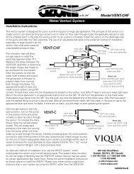
<strong>Motorized</strong> <strong>Alternating</strong> <strong>Valve</strong><br />
Installation Guide for EE and EI<br />
V3069FF • 1” and 1.25”<br />
V3071 or V3071BSPT<br />
1.5”<br />
V3069MM • 1” and 1.25”<br />
V3076 or V3076BSPT<br />
2”
V3069MM 1” and 1.25”<br />
View from top<br />
C<br />
A B<br />
“A” Port “B” Port<br />
Alt. A Alt. B<br />
V3069FF 1” and 1.25”<br />
Operating pressures: 20 psi MiniMuM / 125 psi MaxiMuM • Operating teMperatures: 40°F MINIMUM / 110°F MAXIMUM<br />
1. Plumb the <strong>Motorized</strong> <strong>Alternating</strong> valve according to the photo and drawing attached.<br />
NOTE: The Control <strong>Valve</strong> connected to the “A” port on the <strong>Motorized</strong> <strong>Alternating</strong> <strong>Valve</strong><br />
must be designated “Alt A” during programming. The Control <strong>Valve</strong> connected to the “B”<br />
port on the <strong>Motorized</strong> <strong>Alternating</strong> <strong>Valve</strong> must be designated “Alt B” during programming.<br />
Page 2<br />
M.A.V. Installation Guide
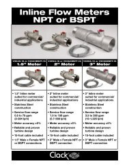
MAV “C” Port<br />
MAV “A” Port MAV “B” Port<br />
V3076 MAV and WS2 valves shown. Diagram is typical for<br />
WS1.5, WS2L, or WS2 valves using V3071 or V3076 piston style<br />
MAV’s and regenerating with hard water.<br />
Outlet<br />
MAV Motor Wire<br />
Inlet<br />
Meter<br />
Communication<br />
Cable<br />
Meter Cable<br />
ALT A<br />
ALT B<br />
Note: These drawings are for reference. Installer<br />
needs to install inlet & outlet isolation ball valves for<br />
each control valve and a three valve bypass for the<br />
system. It is recommended to have some unions in the<br />
plumbing. Meter should be mounted horizontally or in<br />
a downflow vertical position to reduce bearing wear.<br />
Page 3
Page 4<br />
M.A.V. Installation Guide<br />
2. Before connecting the meter, motorized alternating valve (MAV), and interconnect cables, it is<br />
necessary to remove the front cover and drive bracket assemblies for each control valve.<br />
2a. Remove front cover from each control<br />
valve. Pull out on each covers release tabs<br />
located on each side of the cover and pull<br />
cover off.<br />
2b. Disconnect power and meter cables from<br />
each PC Board<br />
2c. Remove drive bracket assembly by pressing up on the drive bracket’s release tabs and<br />
pulling out on the top tabs the drive bracket should come forward for removal.
M.A.V. Installation Guide<br />
3. Once drive bracket is removed, locate knockout on backplate. You can use a punch or a<br />
Phillips screw driver and place it in the center of the knockout circle and tap it with a mild to<br />
medium force with a hammer to punch out circle knockout piece.<br />
4. Re-install drive bracket assemblies and re-connect any disconnected wires back to the proper<br />
location on each PC Board.<br />
Page 5
Alt. A<br />
5. On the backside of “ALT A’s” backplate, located on the lower left hand side, are the strain<br />
relief and knockout hole. These allow you to bring through the MAV valves motor cable and<br />
one end of the interconnect cable.<br />
Page 6<br />
M.A.V. Installation Guide<br />
NOTE: Since two extra cables need to come to control valve<br />
“ALT A” you will need to take pliers and break out the<br />
tabs at the bottom of the strain relief on the backside of<br />
the backplate.
M.A.V. Installation Guide<br />
MAV Motor Cable<br />
Interconnect Cable<br />
Alt. A<br />
6. Connect the MAV motor cable to the two pin connector labeled “DRIVE” on the PC Board and<br />
connect the interconnect cable to the three pin connector labeled “INTERCONNECT CABLE”<br />
on the PC Board on control valve “ALT A”.<br />
6a. After connecting the cables you will need to weave the wires through the strain relief on the<br />
backside of the backplate. Then you take the strain relief cover and screw and fasten the<br />
cover over the top of the strain relief. The cover and screw (V3805) which two are supplied<br />
with V3069FF, V3069MM, V3071, V3071BSPT, V3076 and V3076BSPT MAV valves.<br />
Page 7
Alt. B<br />
7. For control valve “ALT b” the other end of the interconnect cable needs to be routed through<br />
the knockout hole on the backside of the backplate. Connect the end of the interconnect<br />
cable to the three pin connection labeled “INTERCONNECT CABLE” on the PC Board.<br />
8. On the backside of “ALT b” you will need to breakout only one tab at the bottom of the strain<br />
relief for 1” and 1.25” control valves. This will allow to weave the interconnect cable down<br />
through the strain relief so you can install and fasten the strain relief cover over the top of<br />
the strain relief. See step 9 (pg. 9) for 1.5” and 2” control valves.<br />
Page 8<br />
M.A.V. Installation Guide
M.A.V. Installation Guide<br />
Alt. A Alt. B<br />
NOTE:<br />
SINGLE METER APPLICATIONS: When using a single meter (typically 1.5” and 2”) with the<br />
motorized alternating valve it is necessary to use a three wire interconnect cable P/N V3474<br />
between the control valves. The black wire (the one closest to the cut out on the circuit board)<br />
is used to send the meter signal to the other control valve.<br />
DUAL METER APPLICATIONS: When using two meters one on each control valve it is necessary<br />
to use a two wire interconnect cable P/N V3474-01 between the control valves. The black wire<br />
(the one closest to the cut out on the circuit board) is removed being each control receives its<br />
own meter signal. Using a three wire interconnect cable with dual meters will cause the controls<br />
to go into an ERROR. A three wire interconnect cable could be used on a dual meter application<br />
by removing or cutting the black wire (the one closest to the cut out on the circuit board) from<br />
the three wire pin connector.<br />
Page 9
Alt. B<br />
9. SINGLE METER APPLICATIONS: Bring meter cable through knockout hole with<br />
interconnect cable and connect the 15’ water meter cable to the three pin connection<br />
labeled “METER” on the “ALT b” control valve to make wiring easier. However, the<br />
meter can be connected to either “ALT A” or “ALT b”. Connect the interconnect cable<br />
to the three pin connection labeled “INTERCONNECT CABLE”.<br />
Page 10<br />
M.A.V. Installation Guide
M.A.V. Installation Guide<br />
9a. Breakout second tab of “ALT b” strain relief on the backside of the backplate to allow the<br />
water meter cable to be weaved through.<br />
9b.Then fasten the strain relief cover over the top of the strain relief.<br />
Page 11
Page 12<br />
M.A.V. Installation Guide<br />
Alt. A<br />
Alt. B<br />
10. Make sure all wires are connected to proper PC Board connections before programming.<br />
www.clackcorp.com<br />
4462 DURAFORM LANE • WINDSOR, WISCONSIN 53598-9716 USA<br />
p h o n e (608) 846-3010 f a x (608) 846-2586 sales /customer s e r v i c e f a x (800) 755-3010 Form No. 2739 • 9/08/2009