Symmetry:Art and Science - Sint-Lucas
Symmetry:Art and Science - Sint-Lucas
Symmetry:Art and Science - Sint-Lucas

Create successful ePaper yourself
Turn your PDF publications into a flip-book with our unique Google optimized e-Paper software.
<strong>Symmetry</strong>:<strong>Art</strong><br />
<strong>and</strong><br />
Special Issue edited by the<br />
Department for Architecture<br />
<strong>Sint</strong>-<strong>Lucas</strong> Brussels BELGIUM.<br />
The Quarterly of the<br />
International Society for the<br />
Interdisciplinary Study of <strong>Symmetry</strong><br />
(ISIS - <strong>Symmetry</strong>).<br />
<strong>Science</strong><br />
Volume 2 (new series),<br />
numbers 1 - 4, 2002.
<strong>Symmetry</strong>: <strong>Art</strong> <strong>and</strong> <strong>Science</strong> (formerly <strong>Symmetry</strong>: Culture <strong>and</strong> <strong>Science</strong>) is the journal of<br />
the International Society for the Interdisciplinary Study of <strong>Symmetry</strong> (ISIS-<strong>Symmetry</strong>).<br />
The views expressed are those of individual authors <strong>and</strong> not necessarily shared by the<br />
Society or the Editors.<br />
Regular Editors:<br />
George Lugosi<br />
R&D&I (Research-Develop-Invent)<br />
2 Union Street<br />
Kew, Victoria 3101<br />
Australia<br />
Fax: +61-3 9852 – 8344<br />
Email: g.lugosi@hfi.unimelb.edu.au<br />
Dénes Nagy<br />
Institute for the Advancement of Research<br />
Australian Catholic University<br />
Locked Bag 4115, Fitzroy, Victoria 3065<br />
Australia<br />
E-mail: d.nagy@patrick.acu.edu.au<br />
© ISIS-<strong>Symmetry</strong>. No part of this publication may be reproduced without written<br />
permission from the Society.<br />
ISSN 1447- 607X<br />
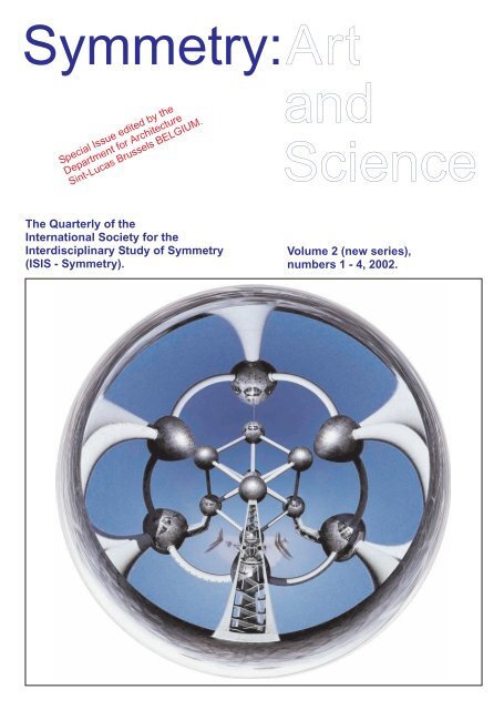
Cover layout: Gunter Schmitz.<br />
Image on the front cover: Atomium Anamorphosis by Phillip Kent.<br />
Images on the back cover: An artistic design by means of an algebraic structure, by<br />
F. Ruiz <strong>and</strong> M. Peñas; 3D model of Schindler’s Braxton House, by Jin-Ho Park.<br />
Ambigram on the back cover by John Langdon (Wordplay, 1992).<br />
Book Production: D. Gillis, Brussels, BELGIUM.<br />
Tel +32 (0)2 522 39 69; fax +32 (0)2 520 03 78; dirk.gillis@gillis.be.
<strong>Symmetry</strong>:<br />
Founding editors: G. Darvas <strong>and</strong> D. Nagy<br />
The Quarterly of the<br />
International Society for the<br />
Interdisciplinary Study of <strong>Symmetry</strong><br />
(ISIS-<strong>Symmetry</strong>)<br />
Published by the International <strong>Symmetry</strong> Foundation.<br />
Volume 2 (New Series), Numbers 1 - 4, 2002.<br />
SPECIAL ISSUE:<br />
Papers presented at the<br />
Mat mium Euro-workshop,<br />
a Regional Congress of ISIS-<strong>Symmetry</strong>,<br />
supported by the European Commission.<br />
Guest Editing:<br />
Department of Architecture <strong>Sint</strong>-<strong>Lucas</strong> Brussels, BELGIUM.<br />
1
EDITORIAL<br />
This issue contains papers presented at the Euro-workshop Mat mium in Brussels, held<br />
9-13 April 2002 at the Department for Architecture <strong>Sint</strong>-<strong>Lucas</strong> in Brussels, Belgium.<br />
The Congress was co-presided by Dénes Nagy with the collaboration of Slavik Jablan.<br />
The papers are arranged in order of participation.<br />
The cover followed the ISIS format, <strong>and</strong> thus it was printed on soft paper. A hard cover<br />
would have been more suitable, but then the larger ISIS network would not have been<br />
accessible for its distribution. Eric Blanckaert took most of the photos on the different<br />
locations.<br />
An apology is owed because of the delay in the publication of these proceedings.<br />
However, there is a very good reason: after a heavy traveling schedule, Dénes Nagy fell<br />
ill. Actually, while this issue was prepared, he was still recovering from treatment. We<br />
express our thanks to all participants for their patience, <strong>and</strong> to all authors for their<br />
assistance <strong>and</strong> underst<strong>and</strong>ing in preparing this issue.<br />
The Euro-workshop Mat mium was supported by the European Commission, Research<br />
DG, Human Potential Programme, High-Level Scientific Conferences, under contract<br />
number HPCF-2001-00377.<br />
The information provided is the sole responsibility of the authors <strong>and</strong> does not reflect<br />
the Community's opinion. The Community is not responsible for any use that might be<br />
made of data appearing in this publication.<br />
2
CONTENTS<br />
Event Page<br />
Day 1, At the Atomium, 2002 April 9<br />
Presentation of the speakers<br />
Special Feature: TV-Brussels broadcast.<br />
1.Metadesign, LAB[AU] Laboratory for Architecture <strong>and</strong> Urbanism. 19<br />
2. Footprints Literacy: The Origins of <strong>Art</strong> <strong>and</strong> Prelude to <strong>Science</strong>, Tsion<br />
Avital.<br />
23<br />
Day 2, At the Institute Architecture, 2002 April 10<br />
25<br />
Special Feature: Fractal art exposition.<br />
26<br />
1. Architecture, mathematics, <strong>and</strong> a “symmetric link” between them (From the 31<br />
Atomium building to the Mat mium project), Dénes Nagy.<br />
2. The Role of Mathematics in the Gothic Architecture Structural Analysis,<br />
Javier Barallo.<br />
65<br />
3. From Itten’s Tower to Virtual Towers: a generative Algorithm, Elena<br />
Marchetti <strong>and</strong> Luisa Rossi Costa.<br />
75<br />
4. Programmed Design: The Systematic Method <strong>and</strong> the Form of Pattern,<br />
Karen Y. Li.<br />
85<br />
5. Defining Basic Design as a Discipline, William S. Huff. 91<br />
6. Design <strong>and</strong> Cognition: Contribution to a Design Theory, Claudio Guerri.<br />
7. Growth, Curvature <strong>and</strong> Computation, Chaim Goodman-Strauss.<br />
99<br />
111<br />
8. Sliceform, Surfaces <strong>and</strong> a Serendipitous Discovery, John Sharp. 123<br />
9. <strong>Art</strong> of Anamorphosis, Phillip Kent. 131<br />
10. Basic Crystal Symmetries Generated by Molecular Dimers, Alajos<br />
Kalman, Laszlo Fabian <strong>and</strong> Andrea B. Deak.<br />
135<br />
Day 3, At the Africa Museum of Tervuren, 2002 April 11<br />
139<br />
Special Feature: conference movie<br />
142<br />
1. Folded Structures, Tibor Tarnai. 147<br />
2. <strong>Symmetry</strong> <strong>and</strong> Ornament, Slavik Jablan. 161<br />
3. How Plato Designed Atlantis, Leslie Greenhill. 163<br />
4. The Mnemonics of the Cretan Labyrinth, Tessa Morrison. 203<br />
5. The Parthenon Design Measurements, Anne Bulckens. 219<br />
6. <strong>Art</strong>istic Designs by Means of Algebraic Structures, F. Ruiz <strong>and</strong> M. Peñas. 231<br />
7. Form World – Generated by Integer Permutation, George Lugosi. 251<br />
8. Visualization vs. Verbalization, Insight into the Morphology of Polyhedra,<br />
Irit Wertheim <strong>and</strong> Nitsa Movshovitz-Hadar.<br />
255<br />
9. Virus Model, Florian Kovacs. 265<br />
3<br />
5<br />
6<br />
16
Day 4, At the Horta van Eetvelde Hotel, 2002 April 12<br />
269<br />
Special Feature: conference cartoons<br />
270<br />
1. Pattern Design by Improper Use of Mathcad, Patrick Labarque. 275<br />
2. Growing Visible, Nonexistent Trees <strong>and</strong> Building four-Dimensional<br />
Polytopes, Virpi Kauko.<br />
281<br />
3. Virtual <strong>and</strong> Real States – The Structure of Things <strong>and</strong> Objects, Tomek<br />
Michniowski.<br />
287<br />
4. Tessellations of Euclidean, Riemannian <strong>and</strong> Hyperbolic Plane, Radmila<br />
Sazdanovic <strong>and</strong> Miodrag Sremcevic.<br />
299<br />
5. A Remarkable Horta Type Spiral, Annie Van Maldeghem. 305<br />
6. Rudolph M. Schindler’s Braxton House: The Fibonacci <strong>and</strong> <strong>Lucas</strong> Series,<br />
Jin-Ho Park.<br />
313<br />
7. An Unexpected Encounter with the Mathematician E. B. Christoffel, Helena<br />
Alex<strong>and</strong>ra <strong>and</strong> Robert Willem Van der Waall.<br />
325<br />
8. SPACE PRODUCTION, 51N4E. 333<br />
9. Frustration: Source of Complexity, Tohru Ogawa. 351<br />
10. Digital Shaping of Spatial Structures, Janusz Rebielak. 353<br />
11. Proportions <strong>and</strong> Dissections in Polygons, Encarnacion Reyes Iglesias. 357<br />
12. Gothic Town Halls in <strong>and</strong> Around Fl<strong>and</strong>ers, 1350-1550: A Geometrical<br />
Analysis, Han V<strong>and</strong>evyvere.<br />
365<br />
13. Nonperiodic Selfsimilar Tilings <strong>and</strong> <strong>Symmetry</strong>, Dirk Frettloeh. 379<br />
14. <strong>Symmetry</strong> Groups in Mathematics, Architecture <strong>and</strong> <strong>Art</strong>, Vera Winitzky de<br />
Spinadel.<br />
385<br />
15. Useful Mathematics: Advantages of Decentralized Electricity <strong>and</strong> Heat<br />
Supply for Buildings, using Fuel Cells, Erico Spinadel.<br />
403<br />
Day 5, Bruges, 2002 April 13. 415<br />
4
Location.<br />
Day 1<br />
At the Atomium, 2002 April 9.<br />
The location for the first days’ talks was the<br />
Atomium, the lasting symbol of the 1958<br />
Brussels World's Fair <strong>and</strong> Belgium's answer<br />
to the Eiffel Tower or the Statue of Liberty.<br />
Architects André <strong>and</strong> Jean Polak realized the<br />
project together with engineer André<br />
Waterkeyn. The Atomium became<br />
Belgium’s l<strong>and</strong>mark, <strong>and</strong> one of the most<br />
visited attractions in the country.<br />
The first session at the Atomium started with the presentation of the participants, in<br />
“order of appearance”, by the chairpersons of each day:<br />
- Day 1: ATOMIUM: Dirk Huylebrouck, Brussels.<br />
- Day 2: W&K ARCHITECTUUR: Patrick Labarque, Brussels.<br />
- Day 3: AFRICAN MUSEUM TERVUREN: Dénes Nagy, Melbourne.<br />
- Day 4: HOTEL VAN EETVELDE, VICTOR HORTA: Slavik Jablan, Belgrade.<br />
5
PRESENTATION OF THE SPEAKERS<br />
51N4E Space Producers<br />
"SPACE PRODUCTION"<br />
Arch. Peter Swinnen<br />
<strong>Sint</strong>-<strong>Lucas</strong> Brussels, Architectural Association<br />
London; editor for Financieel Economische Tijd, de<br />
Architect; coordinator Stichting Stad & Architectuur<br />
Leuven.<br />
Arch. Freek Persyn<br />
<strong>Sint</strong>-<strong>Lucas</strong> Brussels, collaborator Xaveer de Geyter<br />
Architecten.<br />
Arch. Johan Anrys<br />
<strong>Sint</strong>-<strong>Lucas</strong> Brussels, tutor architecture design<br />
Campus Faydherbe Mechelen.<br />
Brussels<br />
BELGIUM<br />
51n4e@pi.be.<br />
Tsion AVITAL<br />
"FOOTPRINTS LITERACY: THE ORIGINS OF ART AND<br />
PRELUDE TO SCIENCE"<br />
Holon Academic Institute of Technology<br />
Department of Design <strong>and</strong> <strong>Art</strong>, Holon Campus,<br />
Holon<br />
ISRAEL<br />
avital@hait.ac.il<br />
www.hait.ac.il/staff/Avital/Avital.htm<br />
Javier BARRALLO<br />
"THE ROLE OF MATHEMATICS IN THE GOTHIC<br />
ARCHITECTURE STRUCTURAL ANALYSIS"<br />
University of the Basque Country,<br />
San Sebastian<br />
SPAIN<br />
mapbacaj@telepolis.com<br />
www.sc.ehu.es/mathema1/BelVie.htm<br />
www.sc.ehu.es/mathema1/Anglet.htm<br />
www.sc.ehu.es/mathema1/fas.html<br />
6
Anne BULCKENS<br />
"THE PARTHENON DESIGN MEASUREMENTS"<br />
Dr in Architecture<br />
Jakarta<br />
INDONESIA.<br />
annepaul@cbn.net.id<br />
Luisa Rossi COSTA<br />
"WORKING WITH AFFINE TRANSFORMATION: THREE<br />
VIRTUAL TOWERS"<br />
Dipartimento di Matematica "F.Brioschi"<br />
Politecnico di Milano<br />
Milano<br />
ITALY.<br />
luiros@mate.polimi.it<br />
Vera W. de Spinadel<br />
"SYMMETRY GROUPS IN MATHEMATICS,<br />
ARCHITECTURE AND ART"<br />
Director of the Center of Mathematics & Design MAyDI<br />
Faculty of Architecture, Design <strong>and</strong> Urban Studies<br />
University of Buenos Aires<br />
Buenos Aires<br />
ARGENTINA.<br />
vspinade@fibertel.com.ar<br />
Erico de SPINADEL<br />
"USEFUL MATHEMATICS: ADVANTAGES OF<br />
DECENTRALIZED ELECTRICITY AND HEAT SUPPLY FOR<br />
BUILDINGS, USING FUEL CELLS"<br />
Argentine Wind Energy Association AAEE<br />
University FASTA<br />
Mar del Plata<br />
ARGENTINA.<br />
vspinade@fibertel.com<br />
7
Laszlo FABIAN<br />
"BASIC CRYSTAL SYMMETRIES GENERATED BY<br />
MOLECULAR DIMERS"<br />
Junior research assistant<br />
Chemical Research Center<br />
Hung. Acad. Sci.<br />
Budapest<br />
HUNGARY.<br />
Dirk FRETTLOEH<br />
"NONPERIODIC SELFSIMILAR TILINGS AND SYMMETRY"<br />
Dipl. Math.<br />
FB Mathematik<br />
Universitaet Dortmund<br />
Dortmund<br />
GERMANY.<br />
Dirk.Frettloeh@udo.edu<br />
Chaim GOODMAN-STRAUSS<br />
"NEW MODELS OF GROWTH AND FORM"<br />
Mathematician, graphic designer, artist.<br />
Dept. Mathematics<br />
Univ. Arkansas<br />
Fayetteville<br />
USA.<br />
cgstraus@comp.uark.edu<br />
www.delojo.com/be.html<br />
Leslie GREENHILL<br />
"HOW PLATO DESIGNED ATLANTIS"<br />
Dip. P.S.P.<br />
Educated at the Royal Melbourne Institute of Technology<br />
Background in public education <strong>and</strong> public affairs in State<br />
government in Victoria, Australia. He presented early findings on<br />
ancient design systems at the World Mathematical Year 2000<br />
Conference at the University of Melbourne.<br />
AUSTRALIA.<br />
lesgreenhill@yahoo.com.au<br />
8
Claudio GUERRI<br />
"DESIGN AND COGNITION: CONTRIBUTION TO A DESIGN<br />
THEORY"<br />
Architect<br />
Buenos Aires<br />
ARGENTINA.<br />
claudioguerri@fibertel.com.ar<br />
William S. HUFF<br />
"DEFINING BASIC DESIGN AS A DISCIPLINE"<br />
Professor Emeritus<br />
State University of New York at Buffalo<br />
USA.<br />
wshuff@earthlink.net<br />
Slavik JABLAN<br />
"SYMMETRY AND ORNAMENT"<br />
Mathematical Institute<br />
Belgrade<br />
YUGOSLAVIA.<br />
jablans@mi.sanu.ac.yu .<br />
www.mi.sanu.ac.yu/~jablans/<br />
Alajos KALMAN<br />
"BASIC CRYSTAL SYMMETRIES GENERATED BY<br />
MOLECULAR DIMERS"<br />
Ph.D., D.Sc., FASc<br />
President of the Hungarian Chemical Society<br />
Chemical Research Center<br />
Hung. Acad. Sci.<br />
Budapest<br />
HUNGARY.<br />
akalman@chemres.hu<br />
9
Virpi KAUKO<br />
"GROWING VISIBLE, NONEXISTENT TREES AND<br />
BUILDING FOUR-DIMENSIONAL POLYTOPES"<br />
Department of Mathematics <strong>and</strong> Statistics<br />
University of Jyväskylä<br />
Jyväskylä<br />
FINLAND.<br />
virpik@maths.jyu.fi<br />
Phillip KENT<br />
"ART OF ANAMORPHOSIS"<br />
School of Mathematics, <strong>Science</strong> <strong>and</strong> Technology<br />
Institute of Education<br />
London<br />
UNITED KINGDOM.<br />
p.kent@mail.com<br />
www.anamorphosis.com<br />
Patrick LABARQUE<br />
"PATTERN DESIGN BY IMPROPER USE OF MATHCAD"<br />
Architect<br />
Hogeschool voor Wetenschap & Kunst<br />
Departement "<strong>Sint</strong>-<strong>Lucas</strong>" Architectuur, campus Brussel<br />
Brussels<br />
BELGIUM<br />
patrick.labarque@archb.sintlucas.wenk.be<br />
LAB[au]<br />
"://> project - sPACE, navigable music"<br />
LAB[au] = laboratory for architecture <strong>and</strong> urbanism<br />
M. Abendroth, J. Decock,<br />
A. Plennevaux, G.Verhaegen.<br />
BELGIUM – GERMANY.<br />
lab-au@lab-au.com<br />
www.lab-au.com<br />
www.lab-au.com/space<br />
10
Karen Yuqing LI<br />
"PATTERNS OF SYMMETRY AND ANTISYMMETRY -<br />
A PROGRAM DESIGN"<br />
Designer Architect<br />
Pittsburgh<br />
USA<br />
Karen_yli@yahoo.com<br />
George LUGOSI<br />
"FORM WORLD - GENERATED BY INTEGER<br />
PERMUTATION"<br />
Chemical Engineer, Electronic Engineer, Patent Attorney<br />
Director of Forarc Pty. Ltd., R&D&I (Research, Development,<br />
Inventions) trading. Former Computer Scientist at Howard Florey<br />
Institute, University of Melbourne<br />
Melbourne.<br />
AUSTRALIA.<br />
g.lugosi@hfi.unimelb.edu.au<br />
Elena MARCHETTI<br />
"WORKING WITH AFFINE TRANSFORMATION: THREE<br />
VIRTUAL TOWERS"<br />
Dipartimento di Matematica "F.Brioschi"<br />
Politecnico di Milano<br />
Milano<br />
ITALY.<br />
luiros@mate.polimi.it<br />
Tomasz MICHNIOWSKI<br />
"VIRTUAL AND REAL STATES - THE STRUCTURE OF<br />
THINGS AND OBJECTS"<br />
Surname: Tomek.<br />
pool@kul.lublin.pl<br />
11
Tessa MORRISON<br />
"THE MNEMONICS OF THE CRETAN LABYRINTH"<br />
School of Fine <strong>Art</strong>s<br />
The University of Newcastle<br />
Newcastle<br />
AUSTRALIA.<br />
c9520975@alinga.newcastle.edu.au<br />
Nitsa MOVSHOVITZ-HADAR<br />
"VISUALIZATION VS. VERBALIZATION, INSIGHT INTO<br />
THE MORPHOLOGY OF POLYHEDRA"<br />
Ph.D., Head of Kesher Cham - National Center for Mathematics<br />
Education, Director of the Israel National Museum of <strong>Science</strong>,<br />
Planning, <strong>and</strong> Technology<br />
Technion<br />
ISRAEL.<br />
nitsa@techunix.technion.ac.il<br />
Denes NAGY<br />
"INFORM-A-TOMIUM"<br />
Nagy is the president of the ISIS Society.<br />
d.nagy@patrick.acu.edu.au<br />
Tohru OGAWA<br />
"FRUSTRATION: SOURCE OF COMPLEXITY"<br />
Japan.<br />
He renewed upon a paper written together with Y. Nakajima:<br />
Frustration, Degeneracy, <strong>and</strong> Forms: A View of the<br />
Antiferromagnetic Ising Model on a Triangular Lattice,<br />
Progress of Theoretical Physics, Supplement No. 87 (1986), pp.<br />
90-101.<br />
JAPAN.<br />
ogawa-t@koalanet.ne.jp<br />
12
Jin-Ho PARK<br />
"RUDOLPH M. SCHINDLER’S BRAXTON HOUSE: THE<br />
FIBONACCI AND LUCAS SERIES"<br />
School of Architecture<br />
University of Hawaii at Manoa<br />
Honolulu<br />
USA.<br />
jinhpark@hawaii.edu<br />
Maria PENAS<br />
"ARTISTIC DESIGNS BY MEANS OF ALGEBRAIC<br />
STRUCTURES"<br />
Department of Didactics of Mathematics<br />
University of Granada<br />
Faculty of Education<br />
Campus de Cartuja<br />
Granada<br />
SPAIN.<br />
mtroyano@ugr.es<br />
Janusz REBIELAK<br />
"DIGITAL SHAPING OF SPATIAL STRUCTURES"<br />
Professor at Wroclaw University of Technology<br />
Department of Architecture<br />
Wroclaw<br />
POLAND<br />
j.rebielak@wp.pl<br />
Encarnacion REYES IGLESIAS<br />
"PROPORTIONS AND DISSECTIONS IN POLYGONS"<br />
Mathematician.<br />
Departamento de Matemática Aplicada Fundamental<br />
E.T.S. Arquitectura<br />
University of Valladolid<br />
Volladolid<br />
SPAIN.<br />
ereyes@maf.uva.es<br />
13
Francisco RUIZ<br />
"ARTISTIC DESIGNS BY MEANS OF ALGEBRAIC<br />
STRUCTURES"<br />
Department of Didactics of Mathematics<br />
University of Granada Faculty of Education<br />
Campus de Cartuja<br />
Granada<br />
SPAIN.<br />
fcoruiz@ugr.es<br />
Radmila SAZDANOVIC<br />
"TESSELATIONS OF EUCLIDEAN, RIEMANNIAN AND<br />
HYPERBOLIC PLANE"<br />
Faculty of Mathematics<br />
University of Belgrade<br />
Belgrade<br />
Yugoslavia<br />
seasmile@galeb.etf.bg.ac.yu<br />
John SHARP<br />
"SLICEFORM SURFACES AND A SERENDIPITOUS<br />
DISCOVERY"<br />
Watford Herts<br />
ENGLAND.<br />
Sliceforms@compuserve.com<br />
www.counton.org/explorer/sliceforms ,<br />
www.nmsi.ac.uk/visitors/surfaces/<br />
Tibor TARNAI<br />
"FOLDED STRUCTURES"<br />
Member of the Hungarian Academy of <strong>Science</strong>s<br />
Budapest University of Technology <strong>and</strong> Economics<br />
Budapest<br />
HUNGARY.<br />
tarnai@ep-mech.me.bme.hu<br />
14
R.W. VAN DER WAALL<br />
"AN UNEXPECTED ENCOUNTER WITH THE<br />
MATHEMATICIAN E.B.CRISTOFFEL"<br />
KdV-Instituut, Universiteit Amsterdam<br />
Amsterdam<br />
THE NETHERLANDS.<br />
waallr@science.uva.nl<br />
Han VANDEVYVERE<br />
"GOTHIC TOWN HALLS IN AND AROUND FLANDERS,<br />
1350-1550: A GEOMETRICAL ANALYSIS"<br />
ir.-arch.<br />
Research group caad <strong>and</strong> design methodology<br />
Departement architectuur, stedenbouw en ruimtelijke ordening<br />
K.U.Leuven<br />
Leuven<br />
BELGIUM.<br />
asro.kuleuven.ac.be.<br />
Annie VAN MALDEGHEM<br />
"A REMARKABLE HORTA TYPE SPIRAL"<br />
Hogeschool voor Wetenschap & Kunst<br />
Departement "<strong>Sint</strong>-<strong>Lucas</strong>" Architectuur, campus Gent<br />
Ghent<br />
BELGIUM.<br />
annie_van_maldeghem@yahoo.com<br />
Irit WERTHEIM<br />
"VISUALIZATION VS. VERBALIZATION, INSIGHT INTO<br />
THE MORPHOLOGY OF POLYHEDRA"<br />
Architect, Ph.D.<br />
Technion – Israel Institute of Technology<br />
Department of Education in <strong>Science</strong> <strong>and</strong> technology<br />
Haifa<br />
ISRAEL.<br />
Main research: morphological approach to 3-D geometry.<br />
weririt@techunix.technion.ac.il.<br />
15
Special Feature: TV-Brussels broadcast.<br />
TV Brussels is the local TV-station<br />
in Brussels. Some sites are:<br />
http://www.tv-brussel.irisnet.be/<br />
http://tv-brussel.vgc.be/ .<br />
This TV station broadcasted briefly on the Mat mium event, during its news broadcast.<br />
Below are some images from that broadcast.<br />
General view on the conference room,<br />
inside one of the spheres of the Atomium.<br />
D. Nagy during his introduction.<br />
16<br />
D. Nagy <strong>and</strong> T. Tarnai, attentively<br />
listening to the introduction.<br />
D. Nagy linked Horta to mathematics <strong>and</strong><br />
the Belgian environment.
Next was LABau’s turn, with a musical<br />
performance inside the Atomium.<br />
“What we demonstrate here tonight is<br />
called: Space Navigable Music.<br />
The project was initially meant for the<br />
Internet …<br />
17<br />
It took a lot of preparation to get<br />
everything installed in the 9 spheres<br />
building with its many stairs <strong>and</strong><br />
escalators.<br />
The project links architecture, music <strong>and</strong><br />
images.<br />
... but it has grown to a live-act with<br />
musicians.
The project is based on a very simple<br />
principle.<br />
By moving though that space, you make<br />
music.<br />
LABau’s presenter became part of his own<br />
show.<br />
18<br />
One has a three-dimensional space where<br />
movement is free.<br />
You can record your music <strong>and</strong> let your<br />
friends listen to it through the Internet.”<br />
Spectators came in large numbers, <strong>and</strong><br />
even had to sit on the ground
METADESIGN.<br />
LAB[AU] LABORATORY FOR ARCHITECTURE AND URBANISM<br />
Name: LAB[au] is Manuel Abendroth, Jérôme Decock, Alex<strong>and</strong>re Plennevaux.<br />
Address: 19, Quai au Foin, B-1000 Brussels.<br />
E-mail: lab-au@lab-au.com<br />
Fields of interest: Architecture, urbanism, interfaces, new technologies of information <strong>and</strong> communication.<br />
Awards: 2002, ‘Culture2002’ first prize in category <strong>Art</strong> for the project ‘Worldebt, you can count on it’<br />
http://www.encorebruxelles.org/jk 1999: 'Prix de la Brique Belge', 'Lightscape(s), displacement maps' - light<br />
plan study for the Heizel plateau http://www.lab-au.com/lightsc 'Tech-art prize', Vlaamse Ingenieurs Kamer.<br />
Publications <strong>and</strong>/or Exhibitions: A+ magazine, nr. 168 April-May 2001 'http://mind space', A+ magazine, nr.<br />
172 Dec.2001/ Jan.2001 'http://e.motional space', A+ magazine, nr. 173 Feb./March 2002 'http://soundspace'<br />
Keywords: Hypermedia – sonic space – soundscapes - inFORMation processes – connectivity - eSPACE<br />
CONSTRUCTionS.<br />
Abstract: The transposition of inFORMation processes, transmission <strong>and</strong> computation,<br />
in textual, graphical bi-dimensional, three-dimensional <strong>and</strong> biomorphic (autogenerative;<br />
n-dimensional) forms explores new constructs proper to the electronic<br />
medium <strong>and</strong> outlines the spatial <strong>and</strong> semantic mutation provoked by technologies on the<br />
perception <strong>and</strong> conception of our environment. ‘Metadesign’ thus can be understood as<br />
a technology determinism that constitutes the main vector/thought in the concern of<br />
networked, information-based societies.<br />
1 METADESIGN<br />
A technology is not an independent or alien object, it complements integrally our<br />
sensorial <strong>and</strong> cognitive system; as a medium, it conditions not only communication<br />
modes but also the way we perceive <strong>and</strong> conceive our environment.<br />
The increasing implication of communication <strong>and</strong> information technologies in the<br />
process of production <strong>and</strong> knowledge leads to the fundamental re-thinking of the<br />
organization <strong>and</strong> definition of space. Technology based on the transmission <strong>and</strong><br />
computation of information influences organization models (modes of production, work<br />
<strong>and</strong> knowledge) <strong>and</strong> affects the communication process (code, symbol) <strong>and</strong> the social<br />
relations as well as their spatialization. The affectation of traditional articulations<br />
19
etween information, space <strong>and</strong> time leads to the augmenting need to flatten the<br />
electronic realm into the concrete space.<br />
If, as all communication systems, new technologies induce a transmission channel<br />
(signal-medium), a message (information) <strong>and</strong> a code, their property is to operate on any<br />
kind of information, even space, a reduction in a sequence of elementary information<br />
coded in a binary language, 0/1 or bit/second. However, contrary to its analogue<br />
counterparts within which information was materially fixed on a medium, the digital<br />
media celebrate the loss of inscription; it is the transposition of all stable “FORM” into<br />
transmissible <strong>and</strong> editable “inFORMation”, processes.<br />
As a consequence, the investigation in information space constructs shows the shift from<br />
traditional architecture into a metadesign, exploring new spatio-temporal structures as<br />
well as their representation practices such as architecture <strong>and</strong> urbanism. New<br />
technologies therefore perform a transformation on semantic <strong>and</strong> spatial structures<br />
(architecture) as much on the level of language (code, style) as on other levels such as<br />
social/spatial/economical/political relations. “e-SPACE CONSTRUCTionS” display the<br />
theme of new space constructs relative to information processes, as the formalizations of<br />
communication <strong>and</strong> computation processes.<br />
In relation to >INFORMation< processes, metadesign is Information architecture,<br />
related to the structuring of information, its textual, graphical, spatial <strong>and</strong> biomorphic<br />
transcription <strong>and</strong> interfacing grounded on the inherent logics of computation <strong>and</strong><br />
communication technology in networked societies.<br />
Metadesign deals with the setting of new ‘senses’ as components of language, while<br />
improving, increasing our cognitive capacities <strong>and</strong> influencing in a major way our<br />
psychic state (consciousness), our emotional <strong>and</strong> social behavior <strong>and</strong> thus participate as<br />
much in the individual project as to the collective. Consequently, in the field of new<br />
medias, it is important to underst<strong>and</strong> the relation, which is established between<br />
perception (the use of senses), recognition, comprehension <strong>and</strong> the representation (the<br />
extraction of sense/meaning), <strong>and</strong> the action that results from it (production of<br />
sense/meaning).<br />
In this manner, information architecture deals with intelligible electronic constructs not<br />
only as modalities of perception <strong>and</strong> cognition, but as mental <strong>and</strong> psychic settings of<br />
behavior, ontological concerns, as well as the production of active <strong>and</strong> functional space<br />
settings, spaces of intervention within the constitution of e.SPACE CONSTRUCTionS.<br />
Metadesign thus deals with information as programming <strong>and</strong> meta-inscription, versus as<br />
an output of interpretation - <strong>and</strong> data as objective reality versus information as narrative<br />
<strong>and</strong> simulation. ‘Metadesign’ displays the theme of new space constructs relative to<br />
information processes, as the formalizations of communication <strong>and</strong> computation<br />
processes according to social, semantic <strong>and</strong> spatial structures (architecture) as much on<br />
20
the level of language (code, structure) in order to build up connectivity <strong>and</strong><br />
effectiveness.<br />
1.1 “Space, navigable music” project<br />
Figure 1: screen of the online project “space, navigable music” (http://www.labau.com/space).<br />
‘sPACE, Navigable Music’ is an online project investigating the impact of IC<br />
technologies <strong>and</strong> particularly, 3D Real Time modeling languages (such as VRML) in the<br />
construct of space. According to the objectives of LAB[au] the project constitutes as<br />
much a space for theoretical research as a space of experimentation on the forms of<br />
interactions in networked systems exploring the possibilities of space settings in shared<br />
processes in order to build up connectivity.<br />
In sPACE, navigable music, the object or architecture is generated in real time<br />
according to the position <strong>and</strong> movements of the user (mix color, mix image, mix sound).<br />
Operating on structural parameters, the integration (recombination) of spatial (x,y,z),<br />
temporal (t-movements) sonic (frequency, pitch) <strong>and</strong> generative image sequencing<br />
functions, each interaction by the user, displacement, transforms this visual <strong>and</strong> sonic<br />
environment. In addition, the recording of movements allows users to produce a<br />
traveling according to camera movements, montage <strong>and</strong> image sequencing. The<br />
21
established relation between the spatial, visual <strong>and</strong> sonic formalization processes <strong>and</strong> the<br />
editable interactivity of users lead to an experience combining architecture, music <strong>and</strong><br />
cinematic techniques through movement patterns. The ‘Navigable Music’ thus<br />
constitutes a space, in which the user experiments cyberspace by dropping sounds into<br />
space, mixing music throughout space <strong>and</strong> navigation, record its movements to produce<br />
an animation, a traveling in its sonic space architecture, a kinetic music clip.<br />
As such, inFORMation processes, computation <strong>and</strong> communication through codes /<br />
language, VRML, thus describe programmatic relations between these different media<br />
fusing them into a hypermedia, which can be experimented through networks, extending<br />
the construct of space to the digital matrix (mixed reality), where the multi-user space<br />
even more enlarges this experience to shared <strong>and</strong> collaborative processes based on<br />
sound <strong>and</strong> e.space.<br />
Year the Work was created: 2001<br />
Project URL: http://www.lab-au.com/space<br />
Technical requirements: VRML, Blaxxun 5 plug-in, Flash player.<br />
22
FOOTPRINTS LITERACY: THE ORIGINS OF ART<br />
AND PRELUDE TO SCIENCE.<br />
Tsion AVITAL<br />
Abstract: <strong>Art</strong> is a far too complex cultural phenomenon to have been invented ex-nihilo.<br />
However, no adequate explanation has so far been given regarding the graphic <strong>and</strong><br />
cognitive skills, which preceded prehistoric art, <strong>and</strong> made its actual emergence<br />
possible. This essay proposes that prehistoric art was preceded by a more primitive<br />
kind of pictorial literacy, namely footprints literacy. The obvious attribute common to<br />
many early prehistoric paintings <strong>and</strong> footprints is that both represent their subjects by<br />
contour <strong>and</strong> negative. A deeper analysis of these two kinds of visual literacy reveals<br />
many other common attributes: connectivity-differentiation, classification, abstraction,<br />
generalization, signification, visual class-names, symmetry-asymmetry, schematization,<br />
complementarity, induction, deduction, hypothetical thinking <strong>and</strong> others. Thus, it is<br />
probable that footprints are the proto-symbols from which figurative art evolved. It is<br />
striking that the same attributes which appear in footprints literacy about 4 millions of<br />
years ago <strong>and</strong> in figurative art since its beginning about 40.000 years ago, appear<br />
much later as basic attributes of modern science, but at a much higher level of<br />
sophistication. Possibly, these three domains represent successive stages of noetic<br />
evolution. Probably, this finding points to fundamental cognitive attributes or<br />
"mindprints" that are basic not only to these areas, but also to human intelligence itself<br />
<strong>and</strong> probably to all other phases of Being. Pointing out the origins of art might be a<br />
substantial contribution to the lifting of the veil from the most fundamental attributes of<br />
art since its very beginnings. This may provide a new key to the delineation of the<br />
demarcation lines between art <strong>and</strong> non-art, which seems to be the most haunting<br />
problem of modern art. It can be shown that works of nonrepresentational art do not<br />
share those unique fundamental attributes or mind prints shared by footprints literacy,<br />
figurative art, science <strong>and</strong> other branches of culture. Hence, there is room for doubts if<br />
works of nonrepresentational art are culturally relevant <strong>and</strong> if they are works of art at<br />
all.<br />
23
This contribution was related to the publication Footprints Literacy: The Origins of <strong>Art</strong><br />
<strong>and</strong> Prelude to <strong>Science</strong>, <strong>Symmetry</strong>: Culture <strong>and</strong> <strong>Science</strong>. Vol. 9. No. 1. pp. 3-46 (1998),<br />
<strong>and</strong> to a special volume of the ISIS journal (Vol. 1, No, 2, 1999). An electronic<br />
reference is Visual Mathematics, at the Internet address members.tripod.com/vismath/ .<br />
The talk served as "opening act" to mark the aimed level of abstraction, scope,<br />
interconnectedness <strong>and</strong> directness. It gave the participants a feeling they were allowed to<br />
really speak their mind, <strong>and</strong> to the best of their ability.<br />
Avital worked all his life to develop new ideas, rather than repeating old stuff. He was<br />
really involved in his own research, intellectually <strong>and</strong> emotionally. Therefore, he states,<br />
simple-minded conformists get angry because they have never read about it before <strong>and</strong><br />
they think it is outrageous that one dares to speak his mind. The truly intelligent <strong>and</strong><br />
open-minded people get excited because they are exposed to new ideas. For sure, one<br />
way or the other his audience is never indifferent: those who hate his ideas <strong>and</strong> those<br />
who love them, feel that he talks about something that many feel but do not dare to<br />
express or do not have the words <strong>and</strong> underst<strong>and</strong>ing to express.<br />
24
Location.<br />
Day 2<br />
At the Institute for Architecture, 2002 April 10.<br />
The location for the first full day of the<br />
Mat mium conference, <strong>and</strong> the base location of<br />
the organization, was the W&K Institute for<br />
Architecture, W&K being short notation for the<br />
Dutch words Wetenschap (science) <strong>and</strong> Kunst<br />
(art). The contributions of this chapter were<br />
presented there.<br />
The participants were embedded in the Brussels’<br />
environment by an additional evening visit to the<br />
Gr<strong>and</strong>-Place of Brussels, a m<strong>and</strong>atory tourist spot<br />
for every dedicated artist or architect.<br />
25
Special Feature: Fractal art exposition.<br />
At this location, during the time of the Mat mium workshop, a mathematical art<br />
exposition was simultaneously held at the W&K Institute for Architecture. The initiative<br />
for this exposition was due to Prof. Javier Barallo, of the University of the Basque<br />
Country (Spain), or, in the Bask language "Euskal Herriko Unibertsitatea Donostia” or<br />
else, in Spanish, "Universidad del Pais Vasco San Sebastian”.<br />
Barallo’s group The border between <strong>Art</strong> <strong>and</strong> <strong>Science</strong> made its first exposition in<br />
September 1997. Since then, it realized numerous exhibitions in Germany, Argentina,<br />
Austria, Brazil, Spain, France, Japan <strong>and</strong> Serbia-Montenegro (Yugoslavia). The<br />
paintings are grouped under the denominator “The Frontier between <strong>Art</strong> <strong>and</strong> <strong>Science</strong>”.<br />
After the Mat mium workshop, the exposition moved to another Belgian city, Ghent,<br />
where it was shown in a major high school for a broad audience.<br />
This survey exposition consists of works by different authors. They all share the use of<br />
mathematics in their work. All canvasses were made with computer programs, in which<br />
mathematical formulas, based on fractals, were especially designed for the graphical<br />
representation. The mathematical form <strong>and</strong> the used parameters give to each image a<br />
unique <strong>and</strong> singular structure, form <strong>and</strong> color.<br />
Each author works meticulously on his oeuvre by trying different values for the<br />
equations, formulas <strong>and</strong> parameters. In this way, the final image was obtained. Such a<br />
canvas should not be seen as a synthetic, cold <strong>and</strong> mechanically generated image set up<br />
by a computer, but as an artistic expression capable of transferring emotion <strong>and</strong><br />
sensitivity.<br />
For more information, see: www.sc.ehu.es/mathema1/Anglet.htm,<br />
www.sc.ehu.es/mathema1/BelVie.htm, or www.sc.ehu.es/mathema1/fas.html. If you<br />
would like to have the exposition at your university or hometown, please do contact<br />
Prof. Javier Barallo (mapbacaj@telepolis.com).<br />
Below, the 12 images shown in Belgium are presented, but of course infinitely more<br />
fractals are available. This artwork is copy right protected, <strong>and</strong> thus shown here in very<br />
reduced format, just to give the reader a taste.<br />
26
27<br />
The announcement of the exposition.<br />
Javier Barallo in front of one of the fractal exposition<br />
images.<br />
Barallo’s explanations about how the fractal artworks were<br />
obtained were artworks too. Below right shows Kedaja or<br />
triptych by Kerry Mitchell (left), Damien Jones (center) <strong>and</strong><br />
Janet Preslar (right).
"Faeries" by Domenick Annuzzi.<br />
"Volcano" by Javier Barrallo.<br />
"Alien Blood" by Earl Hinrichs.<br />
28<br />
"The Coral Reef" by Linda Allison.<br />
"Avalanche" by Sylvie Gallet.<br />
"Spade" by Damien Jones.
"Weathered" by Daniel Kuzmenka.<br />
"Big Bang" by Kerry Mitchell.<br />
"Jewelry" by Frederik Slijkerman.<br />
29<br />
"Polygon 1" by Luke Plant<br />
"Taupensky" by Janet Preslar.<br />
"The Mysterious Conjunction" by Mark<br />
Townsend.
Dedicated to<br />
ARCHITECTURE, MATHEMATICS, AND A<br />
“SYMMETRIC LINK” BETWEEN THEM.<br />
(From the Atomium building to the Mat mium project)<br />
DÉNES NAGY<br />
- János Bolyai, the co-discoverer of non-Euclidean geometry, who was born 200 years<br />
ago in 1802, <strong>and</strong><br />
- Victor Horta, the pioneer of <strong>Art</strong> Nouveau, who designed the Tassel House, his l<strong>and</strong>mark<br />
building, 110 years ago in 1892.<br />
1 Architecture <strong>and</strong> mathematics? (from the dome of the Eskimos to<br />
the St. Paul Cathedral)<br />
There is an intricate relationship between architecture <strong>and</strong> mathematics since prehistoric<br />
times. Making an artificial dwelling obviously required some sort of planning <strong>and</strong><br />
inspired geometry-related ideas. We may call this knowledge as proto-mathematics or<br />
ethnomathematics. Gradually, some people developed special skills in such questions,<br />
<strong>and</strong> they were able to initiate more complex designs. Such an interaction between protoarchitecture<br />
<strong>and</strong> proto-mathematics led to the development of both sides <strong>and</strong> to various<br />
ingenious ideas. For example, the Eskimos invented the structure of the dome in the<br />
form of igloo, their typical dwelling, <strong>and</strong> widely used it perhaps earlier than Roman<br />
architects. Turning to African culture, the studies of Paulus Gerdes demonstrated the<br />
importance of various mathematics-related ideas in design, while Ron Eglash pointed<br />
out the appearance of self-similarity <strong>and</strong> even fractal geometry in traditional<br />
architecture. We may believe that some of these geometrical structures are very old <strong>and</strong><br />
kept “invariant” by generations of craftsmen. We also should pay a special attention to<br />
wooden buildings that were developed in many regions in different forms. Although the<br />
ancient versions of these buildings do not survive, the lashing technique used in Oceania<br />
<strong>and</strong> the art of joinery mastered in China, Korea, <strong>and</strong> Japan give an insight into the<br />
possible methods that were used for fixing these structures. Both of these are associated<br />
with mathematical problems, including knot theory <strong>and</strong> solid geometry. Turning to the<br />
31
architecture with stone blocks, the art of cutting stones <strong>and</strong> fitting them together, often<br />
without using binding materials, required a high-level of geometrical accuracy. This<br />
craft is called stereotomy, but in mathematics we may characterize it as constructing 3dimensional<br />
tilings. “Geometry” (geo + metron, i.e., l<strong>and</strong>-measuring) was obviously<br />
necessary for marking out the foundation of a new pyramid, palace, or temple, <strong>and</strong>,<br />
during the completion of the buildings, further mathematical ideas were used. The Rhind<br />
Papyrus, for example, includes a mathematical problem that is associated with the angle<br />
of a pyramid. Around the 4th century B.C., the birth of deductive mathematics with<br />
axioms, theorems, <strong>and</strong> proofs marked a split between mathematics <strong>and</strong> architecture. In<br />
Euclid’s Elements (Stoicheia, perhaps around 300 B.C.) there is no reference to<br />
architectural problems; this is a work of “pure” mathematics. In Vitruvius’s Ten Books<br />
on Architecture (De architectura libri decem, 1st century A.D.) we see some<br />
mathematics, but there is no reference to Euclid. I even suggested speaking about<br />
Euclidean (or deductive) mathematics vs. Vitruvian (or craftsman’s) mathematics (c. f.<br />
Mathematics <strong>and</strong> Design 98, San Sebastian, 1998, pp. 17-25). However, the two types<br />
of mathematics were not totally separate. For example:<br />
- a part of the so-called 15th book of Euclid was written, with great probability, by a<br />
pupil of Isidorus of Miletus, the architect of the Church of St. Sophia in Constantinople<br />
(now Hagia Sophia or Aya Sofya in Istanbul), in the 6th century A.D.,<br />
- the builders of the Milan cathedral consulted with the mathematician Gabriele<br />
Stornaloco, whose sketch <strong>and</strong> calculations survive form the late 14th century,<br />
- the mathematician Al-Kashi included problems related to architecture in his<br />
mathematical treatise in the 15th century, <strong>and</strong><br />
- major figures of the Renaissance dealt with both architecture <strong>and</strong> mathematics.<br />
In most cases, however the master masons or the architects constructed their buildings<br />
without mathematical assistance <strong>and</strong> used their own skills. Interestingly, they “solved”<br />
higher-degree equations <strong>and</strong> “simulated” complicated curves <strong>and</strong> surfaces without the<br />
utilization of advanced mathematics <strong>and</strong> long before the age of computers. Their usual<br />
secret was a set of simple geometric rules <strong>and</strong> the method of trial-<strong>and</strong>-error. Indeed,<br />
many Gothic churches collapsed several times before the master masons determined the<br />
suitable shape of the structural elements. In some cases, geometric scale models helped<br />
the work, including the problems of constructions <strong>and</strong> stability. A famous example was<br />
the brick <strong>and</strong> plaster model of the Church of San Petronio in Bologna in the 14th<br />
century. Note, however, that the questions of strength cannot be studied in scale models,<br />
as Galileo pointed it out in 1638. He illustrated the problem by the different shapes of<br />
leg-bones of small <strong>and</strong> big animals. Instead of geometric similarity, we see much thicker<br />
bones in the case of large animals. Specifically, the mechanical strength of a structural<br />
element varies with the cross-sectional area, hence with the square of its linear<br />
32
dimensions, while the volume varies with the cube of its linear dimensions (square-cube<br />
law). Perhaps masons also used an original method of “simulating” the optimal curves<br />
<strong>and</strong> surfaces by mechanical analogies. For example, by hanging a cord between two<br />
points we get a curve that can be used, after inverting it up-side down, as the shape of an<br />
arch. Although we do not know too much about such methods in the Middle Ages,<br />
perhaps these were kept secret by the free masons, we have an insight into the<br />
importance of hanging experiments from later periods. Here we may mention Sir<br />
Christopher Wren’s design of the St. Paul’s Cathedral in London, <strong>and</strong> more recently<br />
Antonio Gaudi’s workshop at the Sagrada Familia in Barcelona. With the names of<br />
Galileo Galilei <strong>and</strong> Sir Christopher Wren, we also reached a point where applied science<br />
started to replace the Vitruvian mathematics <strong>and</strong> the medieval traditions in architecture.<br />
Galileo’s referred to work contributed to the birth of structural design, <strong>and</strong> Wren was<br />
originally a professor of astronomy <strong>and</strong> made important contributions to mathematics,<br />
including the rectification of the cycloid (“On finding a straight line equal to that of a<br />
cycloid <strong>and</strong> the parts of thereof”, Philosophical Transactions of the Royal Society,<br />
November 1673). Characteristically, the second edition of Newton’s Principia (1713)<br />
mentioned Wren, together with Wallis <strong>and</strong> Huyghens, as the leading geometers of his<br />
age, while the general public recognized him as the person who rebuilt many churches<br />
after the Great Fire of London in 1666. However, the specialization of mathematics<br />
made less probable the “personal union” of the work of the architect <strong>and</strong> of the<br />
mathematician. The rapid developments led to separate fields, which are manifested in<br />
Departments of Mathematics <strong>and</strong> Schools of Architecture at the universities. These<br />
institutions rarely cooperated, although the “Euclidean distance” between them on the<br />
campuses became smaller than that one in the Hellenistic age.<br />
2 From the “h<strong>and</strong>cuff” of historic styles to the “freedom” of form in<br />
<strong>Art</strong> Nouveau (from a gardener’s contribution to an architectural<br />
revolution in Belgium)<br />
Before turning to the modern relationships between architecture <strong>and</strong> mathematics, we<br />
should make an outlook to some interesting developments in the history of design <strong>and</strong><br />
architecture. In the 18th <strong>and</strong> 19th centuries, most architects still focused on the<br />
revitalization of some historic styles <strong>and</strong> the decorative art also followed this tendency.<br />
However, the political changes that were associated with the French Revolution in 1789<br />
<strong>and</strong> later with Napoleon’s empire opened the door for new ideas in art <strong>and</strong> architecture<br />
<strong>and</strong> made Paris the center of influence for a long period. Interestingly, a revolutionary<br />
movement in French architecture did not follow the events, but became a forerunner.<br />
Shortly before the revolution, Étienne-Louis Boullée’s <strong>and</strong> Claude-Nicolas Ledoux’s<br />
presented their utopian designs, <strong>and</strong> later their student Jean-Nicolas-Louis Dur<strong>and</strong><br />
introduced his composition principle based on the combination of basic geometric units.<br />
Although most of their designs, including Boullée’s enormous spherical building, the<br />
Cenotaph for Sir Isaac Newton (1784), were never executed, their works <strong>and</strong><br />
33
geometrical ideas became influential for later generations via Dur<strong>and</strong>’s textbooks. Their<br />
fresh approach, however, did not prevent the majority of architects from continuing the<br />
application of historic styles. It is true, that this historicism was not always a way of<br />
simply looking backwards. Eugène-Emmanuel Viollet-le-Duc studied the Gothic<br />
construction principles as an example for “rational architecture” <strong>and</strong> his goal was to<br />
create a modern parallel of it by using iron. As a prolific writer, he devoted a ten-volume<br />
dictionary to this topic (Paris, 1854-1868). He was also a leading, although<br />
controversial, figure of restoration of ancient monuments <strong>and</strong> wrote a monograph on the<br />
geodesic <strong>and</strong> geologic “construction” of the Mont-Blanc <strong>and</strong> its glaciers. In the mid-19th<br />
century, another <strong>and</strong> more radical inspiration came from “outsiders” who introduced a<br />
new structural rationality into architecture <strong>and</strong> design. The rapid development of<br />
industrial production provided new materials <strong>and</strong> new possibilities. The gardener Sir<br />
Joseph Paxton’s iron-<strong>and</strong>-glass Crystal Palace for the Great Exhibition in London in<br />
1851, which was also marked by the 1851-foot length of the building, contributed to the<br />
birth of a new aesthetics. Later the engineer Alex<strong>and</strong>re-Gustave Eiffel continued this<br />
process. He designed a 300-meter-high wrought iron Tower for the World’s Fair in Paris<br />
in 1889. (The earlier invention of the elevator was also essential for the Eiffel Tower,<br />
while the utilization of steel was, surprisingly, missed.) The changing focus of these<br />
“expos” is also characteristic. While the central part of the Crystal Palace was a gigantic<br />
hothouse for a horticultural exhibition with a hidden drainage system that utilized the<br />
hollow cast-iron pillars, the later Paris World’s Fairs gave more emphasis to machines<br />
<strong>and</strong> industrial products. The “machine age”, however, gained not only support, but also<br />
a strong opposition with social criticism: the <strong>Art</strong>s <strong>and</strong> Crafts Movement, which was<br />
initiated by John Ruskin <strong>and</strong> William Morris in Engl<strong>and</strong>, promoted the value of<br />
h<strong>and</strong>icrafts.<br />
34
Figure 1.Victor Horta’s Tassel House, Brussels (1892-93).<br />
This tradition was also continued in the “New <strong>Art</strong>” or <strong>Art</strong> Nouveau, which suddenly<br />
appeared in architecture, first in Belgium in the 1890s. Its innovator, the architect Victor<br />
Horta, ignored the traditional styles <strong>and</strong> introduced a new form-language for<br />
architecture, which is dominated by curves, organic motifs, <strong>and</strong> the interplay between<br />
symmetry <strong>and</strong> asymmetry. His Tassel House in Brussels (1892-93) was a<br />
Gesamtkunstwerk, the synthesis of the arts, where all details, from architecture to<br />
internal decorations, from metalwork to furniture, were carefully executed according to<br />
his plans. Horta’s building is a celebration of the freedom of form, the imaginative use<br />
of geometry, <strong>and</strong> the harmony among various fields of art, as well as the promotion of<br />
the use of iron as structural material. Remember that Viollet-le-Duc’s also suggested the<br />
latter. Horta made this move in a period when even the machines were often decorated<br />
with Greek columns or Gothic arches. This “stylization”, however, became immediately<br />
nonsense <strong>and</strong> the designers of <strong>Art</strong> Nouveau were able to concentrate on the optimal form<br />
of objects, which is required by their function. Horta was an architect who became<br />
involved in the design of almost everything inside the building, while another Belgian<br />
35
artist, Henry van de Velde took the opposite direction from paintings to design <strong>and</strong><br />
architecture. This was the time when the role of Paris as the “global center” of new art<br />
movements was challenged: an interesting “anti-globalization” <strong>and</strong> “de-centralization”<br />
was marked by pioneering achievements in architecture <strong>and</strong> design in Belgium <strong>and</strong><br />
many other countries. In Germany, Velde moved there in 1897, the new style was first<br />
called as “Veldean” (Veldische) or “Belgian” (Belgische) <strong>and</strong> later simply Youth-Style,<br />
Jugendstil, which reflected not only the young age of the artists, but also the related<br />
interest of the Munich-based magazine Jugend. In Austria <strong>and</strong> Hungary, however,<br />
Secession-style or simply Secession (Sezessionstil in German, Szecesszió in Hungarian)<br />
became the conventional expression. There were about a dozen different names for very<br />
similar movements. Some of these new centers were directly related, while others<br />
worked independently, from Catalonia (Antonio Gaudi) to Hungary (Ödön Lechner). In<br />
<strong>Art</strong> Nouveau, the main inspiration of a new form-language came for organic nature,<br />
especially from botany. Samuel Bing, who opened his gallery <strong>and</strong> shop L’<strong>Art</strong> nouveau in<br />
Paris, claimed that nature is “the infallible code of all laws of beauty” (in the journal The<br />
Craftsman, Vol. 5, October 1903). Some artists published botanical <strong>and</strong> horticultural<br />
articles (Emile Gallé, Eugène Grasset), while Ernst Haeckel, a leading biologist with a<br />
special interest in evolution <strong>and</strong> morphology, released his beautifully illustrated album<br />
<strong>Art</strong>-Forms of Nature (Kunstformen der Nature, Leipzig, 1899-1904). Note that in the<br />
late 18th century, Johann Wolfgang von Goethe, beyond his literary <strong>and</strong> political<br />
activities, was also involved in morphological studies <strong>and</strong> wrote an essay on the spiral<br />
tendency in vegetation. In the 19th century, there were important mathematicalbiological<br />
works on spirals in nature, including the discovery of the spiral phyllotaxis by<br />
German <strong>and</strong> French scholars in the early 1830s. It is a tendency that the number of left<br />
<strong>and</strong> right spirals on the surface pinecones, sunflowers, <strong>and</strong> cacti are neighboring<br />
Fibonacci numbers: 1, 1, 2, 3, 5, 8, 13, 21, ...; each term is the sum of the previous two<br />
<strong>and</strong> the ratios of the neighboring numbers approximate the value of the golden section<br />
(a/b = b/(a + b) = 0.618…). Sir Theodore Andrea Cook’s books Spiral in Nature <strong>and</strong><br />
<strong>Art</strong> (London, 1903) <strong>and</strong> The Curves of Life (New York, 1914), <strong>and</strong>, especially, Sir<br />
D’Arcy W. Thompson’s monograph On Growth <strong>and</strong> Form (Cambridge, 1917) attracted<br />
a special attention. The latter was written originally for biologists, but influenced rather<br />
designers <strong>and</strong> geometers of the forthcoming generations. Last, but not least, <strong>Art</strong><br />
Nouveau was also inspired by the “discovery” of Japanese art, following the end of<br />
seclusion of that country in the late 19th century, <strong>and</strong> by a growing interest in objects of<br />
art from Africa, Asia, <strong>and</strong> Oceania that were collected by enthusiastic expeditions <strong>and</strong><br />
displayed in museums. Japanese architecture offered many interesting features for<br />
designers: the use of organic motifs, the striking geometric simplicity, the delicate<br />
interplay of the inside <strong>and</strong> the outside of the building, <strong>and</strong> the modular system of units.<br />
The half-size model of the Katsura Imperial Villa was exhibited at the World Exhibition<br />
in Chicago in 1893 <strong>and</strong> attracted a great attention among visitors, including the<br />
American architect Frank Lloyd Wright. The influence of Japanese art had two levels:<br />
partly reinforced an interest in floral motifs, partly contributed to a new level of “organic<br />
art” where the nature of the materials <strong>and</strong> geometric simplicity dominates without<br />
36
depicting flowers <strong>and</strong> other motifs. Later we shall return to Wright <strong>and</strong> the importance<br />
of his “organic simplicity”, which was also inspired by his reading of Herbert Spencer’s<br />
biological-philosophical works. In Europe, Rudolf Steiner, originally a Goethe-scholar<br />
<strong>and</strong> a supporter of Theosophy (ancient “divine wisdom” in East <strong>and</strong> West), later the<br />
founder of Anthroposophy, initiated a form of organic architecture <strong>and</strong> an<br />
interdisciplinary educational movement. (From the 1960s, the Hungarian Organic<br />
Architecture, the schools of György Csete <strong>and</strong> of Imre Makovecz, gave a new emphasis<br />
to organic forms <strong>and</strong> materials, as well as to Hungarian folk art.)<br />
3 Industrial design <strong>and</strong> geometric abstractions with “style” in the<br />
period of war <strong>and</strong> piece (from the Werkbund in Germany to<br />
verhouding in the Netherl<strong>and</strong>s, as well as beelding instead of<br />
bleeding)<br />
The popularity of new objects d’art, from furniture to wallpaper, from doors to lamps,<br />
was growing, but their prizes remained high. The obvious question was the following:<br />
do you need the expensive object made by h<strong>and</strong>icraft or the cheap industrial product that<br />
lacks the artistic quality? Since many people preferred the advantages of both, some<br />
artists initiated a compromise, first by making multiple copies of the same object, <strong>and</strong><br />
later by cooperating with the industry to mass-produce it. Van de Velde, in his 1897<br />
paper “A chapter on the design <strong>and</strong> construction of modern furniture”, explained his<br />
principle of “systematically avoiding designing anything that cannot be mass-produced”<br />
(in the Berlin journal Pan, Vol. 3, pp. 260-264, 1897; English trans. in Tim Benton at<br />
al., Form <strong>and</strong> Function, London, 1975, pp. 17-19). Indeed, a new field was born, which<br />
is called, by a later term, industrial design. One of its early representatives was Peter<br />
Behrens, a German painter turned designer <strong>and</strong> architect, who become the artistic<br />
advisor of the large electric company AEG in 1907. Interestingly, Behrens’ office<br />
employed Mies van der Rohe, Walter Gropius, <strong>and</strong> Le Corbusier, three architects who<br />
later played crucial role in the 20th century developments. The cooperation between<br />
artists <strong>and</strong> engineers also required some exact mathematical methods in order to<br />
describe the parameters of the artist’s original design <strong>and</strong> to organize its industrial<br />
multiplication. The keyword was “types” <strong>and</strong> even the mass-produced furniture was<br />
named as “type-furniture” (Typenmöbel). The central figure of integrating art <strong>and</strong><br />
technique, as well as modernizing the system of art education in Germany, was Hermann<br />
Muthesius. Earlier he studied the arts <strong>and</strong> crafts movement in Engl<strong>and</strong> as a diplomat,<br />
wrote a book about The English House (Das englische Haus, Berlin, 1904-05), <strong>and</strong><br />
returned to work in the Prussian ministry. In 1907, he founded the German Werkbund<br />
(Work-Federation). This organization, which institutionalized the cooperation among<br />
architects, artists, engineers, <strong>and</strong> industrialists, contributed to the extensive<br />
st<strong>and</strong>ardization <strong>and</strong> mechanization. Sadly, this was utilized not only by the civil sphere,<br />
but also by the military industry.<br />
37
The new freedom that <strong>Art</strong> Nouveau gave to designers, together with the influence of<br />
Japanese <strong>and</strong> African art, paved the way to a more aggressive geometric interest in art in<br />
the early 20th century. This was first manifested in Cubist paintings <strong>and</strong> Futurist<br />
sculptures, then in abstract compositions where the figurative motifs totally disappeared<br />
<strong>and</strong> simple geometric figures dominated (K<strong>and</strong>insky, Malevich). This period became the<br />
age of manifestoes <strong>and</strong> the foundation of new artistic centers in Italy (Futurism), Russia<br />
(Rayonism, Suprematism, <strong>and</strong> the early form of Constructivism), Hungary (Activism),<br />
<strong>and</strong> the Netherl<strong>and</strong>s (Neo-Plasticism, Elementarism). The number of –isms rapidly grew<br />
<strong>and</strong> started to approximate the number of significant artistic groups. In architecture, the<br />
preference for more simple geometric form replaced the <strong>Art</strong> Nouveau’s extensive usage<br />
of floral motifs. The Austrian architect Adolf Loos, who had a great influence on the<br />
next generation of architects (including André Lurçat, Eric Mendelsohn, Richard Neutra,<br />
<strong>and</strong> Raymond Schindler), did not hesitate to speak about Ornament <strong>and</strong> Crime, which is<br />
actually the title of his book (Ornament und Verbrechen, 1908). We should not forget,<br />
however, the debt of modern architecture to <strong>Art</strong> Nouveau <strong>and</strong> its revolution against<br />
historic styles. The tensions before <strong>and</strong> during World Word I (1914-1918) led to various<br />
contradictory feelings with illusions <strong>and</strong> disappointments, enthusiasm <strong>and</strong> nihilism, but<br />
also to the search for new ideas in small groups. Shortly before the war, the artists of the<br />
Futurist group had a great hope in technology. They also liked to refer to mathematics,<br />
at least metaphorically, as Filippo Tommaso Marinetti’s Manifesto of Geometrical <strong>and</strong><br />
Mechanical Splendour, <strong>and</strong> the Sensibility of Numbers (1914) demonstrates, while<br />
Antonio Sant’Ellia predicted in his designs many aspect of the “new city”. As a<br />
numerical obsession, they published the majority of their manifestoes on the 11th day of<br />
the actual month. Their interest in military technology, however, led to a tragic<br />
direction: the leaders of the movement volunteered to serve in a motorcycle-battalion<br />
during the war <strong>and</strong> Boccioni <strong>and</strong> Sant’Ellia were killed. The disillusionment with the<br />
war <strong>and</strong> the military machine also marked the end of the movement (although Marinetti<br />
remained active as a writer <strong>and</strong> later joined the fascist leader Mussolini).<br />
The case of the Netherl<strong>and</strong>s needs a special attention. Since the country remained<br />
neutral in the war <strong>and</strong> the only military goal was to defend its borders, as well as to help<br />
the occupied Belgium economically, the developments in Dutch architecture <strong>and</strong> design<br />
were not interrupted. In the late 19th century, the architect Jan Hessel de Groot <strong>and</strong><br />
some of his colleagues generated a special interest in mathematical aesthetics, especially<br />
in proportional systems. Perhaps this was associated with the idea of “rational<br />
architecture” that Viollet-le-Duc initiated earlier. De Groot summarized his views in<br />
many papers <strong>and</strong> books; here we refer just to one of his later work, a monograph on<br />
Form-Harmony in Dutch (Vormharmonie, Amsterdam, 1912). For him the importance<br />
of proportion was to create a whole, “to make from, say, twenty forms, one form”. J. L.<br />
M. Lauweriks suggested combining the cosmic significance of mathematical proportions<br />
<strong>and</strong> the ethics of socialism. In Dutch both terms, the international proportie <strong>and</strong> the<br />
native verhouding, can be used in the sense of proportion, although the latter also means<br />
“relationship”, including a love affair <strong>and</strong> the relationship with God. Perhaps this was<br />
38
suitable for Lauweriks, who had a “love affair” with proportions <strong>and</strong> also headed a lodge<br />
of the Theosophical Society. (Indeed the title of his paper on proportion is<br />
“Verhouding” in the journal Architectura, Vol. 5, pp. 175-176 <strong>and</strong> 178-180, 1987.) The<br />
case of Lauweriks is interesting to us, because he linked many ideas that we discussed<br />
earlier: started with <strong>Art</strong> Nouveau (Nieuwe kunst) decorations, in 1904 moved to<br />
Germany, following the invitation of Peter Behrens, <strong>and</strong> became an important figure of<br />
applied art <strong>and</strong> also designed various houses, in 1916 returned to the Netherl<strong>and</strong>s <strong>and</strong><br />
worked as a professor. With great probability, he was the designer of the villa at<br />
Bremen, which inspired Le Corbusier’s interest in mathematical proportions. (Corbu’s<br />
data on the villa are fuzzy in his book Modulor, but Reyner Banham later pointed out<br />
that it must have been Lauweriks’s building, cf., Theory <strong>and</strong> Design in the First<br />
Machine Age, London, 1960, p. 142). Hendrikus Peter Berlage, another influential<br />
figure of Dutch architecture, was also associated with the 19th century “rational”<br />
movement, as well as the Dutch school of proportions. He visited Frank Lloyd Wright in<br />
1897 <strong>and</strong> again in 1911, <strong>and</strong>, following his reports, the American architect became an<br />
influential figure in Europe, too. The young generation of architects in the Netherl<strong>and</strong>s,<br />
Belgium, <strong>and</strong> some other countries were confused with the sharp criticism against <strong>Art</strong><br />
Nouveau <strong>and</strong> against the use organic decorations, even Horta switched to a more<br />
academic style. The helping h<strong>and</strong> came from Berlage who distributed information on<br />
Wright’s works that offered “organic simplicity”. It was new, but also gave a feeling that<br />
the earlier “organic” approach had a meaning. Berlage, in his textbook in German,<br />
pointed out that the role of the architect is “the creation of space, not the sketching of<br />
façades” (Grundlagen und Entwicklung der Architektur, Berlin, 1908).<br />
The importance of geometry <strong>and</strong> creation of space, while requiring simplicity, provided<br />
the intellectual basis for the painter Theo van Doesburg <strong>and</strong> some young artists <strong>and</strong><br />
architects who founded the journal De Stijl (The Style, 1917-1928 <strong>and</strong> 1932). Even the<br />
title was associated with the views of de Groot <strong>and</strong> Berlage who often referred to<br />
Gottfried Semper’s book The Style in Applied <strong>Art</strong>s (Der Stil in den technischen Künsten,<br />
2 vols., 1860-63) <strong>and</strong> his approach to practical aesthetics. The “Dutch phase” <strong>and</strong> the<br />
“international phase” of De Stijl, with a special emphasis of architecture, are discussed<br />
by Reyner Banham’s referred to book on theory of design in detail (pp. 138-200). I<br />
would say, however, that the first phase was also international in some sense. Their<br />
group included, beyond Theo van Doesburg who edited the journal, not only the Dutch<br />
painters Piet Mondrian, Bart van der Leck <strong>and</strong> the Dutch architects J. J. P. Oud, Gerrit<br />
Rietveld, Rob van t’Hoff, but also the Hungarian painter Vilmos Huszár, the Belgian<br />
sculptor <strong>and</strong> painter Georges Vantongerloo (van Tongerloo), <strong>and</strong> the Italian ex-futurist<br />
Gino Severini. Around 1922, at the beginning of the “international phase” the group<br />
included just two non-Dutch members, the German Hans Richter <strong>and</strong> the Russian El<br />
Lissitzy, while Theo van Doesburg <strong>and</strong> two architects, Gerrit Rietveld <strong>and</strong> Cornelis van<br />
Eesteren, were the Dutch participants. Mondrian <strong>and</strong> some other members of the<br />
original group advocated total abstraction, without any subjectivity, <strong>and</strong> called their<br />
approach Neo-Plasticism (Nieuwe beelding). Mondrian was influenced not only by<br />
39
cubism, but also by the spiritual-mathematical works of the Thesophist M. H. J.<br />
Schoenmaekers, who wrote a book about the Principles of Plastic Mathematics in Dutch<br />
(Beginselen der beeldende wiskunde, 1915). Although Mondrian’s interest in<br />
Theosophy is often mentioned, Robert P. Welsh presented some important new details<br />
more recently (see, e.g., his paper “Mondrian <strong>and</strong> Theosophy” in the book The Spiritual<br />
Image in Modern <strong>Art</strong>, Wheaton, Illinois, 1987). While a large part of Europe was<br />
“bleeding” during World War I, the peace in the Netherl<strong>and</strong>s led to remarkable studies<br />
in beelding, plasticism. The main meaning of the noun beeld is “image”, but it is also<br />
associated with “beauty”; its derivative is used in beeldende kunsten “plastic arts”. (In<br />
German, both van Doesburg <strong>and</strong> Mondrian rendered the Dutch expression as<br />
Gestaltung.) What is Neo-Plasticism? Mondrian reduced everything to horizontal <strong>and</strong><br />
vertical lines <strong>and</strong> three primary colors, red, blue, <strong>and</strong> yellow. Later van Doesburg also<br />
allowed diagonal lines in his “counter-compositions” <strong>and</strong> called his new approach as<br />
Elementarism, which move led to a split with Mondrian. As a counterpoint to the<br />
extensive decorations <strong>and</strong> the use of curved lines in <strong>Art</strong> Nouveau, strong geometrical<br />
restrictions took comm<strong>and</strong>. Note that modern music made a similar step in Arnold<br />
Schonberg’s serial music. The scientific interest of van Doesburg <strong>and</strong> his colleagues is<br />
well represented by the fact that the subtitle of De Stijl was changed from “Monthly<br />
Magazine for Plastic <strong>Art</strong>s <strong>and</strong> Crafts” (Ma<strong>and</strong>blad voor de beeldende vakken), the last<br />
word means not only arts <strong>and</strong> crafts, but also professions, trades, subjects of study, <strong>and</strong><br />
even, as a nice play on words, squares <strong>and</strong> panels, to “Monthly Magazine for New <strong>Art</strong>,<br />
<strong>Science</strong> <strong>and</strong> Culture” (Ma<strong>and</strong>blad voor nieuwe kunst, wetenschap en kultuur). This<br />
reference to science was not an empty word: the journal published, for example,<br />
excerpts from a paper by Henri Poincaré, a leading figure of mathematics (“Why does<br />
the space have three dimensions?”, De Stijl, Vol. 6, No. 5, pp. 66-70, 1923). The<br />
movement associated with the journal De Stijl had an important impact on architecture<br />
where geometric simplicity had an advantage. Although modern technology does not<br />
exclude curved surfaces, but economical reasons may limit the structure. The architects<br />
demonstrated how to enrich the world of form, how to make new harmonies in the<br />
restricted “universe” of right angles, straight lines, <strong>and</strong> interlocking planes.<br />
These new ideas from Cubism to Neo-Plasticism, together with the needs of rebuilding<br />
many parts of Europe after World Word I (1914-1918), contributed to the<br />
popularization of modern design <strong>and</strong> the establishment of two movements with<br />
educational institutions:<br />
- the Constructivists (1918-1922 <strong>and</strong>, in a restricted form, 1922-1934) in Russia, soon<br />
after the socialist revolution in 1917, <strong>and</strong><br />
- the Bauhaus (1919-1933) in Germany, soon after the establishment of the Weimar<br />
Republic in 1919.<br />
40
In both countries, the dramatic political changes contributed first to the birth of these<br />
movements <strong>and</strong> later to their suppression. However, their influence remained essential<br />
via their achievements <strong>and</strong> via the activities of some of their members who continued<br />
their works in other countries, as well as via their failure. (It is a very important that we<br />
should also consider the failures <strong>and</strong> learn from these; the method of trial-<strong>and</strong>-error has<br />
two sides <strong>and</strong> both are important.). Let us see these two brothers (or sisters), the<br />
Constructivists <strong>and</strong> the Bauhaus in the context of design <strong>and</strong> mathematics.<br />
4 Constructivism: art industrial design architecture ( art)<br />
(an architect turned professor of geometry)<br />
The Russian Constructivists interest in scientific <strong>and</strong> technical questions were<br />
immediately emphasized in the names of some of their institutions that were quickly<br />
established after the Socialist Revolution in October 1917. In Moscow, they united two<br />
schools of art <strong>and</strong> architecture as the Free State <strong>Art</strong> Workshops or shortly Svomas in<br />
1918, with the leadership of Vladimir Tatlin, but soon renamed as Higher State <strong>Art</strong>-<br />
Technical Workshops or Vkhutemas (the abbreviation of Vysshie gosudarstvennye<br />
khudozhestvenno-tekhnicheskie masterskie, 1920-1926), which became the Higher State<br />
<strong>Art</strong>-Technical Institute or Vkhutein (1926-1930). In Petrograd, later Leningrad, now St.<br />
Petersburg, they organized similar institutions <strong>and</strong> Tatlin himself moved there for a<br />
longer period. Some constructivists <strong>and</strong> avant-garde artists also participated at the<br />
foundation of the Russian Academy of <strong>Art</strong>istic <strong>Science</strong>s (Rosiiskaya akademiya<br />
khudozhestvennykh nauk or shortly RAKhN) in 1921. Since the expression “artistic<br />
sciences” is puzzling, we may illustrate this diverse field with two examples. The painter<br />
Wassily K<strong>and</strong>insky (K<strong>and</strong>inskii) became the head of the Physico-Mathematical <strong>and</strong><br />
Physico-Psychological Department of this new Academy, <strong>and</strong> he initiated various<br />
research topics from the basic elements of art to the psychology of aesthetics. At the<br />
same department, Leonid Sabaneyev, who earlier studied both music <strong>and</strong> mathematics,<br />
conducted his research on the possible importance of the golden section, the proportion<br />
a/b = b/(a + b), in the temporal organization of musical works <strong>and</strong> analyzed 1,770 works<br />
by 42 composers. Characteristically, some of the constructivists had training at<br />
engineering schools. Thus, El Lissitzky (Lazar Lisitskii) was educated at the Technische<br />
Hochschule Darmstadt (1909-14), while Naum Gabo, one of the Pevsner brothers,<br />
studied medicine (1910), science (1911), <strong>and</strong> engineering (1912) in Munich.<br />
Constructivism originally benefited from the various geometrical <strong>and</strong> abstract tendencies<br />
that were popular among Russian artists (Larionov, Goncharova, Malevich, Gabo, <strong>and</strong><br />
others) <strong>and</strong> even from the combination of abstract art with a psychological <strong>and</strong> spiritual<br />
interest (K<strong>and</strong>insky). However, these tendencies of pure art were soon overshadowed by<br />
the emphasis on industrial design <strong>and</strong> production, including such diverse fields as textile<br />
design <strong>and</strong> typography. “Down with guarding the traditions of art. Long live the<br />
Constructivist technician”, claimed Aleks<strong>and</strong>r Rodchenko <strong>and</strong> Varvara Stepanova in<br />
their manifesto of the “Productivist Group” in 1920. These “constructivists” or “artist-<br />
41
engineers” believed that they are able to build a new industrial culture <strong>and</strong> participating<br />
in the social changes. (Perhaps we may find some similarities between the views of the<br />
Russian “<strong>Art</strong>istic Left” in the 1920s <strong>and</strong> the British “Scientific Left” in Cambridge in the<br />
1930s; indeed, John Desmond (“Des”) Bernal’s representative book The Social<br />
Function of <strong>Science</strong>, London, 1939, frequently refers to science <strong>and</strong> industry in the<br />
Soviet Union, although not to the artists.) Constructivism was started as a new form of<br />
art (or an “anti-art”), became associated with industrial production, tried to serve a<br />
socio-political system, but its main stream was politically destroyed from 1922 by the<br />
“socialist-realist” artists. The “Declaration of the Association of <strong>Art</strong>ist of the<br />
Revolutionary Russia” claimed that their real goal is to depict “the life of the Red Army,<br />
the workers, the peasants, the revolutionaries, <strong>and</strong> the heroes of labor”. (Obviously,<br />
there were enough “volunteers” to pose for such pictures <strong>and</strong> sculptures!) On the other<br />
h<strong>and</strong>, the constructivists also contributed to this attack against them by their mistakes.<br />
They did not try to defend the autonomy of art, but became involved in “agitating<br />
propag<strong>and</strong>a” with poster design <strong>and</strong> street decorations, then in “production”, without<br />
even checking that the politicians like or dislike their works. In fact, the leading political<br />
figures, with the exception of Lunacharskii, the People’s Commissar for Enlightenment<br />
(1917-1929), had little sympathy with their art or even opposed it. They also provoked<br />
other artists by claming that they represent the only form of artistic expression. The first<br />
sign of troubles were well demonstrated by the fact that even K<strong>and</strong>insky <strong>and</strong> Gabo left<br />
Russia in 1921 <strong>and</strong> 1922.<br />
However, constructivism did not die immediately, but survived in various fields of<br />
applied art <strong>and</strong> even advanced in architecture where the goals of depicting the<br />
revolutionaries had no meaning. The architects partly responded for the great dem<strong>and</strong><br />
for building new industrial complexes, houses, <strong>and</strong> other objects, partly tried to gain<br />
support for some advanced building. For example, the Vesnin Borthers proposed a<br />
transparent glass-iron-concrete building for the Leningrad Office of the newspaper<br />
Pravda with the elevators outside (1923), El Lissitzky initiated skyscrapers (“Cloud<br />
Hengers”) where the offices or the dwelling units were on the top of elevator-towers<br />
(1924), <strong>and</strong> I. I. Leonidov designed a spherical auditorium with 4,000 seats for the<br />
Lenin Library (1927-28). Most of these futuristic ideas had the same fate as the earlier<br />
French plans: they were not built, but influenced later generations. This period also<br />
produced many important theoretical works where architecture <strong>and</strong> mathematics were<br />
linked, including<br />
- Nikolai Karsil’nikov’s quantitative method for testing all the possible arrangements of<br />
given elements in architectural design (in the journal Sovremannaya Arkhitektura, i.e.,<br />
Modern Architecture, 1927),<br />
- Yakov Chernikov’s book Construction of Architectural <strong>and</strong> Machine Forms<br />
(Konstruktsiya arkhitekturnykh i mashinnykh form, Leningrad, 1931), which was written<br />
in Russian, but also advertised in a brochure in English.<br />
42
Perhaps the swansong of constructivism was another book by Chernikov: Architectural<br />
Fantasies (Arkhitekturnye fantazii, Leningrad, 1933). Ironically, this title immediately<br />
hints that the goal was not anymore “real” architecture, but play with geometrical forms.<br />
John E. Bowlt, in his book Russian <strong>Art</strong> of the Avant-Garde (London, 1988, p. 156),<br />
concluded that constructivism both began <strong>and</strong> ended as art. We may add that this final<br />
form of constructivism is such an art that has a special openness toward mathematics.<br />
Using compass, ruler, <strong>and</strong> even mathematical formulas was not unusual, as it is<br />
demonstrated by El Lissitzky’s picture Tatlin at Work on the Third International (pencil,<br />
gouache, photomontage, ca. 1920). In Tatlin’ s h<strong>and</strong> there is a ruler <strong>and</strong> at his eye a<br />
compass. It is true that the mathematical formulas written next to Tatlin’s body are<br />
meaningless, but these were obviously “workable” for the general public as a<br />
metaphorical reference to higher mathematics. However, Chernikov went far beyond<br />
basic geometry <strong>and</strong> even anticipated the field of shape grammar that we should discuss<br />
later. Characteristically, Chernikov earned a degree in Architectural <strong>Science</strong>s in 1935<br />
<strong>and</strong> left Leningrad to take up the position of the head of the Department of Descriptive<br />
Geometry <strong>and</strong> Graphics at the Institute of Engineering Economy. Indeed, the<br />
constructivists lost their last hopes to continue their work as artists. In 1930, the<br />
movement had a second death by “renaming” its main educational institution, the<br />
Vukhtemas/Vukhtein (1920-1930), which pioneered a strong cooperation between art<br />
<strong>and</strong> crafts <strong>and</strong> also initiated the links to industry. The new name, Moscow Institute of<br />
<strong>Art</strong>, had no reference to technique (-te- in the earlier names) anymore. Finally, in 1934<br />
the third <strong>and</strong> final death of constructivism came with the political declaration that all<br />
forms of art <strong>and</strong> literature should be based on Socialist Realism, which ideology soon<br />
occupied the field of architecture <strong>and</strong> design by rejecting the luxury “formalist” ideas.<br />
However, constructivism retained an influence via some of its members who moved to<br />
other countries <strong>and</strong> via the help of its “younger brother” in Germany.<br />
5 Bauhaus: art industrial design architecture ( basic design)<br />
(Emaille by email order, or else the roots of computer-aided<br />
manufacture)<br />
The Bauhaus (1919-1933), “building” (Bau) a “house” (Haus) where architects,<br />
sculptors, <strong>and</strong> painters work together <strong>and</strong> there will be no barrier between artists <strong>and</strong><br />
craftsmen, is perhaps the best known movement <strong>and</strong> educational institution in the field<br />
of modern architecture <strong>and</strong> design. However, its history was not so straightforward as it<br />
is widely believed <strong>and</strong> there were many struggles in order to find its direction. The<br />
Bauhaus was established, similar to the Vukhtemas in Moscow, by uniting two existing<br />
art colleges in the German city Weimar. It is interesting to note that the director of these<br />
institutions was the same Henry van de Velde who contributed to the birth of <strong>Art</strong><br />
Nouveau in Belgium <strong>and</strong> had a strong interest in industrial design. The founding director<br />
43
of the Bauhaus was the architect Walter Gropius, who was nominated by van de Welde<br />
some years earlier, but no move was made until the end of World War I <strong>and</strong> the birth of<br />
the republic system in Germany. Gropius, in his manifesto of 1919, immediately<br />
announced the establishment of a new department of architecture, the reunification of<br />
sculpture, painting, h<strong>and</strong>icrafts, <strong>and</strong> the crafts as “inseparable component of a new<br />
architecture”, <strong>and</strong> promised “constant contact with the leaders of the crafts <strong>and</strong> industry”<br />
(Programme of the Staatliches Bauhaus in Weimar, April 1919). However, no real<br />
emphasis was given to industrial design <strong>and</strong> functionalism until the arrival of the<br />
Hungarian self-taught artist László Moholy-Nagy in 1923 <strong>and</strong> no department of<br />
architecture was established until 1927, which was also the last year of Gropius at the<br />
school. These steps show a striking similarity with the Russian constructivists’ initial<br />
interest in pure art, then a shift to industrial design <strong>and</strong> later to architecture <strong>and</strong> applied<br />
arts. Incidentally, some authors call the very first period of the Bauhaus, until 1923, as<br />
expressionist, which was followed by a constructivist phase. What factors did delay an<br />
immediate interest in industrial design at the Bauhaus? What was the reason of<br />
interrupting those links between art <strong>and</strong> industry that were available in Germany via van<br />
de Velde <strong>and</strong>, more intensively, via the German Werkbund? Obviously, the horrors of<br />
Word War I <strong>and</strong> the importance of st<strong>and</strong>ardization <strong>and</strong> mechanization for the military<br />
industry gave some negative feelings <strong>and</strong> did not encourage the artists to rush to the<br />
industry. The second reason could have been the personal attitude of the first instructors.<br />
Gropius hired creative artist, painters <strong>and</strong> sculptors, of great ability (Lyonel Feininger,<br />
Johannes Itten, Gerhard Marcks, later Paul Klee, Oskar Schlemmer, Vasily K<strong>and</strong>insky,<br />
<strong>and</strong> others), but they had less interest to move towards industry. Still, the early period<br />
was very important to work out a progressive structure of education with a half-year,<br />
later one-year, Preliminary Course (Vorkurs) <strong>and</strong> then a three-year dual system of<br />
instruction in form <strong>and</strong> in crafts problems (Formlehre <strong>and</strong> Werklehre) in various<br />
workshops organized according to the used materials, specifically stone, wood, metal,<br />
clay, glass, colors for wall-painting, <strong>and</strong> textiles. The idea was that two instructors<br />
should lead each workshop: an artist <strong>and</strong> a craftsman whose title is “form-master”<br />
(Formmeister) <strong>and</strong> “craft-master” (Werkmeister), respectively. The Swiss painter<br />
Johannes Itten was the most influential instructor of the first period. He organized the<br />
Preliminary Course, with an intention “to liberate the student’s creative power”, <strong>and</strong> also<br />
headed some of the workshops. The students created individual pieces of art-works;<br />
these were carefully crafted, but without too much consideration of the possibility of<br />
industrial reproduction. Since Itten also favored a kind of Oriental mysticism <strong>and</strong><br />
introduced breathing exercises, diets, <strong>and</strong> prayers, while Gropius had a growing interest<br />
in social questions <strong>and</strong> the reestablishment of the links to industry, a growing tension<br />
appeared between them. The move towards the constructivist phase of the Bauhaus was<br />
also encouraged by the private seminars of Theo van Doesburg, the founder of the<br />
journal De Stijl, who spent a longer period in Weimar in 1921-22. Finally, Itten left the<br />
school in 1923 <strong>and</strong> Gropius’ view became the dominating force: “<strong>Art</strong> <strong>and</strong> technology: a<br />
new unity”.<br />
44
The appointment of László Moholy-Nagy, who was associated with the Hungarian<br />
Activism, a Constructivism-related group, became a very successful step into this<br />
direction. In 1922, shortly before his arrival at the Bauhaus, Moholy-Nagy introduced<br />
the idea of “telephone-pictures” (Telefonbilder), which were made using vitreous enamel<br />
(or, in German Emaille or Email) on steal, <strong>and</strong> the description of the figures were such<br />
exact that, theoretically, a factory was able to produce it via a telephone order, without<br />
seeing its sketch. This method included, in preliminary form, those ideas that later led to<br />
the algorithmic description of figures, their presentation by computer graphics, <strong>and</strong><br />
producing by computer-aided manufacture. (Nomen est omen: we are able to order<br />
Emaille pictures not only by telephone, but also by email.) Moholy-Nagy was in charge<br />
of the new one-year Preliminary Course, with the participation of Albers, Klee, <strong>and</strong><br />
K<strong>and</strong>insky, <strong>and</strong> he also headed the metal workshop where many prototypes were<br />
developed for industrial production. Perhaps the best-known “objects” of the Bauhaus<br />
were those chairs that Marcel Breuer, a Hungarian student <strong>and</strong> later a leading architect,<br />
designed in the furniture workshop. On the other h<strong>and</strong>, Moholy-Nagy did not follow<br />
those Russian constructivists who favored “production art” <strong>and</strong> rejected “pure art”, but<br />
suggested a balanced view. He intensively dealt with the use of new media, from photo<br />
<strong>and</strong> film experiments to works with kinetic light <strong>and</strong> mobiles. Moholy-Nagy also had a<br />
special interest in graphic design, which lead to his “asymmetric” typography for the<br />
Bauhaus books. In this series, edited by Gropius <strong>and</strong> Moholy-Nagy, 14 books were<br />
published between 1925 <strong>and</strong> 1929, including not only the works of the Bauhaus<br />
members (K<strong>and</strong>isnky, Klee, Schlemmer, <strong>and</strong> the editors own books), but also<br />
representative works of the French cubism (Gleizes), the Russian suprematism<br />
(Malevich), <strong>and</strong> the Dutch De Stijl (van Doesburg, Mondrian, J. J. P. Oud).<br />
The Bauhaus “brotherhood” with the Russian constructivists <strong>and</strong> other avant-garde<br />
movement was also reinforced with the appointment of K<strong>and</strong>insky in 1922 <strong>and</strong> the short<br />
visits by El Lissitzky <strong>and</strong> Malevich. Although the Bauhaus did not have such a member<br />
as the Russian Chernikov, who continued his career as a professor of geometry, the<br />
importance of mathematics was directly emphasized by Gropius in his second manifesto<br />
“The theory <strong>and</strong> organization of the Bauhaus” in 1923. Specifically, he pointed out that<br />
the dual system of instruction in form <strong>and</strong> crafts problem needs a general coordination<br />
(Harmonisierungslehre), <strong>and</strong> he included here, among others, mathematics, physics, <strong>and</strong><br />
mechanics, as well as the synthetic study of space. The program of the instruction in<br />
form (Formlehre) also had a section of descriptive geometry. In 1926, the Bauhaus<br />
moved to Dessau into a new building designed by Gropius. This glass <strong>and</strong> reinforced<br />
concrete building, with an asymmetric shape, symbolized the Bauhaus interest in<br />
functionalism <strong>and</strong> demonstrated the relationship between design <strong>and</strong> modern<br />
technology. Finally, in 1927, the Bauhaus established its Department of Architecture<br />
with the chairmanship of the Swiss architect Hannes Meyer, who also become the new<br />
Director in 1928 when Gropius, together with Moholy Nagy <strong>and</strong> some other masters,<br />
left the school. Meyer represented a Marxist ideology <strong>and</strong> was strongly productionoriented,<br />
while reduced the teaching commitments. In 1930, he was removed from office<br />
45
<strong>and</strong> replaced by the German architect Mies van der Rohe. The Bauhaus, similar to the<br />
Russian constructivists’ workshops Svomas/Vukhtemas/Vukhtein (1918-1930), had<br />
three different full names: Staatliches Bauhaus in Weimar (1919-1925), Bauhaus<br />
Dessau: Hochschule für Gestaltung (1925-1932), <strong>and</strong> Bauhaus Berlin (1932-1933). The<br />
lack of founding in Weimar did not cause too much problem <strong>and</strong> the Bauhaus moved to<br />
another place. However, the closure in Dessau <strong>and</strong> later in Berlin were politically<br />
motivated by the Nazis.<br />
6 Beyond the Bauhaus (Briefly about the International Style, two<br />
schools, <strong>and</strong> two personalities)<br />
The Bauhaus-idea survived in various forms, including some remarkable works of the<br />
“classical period” (the Bauhaus chairs are still available commercially) <strong>and</strong> the later<br />
teaching activity of its former members (for example, Gropius at Harvard University,<br />
Mies van der Rohe at the Illinois Institute of Technology in Chicago, Albers at the Black<br />
Mountain College, North Carolina). The Bauhaus’ impact on education of design is<br />
significant, although not without controversy. Peter Collins remarked, with some irony,<br />
that at Harvard University, where Gropius was teaching from 1937, virtually all<br />
elements of the Bauhaus curriculum, with the exception of the Preliminary Course, were<br />
ab<strong>and</strong>oned. Moreover, the Bauhaus’s only graduate who furthered the ideal of<br />
“architectonic art” in the case of buildings was Marcel Brauer, who studied only<br />
furniture design there (Changing Ideals in Modern Architecture, London, 1965, p. 269).<br />
Perhaps the best legacy of the Bauhaus in the field of education is those Basic Design<br />
Courses or Foundation Courses that became popular almost elsewhere at schools of<br />
architecture <strong>and</strong> design in order to develop the students’ creative skills. Here we should<br />
pay tribute to Johannes Itten who “designed” the first Basic Design courses before his<br />
“forced” departure. The fact that such type of courses may also contribute to<br />
mathematics is demonstrated by the Rubik’s Cube, which was originally a simple tool<br />
for design students in Hungary, later became an international obsession, <strong>and</strong> ended up as<br />
a research topic for mathematicians. Interestingly, the Bauhaus had a very strong impact<br />
on Japanese design education: many schools introduced similar foundation courses <strong>and</strong><br />
all Bauhaus books were translated into Japanese. In the history of architecture, the<br />
expression International Style was introduced for those achievements that the European<br />
architects represented from Gropius to Mies van der Rohe, from Oud to Le Corbusier,<br />
although they never formed a coherent group in such a broad scale. The name was<br />
obviously inspired by Gropius’s book entitled International Architecture (Internationale<br />
Architektur, 1925), the first volume in the series “Bauhaus Books”, but he himself never<br />
referred to a new “style”. In 1932, the title of the first architecture-related exhibition in<br />
the Museum of Modern <strong>Art</strong> in New York, just three years after its opening, <strong>and</strong> the book<br />
published for this occasion, “canonized” the name “International Style”.<br />
46
There were two institutions that emphasized the Bauhaus-traditions in their names,<br />
although none of them tried simply to “copy” it. The first institution had three names<br />
(this number became “magic” in this field): the New Bauhaus in Chicago (1937-1938),<br />
which became School of Design (1939-1944), then Institute of Design (1944-), which<br />
was later incorporated by the Illinois Institute of Technology in Chicago.<br />
Moholy-Nagy was the first head of this institution <strong>and</strong> his commercial works was<br />
marked, among others, the designed of the fountain pen Parker 51 in 1941. (Note the<br />
conflicting interest of Hungarians in the world: Moholy-Nagy designed the best-known<br />
fountain pen, but Biro invented, with a little help of some friends in the Budapest cafés,<br />
the Biro pen, the original form of the ball pen.) Sadly, Moholy-Nagy’s wide-ranging<br />
activities were stopped by his early death of leukemia in 1946. Between 1946 <strong>and</strong> 1951,<br />
Serge Chermayeff was the new director. His name is known as both a successful<br />
industrial designer, including various chairs, <strong>and</strong> the author of theoretical works. Gyorgy<br />
Kepes, a close coworker <strong>and</strong> compatriot of Moholy-Nagy, became a leading figure of<br />
building bridges between art <strong>and</strong> the newest results of modern science <strong>and</strong> technology,<br />
first in Chicago <strong>and</strong> later, as the founding director of the Center for Advanced Visual<br />
Studies at MIT, in Cambridge, Massachusetts. Kepes’s books, with contributions by<br />
very many artists <strong>and</strong> scientists, attracted a special attention (Language of Vision,<br />
Chicago, 1944; The New L<strong>and</strong>scape in <strong>Art</strong> <strong>and</strong> <strong>Science</strong>, Chicago, 1956; Seven volumes<br />
of the series “Vision + Value”, New York, 1965-72). The other institution, the<br />
Hochschule für Gestaltung in Ulm (1953-1968), was initiated soon after World War II,<br />
by a foundation for the memory of Hans <strong>and</strong> Sophie Scholl, who were members of the<br />
“White Rose” resistance group <strong>and</strong> executed by the Nazis. Similar to the Bauhaus <strong>and</strong><br />
the Constructivist Movement, the founders were eager to contribute to the solution of<br />
social <strong>and</strong> intellectual problems after the war. Note that the German name of the<br />
institution is identical with the secondary name of the Bauhaus in Dessau, while it is<br />
usually referred to in English as Ulm School of Design. As an emphasis on the<br />
traditions, Henry van de Velde, Walter Gropius, <strong>and</strong> Mies van der Rohe were among the<br />
early visitors. We should discuss this institution in more details because of an interesting<br />
controversy in connection with mathematics. The Ulm School of Design was first<br />
headed by the Swiss artist Max Bill, a former student of the Bauhaus, <strong>and</strong> later by a<br />
collective leadership including the Argentine designer Tomás Maldonado, the German<br />
artist Otl Aicher, <strong>and</strong> others. During the first years Johannes Itten <strong>and</strong> Josef Albers,<br />
former “masters” of the Bauhaus’ Preliminary Course, participated in the teaching of the<br />
new school’s Foundation Course (Grundkurs), <strong>and</strong> later, among others, the<br />
mathematician Hermann von Baravalle <strong>and</strong> the architect William Huff (who is a<br />
Honorary Member of ISIS-<strong>Symmetry</strong>) continued this work. In the meantime, the<br />
curriculum was changed from a Bauhaus-type teaching to a new one with two types of<br />
courses: (1) design practice, <strong>and</strong> (2) complementary sciences, which included both<br />
natural <strong>and</strong> social sciences. The school had four departments: visual communications,<br />
information, industrial design, <strong>and</strong> building departments. While the Bauhaus attracted<br />
some professors with great ability in intuitive mathematics, the Ulm School of Design<br />
47
made a further step <strong>and</strong> regularly invited mathematicians, crystallographers, <strong>and</strong><br />
engineers to give courses or lectures (Z. S. Makowski, Frei Otto, Paul Schatz, K. L.<br />
Wolf, <strong>and</strong> others). The school was eager to introduce the newest results of<br />
communication <strong>and</strong> information theory, cybernetics, <strong>and</strong> semiotics into the curriculum<br />
<strong>and</strong> attracted a remarkable group of people from these fields as instructors (Max Bense,<br />
R. Gunzenhäuser, Abraham A. Moles, H. Stachowiak, <strong>and</strong> even a visit by Norbert<br />
Wiener). This scientific component of the curriculum was never challenged, however,<br />
the question how much “mathematization” led to a conflict. Horst Rittel, originally a<br />
mathematician who was in charge of design methods <strong>and</strong> also a member of a threeperson<br />
team that headed the school between 1959 <strong>and</strong> 1961, preferred the use of more<br />
mathematics in all fields of industrial design, for example modular systems <strong>and</strong><br />
complicated grids, while the pragmatists rejected the “worshipping” of some<br />
mathematical methods. They suggested concentrating on the links to industry. The battle<br />
was “won” by the latter group.<br />
We should emphasize that not just the Russian Constructivists <strong>and</strong> the Bauhaus made<br />
contributions to linking architecture <strong>and</strong> mathematics in the “machine age”, the first<br />
decades of the 20th century. For example, Le Corbusier <strong>and</strong> Ozenfant’s aesthetic<br />
program Purism (ca. 1918-1926) in Paris <strong>and</strong> later Buckminster Fuller’s Dymaxion<br />
house in America (from the 1920s) also initiated such links. In the case of both “Corbu”<br />
<strong>and</strong> “Bucky”, this interest remained long-lasting, which is well-illustrated by the goldensection-related<br />
proportional system Modulor <strong>and</strong> the theoretical works on Synergetics,<br />
the cooperative forces (“energies”) in tensile structures, respectively. (We should not<br />
confuse, however, Bucky’s Synergetics with the later usage of the same expression by<br />
the physicist Hermann Haken <strong>and</strong> his interdisciplinary group.) We should stop at Bucky<br />
for a while. He was trained as an engineer, not as an architect. Thus, his Dymaxion<br />
house <strong>and</strong> geodesic dome, which became popular first at expos <strong>and</strong> later at many places,<br />
reiterate the 19th century story with Eiffel’s contribution to the development of<br />
architectural design. Playing on words, Bucky used not the analogy of the h<strong>and</strong>crafts,<br />
but immediately the aircraft. (Much later Frank O. Gehry used a computer program for<br />
shaping the surfaces of the Guggenheim Museum in Bilbao, which was originally<br />
developed for designing the French Mirage fighters; indeed, the shape immediately hints<br />
some relationship with aircrafts <strong>and</strong> the design encouraged some “fight” around the<br />
building, fortunately without fighter jets, just verbally.) Bucky himself was a “fighter”<br />
for his own ideas, which were often not fully his, but “adopted” from others <strong>and</strong><br />
popularized with a remarkable efficiency. One may say that the hexagonal shape of the<br />
Dymaxion house was also an adoption, but it was legal because the bees did not patent<br />
it. However, Bucky went far beyond the economy of nature <strong>and</strong> introduced prefabricated<br />
high-tech components made by aircraft construction methods. The structural<br />
components were prewired, preplumbed, <strong>and</strong> equipped with various devices. Thus, the<br />
house became fully operational immediately after assembling. Fuller’s design took<br />
advantage of the tensile strengths of materials <strong>and</strong> later used the same idea in the case of<br />
his geodesic domes, which were shaped with grids based on the great circles (geodesic<br />
48
lines) on spherical surfaces. In the same time, Bucky made a sharp criticism against the<br />
Bauhaus <strong>and</strong> the architects of the International Style, claiming that they “never went<br />
back of the wall-surface to look at the plumbing”. He accused the Bauhaus with “designblindness”<br />
<strong>and</strong> the ignorance towards modern technology. Reyner Banham, in the<br />
conclusion of his book Theory <strong>and</strong> Design in the First Machine Age (London, 1960),<br />
agreed with Bucky’s view <strong>and</strong> declared that the architects of the First Machine Age did<br />
not underst<strong>and</strong> the contemporary science <strong>and</strong> technology <strong>and</strong>, in this sense, they were<br />
wrong. Fortunately, we have here just a smaller problem: architecture <strong>and</strong> modern<br />
mathematics. Do architect utilize modern mathematics? Do mathematician care those<br />
problems that are important for architecture <strong>and</strong> urban design? The answer is: usually<br />
not, but there are exceptions...<br />
7 Mathematical architecture (?): the systematic usage of modern<br />
mathematics in architecture <strong>and</strong> urban design (a Cambridge center<br />
with some encouragement from constructivism)<br />
I am not quite sure that the expression “mathematical architecture” is the best one, but,<br />
using the analogy of mathematical crystallography, mathematical physics, mathematical<br />
biology, <strong>and</strong> even mathematical aesthetics, why not to try this combination. Of course,<br />
this is not about the “architecture of mathematics” or the “foundations of mathematics”,<br />
which usually refers to the system of axioms, definitions, theorems in mathematics <strong>and</strong><br />
to the related questions of logic, but a field of architecture <strong>and</strong> design or, using the idea<br />
of the Ulm School, a “complementary science” to architecture. From the 1950s<br />
structural engineering made important advances. Beyond the geodesic domes<br />
(Buckminster Fuller reinvented in the U.S.A.), the thin shell structures (Félix C<strong>and</strong>ela in<br />
Mexico <strong>and</strong> Pier Luigi Nervi in Italy), <strong>and</strong> its “inverse”, the suspended roofs (Frei Otto<br />
in Germany) became very popular. Of course, these structures provided further<br />
mathematical questions. We may consider “mathematical architecture” as a topic<br />
associated with “building science” or “architectural science”, which became a wellestablished<br />
field with strong links to applied physics <strong>and</strong> engineering. Let us see the<br />
partnership of mathematics <strong>and</strong> architecture from the mid 20th century. As we have<br />
seen, various groups of architects <strong>and</strong> designers turned to mathematical methods. Most<br />
of these people, however, used elementary mathematics, for example proportional<br />
systems, modules, basic geometric transformations. A few others applied higher<br />
mathematics, but just occasionally in a few concrete cases. The complex problems in<br />
architecture <strong>and</strong> urban design, however, led to the reappearance of “mathematiciansarchitects”.<br />
(We should not forget that Sir Christopher, as we have seen in Chapter 1,<br />
was both a mathematician <strong>and</strong> an architect.) Some architects decided to learn the<br />
necessary mathematics or, in some fortunate cases, they were trained in both fields.<br />
Since we “spent” a longer period in continental Europe, it is time to visit the United<br />
Kingdom <strong>and</strong> then the U.S.A. again. Earlier we have seen the birth of <strong>Art</strong> Nouveau,<br />
Jugendstil, Sezessionstil in continental Europe, but we should add that the Glasgow style<br />
49
in Scotl<strong>and</strong> <strong>and</strong> the Tiffany style in the U.S.A. represented similar developments <strong>and</strong><br />
their representatives had regular interactions with other movements. Remember that the<br />
Belgian Horta was interested in the <strong>Art</strong>s <strong>and</strong> Crafts Movement in Engl<strong>and</strong> (Chapter 2)<br />
<strong>and</strong> the German Muthesius published a book about the English house (Berlin, 1904-05),<br />
before he founded the Werkbund (Chapter 3). About a decade later, in 1915, the British<br />
architect W. R. Lethaby wrote a paper entitled “Modern German architecture <strong>and</strong> what<br />
we may learn from it”, which is available in his book Form in Civilization (London,<br />
1922, pp. 96-105). In another paper, he wrote about the need of systematic research on<br />
the geometry of architectural structures, as Lord Kelvin investigated the geometry of<br />
crystalline structures. The first help came, however, from the side of Constructive art.<br />
The architect Leslie Martin, later Sir Leslie, met the Constructive artist Naum Gabo,<br />
later Sir Naum, who left Russia in 1922, <strong>and</strong> these two <strong>and</strong> the English painter Ben<br />
Nicholson, edited a collection of papers with almost 200 plates:<br />
- Circle: International Survey on Constructive <strong>Art</strong> (London, 1937).<br />
Among the contributors, we may find, among others, Gropius, Le Corbusier, Moholy-<br />
Nagy, Mondrian, <strong>and</strong>, as Lethaby “dreamed” earlier, a leading British crystallographer,<br />
J. D. Bernal (earlier we mentioned his name as a representative of the “Scientific left” in<br />
Britain). Fortunately, J. D. Bernal remained active in “building” bridges between<br />
crystallography <strong>and</strong> architecture <strong>and</strong> he wrote two more papers, with almost symmetric<br />
titles, “Architecture <strong>and</strong> science” <strong>and</strong> “<strong>Science</strong> in architecture” for the Journal of the<br />
Royal Institute of British Architects (Vol. 44, No. 16, 1937 <strong>and</strong> Vol. 53, No. 5, 1946).<br />
The latter was based on a lecture given at an informal meeting of the same organization.<br />
All of the mentioned three papers were reprinted in Bernal’s book The Freedom of<br />
Necessity (London, 1949, pp. 185-213). However, these contributions were brief survey<br />
papers, without going into technical details. Their importance was to identify two<br />
mathematical topics that are useful for architects: symmetry <strong>and</strong> topology.<br />
If we are looking for the systematic usage of mathematical methods in architecture <strong>and</strong><br />
urban design <strong>and</strong> the establishment of an educational institution where such problems<br />
became prominent, we should remain with the intellectual circles of Sir Leslie Martin.<br />
After World Word II, he faced a situation that was similar to Sir Christopher Wren’s<br />
circumstances after the Great Fire of London in 1666: he helped the post-war<br />
reconstruction of London as the Chief Architect. From 1956, he taught at Cambridge<br />
University, where he became the first professor of architecture, then, in 1967, the<br />
Director of the new Centre for L<strong>and</strong> Use <strong>and</strong> Built Form Studies at the same university,<br />
which was later renamed after him as the Martin Centre for Architectural <strong>and</strong> Urban<br />
Studies. Martin declared at the very beginning of his professorship that it is necessary to<br />
establish a bridge between faculties, between the arts <strong>and</strong> the sciences. His institution<br />
became, beyond dealing with social <strong>and</strong> economical problems of architecture, a center<br />
for the application of mathematical methods to architecture. Later some of the members<br />
of his circles founded the Centre for Configurational Studies at the Open University in<br />
50
Engl<strong>and</strong> <strong>and</strong> started a cooperation with the School of Architecture <strong>and</strong> Urban Planning<br />
at the University of California Los Angeles (UCLA).<br />
The desire to synthesize new ideas in Europe <strong>and</strong> America, architecture <strong>and</strong> modern<br />
mathematics led the Austrian-born Christopher Alex<strong>and</strong>er to graduate in both<br />
architecture <strong>and</strong> mathematics at University of the English Cambridge, then earning a<br />
doctorate in architecture at Harvard of the American Cambridge. His thesis was later<br />
published as a book, while he moved to University of California, Berkeley:<br />
- Christopher Alex<strong>and</strong>er Notes on the Synthesis of Form (Cambridge, Mass., 1964).<br />
From graphs theory to statistics, he applied various fields of modern mathematics,<br />
together with some results from social sciences. His next work attracted a special<br />
attention: “A city is not a tree”, claimed Alex<strong>and</strong>er in the title of his paper, which refers<br />
not a green tree with leaves, but to a type of semi-lattice with mathematical inspirations<br />
(Architectural Forum, April <strong>and</strong> May 1965, pp. 58-62 <strong>and</strong> 68-71). He concluded that if<br />
we develop our cities like trees, they will “cut” our life into pieces. This paper became a<br />
widely discussed document in the field of city planning <strong>and</strong> was reprinted several times<br />
(Design, February 1966, pp. 46-55; Jeffrey Cook, editor, Architectural Anthology,<br />
Tempe, Arizona, 1969, pp. 580-590; etc.). Alex<strong>and</strong>er also worked with Serge<br />
Chermayeff (Community <strong>and</strong> Privacy: Towards a New Architecture of Humanism, New<br />
York, 1963) <strong>and</strong> contributed a paper to the series of books edited by Gyorgy Kepes<br />
(“From a set of forces to a form”, in: The Man-Made Object, New York, 1966, pp. 96-<br />
107). Note that earlier we referred to both Chermayeff <strong>and</strong> Kepes in the case of the<br />
history of Moholy-Nagy’s New Bauhaus in Chicago (Chapter 5). In 1967, Alex<strong>and</strong>er<br />
became the president of the Center for Environmental Structure in Berkeley, California,<br />
<strong>and</strong> worked on a pattern language that considers verbal criteria for generating<br />
architectural designs. Interestingly, Alex<strong>and</strong>er decided not to use mathematical<br />
weighting or valuation of the criteria, the often conflicting requirements by the client,<br />
the local council, <strong>and</strong> so on, but to consider these as verbal statements <strong>and</strong> the achieve<br />
the best possible solution with a concrete pattern. (Some problems of this methodology,<br />
<strong>and</strong> a sympathy with Bruce Archer’s alternative approach based on operations research<br />
with weighted criteria, were discussed in Lionel March’s paper “The logic of design <strong>and</strong><br />
the question of value” in the book The Architecture of Form, Cambridge, 1976, pp. 1-<br />
40). Alex<strong>and</strong>er <strong>and</strong> his coworkers continued refining their methodology <strong>and</strong> published a<br />
large number of works on this topic, partly in the book series of the center, partly at<br />
other publishers, for example:<br />
- Christopher Alex<strong>and</strong>er at al. A Pattern Language: Towns, Buildings, Construction<br />
(New York, 1977).<br />
51
The interested reader may find the list of more recent publications of Alex<strong>and</strong>er <strong>and</strong> his<br />
colleagues at the home page: patternlanguage.com. Note that Alex<strong>and</strong>er united the<br />
theoretical works <strong>and</strong> the practice of the architect: he designed more than 200 buildings.<br />
Returning to the circles of Leslie Martin <strong>and</strong> the activities in the triangle of Cambridge<br />
University, Open University, <strong>and</strong> UCLA, a group of scholars published many works on<br />
mathematical architecture (note again that it is not their term, but my trial the name an<br />
important movement), where they applied a variety of mathematical methods, from<br />
symmetry groups to matrices, from graphs to networks. Their activity is marked with<br />
monographs <strong>and</strong> collections of papers, for example:<br />
- Lionel March <strong>and</strong> Philip Steadman The Geometry of Environment: An Introduction to<br />
Spatial Organization in Design (London, 1971),<br />
- Leslie Martin <strong>and</strong> Lionel March, editors, Urban Space <strong>and</strong> Structures (Cambridge,<br />
1972),<br />
- George Stiny Pictoral <strong>and</strong> Formal Aspects of Shape <strong>and</strong> Shape Grammars: On<br />
Computer Generation of Aesthetic Objects (Basel, 1975),<br />
- Lionel March, editor, The Architecture of Form (Cambridge, 1976),<br />
- Philip Steadman Architectural Morphology: An Introduction to the Geometry of<br />
Building Plans (London, 1983),<br />
- as well as, by papers in the journal Environment <strong>and</strong> Planning, B [series] (1974-).<br />
Note that the first item in this list, March <strong>and</strong> Steadman’s book, also has an American<br />
edition (Cambridge, Massachusetts, 1974), while its Hungarian translation has a<br />
modified title Geometry in Architecture (Geometria az épitészetben, Budapest, 1975).<br />
Independently of this, William Blackwell used the same English title for his book (New<br />
York, 1984). The second item of the list, which was edited by Martin <strong>and</strong> March, also<br />
inaugurated a new series of books “Cambridge Urban <strong>and</strong> Architectural Studies”, which<br />
is, of course, not limited to mathematical architecture. Perhaps it is necessary to discuss<br />
the idea of “shape grammar”, which features in the title of George Stiny’s book. The<br />
word “grammar” was frequently used <strong>and</strong> even overused in architecture <strong>and</strong> design,<br />
starting with Owen Jones’s monumental work The Grammar of Ornament. (London,<br />
1856) <strong>and</strong> Charles Blanc’s Grammar of the <strong>Art</strong>s of Drawing in French (Grammaire des<br />
arts de dessin, Paris, 1867); both books were frequently used by architects. In most<br />
cases, including these two examples, “grammar” is just a metaphor: we have a set of<br />
geometrical patterns or designs, these are somehow arranged, <strong>and</strong> we should “feel” that<br />
the arrangement is based on a grammar. In Stiny’s case, however, “grammar” is not a<br />
metaphor, but it actually manipulates shapes, which are defined by sets of lines. Shape<br />
52
grammars are very useful to generate all the possible designs in the framework of a<br />
given grammar. We may compare it with a corner stone of mathematical<br />
crystallography: finding all the possible types of periodic patterns (crystallographic<br />
symmetry groups). Incidentally, the 17 two-dimensional or wallpaper patterns are useful<br />
for analyzing ornamental art <strong>and</strong> urban patterns: March <strong>and</strong> Steadman’s book devotes a<br />
chapter to this topic. Although some of the mathematical methods in the listed books<br />
were worked out prior to the micro-electronic revolution, the research in the field of<br />
mathematical architecture, old <strong>and</strong> new, contributed to the “computerization” <strong>and</strong> also<br />
befitted from it. Even more methodologies were worked out for using computers in the<br />
design process. Here we mention just one monograph:<br />
- W. J. Mitchell Computer-Aided Architectural Design (New York, 1977).<br />
We separated this book from the others since it represented an emerging new field.<br />
Incidentally, Mitchell is a frequent collaborator of Stiny, who initiated the application of<br />
shape grammar in the field of computer-aided design. On the other h<strong>and</strong>, the same<br />
methodology can be used not only for generation of shapes, but also for formal analysis<br />
of objects of art, as Terry W. Knight demonstrated in her book Transformations in<br />
Design: A Formal Approach to Stylistic Change <strong>and</strong> Innovation in the Visual <strong>Art</strong>s<br />
(Cambridge, 1994). It is a special benefit that modern methods can be applied for<br />
dealing with historic topics. For example, Stiny <strong>and</strong> Mitchell coauthored papers on such<br />
diverse topics as “The Palladian grammar”, which is continued by “Counting Palladian<br />
plans”, <strong>and</strong> “The grammar of paradise: on the generation of Moghul gardens”<br />
(Environment <strong>and</strong> Planning, B, Vol. 5, pp. 5-18 <strong>and</strong> pp. 189-198, 1978; Vol. 7, pp. 209-<br />
226, 1980). In the first two papers, they dealt with the layouts of the villas of Andrea<br />
Palladio, the 16th century Italian architect, <strong>and</strong> enumerated all the possible plans of<br />
fixed sizes. Returning to the early inspiration from the Russian constructivism, the<br />
names of Gabo <strong>and</strong> Martin appeared together again in 1957, exactly twenty years after<br />
the publication of the book Circle: International Survey on Constructive <strong>Art</strong> (London,<br />
1937). Specifically, Gabo’s album was published by Martin’s preface (London, 1957).<br />
Moreover, the publisher of Circle came out with another interdisciplinary <strong>and</strong><br />
international collection Data: Directions in <strong>Art</strong>, Theory <strong>and</strong> Aesthetics (London, 1968),<br />
which was edited by the artist Anthony Hill. Although “data” here is an acronym of the<br />
subtitle (it is better to write it in all caps), we may find a nice metaphor here for the<br />
changing time: from the to utopian discussions in a circle to modern data processing,<br />
from the perfect geometric figure to the information age. The theoretical works of<br />
Russian architects (Chapter 4) were also rediscovered, March started his 1976 book with<br />
a reference to Karisl’nikov, <strong>and</strong> Stiny applied Chernikhov’s drawings for illustrating a<br />
shape grammar. The growing in interest in Chernikhov <strong>and</strong> Krasil’nikov is represented<br />
by many publications, including <strong>Art</strong>hur Sprague’s paper “Chernikov <strong>and</strong><br />
constructivism” (Survey, No. 39, pp. 69-77, 1961), Catherine Cooke’s book<br />
Chernikhov: Phantasy <strong>and</strong> Construction (London, 1984), <strong>and</strong> her paper “Nikolai<br />
53
Krasil’nikov’s quantitative approach to architectural design” (Environment <strong>and</strong><br />
Planning, B, Vol. 2, pp. 3-20, 1975).<br />
We do not refer to more recent works in the field of mathematical architecture, because<br />
the home pages of the referred to institutions <strong>and</strong> some related groups provide detailed<br />
information. We also confess that our survey is very far from being comprehensive, we<br />
missed many important developments. Our main goal was to demonstrate the beginnings<br />
of a new field <strong>and</strong> its early inspirations.<br />
8 A symmetric link (<strong>and</strong> two notes on the golden section)<br />
In modern times, no architect <strong>and</strong> designer can graduate without completing courses in<br />
mathematics. It is true, that this statement is not ‘‘symmetric’’: most mathematicians<br />
graduate without taking any course in architecture <strong>and</strong> design, but it would be not a bad<br />
idea to offer such courses in the framework of general studies programs. More recently,<br />
computer aided architectural design (CAAD) is a field where mathematicians,<br />
computer scientists, <strong>and</strong> architects should cooperate. Obviously, there are many<br />
problems that require discussions in broader circles of architects <strong>and</strong> mathematicians.<br />
For example, modern architecture may need new transformations <strong>and</strong> new algorithms<br />
that are available in mathematics. In the same time, some questions in architecture <strong>and</strong><br />
design may inspire mathematicians. The historic reconstruction of building is another<br />
problem where we may have fruitful cooperation among representatives from various<br />
fields. Even history of mathematics may provide some help in special cases (I will give<br />
an example later).<br />
In this paper, we mentioned the topic of symmetry as a link between mathematics <strong>and</strong><br />
architecture several times. Thus, the crystallographer J. D. Bernal recommended it for<br />
architects, March <strong>and</strong> Steadman’s referred to book The Geometry of Environment:<br />
(London, 1971) has a chapter on the basic symmetry operations <strong>and</strong> another one<br />
symmetry groups in the plane, Steadman’s book Architectural Morphology (London,<br />
1983) deals, among others, with the symmetries of rectangular plans. We may give<br />
further examples, including a mathematical contribution<br />
- J. A. Baglivo <strong>and</strong> J. E. Graver Incidence <strong>and</strong> <strong>Symmetry</strong> in Design <strong>and</strong> Architecture<br />
(Cambridge, 1983),<br />
<strong>and</strong> a video program made by the Open University in Great Britain,<br />
- P. Steadman <strong>Symmetry</strong> for the course ‘‘Design: Principles <strong>and</strong> Practice’’ (1992).<br />
54
If we are interested how the topic of symmetry became a part of the curriculum in<br />
design education in a systematic form, we should go back to the complementary science<br />
courses at the Ulm School of Design (Chapter 6). The leaders of the school invited the<br />
chemist K. L. Wolf to give lectures on symmetry. He coauthored two interdisciplinary<br />
books on symmetry in German:<br />
- K. L. Wolf <strong>and</strong> D. Kuhn, D. (1952) Gestalt <strong>and</strong> <strong>Symmetry</strong>: A Systematic Presentation<br />
of Symmetric Bodies (Gestalt und Symmetrie: Eine Systematik der symmetrischen<br />
Körper, Tübingen, 1952),<br />
- K. L. Wolf <strong>and</strong> R. Wolff <strong>Symmetry</strong>: An Attempt towards an Instruction in Seeing<br />
Gestalt <strong>and</strong> Meaningfully Creating Gestalt, Systematically Described <strong>and</strong> with<br />
Numerous Examples Explained (Symmetrie: Versuch einer Anweisung zu gestalthaftem<br />
Sehen und sinnvollem Gestalten, systematisch dargestellt und an zahlreichen Beispielen<br />
erläutert, Münster, 1956).<br />
Note the presence of the term Gestalt in both tiles, which also featured in the name of<br />
the Ulm School of Design (Hochschule für Gestaltung). The second book has not only<br />
an extraordinary long subtitle, but also an interesting structure: the first volume gives the<br />
main text, while the second one is an exciting selection of illustrations. The American<br />
architect William S. Huff, who was the guest instructor of the same school’s Foundation<br />
Course between 1963 <strong>and</strong> 1968, made the next step, a “symmetric” response. While the<br />
chemists wrote a book on symmetry that is useful for designers, too, the architect<br />
published a series of booklets as a visual introduction into the subject, which is also<br />
interesting for people with scientific background. The series includes not only many<br />
rarely seen illustrations, but also presents interesting documents from the history of the<br />
related scientific fields:<br />
- William S. Huff <strong>Symmetry</strong>: An Appreciation of its Presence in Man's Consciousness,<br />
Parts 2-6, Designed by Tomás Gonda (Pittsburgh, 1967-1977).<br />
This publication was distributed in Northern America for those universities that had<br />
design programs in that time, while the Oppositios: A Journal for Ideas <strong>and</strong> Criticism in<br />
Architecture reprinted three parts of the series (Nos. 3, 6, 10, 1974-1977). Another step<br />
was due to a duo, a designer <strong>and</strong> a mathematician, who wrote a textbook jointly:<br />
- Sadao Kumagai <strong>and</strong> Yasuaki Sawada Ornamental Patterns <strong>and</strong> <strong>Symmetry</strong> (Moyou to<br />
shinmetorii, Kanazawa, 1983).<br />
This book presents a visual approach to symmetry groups in the plane (wallpaper<br />
groups), including black-<strong>and</strong>-white <strong>and</strong> colored ones. Although the book is in Japanese,<br />
it is dominated by illustrations <strong>and</strong> tables that are given in English. A similar<br />
55
interdisciplinary cooperation between an anthropologist <strong>and</strong> a mathematician led to a<br />
comprehensive book with the symmetry-analysis of very many ornaments:<br />
- Dorothy K. Washburn <strong>and</strong> Donald W. Crowe Symmetries of Culture: Theory <strong>and</strong><br />
Practice of Plane Pattern Analysis (Seattle, Washington, 1988.<br />
Polyhedra with various symmetry properties are frequently discussed in both<br />
mathematics <strong>and</strong> design; these are very important tools for the development of 3dimensional<br />
thinking <strong>and</strong> also can be applied in practice. Beyond a large number of<br />
specialized mathematical books on polyhedra, many authors wrote non-technical, or<br />
less technical, books that favor visual approach <strong>and</strong> consider the needs of designers.<br />
The modern pioneers of this approach, beyond Leonardo, Dürer, <strong>and</strong> some Renaissance<br />
artists, were H. S. M. Coxeter, who added a chapter on polyhedra to W. W. Rouse<br />
Ball’s book Mathematical Recreations <strong>and</strong> Essays (London, 1939), <strong>and</strong> H. M. Cundy<br />
<strong>and</strong> A. P. Rollett, who presented many useful illustrations <strong>and</strong> data on polyhedra in<br />
their book Mathematical Models (Oxford, 1951). Later, both designers <strong>and</strong><br />
mathematicians contributed to the growing number of such works, including Ugo<br />
Adriano Graziotti’s Polyhedra: The Realm of Geometric Beauty (San Francisco, 1962),<br />
Magnus Wenninger’s Polyhedron Models (New York, 1971), Anthony Pugh’s<br />
Polyhedra: A Visual Approach (Berkeley, 1976), Peter <strong>and</strong> Susan Pearce’s Polyhedra<br />
Primer (New York, 1978). We should also refer to three more complex books where the<br />
study of polyhedra play a central role: Keith Critchlow’s Order in Space: A Design<br />
Source Book (London, 1969), Alan Holden’s Space, Shapes, <strong>and</strong> <strong>Symmetry</strong> (New York,<br />
1971), <strong>and</strong> Robert Williams’s The Geometrical Foundation of Natural Structures: A<br />
Source Book of Design (New York, 1979). As a clearly interesting development, some<br />
scholars with backgrounds in architecture <strong>and</strong> design achieved not only interesting<br />
structures, but also produced new mathematical results:<br />
- A. Wachman, M. Burt, <strong>and</strong> M. Kleinman Infinite Polyhedra (Haifa, 1974),<br />
- Haresh Lalvani Transpolyhedra: Dual Transformations by Explosion-Implosion (New<br />
York, 1977),<br />
- Koji Miyazaki An Adventure in Multidimensional Space: The <strong>Art</strong> <strong>and</strong> Geometry of<br />
Polygons, Polyhedra, <strong>and</strong> Polytopes (New York, 1986),<br />
- Michael Burt The Periodic Table of the Polyhedral Universe (Haifa, 1996),<br />
as well as, some papers in the Canadian journal Structural Topology (1979-).<br />
Of course, the more recent works are available at home pages. We suggest starting with<br />
the mathematician-artists George Hart’s web site.<br />
56
Last, but not least the concept symmetry is also associated with proportions, which<br />
attracted, from Vitruvius to Le Corbusier, many architects, including serious theoretical<br />
works <strong>and</strong> non-sense proportion “hunts”. Here I would like to discuss just one “special”<br />
proportion, the golden section, a/b = b/(a + b), which attracted, unfortunately, very few<br />
serious works <strong>and</strong> very many non-sense trials for “gold digging”, although these people<br />
always claimed that they found some gold. We referred to some of the more serious type<br />
of works: the discovery of the spiral phyllotaxis in the 1830s <strong>and</strong> the survey in D’Arcy<br />
Thompson’s book in 1917 (Chapter 2), the Russian musicologist Sabayev’s study in the<br />
1920s (Chapter 3), <strong>and</strong> Le Corbusier’s modulor (Chapter 6). We may add that Klee <strong>and</strong><br />
Moholy-Nagy, two masters of the Bauhaus (Chapter 5), also used the golden section in<br />
their teaching practice. It is widely believed that the golden section (or, in Latin, sectio<br />
aurea) was often used in ancient <strong>and</strong> medieval art <strong>and</strong> architecture. Some scholars even<br />
used the argument that the preference of the golden section was associated with an<br />
interest in gold, which was used in decorations or occupied the minds of medieval<br />
alchemists, <strong>and</strong> so on. However, there is a serious problem with this argument: the<br />
golden section was not related to “gold” until the 19th century, but was called the<br />
extreme <strong>and</strong> mean ratio (since Euclid’s time), the divine proportion (Luca Pacioli), the<br />
continuous proportion (German mathematicians), <strong>and</strong> the medial section (British<br />
mathematicians). Incidentally, the mathematical-historical works on the subject give<br />
credit to Max Ohm, the brother of the physicist Georg Simon Ohm, for the first known<br />
printed usage of the expression “golden section” (der goldene Schnitt.) in 1835. This<br />
information is repeated in many etymological dictionaries in English, French, German,<br />
<strong>and</strong> Italian. Some years ago, I reported an earlier example of 1833 <strong>and</strong> now, for the first<br />
time, I present a further one of 1830, which is available in the first edition of Ferdin<strong>and</strong><br />
Wolff’s textbook of geometry (Lehrbuch der Geometrie, Berlin, 1830). Interestingly,<br />
Wolff was a professor of the Gewerbe-Institut (Trade Institute), which played an<br />
important role of popularizing industrial design about 70 years later (Chapter 3). His<br />
textbook, however, deals with pure mathematics <strong>and</strong> there is no evidence that artists <strong>and</strong><br />
craftsmen contributed to the new terminology. Interestingly, the sectio aurea is not an<br />
ancient or medieval expression, but a 19th century Latinization of the German term; it<br />
demonstrated that the mathematical concept, not the expression, is ancient. I still<br />
maintain my earlier view that the expression “golden section” was coined by educators<br />
of mathematics. Although we moved “backwards” just by five years, from 1835 to 1833,<br />
then to 1830, this result is still significant from the point of view of an interesting<br />
question. Did the discovery of the botanical importance of the golden section in the case<br />
of the spiral phyllotaxis inspire the new term “golden section”? The answer is negative:<br />
the recently discovered example of 1830 shows that it was available shortly before the<br />
discovery of the phyllotaxis by German <strong>and</strong> French scholars, Braun, Schimper, <strong>and</strong> the<br />
Bravais brothers, in the early 1830s.<br />
57
I should refer to a new finding in connection with Leonardo, too. Many authors claim<br />
that Leonardo was interested in the golden section: he illustrated the polyhedra in Luca<br />
Pacioli’s book Divina proportione (Venice, 1509), which title refers to the golden<br />
section, <strong>and</strong> introduced it into his proportional system of the human body. The latter is<br />
best represented in Leonardo’s “Vitruvian man”, which was associated with a<br />
proportional system that Vitruvius (1st c. A.D.) described in an unclear paragraph. The<br />
first part of this statement that Leonardo worked with Pacioli is correct, but the referred<br />
to book is not about the application of the golden section in art. This proportion is<br />
discussed in the mathematical parts of the book, while Pacioli’s separate essay on<br />
proportion in art suggests using simple ratios of integers. Even more problematic is the<br />
statement that the “Vitruvian man” is based on the golden section. The usual view is that<br />
the navel divides the height of the man according to the golden section. Let us disregard<br />
the possible chronological problem that the “Vitruvian man” was drawn around 1490,<br />
many years before Leonardo met Pacioli. Indeed, one may argue that the dating of<br />
Leonardo’s manuscripts is also problematic or Leonardo’s interest in the golden section<br />
could have started earlier. The “Vitruvian man” with outstretched arms <strong>and</strong> legs is<br />
inscribed into both a square (homo ad quadratum) <strong>and</strong> a circle (homo at circulum),<br />
which are not concentric. This was Leonardo’s important contribution, all earlier trials<br />
to illustrate Vitruvius’s text considered concentric figures. In Leonardo’s case, the center<br />
of the square is the point where the penis begins, while the center of the circle is the<br />
navel. On the other h<strong>and</strong>, the distance between these two points is not given, <strong>and</strong> this<br />
missing particular prompted various studies to reconstruct Leonardo’s canon. These<br />
trials usually introduce new regulating lines <strong>and</strong> other figures, <strong>and</strong> many of these are<br />
associated with the golden section directly or indirectly. Here I offer an alternative<br />
approach, which is based on the accompanying text <strong>and</strong> does not require the extensive<br />
use of new regulating lines. Let us start with the square. It is drawn on the basis of the<br />
following observation: “The span of a man’s outstretched arms is equal to his height” (I<br />
quote Edward MacCurdy’s translation with some corrections). Of course, a side of the<br />
square is equal to the man’s height. Leonardo described various lengths of the body by<br />
simple ratios of integers: 1/2, 1/4, 1/6, 1/7, 1/8, 1/10 lengths of the man’s height. I<br />
projected the marked “maximum width of the shoulders”, which is ”a fourth part of the<br />
man”, to the top horizontal side of the square, <strong>and</strong> calculated the distance between an<br />
end-point of this projected line-segment to the point where the circle intersects this<br />
horizontal line. The point of intersection is marked by the tip of the middle finger of an<br />
outstretched arm. I calculated the described horizontal distance by considering the righttriangle<br />
where the other two sides are: (1) the vertical distance “from the top of the<br />
breast to the crown of the head”, which is “the sixth of the man”, <strong>and</strong> (2) the length of<br />
the arm “from the elbow to the tip of the middle finger is the fourth part; from this elbow<br />
to the end of the shoulder is the eighth part”, that is, all together, 1/4 + 1/8 = 3/8 height<br />
of the man. Using the Pythagorean theorem, the horizontal distance in question is<br />
√65/24 = 0.335...times the man’s height. If we know the exact position of this point, it is<br />
easy to calculate the radius of the circle as the function of the height: (325 + 3√65)/576<br />
= 0.606... times the height. Since the center of the circle is at the navel, this number also<br />
58
gives the ratio of the height of the navel to the full height of the body. It is significantly<br />
less than the golden number, (√5 – 1)/2 = 0.618... (Incidentally, the 19th century<br />
German scholar Adolf Zeising was the “pioneer” of considering the navel as the goldensection-point<br />
of the height; he tried to explain almost everything with his new theory of<br />
human proportions.) I also noticed that Leonardo’s ratios included a redundant one: the<br />
distance from the top of the breast to the crown of the head can be calculated from<br />
earlier data <strong>and</strong> it is 47/280 (1/8 + 1/7 – 1/10 = 47/280), but later he gave it as 1/6,<br />
which is a good approximation of the other one. This means that Leonardo did not<br />
hesitate to round the complicated ratios in order to have simple ones. Consequently, we<br />
may believe that our “key ratio” of 0.335... should be 1/3. I am less enthusiastic to round<br />
0.606... as 3/5 = 0.6. Moreover, by fixing 1/3, we determine the entire system. Thus, the<br />
ratio 1/3 is either a well kept “secret” of Leonardo or, at least, the key to a method to<br />
approximate his system. If we mark this point on the top horizontal side of a given<br />
square, it is very easy to construct the center of the circle on the vertical midline of this<br />
square, which also marks the man’s height at the middle. First, we connect our point<br />
with the midpoint on the bottom horizontal side of the square (where the circle <strong>and</strong> the<br />
square should have a tangential point), <strong>and</strong> then the perpendicular bisector of this new<br />
line-segment will intersect the midline of the square at the necessary point. I do not go<br />
into further details, but will publish this approach elsewhere. This result is a further<br />
piece of evidence that the books on basic design should not rush to explain Leonardo’ s<br />
“Vitruvian man” with the golden section or other sophisticated methods. The importance<br />
of the golden section in the history of art is strongly overemphasized in the literature, as<br />
we discussed in the paper “Golden section(ism): From mathematics to the theory of art<br />
<strong>and</strong> musicology” (<strong>Symmetry</strong>: Culture <strong>and</strong> <strong>Science</strong>, Vol. 7, 413-441 <strong>and</strong> Vol. 8, 74-112,<br />
1996-97). Although computer-aided design programs are able the h<strong>and</strong>le proportional<br />
systems based on the irrational value of the golden section (earlier it was not so easy), I<br />
do not recommend “introducing” this proportion for the analysis or reconstruction of<br />
historic monuments in an uncritical way. Since the golden section was much less popular<br />
among artists <strong>and</strong> architects of the past than it is believed, we should use this proportion<br />
only in those cases where we have some evidence that it was really used. We may end<br />
up with less gold, but a few relevant cases may shine better...<br />
59
9 The <strong>Symmetry</strong> Society <strong>and</strong> Brussels<br />
Although the cooperation between architects <strong>and</strong> mathematicians may have various<br />
advantages, the meetings between them are relatively rare. Most symposia deal with<br />
specialized questions <strong>and</strong> there are very few broadly interdisciplinary meetings where<br />
representatives of science <strong>and</strong> of art may actually meet. The International Society for the<br />
Interdisciplinary Study of <strong>Symmetry</strong> (ISIS-<strong>Symmetry</strong>), or shortly <strong>Symmetry</strong> Society,<br />
pioneered such a forum with a triennial congress <strong>and</strong> exhibition: (1) Budapest, 1989; (2)<br />
Hiroshima, 1992; (3) Washington, D.C., 1995; (4) Haifa, 1998; (5) Sydney, 2001; (6)<br />
planned in Brussels, 2004. The concept “symmetry” is very useful to symbolize the<br />
interdisciplinary co-operations since it is widely known that it has both scientific <strong>and</strong><br />
aesthetical meanings since ancient times. Interestingly, the very term “symmetry” was<br />
strongly associated in particular with mathematics <strong>and</strong> architecture in a complex way<br />
(cf., D. Nagy “The 2500-year old term symmetry in science <strong>and</strong> art <strong>and</strong> its ‘missing link’<br />
between the antiquity <strong>and</strong> the modern age”, <strong>Symmetry</strong>: Culture <strong>and</strong> <strong>Science</strong>, 6, No. 1,<br />
18-28, 1995):<br />
- the original Greek expression was first a mathematical term in the sense of<br />
commensurability, but later it was also used in aesthetics as good proportion (the term<br />
was not associated with “mirror symmetry”!)<br />
- it was adopted into Latin as “symmetria”, but was rarely used since the mathematical<br />
meaning of the Greek term was rendered in Latin as commensura or commensuratio,<br />
while the aesthetical one as proportio; the expression still survived because Vitruvius<br />
frequently used it by making a small distinction between the theoretical vs. practical<br />
aspects of proportions as symmetria vs. proportio,<br />
- the expression “symmetry” became an international word in architectural texts <strong>and</strong> was<br />
used in many languages following the Renaissance period, when many artists-scholars<br />
translated the Vitruvian text <strong>and</strong> they needed not only the equivalent of proportio, but<br />
also symmetria (the term was not yet associated with balance in architecture)<br />
- it was readopted by mathematicians as “mirror symmetry” since the original Greek<br />
meaning can be associated with the “common measure” of two equal parts; this modern<br />
underst<strong>and</strong>ing of symmetry became the everyday meaning of the expressions <strong>and</strong> it was<br />
also utilized by architects;<br />
- architects utilized the new meaning of symmetry <strong>and</strong> used it to describe arrangement<br />
with a mirror-reflection; however, many of them emphasized that we need a more<br />
sophisticated balance, not just geometric symmetry<br />
60
- mathematicians, crystallographers, <strong>and</strong> biologists generalized the concept by<br />
considering not only mirror reflection, but also other operations that transform a<br />
geometric figure or figure-system into itself (isomorphism); thus we may consider,<br />
among others, rotational symmetry, translational symmetry, crystallographic symmetries,<br />
color symmetries, similarity-symmetry, biosymmetries, etc. (later physicists continued<br />
this process <strong>and</strong> considered symmetry as invariance of a property, not definitely a<br />
geometric one)<br />
- it became clear that the idea of crystallographic symmetries <strong>and</strong> biosymmetries is also<br />
useful in the theory of architecture, partly as a composition principles in the case of<br />
individual buildings, partly as an organizing principle in town planning.<br />
Although the main interest of the Society is symmetry <strong>and</strong> the related concepts<br />
(proportion, balance, equilibrium, invariance, etc.), as well as the relationship between<br />
symmetry <strong>and</strong> asymmetry, it is not limited to these. We may underst<strong>and</strong> the concept also<br />
metaphorically as the search for “symmetry” or “bridges” between concrete fields of art<br />
<strong>and</strong> science. Last, but not least, we should remark that the some of the major figures of<br />
the historic developments discussed earlier are associated with the <strong>Symmetry</strong> Society<br />
directly or indirectly. The mathematician Heinrich Heesch, an Honorary Member of the<br />
Society, discovered various tilings in the 1930s <strong>and</strong> 1940s, which were later<br />
commercially produced. He established connections with both Peter Behrens, a pioneer<br />
of industrial design (Chapter 3), <strong>and</strong> Johannes Itten, the initiator of the first Preliminary<br />
Course of the Bauhaus (Chapter 5). Earlier we referred to the architect William S. Huff<br />
(Chapters 6 <strong>and</strong> 8), another Honorary Member of the Society, who gave the Foundation<br />
Course of the Ulm School of Design <strong>and</strong> published a series of booklets on symmetry. He<br />
is a regular contributor of the Society <strong>and</strong> attended all of the five congresses <strong>and</strong><br />
exhibitions in four continents. Indeed, we are very happy to have him <strong>and</strong> his fresh ideas<br />
at our events, which links architecture <strong>and</strong> mathematics.<br />
There is a symbolic meaning that Brussels became a European center of the <strong>Symmetry</strong><br />
Society in the symmetric year of 2002 (we should wait until 2112 for the next one).<br />
Almost fifty years ago, Brussels hosted the World Exhibition of 1958. Interestingly, but<br />
not surprisingly, some people who featured in our survey were also there. The architect<br />
Le Corbusier <strong>and</strong> the composer Edgar Varése presented their joint multimedia show<br />
entitled Electronic Poem in the Philips Pavilion, which was designed by the composer<br />
Iannis Xenakis who worked as an architect in the office of Le Corbusier in that time.<br />
The designer Tomás Maldonado presented the new curriculum of the Ulm School of<br />
Design during a lecture at the Brussels Exhibition. The text of this lecture was printed in<br />
the journal of the school; it was the first declaration of some distance from the Bauhaus.<br />
The Exhibition was also special for the engineer Frei Otto. At the beginning of this<br />
paper (Chapter 2), we discussed how the “expo architecture”, the Crystal Palace <strong>and</strong> the<br />
Eiffel Tower, contributed to the development of modern architecture <strong>and</strong> design. Now<br />
the suspension structures, which were suggested by Frei Otto in his book of 1954,<br />
61
ecame dominant. The main symbol of the exhibition, however, was the Atomium, a<br />
building representing an iron molecule enlarged 150 billion times (designed by Polak<br />
<strong>and</strong> Waterkeyn). Eight spherical rooms (“atoms”) were arranged, according to the bodycentered<br />
cubic crystal-system, around a central one. The cubic structure st<strong>and</strong>s on one of<br />
its vertex (the bottom spherical room) in a position where one of the diagonals is vertical<br />
(the elevator shaft is there). Earlier we discussed various utopian buildings that were<br />
never built, including Chernikov’s designs <strong>and</strong> Leonidov’s “spherical library” (Chapter<br />
4). As a further coincidence, Ulrich Conrads <strong>and</strong> Hans G. Sperlich’s book The<br />
Architecture of Fantasy (New York, 1962, pp. 90-91) put the Atomium, the sketch of<br />
Chernikov’s Observation Station, <strong>and</strong> Leonidov’s referred to design after each other<br />
after. The Atomium, however, is not only fantasy, but became reality...<br />
The first Mat mium conference of 2002 was opened in the Atomium building, in the<br />
presence of the Brussels Television, <strong>and</strong> concluded in a Horta Building...<br />
62
Appendix: MM = Manifesto on Mat mium (in the third<br />
millennium)<br />
The Atomium Building symbolizes modern architecture, the beauty of mathematical<br />
structures, the importance of chemistry <strong>and</strong> crystallography, <strong>and</strong>, directly or indirectly,<br />
many fields of art, science, <strong>and</strong> technology. Since it was built for the Brussels Expo <strong>and</strong><br />
preserved some of the original exhibitions, it also gives an insight into history <strong>and</strong> its<br />
meaning for the future. Last, but not least the Atomium is a symbol of Brussels, the<br />
capital of the united Europe, which is just before a historic expansion by reuniting<br />
Western <strong>and</strong> Eastern, Northern <strong>and</strong> Southern Europe, including such regions that were<br />
divided by political walls. This historic time is useful to express our wishes to reunite<br />
some efforts in different disciplines, symmetrically from all directions. Of course, the<br />
goal is not the unification of these disciplines, but to provide an informal forum where<br />
some representatives of different fields of art, science, <strong>and</strong> technology may come<br />
together <strong>and</strong> discuss mutually interesting topics. Another important goal is to contribute<br />
to the modernization of education.<br />
The discussions in design about a century ago focused on the question: “st<strong>and</strong>ardization<br />
or individuality”. The U-turns in the history of design show that we need both. The too<br />
much st<strong>and</strong>ardization, for example, contributed to the military machine before World<br />
War I, while the too much individualism led to very many –isms <strong>and</strong> movements in art<br />
<strong>and</strong> design, which disappeared very soon. The Constructivists <strong>and</strong> the Bauhaus tried to<br />
unite the positive aspects of all of these, with a strong social commitment <strong>and</strong>, indeed,<br />
produced some remarkable results. They tried to unite various forms of arts <strong>and</strong> crafts,<br />
as well as to educate artists-craftsman in a unified system, but some of their idea<br />
remained naïve utopia, while they failed to make a real unity between modern art <strong>and</strong><br />
modern science <strong>and</strong> technology. There are many examples in our history that too much<br />
unification leads to failures. Thus, our goal is not to find some artists-craftsmen, as the<br />
Bauhaus tried, or the few people who can be considered as an architect-mathematician, a<br />
painter-biologist, a sculpture-chemist, a musician-physicist, <strong>and</strong> so on. Our actual goal is<br />
to find artists <strong>and</strong> scientists, including architects <strong>and</strong> mathematicians, painters <strong>and</strong><br />
biologists, <strong>and</strong> others, who are interested in the dialogues <strong>and</strong> have a social commitment.<br />
Instead of a unified global view, we should consider the different opinions <strong>and</strong><br />
contributions from all regions. We need unity in plurality, using a phrase that was used<br />
from ancient philosophy to modern architecture by various groups of people.<br />
In the age of globalization, we should make a special effort to listen to the views in<br />
different countries <strong>and</strong> regions, including the smaller ones. Both design <strong>and</strong> mathematics<br />
provide good examples where something totally new came from small countries. For<br />
example, the initiator <strong>Art</strong> Nouveau was Victor Horta in Belgium, while one of the codiscoverers<br />
of the new non-Euclidean geometry was János Bolyai in Hungary. We are<br />
63
facing complex problems <strong>and</strong> the search for solutions should be also a complex<br />
interdisciplinary <strong>and</strong> international effort. For the preparation of this, however, we need<br />
regular meetings for dialogues, trialogues, quadrologues, ... <strong>and</strong> a “parliament” of the<br />
disciplines of art <strong>and</strong> science...<br />
D & D in B & B (<strong>and</strong> A & A):<br />
Dénes in Budapest (<strong>and</strong> Australia)<br />
Dirk in Brussels (<strong>and</strong> Africa)<br />
64
THE ROLE OF MATHEMATICS IN THE GOTHIC<br />
ARCHITECTURE STRUCTURAL ANALYSIS<br />
Javier BARRALLO<br />
Name: Javier Barrallo,<br />
Address: University of Basque Country, San Sebastian, Spain.<br />
E-mail: mapbacaj@telepolis.com<br />
Abstract: For centuries the restoration works made on gothic heritage buildings were<br />
based on experience <strong>and</strong> intuition, as there was no methodologies or mathematical<br />
models to simulate accurately the complexity of Gothic structures.<br />
Nowadays, the development of new technologies like the Finite Element Method, the<br />
computer monitoring of structural elements or the stress measurements techniques<br />
provide the necessary data to establish the intervention criteria based on scientific<br />
results.<br />
The geometry of the Gothic structure must be carefully measured using techniques like<br />
topography or photogrametry. The data obtained from the measurement process, the<br />
experimental techniques <strong>and</strong> the mechanical analysis is used to create a computer<br />
model that represents the structural properties of the structure.<br />
This work will show the mathematical processes involved in all these processes. We will<br />
discuss the mathematical idea philosophically, with an emphasis on presenting a wide<br />
range of graphical applications.<br />
Below is the entire Power Point presentation of Prof. Barallo’s contribution.<br />
65
FROM ITTEN’S TOWER TO VIRTUAL TOWERS:<br />
A GENERATIVE ALGORITHM<br />
ELENA MARCHETTI – LUISA ROSSI COSTA<br />
Name: Elena MARCHETTI, Mathematician, (b. Milan, Italy, 1948) - Luisa ROSSI COSTA, Mathematician,<br />
(b. Casatisma, Pavia, Italy, 1947).<br />
Address: Department of Mathematics F. Brioschi, Milan Polytechnic, Piazza Leonardo da Vinci, 32, 20133<br />
Milano, Italy.<br />
E-mail: elemar@mate.polimi.it, luiros@mate.polimi.it.<br />
Fields of interest: Functional <strong>and</strong> Numerical Analysis, Geometry, Architecture <strong>and</strong> <strong>Art</strong>s.<br />
Publications: Numerous papers about Functional or Numerical Analysis in specialized journals. Several<br />
papers about didactics of Mathematics in Engineering <strong>and</strong> Architecture Faculties. Same papers in Nexus<br />
Journal referred to Mathematics <strong>and</strong> Architecture or <strong>Art</strong>.<br />
Abstract: This paper deals with the mathematical reconstruction of different models of<br />
Itten’s Fire Tower, which appear in his Tagebücher. A strong geometrical spirit<br />
characterizes the configuration of the towers: consequently, we decided to describe<br />
them using affine transformations. Vectors <strong>and</strong> matrices are the basic elements of linear<br />
algebra, which allow us an appropriate <strong>and</strong> straightforward description of the<br />
mathematical interpretation of the towers. Using generative algorithm to build up<br />
virtual different towers enables us to compare them <strong>and</strong> decide which is more practical<br />
<strong>and</strong> more pleasing to the eye. Speaking about the towers planned from other artists<br />
around the beginning of the twentieth century, we try to remember some examples,<br />
underlining that the spirals are involved as crucial lines.<br />
1 INTRODUCTION<br />
We were inspired by the numerous towers or monuments planned around the beginning<br />
of the twentieth century to create a connection between Mathematics <strong>and</strong> <strong>Art</strong>s. With this<br />
aim, from the point of view of Geometry, we described <strong>and</strong> built virtually The Fire<br />
Tower of Johannes Itten (Marchetti, Rossi Costa, 2002), a monument realized only as a<br />
prototype, known by only few photographs dated around 1919-20 (Fig.1a). Carrying out<br />
our investigations, we found in Itten’s Tagebücher drawings <strong>and</strong> sketches related with<br />
other configurations of towers, never realized (Fig.1b, c). We were intrigued by the idea<br />
to reconstruct virtually, not only the known prototype, but also other different models, to<br />
75
compare them <strong>and</strong> discover analogies <strong>and</strong> differences, in order to establish how far<br />
mathematics unconsciously or consciously influenced Itten’s aesthetic choices.<br />
Figure 1: a) Itten’s tower prototype, b) <strong>and</strong> c) Sketches in the Tagebücher.<br />
In this paper in Section 2 we recall some information about Itten’s production <strong>and</strong> we<br />
briefly describe other typical towers planned at the beginning of the twentieth century.<br />
In Section 3 we underline the different configurations of the Fire Tower presenting their<br />
mathematical description <strong>and</strong> a generative algorithm. In Section 4 we mention some<br />
points of discussion, which came out during the Mat mium talk, <strong>and</strong> we give some<br />
final conclusions.<br />
2 THE ARTISTIC CONTEXT<br />
2.1 Johannes Itten <strong>and</strong> the early Bauhaus<br />
The Bauhaus School, founded by Walter Gropius in 1919 in Weimar, involved many<br />
important artists of the beginning of the twentieth century, like Feininger, Itten,<br />
K<strong>and</strong>insky, Klee, Marks, Moholy-Nagy, Muche, <strong>and</strong> subsequently students who were<br />
particularly clever became teachers, like Albers, Bayer, <strong>and</strong> Breuer.<br />
The School had as a purpose the mass-production of common-use things but aiming at a<br />
fine design, as in the English <strong>Art</strong>s <strong>and</strong> Crafts movement. Therefore teachers <strong>and</strong> students<br />
were engaged not only in the artistic field but also in mathematical or geometrical<br />
studies, in analyzing forms <strong>and</strong> colors, in preparing models <strong>and</strong> respecting proportions.<br />
Among the teachers, Johannes Itten as teacher of form was one of the most important,<br />
bringing in that context his artistic <strong>and</strong> mathematical formation.<br />
76
The members of the Bauhaus School were also involved in the philosophical <strong>and</strong><br />
metaphysical field <strong>and</strong> made choices characterizing their way of life. In this sense<br />
Johannes Itten, very close to Gropius at the beginning of his stay in Weimar, had a big<br />
clash with the founder <strong>and</strong> he left the school in 1923.<br />
During the Weimar period Itten concluded an interesting study on towers, already begun<br />
in Vienna before 1919. He had probably different motivations: he planned a bell-tower<br />
or a beacon for the Weimar airport as it is evident reading his Diary (Tagebücher)<br />
(Badura-Triska, 1990). He realized also a prototype now lost, but well known by few<br />
photographs.<br />
The promoters of two important Bauhaus Exhibitions in Nuremberg (1971) <strong>and</strong> in Milan<br />
(1995) gave two different reconstructions of the prototype (De Michelis-Kohlmeyer,<br />
1996). In our paper The Fire Tower (NNJ- Spring 2002) we examined in detail the<br />
photograph of the prototype realized by Itten <strong>and</strong> were led to accept the Milan<br />
reconstruction as being the more faithful to the original idea (Fig.2b). Some of Itten’s<br />
drawings in the Tagebücher (Fig.1c) may well have been used for the Nuremberg model<br />
reconstruction (Fig.2a), which is however marked differently from the one presented in<br />
Itten’s photographs. Other sketches, ab<strong>and</strong>oned by Itten, suggest different forms of the<br />
tower, which he never developed beyond this primary stage (Fig.1b).<br />
Figure 2: a) Nuremberg reconstruction, b) Milan reconstruction.<br />
77
We decided to build virtually three different models - Model A: based on Itten’s<br />
prototype <strong>and</strong> the Milan reconstruction; Model B: the Nuremberg; Model C: an<br />
unrealized plan using the same method, contained in the Tagebücher.<br />
2.2 Towers around the twentieth century<br />
As we mentioned before we discover numerous towers planned as monuments by artists<br />
around 1900. Some of these contain characteristic cubic or prismatic parts, anticipating<br />
the artistic movement called Cubism; others present the spiral, an important line full of<br />
significance. We think it is interesting to present some examples in order to underline<br />
the two different leit-motif, frequently connected in the same monument, as in Itten’s<br />
towers.<br />
Probably most of these new monuments were inspired by very ancient or less ancient<br />
examples, because all the History of <strong>Art</strong> of any age is rich in buildings having analogous<br />
form. We only give examples dated around the turn of the twentieth century.<br />
Figure 3: a) Rodin’s tower, b) Obrist’s tower, c) Tatlin’s monument.<br />
The most famous monument is certainly The Tour Eiffel (1889), but we can recall<br />
another work of the French artist Rodin, who planned in neoclassical style, at the end of<br />
the nineteenth century, the tower named Tour du travail (1893-94), in which the spiral<br />
appears evident (Fig.3a). It is also important to mention the prototype of Obrist for a<br />
monument (1898-1900), a strange cone with oblique axis <strong>and</strong> spiral motif (Fig.3b).<br />
Quite unusual is Tatlin’s Monument for The Third International (1919-20): structure<br />
conceived in steel bars, forming a spiral developed around an oblique axis, evoking the<br />
one of the earth (Fig.3c). The steel bars are connected in a pattern remembering a cage,<br />
78
like the Tour Eiffel, but in Tatlin’s tower it is not possible to recognize any of the<br />
symmetries, which characterize the Paris symbol.<br />
Figure 4: a) Gropius monument, b) Hablik’s Exhibition Building, c) Klint’s spiral tower.<br />
Gropius <strong>and</strong> Itten themselves used polyhedra in planning, respectively, the March Dead<br />
Memorial (1922) (Fig.4a) <strong>and</strong> the Composition with dice (1919) (Marchetti, Rossi<br />
Costa, 2002). Among the students of the Bauhaus School we recall two artists involving<br />
polyhedra or spirals: Wenzel Hablik for an Exhibition Building (1919) (Fig.4b) <strong>and</strong><br />
Hilma af Klint for a Spiral Tower (1920) (Fig.4c).<br />
3 MATHEMATICAL GENERATION OF ITTEN’S TOWERS<br />
Itten studied basic Mathematics <strong>and</strong> Geometry but certainly he never applied linear<br />
algebra techniques. The three projects for the towers presented in the previous section<br />
have in common a strong geometrical formation. The virtual prototypes we constructed<br />
on the base of different drawings <strong>and</strong> descriptions follow the same mathematical<br />
procedure. Our method was to generate towers by adopting affine transformations of<br />
only a few geometric elements. In fact basic elements can be seen to appear in the tower<br />
many times - always reduced, rotated <strong>and</strong> translated.<br />
We can synthesize our mathematical process by matrix operators. The points of the<br />
structure, intended as points of the three-dimensional space 3<br />
R , are represented in a<br />
suitable homogeneous Cartesian system Oxyzu by four real component vectors<br />
T<br />
v = [ x , y,<br />
z,<br />
1]<br />
.<br />
For − l 2 ≤ x,<br />
y ≤ l 2,<br />
0 ≤ z ≤ l the vectors v describe a cube of side l as the basic<br />
element of the tower’s interior. We apply to vectors v a ( 4,<br />
4)<br />
matrix M , which<br />
synthesizes the three fundamental transformations recognizable in the construction of the<br />
tower: rotation, scaling <strong>and</strong> translation.<br />
79
The matrix M is the product of the three matrices related respectively to each single<br />
transformation.<br />
The product of the matrices R, S <strong>and</strong> T , related to these transformations, gives the<br />
( 4,<br />
4)<br />
matrix used in the process:<br />
⎡k<br />
cosϑ<br />
− k sin ϑ 0 0⎤<br />
⎢<br />
⎥<br />
⎢<br />
k sin ϑ k cos ϑ 0 0<br />
M = TSR =<br />
⎥<br />
⎢ 0 0 k l ⎥<br />
⎢<br />
⎥<br />
⎣ 0 0 0 1⎦<br />
where 0 < ϑ < π 2 is the rotation angle around the z − axis, 2 2 ≤ k < 1is<br />
the scaling<br />
factor, l > 0 the translation factor <strong>and</strong><br />
⎡cosϑ − sinϑ<br />
R =<br />
⎢sinϑ<br />
cosϑ<br />
⎢ 0 0<br />
⎢⎣<br />
0 0<br />
0<br />
0<br />
1<br />
0<br />
are the corresponding matrices.<br />
0⎤<br />
0⎥<br />
,<br />
0⎥<br />
1⎥⎦<br />
⎡k<br />
S =<br />
⎢0<br />
⎢0<br />
⎢⎣<br />
0<br />
The vectors w = Mv describe the cube transformed from the basic element. By<br />
applying this process eleven times, we obtained the twelve cubes of the tower.<br />
A similar procedure can be followed to generate the two supports <strong>and</strong> the conic surfaces<br />
decorating the sides of the tower.<br />
In Fig.5 you can see the projections on the Oxy plan of the cubic system <strong>and</strong> of the two<br />
supports (like in Fig.6 <strong>and</strong> Fig.7, from left to right, the drawings are referred to the<br />
Itten’s prototype, the Nuremberg reconstruction <strong>and</strong> the virtual model with ϑ = π 4 ,<br />
respectively).<br />
Figure 5: Square projections.<br />
80<br />
0<br />
k<br />
0<br />
0<br />
0<br />
0<br />
k<br />
0<br />
0⎤<br />
0⎥<br />
,<br />
0⎥<br />
1⎥⎦<br />
⎡1<br />
T =<br />
⎢0<br />
⎢0<br />
⎢⎣<br />
0<br />
0<br />
1<br />
0<br />
0<br />
0<br />
0<br />
1<br />
0<br />
0⎤<br />
0⎥<br />
l ⎥<br />
1⎥⎦
From the detailed mathematical study of the bi- <strong>and</strong> tri-dimensional figures obtained, we<br />
have deduced that the vertices of the squares or cubes belong to arcs of logarithmic<br />
spirals, whose equations can be easily evaluated. In Fig.6 the 3D spirals <strong>and</strong> their<br />
corresponding plan projections are shown. The detailed mathematical description, the<br />
particular vector-equations <strong>and</strong> the matrices involved are in (Marchetti, Rossi Costa,<br />
Internal report, 2002).<br />
Figure 6: Spirals in 3D.<br />
From the mathematical point of view the different towers are characterized by a different<br />
choice of the parameter ϑ , being the value k depending on ϑ . A generative algorithm<br />
can give all the infinite models; in all of them the initial idea is recognizable at every<br />
step. In this way we have generated (Fig.6) the three towers proposed by Itten,<br />
corresponding to the value θ = arctan(1/3), θ = arctan(1/2), θ = π/4, respectively.<br />
81
Figure 7: Elements of the virtual reconstructions.<br />
We can observe that the shortest tower is for ϑ = π / 4 , corresponding to k = 2 2 ;<br />
increasing ϑ between 0 <strong>and</strong> π 2 the height h ~ of the tower can be represented as a<br />
~ ~<br />
function h = h ( ϑ)<br />
symmetric with respect to ϑ = π / 4 , having its minimum in<br />
ϑ = π / 4 .<br />
In analogy with the ancient question known as cube duplication, connected with Delo’s<br />
altar, during the discussion in the Mat mium we were asked about the value of ϑ<br />
giving at every step a cube of half- volume. We verified that it is possible to solve this<br />
problem with two angles ϑ symmetric with respect to ϑ = π / 4 , corresponding to<br />
* 3 k = 1 2 . It must be noted that in this case the limitation 2 2 ≤ k < 1 is satisfied; on<br />
the contrary if you would like to have a sequence of cubes with a volume a third of the<br />
previous, you can’t do it applying this process, as the corresponding k is out of the<br />
range.<br />
4 DISCUSSION AND CONCLUSIONS<br />
Our talk gave us the opportunity to examine different aspects of the subject, at the end of<br />
the presentation of the work <strong>and</strong> during informal talks. We were encouraged to give<br />
more historical information about the production of artists around the change of the<br />
century <strong>and</strong> about the Bauhaus period.<br />
In the previous section 3 we answer to an interesting question related to the<br />
mathematical study of the tower, that it is possible to halve the volume of the initial<br />
82
cube. We appreciate the friendly atmosphere <strong>and</strong> the easy approach to Mat mium<br />
participants.<br />
Going back to the towers, we underline once again that all of them have the same leitmotif.<br />
Thinking to the different versions, we built up virtual examples, which tend to be<br />
squat (as model B <strong>and</strong> C), so we can conclude that Itten’s prototype (model A) is<br />
graceful, soaring towards the sky. Not only is it more pleasing to the eye, but also it is<br />
more practical, if as it is thought, it was designed to function as an airport beacon.<br />
The mathematics is always the same; the change of angle gives the aesthetically more<br />
pleasing model. The choice of the angle makes the difference!<br />
References<br />
Altamira, A. (1997) Il secolo sconosciuto, Rossellabigi Ed., Milano.<br />
De Michelis, M. <strong>and</strong> Kohlmeyer, A. (edited by) (1996) 1919-1933 Bauhaus, Fondazione Mazzotta, Milano<br />
Badura-Triska, E. (edited by) (1990) Johannes Itten- Tagebücher, 2 vols, Vienna.<br />
Bogner, D. (edited by) (1994-95) Das früheBauhaus und Johannes Itten, Weimar-Berlin-Bern.<br />
Marchetti, E. <strong>and</strong> Rossi Costa, L. (Spring 2002) The Fire Tower, Nexus Network Journal,<br />
[http://www.nexusjournal.com/MarRos-it.html], 4, no. 2.<br />
Marchetti, E. <strong>and</strong> Rossi Costa, L. Un algoritmo generativo per particolari trasformazioni affini, (Internal<br />
report) Quad. Dip. Mat. Politecnico di Milano, n. 516/R, (2002).<br />
Ray, S. (1987) L’Architettura dell’Occidente, La Nuova Scientifica, Roma.<br />
83
PROGRAMMED DESIGN:<br />
THE SYSTEMATIC METHOD AND THE FORM OF<br />
PATTERN<br />
Name: Karen Y. Li<br />
Address: Pittsburgh, Pennsylvania, U.S.A.<br />
Email: Karen_yli@yahoo.com<br />
KAREN Y. LI<br />
Abstract: A programmed design project I did in school after studying in Professor<br />
William Huff’s Basic Design Studio has resulted in my interests in pattern study <strong>and</strong> the<br />
systematic method. What I found particularly fascinating is, how complex form can be<br />
generated by a simple system, <strong>and</strong> how the rigorousness of logic <strong>and</strong> the variability of<br />
form, or simplicity <strong>and</strong> complexity can work so perfectly together, <strong>and</strong> further, how this<br />
can be applied to architectural design <strong>and</strong> urban study, or other artistic creation.<br />
A Programmed Design: A group of four elementary squares, each subdivided by<br />
triangles in an asymmetrical manner, are arranged in a 9-square square – each dictated<br />
by three regulating subsquares. This square is continuously transformed as it translates<br />
four times across <strong>and</strong> six times down while the three regulating subsquares shift in the<br />
numerical patterns of 123/412/341/234 across <strong>and</strong> 123/432/134/243/142/324 down –<br />
this closed group forms one panel. By rearranging the position of triangle in the<br />
elementary squares or changing their sequences, a different panel is generated. Through<br />
combinatorics, a total of 24 panels are generated – each displays areas of mirrored<br />
symmetry <strong>and</strong> mirrored antisymmetry.<br />
85
Programming “cells” <strong>and</strong> a closed panel.<br />
The above programmed design is presented here both as an example of how to generate<br />
a complex pattern by a mathematic system, <strong>and</strong> a case study of pattern. But the<br />
application of systematic or structural methods is not limited in the design field. There<br />
have been many works from various disciplines that are created in this approach, such as<br />
the music of Arnold Schoenberg <strong>and</strong> Steve Reich; or the literary writings of Jorge Luis<br />
Borges <strong>and</strong> Italo Calvino; or the “serial” constructions <strong>and</strong> wall drawings by Sol LeWitt.<br />
For example, Sol LeWitt’s Variations of Incomplete Cube is a juxtaposition of all the<br />
open cubes of 3-edge (minimal sides of a cube) to 11-edge (12-edge will be a complete<br />
cube). His wall drawing All Combinations of Arcs From Corners & Sides; Straight, Not<br />
Straight, And Broken Lines is another such kind of construct through combinatorics. It is<br />
a sequence of all the 190 combinations of any two basic elements listed on the title – an<br />
exhaustion of all the possibilities of a preset system. For Sol LeWitt, the appeal of this<br />
approach lies on being “the way of creating art that did not rely on the whim of the<br />
moment, but on a consistently thought out process that was interesting <strong>and</strong> exciting”,<br />
<strong>and</strong> from which, “the realizations of straight-forward ideas often turn out to be<br />
unexpectedly beautiful”. (Sol LeWitt <strong>and</strong> Andrea Miller-Keller, from Sol LeWitt:<br />
Twenty-Five Years of Wall Drawings, 1968-1993, p39.)<br />
Sol LeWitt: Variations of Incomplete Cube (left) <strong>and</strong> All Combinations of Arcs<br />
From Corners & Sides; Straight, Not Straight, <strong>and</strong> Broken Lines (right).<br />
86
Part I of the final pattern.<br />
Combinatorics, or “ars combinatorial”, also takes a prominent role in the formalism of<br />
Italio Calvino’s writings. Take his Invisible Cities as an example. The book consists of a<br />
series of short stories of eleven subjects (“memory”, “desire”, etc.), <strong>and</strong> is structured in<br />
the order of number “5” in a music-like sequence. If we letter the 11 subjects as A to K,<br />
then Chapter One – the introduction – will be in the order of (A1/A2, B1/A3, B2,<br />
C1/A4, B3, C2, D1). As soon as the number goes up to “5”, the book enters into Chapter<br />
Two of (A5, B4, C3, D2, E1) <strong>and</strong> then Chapter Three of (B5, C4, D3, E2, F1). As such,<br />
the same pattern is repeated from Chapter Two through Chapter Eight, while the<br />
subject/letter continuously fading in <strong>and</strong> out. Then in Chapter Nine, the order becomes:<br />
H5, I4, J3, K2/I5, J4, K3/J5, K4/K5 – as an ending, formally if not thematically, appears<br />
both as an echo <strong>and</strong> an inversion of Chapter One. And by this, all combinations of<br />
numbers <strong>and</strong> letters are complete. Through this compositional method, what is presented<br />
in the book is not a conventional storyline, but the interweaving of multiple layers <strong>and</strong><br />
the complex texture of a city.<br />
Compare these examples with the programmed design at the beginning, there are some<br />
common characteristics of the projected patterns, either visual (3D & 2D) or textual or<br />
tonal, that need to be further noted <strong>and</strong> studied.<br />
First is the contrast <strong>and</strong> interplay between the rigorous order <strong>and</strong> the apparent<br />
r<strong>and</strong>omness of the pattern, <strong>and</strong> the simple repetition of basic elements <strong>and</strong> the complex<br />
variation of the results. What this observation tells us is: on one h<strong>and</strong>, the phenomena<br />
may seem r<strong>and</strong>om or even chaotic, but a logic can be always assumed hidden behind<br />
even though it may not be easy to discern; on the other h<strong>and</strong>, the sum of the set of orders<br />
may be simple, but its working can be highly complicated.<br />
Further, what results from the generative system is not a composed figure, but a pattern<br />
by the autonomous operation of the system. In other words, the orders of the system may<br />
be conceptually or contextually referential, but the form they generate is completely selfreferential.<br />
Thus, the usual figure-field relation is irrelevant here. A pattern itself is a<br />
field without singular focus or favours to any privileged point. Contrasting with the<br />
classical tradition that parts are governed by the overall formal relations (proportion,<br />
axis, etc.), in a pattern, parts are simply parts <strong>and</strong> all parts are equal. Each part is<br />
indifferent to or unaware of the form of the whole.<br />
87
Part II<br />
Yet, is defined only by its relations with its neighbouring parts. For example, in the<br />
programmed design at the beginning, a rotational relation defines each unit against its<br />
preceding <strong>and</strong> following unit without knowing the consequential symmetric or<br />
antisymmetric relations of the whole.<br />
We should also note that the form of each basic element (e.g. the elementary squares<br />
with triangle in the programmed design) is independent of the system: while the under-<br />
lying structure may be the same, the form of the element is changeable, <strong>and</strong> each change<br />
will cause substantial changes to the pattern, <strong>and</strong> vice versa. To use architecture <strong>and</strong><br />
urbanism as an example: “absolute liberty is granted to the single architectural fragment,<br />
but this fragment is situated in a context that it does not condition formally: the<br />
secondary elements of the city are given maximum articulation; while the laws<br />
governing the whole are rigidly maintained.” (Manefredo Tafuri: Architecture <strong>and</strong><br />
Utopia, 1973, p38.)<br />
Versailles (left, painted by Pierre Patel, ca. 1668) is an example of<br />
classical composition that emphasizes focal points <strong>and</strong> axes. Right:<br />
Bucuresti 2000 master plan by O.C.E.A.N. is an urban design example<br />
that uses systematic method emphasizing field conditions <strong>and</strong> patterns.<br />
Finally, similar to algorithms, the set of rules that comprise the system usually address<br />
the conditions <strong>and</strong> procedures rather than an intended form. Thus, we have seen more<br />
uses of diagram for representation in the practice of such an approach than perspective<br />
<strong>and</strong> illustration. Also, since there are various factors, individuals, forces, <strong>and</strong> operational<br />
methods that are addressed by these rules, each system in fact comprises a number of<br />
smaller systems.<br />
88
Part III<br />
As such, the proceeding of the system that results in the unfolding of the pattern is a<br />
complex act of superimposition <strong>and</strong> interaction between each individual system.<br />
Therefore, each system is in fact an open system, <strong>and</strong> is capable of variation <strong>and</strong><br />
adjustment by accepting any changes or interference from any additional elements.<br />
It is my belief that the underst<strong>and</strong>ing of pattern can help us to underst<strong>and</strong> the complexity<br />
of nature <strong>and</strong> culture. What have been discussed above are just some basic observations,<br />
<strong>and</strong> I believe that the current cross-disciplinary studies on Complexity <strong>and</strong> System will<br />
provide a much boarder <strong>and</strong> stronger theoretical base. In a world that is both complex<br />
<strong>and</strong> dynamic, the static <strong>and</strong> homogenous nature of absolute control <strong>and</strong> unity has<br />
rendered the notion itself obsolete <strong>and</strong> inappropriate. However, a world without any<br />
order would prove to be too chaotic. It seems to be the balance <strong>and</strong> union between<br />
system <strong>and</strong> individuality, orders <strong>and</strong> chaos, logic <strong>and</strong> chance, structure <strong>and</strong> r<strong>and</strong>omness,<br />
<strong>and</strong> repetition <strong>and</strong> variation that we would like to pursue. What is suggested here is, on<br />
one h<strong>and</strong>, we need to continue to find out the systems that are hidden behind the<br />
complex phenomena, on the other h<strong>and</strong>, we can apply these systems that we have<br />
understood to guide us, <strong>and</strong> help us to set up a minimal structure that can both maintain<br />
an order <strong>and</strong> allow the maximum possibilities <strong>and</strong> freedom.<br />
References<br />
Allen, Stan: From Object to Field, Architectural Design 1997, May-June, P27.<br />
Hurtt, Steven: The American Continental Grid: Form <strong>and</strong> Meaning, Threshold, Journal of the School of<br />
Architecture, University of Illinois at Chicago.<br />
Calvino, Italio (1972-74): Invisible Cities, translated by William Weaver, Harcourt Brace & Company.<br />
89
DEFINING BASIC DESIGN AS A DISCIPLINE<br />
WILLIAM S. HUFF<br />
Name: William S. Huff, Professor Emeritus (b. Pittsburgh, Penna, 1927).<br />
Department of Architecture, School of Architecture <strong>and</strong> Planning, State University of New York at Buffalo,<br />
Buffalo, N.Y., U.S.A.<br />
Home address: 1326 Murray Avenue, Pittsburgh, PA, U.S.A.<br />
E-mail: wshuff@earthlink.net<br />
Fields of interest: Basic Design (including symmetry, theory of structure, visual topology, Gestalt principles,<br />
color perception, function of color), Architectural Design<br />
Award: Honorary Member of the Board, ISIS-<strong>Symmetry</strong>, 2001<br />
Publications: “Ordering Disorder after K. L. Wolf,” in: Forma, 15, Tokyo (2000), 41-47; “The L<strong>and</strong>scape<br />
H<strong>and</strong>scroll <strong>and</strong> the Parquet Deformation,” in: Katachi U <strong>Symmetry</strong>, Tokyo: Springer-Verlag (1996), 307-314;<br />
“The Programmed Design: Probing the Discernibility of Properties of <strong>Symmetry</strong>,” [Abstracts] <strong>Symmetry</strong>:<br />
Culture <strong>and</strong> <strong>Science</strong>, 6 (1995), 254-257; “That Unordinary Mirror-Rotation <strong>Symmetry</strong>,” [Abstracts]<br />
<strong>Symmetry</strong> of Structure, 1, Budapest, Hungarian Academy of <strong>Science</strong>s (1989), 228-232<br />
Abstract: Johannes Itten’s original Bauhaus Vorkurs took from the great movements of<br />
Cubism, Constructivism, <strong>and</strong> Expressionism, all developed by the end of the second<br />
decade of the 20 th century, creating thereby an introductory medley of Modern <strong>Art</strong>.<br />
Josef Albers revolutionized Basic Design by purging it of unrestrained expressionism<br />
<strong>and</strong> established it as a full-fledged discipline that deals only with universal <strong>and</strong><br />
persistent, non-objective formal elements of the visual world. At the Hochschule für<br />
Gestaltung, Tomás Maldonado retained the Albers model of strict non-objectivity <strong>and</strong><br />
linked it interdisciplinarily to abstract fields of knowledge, among which are symmetry<br />
theory, topology, <strong>and</strong> Gestalt principles. In the discipline of basic design, the<br />
opportunities for self-determined, non-applied research are copious.<br />
1 BACKGROUND AND BASIS<br />
Johannes Itten’s original Bauhaus Vorkurs borrowed from the great movements of<br />
Cubism, Constructivism, <strong>and</strong> Expressionism, all of which had been fully developed by<br />
the end of the second decade of the 20 th Century—that is, by the time the Bauhaus<br />
opened in 1919. In his Vorkurs, Itten created, consequently, a sort of introductory<br />
mélange of Modern <strong>Art</strong>. Josef Albers revolutionized the Vorkurs at the Bauhaus by<br />
purging it of unrestrained expressionism <strong>and</strong> established it as a full-fledged discipline<br />
91
that deals only with persistent <strong>and</strong> universal, non-objective, formal elements that inhabit<br />
the visual world.<br />
With the closing of the Bauhaus, Albers took his strict regimen of non-objective design<br />
studies to Black Mountain, N.C. The teaching of color in any manner had been reserved<br />
at the Bauhaus for Albers’s elders, particularly K<strong>and</strong>insky <strong>and</strong> Klee; so it was at Black<br />
Mountain that Albers developed the most notable of his several basic design topics,<br />
based not on the theory of color (the teaching of which he depreciated), but on the<br />
perception of color. That study culminated at Yale with his ambitious book, The<br />
Interaction of Color. At the Hochschule für Gestaltung, where Albers had twice served<br />
as a guest teacher, his model of strict non-objectivity was retained, first, by Max Bill, a<br />
Bauhaus student of Albers, <strong>and</strong> subsequently by one of a group of Argentinean<br />
vanguards of art concret, Tomás Maldonado. Maldonado went one step further; he<br />
linked non-objective design interdisciplinarily to abstract fields of knowledge—among<br />
which were symmetry theory, topology, <strong>and</strong> Gestalt principles.<br />
Laying this down as a background, I claim that basic design is a discipline unto itself—<br />
so long as it deals only with non-objectivity. As a complete domain—perhaps, a strange<br />
domain—it is one that is all-empowered, self-contained, <strong>and</strong> possessed of all the<br />
prerogatives of sovereign sway. Another way of putting it, non-objective basic design<br />
does not involve issues that are specific to any of the disciplines of applied design:<br />
architecture, graphic design, or product design, <strong>and</strong> allied fields. I will not take the time<br />
to make that argument here. Permit me, at the same time, to introduce a consummate<br />
statement, regarding this point. It comes neither from Albers nor Maldonado, but from<br />
Iakov Chernikov of the Vhuetmus school of design of Moscow, a design school that<br />
predated the Bauhaus:<br />
Specific functions or subject matter as such, do not play any part in this course of<br />
teaching. Not once do we use real briefs <strong>and</strong> problems. The whole methodology is based<br />
upon the development of “combinations” <strong>and</strong> “assemblages” of lines, planes <strong>and</strong><br />
volumes, independent of what the given elements may represent. Just as an appropriate<br />
assembly of sounds gives us musical products, so too we construct <strong>and</strong> assemble a<br />
representation in which lines, planes <strong>and</strong> volumes can be musically turned. Thus we<br />
create a skilled composer of new forms.<br />
The interesting result of this non-objective approach is that we produce an executant<br />
who is freely capable of h<strong>and</strong>ling tasks that are based on real subject matter, for the nonobjective<br />
<strong>and</strong> real are erected upon identical principles of form. 1<br />
1<br />
Catharine Cooke, Iakov Chernikov: AD Profile, vol. 55, IC, 22.<br />
92
Taking another cue from the writings of Albers (“the discrepancy between physical fact<br />
<strong>and</strong> psychic effect” 2 ), my basic design studio (which I had recently preferred to call a<br />
“formative design studio”—though I now think it should be called a “non-objective<br />
design studio”) dealt principally with two issues: how structure actually is <strong>and</strong> how<br />
structure is perceived. By structure, I mean elements (or parts) of a design <strong>and</strong> how they<br />
are related or (arranged) in a design. In regard to the visual manifestations of design, the<br />
elements are basically shape <strong>and</strong> color; <strong>and</strong> to arrange such elements is to design. When<br />
concentrating on the actual nature of structure, its perception was always brought into<br />
consideration; <strong>and</strong> it was the other way around when concentrating on the perception of<br />
structure.<br />
2.1 ACADEMIC RESEARCH<br />
Working on non-applied research has the disadvantage that there is not much internal<br />
institutional funding <strong>and</strong>, often, even less external funding; <strong>and</strong> deans do not regard<br />
unfunded research to be of much importance. The flipside is that researching formal<br />
issues very often requires little or no funding; <strong>and</strong> it affords, therefore, relative freedom<br />
for the researcher to do exactly what he chooses to do—that includes not having to meet<br />
arbitrary deadlines. In my case, at least, it seems that research found me, perhaps<br />
haphazardly, but welcomely. My deep-rooted curiosity, companioned with a certain<br />
facility of observation <strong>and</strong> a decided visual orientation, had something to do with that, to<br />
be sure.<br />
When I studied at Yale, just about every one of my design critics practiced: Eliot Noyes,<br />
Philip Johnson, Louis Kahn, Paul Schweikher, Edward Stone, <strong>and</strong> Richard Neutra,<br />
among others. Frederick Kiessler practiced very little; rather, he sculpted <strong>and</strong> exhibited<br />
eccentric architectural projects. Two of my critics were in-house faculty, who did not<br />
have practices, even if they received an occasional commission; <strong>and</strong> they h<strong>and</strong>led most<br />
of the perfunctory activities around the school to make up for that deficiency. At the<br />
same time, the curriculum in those days was put out by the department’s chairman, who<br />
took counsel with his faculty rather sparely.<br />
When I began teaching in a school of architecture, research was still not a requirement<br />
for a sideline career of critiquing design students; the mode still was to have a practice.<br />
Then, non-practicing graduates of schools of architecture filtered into the academy; <strong>and</strong><br />
they began to justify their fulltime faculty positions through research. Thus, I entered<br />
teaching at the cusp between design critics who were practitioners <strong>and</strong> design critics<br />
who were research academician.<br />
2<br />
Josef Albers, Search Versus Re-Search, (Hartford, Conn.: Trinity College Press, 1969), 10.<br />
93
I was, in fact, doing architectural work on my own at the beginning of my teaching<br />
career; <strong>and</strong> I was one of the first (July 1965) to be awarded an <strong>Art</strong>s <strong>and</strong> Humanities<br />
Program (then NEH) grant, which led to the series of booklets, <strong>Symmetry</strong>: an<br />
appreciation of its presence in man’s consciousness. The project’s justification,<br />
however, did not hang on its own merits as an artifact of abstract knowledge; instead, it<br />
was framed as “a tool for design education,” as indicated by the title of my proposal,<br />
“Issues of <strong>Symmetry</strong> in Design Education.” I had been introduced to the topic of<br />
symmetry by Tomás Maldonado at the Hochschule für Gestaltung (HfG), mainly<br />
through the text of K. L. Wolf <strong>and</strong> Robert Wolff; <strong>and</strong> it is my recollection that<br />
Maldonado had encouraged me to develop such a study—with one intention being the<br />
inclusion of other members of the HfG family.<br />
Excepting for a small supplemental grant on the same project, this was the only research<br />
funding that I ever received. I might add, this was the only research project on which I<br />
ever had to meet deadlines; <strong>and</strong> an absence of deadlines has allowed projects to<br />
mellow—to improve with age. Since, then, a large part of my research, but not all by far,<br />
has come out of the classroom.<br />
2.2 RESEARCH IN THE BASIC DESIGN STUDIO<br />
To conduct research deliberately in the undergraduate classroom can dilute <strong>and</strong> abuse<br />
pedagogic purposes. Students should not be shortchanged for the sake of research. The<br />
fact is, however, research topics can just turn up in the design studio (the design studio<br />
being a rather different environment from the typical academic classroom) in many an<br />
unpredictable instance <strong>and</strong> does so, almost inevitably, as a byproduct—when the<br />
curriculum itself is solid <strong>and</strong> forward-looking. A large part of the studio way is the<br />
facilitating of the student’s inventiveness. But the student is often not equipped to judge<br />
what is truly inventive, in respect, for instance, to solutions that other students had<br />
already hit on. It takes the discerning eye <strong>and</strong> seasoned experience of the instructor to<br />
catch what is really new <strong>and</strong> significant. Furthermore, the grist for research can occur<br />
when the experiences of previous studios are built into subsequent ones. Unforeseen<br />
solutions often create unforeseen questions.<br />
Without a doubt, I can make the case that my students were never deprived—even while<br />
material that was destined for research was ensuing from my assignments—unawares to<br />
myself, often, at the time of its occurrence. My objective with my students was mainly to<br />
train them to become proficient <strong>and</strong> self-sufficient in aesthetic judgment; their<br />
inventions—innovations, which would not have happened without the context of their<br />
instructor’s studio task—were more of a dividend than a dem<strong>and</strong>. (I should make clear<br />
that the identities <strong>and</strong> contributions of individual students have been scrupulously<br />
acknowledged in all publications that have included their work—so long as editors<br />
honored my watch over that.)<br />
94
In my design studio I assigned two types of tasks: the exercise <strong>and</strong> the project. Exercises<br />
tested the students’ acquisition of new information, attuned them to the basic formal<br />
issues of design, trained them experientially in perceptual acuity, <strong>and</strong> implemented them<br />
with the called for skills of presentation. Exercises are precisely prescribed. At the same<br />
time, their drill tends to have a timelessness that works across the ages.<br />
Projects challenged students to the extents of their inherent <strong>and</strong> newly acquired formal<br />
abilities, having been awakened, it was hoped, by the exercises, <strong>and</strong> educed their<br />
ingenuities. Projects allow great latitude within the framework of a challenging<br />
geometrical proposition or perceptual ambiguity. Though their topical particulars<br />
become dated, they make openings for creativity.<br />
Exercises, it is submitted, are to design what scales <strong>and</strong> etudes are to music; projects are<br />
preludes to composing.<br />
3 FOUR THREE-DIMENSIONAL PROJECTS<br />
Periodically, I offered basic designs studios that were conducted in a three-dimensional<br />
format, rather than in a more usual two-dimensional one. The topics are ones that have<br />
only three-dimensional physicalities. Both types of studios covered the same general<br />
formal issues of design. Four of the three-dimensional projects that I developed are<br />
presented here; many remarkable results have come out of them.<br />
1. The Twofold Mirror-Rotation Project [Fig. 1] came out of my one funded project,<br />
“Issues of <strong>Symmetry</strong> in Design Education.” A grasp of the concept of mirror-rotation,<br />
even in its simplest twofold form, was made difficult by K. L. Wolf’s German text—a<br />
text that Germans found difficult to penetrate. This intriguing type of symmetry, initially<br />
baffling me, led to its exploration <strong>and</strong> exploitation in the design studio. If its properties<br />
took inordinate time for our research team to learn, how many others in our midst still<br />
do not know what it is? The basic design studio seemed to be a good place to make<br />
demonstrative, didactic models of twofold mirror-rotation, as well as to try to bring out<br />
some of its aesthetic potential.<br />
Of a sudden, while trying to find a good way to explain mirror-rotation to others, I<br />
realized that I had a simple didactic example of this symmetry operation in my own two<br />
h<strong>and</strong>s—literally: I mirror my h<strong>and</strong>s (like Dürer’s “Praying H<strong>and</strong>s”)—then, I rotate one<br />
h<strong>and</strong> in respect to the other by 180°—now, I have 2-fold mirror-rotation. This is what<br />
Wolf called a “coupled coverage operation”—simultaneously mirroring while rotating,<br />
or simultaneously rotating while mirroring.<br />
95
See: <br />
2. The Fourfold Mirror-Rotation Project [Fig. 2] came to light while I was familiarizing<br />
myself with crystallography. At the beginning of the funded project, no texts, which I<br />
had referenced, made clear that symmetry theory—that is, a whole system of<br />
symmetry—came from crystallography, or that molecular chemistry was decades behind<br />
crystallography—mainly because the nature of the molecule was not well understood at<br />
the time that the 32 finite Crystal Classes had been established.<br />
It was from papers of Federov, translated into English through David Harker, that I had<br />
learned about famed Auguste Bravais’s missing a thirty-second Crystal Class: the<br />
symmetry of fourfold mirror-rotation. For well over a century, the discovery of that class<br />
had been attributed to Hessel—<strong>and</strong>, in fact, he is the one to whom all the other early<br />
crystallographers referred. It was relatively recently, in 1986 (only three years before the<br />
organizing meeting of ISIS-<strong>Symmetry</strong> in Budapest), that it became widely known about<br />
one Moritz Ludwig Frankenheim who, in 1826, had preceded Hessel’s publishing all 32<br />
Classes in 1830—<strong>and</strong> Frankenheim had done it in a brilliantly simpler way than Hessel,<br />
through combinatorics. 3<br />
While materializations of this symmetry type exist in some numbers at the molecular<br />
level, fourfold mirror-rotation is rare at human scale. It is known in crystals; but no manmade<br />
artifact is known to employ it, at least not known to me. Though some students in<br />
earlier studios produced a few objects with this property of symmetry, in 1986, when I<br />
taught some sixty beginning design students at the University of Hong Kong, the<br />
majority of them made fourfold mirror-rotation objects, though some made sixfold ones.<br />
May I claim that never in the history of the world were there so many differently<br />
designed <strong>and</strong> produced fourfold mirror-rotation artifacts in one place at one time?<br />
3. The Project of the Trisection of the Cube into Congruent Parts [Fig. 3] has its own<br />
odd history. Already exploring for a decade the sectioning of the cube into any number<br />
of congruent parts—<strong>and</strong> the congruent sectioning of other regular <strong>and</strong> semi-regular<br />
solids, I concentrated on the trisectioning of the cube with my students, after Martin<br />
Gardner had faltered in his presentation of this particular topic in his September 1980<br />
column, “Mathematical Games,” for Scientific American.<br />
Since then, I have found a number of noticeably different types of trisections. Though I<br />
can surmise, not being a topologist, I cannot be certain which trisection types are unique<br />
in respect to others (there are a minimum of three, I believe) <strong>and</strong> which types are only<br />
variations of others.<br />
3<br />
J. J. Burckhardt, Die Symmetrie der Kristalle, (Basel: Birkhäuser Verlag, 1988), 34-47.<br />
96
4. The Project of the Non-orientable Surface [Fig. 4]. Max Bill had come to the HfG<br />
with a history of sculpting the Möbius b<strong>and</strong>, more generically called the non-orientable<br />
surface. Bill produced such a b<strong>and</strong> for the Breuer-Roth Doldertal Apartments in Zurich,<br />
but he did not know about the nature of its peculiar topological properties until a<br />
mathematician informed him. It was Maldonado, however, who introduced the topic to<br />
his Grundlehre classes at the HfG. When I continued studies of non-orientable surfaces<br />
in my own studio, our first question of the Möbius b<strong>and</strong> was whether any properties of<br />
symmetry could be introduced into such a type; for upon the casual viewing of its usual<br />
depiction, it appears to be irregular. Being a topological entity, the Möbius has no fixed<br />
cross-ratio <strong>and</strong> is, therefore, subject to infinite deformation (as Bill’s original sculpture<br />
serves to demonstrate); however, in its usual presentation, a special case to be sure, it<br />
conforms to twofold rotational symmetry; thus, this property of symmetry can be<br />
imposed at will on such an artifact. One student demonstrated that, by starting with a flat<br />
pattern of a fourfold rotational nature, she could easily attain fourfold mirror-rotation in<br />
her configuring that pattern into a duplex non-orientable object.<br />
97
Fig. 1. Twofold Mirror-Rotation <strong>Art</strong>ifact; Fig. 2. Fourfold Mirror-Rotation <strong>Art</strong>ifact;<br />
Basic Design Studio of William S. Huff; Basic Design Studio of William S. Huff;<br />
Student: Lisa Lu, SUNY at Buffalo, 1980. Student: Sally Kilmer: SUNY at Buffalo, 1990.<br />
Fig. 3. Array of Three Trisected Cubes; Fig. 4. Non-orientable Surface (with surgical clamp);<br />
Basic Design Studio of William S. Huff; Basic Design Studio of William S. Huff;<br />
rows from right to left: Student: Habib Khalafi, SUNY at Buffalo, 1980.<br />
Student: Vincent Marlowe, SUNY at Buffalo, 1978;<br />
Student: Fern<strong>and</strong>o Polletta, SUNY at Buffalo, 1983;<br />
Student: Michael Cooke, SUNY at Buffalo, 1987.<br />
98
DESIGN AND COGNITION:<br />
CONTRIBUTION TO A DESIGN THEORY<br />
CLAUDIO GUERRI<br />
Name: Claudio F. Guerri, Architect (b. Rome, Italy, 1947).<br />
Department of Morphology <strong>and</strong> Communication, Faculty of Architecture, Design <strong>and</strong> Urbanism, University<br />
of Buenos Aires, Buenos Aires, Argentina.<br />
Home-Address: Olleros 2532 2ºA, (1426) Buenos Aires, Argentina.<br />
E-mail: claudioguerri@fibertel.com.ar<br />
Fields of interest: Theory of Design, Graphic Languages, Space <strong>and</strong> Visual Semiotic, Architecture, Graphic<br />
<strong>and</strong> Industrial Design<br />
Awards: <strong>Art</strong>icle of the Year (Best <strong>Art</strong> Critic <strong>Art</strong>icle) AICA Award, 1986;<br />
Cientific <strong>and</strong> Technological Production Award, SICyT-University of Buenos Aires, 1995.<br />
Publications:<br />
(1988) <strong>Art</strong>icle: “Architectural, Design, <strong>and</strong> Space Semiotics in Argentina” in The Semiotic Web 1987. A<br />
yearbook of Semiotics by T. A. Sebeok <strong>and</strong> J. Umiker-Sebeok (eds.), pp. 389-419. Berlín: Mouton de<br />
Gruyter. ISBN 3-11-011711-8<br />
(1997) Symposium paper: “Deep structure <strong>and</strong> design configurations in paintings” in Semiotics of the Media:<br />
state of the <strong>Art</strong>, Projects <strong>and</strong> Perspectives by Winfried Nöth (ed.), pp. 675-688. Berlín: Ed. Mouton de<br />
Gruyter. ISBN 3-11-015537-0<br />
Abstract: The traditional graphic languages used for designing, orthogonal projective<br />
geometry <strong>and</strong> perspective, account for only quantifying or qualifying space. They do not<br />
allow for conceptualizing or specifically working with pure design, the morphological<br />
<strong>and</strong> aesthetic aspects in the practicing of design. TSD is a new graphic language that<br />
systemizes necessary <strong>and</strong> sufficient morphic <strong>and</strong> tactic dimensions of planar <strong>and</strong><br />
volumetric forms, allowing all possible relationships of selection <strong>and</strong> combination, basic<br />
operations of pure design. <strong>Symmetry</strong> is a property of high isotopic synthesis <strong>and</strong>,<br />
therefore, affords an effective cognitive strategy in the practice of design that is widely<br />
employed in it, whether obvious or hidden in a design’s final outcome.<br />
99
1. INTRODUCTION<br />
Although there is no certainty, sedentarism, durability of constructions <strong>and</strong> geometric<br />
thinking emerged at the same time. In his famous History of Architecture, Fletcher<br />
(1896 [1956]: 1) claimed that Architecture, with all its varying phases <strong>and</strong> complex<br />
developments, must have had a simple origin in the primitive efforts of mankind to<br />
provide protection against inclement weather, wild beasts, <strong>and</strong> human enemies. This<br />
explanation about the origin <strong>and</strong> also most writings about architecture stress function,<br />
highlighting construction as an inhabiting-protective device. The time has come to<br />
change the discourse <strong>and</strong> analyze the pure form related aspects, “art”, “the artistic side”,<br />
“the esthetic concern”, etc. from the angle of the prefiguring possibilities that enables<br />
the design operations through the available graphic languages in the framework of an<br />
incipient “Grammar” or Theory of Design.<br />
Architecture was born at a very complex crossroad. Architecture results from the<br />
application of design to the formal elaboration of constructions mankind builds to<br />
inhabit the world. Architecture is both the use of built space <strong>and</strong> the delimitation of<br />
inhabited space. On the other h<strong>and</strong>, Design is creation, delimitation, <strong>and</strong> articulation of<br />
form, articulation of form to take under control the construction <strong>and</strong> dwelling<br />
necessities. As autonomous knowledge—from construction <strong>and</strong> dwelling—Design<br />
enables, —through a project—modifying the first anthropoid’s monotonous <strong>and</strong><br />
utilitarian constructions. (Jannello 1983: unpublished).<br />
Geometry was probably the first development in human thinking about the world that<br />
had not emerged directly from sensory experience. Geometry belongs to the world of<br />
forms, <strong>and</strong> its application to inhabitable constructions allowed for its exact formal<br />
determination. The history of architecture, as one kind of applied design, has produced<br />
in five thous<strong>and</strong> millenniums a vast typological repertoire of combined shapes with their<br />
own syntax. Not much has been said about this syntax or combination.<br />
One of the first problems is to underst<strong>and</strong> that Geometry was not conceived for purposes<br />
of Design, although since ancient times some of its intuitive <strong>and</strong> non-systematic<br />
properties <strong>and</strong> techniques have been used, such as geometrical tracings (Ghyka<br />
1927: 221-322; Naumann 1930; Lawlor 1982 [1992]: 23-64). These still are <strong>and</strong> have<br />
always been the quintessence for appreciating the value of symmetry operations,<br />
generally hidden in constructions but present in tracings. Even though Geometry deals<br />
with forms only from an entitative viewpoint, geometrical tracings were generally used<br />
to explain the structure of symmetry. Designers, however, have conceptual <strong>and</strong> practical<br />
needs: to compare <strong>and</strong> establish relationships between forms <strong>and</strong> to select <strong>and</strong> combine<br />
them.<br />
100
Graphic languages, such as Monge System (orthogonal projections) <strong>and</strong> Perspective<br />
(conic projections), traditionally used for designing, account ‘only’ for quantifying or<br />
qualifying space, respectively space of construction or dwelling space. They do not<br />
allow for conceptualising or working with pure design (Jannello 1980; Guerri<br />
1988: 394) understood as selection <strong>and</strong> combination of forms without pertaining to an<br />
object. Because of Jannello’s original research context —Argentina 1950-1985, pure<br />
design is some how related to the Bauhaus’s Formlehre <strong>and</strong> basic design (Huff<br />
1990: 76-85).<br />
In turn, going to the geometry-symmetry relationship, we must acknowledge that a<br />
geometric figure as a whole, as an entity, as a problem of simple selection of<br />
differentiated recognition, lacks symmetry. <strong>Symmetry</strong> implies parts, which are in<br />
symmetry. It could be the parts of a figure or several figures. When there is symmetry,<br />
there must be a combination of parts. According to Nicolle (1950: 16), ce qui nous<br />
frappe, c’est donc une certaine répétition, soit d’un objet, soit d’éléments qui le<br />
constituent. A geometric figure considered as a whole has no parts. Its entitative<br />
consideration would not allow for a symmetrical approach. The only way of finding<br />
symmetry in a figure is to consider partial, syntactic, or combining aspects based on<br />
subdivision criteria. But Geometry does not refer to comparisons among figures, nor to<br />
combination aspects between figures—either flat or volumetric—in relation to constant<br />
<strong>and</strong> comparable dimensions (Jannello 1984; Guerri 1988: 399). Geometry was not<br />
“created” specifically for designers.<br />
2. GRAPHIC LANGUAGES<br />
The traditional graphic systems, such as orthogonal <strong>and</strong> conic projections, were<br />
developed as methods of execution. They were never conceived as ideological systems<br />
implicit in any language, either graphic or verbal.<br />
The first graphic system explicitly defined as such is the graphic language TSD. TSD is<br />
the acronym for Theory of Spatial Delimitation used in honour of its first proponent<br />
César Jannello (1918-1985). This graphic language systematizes all possibilities of<br />
selection <strong>and</strong> combination of flat <strong>and</strong> volumetric figures. It establishes necessary <strong>and</strong><br />
sufficient morphic <strong>and</strong> tactic dimensions to account for all possible relationships of<br />
selection <strong>and</strong> combination, the pure design operations.<br />
The morphic dimensions are Formatrix, Size <strong>and</strong> Saturation (Jannello 1984; Guerri<br />
1988: 406-408). These three dimensions can be justified to be necessary <strong>and</strong> sufficient<br />
conditions from a geometrical point of view: they determine a point in space, in the<br />
infinitely high semi-cone of morphic selection possibilities (Guerri 1988: 398), <strong>and</strong> from<br />
a logical-semiotic (Peircean) point of view, because they are firstness, secondness, <strong>and</strong><br />
101
thirdness respectively (Peirce CP 2.235-2.241). The tactic dimensions are Tactrix,<br />
Separation—in two or three directions, <strong>and</strong> Attitude (Guerri 1988: 409).<br />
TSD systematizes the execution of tracings <strong>and</strong> subsequent description in hierarchical<br />
tree structures of corresponding complex configurations of pure design. (Guerri<br />
1988: 389-419). Thus, insofar as each graphic language supposes different types of<br />
analogies, each of them has its specificity: Perspective to speak about quality of space,<br />
Monge System to state the quantity of matter present in that space, <strong>and</strong> TSD to account<br />
for the relationships in which matter <strong>and</strong> space abide.<br />
Regarding <strong>Symmetry</strong>, a variety of conclusions may be drawn from the TSD proposal<br />
<strong>and</strong> its use through CA-TSD—Computer Aided TSD—as a specialized-graphic<br />
software:<br />
1. Although Geometry is taken as its foundation, given morphic <strong>and</strong> tactic dimensions,<br />
considered necessary <strong>and</strong> sufficient for both flat <strong>and</strong> volumetric figures; what is<br />
considered a figure <strong>and</strong> a simple configuration for this graphic system is thus redefined.<br />
For example: a rhomboid <strong>and</strong> a trapezium are no longer figures for the system <strong>and</strong> will<br />
be considered as design configurations. A simple configuration is the combination of at<br />
least two figures. The tactrix of a simple configuration is defined by a description of the<br />
morphic relation of the intervening figures.<br />
2. The morphic paradigm generates the figures as a continuous group of substitution<br />
possibilities. As to symmetry, figures should be considered on account of their lineal<br />
components <strong>and</strong> of the dimensions proposed by the graphic language TSD itself. For<br />
example: Saturation, insofar as it is a qualitative evaluation of figures, implies a problem<br />
of constance-variation, which is usually known as proportion—but that, is a concept that<br />
cannot be used to compare two irregular figures. Saturation also posits a problem of<br />
presence-absence, there will always be some kind of saturation-proportion in any figure,<br />
but there may or may not be saturation-symmetry.<br />
3. The tactic paradigm generates simple configuration, as a continuous set of integration<br />
possibilities. The set of morphic <strong>and</strong> tactic paradigms constitutes theoretically<br />
exhaustive systems of all possible—flat <strong>and</strong> volumetric—figures <strong>and</strong> configurations. It<br />
demonstrates that symmetry operations are a specific convergence of morphic <strong>and</strong> tactic<br />
dimensions; <strong>and</strong> it demonstrates that given any two forms, any simple flat or volumetric<br />
configuration, all derived symmetry variables can be determined a priori.<br />
4. For Design, <strong>Symmetry</strong> is an operation of a higher isotopic synthesis <strong>and</strong>, as a result,<br />
it is one of the most widely used design operations. Since its origin, it has been known as<br />
a concept linked to regularity that has been used to keep order, a way to skirt chaos,<br />
102
monstrosity, <strong>and</strong> shapelessness. History has it that symmetry was patently used or<br />
hidden, denied or reconsidered, but has always been present in design processes.<br />
3. SYMMETRY<br />
In Western architecture, order is construed in an agitated dialectics between historical<br />
periods –taken as concrete units- <strong>and</strong> the general structure of architectural design since<br />
its origin, up to current times. Thus, the concept of order in design (style) is not a<br />
constant concept but the manifestation of structured fluctuations. In this history of<br />
fluctuations, of permanence <strong>and</strong> change, the concept of <strong>Symmetry</strong> follows its own<br />
development, <strong>and</strong> will be considered by Western thought as a concept of regularity.<br />
In architecture, symmetry has been one of the pillars for design—to the extent that all<br />
epochs have been ordered around it. Thus, symmetry anchors an abstract practice of<br />
design in a concrete design operation. As stated, it becomes the first design algorithm.<br />
In Greece, symmetry is ostensible, generally, mirror <strong>and</strong> twofold rotation. The<br />
Renaissance continued making it ostensible, but in a more complex way: there was a<br />
tendency toward higher degrees of rotation; Villa Rotonda, with fourfold rotation;<br />
Bramante’s San Pietro in Montorio with multi-fold rotation. At the break of the XXth.<br />
Century, Modernism meant a significant change in the application of symmetry, insofar<br />
as it was not concretely built into the constructed object. This rupture in ostensible<br />
symmetry lead to the development of hidden symmetry in subjacent design operations,<br />
never shown on plans or in buildings. Post-modern architecture attempts to establish a<br />
new order completely different from the modern order: it counters functional <strong>and</strong><br />
constructive principles that, in their discourse, backed the basic principles of<br />
Modernism, <strong>and</strong> once again welcomes symmetry; but symmetry becomes a reference<br />
<strong>and</strong> a parody of other symmetries. In post-modern architecture, there is a transposition,<br />
<strong>and</strong> designed or built symmetry is a reflex or reference to some historical symmetry.<br />
The history of architecture reveals that, as in any human aspect, there are no laws, but<br />
rather a series of different rules that have been diachronically occurring over time.<br />
CONCLUSIONS<br />
TSD is presented as a temporary improvement regarding control over pure design<br />
operations. Within pure design operations, the possibilities of symmetry, in any<br />
configuration, are predetermined a priori by the tactic paradigm.<br />
As shown in the computerized <strong>and</strong> transparency examples, the use of TSD for analyzing<br />
architectural design—Palladio, Le Corbusier, graphic design—El Lissitzky—or pictorial<br />
103
design—Velázquez, Malevich—allows for systematizing one’s approach to aesthetic<br />
values, thus contributing to the underst<strong>and</strong>ing of both historical practices as well as new<br />
design possibilities.<br />
Putting aside the problems of perception, TSD implies a new code of graphically<br />
representing the problem of <strong>Symmetry</strong>; <strong>and</strong> thus, it is also a new cognitive approach.<br />
References<br />
FLETCHER, Banister (1896) A history of Architecture on the comparative method. London: Batsford<br />
[1956].<br />
GHYKA, Matila (1927) Esthétique des proportions dans la nature et dans les arts. Paris: Gallimard.<br />
GUERRI, Claudio F. (1984) "Semiotic characteristics of the architectural design based on the model by<br />
Charles S. Peirce" in Semiotic Theory <strong>and</strong> Practice, M. Herzfeld <strong>and</strong> L. Melazzo (eds.), 347-356.<br />
Berlin: Mouton de Gruyter, 1988.<br />
——— (1988) "Architectural design, <strong>and</strong> space semiotic in Argentina" in The Semiotic Web 1987, T. A.<br />
Sebeok <strong>and</strong> J. Umiker-Sebeok, eds., 389-419. Berlin: Mouton de Gruyter.<br />
HUFF, William S. (1990) “What is Basic Design” <strong>and</strong> “Basic Design Studios of William S. Huff” in<br />
Intersight 1, 76-86, New York. ISSN 1049-6564<br />
JANNELLO, César (1980) Diseño, lenguaje y arquitectura. Buenos Aires: Course lectures, Facultad de<br />
Arquitectura y Urbanismo-UBA (mimeo).<br />
——— (1984) "Fondements pour une semiotique de la conformation delimitante des objets du monde<br />
naturel" in M. Herzfeld & L. Melazzo, eds., Semiotic Theory <strong>and</strong> Practice, M. Herzfeld <strong>and</strong> L.<br />
Melazzo (eds.), 483-496. Berlin: Mouton de Gruyter, 1988.<br />
LAWLOR, Robert (1982) Sacred geometry. London: Thames <strong>and</strong> Hudson [1992].<br />
NAUMANN, Hans Heinrich (1930) Das Grünewald-Problem und das neuentdeckte Selbstbildnis des 20<br />
jährigen Matis Nithart aus dem Jahre 1475. Jena: Eugen Diederichs.<br />
NICOLLE, Jacques (1950) La symmétrie et ses applications. Paris: Albin Michel.<br />
PEIRCE, Charles S. (1931-58) Collected Papers of Charles S<strong>and</strong>ers Peirce, vols. 1-6 by C. Hartshorne, P.<br />
Weiss, vols. 7-8 by A. W. Burks. Cambridge: Harvard University Press.<br />
PRIGOGINE, Ilya (1983) ¿Tan sólo una ilusión? Una exploración del caos al orden. Barcelona: Tusquets.<br />
On the next pages are parts of Prof. Guerri’s Power Point presentation.<br />
104
105
106
107
108
109
110
GROWTH, CURVATURE AND COMPUTATION<br />
CHAIM GOODMAN-STRAUSS<br />
Name: Chaim Goodman-Strauss, Mathematician, (b. Austin, Texas., U.S.A., 1967).<br />
Address: Department of Mathematics, University of Arkansas, Fayetteville, Arkansas 72701, U.S.A. E-mail:<br />
cgstraus@uark.edu<br />
Fields of interest: Geometry, topology, symmetry <strong>and</strong> ornament.<br />
Publications:<br />
Goodman-Strauss, C. (1998) Matching rules <strong>and</strong> substitution tilings, Annals of Mathematics. 147, 181-223.<br />
Goodman-Strauss, C. (2000) Open questions in tilings, preprint.<br />
Goodman-Strauss, C. (2002) Regular Production Systems <strong>and</strong> Triangle Tilings, preprint.<br />
Abstract: We discuss some new mathematical techniques for describing growth <strong>and</strong><br />
form across a range of mathematical, biological <strong>and</strong> artistic applications. The essential<br />
idea is in the air these days: to describe emergent complex behaviour through simple<br />
local interactions. These interactions are shaped by local combinatorial restrictions,<br />
<strong>and</strong> in turn give rise to global geometric properties <strong>and</strong> tremendously rich behaviour is<br />
possible. New tools are proving to be quite powerful, producing a body of interesting<br />
mathematical, but too they seem to shed light on real phenomena, such as the way that<br />
tissue grows to produce complex geometric forms such as the human ear. We will<br />
discuss the mathematical idea philosophically, with an emphasis on presenting a wide<br />
range of graphical applications.<br />
111
In this talk, I’d like to present a model of growth <strong>and</strong> form that arises from local<br />
interactions among little combinatorial agents. These agents can be thought of as puzzle<br />
pieces which may fit together in certain ways; two pieces can be neighbors only if they<br />
are compatible. To visualize this, imagine a sea filled with copies of a few kinds of the<br />
organisms in Fig 1: these organisms have h<strong>and</strong>s of certain shapes <strong>and</strong> sizes that can fit<br />
together in only certain ways with each other. Even though it is very simple to tell what<br />
is happening locally, the global behaviour of the system may be quite subtle. The study<br />
of such agents immediately touches on fundamental issues in the theory of computation,<br />
<strong>and</strong> rich, beautiful behavior arises.<br />
Figure 1: A cartoon model of local combinatorial structure.<br />
We will focus on how curvature can arise through these interactions; in particular, we<br />
will see that there will be no method, a priori, of determining just what the global<br />
curvature of a given system will be. Conversely, all kinds of behaviors will be possible.<br />
Curvature<br />
Before getting underway, I’d like to take a moment to discuss the curvature of surfaces.<br />
These ideas are well known <strong>and</strong> quite old, but may be unfamiliar to the general<br />
audience. A flat surface is a good place to start (Fig 2): a flat surface has the same local<br />
112
metric properties as the Euclidean plane. In particular, as a circle grows on a flat<br />
surface, the circumference grows linearly with as the radius of the circle increases. The<br />
cylinder, for example, is in fact a flat surface. (An easy way to see this is simply to roll<br />
up a sheet of paper). This rasies an important point: “flatness” <strong>and</strong> curvature are<br />
intrinsic properties of the surface. It doesn’t matter one bit that a cylinder is “curvy”: it’s<br />
flatness depends on the way we measure things when we are confined to the surface.<br />
Figure 2: Two flat surfaces.<br />
This isn’t so strange– the earlier image of the plane was in perspective, <strong>and</strong> distance was<br />
certainly not accurately rendered in that image either. In Figure 3 we see two images of a<br />
checkerboard. The images appear quite different but they are intrinsically the same,<br />
measuring distances so that all the squares are to be of uniform size. An inhabitant<br />
would not be able to tell which of the two spaces he lived in.<br />
Figure 3: Geometry is intrinsic; two more flat surfaces.<br />
We can contrast this with positively curved surfaces, such as the sphere, <strong>and</strong> negatively<br />
curved surfaces such as a crinkly piece of lettuce.<br />
113
A sphere really is curved; there is no way to make a sphere out of flat pieces. On a<br />
sphere, the circumference of a circle grows much more slowly than the radius, <strong>and</strong> the<br />
amount of curvature can be measured by this “deficit”. As before, the particular<br />
rendering is unimportant; the intrinsic notions of distance on the surface define<br />
curvature. We are quite used to seeing this: the Earth is not flat despite the image at right<br />
in Figure 4.<br />
Figure 4: Positive Curvature.<br />
On a negatively curved surface, the circumference of a circle grows exponentially as the<br />
radius increases. A physical object with negative curvature will typically be quite<br />
crinkly, or have numerous “tubes”. In Figure 5, at middle at right, we see two forms,<br />
drawn by Ernst Haeckel, with high negative curvature.<br />
Figure 5: Negative Curvature.<br />
114
Combinatorics <strong>and</strong> Curvature<br />
Consider fitting together puzzle pieces to make a surface. For the moment, we will<br />
suppose we that the surface is “growing” outwards along some boundary. (Fig 6, again<br />
due to Haeckel)<br />
Figure 6: Growth of a surface along a boundary.<br />
Locally the curvature of the resulting surface depends on how fast this boundary is<br />
exp<strong>and</strong>ing. If the boundary is exp<strong>and</strong>ing rapidly with each step, then the curvature will<br />
be negative. If the boundary is contracting, or growing very slowly, the curvature of the<br />
surface will be positive. This is precisely the effect we see here: as the shell accretes,<br />
the boundary is growing extremely rapidly <strong>and</strong> we have high negative curvature. This is<br />
precisely the effect we see in Figure 7: as the shell accretes, the boundary is growing<br />
extremely rapidly <strong>and</strong> we have high negative curvature.<br />
Figure 7: Highly negatively curved surface.<br />
115
One may enjoy performing a small experiment to see how local conditions give rise to<br />
curvature. Consider gluing many equilateral triangles together to make a tiling or<br />
polyhedron. If exactly six triangles meet at each vertex, the resulting surface will be flat.<br />
If fewer than six meet at each vertex, the result will be a surface with positive curvature<br />
(for example, if five meet at each vertex, we will obtain an icosahedron– a spherical<br />
surface). And if more than six meet at each vertex, we will obtain a surface with<br />
negative curvature. In fact, this is all true regardless of the specific geometry of the<br />
triangles used– what is important is how they meet, i.e. the nature of the local<br />
combinatorics.<br />
Now suppose the local curvatures are uniformly mixed: in some spots the curvature is<br />
positive, <strong>and</strong> elsewhere negative. What will the overall curvature be?<br />
If we can calculate the overall proportion of each local behavior we can easily calculate<br />
the overall curvature of the surface. For example, consider triangles that can meet in<br />
two kinds of ways: 113 <strong>and</strong> 331 (that is, in 5’s <strong>and</strong> in 7’s) There is in fact only one<br />
possible solution: the resulting surface must be flat: the two kinds of local curvature<br />
must balance out perfectly.<br />
Combinatoria<br />
I’d like to turn now to the kinds of local combinatorial objects I’m considering. Such<br />
gadgets can be thought of as little puzzle pieces that can fit with one another. One<br />
example of such gadgets are tiles in the Euclidean plane. Here, of course, we know a<br />
priori what the local curvature will be.<br />
But consider the following question:<br />
Given a set of tiles, can you tell whether you can cover the entire Euclidean plane with<br />
copies of these tiles? For example, can you cover the plane with copies of the tile at left<br />
in Figure 8? How about with copies of that at right? (These examples are due to Jarkko<br />
Kari).<br />
Figure 8: Which of these two tiles can admit a tiling?<br />
116
This question is known as the “Domino Problem”. The real question is:<br />
Is there a way to decide the answer in general? That is,<br />
Is the Domino Problem “decidable”?<br />
The Domino Problem is exceedingly subtle, even when we have only one kind of tile.<br />
(As a hint of this, even the two tiles in Figure 8 are tricky to analyze. The tile at left in<br />
Figure 8 can tile a large region but no more (Figure 9). The tile at right in Figure 8 can<br />
tile, but the simplest way this can be achieved is fairly complicated (Figure 10).<br />
Figure 9.<br />
Figure 10.<br />
In 1966, R. Berger showed the Domino Problem is undecidable in the Euclidean plane.<br />
That is:<br />
There is no general method to decide, for a given set of tiles, whether they can form a<br />
tiling<br />
117
Any computation can be modeled by some set of tiles.<br />
A very nice corollary to this is that there exist aperiodic sets of tiles– tiles that can tile<br />
but can never tile periodically. The Penrose tiles are the most famous example (Figure<br />
11).<br />
Figure 11: The Penrose rhombs.<br />
Now for our game here we are laying down layer after layer of these combinatorial<br />
objects; can the overall rate of growth be determined?<br />
Symbolic Subsitution Systems<br />
A first model is symbolic substitution systems. One begins with an alphabet, say 0, 1,<br />
<strong>and</strong> a set of replacement rules, say 0→1, 1→10<br />
This defines a map on the set of all words in this alphabet. For example:<br />
0110 →1 10 10 1 <strong>and</strong> in turn 110101 → 1010110110<br />
We can define superwords; these arise from applying this map repeatedly to our<br />
alphabet. So for example, here our superwords are<br />
0→1→10→101→10110→10110101→1011010110110 etc<br />
Now note:<br />
118
a) Such symbolic substitutions can model the kind of growth we’ve been discussing. The<br />
“letters” describe our combinatorial objects. The “words” describe our boundaries.<br />
b) Classical theorems describe precisely the rate at which word-lengths grow under the<br />
substitution, <strong>and</strong> the overall distribution of letters in the superwords.<br />
In our example 0→1, 1→10 words tend to grow by the golden ratio <strong>and</strong> in the large,<br />
the ratio of the number of 1’s to the number of 0’s will also tend to the golden ratio.<br />
In particular, word length grows exponentially.<br />
The tiling of the hyperbolic plane shown in Figure 11 is precisely described by the<br />
system 0→1, 1→10. And indeed all symbolic substitution systems can be modeled in<br />
similar fashion.<br />
1<br />
1<br />
0<br />
1<br />
0<br />
1<br />
Figure 12: A tiling of (the Klein model of) the hyperbolic plane based on the system<br />
0→1, 1→10.<br />
Regular Production Systems<br />
However, the general situation is much more subtle. In brief, one considers an alphabet<br />
as before. However we restrict ourselves to a “regular language” of allowed words. For<br />
example, let our alphabet be 0, 1, 2 <strong>and</strong> take the language of words where: 0 can only be<br />
followed by 1, 1 can only be followed by 2, <strong>and</strong> 2 can only be followed by 0 or 1. So<br />
for example, the words 1201 <strong>and</strong> 012120 are in the language, but 1120 is not.<br />
119
For each letter we take one or more replacement rules. In this example we take<br />
0→12 1→12 2→20 1→21 2→01<br />
Here the replacement is not deterministic. For two words W, V in our language, we<br />
write W→V if there is some choice of replacements on the letters that takes W to V.<br />
But Note: a given word may be mapped to one, no or many words. For example the<br />
word 012120 can only be mapped to 12 12 01 21 20 12; the word 0120 can’t be mapped<br />
to any word at all. And the word 1212 can be mapped to either 12012120 or 21201201.<br />
The point of these systems is that they can model any arrangement, with any curvature,<br />
of any set of combinatorial objects. The letters describe the pieces, the language how<br />
these pieces fit together in layers, <strong>and</strong> the rules how each layer may fit with the next. A<br />
cartoon of this is shown in Figure 13.<br />
Figure 13: A cartoon illustration of how regular production systems can be used to<br />
model growth by the accretion of combinatorial elements along a boundary.<br />
However, quite unlike the classical substitution systems, it is likely that it is undecidable,<br />
for example, whether one may repeatedly substitute ad infinitum; it is quite likely that it<br />
is undecidable whether a given rule will be needed; it is likely that it is undecidable how<br />
frequently a given rule will be applied.<br />
In particular, it is certainly undecidable, given a particular regular substitution system,<br />
what the curvature of the corresponding surface will be.<br />
Or to put it another way, any desired behaviour can be attained.<br />
120
Post Tag systems <strong>and</strong> growth<br />
I’d like to demonstrate this with an adaptation of an universal computer due to Emil<br />
Post, called “Post Tag Productions”<br />
One has an alphabet, a set of rules <strong>and</strong> a starting letter:<br />
a→abc<br />
b→a abbca<br />
c→ba<br />
At each step, one has a word. You cross off the first two letters, <strong>and</strong> depending on the<br />
original first letter, add a word to the back. So for example:<br />
abbca→ bca abc (crossing off ab <strong>and</strong> adding abc)<br />
bcaabc→ aabca→ bcaabc etc. This particular system repeats quite quickly. However, a<br />
little experimentation shows it is difficult to predict whether the words in a given system<br />
will eventually repeat, grow forever, or shrink away to nothing. I encourage the reader<br />
to try a few more examples– simply select different rules, a different alphabet, or a<br />
different starting word. In fact the long term behaviour is in general undecidable <strong>and</strong><br />
indeed any computation can be modeled as a Post-tag system.<br />
In a manner that we cannot explain here, this implies that the curvature induced by a<br />
regular production system (that is, how fast the words in aregular production system<br />
grow) is undecidable; correspondingly, anything can be achieved. This is precisely, in<br />
fact, why nature has access to such a staggering variety of forms through simple growth<br />
along a boundary, using elementary rules.<br />
A complete bibliography <strong>and</strong> proper treatment of this material can be found in the<br />
papers “Open Problems in Tiling” <strong>and</strong> “Regular Production Systems <strong>and</strong> Triangle<br />
Tilings” both available at http://comp.uark.edu/~cgstraus/papers.<br />
121
References<br />
Berger, R. (1966) The undecidability of the domino problem, Memoirs Am. Math. Soc. 66 (1966).<br />
Gardner, M. (1977) Extraordinary nonperiodic tiling that enriches the theory of tilings, Scientific American<br />
236, 110-121.<br />
Goodman-Strauss, C. (1998) Matching rules <strong>and</strong> substitution tilings, Annals of Mathematics. 147, 181-223.<br />
Goodman-Strauss, C. (2000) Open questions in tilings, preprint.<br />
Goodman-Strauss, C. (2002) Regular Production Systems <strong>and</strong> Triangle Tilings, preprint.<br />
Grünbaum, B <strong>and</strong> Shepherd, G.C. (1987) Tilings <strong>and</strong> patterns, W.H. Freeman <strong>and</strong> Co.<br />
Minsky, M.L. (1967) Computation <strong>and</strong> infinite machines, Prentice-Hall, Englewood Cliffs, N.J.<br />
Queffelec, M (1987) Substitution dynamical systems—spectral analysis, Lecture Notes in Mathematics 1294,<br />
Springer-Verlag, New York.<br />
Robinson, R.M, (1971) Undecidability <strong>and</strong> nonperiodicity of tilings in the plane, Inv. Math. 12, 177-209.<br />
Thurston, W. (1989( Groups, tilings <strong>and</strong> finite state automata: Summer 1989 AMS Colloquim Lectures,<br />
unpublished notes.<br />
122
SLICEFORM SURFACES<br />
AND A SERENDIPITOUS DISCOVERY<br />
JOHN SHARP<br />
Name: John Sharp, Chemist, Freelance Technical Author, mathematician <strong>and</strong> artist, (b. Kingston-upon-Hull,<br />
Engl<strong>and</strong>, 1945).<br />
Address: 20 The Glebe, Watford, Herts, WD25 0LR Engl<strong>and</strong> E-mail: sliceforms@compuserve.com.<br />
Fields of interest: Geometry <strong>and</strong> art<br />
Publications /Exhibitions: 1) Illustrator of David Wells' "The Penguin book of Curious <strong>and</strong> Interesting<br />
Geometry" Penguin1991. 2) Counton, the UK government website to promote mathematics at<br />
www.counton.org, sets of pages on Sliceforms, Morphing Tilings, GridWarps, <strong>and</strong> Anamorphic art. 3)<br />
Sliceform sculptures: part of the mathematical models collection at the <strong>Science</strong> Museum in London featured<br />
in their exhibition on “Strange Surfaces” 4) Contributor to “<strong>Art</strong> <strong>and</strong> Mathematics 2000” exhibition Cooper<br />
Union, New York 5) Numerous articles <strong>and</strong> papers on geometry <strong>and</strong> <strong>Art</strong> <strong>and</strong> Mathematics in Nexus Journal,<br />
Times Education Supplement, <strong>Art</strong> Review, Mathematical Gazette <strong>and</strong> other educational mathematics<br />
journals.<br />
Abstract: At the end of the nineteenth century, mathematicians created many models of<br />
geometrical surfaces which were beautifully crafted. They are as artistic as the many<br />
mathematical computer graphics created at the end of the last century. Among these<br />
was a group of models of quartic surfaces constructed as sets of circular slices. They<br />
were slotted together in such a way as to continuously deform. The artist Naum Gabo<br />
saw these models in Munich around 1910 <strong>and</strong> they influenced his construction of<br />
sculptural heads. My own work in constructing such surfaces I call Sliceforms has<br />
created a number of new surfaces. The technique has a wide range of possibilities, but<br />
one of the most interesting, resulting from a mistaken assembly of a model, is a new<br />
relationship between surfaces with an unusual change of symmetry. The work described<br />
here is work in progress.<br />
1. SLICEFORMS<br />
I have developed, but not invented, a method to create models of mathematical surfaces<br />
<strong>and</strong> to create collapsible paper sculptures which I have called Sliceforms [4].<br />
123
At the end of the nineteenth century, mathematicians created many models of<br />
geometrical surfaces which were beautifully crafted. They are as artistic as the many<br />
mathematical computer graphics created at the end of the last century. Among these was<br />
a group of models of quartic surfaces constructed as sets of circular slices. They were<br />
slotted together in such a way as to continuously deform. They were discovered by a<br />
mathematician called Olaus Henrici <strong>and</strong> are often seen described in books on<br />
mathematical models [1] <strong>and</strong> three dimensional geometry [2] <strong>and</strong> were produced as a set<br />
for use in teaching German mathematician Alex<strong>and</strong>er Brill.<br />
It is thought that the Russian constructivist artist Naum Gabo saw these models in<br />
Munich around 1910. He then used them as inspiration for his sculptured heads which<br />
are now in the Tate Gallery, London’s museum of modern art. [3]<br />
Mathematically, the idea does not generally appear other than as illustrations of quartic<br />
surfaces. I have taken the idea further in my Sliceform sculptures [4]. Some of these are<br />
shown alongside the Henrici/Brill models in the exhibition “Strange Surfaces” at the<br />
<strong>Science</strong> Museum in London.<br />
1.1 Construction of Sliceforms<br />
Pictures <strong>and</strong> displays of Sliceform models do not show their full beauty. Only by making<br />
<strong>and</strong> physically h<strong>and</strong>ling the models can their true dynamic qualities be fully appreciated.<br />
Their three-dimensional forms <strong>and</strong> surfaces are defined or suggested by two intersecting<br />
sets of parallel slices (see Figure 1). These intersections act as a multitude of hinges <strong>and</strong><br />
as a consequence each model can be made to collapse flat in two different ways.<br />
Between these two extreme positions the surface passes through a host of different but<br />
related shapes. By using different colours for the slices in each direction, the patterns<br />
generated as the model is manipulated can be very attractive <strong>and</strong> unexpected. The play<br />
of light on them <strong>and</strong> the shadows they create as they are moved also offer more insights<br />
into the interplay of art <strong>and</strong> mathematics.<br />
124<br />
Figure 1, Construction method
Designing <strong>and</strong> constructing the sculptures offers insights for both artists <strong>and</strong><br />
mathematicians. They can also be used as a starting point for other types of sculpture<br />
such as plaster casting since the gaps between the slices form hollow tubes.<br />
1.2 <strong>Symmetry</strong> of slices<br />
Surfaces can have many different types of symmetry <strong>and</strong> this affects whether the shape<br />
of the slices in each direction. With a surface like a sphere, the slices (like the left slice<br />
in Figure 2) are identical in both directions. In the case of surfaces of rotation which do<br />
not have spherical symmetry, the slices are identical in shape, but the slots are placed<br />
differently as in the two slices of an egg surface (like the right two of Figure2).<br />
Figure 2, shape of slices<br />
2. SLICEFORM REVERSALS<br />
My own work in constructing Sliceforms has created a number of new surfaces. The<br />
technique has a wide range of possibilities, but one of the most interesting, resulted from<br />
a mistaken assembly of a model.<br />
By accident, in attempting to create a model where the slices were identical in shape, but<br />
had slots in different directions, I used two sets of slices for the same direction.<br />
Surprisingly, the slices fitted perfectly, although I was later to find that this is not always<br />
the case. Moreover, depending on the properties of the original surface, the resulting<br />
surface can have different symmetry properties. The resulting transformation is not a<br />
st<strong>and</strong>ard one since it involves a series of rotations <strong>and</strong> translations for each slice <strong>and</strong> not<br />
a transformation of the surface as a whole.<br />
125
I am currently exploring this serendipitous discovery to find out the way different<br />
surfaces of revolution behave. Since I originally read chemistry, my scientific intuition is<br />
to experiment before starting to underst<strong>and</strong> what is happening mathematically, in<br />
particular the constraints on the resulting surface. Since it is by no means a trivial<br />
transformation, the variety of results have vindicated this approach. This is still work in<br />
progress, <strong>and</strong> the results are more intriguing <strong>and</strong> surprising than I can underst<strong>and</strong> at the<br />
present.<br />
2.1 The hemisphere reversal<br />
Figure 3 shows the result for the simple case of the hemisphere, which at first appears to<br />
be the developable surface formed by the union of two cylinders, but in fact shows<br />
subtle differences.<br />
Figure 3, reversal of a hemisphere<br />
2.1.1 Why the hemisphere reversal does not work<br />
However, one must not take the evidence of one’s eyes in attempting to determine the<br />
mathematics of such an object. Close inspection reveals that the slices may not match<br />
exactly. Normally, when flattened, the slices fit together so that there is no motion along<br />
an axis perpendicular to the slots. In this case, there is in fact some movement possible<br />
which distorts the Sliceform. That the two sets of slices do not match is shown as<br />
follows.<br />
By taking the central slice of one direction <strong>and</strong> then fitting all the slices in the opposite<br />
direction I calculated the expected shape of the other slices in the original direction. The<br />
126
shape of the slices which are needed are no longer part circular sections. Figure 4 shows<br />
the result. The left diagram shows the shape of a slice from a hemisphere. The right slice<br />
shows how the true shape of the slices needed to match have a rounded shape.<br />
2.2 The paraboloid reversal<br />
Figure 4, shape of the slice<br />
In the case of the surface of revolution of a parabola, the reversal of the Sliceform does<br />
give a set of slices that fit. Figure 5 shows the original surface <strong>and</strong> the reversal version.<br />
Figure 5, paraboloid <strong>and</strong> reversal<br />
The slices when slotted together in the reversal, fit perfectly as can be seen in figure 6.<br />
Moreover, as with the apparent reversal of the hemisphere in figure 3, the resultant<br />
surface is one that has been created by the intersection of a pair of parabolic cylinders,<br />
where the axis of each cylinder is tangent to the “peak” of the other cylinder.<br />
The question then comes as to why the slices of the fit together perfectly. The answer, as<br />
yet unproved mathematically, is shown in figure 7. The slices of the surface of<br />
revolution of a parabola are all the same parabola. The diagram at the left of figure 7<br />
shows the central slice which is rotated to form the surface. The one at the right is<br />
another slice. They are congruent parabolae.<br />
127
Figure 6, views of the paraboloid reversal, showing cylindrical cross section<br />
2.2 Other reversals<br />
Figure 7, slices of the surface of revolution of a parabola<br />
Another reversal of a surface of that appears to work is of an oval. This gives rise to an<br />
egg shaped surface. The central slice giving rise to the surface of revolution, together<br />
with the Sliceform is shown in figure 8.<br />
The result of reversing the slices is shown in figure 9. The surface has a “pointed” end<br />
which points up when viewed orthogonally to one set of slices as shown in the right<br />
view, but down when the surface is rotated. The half way view at the left of figure 9<br />
shows the difference from the original egg of figure 8, although it is not possible to<br />
appreciate the full effect of the reversal in two photographs like these. You need to<br />
manipulate the object to appreciate its properties.<br />
128
Figure 8, egg as surface of revolution of an oval<br />
Figure 9, reversal of surface of revolution of an oval<br />
The accuracy of the reversal here has not been checked mathematically.<br />
When a surface will obviously not fit when reversed, the method is still a powerful one<br />
for the artist. Figure 10 shows a curve with five fold symmetry which has been used to<br />
create a surface of revolution. The reversal of the slices shown in figure 11 do not match<br />
at the outermost slots. However, this gives a visually interesting reversal where some of<br />
the slices can be moved to give a range of surface possibilities.<br />
Discussion <strong>and</strong> conclusions<br />
Many of the audience were intrigued by the beauty of the display of models shown. In<br />
answer to a request for help for working on the mathematics, no one was forthcoming.<br />
However, informal discussion afterwards showed that this type of symmetry change is<br />
129
out of the normal stream <strong>and</strong> delegates were unsure how it fits in with conventional<br />
theories.<br />
References<br />
Figure 10, curve with 5-fold symmetry <strong>and</strong> its surface of revolution<br />
Figure 11, curve with 5-fold symmetry <strong>and</strong> its surface of revolution<br />
[1] H M Cundy <strong>and</strong> A P Rollet, Mathematical Models, Oxford University Press 1960<br />
[2] W H McCrea, Analytical geometry of three dimensions, Oliver <strong>and</strong> Boyd, Edinburgh 1953<br />
[3] Steven Nash <strong>and</strong> Jörn Merket, Naum Gabo, Sixty Years of Constructivism, 1985. A catalogue of a<br />
touring exhibition which began at the Dallas Museum of <strong>Art</strong> <strong>and</strong> ended in the Tate Museum in<br />
London,<br />
[4] John Sharp, Sliceforms, Tarquin Publications, Stradbroke,Norfolk, Engl<strong>and</strong>, 1995<br />
130
ART OF ANAMORPHOSIS<br />
PHILLIP KENT.<br />
Name: Phillip Kent.<br />
Address: School of Mathematics, <strong>Science</strong> <strong>and</strong> Technology, Institute of Education, London, WC1H 0AL,<br />
United Kingdom.<br />
E-mail: p.kent@mail.com.<br />
This presentation will be based on text, artworks <strong>and</strong> software produced for an<br />
exhibition held in the United Kingdom in the spring of 2001.<br />
Anamorphosis is concerned with the creation of distorted images according to the<br />
mathematical rules of perspective <strong>and</strong> mirror reflection. The distinctive thing about<br />
these distortions is that the undistorted form of the image can be recovered by looking at<br />
the image from a particular location, or using an unusual shape of mirror (cylindrical,<br />
conical).<br />
The relationship between anamorphosis <strong>and</strong> mathematics is interesting in several ways.<br />
Anamorphosis is an application of mathematical transformations — several of which<br />
have been implemented in a piece of free software, Anamorph Me!, that can be<br />
downloaded from the web site. This software can be used to turn any image into an<br />
anamorphic distortion, often with beautiful <strong>and</strong> fascinating results. Furthermore, the idea<br />
of anamorphosis developed in the European Renaissance, at a time when art <strong>and</strong><br />
mathematics were deeply connected: it was artists who first developed the geometrical<br />
underst<strong>and</strong>ing of perspective on which anamorphosis is based.<br />
Reference<br />
See www.anamorphosis.com.<br />
131
132
133
134
BASIC CRYSTAL SYMMETRIES GENERATED BY<br />
MOLECULAR DIMERS<br />
ALAJOS KÁLMÁN AND LÁSZLÓ FÁBIÁN<br />
Professor Alajos Kálmán X-ray Crystallographer, (b. Budapest 1935) <strong>and</strong> Dr. László Fábián X-ray<br />
Crystallographer (b. Kecskemét, 1973),<br />
Institute of Chemistry, Chemical Research Center, Hungarian Academy of <strong>Science</strong>s, Budapest, II. Pusztaszeri<br />
ut 59-67, P.O.B. 17, H-1525, Hungary. E-mail: akalman@chemres.hu<br />
(Chemical crystallography , isostructurality )<br />
Academic Award, 1975; Golden Medal of the Labour Order of Merit, 1986; The Hungarian State Prize<br />
bearing the Name of Count István Széchenyi, 1994.<br />
375 original papers in the field of crystal structure analysis <strong>and</strong> chemical crystallography.<br />
Abstract: In the last years numerous attempts have been made to recognize<br />
deterministic elements of crystallization among the stochastic factors. E.g. a series of<br />
crystals, formed by equal amount of mirror related cyclic molecules (CH2)n n = 5→8,<br />
bearing two vicinal hydrogen-bond donor/acceptor functions (e.g. OH, COOH) were<br />
found to represent seven of eight patterns of close packing. In each structure there are<br />
H-bonded homochiral (➾➾➾➾) or heterochiral (➾➞➾➞) chains assembled either in<br />
antiparallel or in parallel mode. We also revealed that these patterns of basic crystal<br />
symmetries can be deduced from the linear or lateral association of molecular dimers<br />
with either Ci, C2 or Cs symmetry.<br />
1. BASIC PATTERNS OF CRYSTAL ARCHITECTURE<br />
The crystal structure determinations of numerous 1,2-disubstituted cycloaliphatic<br />
molecules such as cyclopentanes, cyclohexanes, cycloheptanes <strong>and</strong> cyclooctanes<br />
resulted in the recognition of basic (almost canonical) patterns of supramolecular close<br />
packing (Kálmán et al., 2001; 2002a). In accordance with the files of the Cambridge<br />
Structural Database (CSD) the patterns represent the most popular space groups<br />
assumed by organic molecules in the solid state: P21/c (35%), P⎺1 (19%), C2/c (7%).<br />
135
1.1 Early fact gathering<br />
The simplicity of the compounds offered an opportunity to study intermolecular<br />
hydrogen bond interactions generated by two vicinal (cis- or trans) functions located on<br />
an alicyclic ring: (CH2)n n = 5, 6, 7 or 8. Each 2-hydroxy-1-cycloaliphatic-carboxylic<br />
acid (functions: OH <strong>and</strong> COOH) forms two intermolecular hydrogen bonds, while each<br />
2-hydroxy-1-cycloaliphatic-carboxamide (functions: OH <strong>and</strong> CONH2) forms three. The<br />
hydrogen bonds HB1 (OH…OC) <strong>and</strong> HB2 (XH…OH, X = O or N) are independent of<br />
the stereoisomerism exhibited by these compounds. Every crystal is racemic, which<br />
means that each crystal has the same amount (1:1) of mirror related molecules in the unit<br />
cell. Overall, the crystal structures investigated (Kálmán et al., 2001) reflected six of<br />
eight possible basic patterns of supramolecular self-assembly organised by the parallel<br />
or antiparallel arrangement of hydrogen bonded homo- (➾➾➾➾) or heterochiral<br />
(➾➞➾➞) chains of the molecules.<br />
1.2 Deduction of the basic forms of close packing<br />
The ninth pattern, observed first in trans-2-hydroxy-1-cyclooctanecarboxylic acid<br />
(hereinafter 8T), could not be inferred from the parallel/antiparallel arrays of the<br />
molecular chains. It was revealed only by the combination of the HB1 <strong>and</strong> HB2 bonds.<br />
They, depending on symmetry relationships between the molecules, may generate four<br />
motifs: translation forms homochiral tapes (T), screw axis generates helices (H), glide<br />
plane forms heterochiral me<strong>and</strong>ers (M), while inversion center joins heterochiral rings<br />
(R). One of their independent combinations (R:R) corresponds to the linear association<br />
of heterochiral (Ci) dimers. Studying this pattern, it became apparent that the linear<br />
association of Ci–dimers, joined by twelve membered rings, generates automatically new<br />
dimers which are the links between them. These dimers differ in the acceptor group(s) of<br />
the hydrogen bonds. The “OC” dimers are formed by the OH...OC hydrogen bonds,<br />
whereas the “OH” dimers are formed by the XH…OH hydrogen bonds. Along the<br />
parallel ribbons of 8T molecules these OC <strong>and</strong> OH dimers alternate. In other words, the<br />
heterochiral connection between two dimers of either type generates the other dimer,<br />
<strong>and</strong> this linear array is therefore unique. It can be regarded as the corner stone of close<br />
packing patterns recognized in our works.<br />
This recognition prompted us to generate all of the lateral <strong>and</strong> linear associations of the<br />
dimers maintained by twelve-membered rings with Ci, or C2 symmetry <strong>and</strong> assembled<br />
either in antiparallel or in parallel mode. They can be classified into six basic patterns of<br />
close packing as depicted in Fig. 1 (1-3) <strong>and</strong> Fig. 2 (4-6).<br />
1. Linear assoc. of Ci–dimers (OC <strong>and</strong> OH dimers together): space group P⎺1,<br />
2. Lateral assoc. of Ci–dimers in parallel array: space group P⎺1,<br />
3. Lateral assoc. of Ci–dimers in antiparallel array: space group C2/c,<br />
4. Linear assoc. of C2–dimers polymerized into parallel helices: space group Pca21,<br />
5. Linear assoc. of C2–dimers polymerized into antiparallel helices: sp. group. P21/c,<br />
136
6. Lateral assoc. of C2–dimers polymerized into antiparallel helices: sp. group. P21/c.<br />
In addition, glide planes (Cg) may also form heterochiral dimers without ring closure:<br />
7. Lateral assoc. of Cg–dimers in parallel array: basic space group Pc,<br />
8. Lateral assoc. of Cg–dimers in antiparallel array: basic space group Pn,<br />
the alternative crystal packings: space group either P21/n or Pna21.<br />
Both glide plane-generated patterns 7 <strong>and</strong> 8 are hallmarked by 18-membered antidromic<br />
rings (Jeffrey & Saenger, 1991) which generate significant total dipole moment. Since<br />
dipoles must cancel out over the whole crystal, antiparallel stacking of the layers is<br />
compulsory. This can be done by screw axes (21) either perpendicular to (space group<br />
P21/n), or parallel (space group Pna21) with the best planes of the rings.<br />
The synthesis of novel compounds enabled us to demonstrate experimentally all dimer<br />
forms (except 7) by X-ray diffraction.<br />
1.3 Future: Crystal engineering<br />
From these works it was recognised (Kálmán et al., 2002a) that (a) Pattern 1 could<br />
easily be deduced from pattern 2 if all HB1 bonds turn simultaneously from the<br />
respective homochiral chains to their neighbouring enantiomers <strong>and</strong> vice versa. (b) The<br />
carboxamide analogue (COX, X = NH2) of 8T (COX, X = OH) also crystallises with<br />
pattern 1, therefore they are isostructural (Kálmán et al., 2002b). This prompted us to<br />
extend our “symmetry versus structure” investigation, termed combinatorial crystal<br />
chemistry, to novel chemical structures. In accordance with expectation, a superposition<br />
of patterns 1 <strong>and</strong> 2 was obtained by the replacement of –OH function with –NH2 moiety.<br />
The series of cis-2-amino-1-cyclopentane- to -cyclooctanecarboxylic acids is<br />
isostructural in space group P⎺1. This is a unique case in which the common form of<br />
crystallisation is controlled by the deterministic formation of the expected hydrogen<br />
bond pattern, rather than by the stochastic effects of anisotropic forces.<br />
Support from OTKA (Grant No T034985) is thanked.<br />
References<br />
Kálmán, A., Argay, Gy., Fábián, L., Bernáth, G. <strong>and</strong> Fülöp, F. (2001). Basic forms of supramolecular selfassembly<br />
organized by parallel <strong>and</strong> antiparallel hydrogen bonds in the racemic crystal structures<br />
of six disubstituted <strong>and</strong> trisubstituted cyclopentane derivatives. Acta Crystallographica Section B,<br />
57, 539-550.<br />
Kálmán, A., Fábián, L., Argay, Gy., Bernáth, G. <strong>and</strong> Gyarmati, Zs. (2002a). Novel, predicted patterns of<br />
supramolecular self-assembly, afforded by tetrameric R4 4 (12) rings of C2 symmetry in the crystal<br />
structures of 2-hydroxy-1-cyclopentanecarboxylic acid, 2-hydroxy-1-cyclohexanecarboxylic acid<br />
<strong>and</strong> 2-hydroxy-1-cycloheptanecarboxylic acid, Acta Crystallographica, Section B, 58, in the press.<br />
Kálmán, A., Fábián, L., Argay, Gy., Bernáth, G <strong>and</strong> Gyarmati, Zs. (2002b). Combinatorial crystal<br />
chemistry: Novel, predictable close packing similarities between cis- <strong>and</strong> trans-2-hydroxy-1cyclooctanecarboxylic<br />
acids <strong>and</strong> trans-2-hydroxy-1-cyclooctanecarboxamide. Acta<br />
Crystallographica, Section B, submitted for publication.<br />
Jeffrey, G. A. <strong>and</strong> Saenger, W. (1991). Hydrogen Bonding in Biological Structures, Springer Verlag, Berlin,<br />
Heidelberg.<br />
137
c<br />
a<br />
2 P1 C2/ c 3<br />
_<br />
b<br />
P2 1/<br />
c<br />
a c<br />
c<br />
Pca2 1<br />
1<br />
Fig. 1. Linear ( 1) <strong>and</strong> lateral ( 2 <strong>and</strong> 3)<br />
associations of OH <strong>and</strong> OC<br />
dimers of C i symmetry.<br />
5a<br />
_<br />
P1<br />
Pca2 1<br />
a P2 1/ c<br />
P2 1/<br />
c b<br />
6<br />
4<br />
b<br />
5b<br />
P2 1/<br />
c<br />
Fig. 2. Linear <strong>and</strong> lateral associations of homochiral dimers polymerized<br />
into parallel ( 4) <strong>and</strong> antiparallel ( 5, 6)<br />
helices.<br />
138<br />
C2/ c<br />
a<br />
b<br />
d
Day 3<br />
At the Africa Museum of Tervuren, 2002 April 11.<br />
Location.<br />
The location for the Thursday talks was the<br />
Africa Museum of Tervuren, nearby<br />
Brussels. Brussels counts several Leopold<br />
II style buildings, but this Institute for non-<br />
European <strong>Art</strong> <strong>and</strong> <strong>Science</strong>s was an<br />
inspiring choice.<br />
Built in 1897, there is a permanent<br />
exposition of animals, plants,<br />
ethnographical objects <strong>and</strong> sculptures<br />
linked to Central-Africa. After 1908, it<br />
became the Belgian Congo Museum,<br />
changing its name again in 1960 to become<br />
the Royal Institute for Central-Africa <strong>and</strong><br />
one of the most important centers for<br />
scientific research about Africa.<br />
139<br />
Special Feature<br />
At the Africa Museum of Tervuren Eric<br />
Blanckaert, a professional moviemaker shot<br />
a video <strong>and</strong> images reproducing the mood<br />
of the math-art conference in the Africa<br />
museum. Below are some of these images.
Impatient participants.<br />
View on the conference room.<br />
Prof. Tarnai in action.<br />
140<br />
The participants, waiting to get started.<br />
View from another angle.<br />
The projection system worked perfectly in<br />
the African environment.
Co-organisor Slavik Jablan explaining the<br />
mathematics of the surrounding African<br />
ornaments (<strong>and</strong> many other objects).<br />
Les during his talk.<br />
The traditional coffee break was really<br />
traditional.<br />
141<br />
Chairman Denes Nagy, presenting Leslie<br />
Greenhill.<br />
Anna Bulckens during her talk.<br />
Conference organization member Ann<br />
Ratinckx prevented elephants to enter the<br />
conference room.
Prof. Ruiz with junior researcher Maria Peñas during their joint lecture.<br />
It combined expert research with refreshing ideas through a contagious energy.<br />
The quality of the movie images is lower, of course, <strong>and</strong> they do not give the correct<br />
impression of the video. Here are some images, in reduced format, but they hopefully<br />
will allow the reader to get an impression about the video.<br />
142
143
144
145
146
FOLDED STRUCTURES<br />
TIBOR TARNAI<br />
Name: Tibor Tarnai, Structural Engineer, Appl. Mathematician, (b. Hatvan, Hungary, 1943).<br />
Address: Department of Structural Mechanics, Budapest University of Technology <strong>and</strong> Economics,<br />
Müegyetem rkp. 3, Budapest, H-1521 Hungary.<br />
E-mail: tarnai@ep-mech.me.bme.hu.<br />
Fields of interest: Kinematically indeterminate structures, discrete geometry (packing <strong>and</strong> covering<br />
problems).<br />
Publications: Tarnai, T. (1996) <strong>Symmetry</strong> of golf balls, In: Ogawa, T., Miura, K., Masunari, T. <strong>and</strong> Nagy, D.,<br />
eds. Katachi U <strong>Symmetry</strong>. Tokyo: Springer-Verlag, 207-214.<br />
Tarnai, T. (1996) Geodesic domes: natural <strong>and</strong> man-made. International Journal of Space Structures 11, 13-<br />
25.<br />
Fowler, P.W. <strong>and</strong> Tarnai, T. (1999) Transition from circle packing to covering on a sphere: the odd case of 13<br />
circles. Proceedings of the Royal Society of London A 455, 4131-4143.<br />
Tarnai, T. <strong>and</strong> Gáspár, Zs. (2001) Packing of equal regular pentagons on a sphere. Proceedings of the Royal<br />
Society of London A 457, 1043-1058.<br />
Abstract: The paper gives an overview of folding <strong>and</strong> its applications in some fields of<br />
natural <strong>and</strong> man-made structures, such as symmetric latticed cylinders, braced domes,<br />
deployable space structures, insect wings <strong>and</strong> swollen form of viruses. Application of<br />
folding to buckling of thin-walled box columns <strong>and</strong> exp<strong>and</strong>able polyhedra are also<br />
investigated.<br />
1. ORIGAMI<br />
In traditional Japanese origami, folding of straight line is used, <strong>and</strong> in this way a great<br />
variety of shapes is produced. Origami with much more sophisticated curved lines is<br />
also available. Many lampshades are made with this type of folding. Origami occurs also<br />
in mathematics, however, the most striking constructions were produced not in Japan but<br />
in the US. Kaleidocycles <strong>and</strong> flexagons were invented in the 1930s. Nowadays a new<br />
147
architectural style is called "folding" with a slight reference to paper folding, though,<br />
architectural forms based on origami have been used for a very long time.<br />
2. SYMMETRIC LATTICED CYLINDER<br />
The inextensional buckling form of a thin-walled circular cylinder is the Yoshimura<br />
pattern. Probably, it is not an accident that this buckling form was discovered in Japan,<br />
because this form of many boxes, lampshades <strong>and</strong> vases was known before. The<br />
Yoshimura pattern, in fact, is a column composed of equal antiprisms. The edge network<br />
of the Yoshimura pattern can be considered as a cylindrical bar-<strong>and</strong>-joint structure. If<br />
the lower joints are attached to a foundation <strong>and</strong> the upper joints are free, then for this<br />
latticed cylinder, the necessary condition of rigidity is fulfilled. However, it is rigid only<br />
if the number of nodes along the circular base is odd. For even numbers, the structure is<br />
not rigid (Tarnai, 1980). There are many examples of non-rigid latticed cylinders:<br />
braced cooling towers, interstage structures in multi-stage rockets, the timber octagon in<br />
Ely cathedral, children climbers, the Gemini telescope, etc.<br />
3. BUCKLING OF THIN-WALLED BOX COLUMNS<br />
Hollow columns with polygonal cross-section usually are made of thin metal plates by<br />
folding <strong>and</strong> welding. Their inextensional local buckling form is like a curved origami. A<br />
deeper insight into this buckling pattern is available by studying folding of uniform<br />
plane tessellations. Tessellation of Schläfli symbol (3,3,4,3,4) is used as a base of the<br />
investigation. The polyhedron obtained by folding leads to a curved origami that<br />
approximates the buckling pattern (Tarnai, 1997). Here, neither the polyhedron, nor the<br />
curved origami has complete straight-line folds. To maintain zero Gaussian curvature we<br />
need some theorems of differential geometry.<br />
4. HIGHER-ORDER MECHANISMS<br />
When folding a plane tessellation into a cylinder the whole structure behaves like a onedegree-of-freedom<br />
mechanism with finite displacements. There are bar-<strong>and</strong>-joint<br />
assemblies called higher-order infinitesimal mechanisms, which produce the feeling that<br />
they move with finite displacements, but in fact they have only infinitesimal free<br />
motions. This feeling is caused by imperfections. In the Madrid codex, there is a sketch<br />
of Leonardo about a chain-like bar-<strong>and</strong>-joint structure composed of T shaped units. The<br />
148
horizontal <strong>and</strong> vertical segments of the T shape are composed of two parts connected to<br />
each other by a joint at an angle. This structure shows an exponential increase in forces<br />
in bars. On the other h<strong>and</strong>, if the member pairs are straightened, then the assembly<br />
becomes a higher-order infinitesimal mechanism, which shows an exponential decay of<br />
motion.<br />
5. DEPLOYABLE STRUCTURES IN LIVING NATURE<br />
Folded structures are common in nature. At plants, for instance, leaves of trees <strong>and</strong><br />
petals of flowers are in folded position in buds. When they deploy, usually a growing<br />
process is coupled to deployment. At insects, the situation is different. For butterflies,<br />
wings deploy at the beginning of their adult period, <strong>and</strong> their shape is kept until the end<br />
of their life. For beetles, however, transparent wings under hard wings are deployed <strong>and</strong><br />
retracted at every flight. Different species apply different folding patterns.<br />
6. APPLICATIONS IN SPACE RESEARCH<br />
Space structures are usually compactly packaged on earth, <strong>and</strong> deployed in orbit in<br />
space. Packaging of deploying masts, solar panels, membranes <strong>and</strong> antennas is a basic<br />
problem. There exist several different solutions to it. An inextensional folding system of<br />
rectangular membranes is the "Miura-ori", where the folded membrane deploys with one<br />
degree of freedom. The principle of this folding system came from the analogy with the<br />
large displacement buckling pattern of thin elastic plates that was experimented recently<br />
by metal-coated shrinking jelly layers. Miura-ori is a real origami that is used also in<br />
map folding. If a circular membrane should be folded, then folding about a central hub<br />
can be used by rotation.<br />
7. BRACED DOMES<br />
Nowadays many large domes are built for sport arenas. These structures are mainly<br />
constructed as space frames with large height. In order to reduce scaffolding, M.<br />
Kawaguchi has developed the "Pantadome" construction system, in which the main part<br />
of the structure is erected on ground, but some bars are deliberately left out the<br />
construction. The assembly in this phase is a mechanism that can be pushed up to the<br />
final position, then by adding the missing bars to it the structure becomes complete. This<br />
large-scale origami technique is frequently used in Japan <strong>and</strong> elsewhere. For temporary<br />
149
use, transportable deployable latticed domes (tents) have also been developed. It is a<br />
requirement that a stadium or a sport dome is adapted to weather conditions. Therefore,<br />
retractable roofs are built. One group of these structures is the "Iris Dome". The latticed<br />
domes work as iris of an eye: increasing or decreasing the pupil, that is, the opening at<br />
the top of the dome. Hoberman has realized such a structure, but his structure requires<br />
very difficult nodes. Recently, F. Kovács suggested a much simpler solution.<br />
8. EXPANDABLE POLYHEDRA<br />
There are several toys in which a polyhedron is transformed to another one by<br />
continuous motion. An early construction, the "jitterbug", is due to Fuller. It transforms<br />
an octahedron to an icosahedron then a cuboctahedron. Such a structure was constructed<br />
in the Heureka exhibition in Zurich about ten years ago. Not long ago, it was<br />
experimentally observed that certain icosahedral viruses have a swollen form if pH of<br />
the environment changes (Speir et al., 1995). The known exp<strong>and</strong>able polyhedra having<br />
icosahedral symmetry, which were developed by engineers <strong>and</strong> mathematicians<br />
(Hoberman's (1991) exp<strong>and</strong>ing globe, Verheyen's dipolygonids, Yananose's Juno's<br />
spinner), do not provide proper model of the exp<strong>and</strong>ing virus. We have started a<br />
research to describe the motion of the exp<strong>and</strong>able virus. Until now we could develop a<br />
simplified model, an exp<strong>and</strong>able dodecahedron, which however has six additional<br />
degrees of freedom those are not required for the investigated motion (Kovács <strong>and</strong><br />
Tarnai, 2000).<br />
9. CONCLUSIONS<br />
At the beginning, origami itself, <strong>and</strong> folded configurations were considered only as toys.<br />
Later, it turned out that folded structures have serious applications in space research,<br />
medical research <strong>and</strong> architecture. Importance of folded structures will increase in the<br />
future.<br />
Acknowledgement. Research reported here was supported in parts by OTKA Grant No.<br />
T031931, <strong>and</strong> by OMFB <strong>and</strong> the British Council Grant No. GB-15/99.<br />
References.<br />
150
Hoberman, C. (1991) Radial expansion/retraction truss structures. United States Patent, Patent Number<br />
5,024,031.<br />
Kovács, F. <strong>and</strong> Tarnai, T. (2000) An exp<strong>and</strong>able dodecahedron. In: Gerrits, J.M., ed., Proceedings of the 4 th<br />
International Colloquium on Structural Morphology. Delft: University of Technology, 227-234.<br />
Speir, J.A., Munshi, S., Wang, G., Baker, T.S. <strong>and</strong> Johnson, J.E. (1995) Structures of the native <strong>and</strong> swollen<br />
forms of cowpea chlorotic mottle virus determined by X-ray crystallography <strong>and</strong> cryo-electron<br />
microscopy, Structure 3, 63-78.<br />
Tarnai, T. (1980) Simultaneous static <strong>and</strong> cinematic indeterminacy of space trusses with cyclic symmetry.<br />
Int. Journal of Solids <strong>and</strong> Structures 16, 347-359.<br />
Tarnai, T. (1997) Folding of uniform plane tessellations, In: Miura, K. ed., Origami <strong>Science</strong> <strong>and</strong> <strong>Art</strong>.<br />
Proceedings of the Second International Meeting of Origami <strong>Science</strong> <strong>and</strong> Scientific Origami. Otsu:<br />
Seian University of <strong>Art</strong> <strong>and</strong> Design, 83-91.<br />
Below is the Power Point presentation of the contribution.<br />
151
152
153
154
155
156
157
158
159
160
SYMMETRY AND ORNAMENT<br />
SLAVIK JABLAN<br />
Name: Slavik Jablan.<br />
Address: Mathematical Institute, Knez Mihailova 35, P.O.Box 367, 11001 Belgrade, Yugoslavia.<br />
E-mail: jablans@mi.sanu.ac.yu<br />
Web site: http://www.mi.sanu.ac.yu/~jablans/<br />
Abstract: Throughout history there were always links between geometry <strong>and</strong> the art of<br />
painting. These links become especially evident when to the study of ornamental art we<br />
apply the theory of symmetry. Therefore, ornamental art is called by A. Spaiser "the<br />
oldest aspect of higher mathematics given in an implicit form" <strong>and</strong> the "prehistory of<br />
group theory".<br />
The idea to study ornaments of different cultures from the point of view of the theory of<br />
symmetry, given by G. Pólya <strong>and</strong> A. Speiser, was supported by the intensive<br />
development of the theory of symmetry in the 20th century. This caused the appearance<br />
of a whole series of works dedicated mostly to the ornamental art of ancient<br />
civilizations, to the cultures which contributed the most to the development of<br />
ornamental art (Egyptian, Arab, Moorish, etc.), <strong>and</strong> to the ethnical ornamental art.<br />
Only in some recent works, research has turned to the very roots, the origins of<br />
ornamental art- to the ornamental art of the Palaeolithic <strong>and</strong> Neolithic. The extensions<br />
of the classical theory of symmetry- antisymmetry <strong>and</strong> coloured symmetry, made<br />
possible the more profound analysis of the "black-white" <strong>and</strong> coloured ornamental<br />
motifs in the ornamental art of the Neolithic <strong>and</strong> ancient civilizations.<br />
This work gives the results of the symmetry analysis of Palaeolithic <strong>and</strong> Neolithic<br />
ornamental art. It is dedicated to the search for "ornamental archetypes"- the universal<br />
basis of the complete ornamental art. The development of ornamental art started<br />
161
together with the beginnings of mankind. It represents one of the oldest records of<br />
human attempts to note, underst<strong>and</strong> <strong>and</strong> express regularity- the underlying basis of any<br />
scientific knowledge. The final conclusion is that the most of ornamental motifs, which<br />
have been discussed from the st<strong>and</strong>point of the theory of symmetry, are of a much<br />
earlier date than we can expect. This places the beginning of ornamental art, the oldest<br />
aspect of geometric cognition, back to several thous<strong>and</strong>s years before the ancient<br />
civilizations, i.e. in the Palaeolithic <strong>and</strong> Neolithic.<br />
The contents of his talk were published in Jablan’s recent book with the same title.<br />
162
How Plato designed Atlantis<br />
Leslie Greenhill © 2002<br />
Address: P.O. Box 314, Mentone, Victoria 3194 Australia<br />
E-mail: lesgreenhill@yahoo.com.au<br />
Fields of interest: geometry <strong>and</strong> architecture in antiquity; Neoplatonism; metrological<br />
systems of Ancient Egypt, Greece <strong>and</strong> the Roman Empire<br />
Some recent achievements: presenter at Mathematics 2000 Festival, University of<br />
Melbourne; divisional winner in Australian short story competition (2000)<br />
163
Remarks on references <strong>and</strong> abbreviations<br />
The works of classical writers often have ciphers printed in the margins of the<br />
translations to indicate a st<strong>and</strong>ard means of precise reference to passages. For example,<br />
in the case of Plato they indicate the pages in the edition of the philosopher’s works by<br />
Stephanus (Henri Estienne), Geneva, 1578. To accord with tradition, references to<br />
Plato’s writings are presented in this manner along with references to more accessible<br />
popular versions of his books. Hence, in the text of this exposition, references to<br />
classical works are presented in the following way:<br />
Plato.<br />
Lee, D. Timaeus <strong>and</strong> Critias, p. 137/S114<br />
S114 indicates the page in the Stephanus edition.<br />
Herodotus. In the case of Herodotus (The Histories), the numbering system is that used<br />
by J. Marincola from the de Sélincourt translation, e.g.,<br />
Marincola, p. 88/H2.9<br />
H means Herodotus <strong>and</strong> 2.9 indicates Book Two, passage nine.<br />
Vitruvius. For Vitruvius (The Ten Books on Architecture):<br />
Morgan, p. 27/V1.6.9<br />
V means Vitruvius <strong>and</strong> 1.6.9 indicates Book One, chapter 6, paragraph 9.<br />
Plutarch. Lastly, for Plutarch (Moralia V),<br />
Babbitt, pp. 175–7/S381<br />
S381 indicates page 381 in the Books of the Moralia, the edition of Stephanus, 1572.<br />
Sometimes, for clarity, the letters BI are used to distinguish British imperial measures<br />
from ancient Greek <strong>and</strong> Roman measures: for example, 607.5 BI feet.<br />
164
SPECIAL NOTES<br />
(1) Historians of metrology have noted the use of a range of “feet” of varying values in<br />
ancient Greece. In all important cases the present writer is able to demonstrate they are<br />
proportionally related in a specific geometric configuration to the so-called<br />
Greek/Parthenon foot, the ancient Egyptian remen <strong>and</strong> the ancient Egyptian cubits. The<br />
matter is comprehensively dealt with in a new paper tentatively entitled The Creation of<br />
Measure in Antiquity now in preparation (February 2003). The only Greek measures<br />
discussed at length in this account are the so-called Parthenon foot of about 12.15 inches<br />
or 308.6 mm, the Parthenon cubit (equal to 1½ Parthenon feet), <strong>and</strong> the stade of 600<br />
Parthenon feet. As an example of a proportional relationship, the so-called Doric foot is<br />
the Parthenon foot multiplied by 36 /35 twice. This measure, about 326.5 mm, had a<br />
special design function, as did the 36 /35 proportion; they are explicated in the new paper.<br />
(2) Since the Matomium Conference in Brussels in April 2002, when this paper was first<br />
presented, the measures in the design system described herein have been discovered,<br />
inventively encrypted, in a famous classical Roman text. Ancient Egyptian, Greek <strong>and</strong><br />
Roman measures have been expressed in the text in terms of the so-called British<br />
imperial inch, with the values exactly the same as shown in this exposition because the<br />
same geometry was used. This far-reaching discovery (February 2003) is presently<br />
being incorporated into The Creation of Measure in Antiquity.<br />
165
1. Preamble<br />
1.1. The material <strong>and</strong> the sources.<br />
How Plato designed Atlantis<br />
This exposition is extracted from a larger work entitled How Plato designed Atlantis<br />
<strong>and</strong> where Vitruvius obtained his model for Man. The two subjects are combined in the<br />
larger exposition because the designs are linked. In fact, in the larger work it is<br />
demonstrated that Vitruvius (fl. 1 st century BC), author of The Ten Books on<br />
Architecture <strong>and</strong> an admirer of Plato (Morgan, p. 195/Introduction to Book Seven), has<br />
reformulated the Greek philosopher’s design for Atlantis in several ingenious ways, one<br />
of which is the mathematical design for a “well shaped man”. The larger exposition,<br />
though, contains more evidence to prove the case on Atlantis than is presented here.<br />
That said, there is sufficient evidence in this version to justify the title’s contention.<br />
1.2. Plato.<br />
Figure 1: Vitruvius’s “well shaped man” ,<br />
as realized by Cesar Cesariano in his edition of Vitruvius (1521).<br />
166
The philosopher Plato, 427–347 BC, a disciple of Socrates, is a seminal figure in the<br />
Western intellectual tradition. Two of his late works Timaeus <strong>and</strong> the continuation<br />
Critias contain the earliest accounts of the mythical lost continent of Atlantis. Plato says<br />
the information about Atlantis was given to Solon, an Athenian <strong>and</strong> “the wisest of the<br />
wise men”, by an Egyptian priest (Lee, Timaeus <strong>and</strong> Critias, p. 33–7/S20–5). The<br />
principal physical description of the country is contained in Critias, which has been<br />
described by Desmond Lee, a translator of the books, as the “first work of science<br />
fiction”. The most detailed description of the place given by the philosopher, though, is<br />
of the capital city, in particular the inner citadel, a circular isl<strong>and</strong> surrounded by a<br />
concentric arrangement of rings of water <strong>and</strong> l<strong>and</strong>. Amongst other things, the inspiring<br />
source of the design concept of the overall layout of the l<strong>and</strong> is unveiled here along with<br />
its encrypted mathematical nature.<br />
1.3. Plato <strong>and</strong> time measurement.<br />
In the Introduction to Timaeus <strong>and</strong> Critias Lee writes:<br />
Plato was aware of the close connection between time <strong>and</strong> time measurement.<br />
Can we speak of one without the other? And if not, are we not bound to say<br />
that ‘time came into being with the heavens’, that is, that time in the sense we<br />
use it cannot be conceived without the instruments, processes, <strong>and</strong> movements<br />
by which we measure it? (Lee, Timaeus <strong>and</strong> Critias, p. 11)<br />
The quote is from the Timaeus. The following is the passage from which it was<br />
extracted.<br />
So time came into being with the heavens in order that, having come into being<br />
together, they should also be dissolved together if ever they are dissolved; <strong>and</strong><br />
it was made as like as possible to eternity, which was its model. For the model<br />
exists eternally <strong>and</strong> the copy correspondingly has been <strong>and</strong> is <strong>and</strong> will be<br />
throughout the whole extent of time. (Lee, Timaeus <strong>and</strong> Critias, p. 52/S38)<br />
It will be demonstrated that the nature of time, arising from unexpected <strong>and</strong> surprising<br />
geometric sources, is inseparable from the nature of Atlantis.<br />
1.4. Plato <strong>and</strong> The Laws.<br />
That twelve is a key time number is beyond dispute. In The Laws, believed to be Plato’s<br />
last major work, the philosopher sets out his ideas for the ideal state. This is his<br />
description of the ideal city:<br />
167
After this, the legislator’s first job is to locate the city as precisely as possible<br />
in the center of the country, provided that the site he chooses is a convenient<br />
one for a city in all other respects too (these are details which can be<br />
understood <strong>and</strong> specified easily enough). Next, he must divide the country into<br />
twelve sections. But first he ought to reserve a sacred area for Hestia, Zeus <strong>and</strong><br />
Athena (calling it the ‘acropolis’), <strong>and</strong> enclose its boundaries; he will then<br />
divide the city itself <strong>and</strong> the whole country into twelve sections by lines<br />
radiating from this central point. The twelve sections should be made equal in<br />
the sense that a section should be smaller if the soil is good, bigger if it is poor.<br />
The legislator must then mark out five thous<strong>and</strong> <strong>and</strong> forty holdings, <strong>and</strong> further<br />
divide each into two parts; he should then make an individual holding consist<br />
of two such parts coupled so that each has a partner near the center or the<br />
boundary of the state as the case may be. … He should also divide the<br />
population into twelve sections, <strong>and</strong> arrange to distribute among them as<br />
equally as possible all wealth over <strong>and</strong> above the actual holdings (a<br />
comprehensive list will be compiled). Finally, they must allocate the sections<br />
as twelve ‘holdings’ for the twelve [Olympian] gods, consecrate each section to<br />
the particular god which it has drawn by lot, name it after him <strong>and</strong> call it a<br />
‘tribe’. Again, they must divide the city into twelve sections in the same way as<br />
they divided the rest of the country; <strong>and</strong> each man should be allotted two<br />
houses, one near the center of the state, one near the boundary. That will finish<br />
off the job of getting the state founded. (Saunders, pp. 215–6/S745)<br />
Plato follows this up by stating:<br />
Now that we have decided to divide the citizens into twelve sections, we should<br />
try to realize (after all, it’s clear enough) the enormous number of divisors the<br />
subdivisions of each section have, <strong>and</strong> reflect how these in turn can be further<br />
subdivided <strong>and</strong> subdivided again until you get to 5040. This is the<br />
mathematical framework, which will yield you your brotherhoods, local<br />
administrative units, villages, your military companies <strong>and</strong> marching-columns,<br />
as well as units of coinage, liquid <strong>and</strong> dry measures, <strong>and</strong> weights. The law<br />
must regulate all these details so that the proper proportions <strong>and</strong><br />
correspondences are observed. (Saunders, pp. 217–8/S746)<br />
1.4.1. In a commentary on Plato’s most famous work the Republic, James Adam, author<br />
of The Republic of Plato writes:<br />
We know from the Laws that Plato counted 360 ‘days’ in the year. (Adam, p.<br />
301)<br />
Adam’s footnote to this passage states:<br />
168
The number of Senators in the Laws is 360: these are to be divided into 12<br />
sections of 30 each, <strong>and</strong> each section is to administer the State for one month.<br />
The number 60 with its multiples <strong>and</strong> divisors is the dominant number<br />
throughout the Laws. 360 ‘days’ is of course only an ideal division of the year:<br />
see § 6. Plato elsewhere recognizes (with Philolaus) 364 ½ days (Rep. IX 587<br />
E …). (Adam, p. 301)<br />
The number 364 ½ is half 729 which is 27 squared. The number 27 makes several<br />
notable appearances in this exposition.<br />
1.5. Plato <strong>and</strong> the Pythagoreans.<br />
In the Translator’s Introduction to Plato’s most famous work, the Republic, Lee<br />
remarks:<br />
In 388–387 BC Plato visited South Italy, perhaps in order to make the<br />
acquaintance of some of the Pythagorean philosophers living there. The<br />
Orphic-Pythagorean belief in the after-life <strong>and</strong> the Pythagorean emphasis on<br />
mathematics as a philosophic discipline certainly influenced him strongly, as<br />
can be seen in the Republic. (Lee, Republic, p. xvii)<br />
Given Plato’s familiarity with Pythagorean ideas there can be no doubt that he was<br />
familiar with the well-known symbol of the Pythagoreans: the pentagram.<br />
2. Central Atlantis<br />
2.1. Plato’s description.<br />
Figure 2: the pentagram, the symbol of the Pythagoreans.<br />
169
The philosopher’s description of the citadel <strong>and</strong> ring arrangement in Atlantis is as<br />
follows:<br />
The largest of the rings, to which there was access from the sea, was three<br />
stades in breadth <strong>and</strong> the ring of l<strong>and</strong> within it the same. Of the second pair,<br />
the ring of water was two stades in breadth, <strong>and</strong> the ring of l<strong>and</strong> again equal to<br />
it, while the ring of water running immediately around the central isl<strong>and</strong> was a<br />
stade across. The diameter of the isl<strong>and</strong> on which the palace was situated was<br />
five stades. (Lee, Timaeus <strong>and</strong> Critias, p. 139/S115)<br />
The full ring arrangement measures 27 stades in diameter: see figure 3 below. An<br />
ancient Greek stade measured around 607.5 BI feet (based on the so-called “Parthenon”<br />
foot of about 12.15 inches). The stade <strong>and</strong> the Greek/Parthenon foot are discussed later.<br />
Lee makes the following points in his commentary on Atlantis (Lee, Timaeus <strong>and</strong><br />
Critias, p. 152):<br />
a) “But what Plato is most interested in <strong>and</strong> spends most time describing is the capital<br />
city itself, <strong>and</strong> more particularly its inner citadel.”<br />
b) “The inner citadel is shown as a series of small rings at the center, … Its basic form<br />
was determined by Poseidon who ringed the small hill where Cleito lived with two rings<br />
of l<strong>and</strong> <strong>and</strong> three of water; but its equipment <strong>and</strong> buildings are the work of the<br />
inhabitants.”<br />
c) “The breadth of the rings of l<strong>and</strong> <strong>and</strong> water is 3 + 3, 2 + 2, <strong>and</strong> one stade, <strong>and</strong> the<br />
central isl<strong>and</strong> is 5 stades across. (Is it significant that this gives a total of 27 = 3 3 ?)”<br />
170
Figure 3: the rings of water <strong>and</strong> l<strong>and</strong> around the central isl<strong>and</strong> of Atlantis five stades in<br />
diameter (3 + 3 + 2 + 2 + 1 + 5 + 1 + 2 + 2 + 3 + 3 = 27 stades,<br />
the diameter of the full ring arrangement).<br />
2.1.1. Plato provides clues on the original design source for the illustration in figure<br />
3.<br />
He [Poseidon] begot five pairs of male twins, brought them up, <strong>and</strong> divided the isl<strong>and</strong> of<br />
Atlantis into ten parts, which he distributed between them. … The eldest, the King, he<br />
gave a name from which the whole isl<strong>and</strong> <strong>and</strong> surrounding ocean took their designation<br />
of ‘Atlantic’, deriving it from Atlas the first King. His twin, to whom was allocated the<br />
furthest part of the isl<strong>and</strong> towards the Pillars of Heracles <strong>and</strong> facing the district now<br />
called Gadira, was called in Greek Eumelus … . (Lee, Timaeus <strong>and</strong> Critias, p.<br />
137/S113–4)<br />
Attention is drawn to four matters: the numbers five (notably the five-stade diameter of<br />
the central isl<strong>and</strong>) <strong>and</strong> ten, how the name Atlantis is derived from Atlas, <strong>and</strong> the mention<br />
of Heracles (Hercules). Atlas is frequently depicted in art bearing the globe of the<br />
cosmos or the world on his shoulders.<br />
171
Figure 4: statue of Atlas in Collins Street, Melbourne.<br />
3. Dissecting the Pythagorean symbol<br />
3.1. Five <strong>and</strong> ten.<br />
In the Pythagorean symbol in figure 5 below—a five-pointed “star”—references to five<br />
<strong>and</strong> ten can clearly be seen.<br />
172
Figure 5: a five-pointed star, the pentagram.<br />
ABC above, one of five isosceles triangles, is a one-tenth segment of a decagon (see<br />
figure 6 below). Angle A is 36°, angles B <strong>and</strong> C each 72°.<br />
3.2. Angles.<br />
Figure 6: a decagon inside a circle.<br />
In the pentagram illustrated below the following angles can be discerned:<br />
173
Figure 7: angles in a pentagram.<br />
Note that 36 is 6 squared, 72 + 72 (144) is 12 squared, <strong>and</strong> 108 + 108 (216) is 6 cubed.<br />
3.2.1. If 36° is taken as base one then figure 7 above can be illustrated thus:<br />
Figure 8.<br />
Instantly the source of Plato’s 3 + 3 + 2 + 2 + 1 ring arrangement becomes apparent:<br />
see figure 3 <strong>and</strong> the preceding description by Plato of the ring arrangement in 2.1.<br />
3.3. Time <strong>and</strong> the world.<br />
What made Plato, the Pythagoreans <strong>and</strong> others so interested in the pentagram? An<br />
examination of the nature of time shows why.<br />
174
A day contains 24 hours. Each hour contains 60 minutes <strong>and</strong> a minute contains 60<br />
seconds. An hour contains 3600 seconds, twelve hours 43,200 seconds <strong>and</strong> a full 24hour<br />
period, 86,400 seconds.<br />
In antiquity, the 24-hour period was divided into twelve daylight hours <strong>and</strong> twelve<br />
nighttime hours. The latter arrangement has an ancient Egyptian origin.<br />
The Egyptians were the first to divide the day into 24 hours; there were twelve hours of<br />
the day <strong>and</strong> twelve hours of the night. (Gardiner, p. 206)<br />
3.3.1. In figure 9 below it can be seen that from point A to B the sum of the angles is<br />
432°. A to C also adds up to 432°. A to B plus A to C sum to 864°. As stated, twelve<br />
hours contains 43,200 seconds <strong>and</strong> 24 hours contains 86,400 seconds.<br />
Figure 9: (A to B or A to C) 36° + 72° + 108° + 108° + 72° + 36° = 432°.<br />
Furthermore, the sum of the angles in the pentagon component of the pentagram is 540°<br />
(108° x 5) <strong>and</strong> the sum of the angles in the five isosceles triangles is 900° (180° x 5):<br />
540° + 900° = 1440°. A day contains 1440 minutes.<br />
3.4. Connecting to ancient Egypt.<br />
In ancient Egypt, right back in the pyramid age, ancient Egyptians used the five-pointed<br />
hieroglyph illustrated below to represent, amongst other things, time.<br />
175
Figure 10: the five-pointed “star” hieroglyph.<br />
The following information is from Sir Alan Gardiner’s opus, Egyptian Grammar. It has<br />
been extracted from a description of the “star” hieroglyph pictured above, which is N14<br />
in his Sign-list.<br />
ideo or det. [ideogram or determinative] in ‘star’, ‘teach’, time as indicated by stars,<br />
‘month’, ‘hour’. (Gardiner, p. 487)<br />
An important <strong>and</strong> far-reaching deduction can be made. As no star in the sky has ever<br />
looked anything like the five-pointed hieroglyph above, this geometric figure, abstracted<br />
from a pentagram (see figure 11 below) must have been chosen in antiquity as a symbol<br />
for time because it had an appropriate mathematical constitution. It is relevant to point<br />
out that an ancient Egyptian month of thirty days contained 720 hours, that is, 360<br />
daytime <strong>and</strong> 360 night-time hours: cf. the angles in figure 5. Drawing lines from the<br />
apexes of the triangles to the center of the pentagon can also create the “star”<br />
hieroglyph.<br />
Figure 11: the “star” in the pentagram.<br />
3.5. Eratosthenes <strong>and</strong> his measure of the world.<br />
176
Eratosthenes, who became head of the Alex<strong>and</strong>rian Library around 240 BC, is credited<br />
with producing the earliest sensible measure of the world: 252,000 Greek stades.<br />
Vitruvius tells us of the matter in The Ten Books on Architecture (Morgan, p.<br />
27/V1.6.9). Curiously, a few paragraphs after discussing the measure of the world the<br />
architect remarks:<br />
Some people do indeed say that Eratosthenes could not have inferred the true<br />
measure of the earth. (Morgan, p. 28/V1.6.11)<br />
There is a reason for this comment. Vitruvius, Eratosthenes, Plato, Plutarch (ca. 45–120<br />
AD), Herodotus (ca. 490–420 BC) <strong>and</strong> other notable historical personages knew the real<br />
measure of the world was 216,000 (60 x 60 x 60) stades. It was a designed measure,<br />
just like the French decided a few hundred years ago that the world would have a<br />
circumference of 40,000 kilometers, that is, 40 million meters. In antiquity, the real<br />
figure was disguised from enemies <strong>and</strong> the uninitiated. Proof of the matter follows.<br />
3.5.1. The pentagram is further examined. The lettering in the diagram below is based<br />
on that in figure 5 with the addition of letters X, D, <strong>and</strong> E. X, like B, signifies an angle<br />
of 72°. D <strong>and</strong> E are each 108°.<br />
Figure 12.<br />
The sum of B 72° + D 108° + X 72° is 252°. The sum of A 36° + B 72° + D 108° is<br />
216°. (So is the sum of D 108° + E 108°.) The fake <strong>and</strong> the real measures, in reduced<br />
form, are therefore located in one geometric figure—<strong>and</strong> they are part of each other. A<br />
remarkable analogue of this is presented later. In the larger version of this exposition, it<br />
is demonstrated that both the fake <strong>and</strong> the real measures of the world are encrypted in<br />
the mathematical constitution of Vitruvian Man.<br />
177
The Greek (sometimes called the Periclean or Parthenon) foot is estimated to have<br />
measured around 12.15 inches (Zupko, p. 6 <strong>and</strong> Petrie, MW, p. 5). As a stade contained<br />
600 Greek feet, the stade was estimated to be around 7290 inches or 607.5 feet (Zupko,<br />
p. 6). 1 Multiply the latter number by 216,000 <strong>and</strong> the product is 131,220,000 feet which<br />
is 24,852 3 /11 miles. The modern polar circumference measure of the world is<br />
24,859.82 miles. Most contemporary encyclopedias provide this information. The<br />
difference is about 7.5 miles or about 12.1 km.<br />
The Parthenon foot is readily found. It is generally agreed that the top step of the<br />
Parthenon’s base was designed to have a length of 225 Greek feet (about 2735 inches)<br />
<strong>and</strong> a breadth of 100 Greek feet (about 1215 inches). Contemporary measurements<br />
(Encylopaedia Britannica, Vol. 9, p. 173) show the length of the top step to be 2737.7<br />
inches (228.14 BI feet/69.54 m) <strong>and</strong> the breadth to be 1216 inches (101.34 BI feet/30.89<br />
m). The rate of accuracy for the layout is better than 99.9%.<br />
Some remarks about the Great Pyramid are pertinent. The base of the structure was<br />
originally 440 royal cubits square <strong>and</strong> the height 280 royal cubits (Petrie, TPTG, p. 183).<br />
In Number <strong>and</strong> Divinity in Antiquity, another exposition by the present writer, it is<br />
demonstrated that the chief design particulars for every major ancient Egyptian pyramid<br />
stem from one ingeniously contrived geometric configuration ― even the layout of the<br />
three main pyramids at Giza. The designs for the pyramids <strong>and</strong> the Giza layout are a<br />
spectacular example (perhaps the greatest) of Vitruvius’s maxim on symmetry <strong>and</strong><br />
proportion:<br />
The design of a temple depends on symmetry, the principles of which must be<br />
carefully observed by the architect. They are due to proportion, in Greek<br />
àναλογία. Proportion is a correspondence among the measures of the members<br />
of an entire work, <strong>and</strong> of the whole to a certain part selected as a st<strong>and</strong>ard.<br />
From this result the principles of symmetry. Without symmetry <strong>and</strong> proportion,<br />
there can be no principles in the design of any temple, that is, if there is no<br />
precise relation between its members, as in the case of those of a well-shaped<br />
man. (Morgan, pp. 72/V3.1.1)<br />
The royal cubit is estimated to have measured around 20.62 inches, about 52.375 cm<br />
(Petrie, TPTG, p. 139 <strong>and</strong> Klein, p. 59). If the height of the Great Pyramid, 280 royal<br />
cubits, were divided by the time-related number 8.64 (refer 3.3. <strong>and</strong> 3.3.1.) the quotient<br />
would be 32 11 /27 royal cubits, which is about 668.24 inches. W. M. F. Petrie recorded<br />
the height of the entrance to the structure as being about 668.2 inches above the level of<br />
pavement of the pyramid (Petrie, TPTG, p. 55). Note that 55 Greek feet of 12.15 inches<br />
is equal to 668.25 inches. There is a 297:175 proportional relationship between the<br />
royal cubit <strong>and</strong> the Greek/Parthenon foot (proved later). The two measures are<br />
178
generated in a remarkable way in the geometric configuration mentioned above, along<br />
with the well-known 22:7 proportion.<br />
The number 8.64 is also a prominent mathematical feature in the Atlantis design <strong>and</strong><br />
other designs that are discussed later.<br />
3.5.2. The stade measure can be readily detected in ancient Egypt. In an article A<br />
Ground Plan at Giza, British researcher John Legon, using the measurements of the<br />
renowned archaeologist W. M. F. Petrie, observed the appearance of a design strategy in<br />
the rectangular layout of the three main pyramids at Giza. Legon demonstrated that the<br />
axial distance from the west side of the pyramid of Menkaure (Mycerinus) to the west<br />
side of the pyramid of Khafre (Khephren), the second largest of the pyramids, was<br />
7289.5 inches (Legon, AGPG, p. 40). Compare this with the estimated measure of the<br />
stade above, 7290 inches; there is a near perfect fit. Note that a stade is equivalent to<br />
500 ancient Egyptian remen, which can be expressed as 10,000 remen digits. Zupko <strong>and</strong><br />
others have recorded the remen digit as measuring 0.729 inch <strong>and</strong> equal to the Roman<br />
digit (Zupko, p. 6 <strong>and</strong> Klein, p. 71). Petrie also noted the link between ancient<br />
Egyptian, Greek <strong>and</strong> Roman measures (Petrie, MW, p. 5). An examination is now made<br />
of the way Vitruvius, Plutarch <strong>and</strong> Herodotus referred in cryptic form to the real<br />
measure of the world.<br />
3.6. Vitruvius.<br />
The following information is from The Ten Books on Architecture:<br />
a) In the Introduction to Book Five Vitruvius says:<br />
Then again, Pythagoras <strong>and</strong> those who came after him in his school thought it<br />
proper to employ the principles of the cube in composing books on their<br />
doctrines, <strong>and</strong>, having determined that the cube consisted of 216 lines, held that<br />
there should be no more than three cubes in any one treatise. … The<br />
Pythagoreans appear to have drawn their analogy from the cube, because the<br />
number of lines mentioned will be fixed firmly <strong>and</strong> steadily in the memory<br />
when they have settled down, like a cube, upon a man’s underst<strong>and</strong>ing.<br />
(Morgan, p. 130)<br />
It can be readily guessed where the Pythagoreans obtained the number of lines from—<br />
nowhere else but from the measure of the world. (That said, there are astonishing<br />
geometric reasons as well. They are explicated in the larger version of this exposition<br />
<strong>and</strong> in Number <strong>and</strong> Divinity in Antiquity where more detailed accounts of the geometric<br />
knowledge of Plato <strong>and</strong> the Pythagoreans are given.)<br />
179
) The 600 Greek-foot stade was equivalent to 625 (25 squared) Roman feet. A Roman<br />
mile contained 5000 Roman feet, which was equivalent to 8 (2 cubed) stades (Zupko, p.<br />
6). Consequently, the ancient world measure can be expressed as 27,000 (30 cubed)<br />
Roman miles. Vitruvius tells us in a discussion of aqueducts, wells <strong>and</strong> cisterns that:<br />
It is not ineffectual to build reservoirs at intervals of 24,000 [Roman] feet, …<br />
(Morgan, p. 245/V8.6.7)<br />
Twenty-four thous<strong>and</strong> Roman feet was equal to 4.8 Roman miles. This was a<br />
mathematical formulation for those in the know, <strong>and</strong> possibly a conundrum for initiates.<br />
The quotient of the world measure 27,000 Roman miles (equal to 135,000,000 Roman<br />
feet) divided by 4.8 Roman miles is 5625, which is 75 squared. Other instances of such<br />
mathematical formulations can be found in The Ten Books on Architecture. Here is<br />
another; again related to the measure of time.<br />
c) In a discussion on hoisting machines, Vitruvius reports:<br />
In our own times, however, when the pedestal of the colossal Apollo in his<br />
temple had cracked with age, they were afraid that the statue would fall <strong>and</strong> be<br />
broken, <strong>and</strong> so they contracted for the cutting of a pedestal from the same<br />
quarries. The contract was taken by one Paconius. This pedestal was twelve<br />
feet long, eight feet wide <strong>and</strong> six feet high. (Morgan, p. 289/V10.2.13)<br />
The volume of the pedestal is 576 cubic feet: 576 is the time-number 24 squared.<br />
Apollo returns to the story later.<br />
3.7. Plutarch.<br />
E. A. Wallis Budge, the renowned Keeper of the Egyptian <strong>and</strong> Assyrian Antiquities in<br />
the British Museum, wrote that the ancient Egyptian god Thoth, usually depicted as a<br />
man with the head of an ibis, was, amongst other things,<br />
“… he who reckons in heaven, the counter of the stars, the enumerator of the<br />
earth <strong>and</strong> of what is therein, <strong>and</strong> the measurer of the earth;” (Budge, Vol. 1, p.<br />
400)<br />
Plutarch, apart from being a teacher <strong>and</strong> a philosopher, was also a Delphic priest.<br />
(There was a famous Oracle at Delphi that was located in the temple of Apollo. The<br />
Oracle, seated on a tripod, went into a trance before she spoke.) Plutarch writes of the<br />
ibis in Isis <strong>and</strong> Osiris:<br />
180
The strictest of the [Egyptian] priests take their lustral water for purification<br />
from a place where the ibis has drunk: for she does not drink water if it is<br />
unwholesome or tainted, nor will she approach it. By the spreading of her feet,<br />
in their relation to each other <strong>and</strong> to her bill, she makes an equilateral triangle.<br />
(Babbitt, p. 175–7/S381)<br />
Here is an inventive reference to the ancient measure of the world. An equilateral<br />
triangle, which the feet of a tripod also form, has a particularly suitable mathematical<br />
property that connects to the ancient measure of the world: each internal angle is 60°<br />
<strong>and</strong> there are three of them.<br />
Figure 13: an equilateral triangle<br />
And, as discussed many times already, 60 x 60 x 60 = 216,000. Why Thoth was the<br />
counter of stars <strong>and</strong> the enumerator <strong>and</strong> measurer of the earth is no longer a mystery,<br />
thanks to Plutarch.<br />
3.8. Herodotus.<br />
Three striking examples from the writings of Herodotus provide more evidence. Book<br />
Two in The Histories, which deals with ancient Egypt, is the information source.<br />
3.8.1. Herodotus tells us that the coastline of Egypt is 60 shoeni long, <strong>and</strong> that a<br />
schoenus (an Egyptian measure, he says) is equal to 60 stades. The coastline is thus<br />
3600 stades long (Marincola, p. 88/H2.6–7). Clearly, the historian has designed the<br />
measure to be exactly one-sixtieth of the ancient measure of the world, 216,000 stades<br />
which is equivalent to 3600 (60 squared) schoeni. Everything is in proportion.<br />
3.8.2. Herodotus also reports:<br />
From Heliopolis to Thebes is a nine days’ voyage up the Nile, a distance of<br />
eight-one schoeni or 4860 stades. (Marincola, p. 89/H2.9)<br />
The number nine is 3 squared <strong>and</strong> eighty-one is 9 squared. If the measure of the world<br />
is divided by 4860 stades the quotient is 44 4 /9 (44.444…), which is 6 2 /3 (6.666…)<br />
181
squared. Later, the geometric source of this formulation is unveiled.<br />
Note that nine days contains 216 (6 cubed) hours. This <strong>and</strong> the material in 3.8.1.<br />
provide compelling evidence, indeed, about the reality of the ancient world measure of<br />
216,000 stades.<br />
3.8.3. The famous historian tells us about the city of Buto “at the Sebennytic mouth of<br />
the Nile”:<br />
The city also contains two other temples, one of Apollo, the other of <strong>Art</strong>emis.<br />
The shrine of Leto [mother of the two gods], where the oracle is, is a building<br />
of great size with a gateway sixty feet high, but the most remarkable sight it has<br />
to offer is not the temple itself, but a small shrine within the enclosure made out<br />
of a single block of stone; it is cubical in shape, each side sixty feet long <strong>and</strong><br />
sixty high. (Marincola, p. 144/H2.155)<br />
The purpose of the shrine is clear: the cube’s volume is 216,000 cubic feet <strong>and</strong> thus it<br />
memorializes the number associated with the ancient measure of the world.<br />
Leto, as a matter of interest, suffered terrible birth pangs for nine days <strong>and</strong><br />
nights, that is, 216 hours, before giving birth to Apollo (Grant, p. 118).<br />
3.8.4. One further mention of Apollo.<br />
Robert Graves tells us that the name has two possible meanings: “destroyer” or “appleman”<br />
(Graves, Vol. 1, p. 57 also Vol. 2, p. 381). Apples are discussed shortly.<br />
3.8.5. Ancient Egypt provides more proof.<br />
E. A. Wallis Budge notes in a translation from an ancient Egyptian text that:<br />
Soon after his marriage with Thi, Amen-hetep [Amenhotep] III. dug, in his<br />
wife’s city of Tcharu, a lake, … “its length 3600 cubits, its breadth 600 cubits.”<br />
(Budge, Vol. 2, p. 70)<br />
The surface area of the lake dug by Amenhotep III (c. 1391–1353 BC) is consequently<br />
2,160,000 square cubits. The significance of the number is obvious <strong>and</strong> it provides<br />
further evidence that the measure of the world has been around for a very long time<br />
indeed. In this regard, recall the discussion in 3.5.2. of the manifestation of the stade<br />
measure in the Giza, pyramid layout.<br />
182
4. In <strong>and</strong> around Atlantis<br />
4.1. Time in Atlantis.<br />
A further examination of Plato’s design for Atlantis proves fruitful.<br />
A Greek cubit was one-<strong>and</strong>-a-half Greek feet <strong>and</strong> had 24 digit divisions (Dilke, p. 26).<br />
A stade therefore contained 400 Greek cubits making the measure of the world<br />
equivalent to 86,400,000 Greek cubits: cf. 86,400 seconds in a day.<br />
In the following calculations, “real” pi or 22 /7 can be used. Plato used 22 /7. This is<br />
proved in the larger version of this exposition <strong>and</strong> in Number <strong>and</strong> Divinity in Antiquity.<br />
For ease <strong>and</strong> meaningful outcomes, the fraction 22 /7 is used here.<br />
4.1.1. The concentric ring arrangement of Atlantis was detailed in 2.1. The central<br />
isl<strong>and</strong>, five stades in diameter, has an area of 19 9 /14 ( 275 /14) square stades. The area<br />
of the largest ring isl<strong>and</strong> is 169 10 /14 ( 2376 /14) square stades.<br />
The quotient of 169 10 /14 divided by 19 9 /14 is 8.64. A day contains 86,400 seconds<br />
<strong>and</strong> the ancient measure of the world was 86,400,000 Greek cubits. Review the<br />
pentagram material in 3.3.1.<br />
4.1.2. The area of the smaller ring isl<strong>and</strong> is exactly one-third that of the larger ring<br />
isl<strong>and</strong>, 56 8 /14 ( 792 /14) square stades. It is exactly equal to the area of a course for<br />
horseracing on the larger ring isl<strong>and</strong>. Plato writes:<br />
On the middle of the larger isl<strong>and</strong>, in particular, there was a special course for<br />
horseracing; its width was a stade <strong>and</strong> its length that of a complete circuit of the<br />
isl<strong>and</strong>, which was reserved for it. (Lee, Timaeus <strong>and</strong> Critias, pp. 140–1/S117)<br />
Note how the philosopher has drawn attention to this feature <strong>and</strong> has provided mensural<br />
details. This setup is for one of the most unique mathematical feats ever to have come<br />
from antiquity. It is dealt with later.<br />
4.1.3. The area of the largest water ring, the outer ring, is 226 8 /28 ( 6336 /28) square<br />
stades. It is equal to the sum of the areas of the two ring isl<strong>and</strong>s. This area is,<br />
consequently, 4 /3 times the area of the largest ring isl<strong>and</strong>. The 4:3 ratio is also found in<br />
a 3:4:5-proportion triangle. The significance of this triangle to the nature of Atlantis<br />
becomes apparent soon.<br />
183
4.1.4. The Atlantis ring arrangement, as already mentioned in 2.1. is 27 stades in<br />
diameter. The quotient of 216,000 stades, the ancient measure of the world, divided by<br />
27 is 8000, which is 20 cubed.<br />
4.2. Atlantis <strong>and</strong> the pentagon.<br />
Figure 14: angles in a pentagon.<br />
As can be seen in the above illustration two angles are prominent in the pentagon<br />
component: 72° <strong>and</strong> 54°.<br />
a) In the Atlantis concentric ring arrangement, the area of the largest water ring is 226<br />
8 /28 square stades. This is equivalent to the area of a circle that has a radius of √72<br />
stades.<br />
b) The area of the largest ring isl<strong>and</strong> is 169 10 /14 square stades. This is equal to the<br />
area of a circle that has a radius of √54 stades.<br />
All the components of the Atlantis concentric ring arrangement are dealt with later.<br />
4.3. Dodecahedron.<br />
In the Timaeus where Atlantis is first mentioned by Plato, there is a discussion of the<br />
five Platonic solids. Plato equates the dodecahedron with its twelve faces, each face a<br />
regular pentagon, with “the whole heaven” (Lee, Timaeus <strong>and</strong> Critias, p. 78/S55). In<br />
Phaedo, however, the philosopher tells us, through Socrates, that:<br />
… ‘the earth’s true surface, viewed from above, is supposed to look like one of<br />
those balls made of twelve pieces of skin, …’ (Tredennick <strong>and</strong> Tarrant, p.<br />
177/S110)<br />
184
Figure 15: a dodecahedron.<br />
Here is Plato exercising his remarkable imaginative faculties. He chooses the<br />
dodecahedron to represent “the earth’s true surface” because information on the size of<br />
the planet <strong>and</strong> the nature of time is bound up in the geometric properties of this unique<br />
solid.<br />
4.4. Plain facts.<br />
The other main physical feature of Atlantis, we are told by Plato, is of a great<br />
rectangular plain 3000 stades by 2000 stades (Lee, Timaeus <strong>and</strong> Critias, p. 141/S118).<br />
It was mentioned in 3.5.1. that a stade contained 600 Greek feet. Hence, the plain can<br />
be said to measure 1,800,000 by 1,200,000 Greek feet, an area of 2,160,000,000,000<br />
square Greek feet. There are no prizes for guessing the number alludes to the ancient<br />
measure of the world. Recall the mention by Herodotus of the cubical block of stone<br />
with a volume of 216,000 cubic feet in the shrine of Leto at Buto (3.8.3.) <strong>and</strong> the area of<br />
the lake created by Amenhotep III in 3.8.5.<br />
4.5. Finding time, 22 /7 <strong>and</strong> much else in 3:4:5 proportions.<br />
The pentagram was not the only geometry involved in Plato’s design for Atlantis. The<br />
3:4:5-proportion triangle had a key role too. (Much more is made of this triangle in<br />
How Plato designed Atlantis <strong>and</strong> where Vitruvius obtained his model for Man <strong>and</strong> in<br />
Number <strong>and</strong> Divinity in Antiquity.)<br />
The proportion clearly attracted interest in the ancient world:<br />
(i) At least eight ancient Egyptian pyramids, including the second largest, the<br />
pyramid of Khephren (Khafre) which is next to the Great Pyramid on the Giza<br />
plateau, exhibit such proportions. The angle of slope (tangent 4 /3) is about 53°<br />
7’ 48” (Baines <strong>and</strong> Malek, pp. 140–1 <strong>and</strong> Petrie, TPTG, p. 202).<br />
185
(ii) Plato discusses the 3:4:5 proportions in the Republic (S546) in relation to<br />
the “divine creature’s cycle”; Vitruvius mentions them several times,<br />
particularly in the Introduction to Book Nine of The Ten Books on<br />
Architecture; in Isis <strong>and</strong> Osiris (Moralia V), Plutarch associates the “three”<br />
side with Osiris, the “four” side with Isis <strong>and</strong> the hypotenuse, the “five” side,<br />
with their son, Horus (Babbitt, 135/S373–4).<br />
4.5.1. The geometry in figure 16 below is of great historic interest. In this one diagram,<br />
solutions to important ancient mysteries can be found: Atlantis; the pyramids; key<br />
metrologies of antiquity. The following is a description of what has taken place in the<br />
illustrated geometry. Everything has been realized by the use of straight edge <strong>and</strong> a pair<br />
of compasses ― mostly straight edge. It is instructive to study this geometry carefully;<br />
there is a kind of rhythm to the process:<br />
i) ABC is a 3:4:5–proportion triangle. Squares are drawn on the three sides.<br />
ii) K is the midpoint of BC. K is connected to D on the “four” square by a line. The<br />
line crosses AC at R.<br />
iii) A dotted line continues from K to (lower case) “b” on the base of the “five” square<br />
GF. From “b” a dotted line parallel to AC is drawn to (lower case) “h” on BG. The<br />
small triangle hGb has 3:4:5 proportions.<br />
iv) From K a perpendicular line is drawn to L on AC.<br />
v) From B a line is drawn through L to O on DE.<br />
vi) A perpendicular line is drawn from A to I on GF. AI crosses BC at M. AM is 2.4<br />
units. MY is constructed to be also 2.4 units. YI is 2.6 units.<br />
vii) BO crosses AM at N. Through N, a line parallel to AC is drawn from P on AB to Q<br />
on BC. PQ crosses DK at U.<br />
viii) From U a line parallel to BC is drawn to V on AB. VU crosses AM at Æ.<br />
ix) From M a line is drawn to S on AB; SM is parallel to AC. From S a perpendicular<br />
line is drawn to W on BC. SW crosses BO at X.<br />
x) From K, the middle of BC, a line parallel to AC is drawn to T, which is the midpoint<br />
of AB. From T a perpendicular line is drawn to Z on BC.<br />
186
4.5.2. Features <strong>and</strong> outcomes<br />
Figure 16.<br />
a) The perimeter of ABC measures 12 units (3 + 4 + 5): cf. the twelve greater Olympian<br />
gods <strong>and</strong> Plato’s many references to the number twelve in his writings: The Laws, for<br />
instance. A British imperial foot has twelve inches. Most analogue clocks express time<br />
in terms of hours numbered from one to twelve <strong>and</strong> this can be directly linked to ancient<br />
Egyptian water <strong>and</strong> shadow clock designs. A year contains 12 months, just like the<br />
ancient Egyptian year.<br />
The perimeter of the entire configuration measures 36 units (3 + 3 + 3 + 4 + 4 + 4 + 5 +<br />
5 + 5). A British imperial yard contains 36 inches; a circle contains 360 degrees; an<br />
187
ancient Egyptian sacred year contained 360 days (Gardiner, p. 203). Also see Adam’s<br />
remarks in 1.4.1.<br />
The product of 3 multiplied by 4 multiplied by 5 is 60: cf. the sixty-second minute <strong>and</strong><br />
the sixty-minute hour.<br />
In 3.3.1. it is shown that the sum of the angles in a pentagram is 1440° <strong>and</strong> that a day<br />
contains 1440 minutes; SM measures 1.44 (1.2 squared) units. (The pentagon<br />
component of the pentagram contains five by 108°; SB measures 1.08 units.)<br />
b) AM measures 2.4 units <strong>and</strong> SV 0.24 unit. A day contains 24 hours. The Greek cubit<br />
was divided into 24 parts called daktyloi (Dilke, p. 26). The Roman cubit <strong>and</strong> the<br />
ancient Egyptian common (short) cubit also had 24 digit divisions. (In Number <strong>and</strong><br />
Divinity in Antiquity it is shown how the Greek cubit was created in the geometry<br />
presently under examination <strong>and</strong> how the geometry, in an astonishing natural process,<br />
automatically divides the measure into 24 digit divisions.<br />
c) MK is 0.7 unit. BD is ten times larger <strong>and</strong> is 7 units. A week contains seven days.<br />
QC is 1.4 units: a fortnight contains 14 days. The body of the ancient Egyptian deity<br />
Osiris is said, according to Plutarch, to have been cut into 14 parts by his brother Seth<br />
<strong>and</strong> those parts scattered throughout Egypt.<br />
d) Triangle BPQ has three measures: BP 2.16 units, PQ 2.88 units <strong>and</strong> BQ 3.6 units, a<br />
total of 8.64 units. A 24-hour day contains 86,400 seconds. It was shown in 4.1.1. that<br />
the area of the larger ring isl<strong>and</strong> in Atlantis was 8.64 times the area of the central<br />
circular isl<strong>and</strong>. In 3.5.1. the entrance to the Great Pyramid was described <strong>and</strong> it was<br />
shown that the original height of the structure, 280 royal cubits, divided by 8.64<br />
accurately produced the height above pavement level of the entrance. SW measures<br />
0.864 unit. All the main traditional numbers associated with the way time is measured<br />
have thus been located in full or miniature form: 12; 24; 60; 7; 14; <strong>and</strong> 360.<br />
e) Triangle ABC has an area of 6 square units. RKC, a scalene triangle, has an area of 1<br />
10 /11 square units. The quotient of 6 divided by 1 10 /11 is 22 /7, the value often used in<br />
mathematical calculations to represent pi, a transcendental number. Its appearance in<br />
the design of the Great Pyramid has been much discussed: for example, see Petrie,<br />
TPTG, p. 183.<br />
KC is 2.5 units <strong>and</strong> RC is 2 6 /11 units. Although a perpendicular line from R to BC has<br />
not been drawn to minimize clutter, RK slopes at tangent 56 /17. This leads to a<br />
momentous finding.<br />
188
f) This material is of major historic interest. RC is 2 6 /11 units <strong>and</strong> AR is 1 5 /11 units, a<br />
total of 4 units. The tangent of right-angled triangle DAR is 2.75. This is readily<br />
established. T is the middle of AB 3 units, as K is the middle of BC. AT is, therefore,<br />
1.5 units <strong>and</strong> DT is 5.5 units (AD 4 + AT 1.5); TK is 2 units; DT 5.5 ÷ TK 2 = 2.75.<br />
Triangle DAR clearly has the same proportions as triangle DTK.<br />
RC can be expressed as 28 /11 units <strong>and</strong> EC as 44 /11 units. Instantly the numbers<br />
associated with the Great Pyramid arise: the height of the structure was originally 280<br />
royal cubits <strong>and</strong> the base was 440 royal cubits square (Petrie, TPTG, p. 183).<br />
The first true pyramid constructed was at Meydum, about 40 miles south of the Great<br />
Pyramid. It originally had a base 275 royal cubits square <strong>and</strong> a height of 175 royal<br />
cubits (Legon, Meydum, pp. 18–9):<br />
AD 4 units ÷ AR 1 5 /11 units = 2.75. RC 2 6 /11 units ÷ AR 1 5 /11 units = 1.75.<br />
Two pyramids in one design. It is possible to underst<strong>and</strong> now why Khephren’s pyramid,<br />
the largest 3:4:5-proportion structure ever built, has been located next to the Great<br />
Pyramid. There are other remarkable mathematical reasons as well <strong>and</strong> they are<br />
explicated in Number <strong>and</strong> Divinity in Antiquity.<br />
Something else of interest: AP is 0.84 unit <strong>and</strong> DP is 4.84 units; 4.84 is 2.2 squared.<br />
Since the tangent of right-angled triangle, DPU, like DTK, is 2.75 then PU must be 1.76<br />
units. VU is 2.2 units <strong>and</strong> PV is 1.32 units. VPU is yet another 3:4:5-proportion<br />
triangle. The sum of its sides is 5.28 units. A mile contains 5280 feet or 1760 yards.<br />
Furthermore, the perimeter of the base of the Great Pyramid originally measured 1760<br />
royal cubits, its half base 220 royal cubits. TP is 0.66 unit, so is TV: a chain in 66 feet<br />
<strong>and</strong> a furlong is 660 feet. The sum of VU 2.2 units <strong>and</strong> PU 1.76 units is 3.96 units<br />
which is half 7.92 units; a British imperial link measures 7.92 inches <strong>and</strong> there are 100<br />
links in a 22-yard chain. The yard, as stated earlier, is 36 inches or 3 feet. It is possible<br />
to see quite clearly the birthplace of the so-called British imperial system of linear<br />
measures in this geometry. Even the number associated with the number of inches in a<br />
mile, 63,360, can be found; it is explicated in further developments that are at the far<br />
edge of the human imagination in Number <strong>and</strong> Divinity in Antiquity.<br />
The royal cubit is one of the most famous <strong>and</strong> controversial measures of history. The<br />
controversy usually concerns its origin. The matter can now be settled. It derives from<br />
the geometry presently under examination.<br />
W. M. F. Petrie thought the best value was one ascertained from the dimensions of the<br />
King’s Chamber in the Great Pyramid. He estimated the measure, which has 28 digit<br />
189
divisions, to be 20.620±0.005 inches (Petrie TPTG, p. 179). The acceptable range is,<br />
therefore, 20.615 to 20.625 inches.<br />
The construction of the small 3:4:5-proportion triangle hGb was described in 4.5.1.<br />
(point iii). Gh measures 165 /224 unit. Twenty-eight times 165 /224 produces 20.625.<br />
As inches, this is the intended value for the royal cubit. The measure has a clear<br />
geometric link to the design for the Great Pyramid as well as the 22 /7 proportion.<br />
The quotient of AB 3 units divided by AR 1 5 /11 units is 2.0625.<br />
LK is 1.875 units. If LK were extended to GF, the base of the “five” square, the line<br />
would measure 6.875 units; 6.875 is one-third of 20.625. In Number <strong>and</strong> Divinity in<br />
Antiquity, the measure as a whole, along with its digit division (not the one shown here),<br />
is created in this geometry in a more startling fashion.<br />
g) BP is 2.16 units. The real measure of the world in antiquity was 216,000 stades. The<br />
3:4:5-proportion triangle PAN has sides that measure PN 0.63 unit, AP 0.84 unit, <strong>and</strong><br />
AN 1.05 units, a total of 2.52 units. Eratosthenes’ fake measure of the world was<br />
252,000 stades. Here we see an analogue of the 216/252 connection in the pentagram<br />
described in 3.5.1. WZ measures 0.252 unit.<br />
The ratio 216:252 can be expressed as 6:7. Compare this with the opening chapters of<br />
the Old Testament in the Bible, Genesis I <strong>and</strong> II: God created the world in six days <strong>and</strong><br />
rested on the seventh.<br />
h) Right-angled triangle ODB has the proportions 7:24:25. OD measures 2 1 /24 units,<br />
BD 7 units <strong>and</strong> BO 7 7 /24 units (7 7 /24 appears on a calculator display screen as<br />
7.291666…).<br />
BO, as inches, is exactly one-thous<strong>and</strong>th the measure of the stade (i.e. 7291 2 /3 inches),<br />
as it was originally understood to be. Two times 7 7 /24 inches is 14 7 /12 inches<br />
(14.58333…). The ancient Egyptian remen has long been estimated to measure around<br />
14.58 inches (Zupko, p. 6 <strong>and</strong> Petrie, MW, p. 5). Recall the appearance of the stade in<br />
the Giza pyramid layout described in 3.5.2. The axial distance from the west side of the<br />
pyramid of Menkaure to the west side of the pyramid of Khephren is 7289.5 inches.<br />
The rate of accuracy in layout intention is around 99.97 percent.<br />
The ratio between the 20.625-inch royal cubit <strong>and</strong> the 14 7 /12–inch remen is 99:70, a<br />
ratio that closely approximates the irrational number √2. (A4-size paper, which<br />
measures 297 mm by 210 mm, expresses this ratio.)<br />
190
i) The stade of 7291 2 /3 inches when divided by 600 yields the Greek/Parthenon foot of<br />
12 11 /72 (12.152777…) inches: cf. the historic estimates of 12.15 inches (Zupko, p. 6<br />
<strong>and</strong> Petrie, MW, p. 5). In Number <strong>and</strong> Divinity in Antiquity, it is shown how the<br />
measure of 12 11 /72 inches is generated naturally in the geometry illustrated in figure<br />
16, along with the royal <strong>and</strong> common cubits, the remen, the Greek cubit, <strong>and</strong> the Roman<br />
foot <strong>and</strong> cubit. The geometry even generates their digit divisions naturally. The socalled<br />
British imperial foot <strong>and</strong> yard are readily seen: refer to point (a).<br />
j) The ancient measure of the world can now be accurately fixed: 216,000 stades<br />
multiplied by 7291 2 /3 inches produces 1,575,000,000 inches or 24,857 21 /22<br />
(24,857.95454…) miles: cf. the modern polar circumference measure of 24,859.82<br />
miles.<br />
k) The Romans divided the stade into 625 (25 squared) Roman feet. Accordingly, the<br />
Roman foot measured 11 2 /3 inches (296.333… mm). The measure of the world was<br />
therefore equal to 135,000,000 Roman feet. In figure 16, NM measures 1.35 units.<br />
l) BN measures 2.25 (1.5 squared) units: cf. the length of the Parthenon, 225 Greek<br />
feet: see 3.5.1.<br />
m) Triangle AMB has sides that measure BM 1.8 units, AM 2.4 units <strong>and</strong> AB 3 units, a<br />
total of 7.2 units. Inside AMB is triangle BMN whose sides measure NM 1.35 units,<br />
BM 1.8 units <strong>and</strong> BN 2.25 units, a total of 5.4 units. Compare this with the material on<br />
72° <strong>and</strong> 54° in 4.2.<br />
n) The areas of the three water rings, two ring isl<strong>and</strong>s <strong>and</strong> the central circular isl<strong>and</strong> of<br />
Atlantis are as follows:<br />
Largest water ring: 226 8 /28 square stades, which is equal to the area of a circle that<br />
has a radius of √72 stades; the perimeter measure of triangle AMB is 7.2 units (also see<br />
4.2.).<br />
Larger ring isl<strong>and</strong>: 169 10 /14 square stades, which is equal to the area of a circle that<br />
has a radius of √54 stades. The perimeter of triangle BMN measures 5.4 units (also see<br />
4.2.).<br />
Middle water ring: 81 5 /7 square stades, which is equal to the area of a circle that has a<br />
radius of √26 stades; YI is 2.6 units (MY is 2.4 units, the same as AM; MI is 5 units.).<br />
Smaller ring isl<strong>and</strong>: 56 4 /7 square stades, which is equal to the area of a circle that has<br />
a radius of √18 stades; BM is 1.8 units.<br />
191
Smallest water ring: 18 6 /7 square stades, which is equal to the area of a circle that has<br />
a radius √6 stades; the perimeter of triangle BTK is 6 units (BT 1.5 + TK 2 + BK 2.5).<br />
Central isl<strong>and</strong>: 19 9 /14 square stades, which is equal to the area of a circle that has a<br />
radius of 2.5 stades: BK is 2.5 units.<br />
o) The ring arrangement of Atlantis is 27 stades in diameter. The circumference of<br />
Atlantis is therefore 84 6 /7 stades, which is 618,750 inches or 9.765625 miles; 9.765625<br />
is 3.125 squared. In figure 16, LB <strong>and</strong> LC each measure 3.125 units.<br />
p) In 3.8.1. Herodotus’ description of the length of the coastline of ancient Egypt, 3600<br />
stades, was examined. In figure 16 BQ is 3.6 units <strong>and</strong> the perimeter of the entire<br />
configuration measures 36 units.<br />
In 3.8.2. the historian’s report on the distance from Heliopolis to Thebes was discussed.<br />
From Heliopolis to Thebes is a nine days’ voyage up the Nile, a distance of<br />
eight-one schoeni or 4860 stades. (Marincola, p. 89/H2.9)<br />
9 day’s voyage (216 hours): BZ measures 0.9 unit;<br />
81 shoeni: BX measures 0.81 unit;<br />
4860 stades: XW measures 0.486 unit;<br />
216,000 stades, the measure of the world: BP measures 2.16, so does AV;<br />
252,000 stades, Eratosthenes’ fake measure of the world: WZ measures 0.252 unit <strong>and</strong><br />
the perimeter of triangle APN measures 2.52 units.<br />
The geometrical <strong>and</strong> numerical evidence that this is the source of Herodotus’<br />
mathematical formulation for the voyage up the Nile is compelling indeed.<br />
q) Eratosthenes’ measure of the world, 252,000 stades, was not chosen for use because<br />
of numerical <strong>and</strong> geometric motives alone: there was a didactic reason as well.<br />
In antiquity, the world at the equator turned 216,000 stades every 86,400 seconds (24<br />
hours). Every second, at the equator, the world moved 2 11 /12 (2.91666…) stades; 2<br />
11 /12 is one-quarter of 11 2 /3, the number of inches in a Roman foot; 2 11 /12 is onefifth<br />
of 14 7 /12 ( 175 /12), the number of inches in an ancient Egyptian remen: see point<br />
(h) above.<br />
192
Now 2 11 /12 stades is equal to (multiply by 7291 2 /3 inches) 21,267 13 /36 inches. The<br />
latter number is 1750 /12 squared: cf. the number of inches in a remen in the preceding<br />
paragraph. Furthermore, 1750 /12 inches is equal to 12 11 /72 BI feet; a Greek/Parthenon<br />
foot measured 12 11 /72 inches: see point (i) above.<br />
r) AV measures 2.16 (6 x 0.6 x 0.6) units. It is the hypotenuse of 3:4:5-proportion<br />
triangle AÆV. AÆ measures 1.728 units; 1.728 is 1.2 cubed. VÆ measures 1.296 units<br />
(3.6 x 0.36); the measure of 216,000 stades is equal to 129,600,000 Greek/Parthenon<br />
feet. The number 3600 squared (12,960,000) is discussed in Lee’s footnote to Plato’s<br />
reference to 3:4:5 proportions, the “divine creature’s cycle” <strong>and</strong> the number of days in a<br />
“Great Year” (Lee, Republic, p. 299–300). The perimeter of triangle AÆV measures<br />
5.184 units; 5.184 is 7.2 multiplied by 0.72.<br />
4.6. A racecourse to remember.<br />
The ancient measure of the world was 216,000 stades. It is equivalent to 24,857 21 /22<br />
miles. The latter number can be written as 70,000,000 /2816. If 22 /7 is inverted <strong>and</strong><br />
dimidiated seven times, the outcome is 7 /2816. All this is worthy of contemplation.<br />
Plato has recorded the number 24,857 21 /22 in a memorable way.<br />
In 4.1.2. the following passage from Critias was cited:<br />
On the middle of the larger isl<strong>and</strong>, in particular, there was a special course for<br />
horseracing; its width was a stade <strong>and</strong> its length that of a complete circuit of the<br />
isl<strong>and</strong>, which was reserved for it. (Lee, Timaeus <strong>and</strong> Critias, pp. 140–1/S117)<br />
Plato has provided an explicit mathematical description of the racecourse. It is one<br />
stade wide <strong>and</strong> it is in the middle of a ring isl<strong>and</strong> three stades wide. There is a reason<br />
for the formulation: he has created a formidable mathematical conundrum that only<br />
advanced students at his Academy or Pythagoreans, or privileged others could<br />
underst<strong>and</strong>.<br />
(The calculations here use 22 /7 to represent pi. It is easier to do all this on a calculator<br />
that has memory facilities. It is also instructive to do it without the calculator. The 22 /7<br />
proportion is encrypted in the Timaeus; the location <strong>and</strong> method of encryption are<br />
explicated in the larger version of this exposition.)<br />
a) The area of the racecourse works out to be 56 4 /7 ( 396 /7) square stades which is<br />
equal to (multiply by 7291 2 /3 inches twice) 3,007,812,500 square inches.<br />
193
) Convert the area to square miles by dividing by 63,360 inches twice (63,360 inches is<br />
the number of inches in a mile). The area works out to be 24,609,375 /32,845,824 square<br />
mile. On a calculator display screen this will appear as 0.74923908… mile.<br />
c) Divide the measure of the world 24,857 21 /22 miles by 24,609,375 /32,845,824 <strong>and</strong> the<br />
quotient is 33,177.6, which can be expressed as 24 x 24 x 24 x 2.4.<br />
That Plato or someone else in his Academy conceptualized all this is also worthy of<br />
contemplation.<br />
4.6. The Pantheon <strong>and</strong> a Revelation.<br />
Other significant manifestations of the number 216 <strong>and</strong> thereby the measure of the world<br />
can be found in famous architecture <strong>and</strong> literature.<br />
(i) The first example is the Pantheon in Rome, one of the few great buildings of the<br />
Roman Empire to survive to modern times basically intact. It is the work of Hadrian,<br />
about 126 AD.<br />
Figure 17: The Pantheon in Rome (illustration courtesy M. W. Jones)<br />
Sir Mortimer Wheeler writes:<br />
194
It was dedicated to the seven planetary deities <strong>and</strong> was in effect an architectural<br />
simulacrum of the all-containing cosmos. (Wheeler, pp. 104–5)<br />
Amongst the notable architectural features of this structure, normally the first to be seen<br />
by the visitor is the portico: see the illustration above. The width of the portico is 108<br />
Roman feet, that is, about 31.99 metres that is about 1260 inches (Davies, Hemsoll,<br />
Wilson Jones, pp. 141 <strong>and</strong> 150). The number 108 is half 216 which is instantly<br />
recognizable for its reference to the measure of the world. Also, compare the measure<br />
with the angles of 108° in a pentagon as in figure 7.<br />
Furthermore, 108 Roman feet is equal to 86.4 ancient Egyptian remen: the ancient<br />
measure of the world was equivalent to 86,400,000 Greek cubits; there are 86,400<br />
seconds in a day. One hundred <strong>and</strong> eight Roman feet is also equal to 1728 (12 cubed)<br />
Roman digits. (A Roman foot had sixteen digit divisions: see Dilke, p. 26.) In figure<br />
16, AÆ measures 1.728 units.<br />
(ii) In the Bible, the last book of the New Testament is titled The Revelation of St. John<br />
the Divine. It comes down to us in Greek <strong>and</strong> it is said it may have been composed in<br />
Alex<strong>and</strong>ria, in Egypt. The work contains material from a range of sources, some of it<br />
ancient Egyptian. Chapter 21, the penultimate chapter, contains numerous mentions of<br />
the number twelve. The two most interesting mentions are (1) the visionary New<br />
Jerusalem, a giant cube whose length, width <strong>and</strong> breadth are 12,000 furlongs <strong>and</strong> (2) a<br />
wall 144 cubits high surrounding the city.<br />
Figure 18: a cube.<br />
English translators long ago translated stade as furlong because of a vague similarity in<br />
length. It is correct to say that the New Jerusalem cube has sides that measure 12,000<br />
stades. This super solid has a surrounding wall 144 (twelve squared) cubits high. The<br />
original text was Greek so it may properly be assumed the cubit is the Greek cubit.<br />
195
A cube contains 24 right angles <strong>and</strong> 24 x 90° = 2160°. According to the Pythagoreans,<br />
the cube consists of “216 lines”: see 3.6.<br />
Each face of the New Jerusalem cube contains 144,000,000 square stades <strong>and</strong> since the<br />
object has six faces, the total surface area of the solid is 864,000,000 square stades. A<br />
day contains 86,400 seconds; the ancient measure of the world was equivalent to<br />
86,400,000 Greek cubits. The number 864 has been shown to occur in the pentagram<br />
(3.3.1.) <strong>and</strong> the number 8.64 in the designs for the Great Pyramid (3.5.1.) <strong>and</strong> Atlantis<br />
(4.1.1.).<br />
A cube has twelve edges. An edge of the New Jerusalem cube measures 12,000 stades.<br />
The sum of the twelve edges is 144,000 stades, which is equal to 86,400,000 Greek feet.<br />
The wall around the city is 144 Greek cubits high. A cubit (both Greek <strong>and</strong> Roman) is<br />
equivalent to one <strong>and</strong> a half feet. Accordingly, the wall can be said to be 216 Greek feet<br />
high. There can be no doubt as to what the height refers to.<br />
More can be found in antiquity in relation to a square with sides that measure 12,000<br />
stades.<br />
E. A. Wallis Budge compared ancient Hebrew notions of the Underworld with ancient<br />
Egyptian ideas of the Duat (or Tuat), the realm of the dead.<br />
The commonest of the names, which the Hebrews gave to the abode of the<br />
damned, is GÊ HINNOM, or Gehenna, … . According to the Rabbis<br />
“Gehenna” was created on the second day of creation, with the firmament <strong>and</strong><br />
the angels, <strong>and</strong> just as there were an Upper <strong>and</strong> a Lower Paradise so there were<br />
also two Gehennas, one in the heavens <strong>and</strong> one on the earth. As to the size of<br />
Gehenna we read that Egypt was 400 parassangs long <strong>and</strong> 400 parassangs wide,<br />
…; that Nubia was sixty times as large as Egypt; that the world was sixty times<br />
as large as Nubia, <strong>and</strong> that it would require 500 years to travel across either its<br />
length or its breadth; that Gehenna was sixty times as large as the world; <strong>and</strong><br />
that it would take a man 2,100 years to reach it.<br />
In Gehenna, as in Paradise, there were seven “palaces” … , <strong>and</strong> the<br />
punishments, which were meted out to their inhabitants varied both in kind <strong>and</strong><br />
in intensity. In each palace there are 6,000 houses, or chambers, <strong>and</strong> in each<br />
house are 6,000 boxes, <strong>and</strong> in each box are 6,000 vessels fitted with gall.<br />
(Budge, Vol. 1, pp. 273–4)<br />
Gehenna is thus 216,000 times the size of Egypt. The number does not require<br />
comment; enough has been said about the measure of the world <strong>and</strong> 6 x 6 x 6 variants<br />
196
already.<br />
The mythical area of Egypt, 400 parasangs square, is worthy of note. Herodotus informs<br />
us that a parasang (Budge spells it parassang) is equal to 30 stades (Marincola, p.<br />
88/H2.6). Therefore, Egypt was 12,000 stades square, exactly the same size as each<br />
face of the New Jerusalem cube. Budge cites Eisenmenger, Entdecktes Judenthum, part<br />
ii, p. 328 as the source of the information on the size of Egypt.<br />
4.7. Closing remarks.<br />
Atlantis is found. It rises from the depths of myth <strong>and</strong> speculation to be seen for what it<br />
really is: a powerful mnemonic <strong>and</strong> didactic device for those initiated into certain<br />
influential Mystery Schools in antiquity, notably those with Pythagorean <strong>and</strong><br />
Neoplatonist interests. A large body of data drawn from authoritative ancient <strong>and</strong><br />
modern sources, from the layout of the Giza pyramids, <strong>and</strong> from the properties of certain<br />
basic geometric shapes known to Plato, Vitruvius <strong>and</strong> others in antiquity, has revealed a<br />
distinctive approach to mathematical design. Unique <strong>and</strong> inventive mathematical feats<br />
previously unknown from the past have been unveiled.<br />
The design source for the Great Pyramid, too, has been located. So has the source for<br />
important metrologies of the ancient world, including the so-called British imperial<br />
system. Herodotus’ marvelous mathematical voyage up the Nile has not only been<br />
explicated, it has been placed in the geometry set out in figure 16.<br />
As has been repeatedly demonstrated, the ancient measure of the world was 216,000<br />
stades. It has also been demonstrated that the measure of the world was linked to the<br />
nature of time. In addition, it was shown that the measure of the world was established<br />
at least as far back as the time of the construction of the pyramids at Giza. No<br />
information has come down from the past, though, as to who it was that realized the<br />
world was spherical—probably some astute astronomer who witnessed a number of<br />
lunar eclipses. There is also no record of the survey method or of the survey work that<br />
established the necessary distances for the stade <strong>and</strong> other measures to be created. The<br />
survey work was likely to have been a religious duty as the world was considered a<br />
deity, just like the sun or the moon. How many times the task was undertaken until<br />
consistent results had been achieved cannot be estimated.<br />
One last surprise remains.<br />
197
5. Golden apples<br />
5.1. Storing knowledge.<br />
From Biblical times, particularly through Christian imagery, the apple has been seen as a<br />
symbol of knowledge (cf. the story of Adam <strong>and</strong> Eve in the garden of Eden). This fruit,<br />
a member of the rose family of plants, 2 has also played an important role in Greek<br />
mythology. One myth is especially relevant to the matter of Atlantis <strong>and</strong> beyond. It<br />
concerns Heracles (Hercules) <strong>and</strong> one of his Twelve Labours.<br />
Using data obtained from ancient sources, Robert Graves, author of The Greek Myths, in<br />
the opening paragraph of chapter 133 entitled “The Eleventh Labour: The Apples of the<br />
Hesperides”, writes (bolded words are the present writer’s emphasis):<br />
Heracles had performed these Ten Labours in the space of eight years <strong>and</strong> one<br />
month; but Eurystheus, discounting the Second <strong>and</strong> the Fifth, set him two more.<br />
The Eleventh Labour was to fetch fruit from the golden apple-tree, Mother<br />
Earth’s wedding gift to Hera, with which she had been so delighted that she<br />
planted it in her own divine garden. This garden lay on the slopes of Mount<br />
Atlas, where the panting chariot-horses of the Sun complete their journey, <strong>and</strong><br />
where Atlas’s sheep <strong>and</strong> cattle, one thous<strong>and</strong> herds of each, w<strong>and</strong>er over their<br />
undisputed pastures. (Graves, Vol. 2, p. 145)<br />
What was so special about this fruit in ancient times? The photograph below says it all.<br />
When the apple is sliced crosswise rather than downwards from where the stem<br />
connects, the core is revealed as Nature’s pentagram, a geometric shape that encrypts the<br />
ancient measure of the world <strong>and</strong> the way we measure time.<br />
198
Figure 19: Nature’s pentagram in the core of an apple.<br />
Thus, the key elements for the philosopher’s influential story can be found in an ancient<br />
legend that predates Plato’s lifetime. Plato has already told us that Atlantis is named<br />
after Atlas: refer 2.1.1. And we see that the apple-tree is a wedding gift from Mother<br />
Earth (Gaea). Who more appropriate? And the apples grow on Mount Atlas: a fitting<br />
location. Note, too, the mention of horses <strong>and</strong> recall Plato’s course for horse racing<br />
(4.1.2. <strong>and</strong> 4.6.). Recall also one of the possible meanings of Apollo’s name: appleman<br />
(3.8.4.). The apple truly is a symbol of knowledge.<br />
Notes<br />
1. Zupko incorrectly calculates the Roman foot to be 11.65 inches <strong>and</strong> the stade as 625<br />
times this value, that is, 606.9 BI feet. Zupko (correctly) rates the 625 Roman-foot stade<br />
as equal to 600 Greek feet like other historians of metrology. But he starts out with a<br />
slightly incorrect value for the Roman foot: 296 mm. The links between ancient<br />
Egyptian, Greek <strong>and</strong> Roman measures are well known <strong>and</strong> much discussed in works on<br />
the history of metrology (see Petrie, MW, p. 5, Klein, p. 71 <strong>and</strong> Zupko, p. 6). The<br />
Roman digit was the same as the ancient Egyptian remen digit, around 0.729 inch: see<br />
the references just mentioned. The Roman foot of 16 digits was therefore around<br />
11.664 inches or about 296.27 mm. Zupko has simply rounded this number to 296 mm<br />
<strong>and</strong> obtained his value of 11.65 inches. Furthermore, when multiplied by 625 it led to<br />
his value for the stade measure being out by some seven inches. The well-known ratio<br />
(noted by Zupko) of 25:24 between the Greek foot <strong>and</strong> the Roman foot further<br />
199
substantiates the corrected measure: the Greek (Parthenon) foot measured around 12.15<br />
inches (Zupko, p. 6 <strong>and</strong> Petrie, MW, p. 5); twenty-four twenty-fifths of 12.15 inches is<br />
11.664 inches.<br />
The so-called Roman foot has been observed in Greece under various guises, including<br />
the Nemean “foot”. In a critique of the book Athletics <strong>and</strong> Mathematics in Archaic<br />
Corinth: the Origins of the Greek Stadion by David Gilman Romano, British academic<br />
David W. J. Gill (see References) writes:<br />
This provides the information that the Nemea stadion must have been around<br />
178 m long, judging by the location of the 100-foot marker at a distance of<br />
29.63 m from the starting line; this gives a foot of 0.296 m. (Gill, Internet<br />
address in References)<br />
Note how an error in the measure of the Nemean/Roman foot arises: Gill has rounded<br />
29.63 divided by 100 to 0.296. It is more accurate to say the Roman foot was about<br />
0.2963 m (about 11.665 inches).<br />
2. This should interest members of the Rosicrucian Society.<br />
3. Historians of metrology have noted the use of a range of “feet” of varying values in<br />
ancient Greece. In all important cases, the present writer is able to demonstrate they are<br />
proportionally related to the Parthenon foot, the remen <strong>and</strong> the ancient Egyptian cubits.<br />
The matter is dealt with extensively in “Number <strong>and</strong> Divinity in Antiquity”, another<br />
paper by the present writer. The only Greek foot <strong>and</strong> cubit discussed in this paper are<br />
the so-called Parthenon foot <strong>and</strong> cubit.”<br />
4. A few remarks on several notable Greek feet measures:<br />
a) The so-called Doric foot of around 326 mm is simply the Parthenon foot of 12 11/72<br />
(875/72) inches multiplied by 36/35 twice, that is, 36/35 squared. The Doric foot’s true<br />
value is 12 6/7 (90/7) inches (326.57 mm). It has an interesting mathematical function<br />
in relation to the measure of the world. As stated in the paper, 216,000 stades is equal<br />
to 1,575,000,000 inches (see 4.5.2. point (j). The quotient of the measure of the world,<br />
1,575,000,000 inches, divided by 12 6/7 inches is 122,500,000, which can be expressed<br />
as 35 x 3,500,000.<br />
b) 1,575,000,000 inches divided by the Parthenon foot of 12 11/72 inches (about 308.6<br />
mm) is 129,600,000, which can be expressed as 36 x 3,600,000.<br />
200
c) The so-called common Greek foot of about 316 mm is more accurately expressed as<br />
12 4/9 (112/9) inches or 316.0888… mm. The quotient of 1,575,000,000 inches divided<br />
by 12 4/9 inches is 126,562,500, which is 11,250 squared.<br />
d) One last example: the Halieis stade of 166.5 metres produces a Greek foot of around<br />
278 mm. The correct value is 10.9375 inches (277.8125… mm) <strong>and</strong> is 9/10 of the<br />
Parthenon foot or three-quarters of an ancient Egyptian remen. The quotient of<br />
1,575,000,000 inches divided by 10.9375 inches is 144,000,000, which is 12,000<br />
squared.<br />
e) The following website may help with these stade issues:<br />
http://ccat.sas.upenn.edu/bmcr/1995/95.09.19.html<br />
References<br />
Adam, J. (with an introduction by D. A. Rees) The Republic of Plato. Vol. 2. Cambridge University Press,<br />
London, 1965.<br />
Babbitt, Frank Cole. Plutarch: Moralia. Volume V (Isis <strong>and</strong> Osiris). Harvard University Press, 1999 edition.<br />
Baines, J. & Malek, J. Atlas of Ancient Egypt. Time-Life Books, Amsterdam, 1996 edition.<br />
Budge, E. A. Wallis. The Gods of the Egyptians. (two volumes) Dover Publications, N.Y., 1969.<br />
Davies, P., Hemsoll, D., Wilson Jones, M. “The Pantheon: Triumph of Rome or Triumph of Compromise?”<br />
<strong>Art</strong> History. Vol. 10. No. 2, June 1987, ISSN 0141-6790<br />
Dilke, O. A. W. Reading the Past: Mathematics <strong>and</strong> Measurement. British Museum Publications, London,<br />
1991.<br />
Encyclopaedia Britannica (The New) Volume 9, Micropaedia, 15<br />
201<br />
th edition. Encyclopaedia Britannica Inc,<br />
Chicago, 1992.<br />
Gardiner, A. Egyptian Grammar. Griffith Institute, Ashmolean Museum, Oxford. 1994 edition.<br />
Gill, D. W. J. (University of Wales, Swansea) Internet address: http://www.swan.ac.uk/classics/dghp.html .<br />
Grant, M. Myths of the Greeks <strong>and</strong> Romans. Mentor Books, New York, 1962.<br />
Graves, R. The Greek Myths. (Vols. 1 & 2) Penguin, Engl<strong>and</strong>, 1978 edition.<br />
Klein, H. A. The World of Measurements. George Allen <strong>and</strong> Unwin Ltd., London, 1975.<br />
Lee, D. Plato: The Republic. Penguin, Engl<strong>and</strong>, 1987 edition.<br />
Lee, D. Plato: Timaeus <strong>and</strong> Critias. Penguin, Engl<strong>and</strong>, 1986 edition.<br />
Legon, J. A. R. “A Ground Plan at Giza.” Discussions in Egyptology 30. Oxford, 1988. ISSN 0268-3083. .<br />
(title abbreviation AGPG.) Also see the Internet: http://www.legon.demon.co.uk/index.htm .<br />
Legon, J. A. R. “The 14/11 proportion at Meydum” Discussions in Egyptology 17, Oxford, 1990. ISSN<br />
0268-3083. (title abbreviation Meydum)<br />
Marincola, J. (revision of translation by Aubrey de Sélincourt) Herodotus: The Histories. Penguin Books,<br />
1996 edition.<br />
Morgan, M. H. Vitruvius: The Ten Books on Architecture. Harvard University Press, Cambridge, Mass.,<br />
1914. (Republished by Dover Publications in 1960.)<br />
Petrie, W. M. F. The Pyramids <strong>and</strong> Temples of Gizeh. Field <strong>and</strong> Tuer (Ye Leadenhalle Presse), London, 1883<br />
(title abbreviation TPTG).<br />
Petrie, W. M. F. Measures <strong>and</strong> Weights. Methuen & Co. Ltd., London, 1934. (title abbreviation MW)
Saunders, T. J. Plato: The Laws. Penguin Books, London, 1975 edition.<br />
Tredennick, H. & Tarrant, H. The Last Days of Socrates. Penguin, Engl<strong>and</strong>, 1993.<br />
Wheeler, Sir Mortimer. Roman <strong>Art</strong> <strong>and</strong> Architecture. Thames <strong>and</strong> Hudson, London, 1994 edition.<br />
Zupko, R. E. British Weights <strong>and</strong> Measures: A History from Antiquity to the Seventeenth Century. Madison<br />
University of Wisconsin Press, 1977.<br />
202
THE MNEMONICS OF THE CRETAN LABYRINTH<br />
TESSA MORRISON<br />
Name: Tessa Morrison, Ph.D. c<strong>and</strong>idate<br />
Address: The School of Fine <strong>Art</strong>s, The University of Newcastle, University Drive, Callaghan. NSW 2308.<br />
Australia.<br />
E-mail: c9520975@alinga.newcastle.edu.au<br />
Fields of interest: geometric <strong>and</strong> algebraic topology, group theory <strong>and</strong> history of ideas<br />
Awards: Certificate of Merit, Uiversitet im. Zhaksygarina, Aktobe, Zazakhstan, 1999<br />
Diploma of Honour, Homage to the Poet, Ovidiu Petca. Cluj-Napoca, Romania, 2000<br />
Best Graphic Print Bookplate, Australian Bookplate Design Award Exhibition, 2001<br />
Publications <strong>and</strong> Exhibitions:<br />
The Geometry of History; 032147658. Vismath, http://www.mi.sanu.ac.yu/vismath Volume 3. No. 4. 2001,<br />
Het Stedelijk Museum, <strong>Sint</strong>-Niklaas, Belgium, 2001.<br />
Printmakers Perceptions of the Past One Hundred Years of Federation, Maitl<strong>and</strong> City Council <strong>Art</strong> Gallery,<br />
Australia, 2001.<br />
Stadtmuseum Bruneck, Brunico, Italy, 2001.<br />
Roman Identity <strong>and</strong> the Roman Labyrinth, Journal of Inter-Cultural Studies, The University of Newcastle,<br />
Australia 2002 (forthcoming issue).<br />
Abstract: The aim of this paper is to examine the various possible symbolic mnemonic<br />
devices that the ‘Cretan labyrinth’ can be constructed from. The ‘Cretan labyrinth’ has<br />
been used throughout history, sometimes as graffiti. Yet it has a complex <strong>and</strong> difficult<br />
structure, not a structure that you would expect to find in graffiti that would have been<br />
constructed in a hurry. The structure does suggest that it was drawn from the center<br />
exp<strong>and</strong>ed out form a very simple symbol. This paper concentrates on all the possible<br />
different ways of constructing it. These simple mnemonic symbols may explain the<br />
longevity <strong>and</strong> popularity of the complex structure of the ‘Cretan labyrinth’.<br />
203
1. HISTORY OF THE CRETAN LABYRINTH.<br />
Symbols that consist of concentric levels appeared very early in history. Carved into a<br />
Neolithic passage grave in Irel<strong>and</strong> are symbols that comprise of concentric circles <strong>and</strong><br />
are cut to the center by a line. These symbols are known as ‘Cups <strong>and</strong> Rings marks’.<br />
Despite the simplicity of the design these symbol would have been laboriously carved<br />
with no more sophisticated tool than a flint axe. This time-consuming process <strong>and</strong><br />
precision of the carving does indicate that they have a ritual significant. The design of<br />
‘Cups <strong>and</strong> Rings’ continued to be carved into rocks well into the Late Bronze Age.<br />
Regardless of the painstaking carving of these symbols they can be easily remembered,<br />
once seen never forgotten. A ritual of significance would explain this symbols longevity<br />
while the simplicity of the symbol would guarantee its exact repetition.<br />
The next development of concentric level symbols was labyrinthine symbols. Although<br />
the Cups <strong>and</strong> Ring are not labyrinths, they are possibly an embryonic form of these later<br />
labyrinthine symbols. There are many examples of labyrinthine symbols that are dated to<br />
the Bronze <strong>and</strong> Iron Ages. They have been found carved onto rocks in Italy, Spain,<br />
Engl<strong>and</strong>, Irel<strong>and</strong> <strong>and</strong> Sardinia (Kern 2000). A consistent structure began to emerge,<br />
which has become known as the ‘Cretan labyrinth’. The Cretan labyrinth has one <strong>and</strong><br />
one only path from the outside to the center <strong>and</strong> it consists of eight concentric levels.<br />
Each level runs in an opposite direction to the one before <strong>and</strong> the level sequence is from<br />
the outside to the 3,1,2,4,7,6,5, levels <strong>and</strong> then into the center (Morrison 2001).<br />
Although there are rock carvings of the Cretan labyrinth have been dated to the early<br />
Bronze Age, the earliest dated Cretan labyrinth on the basis of archaeological <strong>and</strong><br />
historical criterion is on a clay tablet from the palace of Nestor, Pylos (see Figure 1).<br />
Figure 1. The Pylos ‘Cretan Labyrinth’ thirteenth century BC.<br />
204
This tablet was originally unbaked <strong>and</strong> only survived because of the fire that destroyed<br />
the palace. The writing on the other side of the tablet has no relevance to the labyrinth;<br />
this has lead to the assumption that this symbol was a doodle by an idle scribe (Heller<br />
1961). However, the other tablets that have been found in the same archive indicate that<br />
the scribes had no time for doodles. The tablets show a city at war, fear <strong>and</strong> confusion<br />
reigned, inventories of weapons, troop movements <strong>and</strong> sacrifices, possibly human, to the<br />
gods were recorded (Chadwick 1976). Yet in this confusion a scribe draws this exact<br />
<strong>and</strong> difficult geometrical structure, perhaps a private prayer. This structure does suggest<br />
that it was drawn from the center, indicating that a mnemonic device was used. The<br />
palace of Pylos did not survive the war <strong>and</strong> it was leveled to the ground. Its very<br />
existence was forgotten until the excavations of Carl Blegen that begun in 1938.<br />
The Cretan labyrinth remerges again <strong>and</strong> again throughout history. In a tomb near the<br />
ancient city of Caera north of Rome, a seventh century BC Etruscan wine pitcher was<br />
found. On this wine pitcher is a Cretan labyrinth. The Etruscan labyrinth is round, <strong>and</strong><br />
not square like the Pylos tablet, but they both have the same level sequence (see Fig. 2).<br />
The center of the labyrinth has a distinct cross <strong>and</strong> the placement of the turning points of<br />
rows 3 – 2, 2 – 1, 5 – 6, <strong>and</strong> 6 – 7 are equally placed in relation to the central cross. The<br />
cross <strong>and</strong> the equal placement of these points are in distinct contract to the rough<br />
execution of the rest of the labyrinth. This strongly suggests that here too a mnemonic<br />
device was used to draw this labyrinth.<br />
Figure 2. The Etruscan ‘Cretan Labyrinth’ seventh century BC<br />
For over six hundred years from the fifth century BC the labyrinth was used on coins<br />
from Crete. The symbol is used on the coins as a symbol of Crete (see Figure 3).<br />
Although the earliest literary reference to the term ‘labyrinth’ is on a small clay tablet<br />
found at Knossos, dated 1400BC, no other labyrinth survives on Crete prior to these<br />
coins. The tablet has been translated to be “One jar or honey to all the gods, one jar of<br />
205
honey to the Mistress of the Labyrinth”(Chadwick 1976). However, the tablet gives no<br />
clue as to what the labyrinth is or its meaning.<br />
Figure 3. Cretan Coins (a) c190-100BC (b) c200-267BC<br />
Graffiti found on the surface of a crimson-painted pillar, in the peristyle of a villa at<br />
Pompeii, depicts a Cretan labyrinth (see Figure 4). It was preserved under the lava from<br />
Vesuvius in 79AD. The labyrinth is accompanied by an inscription ‘Labyrinth. Here<br />
lives the Minotaur’. The graffiti was scratched with a nail or stylus; one assumes that it<br />
was executed with some speed given the insulting nature of the inscription.<br />
Figure 4. Graffiti for Pompeii 79AD<br />
Moreover, the Cretan labyrinth was used in Biblical manuscripts, as a symbol of the fall<br />
of the walls of Jericho. Figure 5 shows a page of a ninth century manuscript. Alongside<br />
the labyrinth is the inscription Uruem Gericho, a misspelling of Urbem Jercho, City of<br />
Jericho. The Cretan labyrinth remains in Biblical manuscripts for at least a thous<strong>and</strong><br />
years (Kern 2000).<br />
This symbolic representation of the Cretan labyrinth has been used unchanged in its<br />
structure for thous<strong>and</strong>s of years. The Cretan labyrinth is a complex structure, <strong>and</strong> it is<br />
difficult to draw freeh<strong>and</strong>, yet it is used in graffiti that would have been executed with<br />
206
some speed. The structure does suggest that it was drawn from the center with the<br />
assistance of a simple symbol that was exp<strong>and</strong>ed out to the more complex labyrinthine<br />
symbol. This simple symbol or symbols acted as a mnemonic <strong>and</strong> kept the Cretan<br />
labyrinth alive throughout the millennium.<br />
Figure 5. Cretan labyrinth representing the walls<br />
of Jericho in a nine century Biblical manuscript.<br />
2.1 MNEMONIC DEVICES.<br />
Using mnemonic devices in training the memory was common in classical times. In a<br />
world devoid of printing <strong>and</strong> notepaper a highly trained memory was of paramount<br />
importance to an orator <strong>and</strong> rhetoric was an importance part of the classical education.<br />
Texts on training the memory for oratory have survived. The earliest treatise, was<br />
written c.86-5BC, was by an anonymous writer who came to be known as Ad<br />
Herennium, this name came from the dedication. Ad Herennium refers to Greek writings<br />
on the art of memory but these accounts have not survived. It is impossible to say how<br />
far back these mnemonic systems for an orator go. However, the texts such as Ad<br />
Herennium were written as if the knowledge of these mnemonic systems was common<br />
place (Yates 1966).<br />
In general a mnemonic is a device used to remember something that is otherwise hard to<br />
recall in detail. The classical orators used devices than involved memorizing a<br />
background <strong>and</strong> images. The background was like a wax tablet or papyrus <strong>and</strong> the<br />
arrangement of the images on the background was like the script. This type of mnemonic<br />
was short term <strong>and</strong> private. The orator would follow rules given in the rhetoric texts.<br />
However, each speech would comprise of different backgrounds <strong>and</strong> images according<br />
207
to the orators own personal experience. A visual mnemonic for a symbolic depiction<br />
would be far more suitable than training the memory. The longevity of the Cretan<br />
labyrinth would depend upon its simplicity of the mnemonic <strong>and</strong> the clarity of the<br />
algorithm that explained that mnemonic.<br />
2.2. POSSIBLE MNEMOMIC SYMBOLS FOR THE<br />
CONSTRUCTION OF THE CRETAN LABYRINTH.<br />
One symbol <strong>and</strong> method of construct is continually pointed to as being the easiest way to<br />
draw a Cretan labyrinth (Attali 1999; Kern 2000) (see Figure 6). Denote symbol Figure<br />
6.a as M(a). To exp<strong>and</strong> M(a) beginning at the top vertical of the cross then inserting a<br />
right angle or arc between the vertical of the cross <strong>and</strong> vertical of the L-shape on the<br />
right h<strong>and</strong> side (see Figure 6b). Second, begin with the vertical on the left-h<strong>and</strong> side <strong>and</strong><br />
follow the path made in the last step <strong>and</strong> terminate at the dot in the right-h<strong>and</strong> quadrant<br />
(see Figure 6c). The proceeding steps shown in Figure 6 continue to build up the<br />
labyrinth by beginning with the dot or line on the left-h<strong>and</strong> side, leaving the lines that<br />
have terminated at the dots. Then traversing the symbol in the same direction <strong>and</strong><br />
terminating at the first dot or line on the right-h<strong>and</strong> side, again leaving the lines that have<br />
terminated at the dots. Denote this algorithm A(1).<br />
The nucleus M(a) to the expansion into the complete labyrinth has been reported to have<br />
been a game called “Walls of Troy” that was well known at the beginning of the<br />
twentieth century (Heller 1946) p.133. It is also claimed that this exact game continues<br />
to be played in India (Phillips 1992) p.322. However, is M(a) the mnemonic that the<br />
labyrinth on the Pylos tablet, the Etruscan wine pitcher or the Pompeii graffiti were<br />
drawn from?<br />
208
Figure 6. (a) Is the mnemonic Symbol denote M(a),<br />
(b-i) are the expansion A(1) for M(a)<br />
The symbol M(a) does date back into history but this does not make it a mnemonic for<br />
the Cretan labyrinth. M(a) has been found on Babylonian seals that date back to<br />
2000BC. A pottery shard, dated 604BC, found in Ashkelon in Israel has M(a) as a part<br />
of its design (see Figure 7a). The exact dating of the shard, can be established because<br />
of the destruction of the city by Nebuchadnezzar, King of Babylon was recorded. The<br />
pottery shard is of wild goat style <strong>and</strong> the wild goat style has lots of box type designs.<br />
Figure 7b-d show other wild goat shards found at the same archaeological excavation at<br />
Ashkelon. The pattern of M(a) may not have been used as a mnemonic in ancient times<br />
since it is not complicated <strong>and</strong> it is an attractive symmetrical symbol that is easily<br />
replicated accidentally. Moreover, M(a) gives the appearance that it was developed as a<br />
mnemonic well after the Cretan labyrinth was established.<br />
209
Figure 7(a) the Ashkelon Shard containing M(a).<br />
7(b-d) Examples of Wild Goat Pottery<br />
The first noticeable thing about M(a) is that the algorithm to exp<strong>and</strong> it is very simple.<br />
The continuous joining of end points in the same direction is very straightforward.<br />
However, the L-shapes do appear to be redundant, by removing the L-shapes the steps<br />
of the algorithm are reduced. The Cretan labyrinth can be exp<strong>and</strong>ed from a simple cross<br />
<strong>and</strong> four dots in the quadrant of the cross, (see Figure 8a), denote this symbol M(b).<br />
First, begin with the top on the vertical of the cross moving right traverse the dot,<br />
following a path between the central point <strong>and</strong> the dot. Then return to the left side <strong>and</strong><br />
terminate at the dot in that quadrant (see Figure 8b). Second, begin at the dot in the<br />
upper right quadrant, follow the path made by the last arc then traverse the last<br />
terminating point <strong>and</strong> proceed around to the horizontal of the cross on the right-h<strong>and</strong><br />
side (see Figure 8c). Third, begin at the horizontal of the cross on the left-h<strong>and</strong> side<br />
follow the outside existing shape, traverse the dot following a path between the central<br />
point <strong>and</strong> the dot on the lower right quadrant. Then return <strong>and</strong> terminate at the dot on<br />
the left-h<strong>and</strong> quadrant (see Figure 8d). Finally, repeat the second step but begin at the<br />
dot on the lower right-h<strong>and</strong> side (see Figure 8d). M(b) <strong>and</strong> this simple algorithm<br />
complete the Cretan labyrinth in only a few simple steps. Denote the algorithm A(2).<br />
210
Figure 8. (a) Is the mnemonic Symbol denote M(b), (b-e) are the expansion A(3) of<br />
M(b).<br />
A third possible mnemonic consists of the four L-shapes (see Figure 9a); denote this<br />
symbol M(c). The algorithm begins from the vertical line from the upper left-h<strong>and</strong> side<br />
<strong>and</strong> then arcs over to the right quadrant <strong>and</strong> terminates in the center of this quadrant (see<br />
Figure 9b). Second, begin at the horizontal line from the upper right-h<strong>and</strong> side return to<br />
the left-side traversing the path created in the last step <strong>and</strong> terminate in upper left<br />
quadrant level with the right terminating point (see Figure 9c). Third, begin at the<br />
horizontal line from the upper left side; follow the path created in the last step until the<br />
horizontal path between the quadrants is reached. Cross that path then continue around<br />
the outside of the upper half <strong>and</strong> terminating at the horizontal line of the lower righth<strong>and</strong><br />
quadrant (see Figure 9d). Fourth, begin at the horizontal line on the lower left-h<strong>and</strong><br />
side, traverse the path created in the last step <strong>and</strong> terminate in the center of the lower<br />
right-h<strong>and</strong> quadrant (see Figure 9e). Fifth, begin at the vertical line on the lower righth<strong>and</strong><br />
side traverse the path created in the last step <strong>and</strong> terminate in the center of the<br />
lower left-h<strong>and</strong> quadrant (see Figure 9f). Finally, begin with the vertical of the lower<br />
left-h<strong>and</strong> side traverse the entire symbol until the vertical path between the quadrant is<br />
reached proceed through the center <strong>and</strong> terminate at the vertical of the right-h<strong>and</strong> side<br />
(see Figure 9g). This completes the symbol of the Cretan labyrinth. Denote this<br />
algorithm A(3).<br />
211
Figure 9. (a) Is the mnemonic Symbol denote M(c), (b-e) are the expansion A(3) of<br />
M(c)<br />
The mnemonic symbols M(a), M(b) <strong>and</strong> M(c) are exp<strong>and</strong>ed by different types of<br />
algorithm. However, these symbols have variations <strong>and</strong> use algorithms A(1), A(2) <strong>and</strong><br />
A(3). The mnemonic Figure 10a, is constructed with nine dots, denote this mnemonic<br />
M(d). M(d) is exp<strong>and</strong>ed by using A(1). The dots can be reduced to five dots, (see Figure<br />
11a), denote this mnemonic M(e) <strong>and</strong> exp<strong>and</strong> using A(2). Five dots <strong>and</strong> a vertical line<br />
through the middle also form a mnemonic, (see Figure 11b), denote this mnemonic M(f)<br />
<strong>and</strong> exp<strong>and</strong> using A(3). A cross <strong>and</strong> eight dots, two in each quadrant (see Figure 11c),<br />
denote this mnemonic M(g) <strong>and</strong> use A(1) to exp<strong>and</strong> it. Also M(c) can include four dots,<br />
denote M(h) <strong>and</strong> using the same algorithm, (see Figure 11d). Finally a vertical line a dot<br />
or broken at the center <strong>and</strong> eight dots four on each side (see Figure 11e), denote this<br />
M(i) <strong>and</strong> this is exp<strong>and</strong>ed using A(1). These nine suggested mnemonic devices are<br />
variations on the same central region of the Cretan labyrinth. However, the prime<br />
212
purpose of this investigation is to consider what could be the mnemonic that the ancient<br />
labyrinths were drawn from <strong>and</strong> if there were any developments of the mnemonic itself.<br />
Figure 10. (a) Is the mnemonic Symbol denote M(d),<br />
(b-e) are the expansion A(1) of M(d)<br />
Figure 11. Further possible mnemonics<br />
3. HOW WERE THE ANCIENT LABYRINTHS<br />
DRAWN?<br />
It would be very satisfying to discover an explanation that would clearly link a<br />
mnemonic to the Minoan culture of ancient Crete. Assuming that the Cretan labyrinth<br />
was originally of ritual significant, the mnemonic would be more in keeping with this<br />
significance if it was based on a Minoan religious object or symbol. The swastika was an<br />
213
ancient symbol well known to the Minoans, it has been found on early Minoan seals <strong>and</strong><br />
sealings (Evans 1964 Vol, 4. p.570). A swastika can easily be constructed from the<br />
mnemonic symbol M(b), (see Figure 12).<br />
Figure 12. Left M(b) <strong>and</strong> right M(b) exp<strong>and</strong>ed into a swastika<br />
On close examination of the seventh century Etruscan labyrinth, (see Figure 2) the<br />
center of the labyrinth has a distinct cross <strong>and</strong> the placement of the turning points of<br />
rows 3 – 2, 2 – 1, 5 – 6, <strong>and</strong> 6 – 7 these are equally placed in relation to the central<br />
cross. Looking at the way this labyrinth was drawn the cross <strong>and</strong> turning point were<br />
precisely placed then the walls of the labyrinth were drawn. The execution of the<br />
labyrinth is in stark contrast with the center where it was very roughly drawn. The cross<br />
<strong>and</strong> the equally placed turning point are M(b). The curve that traverses the turning point<br />
excludes the mnemonics that contains the L-shape <strong>and</strong> the distinct pre-drawn cross in the<br />
central exclude all those mnemonics without a cross in the center. The only other<br />
possibility is M(g), however it would be more suited to a square labyrinth, rather than<br />
the inaccurate curves that traverse the terminating points of the Etruscan labyrinth.<br />
Figure 13. (a) The labyrinth in the Cathedral (b) the center of the labyrinth with the<br />
swastika highlighted.<br />
214
The swastika does have a connection with a labyrinth in Algiers. A mosaic floor<br />
labyrinth now in the Cathedral of Algiers is the oldest surviving floor labyrinth in a<br />
church. It was originally at the Basilica of Reparata, which was founded in 324AD in<br />
Al-Asnam Orleansville <strong>and</strong> the labyrinth is dated approximately the same age. The<br />
labyrinth is a st<strong>and</strong>ard Roman layout of four quadrants, <strong>and</strong> in the center is a box that<br />
contains a matrix of letters, thirteen across <strong>and</strong> thirteen down (see Figure 13a). The<br />
center letter is ‘S’ on close inspection there is an inscription. From the center letter ‘S’<br />
reads Sancta Eclesia, Holy Church, in all four directions forming a swastika, (see Figure<br />
13b). The letters in the matrix are not well lined up so that the swastika is not visibly<br />
clear immediately. Moreover, the swastika was relatively unknown in North Africa <strong>and</strong><br />
perhaps this is indicative of a strong Roman influence in the design <strong>and</strong> also in its<br />
meaning. The connection between the labyrinth <strong>and</strong> the swastika is obscure.<br />
Nevertheless, the inscription in the shape of the swastika in the center of the labyrinth in<br />
Algiers does have a sacred meaning.<br />
It is generally accepted that the origins of the word labyrinth is labyrinthos - laburifos<br />
<strong>and</strong> this has a direct association with an ancient cult symbol the ‘double axe’ – labrys -<br />
labrud (Evans 1964 Vol. 3. p.283). The symbol of the double axe is carved into the<br />
walls of Knossos, it is on Minoan pottery <strong>and</strong> seals, in frescos, painted on sarcophaguses<br />
<strong>and</strong> it is a character in the writing of the Minoans <strong>and</strong> Mycenaeans. There were sacred<br />
knots in the shape of the double axe (Evans 1964 Vol. 1. p.430). Caves were used as<br />
religious sanctuaries; here votive objects were left including small minute double axes<br />
(Hogarth 1900). The double axe dates back to the borders of the Neolithic Age (Evans<br />
1964 Vol. 1. p.57) <strong>and</strong> some of the mnemonics are in the shape of a double axe.<br />
Figure 14. Mnemonics that are in the shape of the double axe<br />
In Figure 14 there are four variations of mnemonics that have the shape of the double<br />
axe, Figure 14a <strong>and</strong> 14b have the shape of the double blades while 14c <strong>and</strong> 14d have the<br />
added vertical, the shaft of the axe. While the vertical line is the only difference between<br />
the mnemonics 14a – 14c <strong>and</strong> 14b – 14d it does represent a visual difference in the flow<br />
of the finished drawing of the labyrinth.<br />
215
Figures 14b <strong>and</strong> 14d are more suitable for a circular labyrinth, because the inner dots in<br />
the quadrants restrict the flow of the curve around the turning points. Nevertheless, it<br />
does not exclude them. Any of these four mnemonics in Figure 14 could have been the<br />
bases of the square Pylos labyrinth, which was drawn in an era when the symbol of the<br />
double axe appears to have been the most revered religious symbol. However, there is<br />
something more satisfying about the mnemonic 14c as it appears more complete as an<br />
image of the double axe.<br />
4. CONCLUSION<br />
The ancient rock carvings of the Cretan labyrinth are all circular. They are very<br />
precisely carved <strong>and</strong> this precision leaves no hint as to how they were laid out before<br />
carving. Furthermore, in most cases the dating has been inadequate. Many have been<br />
dated to the early Bronze Age, purely on the evidence of the symbol itself. An example<br />
of this inadequate dating was the Hollywood Stone. The Hollywood Stone was found in<br />
Irel<strong>and</strong> it is inscribed with the Cretan labyrinth. It was originally dated to the early<br />
Bronze Age, 2500-2000BC; however, it is now believed to be connected with the early<br />
Celtic Church. The Cretan coins with the Cretan labyrinth are also too accurately<br />
executed to reveal their pattern layout. In fact, the overall shape of the labyrinths, on the<br />
coins are a square, rectangle or a circle while the graffiti <strong>and</strong> the drawing of the Etruscan<br />
pitcher has a very defined raised entrance on one side. It is in the graffiti, of the Pylos<br />
tablet <strong>and</strong> on the column of Pompeii <strong>and</strong> the rough drawing on the Etruscan wine pitcher<br />
that hint at clues to their construction.<br />
The graffiti from Pompeii has a distinct cross in the center, the turning points are equally<br />
placed around this cross <strong>and</strong> vertical of the L-shapes are level with the opposite side.<br />
The center has an extra heel to it, which make the labyrinth more squat. Nevertheless the<br />
equally placed turning points <strong>and</strong> vertical of the L-shape around a precise cross suggest<br />
that M(a) was used in the center. This is in complete contrast with the Etruscan labyrinth<br />
where the orderly cross <strong>and</strong> the equally placed turning point are well defined but the<br />
rough drawing <strong>and</strong> placement of the curve that traverses the turning points indicates that<br />
the mnemonic M(b) was used <strong>and</strong> it was exp<strong>and</strong>ed by A(2). The swastika can also easily<br />
be constructed from M(b) <strong>and</strong> the swastika is a symbol that is found on Etruscan funeral<br />
urns dating to the same time that the labyrinth (Figure 2) <strong>and</strong> this wine pitcher was found<br />
in a tomb.<br />
Although the swastika was a religious symbol of the Minoans <strong>and</strong> Mycenaeans, the<br />
symbol of the double axe permeates both cultures. The Pylos labyrinth does have a<br />
distinct cross, the turning points are equally place around the central point yet the<br />
verticals that traverse the turning points are not at all level, this is particularly evident at<br />
216
the verticals closest to the entrance. However, central endpoints of these verticals are<br />
equally placed around the central point or cross. This indicates three possible mnemonic<br />
M(d), M(g) <strong>and</strong> M(i) <strong>and</strong> using A(1) to exp<strong>and</strong>. The cross would be formed by the<br />
application of the algorithm <strong>and</strong> on a square labyrinth it would be impossible to say<br />
which was used by visual evidence. Nevertheless, the deep religious significance of the<br />
double axe would indicate M(d) <strong>and</strong> M(i) are the stronger contenders as being the<br />
mnemonic device for the Pylos labyrinth. Also the general accepted etymology of the<br />
word labyrinth is directly related the cult symbol the double axe – labrys <strong>and</strong> it would be<br />
difficult to believe that the words layrinthos <strong>and</strong> labrys are not cognate.<br />
Over thous<strong>and</strong>s of years the Cretan labyrinth has remain unchanged in it structure,<br />
sometimes round, sometime square yet the level sequence remains the same. This static<br />
symbol has crossed time <strong>and</strong> cultural diversity. However, by examining the possible<br />
different mnemonics <strong>and</strong> algorithms it become evident that what appears to be static on<br />
the surface was undergoing continuous change. The continuous evolution of the<br />
mnemonics of the labyrinth emphasizes the constant change in its meaning <strong>and</strong> its<br />
religious significance as compared to the meaningless <strong>and</strong> rather pointless game it has<br />
now become.<br />
References<br />
Attali, J. (1999). The Labyrinth in Culture <strong>and</strong> Society. Berkeley, North Atlantic Books.<br />
Chadwick, J. (1976). The Mycenaean World. Cambridge, Cambridge University.<br />
Evans, A. (1964). The Palace of Minos at Knossos, Volume 3. New York, Biblo <strong>and</strong> Tannen.<br />
Evans, A. (1964). The Palace of Minos at Knossos, Volume 4. New York, Biblo <strong>and</strong> Tannen.<br />
Evans, A. (1964). The Palace of Minos at Knossos, Volume I. New York, Biblo <strong>and</strong> Tannen.<br />
Heller, J. L. (1946). “Labyrinth or Troy Town?” The Classical Journal Vol. 42: p.175-91.<br />
Heller, J. L. (1961). “A Labyrinth from Pylos.” American Journal of Archaeology Vol. 65: p.57-65.<br />
Hogarth, D. G. (1900). “The Dictaean Cave.” The Annual of the British School at Athens Vol. VI: p. 94-116.<br />
Kern, H. (2000). Through the Labyrinth. Munich, Prestel.<br />
Morrison, T. (2001). “The Geometry of History: 03217658.” Vismath Vol 3(4):<br />
http://www.mi.sanu.ac.yu/vismath/<br />
Phillips, A. (1992). “The Topology of Roman Mosaic Mazes.” Leonardo Vol. 25(3/4): p.321-329.<br />
Yates, F. A. (1966). The <strong>Art</strong> of Memory. London, Routledge <strong>and</strong> Kegan Paul.<br />
217
218
THE PARTHENON HEIGHT MEASUREMENTS: THE<br />
PARTHENON SCALE WITH ROOTS OF 2<br />
A. M. BULCKENS<br />
Name: Anne M. Bulckens, Ph.D. (Architecture), (b. Herentals, Belgium).<br />
Address: Bulckens, Jalan Intan Ujung 75, Jakarta Selatan, 12430, Indonesia<br />
E-mail: annepaul@cbn.net.id<br />
Fields of interest: Classical, Renaissance <strong>and</strong> Baroque <strong>Art</strong> <strong>and</strong> Architecture<br />
Publications:<br />
Bulckens, A.M. (1998) Did Plato Ever Refer to a Section in Extreme <strong>and</strong> Mean Ratio in his Writings?,<br />
Journal of Transfigural Mathematics, 3, no. 2, 27-31 <strong>and</strong> no. 3, 23-31.<br />
Bulckens, A.M. <strong>and</strong> Shakunle, L. (1998) Logic Numbers <strong>and</strong> the music of Greek Architecture, Journal of<br />
Transfigural Mathematics, 4, no.1, 21-47, 53-57.<br />
Bulckens, A.M. (1999) The Parthenon’s Main Design Proportion <strong>and</strong> its Meaning. [Ph.D. Dissertation],<br />
Geelong: Deakin University, 269 pp.<br />
Bulckens, A.M. (2001) The Parthenon’s <strong>Symmetry</strong>, in <strong>Symmetry</strong>: <strong>Art</strong> <strong>and</strong> <strong>Science</strong>, (Fifth Interdisciplinary<br />
<strong>Symmetry</strong> Congress <strong>and</strong> Exhibition of the ISIS-<strong>Symmetry</strong>, Sydney, July 8-14, 2001), no. 1-2, 38-41.<br />
Abstract: The Parthenon (447 - 438 BC) epitomises the glory of Athens at the height of<br />
Classicism. Although enticingly forming the subject of numerous works of research, the<br />
underst<strong>and</strong>ing of several aspects of this temple to Athena still remains tentative. Many<br />
scholars adhere to the view that the Parthenon was designed in accordance with a<br />
simple 4:9 ratio. The dissertation, The Parthenon’s Main Design Proportion <strong>and</strong> its<br />
Meaning, offers new insights. Through an analysis of the specific dimensions of the<br />
temple’s building parts, this thesis establishes the measurement of a Parthenon Module<br />
<strong>and</strong> Parthenon foot (with 16 Dactyls). It then explains the main design proportion of<br />
the temple, exp<strong>and</strong>ing the idea that the Parthenon was built with a 4:9 ratio The<br />
measurements <strong>and</strong> design of the Parthenon’s building elements exalt a 4:6 = 6:9<br />
geometric proportion. This proportion involves the ratio 2/3, which is the perfect fifth<br />
in the Pythagorean tetrachord. It is proposed here that the design of the Parthenon, in<br />
regard to its height measurements, was based on a Dorian musical scale, which the<br />
architects altered in order to incorporate simple ratios representing the first roots of 2.<br />
In the next part of the article, not presented here, it will be shown how the Parthenon<br />
design exemplifies these ratios (that closely approximate roots of 2 values) two-<br />
219
dimensionally, as well as three-dimensionally. Since it will then be revealed how the<br />
subtle design of the Parthenon houses two cubes, with the large cube having double the<br />
volume of the small cube, it then becomes clear that the Parthenon offers an answer to<br />
'the Delian riddle of the cube’, which at the time was a hot mathematical issue<br />
concerning 3√ 2.<br />
1. THE HEIGHT MEASUREMENTS OF THE<br />
PARTHENON<br />
In the façade <strong>and</strong> flank, a total of twelve different height measurements are identified as<br />
having importance. These measurements are listed below, <strong>and</strong> they are shown in figures<br />
1 <strong>and</strong> 2.<br />
All measurements are based on the dimensions provided by Penrose [7], since it is well<br />
known that he was the leading archaeologist who measured the Parthenon in the most<br />
accurate <strong>and</strong> thorough manner. Penrose’s measurements were then translated into a<br />
system of Parthenon Feet consisting of 16 Dactyls (D), whereby each Dactyl measures<br />
21.44 mm <strong>and</strong> each Module measures 40 Dactyls [See Bulckens, dissertation, 1 <strong>and</strong><br />
article, 2].<br />
320 D = at the corner of the façade, acroterium + entire pediment (i.e. pediment face +<br />
raking cornice + rise in curvature of the horizontal cornice)<br />
440 D = corner column minus the stylobate rise along the flank, minus the capital<br />
480 D = column proper = central column height minus the stylobate rise along the flank<br />
512 D = in the centre of the façade, upper step + column<br />
560 D = in the center of the façade, 3 steps + column<br />
623 1/3 D = at the corner of the façade, 3 steps + column + architrave<br />
640 D = at the corner <strong>and</strong> also in the center of the façade, column + entablature<br />
666 2/3 D = at the corner of the façade, 2 steps + column + architrave + frieze + its<br />
rise in curvature<br />
720 D = in the center of the flank, 80 Dactyls of steps + column + entablature<br />
800 D = in the center of the façade, column + entablature + pediment face<br />
840 D = from the corner of the stylobate, column + entablature + pediment<br />
960 D = from the corner of the stylobate, column + entablature + pediment + acroterium<br />
Only two measurements are no integers: measurements 623 1/3 D <strong>and</strong> 666 2/3 D. The<br />
fractions of these measurements indicate that the Dactyls are divided further in thirds of<br />
Dactyls. As will be explained in this article, these two measurements were incorporated<br />
to bring out root of 2 values.<br />
220
Clearly, all other Dactyl measurements are integers, yet all these Dactyl measurements<br />
are very accurate conversions of Penrose’s dimensions into these Dactyl measurements,<br />
working well within a margin of 0.15 %. (It is noted that the 320 D measurement<br />
comprises the 200 Dactyl pediment (0.03 % off Penrose’s dimension) plus the height of<br />
the acroterium that does not survive. Likewise, the 960 D measurement constitutes the<br />
840 D measurement (0.03 % off) plus the same acroterium. An acroterium height of<br />
120 Dactyl is a valid supposition; it is based on drawings by Orl<strong>and</strong>os.) Surmising,<br />
then, that these accurate integers indicate that the Parthenon designers did their utmost<br />
to obtain ideal measurements, it will be explored which design intentions underlie these<br />
ideal measurements.<br />
It might well be that it is the Athenian conviction that they were especially blessed by<br />
the gods, hence superior of all others, which led the Athenians to demonstrate that this<br />
was indeed so. The astonishing level of perfection achieved by the architects <strong>and</strong><br />
builders, as is evident in the Parthenon’s design <strong>and</strong> construction, puts the ‘self-image’<br />
of Periclean Athens on show – for the whole world to admire.<br />
221
Figure 1: Parthenon diagram of the north-east corner <strong>and</strong> center of the façade, with curvature <strong>and</strong><br />
steps exaggerated; drawing not to scale; dimensions indicated to the right of their dimension line.<br />
One of the key measurements is the 480 Dactyl height of the ‘column proper’, which is<br />
the height of the central column of the façade minus the stylobate rise in curvature along<br />
the flank. (The stylobate is the temple platform upon which the columns st<strong>and</strong>. As with<br />
all ‘horozontal’ elements of the Parthenon, it is curved.) This measurement cannot be<br />
seen, but it will be explained how it plays a crucial role. Among the more tangible<br />
measurements at the center of the façade (shown in figure 1) are the 512 Dactyl<br />
measurement comprising the upper step plus the central column (25 2/3 D + 486 1/3 D),<br />
<strong>and</strong> the 560 Dactyl measurement consisting of the three steps <strong>and</strong> the central column (73<br />
2/3 D + 486 1/3 D). Figure 1 shows also the 640 Dactyl measurement running from the<br />
stylobate center to the top of the horizontal cornice (central column + entablature, 486 1/3<br />
222
D + 153 2/3 D), <strong>and</strong> the 800 Dactyl measurement running from the stylobate center to the<br />
top of the pediment face, excluding the perpendicular height of the raking cornice<br />
(central column + entablature + pediment face, 486 1/3 D + 153 2/3 D + 160 D).<br />
Figure 2: Parthenon diagram of the north-east corner <strong>and</strong> center of the north flank, with curvature<br />
<strong>and</strong> steps exaggerated; drawing not to scale; measurements of the ‘Parthenon scale’ in bold color.<br />
In the center of the flank, shown in figure 2, is the 720 Dactyl measurement, which goes<br />
from the very bottom of the steps to the top of the horizontal cornice, including its rise<br />
in curvature along the flank (steps + stylobate curvature at the flank + central column +<br />
entablature, 73 2/3 D + 6 1/3 D + 486 1/3 D + 153 2/3 D). The 640 Dactyl measurement of<br />
the column <strong>and</strong> the entablature can also be taken at the corner (corner column +<br />
entablature, 486 2/3 D + 153 1/3 D). At this corner, the 623 1/3 Dactyl measurement<br />
(shown in figure 1), runs from the bottom of the steps to the top of the architrave (three<br />
223
steps + corner column + architrave, 73 2/3 D + 486 2/3 D + 63 D). And the 666 2/3 Dactyl<br />
measurement (shown in figure 2) starts at the top of the lowest step <strong>and</strong> reaches the top<br />
of the frieze, including the frieze’s rise in curvature at the flank (second step + upper<br />
step + corner column + architrave + frieze + the frieze’s rise in curvature at the flank,<br />
24 D + 25 2/3 D + 486 2/3 D + 63 D + 63 D + 4 1/3 D). Lastly, the height from the corner<br />
of the stylobate to the top of the pediment is 840 Dactyls (corner column + entablature +<br />
pediment, 486 2/3 D + 153 1/3 D + 200 D), <strong>and</strong> to crown the temple, the acroterium<br />
height is added to this measurement, resulting in an overall temple height of 960 D.<br />
2. TWELVE LARGE MEASUREMENTS<br />
DETERMINING THE HEIGHT OF ALL THE<br />
BUILDING ELEMENTS.<br />
In the extended article, it will be explained in detail how these twelve measurements<br />
determine the height of all the building elements of the façade <strong>and</strong> flank: the three steps,<br />
the column <strong>and</strong> its capital, the entablature with its frieze, architrave <strong>and</strong> horizontal<br />
cornice, the pediment with its pediment face <strong>and</strong> raking cornice, <strong>and</strong> the acroterium.<br />
It is proposed that these measurements determine the heights of the building elements in<br />
a peculiar way: when a large measurement is subtracted from a related larger<br />
measurement, the height of the building element in between these two measurements is<br />
obtained. And it is precisely the dimensions of the rise in curvature of the ‘horizontal’<br />
elements, such as the stylobate <strong>and</strong> the entablature, which facilitate ideal dimensions <strong>and</strong><br />
simple ratios between large measurements. The reason for this method will become<br />
clear in later paragraphs, but the method itself is easy to underst<strong>and</strong> when giving a few<br />
examples. Consider measurement 800 <strong>and</strong> measurement 640, which are both taken at<br />
the center of the façade, starting from the top of the stylobate (the curved platform upon<br />
which the columns st<strong>and</strong>). Take the largest measurement of 800 Dactyls, <strong>and</strong> notice that<br />
it goes to the top of the pediment face. Subtract from this the 640 Dactyl measurement,<br />
which only reaches the top of the entablature, including the rise in curvature of its<br />
highest element, the horizontal cornice. What is left is a 160 Dactyl height. This is the<br />
height that results from the subtraction (800 – 640), <strong>and</strong> it determines the height of the<br />
pediment face because this is the building element between the two large measurements.<br />
Equally important, the equation 800 x 4/5 = 640, establishes the relationship, i.e. the<br />
ratio, between the two large measurements. Indeed, with this method of subtraction<br />
between large measurements, the height of all the building elements will eventually be<br />
determined, while simple ratios underlie the relationship between the large<br />
measurements.<br />
Continue the same sequence <strong>and</strong> procedure with the 640 Dactyl height running from the<br />
center of the stylobate to the top of the entablature. Subtract from this the 486 1/3<br />
Dactyl measurement comprising the central column. The result is the height of the<br />
224
entablature: it measures 153 2/3 Dactyls. Interestingly, as explained on previous<br />
occasions [1], it is the temple refinements, such as the rise in curvature of building<br />
elements, which facilitate a system of simple ratios between measurements. This is also<br />
the case with the height measurements, of which 640 cannot be readily multiplied by a<br />
simple ratio in order to obtain 486 1/3. Instead, it is necessary to incorporate the<br />
stylobate rise, in this case along the flank, to underst<strong>and</strong> the measurement. The rise in<br />
curvature along the flank is 6 1/3 Dactyls. The column proper, i.e. the height of the<br />
central column minus the rise in curvature along the flank, measures 480 Dactyls. When<br />
the 486 1/3 Dactyl height of the column is thus split up in the 6 1/3 Dactyl height of the<br />
stylobate rise along the flank <strong>and</strong> the 480 Dactyl height of the column proper, the result<br />
is that: (640 x 3/4 ) = 480. Thus, when 640 is multiplied by a simple 3/4 ratio, the<br />
column proper is the result. And to obtain this column proper, a stylobate rise along the<br />
flank of 6 1/3 Dactyls was established <strong>and</strong> then subtracted from the column height.<br />
In this fashion, the height of all the building elements will eventually be determined in<br />
the extended article. It will also be shown that there is a main sequence of<br />
measurements, which are related to each other by a continuous series of the ratios 1/2,<br />
2/3, 3/4, 4/5, 5/6.<br />
Consider the next sequence of measurements, which starts with the 480 that originates<br />
from the first sequence, <strong>and</strong> compare it to measurement 512. The 512 Dactyl<br />
measurement, taken in the center of the façade, is the height of the upper step plus the<br />
central column. Take the 512 Dactyl measurement <strong>and</strong> subtract from this the 480 Dactyl<br />
column proper, which is the height of the central column minus the 6 1/3 Dactyl stylobate<br />
rise in curvature along the flank. The result is 32 Dactyls. Hence, the height of the<br />
upper step is (32 – 6 1/3) Dactyls, which is 25 2/3 Dactyls. Again, a simple ratio forms<br />
the basis, since 512 x 15/16 = 480. And by subtracting the stylobate rise along the<br />
flank, I was able to determine the height of the upper step.<br />
I propose that the temple was not only built with tremendous care, but that the architects<br />
already designed the temple adhering to this method, which allows working with a very<br />
small margin of error, always below 0.2 %. I propose that this is one of the reasons why<br />
the architects determined heights of building elements by taking simple ratios of larger<br />
measurements, while equating the ‘left over’, i.e. the subtraction result, with the height<br />
of the building element. This way, the architects could decide that, for example, 480 x<br />
16/15 = 512, so that with this method employing 480, <strong>and</strong> a simple ratio, <strong>and</strong> 512, all<br />
works out correctly. On the other h<strong>and</strong>, if they would equate the height of the upper<br />
step, which in reality measures 25 3/4 Dactyls, with 25 2/3 Dactyls, the height of the step<br />
is off by a margin of error of about 0.3 %. This example shows the typical order of error<br />
of the building heights of the smaller elements, <strong>and</strong> what it makes clear is that: if it<br />
would solely be the height of each building element from which design ratios would be<br />
issued, the architects would not have enough leeway in order to form a coherent <strong>and</strong><br />
logic design with simple ratios. When trying to find accurate simple ratios for the height<br />
of the upper step, the architrave, the frieze <strong>and</strong> the horizontal cornice, it becomes clear<br />
that there are no such accurate relationships within the design of the façade or flank.<br />
225
Moreover, small measurements easily produce larger margins of error. On the other<br />
h<strong>and</strong>, if the architects worked with the large measurements as the ratio generators, <strong>and</strong><br />
if they employed the increments of the rises in curvature in various ways, they achieved<br />
the necessary leeway to make an accurate, coherent <strong>and</strong> complete design from simple<br />
ratios.<br />
In the extended article, the heights of all the building elements of the façade are<br />
established by working with twelve large measurements, simple ratios <strong>and</strong> the rises in<br />
curvature.<br />
The only temple height not yet determined by these twelve large measurements is the<br />
height of the 2 steps of the cella. Beyond the façade, in the center of the cella, a 600<br />
Dactyl measurement goes from the cella floor to the top of the entablature, excluding the<br />
entablature’s rises in curvature. So, here is one more measurement that will be<br />
considered. Comparing the 640 Dactyl measurement taken at the corner, <strong>and</strong> the 600<br />
Dactyl measurement taken in the center of the cella, the equation is 640 x 15/16 = 600,<br />
(This equation employs the same ratio as equation 480 x 16/15 = 512.) The difference<br />
is 1 Module, which comprises the height of the 2 cella steps <strong>and</strong> the rise of the upper<br />
floor in the 2 directions of the temple. (In fact, there is also a 600 Dactyl measurement,<br />
with 599 1/3 being 0.11 % off 600, at the corner of the façade going from the second<br />
step to the top of the architrave.)<br />
3. THE PARTHENON SCALE WITH ROOTS OF 2<br />
When the 600 Dactyl measurement is added to the height measurements, one gets a list<br />
of all the large measurements needed to obtain the heights of the main building elements<br />
of the temple. Measurement 512 can even be omitted, since it is possible, however<br />
cumbersome, to arrive at all building heights without this measurement. Thus<br />
measurement 512 is replaced by measurement 600, which also involves a ratio of 15/16<br />
(the ratio of an enlarged half tone in music). (Concerning the ratios, the simplest route<br />
was taken to arrive at the heights of all building elements. Once many of the heights of<br />
building elements were determined, there were alternative routes on several occasions,<br />
which were not explained. These alternative routes provide the remaining ratios found<br />
between the heights in the ‘Parthenon scale’ shown in figure 3.)<br />
When these twelve large height measurements are arranged in a linear scale as in figure<br />
3, the temple heights reveal an elegant sequence of the ratios of the first ten integers,<br />
10/9, 9/8, 8/7, 7/6, 6/5, 5/4, 4/3, 3/2, 2/1. Furthermore when 666 2/3 D is set as 100, it<br />
becomes clear that most of the heights are the same numbers as the tones of the basic<br />
Hindu–Greek musical scale [McClain, 5], later known as the ‘reverse Dorian scale’ <strong>and</strong><br />
currently the common scale: do re mi fa sol la ti do [Kappraff, 3]. This Dorian scale is:<br />
72 80 90 96 108 120 135 144<br />
C D E F G A B C<br />
226
Basically, to arrive from the ‘reverse Dorian musical scale’ to the ‘Parthenon scale’, 80<br />
is enlarged to 84 <strong>and</strong> 135 is reduced to 126. The result is that the intervals from C to D<br />
<strong>and</strong> B to C are enlarged whole tones, 7/6 <strong>and</strong> 8/7. When next 93 1/2 <strong>and</strong> 100 are<br />
inserted, the ‘Parthenon scale’ is obtained. Interestingly, according to Kappraff, a<br />
musician-mathematician, 100 falls on Fsharp [Kappraff, 3].<br />
72 84 90 93 ½ 96 (100) 108 120 126 144<br />
C D E F Fsharp G A B C<br />
In figure 3, when 666 2/3 Dactyls are normalized to hundred, all Dactyl measurements<br />
are divided by 6 2/3, so that all the numbers that are the same as the ones from the<br />
Dorian scale result in integers, while their ratios become readily readable. As in the<br />
Pythagorean tetrachord, 72–108 <strong>and</strong> 96–144 form perfect fifths, while 72–96 <strong>and</strong><br />
108–144 form perfect fourths, <strong>and</strong> 640–720 forms a whole tone. Surprisingly, 84–126<br />
is a 3/2 ratio also. When this ratio is split up to reach the 100 in between 84 <strong>and</strong> 126,<br />
the fourth root of 2 (which here is 100/84) <strong>and</strong> the cube root of two are obtained. In this<br />
case, the cube root of 2 is the old Babylonian 126/100. (According to McClain [6], the<br />
old Babylonian cube root of 2 was regarded as 125/100 + 1/100.)<br />
In all, the only numbers that differ from the Dorian scale, are 126 <strong>and</strong> 84, while 93 ½<br />
<strong>and</strong> 100 are inserted. These are the tones, which create ratios that closely approximate<br />
the roots of 2. So, by altering the Dorian musical scale in a unique manner, the<br />
‘Parthenon scale’ is created to provide the first roots of 2.<br />
The column height is crucial in the ‘Parthenon scale’. The 480 D height of the column<br />
proper forms the beginning of a musical octave. Its double is the overall temple height,<br />
<strong>and</strong> this is exactly where an octave ends. Also, the column height assists in providing<br />
the measurements 623 1/3 <strong>and</strong> 440. The ratio between these two measurements is 17/12,<br />
which is a Pythagorean approximation of √2. [Lasserre, 4, <strong>and</strong> Kappraff, 3].<br />
227
Figure 3: The‘Parthenon scale’; the 480 – 600 – 640 – 720 – 800 – 960 is the reverse Dorian<br />
scale, the ratio between 840 <strong>and</strong> 666 2/3 represents 3 √2; the ratio between 666 2/3 <strong>and</strong> 560<br />
represents 4 √2; <strong>and</strong> the ratio between 623 1/3 <strong>and</strong> 440 represents √2.<br />
In conclusion, by creating the ‘Parthenon scale’, simple ratios are revealed between<br />
numbers, of which 72 – 96 – 108 – 120 – 144 are exactly the same as the tones in the<br />
reverse Dorian scale. There are more similarities between the ‘Parthenon scale’ <strong>and</strong><br />
musical scales; In Pythagorean musical scales, the tetrachord is the framework <strong>and</strong> the<br />
ratios between other tones could vary, depending on the ‘mode’ that was adhered to.<br />
With these other tones in between, there came Pythagorean commas, Pythagorean<br />
leimnas, etc, which in essence are ‘left-overs’ that had to cover the distance to reach the<br />
octave. This is also the case in the height measurements of the ‘Parthenon scale’. The<br />
height of some building elements are literally ‘what is left over’ after subtraction<br />
between large measurements. The difference between historic musical scales <strong>and</strong> the<br />
‘Parthenon scale’ is that the ‘Parthenon scale’ incorporates ratios, which turn out to be<br />
excellent approximations for the roots of 2, whereas in the Pythagorean musical scales,<br />
√2 is the geometric mean of the octave, but it could never be reached by a coherent<br />
system of simple ratios. (The 126/100 ratio is less than 0.1 % off the real value of 3 √ 2,<br />
while the 17/12 ratio is 0.17 % off the real value of √2.)<br />
228
It needs to be stressed that the ‘Parthenon scale’ was not made out of the blues! On the<br />
contrary, every single number of the scale accurately refers to a height measurement of<br />
the Parthenon. And as it is shown at length that the height of each building element<br />
could be determined by these twelve measurements <strong>and</strong> their interrelated ratios, I<br />
suggest that the architects had exactly the same measurements <strong>and</strong> ratios in mind in<br />
order to design the heights of all the building elements of the façade <strong>and</strong> flank.<br />
This article shows how the Parthenon design is rooted in Pythagorean music, whereby<br />
Kappraff <strong>and</strong> McClain contributed greatly to the underst<strong>and</strong>ing of ancient musical scales<br />
<strong>and</strong> theory. Concerning the Parthenon, the design issue was to marry a set of<br />
measurements exalting roots of 2 with a set of measurements, which were known to form<br />
part of the Dorian musical scale. When the 666 2/3 Dactyl measurement was normalized<br />
as 100, it provided the means to merge the two sets together in such a h<strong>and</strong>some way,<br />
that even the complete sequence of the ratios 10/9, 9/8, 8/7,…, 2/1 was the result. In the<br />
next article, then, it will be explained why <strong>and</strong> how the architects incorporated the roots<br />
of 2, especially 3 √2, in the Parthenon’s plan <strong>and</strong> elevations.<br />
References<br />
Bulckens, A..M. (1999) The Parthenon’s Main Design Proportion <strong>and</strong> its Meaning. [Ph.D. Dissertation],<br />
Geelong: Deakin University, 269 pp.<br />
Bulckens, A..M. (2001) The Parthenon’s <strong>Symmetry</strong>, in <strong>Symmetry</strong>: <strong>Art</strong> <strong>and</strong> <strong>Science</strong>,<br />
(Fifth Interdisciplinary <strong>Symmetry</strong> Congress <strong>and</strong> Exhibition of the ISIS-<strong>Symmetry</strong>, Sydney, July 8-14, 2001),<br />
no. 1-2, 38-41.<br />
Kappraff, J. (2002) Anne Bulckens’ System of Proportions of the Parthenon <strong>and</strong> its Meaning. A presentation<br />
at the Carleton University School of Architecture, Ottawa.<br />
Lasserre, F. (1964) The Birth of Mathematics in the Age of Plato. London: Hutchinson.<br />
According to Lasserre, Plato used the equation x² – 2y² = ±1, to find ratios between integers x <strong>and</strong> y that<br />
closely approximate √2. He further asserts that Plato, when using this equation, was Pythagorising.<br />
Since 17 x 17 – 2 x 12 x 12 = 1, it follows that 17/12 approximates √2, <strong>and</strong> thus according to Lasserre,<br />
the Pythagoreans knew this.<br />
According to Kappraff, the ratio 17/12 was also used in Roman architecture (Ostia), in order to approximate<br />
√2.<br />
McClain, E. (1976) The Myth of Invariance: The Origin of the Gods: Mathematics <strong>and</strong> Music from the Rg<br />
Veda to Plato. York Beach: Nicolas-Hays.<br />
McClain, E.(1997) The 'Star of David' as Jewish Harmonical Metaphor, International Journal of<br />
Musicology, no. 6, 43-47.<br />
Penrose, F.C. (1888) An investigation of the Principles of Athenian Architecture. 2nd ed., Washington,<br />
D.C: McGrath.<br />
229
230
ARTISTIC DESIGNS BY MEANS OF ALGEBRAIC<br />
STRUCTURES<br />
Ruiz, F. <strong>and</strong> Peñas, M., Department of Didactic of Mathematics,<br />
University of Granada<br />
Names: Francisco Ruiz <strong>and</strong> María Peñas<br />
Address: Department of Didactic of Mathematics. University of Granada, Campus de Cartuja. 18071 Granada<br />
(Spain) tel. (34)958243951 fax: (34)958246359.<br />
Email: fcoruiz@ugr.es <strong>and</strong> mtroyano@ugr.es<br />
Fields of interest: Geometry, representations, numerical thinking, mathematics <strong>and</strong> art.<br />
Publications <strong>and</strong>/or Exhibitions:<br />
Ruiz, F.: Organizer of the exhibitions:<br />
- "M. C. Escher, entre la Geometría y el <strong>Art</strong>e" (M.C. Escher between Geometry <strong>and</strong> <strong>Art</strong>). University of<br />
Granada <strong>and</strong> Cordon <strong>Art</strong>. Granada. May 1990.<br />
- "M. C. Escher". Museum of Contemporary <strong>Art</strong>. University Complutense of Madrid. July 1990. Madrid. July<br />
1990.<br />
Publications:<br />
- Ruiz, F. (1990). La simetría en la obra de M.C. Escher (<strong>Symmetry</strong> in the work of M.C. Escher). Catalogue of<br />
the Exhibition "M.C. Escher, entre la Geometría y el <strong>Art</strong>e". (M.C. Escher between Geometry <strong>and</strong> <strong>Art</strong>)<br />
University of Granada. May 1990. (pp. 1-3). Published by the University of Granada (Spain).<br />
- Ruiz, F. (1990). M.C. Escher. Catalogue of the Exhibition M.C. Escher. University Complutense of Madrid.<br />
July 1990. (pp. 9-11). Published by the University Complutense of Madrid (Spain).<br />
- Ruiz, F. & Rico, L. (2001). Visualization of Numerical Patterns by Means of Congruence Relation. Fifth<br />
Interdisciplinary <strong>Symmetry</strong> Congress <strong>and</strong> Exhibition of the International Society for the Interdisciplinary<br />
Study of <strong>Symmetry</strong> (ISIS-<strong>Symmetry</strong>). Intersections of <strong>Art</strong> <strong>and</strong> <strong>Science</strong>. Sydney, Australia. 2001.<br />
Abstract<br />
The study of algebraic structures usually presents difficulties because of its degree of<br />
abstraction. The visualization of elements of these structures can facilitate their<br />
recognition <strong>and</strong> the underst<strong>and</strong>ing of some properties. In order to visualize the additive<br />
<strong>and</strong> multiplicative groups of the residual classes Zn we substitute the numeric symbols<br />
for certain colored visual patterns in the corresponding Pythagorean table, in order to<br />
231
highlight the regularities in the groups. This way, the resulting table maintains the<br />
original structure <strong>and</strong> provides new geometric elements to reduce the degree of<br />
abstraction <strong>and</strong> to obtain creative designs, which emphasize the symmetry. The students<br />
work, carried out manually or by means of computers, become motivational elements<br />
for the study of the algebraic structures.<br />
1. Introduction<br />
Visual mathematics has become an important reference point in researching<br />
mathematical education. Sensory perception is an important way to access knowledge.<br />
It is appropriate to consider the intervention of the senses in the transmission,<br />
acquisition <strong>and</strong> construction of any type of mathematical knowledge. Visual<br />
information as a generator of images <strong>and</strong> mental objects provides an important function<br />
in learning mathematics. The capability to visualize any mathematical concept or<br />
problem requires experimentation to interpret <strong>and</strong> underst<strong>and</strong> figurative information<br />
about the concept <strong>and</strong> be able to manipulate it mentally, as well as to express it visually.<br />
The study of algebraic structures usually presents difficulties because of the degree of<br />
abstraction. Visualization of these structural elements can facilitate recognition <strong>and</strong><br />
underst<strong>and</strong>ing of some of their properties.<br />
Since the Spanish curricula for Secondary Education have given up on the teaching of<br />
“Modern Mathematics”, algebraic structures are taught only to university students in<br />
some scientific careers, while Secondary students have never heard of the structure of<br />
group or field.<br />
In spite of the difficulties that the notion of algebraic structures has for many teaching<br />
students, we believe that teaching them contributes to enriching the view of future<br />
teachers about mathematics.<br />
232
2. The aims of the experience<br />
We aim to contribute to correcting the difficulties of this process of abstraction by<br />
means of:<br />
- a visual form of mathematics derived from the existing connections between algebra<br />
<strong>and</strong> geometry <strong>and</strong> the use of representations,<br />
- motivational elements for the students like the use of resources such as materials <strong>and</strong><br />
computers.<br />
- strengthening the creativity of students by means of drawing artistic designs.<br />
233
First of all we consider that the fields of knowledge that compose mathematics are<br />
related to one another, rather than being isolated subjects. In Mathematical Education<br />
we should make an effort to highlight these connections since they are not evident for<br />
our students. It is usual for students not to use their knowledge of algebra when they are<br />
studying statistics, or their knowledge of geometry when studying analysis, etc. For this<br />
reason we should promote experiences that relate the different fields of mathematics,<br />
<strong>and</strong> let future teachers make connections between algebra <strong>and</strong> geometry, by creating<br />
geometric patterns that highlight algebraic properties <strong>and</strong> relationships.<br />
A second objective of this experience is to take into account the elements of motivation<br />
in teaching. Mathematics is not the most popular subject for teaching students, which is<br />
why motivation becomes especially necessary in this case. The use of physical <strong>and</strong><br />
technological methods can help to increase the pleasure of learning mathematics for<br />
students who have difficulties with abstract concepts.<br />
A third objective is creativity. Creativity has a decisive influence on the acquisition of<br />
certain learning skills that ought to be acquired gradually This creativity, in our<br />
experience, is linked to the perception of shapes <strong>and</strong> patterns, <strong>and</strong> it facilitates<br />
establishing a connection between numbers <strong>and</strong> geometric figures. To make<br />
compositions aesthetically combining shapes <strong>and</strong> colors involves an effort in the use of<br />
regularities, geometric figures, transformations, etc. until the students achieve a<br />
composition that satisfies their aesthetic expectations.<br />
3. The study<br />
The aim of our study was to answer questions such as the following:<br />
· What do we achieve by replacing traditional numeric symbols with geometrical<br />
ones?<br />
· Is visualization of the properties of algebraic structures facilitated in this way?<br />
· Can we perform geometric transformations upon these tables?<br />
· What is the role of computers in these activities?<br />
The experience involved two groups of primary student teachers at the University of<br />
Granada in two different sessions. The first one took place during the 1992/93 academic<br />
year. The lecturer made a short presentation with transparencies in black <strong>and</strong> white, <strong>and</strong><br />
the work was done by h<strong>and</strong>, using a photocopier <strong>and</strong> several kinds of paper or<br />
transparencies. Only one student used color <strong>and</strong> another used a computer program. The<br />
second experience took place during the year 2001/02. The same short presentation was<br />
made by the lecturer but on this occasion he used a computer, with the same figures but<br />
234
in color.<br />
In a first stage we aim for the students to come into contact with the mathematical<br />
knowledge that they will be working with. They are explained the mathematical<br />
structures they are going to use in order to generate patterns. We go into details of the<br />
properties of the elements of these structures <strong>and</strong> the operations of an algebraic system.<br />
In this case our purpose is that the students:<br />
• work to obtain the residual classes (Zn)<br />
• determine the properties of an additive group<br />
• check under what conditions the multiplicative structure provides the<br />
structure of a group<br />
• be able to operate with these new elements<br />
• familiarize themselves with the use of Pythagorean tables.<br />
• use geometric figures <strong>and</strong> apply them in geometric transformations.<br />
In order to introduce the residual classes module n to the students, we show some<br />
transparencies like the following, which is a sort of “machine” that schematizes Z4.<br />
235
In a second phase the students receive information about<br />
the activities they have to develop, <strong>and</strong> they may be shown<br />
some examples made previously by the lecturer, <strong>and</strong> some<br />
materials such as transparencies, photocopies, grids, etc.<br />
We define the addition of classes as usual, <strong>and</strong> we display<br />
the addition <strong>and</strong> multiplication of classes on a<br />
“Pythagorean table (fig. 2).<br />
In order to represent numbers, mathematicians use symbols, which are special drawings<br />
with very well known meanings.<br />
<strong>Art</strong>ists make different kinds of drawings without any restriction. What would happen if<br />
we substituted numerical symbols with geometrical drawings that have no previously<br />
agreed upon meaning?<br />
The students must assign a geometric form to each element of the residual class<br />
suggesting the idea that inverse elements should have complementary forms. Then, the<br />
students make the corresponding Pythagorean tables of these elements with the sum <strong>and</strong><br />
the product.<br />
1 8<br />
2 7<br />
3 6<br />
4 5<br />
0<br />
+<br />
0<br />
1<br />
2<br />
3<br />
4<br />
5<br />
6<br />
7<br />
8<br />
(Z9, +)<br />
Fig. 3<br />
236<br />
0<br />
0<br />
1<br />
2<br />
3<br />
4<br />
5<br />
6<br />
7<br />
8<br />
1<br />
1<br />
2<br />
3<br />
4<br />
5<br />
6<br />
7<br />
8<br />
0<br />
2<br />
2<br />
3<br />
4<br />
5<br />
6<br />
7<br />
8<br />
0<br />
1<br />
3<br />
3<br />
4<br />
5<br />
6<br />
7<br />
8<br />
0<br />
1<br />
2<br />
+ 0 1 2 3<br />
0 0 1 2 3<br />
1 1 2 3 0<br />
2 2 3 0 1<br />
3 3 0 1 2<br />
Fig. 2<br />
4<br />
4<br />
5<br />
6<br />
7<br />
8<br />
0<br />
1<br />
2<br />
3<br />
5<br />
5<br />
6<br />
7<br />
8<br />
0<br />
1<br />
2<br />
3<br />
4<br />
6<br />
6<br />
7<br />
8<br />
0<br />
1<br />
2<br />
3<br />
4<br />
5<br />
7<br />
7<br />
8<br />
0<br />
1<br />
2<br />
3<br />
4<br />
5<br />
6<br />
8<br />
8<br />
0<br />
1<br />
2<br />
3<br />
4<br />
5<br />
6<br />
7
An example shown to the students belongs to (Z9, +) in figure 3.<br />
In such a table, we can see numeric regularities, such as symmetry, along the main<br />
diagonal line (commutative property), or along parallel secondary diagonal lines (filled<br />
with the same number). After substituting each numeric symbol with its corresponding<br />
geometric figure, we obtain an isomorphic table (figure 4). (Forseth, S. & Troutman,<br />
A., 1974).<br />
This table can be modified by geometric transformations such as reflections or rotations<br />
(figure 5).<br />
Now, the students must go into in the algebraic structures working on their own, to find<br />
properties <strong>and</strong> regularities, identify structures visually <strong>and</strong> carry out artistic designs<br />
using different variables:<br />
• Additive or multiplicative structure<br />
• Module<br />
• Shapes of each element<br />
• Color<br />
• Shapes of the table (different grids)<br />
• Geometric transformations (line symmetries, rotations, glide reflections,<br />
translations to make tessellations, etc.)<br />
• Deformations using computers programs<br />
Figure 4<br />
237<br />
Figure 5
4. Students work<br />
Here are some examples from the first group of students, most of them done by h<strong>and</strong>, in<br />
black <strong>and</strong> white:<br />
The shapes chosen for classes are squares, but the cells of the grid have different<br />
shapes. Then, this student uses mirror symmetries.<br />
238
In this case the shapes for classes <strong>and</strong> the grid are triangles, but the cells of the grid are<br />
triangles <strong>and</strong> quadrilaterals.<br />
The resulting shapes using mirror symmetries (Fig. A) or rotations (Fig. B) are<br />
hexagons:<br />
A B<br />
239
In this example the author uses the square <strong>and</strong> the arrow as a base for making his<br />
drawing. Most of the students did their work in black <strong>and</strong> white, because in this<br />
experience the introductory examples shown had this characteristic.<br />
The only student who used color started from these simple shapes. By applying line<br />
symmetries he got the following drawing:<br />
240
The only student who used a computer program made a drawing based on (Z3, +) the<br />
pattern for both classes 1 <strong>and</strong> 2 being complementary.<br />
The final result after mirror symmetries is rather simple:<br />
He then created distortions with the computer, obtaining the following outputs:<br />
241
Some examples from the second group of students:<br />
We found a great variety in the students work. A few of them made almost an exact<br />
copy of what they saw in the classroom, for example these two:<br />
242
They both correspond to an additive group, but there are no relations between the<br />
symmetrical classes.<br />
The following used a greater variety of geometric shapes, including triangles, squares,<br />
parallelograms, etc. Since the work is framed with the neutral element, we can<br />
appreciate that its structure is a multiplicative one.<br />
In the next output, the student used the square <strong>and</strong> the 3-D effect of MS Office drawing<br />
tools. She could not achieve a perfect symmetry with the elements. After trying<br />
repeatedly, she realized that the mirror reflection of these tools affects only the shape<br />
<strong>and</strong> not to the contents of the square that she made.<br />
243
Some other examples follow:<br />
Tessellation made with (Z10, x), framed in black.<br />
The following are three variations of the previous structure.<br />
244
Another three variations of the same structure are:<br />
245
In spite of the fact that the two following pieces of work look very different to each<br />
other, they have the same mathematical source. The first one reminds us of the mosque<br />
of Cordoba (Spain).<br />
246
Next is an example of how to use colors to highlight the structures visually. Since the<br />
module increases, we can see how the colors <strong>and</strong> the shapes also increase. On the other<br />
h<strong>and</strong> we can appreciate the differences between these tessellations based upon the<br />
additive structure <strong>and</strong> the multiplicative one.<br />
247
(Z2, +) (Z3, +)<br />
(Z4, +) (Z5, +)<br />
Additive structures<br />
248
5. Conclusions<br />
(Z2, x) (Z3, x)<br />
(Z4, x) (Z5, x)<br />
Multiplicative structures<br />
The main conclusion of this experience is that it motivates students, <strong>and</strong> by means of<br />
these activities students are able to:<br />
• perceive <strong>and</strong> visualize algebraic structures <strong>and</strong> their properties<br />
249
• operate with:<br />
algebraic structures<br />
geometric figures<br />
geometric transformations<br />
• The use of computers:<br />
• Facilitates the design of geometric figures<br />
• drawings, color, duplication, special effects<br />
• Improves the application of geometric transformations<br />
• Increases the students motivation <strong>and</strong> level of implication in the<br />
tasks<br />
• Improves the quality of the students’ output.<br />
We want to emphasize that our main purpose was not for the students to learn more<br />
mathematics, but to begin changing their attitude to mathematics. Many of them said<br />
that mathematics is not so awful as they thought previously, <strong>and</strong> they really enjoyed<br />
creating designs using mathematical concepts.<br />
6. References<br />
Forseth, S. & Troutman, A. (1974): Using mathematical structures to generate artistic designs. Mathematics<br />
Teacher, vol. 67, nº 5.<br />
Ruiz, F. & Rico, L. (2001) Visualization of Numerical Patterns by Means of Congruence Relation. Fifth<br />
Interdisciplinary <strong>Symmetry</strong> Congress <strong>and</strong> Exhibition of the International Society for the<br />
Interdisciplinary Study of <strong>Symmetry</strong> (ISIS-<strong>Symmetry</strong>). Intersections of <strong>Art</strong> <strong>and</strong> <strong>Science</strong>. Sydney,<br />
Australia<br />
250
ENDLESS FORM-WORLD GENERATED BY INTEGER<br />
PERMUTATION<br />
GEORGE LUGOSI<br />
Name: George Lugosi, director of R&D&I (b. Budapest, Hungary, 1936)<br />
Address: R&D&I, 2 Union Street, Kew 3101, Victoria, Australia<br />
E-mail: g.lugosi@hfi.unimelb.edu.au<br />
Field of interest: Patterns, forms, analogical thinking, crystallography, geometry; (sailing, gliding, “sci-fi”).<br />
Publications: Benapozás vizsgálata, [Investigating the Sun-path in a room, in Hungarian] Művészet, 1977, 3<br />
Szabadág = semmibe vett szükségszerüség? [Is freedom=ignored necessity? in Hungarian] Művészet, 1978, 6<br />
Patterns based on permutations, <strong>Symmetry</strong>: Culture <strong>and</strong> <strong>Science</strong>, Vol. 3 No. 2 (1992)<br />
More investigation on permutation-generated patterns, <strong>Symmetry</strong>: Culture <strong>and</strong> <strong>Science</strong>, Vol. 6 No. 2 (1995)<br />
Folk art <strong>and</strong> symmetries of permutation-generated signs, <strong>Symmetry</strong>: <strong>Art</strong> <strong>and</strong> <strong>Science</strong>, Vol. 1 No. 1-2 (2001)<br />
Abstract: The permutation generated patterns, which are created in square matrices,<br />
consisting of “n” rows <strong>and</strong> “n” columns are naturally arranged in tables. Selecting an<br />
”n”, the number of basic forms (or signs) is n! x n!. This “world” offers really “crystallike”<br />
symmetries, <strong>and</strong> beyond this, several of its elements we can find in the folk art of<br />
several South American, Middle American, Asian <strong>and</strong> European countries. It would be<br />
a far reaching <strong>and</strong> fruitful task of etnomathematic to make serious research-work on<br />
this field.<br />
1. Introduction<br />
How to generate the above-mentioned signs? The simplest rule is: the M(c, r) n x n<br />
matrix has to be filled so that if the columns are c(1)=n, c(2)=n-1,…c(n)=1 (from left to<br />
right), the rows are r(1)=1, r(2)=2,…,r(n)=n (from up to down), <strong>and</strong> n(c) + n(r) > n,<br />
than M(c,r) = 1, otherwise it is 0. When we filled the first sign, than we take the next<br />
permutation of the rows <strong>and</strong> leave the columns intact, fill the next sign, etc. When we<br />
have no more possibility for the new permutation of the rows, keeping the r=1 at the<br />
251
first place (which means that we filled (n-1)! signs), then we start a new row of the<br />
signs, starting with 2 at the first place.<br />
If we started with the n=4 <strong>and</strong> the sequence of the columns are 4,3,2,1, of the rows<br />
1,2,3,4, then we permute the rows as 1,2,4,3; 1,3,2,4; 1,3,4,2; 1,4,2,3; <strong>and</strong> 1,4,3,2, all<br />
together 3! =6 signs. Then we cannot keep 1 at the first place, start a new row of the<br />
signs with 2,1,3,4 row-sequence, <strong>and</strong> continue with 2,1,4,3; 2,3,1,4; 2,3,4,1; 2,4,1,3;<br />
<strong>and</strong> 2,4,3,1. The next line of the signs will start with 3,1,2,4, <strong>and</strong> the last with 4,1,2,3.<br />
The 24 signs, arranged in four rows <strong>and</strong> six columns, will create the image of Fig. 1. It<br />
is the first table. We leave a gap, the size of a unit-square, between the signs, <strong>and</strong> the<br />
size of a sign between the tables.<br />
Fig.1 Fig. 2<br />
After this we have to change the column sequence from 4,3,2,1 to 4,3,1,2 <strong>and</strong> start<br />
again with the row 1,2,3,4. Similarly to the previous one, we can fill the second table,<br />
etc. When we finished the sixth table (the first row of the tables), we have to start the<br />
next column-sequence with 3,4,2,1. The third row of the tables will start with 2,4,3,1<br />
column arrangements, the fourth (the last, if n=4) with 1,4,3,2.<br />
Finishing this, we can see that in the full block we will have n x (n-1)! number of tables<br />
with n x (n-1)! number of signs in each of them, which gives n! x n! number of signs.<br />
The number of signs in the tables (equally, the number of tables in a block) are growing<br />
so rapidly that we meet with a very interesting phenomenon: let us select n=5, <strong>and</strong> the<br />
size of the unit square=1 mm, which fits a sign in a 5 x 5 mm square. If we wish to print<br />
out the full block, then we will realize that the printout is more than 3.5 meters long. It<br />
means that if n > 5 then we cannot see the full block from one st<strong>and</strong>ing point. To be<br />
able to “walk around” <strong>and</strong> to see the generated form-world we need the help of a<br />
computer. We can imagine that we can move the screen around as a special window<br />
within our permutation-generated “world”.<br />
252
2 The basic symmetries<br />
Using the n=4 as an example, we can find within the block as well as within the tables<br />
several symmetry connections. Fig. 2 shows these connecting lines. The famous saying<br />
“as above so below” is true here also. The basic symmetries in the block are the same<br />
ones as in the tables. Regardless of the “n”, in one table there are two <strong>and</strong> only two<br />
diagonal-symmetric signs. When we investigate the signs in a table <strong>and</strong> the tables in the<br />
block, we can find symmetries, which are the same within a table <strong>and</strong> within the block.<br />
The lines are connecting those places where we can find the same diagonally<br />
symmetrical signs (in rotated positions) <strong>and</strong> in the same relative positions from these<br />
signs we will find the same surroundings in the connected tables also. These are<br />
important information about the so-called “logical places”.<br />
3 Some important signs<br />
It is a remarkable fact that in the folk art we can find certain signs, which are connected<br />
to each other. The “stairs” (the first <strong>and</strong> last signs of the first table) many times depicted<br />
together, in Hungarian cross stitch symbols as well as in North American Hopi Indian<br />
images or on Aztec shield <strong>and</strong> woven materials from Peru, with the “spirals”. We can<br />
find these forms together even as a clay vessel in Peru. Fig. 3 shows a Hopi-Indian sign<br />
<strong>and</strong> Fig. 4 are Hungarian cross-stitch elements from the region of the river Tisza.<br />
It is remarkable, that on this Hopi sign we can see two different types of spirals beside<br />
the stairs.<br />
Fig. 3 Fig. 4<br />
4 <strong>Symmetry</strong> of symmetries<br />
In the folk art we can find Hanti shirts, which shows elements of the same “logical<br />
places” when “n” = 3, 4, <strong>and</strong> 5, <strong>and</strong> these are on the same item. (See Fig. 5). Naturally,<br />
it would be a rather silly idea to suppose that the maker of this item had any idea about<br />
253
a sign system. The elements are coming from the folk soul. However, it is really<br />
interesting that on the stole we can see the “n”=4 system 11 th table 3 rd sign <strong>and</strong> under<br />
the “V” (which is at the end of the stole) we can find the “n”=5 version of it.<br />
Every country or area has some characteristic patterns, which they use as their formelements.<br />
It would be an interesting task of etnomathematic to investigate these<br />
patterns, <strong>and</strong> find out, why can we find certain sign-combinations (e.g. stairs <strong>and</strong> spirals<br />
together) in different areas of the world, thous<strong>and</strong>s of kilometers from each other.<br />
Fig. 5<br />
The best way to see, underst<strong>and</strong> <strong>and</strong> enjoy the symmetry-world of this endless <strong>and</strong><br />
amazing system is to “step into it” <strong>and</strong> create the signs ourselves. It can strongly<br />
improve our form-recognition also.<br />
References<br />
Ditfurt, H., (1973), A világegyetem gyermekei, [Children of the Universe, in Hungarian], Budapest<br />
McIntyre, Loren, Mystery of the Ancient Nazca Lines, National Geographic, May, 1975<br />
Molnár, V. J., (1999), Világ – Virág, [World-Flower, in Hungarian], Budapest<br />
Purce, Jill, (1980), The Mystic Spiral, Thames <strong>and</strong> Hudson, Singapore<br />
Spinden, H. J., (1975), A Study of Maya <strong>Art</strong>,, Dover Publications, Inc., New York.<br />
254
VISUALIZATION VS. VERBALIZATION, INSIGHT<br />
INTO THE MORPHOLOGY OF POLYHEDRA<br />
IRIT WERTHEIM AND NITSA MOVSHOVITZ-HADAR<br />
Name: Irit Wertheim.<br />
Address: Technion – Israel Institute of Technology, Department of Education in <strong>Science</strong> <strong>and</strong> technology,<br />
Haifa 32000, ISRAEL.<br />
E-mail: weririt@techunix.technion.ac.il.<br />
Fields of interest: morphological approach to 3-D geometry.<br />
Name: Nitsa Movshovitz-Hadar.<br />
Address: Nitsa Movshovitz-Hadar, Ph.D., Head of Kesher Cham - National Center for Mathematics<br />
Education, Director of the Israel National Museum of <strong>Science</strong>, Planning, <strong>and</strong> Technology, Technion 32000,<br />
ISRAEL.<br />
E-mail: nitsa@techunix.technion.ac.il.<br />
Abstract: The impact of visual representations on underst<strong>and</strong>ing, <strong>and</strong> even more so, on<br />
actively doing mathematics, has been intensively researched <strong>and</strong> is widely recognized.<br />
This is particularly true for the study of 3-d geometry. What about the role of verbal<br />
descriptions? Are they necessarily needed? Simply redundant? Or are they<br />
inappropriate, may be even disturbing? In this paper we attempt at demonstrating the<br />
crucial role verbalization plays as a complementary mode to visualization, for dealing<br />
with 3d geometry tasks, underst<strong>and</strong>ably <strong>and</strong> insightfully. Our claim is that neither<br />
visualization alone nor verbalization in itself suffice for meaningful conceptualisation.<br />
The cognitive processes involved will be demonstrated in the context of polyhedra.1<br />
Introduction - One picture is worth a thous<strong>and</strong> words, or is it?<br />
In their struggle towards obtaining a sense of meaning for the hypercube (a 4-d cube),<br />
Davis & Hersh describe vividly, the important role played by manipulating a visual<br />
representation:<br />
"...I was impressed by ... the sheer visual pleasure of watching it. But I was<br />
disappointed; I didn't gain any intuitive feeling for the hypercube... I tried turning the<br />
255
hypercube around, moving it away, bringing it up close, turning it around another way.<br />
Suddenly I could feel it! The hypercube had leaped into palpable reality, as I learned<br />
how to manipulate it..." (Davis & Hersh, 1981).<br />
"One picture is worth a thous<strong>and</strong> words". Underlying this well-known saying is the<br />
widespread experience that a relatively simple visual representation can replace a lot of,<br />
<strong>and</strong> save hours of talking.<br />
The impact of visual representations on underst<strong>and</strong>ing, <strong>and</strong> even more so, on actively<br />
doing mathematics, has been intensively researched in the past decades <strong>and</strong> is widely<br />
recognized nowadays. This is particularly true for the study of 3-d geometry (e.g.,<br />
Parzysz, 1999; Barwise & Etchemendy, 1991; Zimmermann & Cunningham, 1991).<br />
Actually, the employment of visual representations in the study of spatial geometry<br />
comes very natural <strong>and</strong> h<strong>and</strong>y. It is commonly agreed that 2-d drawings <strong>and</strong> 3-d<br />
concrete models are necessary tools, which provide comprehensive underst<strong>and</strong>ing of 3d<br />
configurations. What about the role of verbal descriptions? Are they necessarily<br />
needed? Simply redundant? Or are they inappropriate, may be even disturbing???<br />
In this paper we attempt at demonstrating the crucial role verbalization plays as a<br />
complementary mode to visualization, for dealing with 3d geometry tasks,<br />
underst<strong>and</strong>ably <strong>and</strong> insightfully. Neither visualization alone nor verbalization in itself<br />
suffices for meaningful conceptualisation. This claim is supported by Kosslyn (1980)<br />
<strong>and</strong> by Stigler (1984) who suggested that visual <strong>and</strong> verbal representations of the same<br />
information have distinct attributes augmenting one another.<br />
To elaborate on the issue we focus our attention to the elementary processes of<br />
watching a solid or a 3-d configuration, followed by articulating its structure <strong>and</strong><br />
properties. We'll show that the latter, promotes insight <strong>and</strong> underst<strong>and</strong>ing, which might<br />
not be gained through sheer observation nor by manipulating the visual representations.<br />
This we do in the context of convex Deltahedra - - Polyhedra with equilateral triangular<br />
faces.<br />
To conclude this introduction, here is a personal anecdote by the first author:<br />
The three Platonic polyhedra made out of equilateral triangular faces, were old<br />
"acquaintances" when I was first introduced to the set of convex Deltahedra (Note that<br />
if we do not restrict ourselves to convex deltahedra, there are infinitely many<br />
deltahedra, e. g., the stellated dodecahedron). The deltahedral dipyramids were quite<br />
easy to grasp (a dipyramid is a solid made of two congruent pyramids with a common<br />
base). However, there were three other deltahedra, D12, D14 <strong>and</strong> D16, which remained<br />
altogether "strangers". It was difficult for me to gain any intuitive feel for them - I was<br />
confused. I got a hold of them, only as I was able to construct a verbal description for<br />
256
each (!). "Suddenly I could feel them! They had leaped into palpable reality", just like<br />
Davis' experience with manipulating the visual representation of the hypercube.<br />
2 How many convex deltahedra possibly exist?<br />
An n-face deltahedron is a polyhedron with n congruent equilateral triangular faces,<br />
conventionally denoted Dn. The name comes from the Greek capital letter delta, which<br />
has a triangular shape. An interesting problem is to find how many such convex<br />
polyhedra there are.<br />
In trying to exhaust the set of convex deltahedra, we note, first of all, that this set<br />
includes three of the five regular/Platonic solids, D4 - the tetrahedron; D8 - the<br />
octahedron; D20 - the icosahedron.<br />
Other convex deltahedra might be obtainable by attaching several triangles side to side<br />
in different spatial configurations. Our question is: How many convex deltahedra can<br />
thus be obtained?<br />
2.1 How many faces can convex deltahedra possess?<br />
To answer this question we first observe that in each vertex 3, 4, or 5 triangular faces<br />
only, can meet. These numbers define the valence of a vertex. Clearly, the valence of all<br />
vertices in any given deltahedron is not necessarily the same. Denote V3, V4, V5 - the<br />
number of vertices of valence 3, 4, 5 respectively.<br />
Next, note that<br />
(i) The minimum number of faces is four, as in the tetrahedron.<br />
(ii) Since no vertex can have more than five equilateral triangles meeting in it (as six<br />
give a flat 3600 angle sum around the vertex), the largest possible convex Deltahedron<br />
is a solid having 5 equilateral triangles meet in each of its vertices, i.e., the icosahedron.<br />
Thus twenty is the maximum number of faces for any Deltahedron.<br />
Therefore, The total number of faces of any existing convex Deltahedron is in the range<br />
between 4 <strong>and</strong> 20.<br />
257
2.2 C<strong>and</strong>idates for existing deltahedra.<br />
First observe that the number of faces in any Deltahedron must be even. To establish it<br />
note that each face has three edges <strong>and</strong> each edge is shared by two faces. Using Euler’s<br />
formula for simple polyhedra, F(aces)+V(ertices)=E(dges)+2 , we get F=2(V-2) which<br />
implies the evenness of the total number of faces. Thus, we conclude that there are only<br />
9 c<strong>and</strong>idates for deltahedra – those having 4, 6, 8, 10, 12, 14, 16, 18 <strong>and</strong> 20 (triangular)<br />
faces.<br />
To determine the various possible deltahedra, we employ Descartes’s formula for the<br />
total angular deficit of a convex polyhedron. First observe that:<br />
(i) The angular deficit of a vertex of valence 3 is 180 o ;<br />
(ii) The angular deficit of a vertex of valence 4 is 120 o ;<br />
(iii) The angular deficit of a vertex of valence 5 is 60 o .<br />
Descartes’s formula for the total angular deficit of a convex polyhedron yields<br />
or<br />
180 o V3 + 120 o V4 + 60 o V5 = 720 o ,<br />
3V3 + 2V4 + V5 = 12.<br />
Every Deltahedron must satisfy this (Diophantine) equation. This is a necessary but yet<br />
insufficient condition for the existence of a Deltahedron.<br />
2.3 The solution<br />
Every solution of the above mentioned (Diophantine) equation, which takes into<br />
account the evenness of the total number of faces, is a c<strong>and</strong>idate for an existing<br />
Deltahedron. Altogether, there are nineteen possible solutions to the equation. They are<br />
listed in Table 1 (Lichtenberg, 1988). However, the only solutions that correspond to<br />
actually existing deltahedra are 1, 3-7, 16, <strong>and</strong> 19, total of eight convex deltahedra (a<br />
deltahedra is a polyhedra with equilateral triangular faces).<br />
258
3. Visual <strong>and</strong> verbal description of the eight deltahedra.<br />
As we have seen, altogether, there are exactly eight convex deltahedra. This set<br />
includes:<br />
• The Platonic solids: The tetrahedron D4, the octahedron D8, <strong>and</strong> the<br />
icosahedron D20;<br />
• Two dipyramids - D6, <strong>and</strong> D10. (D8 which is also a dipyramid is not included<br />
here because it is mentioned above).<br />
D6 - triangular dipyramid - two attached tetrahedral.<br />
(D8 - square dipyramid - two attached square pyramids, actually the<br />
Octahedron).<br />
D10 - pentagonal dipyramid - two attached pentagonal pyramids.<br />
• And - three rather more complicated deltahedra:<br />
D12 - snub disphenoid. This solid can be thought of as a tetrahedron<br />
split into two wedges each made of two adjacent faces, which are then<br />
joined together by a b<strong>and</strong> of eight triangles.<br />
D14 - triaugmented triangular prism - three square pyramids, each<br />
attached to a square side face of a triangular prism.<br />
D16 - gyro elongated square dipyramid - two square pyramids attached<br />
to a square antiprism.<br />
Note that an antiprism has two congruent regular n-side polygons, as bases, in parallel<br />
planes. One base is twisted so that each of its vertices is midway between two vertices<br />
of the other, to each of which it is joined. The side faces are triangles. While twisting<br />
one of the prism's bases, the square side faces of the prism are folded into triangles, <strong>and</strong><br />
the result is an antiprism.<br />
3.1 D14 <strong>and</strong> D16 – Can you tell the difference?<br />
259
It is quite difficult to distinguish D14 <strong>and</strong> D16 from each other by their visual images.<br />
Holding their concrete real models <strong>and</strong> looking at them from various angles does not<br />
help much either. On the other h<strong>and</strong> verbal descriptions make it quite clear:<br />
D14 is a triangular prism with a square pyramid attached to each of its side faces;<br />
D16 is a square antiprism with a square pyramid attached to each of its bases.<br />
3.2 “Seeing” <strong>and</strong> believing<br />
We observed high school <strong>and</strong> college students attempting to describe verbally these two<br />
solids, after they saw their actual models <strong>and</strong> various drawings. The evidence collected<br />
suggest quite clearly, that only after one is able to give a coherent verbal description,<br />
one reaches an underst<strong>and</strong>ing of the structure of each solid, <strong>and</strong> is able to “see” the<br />
differences between the two solids. - - As if these solids leaped into palpable reality, in<br />
Davis’s (ibid) language.<br />
4. A Brief Discussion<br />
Each of us tends to go through an initial "grasping" in which we underst<strong>and</strong> key<br />
concepts but cannot converse about them fluently. As our exposure to the material<br />
increases, we are able to shape our comprehension through questions, tentative<br />
verbalizations, informal talks with others, reorganization of notes, <strong>and</strong> so forth.<br />
Through language, then, we gradually extend the meaning <strong>and</strong> gain underst<strong>and</strong>ing. We<br />
not only recognize the structure of the subject, but also verbally manipulate its ideas,<br />
expressing its orderliness in personalized <strong>and</strong> unique ways (Suhor, 1984). Mathematics<br />
educators have been busy studying mathematical discourse in the past two decades. It is<br />
commonly agreed within this community of researchers that intuition <strong>and</strong> operational<br />
experimentation serve successfully the development of higher level underst<strong>and</strong>ing,<br />
however, reaching this level necessitate reflective thinking which is anchored in verbal<br />
discourse. (E.g., Skemp 1973, Hiebert, <strong>and</strong> Carpenter 1992, Sfard 1994 <strong>and</strong> others)<br />
There is a tendency to communicate about visible entities by visual representations, <strong>and</strong><br />
about formal mathematics notions, by symbols <strong>and</strong> verbal arguments. Although 3-d<br />
geometrical entities are real <strong>and</strong> visible, the examples given above illustrate that in<br />
order to develop a sense of meaning for their structures, their properties <strong>and</strong> the interrelationships<br />
among them, it is necessary to combine language <strong>and</strong> pictorial<br />
representation. "... thought unexpressed remains immature <strong>and</strong> eventually dies out.<br />
260
Language therefore, is not just an expression of otherwise independent <strong>and</strong> fully formed<br />
thought, but rather is a necessary form of the thought's realization." (Vygotsky, 1986).<br />
While the visual representation provides an intuitive infrastructure, it is the language<br />
that guarantees the transition from the intuitive perception to an analytic-synthetic<br />
underst<strong>and</strong>ing, <strong>and</strong> even to innovative findings. For example, while describing in words<br />
the process of truncating (cutting off) the vertices of a tetrahedron through mid-edges,<br />
students observed that truncating the “top” vertex first, yielded a triangular face parallel<br />
to the “basis” of the original tetrahedron. This observation led to the insight that by<br />
truncating the other three vertices, a triangular antiprism is obtained. A second thought<br />
brought them to the conclusion that the resulted 8 triangular face polyhedron is actually<br />
an octahedron, <strong>and</strong> from here the way was short to the insightful finding that the<br />
triangular antiprism <strong>and</strong> the octahedron are nothing but two sides of the same coin. The<br />
property of the octahedron as an antiprism emerged as a result of the discourse among<br />
the group of students who had a tetrahedron in front of them <strong>and</strong> were challenged to<br />
study the results of various ways of truncating it. The students arrived at their<br />
discovery, totally on their own based upon the combination of the mental image they<br />
were able to operate on, <strong>and</strong> their linguistic ability to follow their imaginary action of<br />
truncating <strong>and</strong> connect it to a recently acquired concept of the antiprism.<br />
Visual representations <strong>and</strong> mental (pictorial) images, being wholesome <strong>and</strong> compact<br />
supported students’ overall structural conception, that can be grasped at one glance,<br />
while verbal encoding enabled a process of decomposition of the whole into its parts,<br />
analysing the inter-relationship among the parts <strong>and</strong> the complete new structure.<br />
Language played an important role in coming to grips with spatial relationships <strong>and</strong><br />
structural properties. Using 'literary' forms in making connections, helped students in<br />
making sense of mathematical constructs, <strong>and</strong> in remembering it. Language is the<br />
medium within which the creation of new concepts takes place. We are not questioning<br />
the power of visualization. As Sfard (2000) noted: "Availability of visually<br />
manipulability means, either actual or only imagined, underlies our ability to<br />
communicate on the objects <strong>and</strong> operate them discoursively". On the other h<strong>and</strong>, we<br />
suggest that verbal representations for visual entities are crucial for the underst<strong>and</strong>ing<br />
of those entities. The concepts we are dealing with belong to the domain of concrete<br />
objects or processes, usually, accessible to us through perceptual experience. As these<br />
concepts are more complicated, the role of language <strong>and</strong> verbalization becomes more<br />
crucial.<br />
Students come to recognize the properties of a solid, by describing them verbally.<br />
While verbalizing, students organized their visual impressions by comparisons:<br />
distinguishing which aspects of the shape are to be noticed <strong>and</strong> which ones are to be<br />
ignored, which properties are similar to already known objects, <strong>and</strong> which are different.<br />
The immediate implication is that whoever strives to become a professional, must<br />
261
develop the ability to express verbally, visual observations <strong>and</strong> to visualize verbal ideas<br />
mentally.<br />
Describing an object verbally is a process that involves the decomposition of the whole,<br />
followed by sequential reassembling of the parts. As early as 1969, Paivio observed that<br />
visual imagery has many of the properties of a spatially parallel system, whereas verbal<br />
processes are better suited for h<strong>and</strong>ling sequential, serial information (Paivio 1969).<br />
It takes cognitive processing to make sense of visual information, be it a 2d<br />
representation or a concrete 3-d model. The interplay between visualization <strong>and</strong><br />
verbalization is the key to cognitive processing of that sort. The enhancement of this<br />
combination is therefore at the heart of a literate approach to any profession that has to<br />
do with spatial relations - - Architecture, Engineering, Mathematics <strong>and</strong> <strong>Art</strong>s.<br />
Finally, to balance the claim made so far, we leave you with a dilemma we started this<br />
paper with: Is verbal description always appropriate? Is it necessarily needed with no<br />
exception? Or is it sometimes simply redundant? Possibly disturbing???<br />
References<br />
Barwise, J. & Etchemendy, J. (1991). Visual Information <strong>and</strong> Valid Reasoning. In (Ed) Zimmermann, W. &<br />
Cunningham, S. Visualization in Teaching <strong>and</strong> Learning Mathematics. Mathematics of America. USA<br />
Davis, P.J. & Hersh, R. (1981). The Mathematical Experience. Birkhauser Boston. U.S.A.<br />
Hiebert, J., & Carpenter, T. P. (1992). Learning <strong>and</strong> teaching with underst<strong>and</strong>ing. In D. A. Grouws (Ed.),<br />
H<strong>and</strong>book of research on mathematics teaching <strong>and</strong> learning (pp. 65–97). New York: Macmillan.<br />
Kosslyn, S.M. (1980) Image <strong>and</strong> Mind. Harvard University Press.<br />
Lichtenberg, D.R. (1988). Pyramids, Antiprisms <strong>and</strong> Deltahedra. Mathematics Teacher. Vol. 81 Num. 1 pp.<br />
261-265.<br />
Paivio, A. (1969). Mental imagery in associative learning <strong>and</strong> memory. Psychology Rev. 76 pp. 241-3.<br />
Parzysz, B. (1999). Visualization <strong>and</strong> Modelling in Problem Solving: From Algebra to Geometry <strong>and</strong> Back.<br />
Proceedings of the 23rd Conference of the PME.<br />
Sfard, A. (2000). Steering (Dis)Course Between Metaphors <strong>and</strong> Rigor: Using Focal Analysis to Investigate an<br />
Emergence of Mathematical Objects.<br />
Sfard, A. (1994). Reification as a birth of a metaphor. For the Learning of Mathematics, 14(1), 44-55.<br />
Skemp, R.R. (1973). Relational Underst<strong>and</strong>ing <strong>and</strong> Instrumental Underst<strong>and</strong>ing. Mathematics Teaching.<br />
Stigler, J. (1984). Mental Abacus: The effect of abacus training on Chinese children's mental arithmetic.<br />
Cognitive Psychology 16 145-176.<br />
Suhor, Charles (1984). Thinking Skills in English <strong>and</strong> across the Curriculum. ERIC Digest. Eric Product<br />
(071); Eric Digests (selected) (073).<br />
Vygotsky, L. (1986). Thought <strong>and</strong> Language. The MIT Press. Cambridge. Massachusetts.<br />
262
Zimmermann, W. & Cunningham, S. (Eds). (1991). Editors' Introduction: What is Mathematical Visualization.<br />
In: Visualization in Teaching <strong>and</strong> Learning Mathematics. Mathematics of America. USA<br />
263
264
EXPANDABLE POLYHEDRAL VIRUSES –<br />
KINEMATICS IN BIOLOGY<br />
FLÓRIÁN KOVÁCS<br />
Name: Kovács Flórián, Civil engineer, (b. Budapest, Hungary, 1973)<br />
Address: Research Group for Computational Structural Mechanics, Hungarian Academy of <strong>Science</strong>s,<br />
Budapest, Műegyetem rakpart 3, H-1521 Hungary.<br />
E-mail: kovacsf@ep-mech.me.bme.hu<br />
Fields of interest: Kinematics, deployable structures, geometry (also geography, maps <strong>and</strong> classical music).<br />
Publications <strong>and</strong>/or Exhibitions:<br />
Kovács, F., Hegedűs, I., Tarnai, T. (1997), Movable Pairs of Regular Polyhedra, in Proceedings of<br />
International Colloquium on Structural Morphology (eds. J. C. Chilton, B. S. Choo, W. J. Lewis <strong>and</strong><br />
O.Popovic), Nottingham, 123-129.<br />
Kovács, F., Tarnai, T. (1998), Foldable Bar Structures on a Sphere, in Proceedings of 2nd International PhD<br />
Symposium (ed. G. L. Balázs), Budapest, 305-311.<br />
Kovács F. (2000), Foldable Bar Structures on a Sphere, in IUTAM-IASS Symposium on Deployable<br />
Structures: Theory <strong>and</strong> Applications (eds. S. Pellegrino, S. D. Guest), Solid Mechanics <strong>and</strong> its<br />
Applications, Vol. 80, Kluwer Academic Publishers, Dordrecht, Netherl<strong>and</strong>s, 221-228.<br />
Kovács F., Tarnai T. (2000), An exp<strong>and</strong>able dodecahedron, in Bridge between Civil Engineering <strong>and</strong><br />
Architecture – Proceedings of International Colloquium on Structural Morphology (ed. J. M. Gerrits),<br />
Delft, Netherl<strong>and</strong>s, 227-234.<br />
Kovács F., Tarnai T. (2001), An exp<strong>and</strong>able dodecahedron, HyperSpace, 10, no. 1, 13-20.<br />
Abstract: The word “mechanism” is commonly associated with technical sciences.<br />
Altogether, there are some bright examples of them among living organisms such as in<br />
certain polyhedral viruses that are able to change their diameter by means of a<br />
symmetric rotational-translational motion. Mechanical modeling of this mechanism can<br />
provide deeper insight to natural kinematical processes <strong>and</strong> can give hints for<br />
structural engineering. First stage of modeling is the physical one that was built to<br />
simulate the observed motions, <strong>and</strong> then a numerical modeling follows done by<br />
computer analysis. Compound symmetric structures with multiple sets of independent<br />
infinitesimal displacements – as occur in this analysis – require efficient tools to<br />
interpret the motions in a physically plausible form: in our practice the group theory<br />
265
was explored. Finally, some general conclusions are drawn about infinitesimal mobility<br />
of the physical model, extended to a family of slightly different polyhedral mechanisms.<br />
Fig. 1: Cardboard model of an exp<strong>and</strong>able dodecahedral virus, closed <strong>and</strong> exp<strong>and</strong>ed.<br />
A<br />
C<br />
B<br />
i<br />
Fig. 2: Two pentagonal prisms <strong>and</strong> their connection<br />
266<br />
D<br />
E<br />
F
1 PHYSICAL MODEL<br />
Biologists recently discovered some virus species that represent real mechanisms in<br />
nature. These structures are built of pentamers <strong>and</strong> hexamers (pentagonal <strong>and</strong> hexagonal<br />
faces) that are able to rotate <strong>and</strong> translate about their own axis if the pH of the<br />
environment changes. All this highly symmetric displacement is constrained by double<br />
protein links between two adjacent faces (Speir et al., 1995).<br />
In terms of structural mechanics, the question is how to model the protein links in these<br />
viruses in order to get the same type of mechanism like the original one? Our cardboard<br />
model is one of the possible answers where double links are substituted by single but<br />
planar ones, composed of triangular <strong>and</strong> rectangular elements. For the sake of<br />
simplicity, only twelve pentamers are used that produced a dodecahedral arrangement<br />
(Fig. 1). All members except for the hinges are supposed to be rigid, so all mechanisms<br />
must be inextensional.<br />
It is quite straightforward that linking structure between adjacent faces essentially<br />
determines the kinematical behavior of the structure. In this particular case, adjacent<br />
faces are connected to each other by means of a linkage composed of four (“fold”-type)<br />
hinges <strong>and</strong> a triangle (ABC), a rectangle <strong>and</strong> again a triangle (DEF) among them<br />
(Fig.2). Following just this one-parameter finite motion shown in Fig. 1, a direct<br />
relationship can be established between the amount of rotation of each face <strong>and</strong> the<br />
diameter of the circumscribed sphere of the structure: to the rotation of π/5 (from the<br />
thoroughly closed configuration to the open state) belongs a 1.77 times larger diameter.<br />
Note that a fully exp<strong>and</strong>ed configuration means a truncated icosahedral form – like a<br />
soccer ball – <strong>and</strong> means a point of kinematical bifurcation, but the real range of<br />
expansion for the viruses does not include this extreme configuration.<br />
It can be verified on the physical model, however, that the structure has other –<br />
probably not finite – mechanisms: it is possible, for example, to lift infinitesimally just<br />
one face prism while the others remain fixed. The existence of this “face mechanism”<br />
can be easily proved through elementary geometrical arguments: it is evident that face<br />
mechanism means a pure translation in closed state, but pure rotation at the bifurcation<br />
point.<br />
2 NUMERICAL ANALYSIS<br />
Due to the design principles, the structure is able to imitate the exp<strong>and</strong>ing motion of<br />
viruses. At the same time, however, the structure might have other kind of mechanisms,<br />
coupled to the previous one. To discover these additional motions, a detailed cinematic<br />
267
analysis was done in two steps (Kavas & Tania, 2001). First: just by counting cinematic<br />
constraints <strong>and</strong> unknowns it turned out that the structure must have at least six<br />
infinitesimal mechanisms (rigid body motions are not considered among them), second:<br />
the singular value decomposition of the compatibility matrix has shown nine more<br />
mechanisms.<br />
Regarding the possibility of coupling, it is quite complicated to interpret such a big<br />
amount of independent systems of displacements. To make this task easier, some<br />
considerations on symmetry were introduced by means of group theory (Kangwai,<br />
1997). The result is that twelve of the fifteen mechanisms come from the individual<br />
infinitesimal translation-rotation of each face, while the remaining three ones belong to<br />
a certain symmetry group (T3) (Fowler et al., 2002) but their physical meaning is not<br />
clarified yet – they are very likely to be also infinitesimal that would mean that only one<br />
of the mechanisms (the totally symmetric expansion) is finite, as experimented in<br />
nature. Note that in this case many of independent self–stress-states must occur in the<br />
structure that are not investigated till the moment.<br />
Interestingly enough, the analysis above can also be carried out for other exp<strong>and</strong>able<br />
structures based on trivalent polyhedra, i. e. tetrahedron <strong>and</strong> cube (Fowler et al., 2002):<br />
according to the results, the six mechanisms by counting <strong>and</strong> face mechanisms plus<br />
three T3-mechanisms by matrix analysis are unchanged that supposes a more general<br />
cinematic property behind this kind of virus models.<br />
Acknowledgements<br />
Hungarian-British Intergovernmental Scientific <strong>and</strong> Technological Cooperation<br />
Programme (GB-15/98), OTKA grant no. T031931 <strong>and</strong> FKFP grant no. 0177/2001 are<br />
gratefully acknowledged.<br />
References<br />
Fowler, P. W., Tarnai, T., Guest, S. D., Kovács, F. (2002) Exp<strong>and</strong>able polyhedra (to be published).<br />
Kangwai, R. D. (1997) The Analysis of Symmetric Structures using Group Representation Theory [Ph.D.<br />
Dissertation], University of Cambridge, Department of Engineering, 162 pp.<br />
Kovács, F., Tarnai, T. (2001) An exp<strong>and</strong>able dodecahedron, HyperSpace, 10, no. 1, 13-20.<br />
Speir, J. A., Munshi, S., Wang, G., Baker, T. S. <strong>and</strong> Johnson, J. E. (1995) Structures of the native <strong>and</strong> swollen<br />
forms of cowpea chlorotic mottle virus determined by X-ray crystallography <strong>and</strong> cryo-electron<br />
microscopy. Structure, 3, 63-78.<br />
268
Location.<br />
Day 4<br />
At the Horta van Eetvelde Hotel, 2002 April 12.<br />
The location for the Friday talks was the Hotel van Eetvelde. It is described in the book<br />
Great Architecture of the World:<br />
"The Hotel van Eetvelde in Brussels was designed in 1898 by<br />
Victor Horta, undoubtedly the key European <strong>Art</strong> Nouveau<br />
architect. While most other architects flirted with the new style,<br />
Horta found it gave the best expression to his ideas. His skill is<br />
demonstrated in his ability to slip his domestic designs into<br />
narrow constricted sites. The interiors become of great<br />
importance as centers of light, which permeates through the<br />
filigree domes <strong>and</strong> skylights—usually in the center of the<br />
building. The Hotel van Eetvelde is a remarkable example of the<br />
way Horta h<strong>and</strong>led the situation <strong>and</strong> used it to highlight the<br />
imposing staircase, which leads up to the first-floor reception<br />
rooms. "<br />
The superb house can only very occasionally be visited. During the Monument Days in<br />
September, the house is open for the public, but there are lengthy cues. Owned by the<br />
federation of gas suppliers of Belgium, FIGAZ, the Mat mium organization could get<br />
access to the building thanks to colleague Arch. Jan Bruggemans, of the Brussels' <strong>Sint</strong>-<br />
Lukas Archief.<br />
269
Special Feature: mad math cartoons.<br />
Patrick Labarque printed computer outputs on old<br />
fashion slides first, to make sure the output would<br />
be fine.<br />
Virpi Kauko's talk was not a piece of pie, <strong>and</strong> the<br />
cartoonist was impressed.<br />
At the Hotel van Eetvelde Emiel De Bolle, a professional<br />
artist put his impressions about the Mat mium meeting <strong>and</strong><br />
its participants on paper. It stressed the informal character of<br />
the meeting, at its final day. Note that these drawings are<br />
copy right protected, <strong>and</strong> by explicit wish of the author<br />
presented in reduced format to show they are not in their final<br />
finished <strong>and</strong> polished form.<br />
270<br />
Using a too ROUGH MathCad set-up, Labarque<br />
obtained FINE art work.<br />
Virpi's M<strong>and</strong>elbröt sets were impressive.
Rebielak had a proof for a new type of roof, but it<br />
was not waterproof.<br />
Van Maldeghem’s talk was about spirals.<br />
Encarnacion Reyes talked about making polygons<br />
by folding paper.<br />
271<br />
Rebielak used plenty of arcs in his roof<br />
constructions<br />
Van Maldeghem’s spiral could lead to an overdose,<br />
thought the cartoonist<br />
The young architects from the 51N4E group talked<br />
about the restoration of the so-called Lamot<br />
building, a former brewery.
Tomasz Michniowski told the participants how to<br />
lie with mathematics.<br />
About Radmila Sazdanovic’ tilings<br />
Were Schindler's dimensions too small?<br />
272<br />
Prof. Ogawa had a top-level talk about the true<br />
mathematical notion called ... frustration.<br />
And again about Radmila Sazdanovic’ tilings …<br />
Han V<strong>and</strong>evyvere’s subject was about measuring<br />
Gothic town halls.
Dirk Frettloeh’s subject was tiling design.<br />
Some general cartoons<br />
273<br />
Vera de Spinadel's topic was not about the lottery,<br />
but the cartoonist saw a lot of 'golden' numbers.<br />
It was an interdisciplinary conference;<br />
mathematicians, architects <strong>and</strong> artists sometimes<br />
spoke different languages.
274
PATTERN DESIGN BY IMPROPER USE OF<br />
MATHCAD<br />
PATRICK LABARQUE<br />
Name: Labarque Patrick, architect, (b. Kortrijk, Belgium, 1945).<br />
Address: Hogeschool voor Wetenschap & Kunst, <strong>Sint</strong> <strong>Lucas</strong> Architectuur, Paleizenstraat 65-67 BRUSSELS<br />
E-mail: plabarque@archb.sintlucas.wenk.be<br />
Fields of interest: colour theory; the 4-colourproblem; geometry in general such as polyhedra, projection<br />
systems, geometric optics...<br />
Awards: Laureate of the urban design competition "Europa Kruispunt - Carrefour de l'Europe" Brussels 1970<br />
Abstract: If one plots a function in Mathcad (or another math program) one has to<br />
define the x-values of the points to be plotted. These points are then successively joined<br />
by a line. When plotting a repetitive function, with the point spacing bigger than its<br />
repetition length, a nearly erratic plot is the result. The same can be done with contour<br />
plots. Here the contours are interpolated as well but they depend on the xy-values of the<br />
grid points. Some pattern designs extracted from the animation resulting from this<br />
improper way of plotting are shown.<br />
INTRODUCTION<br />
The pattern design started from a camera obscura or pinhole camera. One of the<br />
disadvantages of this camera is the very long exposure time it needs. A solution for this<br />
problem may be the use of a zone plate. Such a plate can be plotted with any mathprogram,<br />
printed, photographed <strong>and</strong> reduced on microfilm to the appropriate dimension.<br />
The plotted function is shown below as a surface plot (middle) <strong>and</strong> as contour plots.<br />
The contour plot with 2 levels (left) is a Fresnel zone plate. A Gabor zone plate (right)<br />
is the result when we plot it with an infinite number of levels from white to black,<br />
resulting in continuous greyscales from high to deep.<br />
275
The illustration below explains the geometrical optics of the Fresnel zone plate, based<br />
on the interference of light. The ray in black has constructive, the one in white has<br />
destructive interference in the focal point with the central ray.<br />
In order to define the pattern for the zone plate we start from the focal point. We divide<br />
the distance D by the wavelength <strong>and</strong> express it as a cosine function to obtain the<br />
amplitude in the z direction.<br />
276
⎛<br />
⎞<br />
⎜<br />
x²<br />
+ y²<br />
+ f ²<br />
amplitude = cos<br />
⋅ 2π⎟<br />
⎜ λ ⎟<br />
⎝<br />
⎠<br />
If the function is positive, this ray has constructive interference, if not destructive<br />
interference with the central ray in the focal point. If we eliminate now the rays with<br />
destructive interference by use of black rings we have an amplification of<br />
monochromatic light in nearly the same way as with an ordinary lens (in fact things are<br />
more complicated than explained here). A Fresnel zone plate with only black <strong>and</strong><br />
transparent rings has not a sharp focal point for a given wavelength. A Gabor zone plate<br />
corrects this.<br />
However, a disadvantage of such a zone plate is the big chromatic aberration, as its<br />
focal distance is to a high degree depending on the wavelength. The use of a green filter<br />
gives a substantial amelioration, because green is one of the additive main colours<br />
(RGB), <strong>and</strong> these main colours give a more monochromatic light. Besides, as there is a<br />
lot of green light in normal white light, we lose less light with a green instead of a red<br />
or blue filter.<br />
PATTERN GENERATION<br />
The surprise at first was big when the result below, with 5 levels was obtained.<br />
277
Afterwards the explanation was very simple; the contour plot above was made with a<br />
9x9 matrix (for a "quick" result). The plot program then interpolates the contours (see<br />
the last figure in the paper). For a more correct plot a grid with much higher density was<br />
needed (<strong>and</strong> a lot more of rendering time).<br />
The first disillusion turned to curiosity; the lens design switched to pattern design.<br />
Experimenting with exactly the same formula, but with other grid values (11x11, 13x13<br />
<strong>and</strong> 15x15 matrix), patterns as illustrated below are obtained.<br />
Only by changing the grid density, a nearly infinite number of different patterns can be<br />
generated from one <strong>and</strong> the same formula.<br />
The question arises whether the patterns can continuously be transformed into each<br />
other to make animations. This is impossible by changing the number of grids, as we<br />
need integers to build the matrix for the contour plot. But gradually changing the λvalue<br />
can do the job (also "f" can do it).<br />
The next illustration shows such a continuous transformation of a pattern with the same<br />
grid density by changing the λ−value step by step.<br />
278
The patterns look too homogeneous. Therefore the amplitude is scaled from centre to<br />
edge. The figure below illustrates the principle of the erratic plot <strong>and</strong> the result of the<br />
scaling.<br />
279
After careful experimentation with different step <strong>and</strong> scaling values, the final animation<br />
"MAT MIUM 2002" was made. The mini-animation on the Matomium website is<br />
made for internet use, as the original animation was 80Mb!<br />
References<br />
........,...Mathcad7, ©1986-97 by MathSoft, Inc.; MathSoft Kernel Maple ©1994 by Waterloo Maple; File<br />
Filters ©1985-97 by Circle Systems, Inc.<br />
Feynman, Richard P. (1988) QED. De zonderlinge theorie van licht en materie. Amsterdam, Aramith<br />
Uitgeverij. ISBN 90 6834 037 9. Translated from: (1985) QED. The Strange Theory of Light <strong>and</strong><br />
Matter. Princeton N.J., Princeton University Press<br />
Ernst, Bruno, (1986) HOLOGRAFIE: Toveren met licht (in Dutch). Amsterdam, Aramith Uitgeverij. ISBN 90<br />
6834 011 5.<br />
Iovine, John (1990) Homemade holograms: the complete guide to inexpensive, do-it-yourself holography.<br />
©TAB Books, a division of McGraw-Hill, Inc. ISBN 0 8306 7460 8.<br />
280
GROWING SYMBOLIC TREES <strong>and</strong><br />
BUILDING POLYTOPES<br />
Virpi KAUKO<br />
Name: Virpi Kauko, Mathematician, Licentiate in Philosophy<br />
Address: Department of Mathematics <strong>and</strong> Statistics, University of Jyväskylä, P.O. Box 35, FIN-<br />
40014 Jyväskylä, Finl<strong>and</strong>. e-mail: virpik@maths.jyu.fi<br />
Fields of interest: Complex dynamics, geometry (also evolutionary biology)<br />
Publications: Shadow Trees In M<strong>and</strong>elbrot Sets (in preparation)<br />
Abstract: Abstract mathematical concepts, fractals in particular, may carry somewhat<br />
unexpected similarities to the natural world. Generalized M<strong>and</strong>elbrot set Md<br />
consists of those complex parameters c for which the orbit of zero under iteration of<br />
polynomial f(z) =z d + c (of degree d ≥ 2) remains bounded. Combinatorial properties,<br />
like the tree structure, of these fractal sets can be studied by viewing them<br />
as subspaces of a larger, abstract symbol space. Not all such symbolic sequences<br />
refer to actual parameters in Md. This gives rise to a visual interpretation of the<br />
symbol space: the M<strong>and</strong>elbrot set lying flat on the complex plane <strong>and</strong> ”nonexistent”<br />
component trees branching off it into another dimension, rather like peculiar shadows.<br />
– The connection between symbolic sequences <strong>and</strong> tree structures also gives an<br />
analogy to studying evolutionary trees of living organisms by finding mutations in<br />
their DNA sequences. – Visualizing objects with dimensions higher than three may<br />
be challenging, but possible. As an example, we construct 4-dimensional polytopes<br />
using the classical 3-dimensional Platonic solids, or regular polyhedra, as building<br />
blocks.<br />
1 FRACTALS <strong>and</strong> TREES<br />
M<strong>and</strong>elbrot sets (defined above) are simply connected <strong>and</strong> compact, infinitely complicated<br />
fractal sets on the complex plane with dihedral symmetry groups. Each<br />
Md contains hyperbolic components, connected by branching, thin threads [4],<br />
[8]. We will find an abstract space which turns out to have a natural, similarly<br />
tree-like structure.<br />
281<br />
1
1.1 Abstract M<strong>and</strong>elbrot set<br />
The combinatorial properties of polynomials f : z ↦→ zd + c (<strong>and</strong> hence also<br />
M<strong>and</strong>elbrot sets) are based on the fact that to raise a complex number into power<br />
of d means to multiply its angle by d (adding c affects little for large |z|). Thus we<br />
study mappings of angles on the circle [1]; we are particularly interested in angles<br />
that are periodic under multiplication by d (modulo full turns). For example,<br />
25<br />
72 ↦→<br />
<br />
125<br />
72 =<br />
<br />
53 49 29 1 5<br />
↦→ ↦→ ↦→ ↦→<br />
72 72 72 72 72 ,<br />
so these angles are six-periodic under five-tupling; note that 25/72 = 5425/(56−1). Angles can be turned into symbolic sequences as follows: given an angle α, divide<br />
the circle into d equal sectors at angles α/d, (α +1)/d, . . . <strong>and</strong> label them<br />
0, 1,...,d − 1 startingfrom the sector containingangle 0 = 1. The kneading sequence<br />
lists the labels of sectors where the iterated angles α, dα, d2α, . . . sit. For<br />
example, K(25/72) = 244201 0244201 0244201 0 ...= 244201 0 .<br />
Identifyingangles with equal kneadingsequences gives rise to a “pinched-disk”<br />
model [6]. It consists of “pawprints” with d − 1 toes, connected by branching<br />
threads. For each degree d, this tree-like structure is actually “same” as the M<strong>and</strong>elbrot<br />
set!<br />
1.2 Symbolic sequence space<br />
Each pawprint in the (abstract) M<strong>and</strong>elbrot set has its own kneadingsequence.<br />
A natural question to ask is, whether the M<strong>and</strong>elbrot set contains a “pawprint”<br />
(or hyperbolic sector, actually) with any given sequence of appropriate form as its<br />
kneadingsequence. The answer is no; there are sequences which are not realized.<br />
For example, the sequence 12112∗ non-exists in M3 because no angle of the form<br />
a/3 6 − 1=a/728 has it as kneadingsequence. Hence the abstract M<strong>and</strong>elbrot set<br />
is a proper subset of a larger symbol space Ad consistingof all sequences a1a2a3 ...<br />
with a1 = 0.<br />
1.3 Growing trees<br />
The definition of kneadingsequence implies an important result [5], [7]:<br />
282<br />
2
When the angle θ moves counter-clockwise around the circle, the nth<br />
entry in its kneading sequence changes from j to j +1precisely when<br />
θ crosses a rational angle of the form (rd + j)/(dn − 1).<br />
Given a pair of kneadingsequences, A <strong>and</strong> B, one can thus find the minimal period<br />
of angles separating them from each other <strong>and</strong> from the origin. This information<br />
can be used to figure out how the corresponding pawprints are arranged: either the<br />
paths leading to each from origin diverge, or one path is contained in the other.<br />
This algorithm [7] works for all sequences, realizable or not. Therefore the space<br />
Ad also has a natural tree structure, an extension of the abstract M<strong>and</strong>elbrot set.<br />
One can also see from the sequence what other sequences there are “ahead” when<br />
lookingaway from the origin. Given a pawprint C ∼ c1 ...c (nk), we find the “visible<br />
trees” as follows (however, it may happen that some pawprints obtained this way<br />
are nonexistent even though the base C is not):<br />
• for each q ∈ N <strong>and</strong> s ∈{1,...,d−1}, B ∼ (c1 ...c (nk)) q−1 c1 ...(c (nk) + s) =<br />
b1 ...bn corresponds to a satellite of C<br />
• for each B already in the tree, check if b1 ...bl = b (n−l+1) ...bn for some l. If<br />
so, then A ∼ a1 ...am = b1 ...(bn−l + r) isaboveB for all r ∈{1,...,d−1}.<br />
1.4 Evolutionary trees<br />
A somewhat similar method of translatingsymbolic sequences into tree structures<br />
is used by molecular biologists when they reconstruct history of life by studying<br />
283<br />
3
stretches of DNA molecules or proteins coded by them.<br />
Suppose we have three extant species of animals X, Y, Z, such that the latest<br />
common ancestor of two of them has lived more recently than the latest common<br />
ancestor of all three of them. Then there are three possible ways they may have<br />
evolved. If they have (fictional) DNA sequences<br />
X: ...AAA AAC CCT GTG TGT GTT CGT CGC TCG GTC GTC ATA...<br />
Y: ...AAG AAC CCT GTG TGT GTC CGT CGC TCG GTC GTC ATA...<br />
Z: ...AAG. AAC CCT GTG TGT GTC. CGT CGC TCG A.TC GTC ATA...<br />
we see that two mutations separate Y <strong>and</strong> Z from X, whereas only one mutation<br />
separates Z from X <strong>and</strong> Y. Therefore the hypothesis that the lineage of X branched<br />
off earlier – <strong>and</strong> thus Y <strong>and</strong> Z are more closely related to each other than either<br />
of them is to X – seems more credible than the two alternavive hypotheses.<br />
2 REGULAR POLYTOPES<br />
The first section of this paper dealt with visualizingan abstract mathematical<br />
object in two <strong>and</strong> three dimensions. Polytopes, on the other h<strong>and</strong>, may in general<br />
have any dimension by definition; because the human brain has evolved in a threedimensional<br />
world, visualizinghigher dimensions is not easy.<br />
2.1 Regular polytopes of dimensions 2–3<br />
Regular polygon {p} can have any number p of vertices. Its corner angle is<br />
π(1 − 2<br />
p ).<br />
Regular polyhedron {p, q} has q regular p-gons meeting at each vertex; the<br />
midpoints of their edges are the vertices of {q}. This is possible exactly when<br />
qπ(1 − 2<br />
p ) < 2π, or(p− 2)(q − 2) < 4, so we have the five Platonic solids<br />
{3, 3} tetrahedron (4, 6, 4)<br />
{4, 3} cube (8, 12, 6) – {5, 3} dodekahedron (20, 30, 12)<br />
{3, 4} octahedron (6, 12, 8) – {3, 5} icosahedron (12, 30, 20)<br />
where (V,E,F) are the numbers of vertices, edges <strong>and</strong> faces, respectively. The<br />
dihedral angle (between the planes of adjacent faces) is 2 arcsin cos π<br />
<br />
π<br />
q /sin p .<br />
2.2 Regular polytopes of dimension 4<br />
Polytope {p, q, r} consists of a number (C) of cells {p, q}, r ≥ 3 of them around<br />
each edge [2], [3]. Hence r times the dihedral angle must be less than 2π, so<br />
cos π π π<br />
q < sin p · sin r . It follows that there are six possibilities:<br />
{3, 3, 3} simplex (5, 10, 10, 5) – {3, 4, 3} (24, 96, 96, 24)<br />
{4, 3, 3} hypercube (16, 32, 24, 8) – {5, 3, 3} (600, 1200, 720, 120)<br />
{3, 3, 4} “co-cube” (8, 24, 32, 16) – {3, 3, 5} (120, 720, 1200, 600)<br />
284<br />
4
The midpoints of all edges meeting at a vertex are the vertices of a regular polyhedron<br />
{q, r}, the vertex figure.<br />
For example, a vertex-tetrahedron can accomodate four cells with q =3.Wenow<br />
construct the polytope {5, 3, 3}. Startingwith one dodekahedron, we first add<br />
twelve cells at each face. Then we add a second layer of cells, one into each dent<br />
left in between; there are twenty of them. Now the twelve outmost faces of the<br />
first layer are still visible; we cover these with a third layer. The fourth layer of<br />
cells must be added one edge down, <strong>and</strong> there are thirty of them. Continuing this<br />
way, we see that we need 120 dodekahedra for this polytope; hence its other name,<br />
120-cell.<br />
References<br />
[1] Atela, P. (1991) Bifurcations of Dynamic Rays in Complex Polynomials of Degree Two,<br />
Ergodic Theory <strong>and</strong> Dynamical Systems 12, pp. 401–423<br />
[2] Berger, M. (1977/1987) Geometry I–II (Translation of Géométrie), Springer-Verlag<br />
[3] Coxeter, H.S.M. (1969) Introduction to Geometry; Wiley, New York<br />
[4] Carleson, L. <strong>and</strong> Gamelin, T.W. (1993) Complex Dynamics; Universitext, Springer-Verlag<br />
[5] Kauko, V. (2000) Trees of Visible Components in the M<strong>and</strong>elbrot Set, Fundamenta Mathematicae<br />
164, pp. 41–60<br />
[6] Keller, K. (2000) Invariant Factors, Julia Equivalences <strong>and</strong> the (Abstract) M<strong>and</strong>elbrot<br />
Set; Lecture Notes in Mathematics #1732, Springer-Verlag<br />
[7] Lau, E. <strong>and</strong> Schleicher, D. (1994) Internal Addresses in the M<strong>and</strong>elbrot Set <strong>and</strong> Irreducibility<br />
of Polynomials, Preprint #19, Institute for Mathematical <strong>Science</strong>s, Stony Brook<br />
[8] Peitgen, H.-O. <strong>and</strong> Richter, P.H. (1986) The Beauty of Fractals, Springer-Verlag<br />
285<br />
5
286
VIRTUAL AND REAL STATES.<br />
INNER STRUCTURE OF THINGS AND OBJECTS<br />
TOMASZ MICHNIOWSKI<br />
Name: Tomasz A. Michniowski (b. Radomsko, Pol<strong>and</strong>, 1963)<br />
Address: Division of Physics, Catholic University of Lublin, Raclawickie Ave 14, 20-038 Lublin, Pol<strong>and</strong>, email:<br />
pool@kul.lublin.pl<br />
Fields of Interest: relativistic <strong>and</strong> Quantum Cosmology <strong>and</strong> Astrophysics, Philosophy of <strong>Science</strong>,<br />
Methodology of Physics<br />
Main publications (in reverse order):<br />
"Mathematical Representations of Physical Reality in Quantum <strong>and</strong> Relativistic Model", a part in a book:<br />
Philosophical <strong>and</strong> Scientific Elements of the Universe's Description. Part 2, ATK, Warszawa, Pol<strong>and</strong> 1998,<br />
p.121-39<br />
"Geometry of Space-time; Groups of <strong>Symmetry</strong> as the Representations of Physical Laws in Cosmological<br />
Models", ISIS-<strong>Symmetry</strong>, 1999<br />
"Questions <strong>and</strong> Working Hypotheses in Recognising the Universe", The Man <strong>and</strong> the Nature 6, p.93-108,<br />
Lublin, Pol<strong>and</strong> 1997<br />
"Basic Research Schemes in Constructing the Models of Universe", Yearbook of Philosophy of Catholic<br />
University of Lublin, Part: Philosophy of Nature 44 , 3, p.75-87, Lublin, Pol<strong>and</strong> 1996<br />
"Inflationary Universes <strong>and</strong> Serial Model's Conception", KUL, Lublin, 1993<br />
Abstract: Constructing the models of physical reality takes place in science with use of<br />
specific method. This method is based on general mathematical features of the Nature,<br />
called 'mathematization' <strong>and</strong> 'idealisation'. Thanks to it, there is possible to construct<br />
quite good emulators of reality, when having only limited knowledge about itself. The<br />
models are cognitive efficient, what means, that they are able to product verifiable<br />
predictions on Nature's behaviour. <strong>Symmetry</strong> is a tool for all formal verifications of<br />
these predictions <strong>and</strong>, as well, a tool for planning experiments for empirical<br />
verification. In the article there is shown, how in practice the method is being used in<br />
science. An example of advanced specific speculation with use of some features of main<br />
mathematical models of reality is being shown. It is pointed, what kind of strict<br />
scientific results may we expect when using the method. Cognitive importance of the<br />
procedure is being emphasised. Figures illustrating the content are included.<br />
287
1. SCIENTIFIC METHODS ANS COGNITIVE<br />
RESULTS<br />
Scientific recognising the universe is possible thanks to a specific feature of the physical<br />
world called 'mathematization'. Well-known Einstein's joke about non-malicious way of<br />
creating the world by God identifies main idea of 'mathematization'. In simple words, the<br />
feature consists in being able to construct mathematical structures, which are able to<br />
emulate behaviour of physical objects up to the high level of conformity. These<br />
structures, called models of reality (or, shortly: models), allow calculating inside<br />
themselves. Results (often called 'predictions') derived in analytical way, are fully<br />
experimentally verifiable. Sets of predictions derived form models, until being checked<br />
experimentally, are usually called 'theories'. Sets of results verified positively in<br />
experimental way are known as 'scientific knowledge'.<br />
These relationships are obvious at all levels of scientific recognition. Both in the<br />
extremely simple, separate cases, as well as in very complicated physical situations,<br />
recognition with use of mathematical models goes always the same way. For example,<br />
simple, local model, created for emulating the process of falling down small balls (<strong>and</strong><br />
being able to predict only point <strong>and</strong>/or moment of the fall of dropped ball), uses the<br />
same mathematics for emulating the phenomenon, as does it each one global<br />
cosmological model, constructed for finding behaviour of groups of galaxies in the far<br />
space. The only difference lies in the scale of mathematical complexity of both models<br />
<strong>and</strong> subtlety of accepted assumptions.<br />
Constructing models, of course, is not the easy task. It usually starts from very few<br />
separate information or only intuitions we have on the area of physical reality we intend<br />
to discover. The method of science (see Fig.1) allows us finally to reach the model <strong>and</strong><br />
to derive its predictions (testable in the experimental way), which may lead us to new<br />
knowledge we hadn't got earlier.<br />
Figure 1: Scientific method.<br />
Discovering unknown areas of physical reality in this way may be efficient enough<br />
thanks to special feature of mathematical models called sometimes 'idealisation'. It<br />
concerns in making models cognitive efficient even if their structures are not especially<br />
reliable. This means, that there may exist many models emulating the same set of<br />
288
phenomena in a quite good way. All of them may be useful for discovering new physical<br />
facts in the same area of investigated reality. For better explanation see Fig. 2. Here are<br />
shown cosmological evolutions of the universe predicted by two different models:<br />
deSitter's <strong>and</strong> Opened Friedmanian ones. Both of them have been constructed in the<br />
same mathematical environment, but with use of different sets of dynamical<br />
assumptions. The model of deSitter (from 1917) assumes, that space-time of the<br />
universe is empty (no matter at all). Friedmanian model (from 1920) accepts the<br />
presence of matter of isotropic distribution inside the space-time. Both models predict<br />
expansion of the universe. It is easy to perceive, that both predictions unify for far future<br />
of cosmic evolution, when the average density <strong>and</strong> pressure of matter in Opened<br />
Friedmanian world vanishes <strong>and</strong> becomes close to assumed in deSitter's model.<br />
Figure 2: Cosmological evolutions of Friedman <strong>and</strong> deSitter.<br />
Another non-trivial property of mathematical constructions <strong>and</strong> mathematics as a whole<br />
is impossibility of lying. In a well-known example [i. e. A = B ⇒ 3A = 3B ⇒ 3A – B =<br />
2B ⇒ 2A – B = 2B – A ⇒ 2A – 2B = B – A ⇒ 2 (A – B) = – (A – B) ⇒ 2 = –1.<br />
Notice, that (A – B) = 0, because A = B (first term of calculation)], there appears a trial<br />
of banned operation (dividing by zero). As a consequence of it, in last term there<br />
appears a hard contradiction, which is not allowing any further continuation of<br />
calculation.<br />
All these mentioned (<strong>and</strong> others) features of mathematical structures being an element of<br />
scientific methods, allow us to feel relatively safe in our trials of discovering unknown<br />
physical facts. The knowledge reached in this way (including final experimental<br />
verification of all predictions of models) is really reliable <strong>and</strong> unquestionable. Usually is<br />
yet much wider <strong>and</strong> richer than we expect. Except of having answers for what we wanted<br />
to know, we get much more. Large part of the knowledge obtained in this way is<br />
completely unexpected, mostly incomprehensible <strong>and</strong> – at least at the very beginning –<br />
seems to be incoherent with the rest of science. What is the reason?<br />
289
2. MAPS AND SCIENTIFIC KNOWLEDGE<br />
Mapping the l<strong>and</strong> in geography is not easy operation. One must create the model<br />
(usually graphical one) of chosen area, respecting all details of its surface. Of course, it's<br />
possible only when we know exactly each one point of it. If not, on the map there exist<br />
'blank spots' (for example see old maps of African interior from the beginning of 20-th<br />
century).<br />
In science, situation is quite different: 'blank spots' never occur. If we try to construct the<br />
'map' of investigated area, we are not able to represent all details of reality by<br />
appropriate mathematical objects, because we don't know too much about them (<strong>and</strong><br />
usually are even not conscious their existence). We rather try to create the model with<br />
use of only a few facts we suspect we know <strong>and</strong> are able to represent by mathematical<br />
objects. These objects, existing in their specific mathematical environment, thanks to the<br />
features of 'mathematization' <strong>and</strong> 'idealisation', do fix the main structure of the model (i.<br />
e. the 'map'; in mathematics, a ‘map’ is each opened sub-set <strong>and</strong> a function, which<br />
represents the sub-set in Banach space. The set, together with all sets of maps being<br />
modelled in Banach space, is a manifold. Manifolds are natural environments for smooth<br />
functions, essential for emulating phenomena in all realistic models of physical spacetime).<br />
If we are really lucky, we sometimes can guess a set of assumptions <strong>and</strong> boundary<br />
conditions for this structure, appropriate enough to allow the model quite good<br />
emulation of reality. This means (see Fig.3), that 'map' we constructed, shows us<br />
investigated area of reality, but only approximately, not exactly (as geographical maps<br />
should do).<br />
Figure 3: world <strong>and</strong> maps.<br />
290
As luckier we were finding mathematical representations (for facts we had chosen as<br />
representative for investigated reality) <strong>and</strong> defining the set of conditions for the model,<br />
as better our 'map' emulates details of world it should do. This means, that the 'map'<br />
allows us to spot physical facts (mathematical details on the 'map') we couldn't find in<br />
any other way at all (note that these facts, being formally predictions of the model, must<br />
be verified in experiments until being accepted as elements of scientific knowledge).<br />
Of course, less luck or formal errors we could do in the process of constructing models<br />
imply that our 'map' emulates reality in a wrong way, up to the level of full fiction. Such<br />
situation means, that the 'map' shows reality, which doesn't exist within the space-time of<br />
our universe. Practical usefulness of such model disappears than.<br />
3. SURPLUSAGE OF MATHEMATICS<br />
The cognitive limitations for scientific model's domain are the consequence of<br />
assumptions we must accept in the process of constructing each one model. Arbitrary<br />
conditions we bring, don't deprive the mathematical structure of the model of possibility<br />
of emulating much wider areas than same model is intended to do. All models we use in<br />
physics <strong>and</strong> natural sciences have been constructed with use of the mathematics of very<br />
special kind, namely highly regular one. The general structure of manifolds we<br />
permanently use for emulating 4-dimensional space-time, is very comfortable. It assures<br />
the best possible environment for smooth enough functions (thanks to it analytical<br />
calculations are possible) <strong>and</strong>, as well, requires no more general environment for itself<br />
(in mathematics, manifolds often have been called self-contained structures).<br />
Very interesting question is - what do emulate mathematical structures of less regular<br />
kind than manifold is? Fig. 4 shows the situation. Manifold-like structure is good enough<br />
to emulate relativistic 4-dimensional world. But in whole body of mathematics, the area<br />
of regularity is of a very small measure. It would be strange, if the physical world would<br />
be created in such primitive way to have to be represented by such small part of<br />
mathematics only. Increase of scientific knowledge during the 20-th century shows, that<br />
physical phenomena have got much more complicated roots than classical only.<br />
Mathematical models of their mechanisms have got quite different nature. For example,<br />
model of quantum mechanics needs allowing, in general, the complex multidimensional<br />
spaces, instead of real ones.<br />
291
Figure 4: Physical universe <strong>and</strong> its mathematical model.<br />
4. QUANTUM AND REAL STATES<br />
Scientific experiences of last century teach, that mechanisms of all physical phenomena<br />
we know are, in general, not explainable at the ground of classical paradigm only. This<br />
means, that everything what we can perceive <strong>and</strong> measure in physical universe, is only a<br />
part of much more complicated system of dependencies, not accessible to our senses.<br />
More simplified illustration of what we speak, is each quantum system; for example:<br />
quantum model of an atom. Fig. 5 shows measurable levels of energy in the atom.<br />
Underst<strong>and</strong>ing <strong>and</strong> possibility of making predictions of its behaviour is being possible<br />
thanks to Schroedinger equation only, solved for the specific set of boundary conditions.<br />
The mathematical environment of this model is not classical one. So, speaking clearly,<br />
we do use mathematics of complex spaces for predicting real behaviour of physically<br />
perceived system, called atom.<br />
The good question in this context is "how really the atom looks like"? It is hard to call<br />
"atom" the diagram shown at Fig. 5. But we really haven't got any other, different in<br />
quality, visualisation!<br />
It seems, visible world <strong>and</strong> phenomena in it, are only one of possible cross sections of<br />
much richer 'super reality' (see Fig. 6). Knowledge about it is highly desirable in context<br />
of our scientific <strong>and</strong> technological needs. Such statement, one hundred years ago was<br />
shocking, now presents itself as serious difficult technical <strong>and</strong> analytical scientific<br />
problem only. It is namely extremely hard to construct <strong>and</strong> to derive mathematical<br />
structures of unknown <strong>and</strong> (even potentially) not measurable areas of reality. It is<br />
difficult to solve them <strong>and</strong> to localise their separate predictions as well. But it isn't<br />
impossible!<br />
292
Figure 5: levels of energy in the atom. Figure 6: Quantum phenomenon.<br />
5. PRECAUTIONS: EXPERIMENT AND SYMMETRY<br />
There are two important problems connected with practical applying discussed method<br />
of science. The first one is: "how far may we be sure, mathematics is not showing us<br />
not-existing worlds?" The answer is simple: as far, as our physical experiments are able<br />
to verify predictions of models. Fig. 6 shows what part of 'super reality' may be checked<br />
by experiment. Until experimental methods are applicable (Nobody says it's easy task.<br />
Sometimes experiments seem to be more complicated than predictions of models, which<br />
should be verified), the danger of loosing scientific dimension of recognition doesn't<br />
exist. Up to this level, science is not being imminent by philosophy.<br />
293
The second concern, connected with previous, is: "how can we differentiate predictions<br />
of physical meaning from other coincidences or interferences, without any cognitive<br />
dimension?" In this case, the solution lies in symmetries. Careful exploration of<br />
mathematical structures for identifying symmetrical structures leads us to tools, which<br />
allow us practically to find essential (in cognitive sense) objects among the formulas <strong>and</strong><br />
equations of local importance (more about this was explained in a previous ISIS-<br />
<strong>Symmetry</strong> World Congress in Haifa 1998, see conference papers for details).<br />
6. IDEAS<br />
Cognitive efficiency of discussed scientific method manifest in practice. Historically,<br />
this efficiency had been tested many times with good result. It is interesting whether this<br />
method's opportunity of applying is of temporal or universal kind. For test, let's have<br />
now some speculations. For the moment we would try to apply our method for finding<br />
results of cognitive (or not) dimension, using the scientific facts from 'the edge' of<br />
present knowledge. In simple words, we would try to discover 'something' we don't<br />
know yet. If result is satisfactory, we will be able to accept main trains of our<br />
presentation.<br />
Let's take into account the problem of entropy. Equations of physics, including the most<br />
fundamental ones (for example, mentioned Schroedinger equation), don't distinguish the<br />
arrow of time. Therefore, physical phenomena ought to be reversible in time.<br />
Unfortunately, in real world we don't observe it: broken glass is not going to consolidate<br />
again <strong>and</strong> old houses don't transform themselves into new ones. For justifying the<br />
situation, we define the quantity called entropy, understood as the measure of sets of<br />
permissible configurations of the system. Second Law of thermodynamics says, that<br />
entropy of adiabatic system never decreases, what implies, that only some configurations<br />
of the system are permissible in physical processes (consequence of it is the arrow of<br />
time).<br />
This interpretation is a source of serious problems of modern physics. Steady rise of<br />
entropy forces the whole universe to be of zero-like entropy kind at the beginning, what<br />
is probabilistically negligent. What more, rise of entropy is not going to reverse after<br />
turning the arrow of time away (Exact explanations of this mechanism one can find in<br />
Penrose's books, for example "Emperor's new mind). All trials of justifying the effect by<br />
respecting expansion of space-time lead to other problems, for example to non-existence<br />
of 'white holes' (After turning away the arrow of time, black holes should spit the energy<br />
<strong>and</strong> matter away - to inverse themselves into 'white holes' -, what doesn't happen) or lack<br />
of the effect of reverse of time in very strong gravitational fields. This suggests, that rise<br />
of entropy is not connected with expansion of space-time, what was conceptual included<br />
into the definition of the term 'entropy'. It seems, such model produces contradictory<br />
predictions <strong>and</strong> mayn't be accepted for emulating evolution of the universe in a whole.<br />
294
7. SPECULATIONS<br />
Let's agree, that both models: relativistic <strong>and</strong> quantum ones, are simplifications of the<br />
more general structure (Finding it exactly, is a dream of probably all physicists in the<br />
world). Hoping, that 'super reality' in which our world does exist is physically <strong>and</strong><br />
mathematically uniform, <strong>and</strong>, in general, it is able to create their models, we will try to<br />
'guess' <strong>and</strong> to verify in formal way the mechanism of entropy. We'll do it using the<br />
scheme of discussed method, accepting separate elements of relativistic <strong>and</strong> quantum<br />
models as not contradictory.<br />
According to what we said before, we will now consider the 4-dimensional space-time<br />
of our universe as being the quasi-continuous (outside of singularities, of course) <strong>and</strong><br />
smooth enough ensembles of quantum sub-space-times. Local <strong>and</strong> global curvatures of it<br />
will be interpreted as non-zero gravitational fields. The observer, travelling through this<br />
space-time, always perceives one real stratification (sub-world) from the quantum set of<br />
them.<br />
There are two quantum procedures of modelling systems. The first one describes the<br />
general evolution of quantum systems <strong>and</strong> is not breaking the symmetry of time. The<br />
second one, used for determining possible real manifestations of the system (levels of<br />
energy, by which the system is able to manifest their existence in physical world), is<br />
breaking symmetry of time permanently. It seems, the arrow of time comes out only in<br />
the act of reduction to one of real sub-worlds.<br />
Our observer, walking through the space-time, admires the reality of sub-worlds.<br />
Independently on the geodesic line he chooses, he always, with each step along the line,<br />
must perceive something. Each act of such perceiving is equal to observer's reduction to<br />
one of sub-worlds, what is connected with breaking the time-symmetry. Number of acts<br />
of breaking is proportional to the value of entropy measured by the traveller. Here we<br />
have another sense of the term 'entropy'. The quantity may be understood now as a<br />
parameter of reduction procedure. Let's check whether such interpretation helps in<br />
aborting mentioned cosmological problems connected with time-symmetry braking.<br />
Let's suppose that our observer starts his travel through the universe from the point very<br />
close to Big Bang. The space-time there is being described by extremely high values of<br />
Ricci tensor. This implies rapid expansion of the universe (Thanks to a specific shape of<br />
effective potential of vacuum <strong>and</strong> repulsive character of forces, existing in this symmetry<br />
of space-time). But each expansion ends very quickly in the Big Crunch singularity or in<br />
deSitter epoch, if only in the closest area of Big Bang there exist any, even the smallest,<br />
curvature of Weyl-type (Riemanian geometry distinguishes two types of curvature:<br />
Ricci- <strong>and</strong> Weyl-like). The second one is being understood as gravitational tide-force.<br />
To allow our observer travelling through the non-trivial world, we must accept the fact,<br />
that the whole area close to Big Bang is permanently flat in the Weyl sense (No world,<br />
which doesn't satisfy this condition, is able to exist much longer than the period<br />
295
comparable to Planck time, i. e. 10 -44 s.) Any measurable Weyl-like curvatures are<br />
possible only quite far from Big Bang.<br />
Penrose suggests, that reduction procedure may happen when local Weyl-like curvature<br />
is more than so-called Planck mass (i.e. local gravitational gradients are strong enough).<br />
If he's right, our hypothetical observer will be able to notice growth of entropy as faster,<br />
as further from Big Bang he travels. At the beginning of his journey, in the almost<br />
completely flat universe, the traveller has nothing to observe, because reductions to real<br />
sub-worlds are not possible. Further from beginning singularity, where the universe<br />
comes not to be so flat, reductions are permissible <strong>and</strong> the observer is able to admire<br />
reality around, measuring in the same time the growth of entropy with his each next step<br />
along the geodesic line he had chosen. Let's notice, that if our observer is trying to<br />
reverse the line he came, he won't be able to visit again sub-worlds he admired before<br />
(reductions to the same sub-worlds are probabilistically impossible). Still the entropy he<br />
is permanently measuring, will decrease again when he approaches to Big Bang. This<br />
happens, because each reduction that observer notices, eliminates rich set of reductions,<br />
he potentially would be able to suffer a step earlier. Approaching to Big Bang by any<br />
possible geodesic line restores amount of sets of potentially possible reductions in<br />
different (not flat) areas of space-time. In this visualisation, 'further' to Big Bang means<br />
'later' in the observer's time measure. This is equal to the growth of entropy.<br />
The effect of growth of entropy will happen as well each time when the observer<br />
approaches to local singularity (for example black hole) or other strong gravitational<br />
field source. Responsible for it is the fact, that strong fields reduce rapidly number of<br />
geodesic lines in the area (<strong>and</strong> even, after passing the Ch<strong>and</strong>rasekhar border, cut off all<br />
the geodesic curves at all), what imposes strong limitations for set of potentially<br />
accessible reductions the observer could suffer.<br />
8. RESULTS<br />
As being announced, we tried to discuss importance of the term 'entropy', which is, in its<br />
classical concept, a source of serious problems of scientific <strong>and</strong> cognitive dimension.<br />
For clarifying the problem, we used traditional scientific method. We shaped the general<br />
outline of the new model, assuming only general conformity of well-known scientific<br />
models <strong>and</strong> mathematical character of investigated 'super reality'. We used as well some<br />
elements of presently accepted scientific knowledge <strong>and</strong> one hypothesis of quite nice<br />
likelihood of truthfulness.<br />
As expected results we had:<br />
another <strong>and</strong> more universal underst<strong>and</strong>ing of the term 'entropy'<br />
296
elimination of conceptual <strong>and</strong> model contradictions, which were the consequence of<br />
traditional definition of entropy<br />
preservation of old models of thermodynamics, which work in the same way for both<br />
definitions of entropy.<br />
nothing discovered here is contradictory with what we know up to now<br />
Unexpected, but, as always, occurring results (scientific predictions) of physical<br />
importance, accessible for experimental verification, are:<br />
thermodynamical evolution of the universe satisfies symmetry of time (entropy increases<br />
after inverting the arrow of time),<br />
as closer to beginning singularity, as smaller is probability of virtualisation (reduction)<br />
the energy in real state,<br />
irreversible nature of reduction procedures is obvious,<br />
entropy increases near all sources of strong gravitational fields,<br />
Weyl-like flatness of space-time near the Big Bang singularity is necessary for existence<br />
of the universe,<br />
limitations for tracing time-like geodesic lines through the area of quantum stratification<br />
of the universe are of the Weyl-like curvatures shape.<br />
9. COMMENTS<br />
Let's finally collect everything what we discussed <strong>and</strong> discovered. The result is being<br />
shown at Fig.7. Phase space of vacuum curvatures, with diagrams drown for opened <strong>and</strong><br />
closed Friedman-like evolutionary scenarios, is valuable <strong>and</strong> verifiable scientific result.<br />
Occurrence of it confirms correctness <strong>and</strong> cognitive efficiency of discussed scientific<br />
method.<br />
Explaining advanced problems of modern science seems to be, again, impossible with<br />
use of formalisms <strong>and</strong> complete, systematic knowledge only. This is a manifestation of<br />
Goedel statement (it is not possible to prove each one theorem, which can be formulated<br />
in specific system, with use of logical tools of this system only). Fascinating features of<br />
reality – mathematization <strong>and</strong> idealisation – give us opportunity of having deep insight<br />
into the nature of phenomena of our universe, even if we are not pretty sure what are we<br />
looking for.<br />
297
References<br />
Figure 7: phase space of curvatures of Friedman universes.<br />
Penrose R., "Emperor's new mind", Oxford University Press 1989<br />
Hawking S., Penrose R., "The Nature of Space <strong>and</strong> Time", Princeton University Press 1986<br />
Michniowski T., "Cognitive function of physical models", in: Philosophical <strong>and</strong> Scientific Elements of the<br />
Universe's Description. Part 5, UKSW, Warszawa, Pol<strong>and</strong> 1998, p.121-39.<br />
298
TESSELATIONS OF EUCLIDEAN,<br />
RIEMANNIAN AND HYPERBOLIC PLANE<br />
RADMILA SAZDANOVIĆ, MIODRAG SREMČEVIĆ<br />
Name: Sazdanović, R., Mathematician, (b. Belgrade, Serbia, Yugoslavia,1977)<br />
Address: The Faculty of Mathematics, University of Belgrade, Studentski trg 16, 11000 Belgrade,Yugoslavia<br />
E-mail: seasmile@galeb.etf.bg.ac.yu<br />
Fields of interest: Geometry, Differential Geometry, Topology (Computer <strong>Science</strong>).<br />
Publications <strong>and</strong>/or Exhibitions:<br />
1.Knezević, I., Sazdanović, R., Vukmirović, S., (2002) L2Primitives, Userguide, Mathematica® package,<br />
http://www.mathsource.com/Content/WhatsNew/0211-879<br />
2. Knezević, I., Sazdanović, R., Vukmirović, S., (2002), Visualization of the Lobachevskian Plane, Visual<br />
Mathematics, electronic journal, http://members.tripod.com/vismath7/sazdanovic/home.htm<br />
Name: Sremčević, M., Physicist, (b. Kragujevac, Serbia, Yugoslavia, 1976)<br />
Address: Institute of Physics, University of Potsdam, Am Neuen Palais 10, D-14469 Potsdam, Germany<br />
E-mail: msremac@agnld.uni-potsdam.de<br />
Fields of interest: Polyhedra, Planetary sciences<br />
Abstract: The very first human perception of this world was plane. Then one sphere<br />
among others in the universe. Or is it just a small part of the hyperbolic space?<br />
Different features of Euclidean, Elliptic <strong>and</strong> Hyperbolic geometry are presented<br />
through all types of planar edge-to-edge tessellations with regular polygons as tiles (not<br />
all congruent) <strong>and</strong> vertices of the same type, including regular, uniform, non-uniform<br />
<strong>and</strong> coloured tessellations. The most intriguing, hyperbolic geometry is the main topic<br />
of the algorithm implemented in Mathematica 4.0® that provides tools for creating <strong>and</strong><br />
drawing tessellations <strong>and</strong> their animation under different isometries, in both Poincare<br />
models <strong>and</strong> Klein disk model. The package provides additional data such as: geometry<br />
<strong>and</strong> type of tessellation, number of all possible realizations, angles of tiles <strong>and</strong><br />
transformation rules between vertices upon which the tessellation is constructed.<br />
1 INTRODUCTION<br />
According to the Oxford Dictionary the word tessellate means to form or arrange small<br />
squares in a checkered or mosaic pattern. Being familiar or not, with this or any other<br />
(more) formal definition, everyone can recognize tilings like brick walls <strong>and</strong> tile floors.<br />
299
Tessellation as an art predates human history- Platonic polyhedra were well-known in<br />
antiquity <strong>and</strong> a toy regular dodecahedron was found in Padua in Etruscan ruins dating<br />
from 500 B.C. Excellent examples of tessellations can be found in Moorish architecture<br />
in Spain <strong>and</strong> Islamic architecture in the Middle East; not to mention Japanese <strong>and</strong><br />
Chinese designs. <strong>Art</strong>ists such as Albrecht Durer <strong>and</strong> Pierro della Francesca made<br />
drawings of many of the semi-regular polyhedra. Johannes Kepler was the first to give a<br />
complete description of such figures in his Harmonices Mundi which appeared in 1619.<br />
Except this initial study, some formal mathematical investigation took place before the<br />
end of 20th century. We must mention Grunbaum, Shephard, Robin, Sommerville,<br />
Andreini, M.S. Escher <strong>and</strong> that much was done also by chemist <strong>and</strong> crystallographers .<br />
2 DEFINITIONS<br />
Def. 1. A plane tiling is a countable family of polygons P1, P2,... called tiles such that:<br />
1. Their union is the entire plane<br />
2. Interiors of the tiles are pairwise disjoint<br />
Def. 2. An edge-to-edge tiling is plane tiling where each two tiles intersect along a<br />
common edge, common vertex or not at all.<br />
Def. 3. A vertex of a tiling is said to be of type n1, n2,…,nN or that (n1, n2,…,nN) is the<br />
vertex type (configuration) if the polygons about this vertex in cyclic order are an n1gon,<br />
an n2-gon, . . . <strong>and</strong> an nN-gon where N is the number of polygons at each vertex.<br />
Def. 4. An edge-to-edge tiling is called Archimedean if<br />
1. Each tile is a regular polygon (not all congruent)<br />
2. All vertices are of the same type.<br />
Def. 5. A regular tiling is an edge-to-edge tiling whose tiles are congruent to a single<br />
regular polygon. The other name is monohedral tiling with regular polygons as tiles.<br />
Def. 6. A semi-regular or uniform tiling is an Archimedean tiling whose symmetries are<br />
transitive on its vertices.<br />
Figure 1. (4,4,4,6): two uniform (a, b) <strong>and</strong> non-uniform realization (c): colours make<br />
distinction between polygons that can not be mapped to each other by global<br />
symmetries.<br />
300
The following array shows the relations between different types of tessellations:<br />
Regular ⊂ Uniform ⊂ Archimedean ⊂ Edge-to-edge ⊂ Plane Tessellations<br />
For the rest of this paper we restrict our attention to the tessellations whose tiles are<br />
regular polygons <strong>and</strong> vertices are of the same type. This gives us an opportunity to<br />
define tessellations with their vertex configuration, although this correspondence is not<br />
always one-to-one. The vertex symbol uniquely determines the type of a tiling in<br />
Euclidean <strong>and</strong> Elliptic plane (except (3,4,4,4) which has two realizations:<br />
rhombicuboctahedron <strong>and</strong> a non-uniform polyhedra, Fig. 3). However, non-congruent<br />
tessellations in the hyperbolic plane may have the same vertex symbol (Figs 1 <strong>and</strong> 2).<br />
3 THEORY AND ALGORITHM<br />
The general solution for constructing tessellations is based on a few rather simple ideas<br />
that we shall briefly explain. The algorithm can be divided in two logical parts:<br />
Step 1. Vertex configuration →→→→ transformation rules for neighbouring vertices<br />
Step 2. Transformation rules for neighbouring vertices →→→→ graph →→→→ tessellation<br />
Step 1. The starting point of the algorithm <strong>and</strong> the only input is the vertex configuration.<br />
In order to find all possible realizations for a given vertex configuration we developed a<br />
very general algorithm. Our initial assumption is that each polygon belongs to a different<br />
equivalence class (each presented with different colours in our figures) under the<br />
symmetries of the whole tessellation (global symmetries) <strong>and</strong> then we, if necessary,<br />
decrease the number of classes. In each iteration we look for transformation rules i.e.<br />
mappings of the corresponding vertices <strong>and</strong> check if they really do form a tessellation.<br />
In this way we are able to find both uniform <strong>and</strong> non-uniform tessellations i.e.<br />
all Archimedean tessellations including enantiomorphic realizations (Fig 4) <strong>and</strong> all<br />
coloured realizations (Fig. 2.a, 2.b).<br />
Figure 2. (3,3,3,3,3,4): uniform realization (a) <strong>and</strong> its coloured version (b), <strong>and</strong> one of<br />
the non-uniform realizations (c).<br />
Step 2. Obtained transformation rules posses two important properties: they are<br />
uniquely defined <strong>and</strong> sufficient for creation of the whole tessellation starting from any<br />
301
vertex. So, once we have transformation rules we construct the graph <strong>and</strong> tessellation at<br />
the same time, using following ideas:<br />
♦Vertex configuration imposes geometry onto the graph. Hence, the graph can be<br />
realized only on a 2-dimensional, simply connected, unbounded, complete Riemannian<br />
surface of constant curvature, i.e. Euclidean, Elliptic or Hyperbolic plane [2].<br />
♦In constructing tessellations problems arise on local <strong>and</strong> global level [5]. On the<br />
local level we consider only those images of the original tile obtained by a sequence of<br />
symmetries that move it in a way that the tile <strong>and</strong> its image are not totally disjoint. So<br />
the local tessellation problem is the question if these adjacent tiles cover a certain area<br />
completely enclosing the original one without gaps <strong>and</strong> overlapping. Global tessellation<br />
problem is the same question involving the whole 2-dimensional space. The main point<br />
is that in order to determine if the tessellation exists or not, we need to solve only the<br />
local problem.<br />
Figure 3. (3,4,4,4): uniform tessellation (a, b) <strong>and</strong> non-uniform (c, d).<br />
This is the very core of the algorithm <strong>and</strong> additional calculations are necessary for<br />
drawing tessellations [1, 3, 7]. The algorithm contains methods for drawing Euclidean<br />
<strong>and</strong> Elliptic tessellations (wired <strong>and</strong> coloured model or a corresponding polyhedra, Figs<br />
3, 4c) <strong>and</strong> for hyperbolic tessellations Mathematica® [6, 8] package L2Primitives [4] is<br />
used (both Poincare’s <strong>and</strong> Klein disk model). Furthermore, it is possible to apply various<br />
isometries <strong>and</strong> obtain interesting animations. As a side effect, algorithm provides<br />
additional useful information such as geometry of tiling, type of tessellation, number of<br />
all possible realizations, angles of tiles [3] <strong>and</strong> complete listing of transformation rules.<br />
The detailed description of the algorithm <strong>and</strong> the theory behind will be published<br />
elsewhere.<br />
4 GALLERY<br />
302
Figure 4. Uniform enantiomorphic tessellations: (3,3,3,3,6) Euclidean (a, b), (3,3,3,3,5)<br />
Riemannian (c), <strong>and</strong> (3,3,3,3,7) hyperbolic in Klein disk model (d).<br />
Figure 5. Tessellations with a single realization: uniform (4,8,10) <strong>and</strong> (3,6,4,6) (a, b)<br />
<strong>and</strong> non-uniform (3,4,3,4,4) (c). Tessellation with multiple realizations (3,3,3,4,3,4): two<br />
uniform (d, e) <strong>and</strong> a non-uniform (f).<br />
References<br />
1. Coxeter, H.S.M., (1988) Non-Euclidean Geometry, The Mathematical Association of America<br />
2. Goodman-Strauss, C., Personal communication.<br />
3. Har'El, Z., Uniform Solution for Uniform Polyhedra, Geometriae Dedicata 47 (1993), 57-110<br />
4. Knezević, I., Sazdanović, R., Vukmirović, S., (2002) Visualization of the Lobachevskian Plane, Visual<br />
Mathematics, e-journal, http://members.tripod.com/vismath7/sazdanovic/home.htm<br />
5. Magnus, W., (1974) Non-Euclidean tessellations <strong>and</strong> their groups, Academic Press<br />
6. Maeder, R., Programming in Mathematica, (1991) Addison-Wesley Publishing Company<br />
7. Paraslovov, V.V., Tihomirov,V.M., (1997) Geometrija, MCNMO<br />
8. Wolfram, R., The Mathematica Book, Mathematica Version 4, Wolfram Media & Cambridge University<br />
Press<br />
303
304
A REMARKABLE SPIRAL<br />
ANNIE VAN MALDEGHEM<br />
Name: Annie Van Maldeghem, Mathematician, (b. Gent, Belgium, 1948).<br />
Address: Hogeschool voor Wetenschap en Kunst, Departement Architectuur, <strong>Sint</strong>-<strong>Lucas</strong> Gent, Belgium.<br />
E-mail: a.vanmaldeghem@archg.sintlucas.wenk.be<br />
Fields of interest: Ruled surfaces, minimal surfaces.<br />
Abstract: This paper is the result of some mathematical amusement. In Dutch we call<br />
this with a German word: ‘spielerei’. The spiral that is subject of this talk is completely<br />
anonymous. At the occasion of Mat mium it makes sense to call it ‘atom-spiral’. This<br />
double spiral has a very interesting symbolic meaning <strong>and</strong> a lot of variations on its<br />
elegant shape are possible. All these spirals are related to the Archimedes’ <strong>and</strong><br />
hyperbolic spirals. Moreover, they provide the possibility to design the character “e”<br />
surrounded by an appealing curl, comparable to the snail @. All the spiral drawings<br />
are computer generated by executing an Autolisp program (AutoLISP runs within the<br />
environment of AutoCAD). The subject is in harmony with the decorative composition in<br />
the superb Hotel Van Eetvelde. The elegant curved lines, the sweeping twists <strong>and</strong> twirls,<br />
the curls <strong>and</strong> the swirls that are characteristic of <strong>Art</strong> Nouveau are creating a perfect<br />
setting to put mathematical spirals into the scene.<br />
1. THE ATOM – SPIRAL<br />
The atom-spiral is depicted in fig.1. This drawing is<br />
computer generated by executing an AutoLISP program.<br />
AutoLISP is a parametric programming language, the LISP<br />
variant, which is running within the AutoCAD environment.<br />
To write a program for this graph I used its polar equation:<br />
θ<br />
+<br />
r = k , k ∈ R 0 (1). This polar equation is plotted with<br />
θ −1<br />
respect to a pole o <strong>and</strong> a polar axis X.<br />
305<br />
o<br />
Fig. 1<br />
X
The program calculates the polar co-ordinates of a large number of points (r, θ) on the<br />
spiral (r = directed radius <strong>and</strong> θ = polar angle; θ-values chosen between 0 <strong>and</strong> 1 result in<br />
negative r-values). Then the program draws line segment joining two consecutive<br />
points, joins all these line segments together to one polyline <strong>and</strong> finally changes the<br />
polyline into a spline. The range of θ is R \ 0 <strong>and</strong> the function defined by equation (1) is<br />
a monotone (decreasing) function. This means that equation (1) leads to a spiral that<br />
consists of two branches. It is easily verified that the spiral has two asymptotes: a<br />
straight line <strong>and</strong> a circle. One end of the interior branch tends to one half of the straight<br />
line, while the other end approaches the circle as limit from the inside; one end of the<br />
exterior branch tends to the other half of the straight line, while the other end<br />
approaches the circle as limit from the outside. I first noticed this spiral in 1966 in a<br />
mathematical magazine for youngsters (see references). I fell for this spiral because of<br />
its remarkable property to possess a circle as an asymptote: both branches of the spiral<br />
are winding themselves around the pole coming closer <strong>and</strong> closer to the asymptotic<br />
circle without ever touching it, from either side. And when we agree to consider a circle<br />
as a symbol for perfection we can see this spiral as a symbol for the never-ending search<br />
for perfection, which will never be achieved. In other words, the curve seems to tell that<br />
the hunt for perfection is to try for the impossible.<br />
2. GENERAL SET AND ITS SUBSETS<br />
mθ<br />
+ n<br />
Equation (1) has following form: r = , m, n, p, q∈<br />
R; (p, q) ≠ (0, 0) (2) . This<br />
pθ<br />
+ q<br />
equation, in 4 homogenous parameters m, n, p <strong>and</strong> q describes a set of spirals, which<br />
falls apart in 4 subsets.<br />
2.1 Subset 1 ↔ circles<br />
m n<br />
If the parameters m, n, p, q fulfil = 0 ∧ (p, q) ≠ (0, 0), then equation (2) changes<br />
p q<br />
into r = k (k ∈ R). This equation leads to a set of concentric circles (circle with radius =<br />
zero included), if k runs through R. So, a first subset of the set described by (2) consists<br />
of circles.<br />
306
2.2 Subset 2 ↔ Archimedes’ spirals<br />
If the parameters m, n, p, q fulfil<br />
n<br />
≠ 0 ∧ p = 0 ,then<br />
q<br />
equation (2) changes into: r = k (θ − a), k ∈ R0, a ∈ R (2.2).<br />
For any value of a (k is used to scale), if the range of θ is R,<br />
this equation represents a double Archimedes’ spiral which<br />
is directly similar to the one depicted in fig. 2.2. So, a<br />
second subset of the set described by (2) consists of (double)<br />
Archimedes’ spirals. The pole is a point of any spiral in this<br />
subset <strong>and</strong> the parameter a can be used to rotate.<br />
2.3 Subset 3 ↔ Hyperbolic spirals<br />
k<br />
r = , k ∈ R0, b ∈ R (2.3). For any value of<br />
θ − b<br />
b, (k is used to scale), if the range of θ is R \ ⎨b⎬,<br />
this equation represents a double hyperbolic spiral<br />
which is directly similar to the one depicted in fig.<br />
2.3. So, a third subset of the set described by (2)<br />
consists of (double) hyperbolic spirals. Any spiral<br />
in this subset has a straight line as an asymptote.<br />
Moreover, the pole is an asymptotic point, which<br />
Fig. 2.3<br />
means that any curve of this subset spirals down to<br />
the pole without ever reaching it; the parameter b can be used to rotate.<br />
m<br />
p<br />
m n<br />
If the parameters m, n, p, q fulfil ≠ 0 ∧ m = 0 , then equation (2) changes into:<br />
p q<br />
2.4 Subset 4 ↔ variations on the atomspiral<br />
m<br />
If the parameters m, n, p, q fulfil<br />
p<br />
n ⎧m<br />
≠ 0<br />
≠ 0 ∧ ⎨ ,<br />
q ⎩p<br />
≠ 0<br />
θ − a<br />
then equation (2) passes into: r = k<br />
θ − b<br />
, k ∈ R0, a, b<br />
307<br />
Fig. 2.2<br />
Fig. 2.4 a<br />
k > 0<br />
b = 0
∈ R, a ≠ b (2.4). For any value of a <strong>and</strong> b (k is used to scale), if the range of θ is R \<br />
⎨b⎬, this equation represents a spiral which consists of two separate branches. All<br />
spirals described by equation (2.4) have two asymptotes: a straight line <strong>and</strong> a circle. So,<br />
a fourth subset of the set described by (2) consists of double spirals, which are all of the<br />
same type as the atom-spiral (a = 0, b = 1). The pole is a point on the interior branch of<br />
any spiral in this subset. Fig. 2.4 a shows one of the many variations on the atom-spiral<br />
(a = − π/2, b = + π/2). Fig. 2.4 b shows spirals corresponding to r<strong>and</strong>om values for the<br />
parameters a <strong>and</strong> b: they are (in general) not at all similar.<br />
Fig. 2.4 b<br />
r = k<br />
θ + 1<br />
θ −1.<br />
5<br />
θ − 0<br />
r = −k<br />
θ +<br />
. 618<br />
0.<br />
382<br />
k > 0<br />
3. Variations on the atom-spiral: properties<br />
r = k<br />
θ − 0<br />
r = −k<br />
θ +<br />
θ −1<br />
θ − 0.<br />
5<br />
. 618<br />
0.<br />
382<br />
But if ⎪ a − b ⎪= constant: all spirals are directly or indirectly similar. Fig. 3.1 a, fig. 3.1<br />
b <strong>and</strong> fig. 3.1 c show 3 spirals all corresponding to the same k-value. If they were<br />
represented with respect to the same pole <strong>and</strong> pole axis the spirals in fig. 3.1 a <strong>and</strong> fig.<br />
3.1 b would coincide up to a rotation; the spirals in fig. 3.1 a (or fig. 3.1 b) <strong>and</strong> fig. 3.1 c<br />
would coincide up to a rotation <strong>and</strong> a reflection.<br />
a − b = − 1<br />
a − b = − 1<br />
Fig. 3.1 a Fig. 3.1 b Fig. 3.1 c<br />
308<br />
a − b = + 1
The smaller ⎪a − b⎪, the larger the loop <strong>and</strong> the better the asymptotic circle is suggested<br />
(see fig. 3.2).<br />
a − b = − 8<br />
In addition, there is the amusing fact that if a − b > 0, the corresponding spirals<br />
described by (2.4) can be used to design the character e with an appealing curl just like<br />
in the snail @ (see fig. 3.3).<br />
Fig. 3.3<br />
Any variation on the atom-spiral, a (double) Archimedes’ spiral <strong>and</strong> a (double)<br />
hyperbolic spiral all belong to a set of spirals described by equation (2) while the<br />
m<br />
parameters fulfill the same condition<br />
p<br />
3.4. Following spirals were chosen:<br />
n<br />
≠ 0<br />
q<br />
. This relationship is visualized in fig.<br />
θ + 2π<br />
* variation on the atom-spiral: r = k θ ∈ R0 (3.4 a)<br />
θ<br />
* Archimedes’ spiral: r = k’ (θ − 2.77), θ ∈ R (3.4 b)<br />
* hyperbolic spiral:<br />
" k<br />
r = , θ ∈ R0 (3.4 c)<br />
θ<br />
k'<br />
k k"<br />
The scaling factors k, k’ <strong>and</strong> k” fulfill: = = . For each diagram the range of θ<br />
1 10 100<br />
is restricted to subsets of the given domains in order to optimize the similarity between<br />
309<br />
Fig. 3.2<br />
a − b = + 0.3
the interior branch <strong>and</strong> the Archimedes’ spiral <strong>and</strong> between the exterior branch <strong>and</strong> the<br />
hyperbolic spiral.<br />
Fig. 3.4 a<br />
Interior branch<br />
Exterior branch<br />
Spiral (3.4 a) was chosen because one of the polar angles which corresponds to the<br />
1+<br />
5<br />
double point of the loop is − Φ*π radians where Φ = (golden number). This<br />
2<br />
angle corresponds to an angle ≈ − 291°. The line that joins the pole <strong>and</strong> this double<br />
point makes an angle ≈ 69° with the polar axis (see fig 3.5 a). One of the polar angles,<br />
which corresponds to the double point on the Archimedes’ spiral (3.4 b), is (2.77 − π/2)<br />
radians or (159° − 90°). So, the line, which joins the pole <strong>and</strong> the double point on the<br />
Archimedes’ spiral (3.4 b), also makes an angle ≈ 69° with the polar axis (see fig 3.5 b).<br />
310<br />
Fig. 3.4 b<br />
Archimedes’ spiral<br />
Fig. 3.4 c<br />
Hyperbolic spiral
Remark<br />
Equation (2), in polar co-ordinates, alludes of course to a similar equation in Cartesian<br />
co-ordinates:<br />
mx + n<br />
y = , m, n, p, q∈<br />
R; (p, q) ≠ (0, 0) (4) . This equation defines the<br />
px + q<br />
homographic function, which describes a straight line in case the parameters fulfil<br />
either:<br />
m<br />
p<br />
n<br />
= 0 ∧ (p, q) ≠ (0,0) or:<br />
q<br />
m<br />
p<br />
n<br />
≠ 0 ∧ p = 0 . If the parameters fulfil<br />
q<br />
m n<br />
≠ 0 ∧ p ≠ 0 , the homographic function<br />
p q<br />
describes a rectangular hyperbolar. The two<br />
congruent branches of a rectangular hyperbola<br />
(see fig. 4) explain the word ‘homographic’:<br />
‘homos’ (Greek) = the same + ‘grapheini’<br />
(Greek) = to write.<br />
Reference<br />
− 291° 69°<br />
Fig. 3.5 a<br />
Exlibris en Wiskunde, Pythagoras (Dutch mathematics journal for youngsters, Editor Bruno Ernst) (1966), 5,<br />
no.5, (pages 103-105).<br />
311<br />
159°<br />
x + 6<br />
y =<br />
x − 2<br />
− 6<br />
69°<br />
− 3<br />
Fig. 3.5 b<br />
Fig. 4
312
RUDOLPH M. SCHINDLER’S BRAXTON HOUSE:<br />
THE FIBONACCI AND LUCAS SEQUENCE.<br />
Name: Jin-Ho Park, Ph.D., Professor of Architecture.<br />
Address: University of Hawaii at Manoa, USA.<br />
JIN-HO PARK<br />
Abstract: Most writings on the proportional study of Rudolph Michael Schindler’s<br />
houses have been descriptive observations rather than in-depth analyses using<br />
computational techniques or making pedagogical inferences. At times, the significance<br />
of the architect’s proportional system has been blatantly ignored. Architectural<br />
historians, like David Gebhard (1971), considered Schindler’s system merely one<br />
practical tool for wood frame structure <strong>and</strong> construction. It is true that Schindler’s unit<br />
system was derived from practical needs for his space architecture, but it may be a<br />
mistake to consider the system without theoretic implications. Recently, March (1993)<br />
interpreted Schindler’s proportional method as an analogy with classical proportion,<br />
much more than a mere construction tool. When he used a musical analogy to examine<br />
the proportional design of the How house, in his paper, “Dr. How’s Magical Musical<br />
Box,” he seems to portray “architecture as frozen music.” Schindler left behind<br />
numerous built <strong>and</strong> unbuilt projects, which demonstrate extraordinary spatial<br />
complexity as well as variety. To achieve such spatial sophistication, Schindler argues<br />
that the architect needs to not only improve his mental image of the space but also<br />
possess a system. Consequently, Schindler proposed a proportional system of space<br />
reference frame. With this simple technique, the forms of space are freely conceived <strong>and</strong><br />
precisely measured in the architect’s mind. Forms of space are envisioned “by being<br />
inside of it” like musicians imagine <strong>and</strong> articulate their music with notes. By 1928,<br />
Schindler had sufficient comm<strong>and</strong> of his method in organizing his space <strong>and</strong> space<br />
forms to propose a design, called the Braxton House. This paper first introduces<br />
Schindler’s proportional system, “Reference Frames in Space,” outlines the spatial<br />
organization of the house, <strong>and</strong> finally interprets Schindler’s use of proportion in the<br />
house in relation to the Fibonacci series <strong>and</strong> <strong>Lucas</strong> sequence.<br />
313
1. REFERENCE FRAMES IN SPACE<br />
Although Schindler expressed his early interest in a proportional system as early as<br />
1916, it was not clearly expressed until 1946 when Schindler published a<br />
comprehensive summary of his proportional system in an article, “Reference Frames in<br />
Space.” In the article, his idea of proportion is well defined as follows: “Proportion is an<br />
alive <strong>and</strong> expressive tool in the h<strong>and</strong>s of the modern architect who uses its variations<br />
freely to give each building its own individual feeling.” The system for Schindler is<br />
indispensable to the creation of his notion of space architecture as a doctrine of spatial<br />
organization. Schindler argued that he started using the system as early as 1920. In fact,<br />
an analysis of Schindler’s Free Public Library project of 1920 has demonstrated his use<br />
of the system. (Park, 1996)<br />
The reasons for his using this system are two fold. First, all locations <strong>and</strong> sizes of the<br />
parts with respect to the whole are precisely identified during the construction process.<br />
Thus, no obscure or arbitrarily unrelated measurements are involved in the unit system.<br />
Second, the unit grid system offers the means to visualize ‘space forms’ in three<br />
dimensions. He argued, “ … it must be a unit which he can carry palpably in his mind in<br />
order to be able to deal with space forms easily but accurately in his imagination.”<br />
Although there are few exceptions, like the Schindler Shelter project where he used a 5foot<br />
unit module, Schindler recommended 48 inches (4-foot) as the basic unit, to be<br />
used with simple multiples <strong>and</strong> with 1/2, 1/3, <strong>and</strong> 1/4 subdivisions. Among the<br />
subdivisions, with only a few exceptions, 1/3 <strong>and</strong> 1/4 are used for vertical modules in<br />
his works. This single unit module with its multiples <strong>and</strong> subdivisions form the basis of<br />
all dimensions of rooms.<br />
This choice has two reasons. First, the unit must be related to the human figure to satisfy<br />
all the necessary sizes for rooms, doors, <strong>and</strong> ceiling heights; second, for practical<br />
reasons, the 48-inch module fits the st<strong>and</strong>ard dimensions of materials <strong>and</strong> common<br />
construction methods available in California at that time. Pueblo Ribera Court of 1923<br />
is a typical example. This multiple housing project, built in San Diego, is superimposed<br />
on 4 foot by 4-foot grid lines. Its vertical module is based on a 16-inch dimensioning<br />
system, which controls not only the height of the room but also of all elements including<br />
built-in furniture, chair, table, windows, doors, <strong>and</strong> clerestory, providing, in Schindler<br />
words, “a uniform scale.”<br />
He utilized his unit system in a square grid pattern. Numbers <strong>and</strong> letters are laid out on<br />
the grid on the floor plans in sequence <strong>and</strong> the vertical module is identified with an<br />
elevation grade. This pattern was original to Schindler. The grid was presented on<br />
drawings <strong>and</strong> on the house in his earlier designs, yet they disappear from the house <strong>and</strong>,<br />
at times, from the drawings. However, this does not mean he ab<strong>and</strong>oned his system; on<br />
the contrary, his system remains embedded in the designs as underlying principles.<br />
314
Thus, every location of the buildings is identified accurately in the convenience of<br />
composition <strong>and</strong> construction. In addition, Schindler used the system to measure room<br />
sizes. In his preliminary sketches, his room sizes with the whole numbers on drawings<br />
are commonly presented. These numbers are increments of unit multiples with its<br />
subdivisions.<br />
2. THE HOUSE<br />
The Braxton house was designed for Shore brothers on the beach in Venice, CA by<br />
1928-30 but never built. Gebhard (1980) argued Schindler’s interlocking forms of<br />
building are indebted to the De Stijl mode, saying, “The year 1928 marks Schindler’s<br />
full commitment to de Stijl ... the use of intersecting rather than singular volumes to<br />
establish their forms. This feature is what most strongly differentiates Schindler’s work<br />
from that of the closely knit Internationalists – Gropius, Mies, Le Corbusier (Pre-1935)<br />
<strong>and</strong> Neutra.” Then, he continued, “the Braxton house shows the architect was slowly<br />
giving up his laissez-faire view of Southern California <strong>and</strong> its climate, <strong>and</strong> was<br />
dem<strong>and</strong>ing an increased control over nature.” Giella (1985) points out some features of<br />
the house, ‘the use of Wrightian windows,’ ‘balanced asymmetry,’ ‘cantilevered<br />
structure.’<br />
There are two major elements of the house: one for the house <strong>and</strong> the other for a garage.<br />
They are connected by a horizontal structure. A courtyard covered with s<strong>and</strong> occupies<br />
the space between. The main building is lifted up from the ground floor. The rectilinear<br />
box form dominates its spatial outlook, in Gebhard’s words, “ …[a] rectangular box into<br />
<strong>and</strong> out of which secondary volumes projected,” <strong>and</strong> in Giella’s words, “a slightly topheavy<br />
composition is created by cantilevering out each successive story from bottom to<br />
top.” Various box forms are projected, recessed, <strong>and</strong> interlocked along the longitude<br />
axis. It is Schindler’s usual practice <strong>and</strong> signature of his designs.<br />
The ground level preserves an open playground <strong>and</strong> patio for the natural beach s<strong>and</strong>,<br />
forecourt, outdoor fireplace, the garage, a guestroom, maid’s quarters, <strong>and</strong> furnace. The<br />
ground level is an independent unit <strong>and</strong> there is no interior staircase connecting the<br />
ground to the upper level. The major portion of the house is raised above the lot, which<br />
might be ‘indigenous to all beaches’. The option of the lifted structure may be suitable<br />
for the beach house by the necessity of allowing sun <strong>and</strong> air to reach the entire floor,<br />
preserving some part of site beneath for a playground <strong>and</strong> providing an open outlook to<br />
the ocean. On the main level, the architect created a living room, two stories in height. It<br />
is open to the Pacific Ocean <strong>and</strong> enclosed by individual bedrooms on the balcony floor<br />
overlooking the living area, <strong>and</strong> below is the living room, kitchen facilities, dining room<br />
where porches are adjacent to dining room <strong>and</strong> kitchen. Inside the main floor, there is<br />
315
little built-in furniture shown on the drawing compared to his other projects, so that the<br />
inner space remains visually unobstructed. And also, like in the Lovell house, finely<br />
proportioned window mullions are inset facing the courtyard, <strong>and</strong> at the same time, door<br />
mullions face the ocean side. Three bedrooms on the balcony floor are disposed equally<br />
overlooking the Pacific Ocean. The composite roof is used as a terrace; a portion of it is<br />
used for sunbathing, a sleeping porch <strong>and</strong> a small closet.<br />
The whole building is supported by means of five horizontal structures, different from<br />
the five reinforced vertical concrete frames in the Lovell house (1929). Rather than<br />
using concrete, these structures are made of wooden frames. All space volumes of the<br />
house are interlocked along the five major structures.<br />
Figure 1. The Braxton house (1928): a quarter-inch scale model fabrication.<br />
3. PROPORTIONAL ANALYSIS OF THE HOUSE<br />
Despite its novel character, curiously enough, the Braxton house has remained to date<br />
unexplored in any depth, unlike its contemporaries the Wolfe house (1928) <strong>and</strong> the<br />
Lovell house (1929). In particular, whereas the proportional study of the Lovell house<br />
316
was attempted earlier by August Sarnitz (1986, 1988), that of the Braxton house has<br />
never been investigated. Sarnitz’s analysis of the Lovell house plans <strong>and</strong> elevations is<br />
based on his belief that simple square <strong>and</strong> double square determine the overall<br />
proportional system of the house. Sarnitz also applied the same method in the analysis<br />
of the Free Public Library project.<br />
There are various sets of drawings of the house in the Schindler Archive at the<br />
University of California at Santa Barbara, including preliminary sketches, structural <strong>and</strong><br />
sash details, construction drawings, <strong>and</strong> well-organized presentation drawings. These<br />
sources provide valuable information for the proportional analysis of the house.<br />
On the drawings, dimensions <strong>and</strong> placements of various spatial forms <strong>and</strong> details of the<br />
house are controlled by Schindler’s unit system. The 4-foot unit system is clearly<br />
identified in plan with numbers <strong>and</strong> alphabets, <strong>and</strong> the 16-inch vertical module in<br />
elevation with grades. All major space, details, <strong>and</strong> structure underlie its subdivisions<br />
<strong>and</strong> multiples where all parts are related to each other in terms of simple unit relations to<br />
produce a coherent unity. Most of the major rooms in the construction drawings are<br />
measured in whole numbers <strong>and</strong> written on the drawing as is usually in other designs.<br />
Although rooms are frequently not a simple rectangular form, Schindler approximated<br />
those to the whole numbers. It appears that simple whole numbers with respect to the<br />
space reference frame is easy to grasp its size, as Schindler implied in his space<br />
reference frame system.<br />
Given the evidence of the floor plan, the dimensions of the rooms include the following:<br />
a guestroom 9-foot x 15-foot, maid room 10-foot x 10-foot, a bathroom 5-foot x 8-foot,<br />
a furnace 6-foot x 8-foot on the ground level; the living room 24-foot x 27-foot, the<br />
kitchen 10-foot x 16-foot <strong>and</strong> a porch in front 6-foot x 10-foot, <strong>and</strong> the entrance 8-foot x<br />
8-foot on the second level; his room 11-foot x 12-foot, her room 14-foot x 16-foot,<br />
another bedroom 10-foot x 16-foot on the third floor. The rafters of the horizontal<br />
wooden structures are regulated in a 2-foot distance – half of the unit module.<br />
However, dimensions written on the construction drawings are found to be inconsistent<br />
with the real dimensions of rooms. The construction documents of Schindler provided<br />
actually consist of drawing which other architects might consider schematic like the<br />
instruction to the builder. Two reasons might be considered: First, this difference relies<br />
on their stages of design development, either conceptual or practical, that are common<br />
practice in the architectural field. Early schematic designs are primarily conceptual<br />
basis, <strong>and</strong> evolve depending on specific practical requirements in the design process <strong>and</strong><br />
during fabrication as well as construction. Thus, room sizes shown on the drawings do<br />
not always accord with dimensions measured from the drawings, although the former<br />
might be what the architect had initially in his mind; rather, the latter is a result of some<br />
adjustments. For example, in the Braxton house, the dimension of the guestroom shown<br />
317
on the drawing is 15-foot by 9-foot, yet the real measure of the drawing of the room is<br />
14-foot by 11-foot. Before arriving at a final scheme of a project, exercises of various<br />
possible schematic layouts are an almost universal procedure employed by architects,<br />
including Schindler. For example, in the Gibling house (1925-26), Schindler provided<br />
four different stages of schematic sketches for the plan development until he arrived at<br />
the final scheme. Each scheme offers different room sizes from another.<br />
Second, various rooms are not rectangular in shape but interlocked, overlapped, <strong>and</strong>, at<br />
times, zigzagged. In this case it is not possible to present room ratios as a:b, other than<br />
approximation. In fact, Schindler approximately measured the room sizes in a rational<br />
manner with his unit system to determine its size of each room <strong>and</strong> probably their<br />
proportional relations.<br />
Although these inconsistencies may cause confusion for this analysis, the collection of<br />
room dimensions serves as an excellent basis for further explorations of his proportional<br />
designs. This proportional analysis solely relies on the architect’s room dimensions<br />
written on the drawings, since it maintained the architect’s original intent of room sizes<br />
<strong>and</strong> their relations to each other before the architect’s transfer of the ratios to the<br />
practical necessities. Here is a list of all rooms <strong>and</strong> their relations:<br />
Floor Room Names Room<br />
Dimensions<br />
Ground<br />
Floor<br />
Second<br />
Floor<br />
Space<br />
Reference<br />
Frame<br />
318<br />
Ratios Decimal<br />
Value of<br />
the Ratios<br />
Guestroom 15 x 9 3 ¾ x 2 ¼ 5 : 3 1.67<br />
Maid room 10 x 10 2 ½ x 2 ½ 1 : 1 1.00<br />
Bathroom 8 x 5 2 x 1 ¼ 8 : 5 1.60<br />
Furnace 8 x 6 2 x ½ 4 : 3 1.33<br />
Living room 27 x 24 6 ¾ x 6 9 : 8 1.125<br />
Kitchen 16 x 10 4 x 2 ½ 8 : 5 1.60<br />
Porch 10 x 6 2 ½ x 1 ½ 5 : 3 1.67<br />
Entrance 8 x 8 2 x 2 1 : 1 1.00
Third<br />
Floor<br />
His room 12 x 11 3 x 2 ¾ 12 : 11 1.09<br />
Her room 16 x 14 4 x 3 ½ 8 : 7 1.14<br />
Bedroom 16 x 10 4 x 2 ½ 8 : 5 1.60<br />
Bathroom 10 x 6 2 ½ x 1 ½ 5 : 3 1.67<br />
There are some interesting results from the analysis as shown in the table. First, among<br />
three fractions that Schindler used which include1/2, 1/3, <strong>and</strong> 1/4, 1/3 of 48 inches (16inch)<br />
is not used in room dimensions of the plan. Instead, the fraction is used only for<br />
the vertical module. The16-inch vertical module measures the room height of the house.<br />
It also governs window mullions, door mullions, <strong>and</strong> the thickness of a series of<br />
horizontal structures. Accordingly, it is inferred that Schindler used those fractions<br />
separately: 12” increments for plans <strong>and</strong> those of 16” for elevations.<br />
The door height is his typical 6 feet 8 inches. The room heights vary, but they are<br />
subdivisions <strong>and</strong> multiples of 16 inches vertical module. The room height of the ground<br />
floor including the maid, guestroom, furnace, <strong>and</strong> garage is 8 feet. But the height of the<br />
open playground is 10 feet. The height of the kitchen <strong>and</strong> the dining room in the second<br />
floor is 8 feet. The height of the two story high open living room is 14 feet 16 inches.<br />
The height of His room <strong>and</strong> another bedroom is 8 foot 16 inches in the third floor. The<br />
height of Her room is 9 foot 8 inches, but that of the bathroom <strong>and</strong> the dressing room<br />
next to Her room is exceptionally 8 feet 10 inches. A series of five horizontal structures<br />
are apart 8 feet, except for the height of the first floor, which is 8 feet 9 inches.<br />
Second, these surprisingly few room ratios are worthy of the profound study of their<br />
interrelationship. In the house seven different ratios: 1:1, 4:3, 5:3, 8:5, 8:7, 9:8, <strong>and</strong><br />
12:11 are collected. There might be a certain relationship between these ratios. In order<br />
to deduce relationship of ratios, a particular method as an effective tool is introduced to<br />
derive all these ratios. Subsequently, these ratios are identified with the extreme <strong>and</strong><br />
mean ratio geometrically incorporated in the regular pentagon. The ratios suggest a<br />
possible relationship with the Fibonacci sequence, in which each successive number is<br />
equal to the sum of the two preceding numbers, 1, 1, 2, 3, 5, 8, 13, 21 … <strong>and</strong> the <strong>Lucas</strong><br />
sequence, 2, 1, 3, 4, 7, 11, 18, 29 … The ratios of successive numbers of both series<br />
converge to approximately 1.618, which is known as the extreme <strong>and</strong> mean ratio. As<br />
goes on to the right in these sequences, the ratios get close to the Golden Ratio, which is<br />
1.618.<br />
319
Figure 2. A graph showing its successive Fibonacci sequence closes to 1.618.<br />
Its proportion with a regular geometrical pentagon can be identified in the following<br />
diagram.<br />
320
Figure 3. A double square <strong>and</strong> pentagon with root 5.<br />
Ratios including 1:1, 4:3, 5:3, <strong>and</strong> 8:5 are certainly among these. Geometric<br />
constructions using existing ratios on the drawings derive new proportional ratios. By<br />
computing other ratios of the two series together, the remaining three ratios can be<br />
constructed: 7/4 ÷ 2/1 = 8/7, 4/3 ÷ 3/2 = 9/8, <strong>and</strong> 18/11 ÷ 3/2 = 12/11. All ratios are<br />
derived directly from other ratios previously used. The implication of these newly<br />
constructed ratios with old ones is that all room ratios become associated each other,<br />
thus a ratio consistency is achieved. Schindler might deliberately incorporate sizes of<br />
each room in his projects. This computation is delineated in the following diagrams.<br />
321
Figure 4. Geometric construction of the room ratios.<br />
Thus, all room ratios of the project are suggestive of methods of computation coming<br />
out of the geometric <strong>and</strong> proportional construction. By this method, all other room ratios<br />
are constructed with regard to each other. Schindler might be aware of such ideas as he<br />
wrote, “We must realize that ‘proportion’ is not any more a simple mathematical<br />
relationship (Golden Rule, etc.) which can be applied universally in all buildings as it<br />
was in classical times.” However, it is incorrect to suppose Schindler derived his room<br />
ratios this way or mathematically. Perhaps, some sort of computing procedure may have<br />
been involved in the architect’s mind. The architect could choose the whole number of<br />
room dimensions in the project with reasons to reference proportions derived from<br />
simple geometry or to practical solutions to the problems of a particular design.<br />
322
4. SUMMARY<br />
The proportional design of Schindler’s Braxton house has been analyzed with regard to<br />
the Fibonacci or <strong>Lucas</strong> sequence. It is unlikely that while designing the project,<br />
Schindler calculated those numbers <strong>and</strong> their ratios with deliberate intent relying on the<br />
particular computational method. As discussed, the architect had no particular belief of<br />
“a simple mathematical relation” or “Golden Rule.” Thus, the analysis has based on the<br />
hypothetic speculation rather than documented evidence of the architect. Also it is hard<br />
to believe Schindler favored these individual room proportions as a whole or their<br />
relation to one another.<br />
That does not mean, however, that the analysis is useless. Even if the architect never<br />
claimed that his theory of proportion is based on a particular mathematical ground, there<br />
are some implications inherent in his designs where each room associates with others in<br />
terms of their ratios. Schindler wrote, “The house of the future is a symphony of ‘space<br />
forms’ - each room a necessary <strong>and</strong> unavoidable part of the whole.” In the design, the<br />
architect’s approach was extremely simple. The composition of various rooms did not<br />
have to follow mere mathematical play of rules but have to express its relations in size<br />
between rooms so as to form an “organic unity”: a whole composed of related parts in<br />
orderly arrangement.<br />
323
Figure 5. 3-D representation of rooms with their ratios hung on the horizontal structures.<br />
Although speculative, the proportional relations of those ratios examined in this article<br />
represent a valid method for analyzing proportional relationship of the rooms in the<br />
house, their harmonic use in the spatial organization of the design. Consequently, it<br />
could be said that the house is composed of simple room ratios <strong>and</strong> their relations in its<br />
entirety. Their relations in 3-D space are constructed to illustrate its integrity.<br />
Therefore, the observation leads to a conclusion that proportional relations of these<br />
ratios tie together in a cohesive whole in a single design, thus creating such a complex<br />
design. Whether the design was intentional or arrived at by chance, R. M. Schindler<br />
must have a splendid sense of proportional eyes to project such a simple <strong>and</strong> rational<br />
system to a very complex spatial composition.<br />
5. ACKNOWLEDGEMENT<br />
The author is indebted to professor Lionel March for his advice in carrying out this<br />
proportional analysis.<br />
REFERENCES<br />
Gebhard, D. (1971). Schindler, Thames <strong>and</strong> Hudson, London.<br />
Giella, B. (1985). R.M. Schindler's Thirties Style: Its Character (1931-1937) <strong>and</strong> International Sources (1906-<br />
1937), Ph.D. Dissertation, New York University, New York, NY.<br />
March, L. (1993). “Dr. How 's Magical Music Box,” RM Schindler: composition <strong>and</strong> construction, Eds. L.<br />
March <strong>and</strong> J. Sheine, Academy Edition, London.<br />
March, L. (1993). “Proportion is an Alive <strong>and</strong> Expressive Tool …” RM Schindler: composition <strong>and</strong><br />
construction, Eds. L. March <strong>and</strong> J. Sheine, Academy Edition, London.<br />
March, L. (1998). Architectonics of Humanism, Academy Editions, London.<br />
Park, J-H. (1996). “Schindler, <strong>Symmetry</strong> <strong>and</strong> the Free Public Library, 1920”, Architectural Research<br />
Quarterly, 2(2) pp. 72-83.<br />
Sarnitz, A. “Proportion <strong>and</strong> Beauty – the Lovell Beach House by Rudolph Michael Schindler, Newport Beach,<br />
1922-26” JSAH, December 1986, Vol. XLV, No. 4.<br />
August Sarnitz (1988) R. M. Schindler-Architect, 1887-1953, New York: Rizzoli.<br />
Schindler, R.M., (1946). “Reference Frames in Space”, Architect <strong>and</strong> Engineer, San Francisco 165: pp10, 40,<br />
44-45.<br />
324
IN SEARCH OF ELWIN BRUNO CHRISTOFFEL;<br />
IS THIS FAMOUS MATHEMATICIAN NOT SO<br />
WELL-KNOWN?<br />
ALEXA <strong>and</strong> ROBERT WILLEM VAN DER WAALL<br />
Name: Dr. H. A. van der Waall (*1970, Nijmegen), Dr. R. W. van der Waall (*1941, Den Haag),<br />
mathematicians.<br />
Address: (H. A.): Simon Fraser University, Dept. of Mathematics <strong>and</strong> Statistics, 8888 University Drive,<br />
Burnaby, BC, Canada V5A1S6;<br />
(R. W.): KdV-Institute for Mathematics, University of Amsterdam, Plantage Muidergracht 24, 1018 TV<br />
Amsterdam, The Netherl<strong>and</strong>s.<br />
E-mail: awaall@cecm.sfu.ca; waallr@science.uva.nl<br />
Fields of interest: (H. A.): algebraic number theory, computer algebra, differential Galois theory (architecture,<br />
art, design, skiing, traveling).<br />
(R. W.): number theory, group theory, geometry, coding theory, history of science (chess, genealogy,<br />
architecture, old scripts like hieroglyphs, linear B, maya)<br />
Awards: (R. W.): 1954, first prize in school education at the Gymnasium Haganum, The Netherl<strong>and</strong>s;<br />
1989: vita published on invitation in: “Who is who of intellectuals”, Melrose Press, Cambridge, U.K., ISBN<br />
0948875305;<br />
1991: award for Dutch paleography at Utrecht, The Netherl<strong>and</strong>s.<br />
Publications <strong>and</strong>/or Exhibitions: (H.A.) Lamé equations with finite monodromy; dissertation Utrecht; 2002<br />
145 pages, ISBN 90-393-2927-3.<br />
(R.W.) 1) (with E. B. Kuisch) Homogeneous character induction II; Journal of Algebra 170 (1994), 584-595.<br />
2) (with E. B. Kuisch) Modular Frobenius Groups; Manuscripta Mathematica 90 (1996), 403-427.<br />
3) (with R. C. Lindenbergh) Ergebnisse über Dedekind-Zeta-Funktionen, monomiale Charaktere und<br />
Konjugationsklassen endlicher Gruppen, unter Benutzung von GAP; Bayreuster Mathematische Schriften 56<br />
(1999), 79-148.<br />
4) (met L. de Clerck) Kijk op kegelsneden (Dutch) (View on conics); volume 21 in the Doe-Boek reeks (dobook<br />
series) of the society "Vierkant voor Wiskunde", for development of mathematics skills for high-schoolstudents;<br />
36 pages; publisher CWI-Amsterdam; 2000.<br />
5) On iterated group actions <strong>and</strong> direct products; Journal of Algebra 223 (2000), 57-65.<br />
Abstract: While on vacation in Monschau (Germany) we suddenly stood in front of a<br />
commemorative plaque on behalf of the 150est birthday of the famous mathematician<br />
Elwin Bruno Christoffel (1829-1900). The talk at the Mat mium 2002 conference<br />
325
presents an overview of his work <strong>and</strong> his influence <strong>and</strong> of the color locale of places<br />
where he used work <strong>and</strong> to teach. It will be embedded in the historical surroundings of<br />
the cities of Aachen, Monschau, Berlin, Zürich, <strong>and</strong> Straßburg. A survey of our<br />
investigations is due to appear in the column The Mathematical Tourist of the journal<br />
The Mathematical Intelligencer. The talk will be accompanied with lots of slides,<br />
photographs, <strong>and</strong> journal pages.<br />
326
1 INTRODUCTION<br />
The subtitle of this contribution seems to contain a contradiction. Indeed, is it possible<br />
that someone is famous whereas it looks as if that very same person is not so well<br />
known? Well, here we present a way to get rid of this riddle.<br />
It appears that the mathematics of Elwin Bruno Christoffel (born 1829, Montjoie -<br />
deceased 1900, Straßburg) is well known, no doubt about that! Many of you, dear<br />
mathematically inclined readers, will be aware of the so-called Christoffel-Darboux-<br />
Einstein summation formulae, Christoffel symbols, or of the Christoffel-Schwarz<br />
mapping theorem. There is more, of course, much more. Among other things<br />
Christoffel's thirty-five printed papers deal with subjects like function theory including<br />
conformal mapping theory, propagation of electricity, Gaussian quadrature, continued<br />
fractions, dispersion of light, movements of points in periods, continuity conditions as<br />
to differential equations, minimal surfaces, theory of invariants, geodetic triangles,<br />
geometry <strong>and</strong> tensor analysis, orthogonal polynomials, shock waves, potential theory,<br />
Riemann's integrals, Jacobi's theta-sequences, irrational numbers, all yielding a<br />
beautiful lot of 19th century mathematics; here you should consult his Collected Papers<br />
(8).<br />
There also exist contemplative contributions on the mathematical works of Christoffel.<br />
To start with, view (9) <strong>and</strong> (12), being about a century old. On the other h<strong>and</strong>,<br />
Christoffel as a person acting in his society <strong>and</strong> habitat, his social, mathematical <strong>and</strong><br />
intellectual acquaintances in Berlin, Zürich <strong>and</strong> Straßburg (the places where he used to<br />
lecture) happened to be another story at our initial sight, i.e. without making use of the<br />
so-called electronic search-machines of today. But around the year 1981 it turned out<br />
already, that three elucidatory sources, other than (9) <strong>and</strong> (12) were in existence, as we<br />
discovered in 1999, in a rather surprising way.<br />
2 A MEMORIAL<br />
During a short holiday in the summer of that year 1999 in the neighborhood of the socalled<br />
"driel<strong>and</strong>enpunt" (meaning: the meeting point of the three countries The<br />
Netherl<strong>and</strong>s, Belgium, Germany) both of us took a stroll through the colorful <strong>and</strong><br />
picturesque city of Monschau (until 1918: Montjoie), where suddenly our attention was<br />
fixed upon a plaque on one of the walls of the building at the Rurstraße 1.<br />
The inscription on it reads as follows:<br />
Dr. Elwin Bruno<br />
CHRISTOFFEL<br />
327
Professor der Mathematik<br />
in Zürich, Berlin, Straßburg<br />
* 10.11.1829 in Monschau<br />
+ 5. 3.1900 in Straßburg<br />
GEBURTSHAUS<br />
Figure 1. The memorial.<br />
So here it is. It concerns the building in which Christoffel was born. More precisely, as<br />
we found out, the original home in which he was born, was burned down in 1835. The<br />
plaque contains a sculpture of his face en face too; it is derived from the only known<br />
photograph for which one is absolutely sure that it represents Christoffel (he is then<br />
about 40 years of age).<br />
328
Figures 2-3. Left: the only known photograph representing Christoffel. Right: the<br />
(German) subscript in (6) to the second photograph indicates that it might be another<br />
picture of Christoffel, at older age, as physiognomy suggests.<br />
Nowadays the building at the Rurstraße 1 comprises the Parfumerie-Foto-Drogerie<br />
"Servaes" at the bottom floor. Its proprietor Mrs. Ingrid Hermanns did tell us that the<br />
plaque has been unveiled in the year 1979 in commemoration of the 150th birthday of<br />
Christoffel. She also showed an invaluable item in connection to all aspects of life <strong>and</strong><br />
work of Christoffel. It turned out to be a three-issues-in-one volume of a journal dealing<br />
with the local history of the city of Aachen <strong>and</strong> its surroundings; view (6). That source<br />
(not so well-known to mathematicians we presume) did trigger our investigations on<br />
Christoffel. We daresay, that the eighty pages of (6) are thoroughly filled will all sorts<br />
of profound <strong>and</strong> important information; as such it is an indispensable toolkit. It provides<br />
a lot of photographs (Lejeune-Dirichlet, Geiser, Prym, Rost, Hilbert, Riemann, Einstein,<br />
Weierstrass, Klein, von Laue, Reuleaux, Ricci-Curbastro to mention a few) besides a<br />
description of the social environment of Monschau <strong>and</strong> a genealogy of Christoffel, a<br />
history on his life <strong>and</strong> work, his school years in Cologne, mathematics <strong>and</strong> politics<br />
combined with intrigues in Zürich, Berlin <strong>and</strong> Straßburg. Of course, one finds there the<br />
list of all of his printed publications.
Figure 4. View from dormer window of the building at the Rurstraße 1, in 1889, at the<br />
place where Christoffel was born.<br />
3. ADDITIONAL INFORMATION AND CONCLUSION<br />
Be aware that in (6) all of the beautiful <strong>and</strong> clarifying material, presented over three<br />
columns per page <strong>and</strong> supplied with an enormous amount of (pragmatic) references, is<br />
brought to you in the German language. The reader not in comm<strong>and</strong> of the German<br />
language should not be discouraged, however. Our investigations revealed, indirectly<br />
from source (6), that a conference took place in Aachen <strong>and</strong> Monschau (both in<br />
Germany) in November 8-11 of the year 1979, on the influences <strong>and</strong> aspects of the work<br />
of Christoffel into our era. Much is to be learned from the twelve lectures given at the<br />
conference <strong>and</strong> from forty-five papers written on invitation; see (7). The beginning of<br />
(7) yields an English version of some of the papers presented in (6), be it in a form<br />
slightly more condensed in comparison to the ones in (6). It is nevertheless clear that the<br />
starting part of (7) provides a good impression of time <strong>and</strong> circumstances in which<br />
Christoffel used to work. An accurate, short but complete, overview of the contents of<br />
the conference is also to be found in the very h<strong>and</strong>y non-mathematical source (1).<br />
Above we have told our story how we did unveil Christoffel's life <strong>and</strong> work up to the<br />
year 1981. An electronic search-machine investigation provides relevant <strong>and</strong> additional<br />
material of later date (read up Christoffel's geometry in (11) for instance). The so-called<br />
"Riemann example" of a continuous non-differentiable function is scrutinized in dept in<br />
the remarkable paper (4). Furthermore one finds that mathematics used to be a vivid<br />
affair in the region of the "driel<strong>and</strong>enpunt" during the last 1200 years (view (3) <strong>and</strong> (5)),<br />
330
whereas mathematics in Zürich <strong>and</strong> Berlin over the ages has been described in (10) (see<br />
the contributions of G. Frei <strong>and</strong> E. Knobloch therein, respectively).<br />
In summary, it has come to light that an almost conclusive overview of life <strong>and</strong> work of<br />
Christoffel in his days <strong>and</strong> its impact into our days, has been described in (1), (3), (5),<br />
(6), (7) <strong>and</strong> (11), while its relevant mathematics is presented in the greater part of (7)<br />
<strong>and</strong> (of course) in (8). Besides that, modern electronic data comprise source (14) <strong>and</strong><br />
above all, the unsurpassed source (13). Hundreds of papers have been published since<br />
1980 in which Christoffel's mathematics plays the leading part.<br />
All this being said, we hope to have convinced you, that the question brought up in the<br />
subtitle of this mathematical tourist contribution, has to be answered in the negative,<br />
i.e., Christoffel is famous <strong>and</strong> well known!<br />
331<br />
Figures 5-6. View on the house <strong>and</strong> the<br />
memorial plate, shown by the authors.
Acknowledgement<br />
We are indebted to Mrs.Ingrid Hermanns <strong>and</strong> her husb<strong>and</strong> in providing an original issue<br />
of (6); without it, this note would never have been written.<br />
References<br />
1. Bericht über das Internationale Christoffel-Symposium in Aachen und Monschau, 8.-11.November 1979;<br />
von P. L. Butzer <strong>and</strong> F. Fehér; in: Berichte zur Wissenschaftgeschichte 3 (1980),193-201.<br />
2. P. L. Butzer- An outline of the life <strong>and</strong> work of E. B. Christoffel (1829-1900), in: Historia Mathematica 8<br />
(1981), 243-276.<br />
3. P. L. Butzer- Mathematics in the region Aachen-Liège-Maastricht from Carolingian times to the 19th<br />
century, in: Bull. Soc. Roy. Liège 51 (1982), 5-30.<br />
4. P. L. Butzer <strong>and</strong> E. L. Stark- "Riemann's example" of a continuous non differentiable function in the light<br />
of two letters (1865) of Christoffel to Prym; in: Bull. Soc. Math. Belge, Sér. A, 38 (1986), 45-73.<br />
5. P. L. Butzer- Scholars of the Mathematical <strong>Science</strong>s in the Aachen -Liège-Maastricht region during the past<br />
1200 years, an overview (with the assistance of Helga Butzer Felleisen), pages 43-90 in: P. L. Butzer<br />
(ed) et all., Karl der Große und sein Nachwirken: 1200 Jahre Kultur und Wissenschaft in Europa. B<strong>and</strong><br />
2: Mathematisches Wissen, Turnhout Brepols (1998); ISBN 2-503-50674-7.<br />
6. Elwin Bruno Christoffel (10.November 1829, Monschau - 5.März 1900, Straßburg), Professor der<br />
Mathematik in Zürich, Berlin und Straßburg - Gedenkschrift zur 150.Wiederkehr des Geburtstages, in:<br />
Heimatblätter des Kreises Aachen, Jahrgänge 34/35 (1978,3/4 und 1979,1) - 80 Seiten (in einem B<strong>and</strong>).<br />
7. E. B. Christoffel - The influence of his Work on Mathematics <strong>and</strong> the Physical <strong>Science</strong>s; edited by Paul Leo<br />
Butzer und Franziska Fehér (International Christoffel Symposium in honor of E.B. Christoffel on the<br />
150 Anniversary of his Birth, 1979, Aachen <strong>and</strong> Monschau (Germany)); 1981 - Birkhäuser Verlag,<br />
Basel-Boston- Stuttgart; ISBN 3-7643-1162-2; XXV + 761 pages.<br />
8. E. B. Christoffel- Gesammelte Mathematische Abh<strong>and</strong>lungen; unter Mitwirkung von A. Krazer und G.<br />
Faber herausgegeben von L. Maurer; zwei Bände, 1910 - Teubner Verlag, Leipzig und Berlin.<br />
9. C. F. Geiser und L. Maurer- Elwin Bruno Christoffel, in: Mathematische Annalen, 54 (1901), 329-341.<br />
10. Jahrbuch Ueberblicke der Mathematik 1994 (S. D. Chatterji (ed) et all.); Vieweg - Braunschweig; ISBN 3-<br />
526-06578-8; VII + 265 pages.<br />
11.K.E.B.Leichtweiß- Christoffels Einfluß auf die Geometrie, Seiten 93-103 in: Sitzungsberichte der Berliner<br />
Mathematischen Gesellschaft, Jahrgänge 1972-1987 (1.10.1971-31.10.1987); Berlin 1987, 185 Seiten.<br />
12.W. Windelb<strong>and</strong>- Zur Gedächtnis E. B. Christoffel; in: Mathematische Annalen 54 (1901), 341-344.<br />
13. http://www-groups.dcs.st-<strong>and</strong>.ac.uk/~history/Mathematicians/Christoffel.html<br />
14. http://www.stetson.edu/~efriedma/periodictable/html/CF.html<br />
332
Name: 51N4E, Brussels (Belgium).<br />
SPACE PRODUCTION.<br />
51N4E<br />
Abstract: 51N4E is a Brussels based office working on matters of space production, <strong>and</strong><br />
visual aspects of buildings. Space production implies the creation of an adapted reality.<br />
51N4E does not consider reality as a mere given or context, instead, it provides a new<br />
uncanny context – a necessary luxury for the production of successful space. Advanced<br />
domestics, European space, scaling <strong>and</strong> outsmarting building regulations are but a few<br />
tools in the quest of mastering space production. Today, 51N4E’s main activities focus<br />
on: E.D.E.N. (public park Luxembourg Brussels), CELL (a mass producible minidwelling),<br />
LAMOT (production centre for an urban culture) <strong>and</strong> €-space.<br />
333
334
335
336
337
338
339
340
341
342
343
344
345
346
347
348
349
350
FRUSTRATION: SOURCE OF COMPLEXITY<br />
E-mail: Ogawa-t@koalanet.ne.jp<br />
TOHRU OGAWA<br />
An important role of fundamental science is to prepare some views <strong>and</strong> concepts, which<br />
are available in extending the scope of science. The attempt in this paper is based on this<br />
philosophy. Cellular automata are often studied from a similar point of view, in which<br />
simple basic laws governing local processes give rise to highly complex phenomena.<br />
These studies are very important in the extension of physical science in the future even<br />
though the correspondence with the real physical world may be at most metaphorical or<br />
suggestive. For further development along this line, it is desirable to try to include some<br />
conservation laws <strong>and</strong> frustration phenomena in models of cellular automata. A<br />
frustrated system is very interesting <strong>and</strong> important from this point of view because of<br />
abundance of states <strong>and</strong> phenomena appearing in it. We may bear in mind that, in living<br />
organisms, a wide variety of phenomena are contained within a very narrow energy<br />
range. We may expect the study of a frustrated system to provide an insight into more<br />
complex systems than treated hitherto.<br />
The cellular automaton models are usually deterministic. However it is very difficult to<br />
construct a purely deterministic model with conservation <strong>and</strong> frustration. Therefore a<br />
kinetic model containing stochastic (probabilistic) terms is studied in this paper.<br />
The antiferromagnetic Ising model on a triangular lattice is typical of such systems. The<br />
frustration produces a degeneracy of the ground-state. The number of degrees of<br />
freedom of the ground-states is exp[0.3231] = 1.381 per site. The residual entropy of the<br />
system, which was rigorously calculated by Wannier, is proportional to the logarithm of<br />
this value. Almost nothing is known of the details of the degenerate ground-states. Some<br />
years ago, the author studied their cluster structure in relation to some maze-like patterns<br />
observed in the monodispersive latex system in a (2+e)-dimensional space.<br />
Though the present investigation is on similar lines, its purpose is more abstract. It is the<br />
so-called "glass transition" that is the closest physical effect to the present research. It is<br />
supposed that there is no essential difference between a liquid <strong>and</strong> a glass so far as their<br />
351
static structures are concerned. Or, at least, no abrupt change in the static structure can<br />
be expected. The difference in structure between a liquid <strong>and</strong> a glass may be expected to<br />
lie in the dynamics of their phase spaces. If so, the present model is the simplest one that<br />
can be investigated in detail.<br />
Reference<br />
T. Ogawa <strong>and</strong> Y. Nakajima; “Frustration, Degeneracy, <strong>and</strong> Forms: A View of the Antiferromagnetic Ising<br />
Model on a Triangular Lattice” Progress of Theoretical Physics, Supplement No. 87 (1986), pp. 90-<br />
101.<br />
It is reprinted at http://members.tripod.com/vismath5/ogawa1/forms.htm (VisMath)<br />
352
DIGITAL SHAPING OF SPATIAL STRUCTURES<br />
JANUSZ REBIELAK<br />
Name: Janusz. Rebielak, architect, (b. Bierutow, woj.wroclawskie., Pol<strong>and</strong>, 1955).<br />
Address: Department of Architecture, Wroclaw University of Technology, ul. B. Prusa 53/55, 50-317<br />
Wroclaw, Pol<strong>and</strong>. E-mail: j.rebielak@wp.pl<br />
Fields of interest: Architecture, morphology of space structures, roof covers, high-rise buildings, formex<br />
algebra ( history of science, art <strong>and</strong> culture).<br />
Awards: Distinguished Leadership Award of the American Biographical Institute (2001).<br />
Publications <strong>and</strong>/or Exhibitions:<br />
1. Rebielak Janusz: Bar Space Structures - Rules of Shaping, in: <strong>Symmetry</strong>: Natural <strong>and</strong> <strong>Art</strong>ificial,<br />
Proceedings of the Third Interdisciplinary <strong>Symmetry</strong> Symposium <strong>and</strong> Exhibition, Washington, USA, August<br />
14-20, 1995, <strong>Symmetry</strong>: <strong>Science</strong> & Culture, Quarterly of the ISIS-SYMMETRY, Vol. 6, No 3, pp. 442-445.<br />
2. Rebielak Janusz: Space structures shaping <strong>and</strong> visualisation of their digital models by means of Formian,<br />
in: Proceedings of the Fifth Interdisciplinary <strong>Symmetry</strong> Congress <strong>and</strong> Exhibition, Sydney, Australia, July 8-<br />
14, 2001, <strong>Symmetry</strong>: <strong>Art</strong> <strong>and</strong> <strong>Science</strong>, Quarterly of the ISIS-SYMMETRY, pp. 158-161.<br />
3. Rebielak Janusz: Structural systems of cable domes composed of concentric spatial hoops, in: ed. H.<br />
Kunieda, IASS 2001 Extended Abstracts, International Symposium on Theory, Design <strong>and</strong> Realization of<br />
Shell <strong>and</strong> Spatial Structures, October 9-13, 2001, Nagoya, Japan, pp. 328-329.<br />
4. Rebielak Janusz: General morphology of new types of tension-strut systems, Lightweight Structures in<br />
Civil Engineering, Local Seminar of IASS Polish Chapter, Micro-Publisher Jan B. Obrebski Wydawnictwo<br />
Naukowe, Warsaw- Wroclaw, 7 th December, 2001, pp. 50-55.<br />
5. Rebielak Janusz: Prismatic space frames as the main support structures for high-rise buildings,<br />
Lightweight Structures in Civil Engineering, Local Seminar of IASS Polish Chapter, Micro-Publisher Jan B.<br />
Obrebski Wydawnictwo Naukowe, Warsaw-Wroclaw, 7 th December, 2001, pp. 81-89.<br />
Abstract: The paper will present the proposals of the space structure shaping as the<br />
structural systems for lightweight roofs of large spans <strong>and</strong> as the main support for the<br />
high-rise building. It will be presented the concept of the special type of the retractable<br />
dome. The author recently invented some new types of these systems are by <strong>and</strong> for the<br />
main types of them he has prepared several programmes written in the programming<br />
language Formian. These programmes determine the digital models of the proposed<br />
forms of the space structures systems. Owing to the suitable application of the systems<br />
the buildings designed by means of them may obtain the interesting <strong>and</strong> the individual<br />
architectonic views.<br />
353
1 INTRODUCTION<br />
The aesthetic perception of the form of many types of buildings has been radically<br />
changed after the wide application of the space structures in architecture <strong>and</strong> in the civil<br />
engineering during the 20th century. The specific way of the arrangement of the<br />
component parts in spaces of these structures causes, that they have their own<br />
homogeneous architectonic views having an extremely great imprint to the architecture<br />
of the objects, in which they are applied. It is one of the most important factors justified<br />
the highest interest of many architects in processes of their shaping. Many evidences<br />
show that the develop potential of the space structures is very great <strong>and</strong> makes possible<br />
to discover their new <strong>and</strong> numerous applications in the future. Because of the basic rules<br />
of the theory of structures the general aspects of symmetry or sometimes asymmetry<br />
have to be taken into consideration during the design processes of the space structures.<br />
The are many propositions given by the author in the area of shaping of the structural<br />
systems devoted for various types of the roof covers <strong>and</strong> for the high-rise buildings.<br />
Many of them are of very complex shape therefore the design process of them is<br />
complicated <strong>and</strong> it needs special tools. One of the very useful <strong>and</strong> powerful tool in this<br />
field is the programming language Formian, Nooshin & others (1993). It is invented by<br />
Professor Hoshyar Nooshin <strong>and</strong> developed by his team in the Space Structures Research<br />
Centre at the University of Surrey in Engl<strong>and</strong> on the basis of the r a bra , also<br />
developed by Prof. H. Nooshin, Nooshin (1984). It was intended as a tool for improving<br />
these processes easier <strong>and</strong> faster <strong>and</strong> in order to make the better co-operation between<br />
the architects, the civil engineers <strong>and</strong> the other designers involved in the project.<br />
Formian makes possible the fluently changes of the geometry of the structure at any<br />
stage of the design. The visualisation of any, even the very complex form of a space<br />
structure, is by means of Formian relatively simple.<br />
2 SHAPING OF TENSION-STRUT SYSTEMS<br />
The tension-strut structures are in the last few decades used in the design <strong>and</strong><br />
realisations of various types of the lightweight roof covers. Some types of these covers,<br />
particularly the cable domes developed by D. Geiger, are of the significant importance<br />
in the developing of the structural solutions in this domain of the engineering activity.<br />
The structural systems, proposed by the author for these purposes, were developed as a<br />
result of suitable transformations of the bar arrangement of the dome, the structural form<br />
of which was proposed earlier by the author, Rebielak (1996). The tetrahedron <strong>and</strong> the<br />
octahedron were assumed as the bases in these processes, Rebielak (1999, 2001). One<br />
on the results of the shaping processes presents Figure 1. The digital model of this<br />
structure was defined by means of Formian <strong>and</strong> than it was transported to Corel, the<br />
software designed for preparing the visualization processes. The proposed structural<br />
system may be applied for the designing of very lightweight covers s of large spans.<br />
354
Figure 1: Perspective view of the one of the tension-strut systems proposed by the author<br />
for the lightweight structures of large span covers.<br />
The appropriate usage of the symmetry formulas make the processes of preparation of<br />
the digital models of these structure much easier <strong>and</strong> shorter than before. The structure<br />
as itself <strong>and</strong> its digital model have to be built according to the basic rules of symmetry.<br />
3 RETRACTABLE AND FOLDABLE ROOF STRUCTURE<br />
Figure 2 shows the basic schemes of the structural system proposed by the author for the<br />
foldable <strong>and</strong> retractable structure of e.g. the dome cover. The system consists of the<br />
triangular bar sets, see Figure 2a. The chosen bars, marked there by grey colour, build<br />
the main girders located onto the perpendicular surface marked by the dash lines. These<br />
a<br />
V<br />
Figure 2: General schemes of structural system proposed by the author for the foldable<br />
<strong>and</strong> retractable structures of e.g. the dome cover.<br />
355<br />
b
girders are the main ribs of e.g. the dome cover <strong>and</strong> they are focused in its crown-node.<br />
This basic configuration of the structural module shows Figure 2b. Almost all of these<br />
bars are of the fixed lengths, only the vertical, marked in Figure 2a by the letter symbol<br />
V, have to be able to change their lengths. These bars can be made as the struts of equal<br />
lengths with the appropriate screws, what enables the necessary changing of the bar set<br />
shapes. The mechanisms of the retractable <strong>and</strong> foldable covers are of the high technical<br />
requirements, Ishii (2000). These types of structures <strong>and</strong> the assembly processes of them<br />
have to be designed according to the rules of symmetry. The special bars, marked by<br />
symbol V in Figure 2a, are perpendicular to the middle surface of the planned roof.<br />
Owing to the suitable length changes the entire space structure can be folded <strong>and</strong><br />
refolded. By means of the length controlling of these bars the structure is retractable <strong>and</strong><br />
it can obtain the planned shape. The proposed system can be used in the design <strong>and</strong> in<br />
erection of the structure being at the same time the foldable <strong>and</strong> the retractable structure.<br />
The digital models of these systems, prepared in Formian, will be used to carry on many<br />
comprehensive analyses in order to estimate their suitability to the proposed purposes.<br />
References<br />
Nooshin, H. (1984) Formex Configuration Processing in Structural Engineering, Elsevier Applied <strong>Science</strong><br />
Publisher, London <strong>and</strong> New York.<br />
Nooshin, H., Disney, P., <strong>and</strong> Yamamoto, C. (1993), Formian, Multi-<strong>Science</strong> Publishing Co. Ltd, Brentwood,<br />
Engl<strong>and</strong>.<br />
Ishii, K., (2000) Structural Design of Retractable Structures, WITPress, Southampton, Boston.<br />
Rebielak, J. (1996) Examples of Shaping for Large Span Roofs <strong>and</strong> for High-Rise Buildings, International<br />
Journal of Space Structures, special issue on Morphology <strong>and</strong> Architecture, Volume 11, Nos 1&2, pp.<br />
241-250.<br />
Rebielak, J. (1999) Cable Dome Shaped on the Ground of the {T – T} Double-Layer Space Structure.<br />
Example of Formian’s Application in Creation of Numerical Model of a Structure, Lightweight<br />
Structures in Civil Engineering, Local Seminar of IASS Polish Chapter, Micro-Publisher Jan B.<br />
Obrebski Wydawnictwo Naukowe, Warsaw, pp. 86-87.<br />
Rebielak, J. (2001) Examples o Space Structures Shaping <strong>and</strong> Visualisation of Their Digital Models by<br />
Means of Formian, Proceedings of the Fifth Interdisciplinary <strong>Symmetry</strong> Congress <strong>and</strong> Exhibition,<br />
Sydney, Australia, July 8-14, 2001, <strong>Symmetry</strong>: <strong>Art</strong> <strong>and</strong> <strong>Science</strong>, Quarterly of the ISIS-SYMMETRY,<br />
pp. 158-161.<br />
Rebielak, J. (2001) Structural systems of cable domes composed of concentric spatial hoops, ed. Kunieda, H.,<br />
IASS 2001, Extended Abstracts, International Symposium on Theory, Design <strong>and</strong> Realization of Shell<br />
<strong>and</strong> Spatial Structures, October 9-13, 2001, Nagoya, Japan, pp. 328-329.<br />
Rebielak, J. (2001) General morphology of new types of tension-strut systems, Lightweight Structures in<br />
Civil Engineering, Local Seminar of IASS Polish Chapter, Micro-Publisher Jan B. Obrebski<br />
Wydawnictwo Naukowe, Warsaw- Wroclaw, 7 th December, 2001, pp. 50-55.<br />
Rebielak, J. (2001) Tension-strut systems built by means of modules with V-shaped bar sets, Lightweight<br />
Structures in Civil Engineering, Local Seminar of IASS Polish Chapter, Micro-Publisher Jan B.<br />
Obrebski Wydawnictwo Naukowe, Warsaw-Wroclaw, 7 th December, 2001, pp. 78-80.<br />
356
PROPORTIONS AND DISSECTIONS IN<br />
POLYGONS<br />
ENCARNACION REYES IGLESIAS<br />
Name: Mª Encarnación Reyes Iglesias, mathematician, ( Burgos, SPAIN., 1954).<br />
Address: Departamento de Matemática Aplicada Fundamental, E.T.S. Arquitectura. University of Valladolid<br />
SPAIN.<br />
E-mail: ereyes@maf.uva.es.<br />
Fields of interest: Geometry, proportion, symmetry (<strong>Art</strong> <strong>and</strong> Architecture, Mathematics with Paper Folding,<br />
Phyllotaxis, <strong>and</strong> Mathematics in Daily Life).<br />
Publications <strong>and</strong>/or Exhibitions:<br />
- Proporciones y Arquitectura. ICME, (Congreso Internacional de Educación Matemática) Sevilla 1996.<br />
- Proportions mathématiques et leurs applications à l' architecture. Bulletin IREM (Institut de recherche pour<br />
l'enseignement des mathématiques de Toulouse) Toulouse. France, 1998, 39 pp.<br />
- Papiroflexia y proporciones dinámicas en rectángulos. JAEM (Jornadas Nacionales para la Enseñanza y<br />
Aprendizaje de las Matemáticas.) 1999<br />
- Mathematics: a determinant strategic for the development of an architectonic project. Symposium on<br />
<strong>Symmetry</strong>. Alhambra 2000, Granada (Spain)<br />
-Paper folding <strong>and</strong> proportions in polygons. ISIS <strong>Symmetry</strong> Congress & Exhibition. Sydney 2001.<br />
Abstract: In this work I will focus mainly on some proportions <strong>and</strong> dissections in<br />
polygons, particularly hexagons <strong>and</strong> octagons. The classical method of the<br />
decomposition of polygons into smaller parts that can be rearranged to form other<br />
polygons is a pedagogical tool to underst<strong>and</strong> the geometry of polygons <strong>and</strong> their<br />
properties. An interesting problem to be solved en each case is to find an equivalent<br />
polygon by using the minimum number of pieces. I will show some dissections of the<br />
hexagon <strong>and</strong> the octagon with their equivalent figures. In the other h<strong>and</strong>, teaching<br />
mathematics through paper folding is an alternative way to underst<strong>and</strong> them. I will<br />
present in this exposition some constructions of the hexagon <strong>and</strong> the octagon by using<br />
these techniques. My interest focuses on researching the underlying mathematics<br />
involved in the paper folding process. In each case (hexagonal <strong>and</strong> octagonal) it will be<br />
calculated the relationships of proportion between diagonals <strong>and</strong> sides the same in<br />
convex polygons as in their stars. I will establish also the concept of polygonal<br />
proportion (PP) using it to calculate the hexagonal <strong>and</strong> octagonal global proportion.<br />
357
We define the proportion of the regular polygon Pn, written p(Pn), as the quotient<br />
between the area A( Pn<br />
) of the polygon <strong>and</strong> the square of the length of its side L:<br />
A(<br />
Pn<br />
)<br />
p(Pn) = .<br />
2<br />
L<br />
If H6 is a regular hexagon with side L,<br />
this definition gives us<br />
p(<br />
H<br />
6<br />
3L<br />
3<br />
A(<br />
H6<br />
)<br />
) = =<br />
2<br />
L<br />
2<br />
2<br />
L<br />
3 3<br />
= .<br />
2<br />
In the hexagon we also have the<br />
2<br />
D<br />
following proportion: = 3 . We can construct a hexagon <strong>and</strong> its star 6/2 by using<br />
L<br />
paper folding. We get a strip of paper with the same proportion than the rectangle<br />
D π<br />
= 3 . Rotate the strip an angle of around its center <strong>and</strong> repeat this operation once<br />
L<br />
3<br />
more.<br />
358
In case of the regular octagon O8 with side L we<br />
A(<br />
O8<br />
)<br />
have: p(<br />
O8<br />
) = = 2θ<br />
= 2(<br />
2 + 1)<br />
where θ<br />
2<br />
L<br />
denotes the silver number.<br />
2 2<br />
= 2 x L = D<br />
In the figure, we have L 2x<br />
; + ,<br />
solving this system, we obtain: x =<br />
L<br />
;<br />
2<br />
⎛ L ⎞ D<br />
therefore 2 ⎜<br />
⎟ + L = D ⇔ = 2 + 1 = θ .<br />
⎝ 2 ⎠ L<br />
π<br />
By rotating the silver rectangle (a rectangle with proportion θ ) an angle of around<br />
4<br />
its center, we can obtain an octagon <strong>and</strong> its star 8/3.<br />
RATIOS OF LENGTH OF SIDES IN HEXAGONS AND<br />
HEXAGRAMS 6/2<br />
Let { Li} be the decreasing sequence of the<br />
length of the sides of the convex hexagons<br />
(see figure). This sequence is a geometric<br />
series of ratio<br />
Ln<br />
+ 1 1<br />
= <strong>and</strong> whose sum is<br />
L 3<br />
n<br />
359
1 3 + 3<br />
S = = If we consider the sequence { A i}<br />
of lengths of the hexagrams, we<br />
1<br />
1−<br />
2<br />
3<br />
also obtain the same relation.<br />
An<br />
+ 1 1<br />
= .<br />
A 3<br />
n<br />
RATIOS OF LENGHTS OF SIDES IN OCTAGONS AND<br />
THEIR STARS 8/3<br />
Let { L i}<br />
be the decreasing sequence of<br />
the length of sides of convex octagons<br />
(see figure). This sequence is a<br />
geometric series of ratio<br />
L<br />
L<br />
n + 1<br />
n<br />
1<br />
=<br />
θ<br />
The sum of the series { L i}<br />
is:<br />
1 θ 1<br />
S = = = 1+<br />
. If we<br />
1 θ −1<br />
θ −1<br />
1−<br />
θ<br />
consider the decreasing sequence of<br />
lengths of sides { A i}<br />
in the star<br />
polygon 8/3, we also obtain the same<br />
relation.<br />
A<br />
A<br />
1<br />
=<br />
θ<br />
n + 1 .<br />
n<br />
360
In the following dissections of the hexagon <strong>and</strong> the octagon we can rearrange the pieces<br />
to form equivalent rectangles.<br />
This interesting dissected octagon appears in<br />
CEAC (Center for the Study of Contemporary<br />
<strong>Art</strong>) in Barcelona (Spain); it is conceived by J.<br />
L. Sert. This kind of division of the octagon into<br />
nine parts is also useful in pavements, because it<br />
can be constructed using only two types of tiles:<br />
a square <strong>and</strong> its half. However, such an octagon<br />
is irregular.<br />
361
References<br />
Boltianski, V.G. Book. Equivalent <strong>and</strong> Equidecomposable Figures. D.C. Heath, Boston, 1963<br />
Fernández, I, Reyes E. Construcciones y disecciones del octógono, SUMA, 38, (2001) 69-72<br />
Kappraff, J. Connections.Book. The geometric bridge between art <strong>and</strong> science. Mc Graw Hill, New York,<br />
1991.<br />
Kappraff, J. Systems of Proportion in Design <strong>and</strong> Architecture <strong>and</strong> their Relationship to Dynamical Systems<br />
Theory. http://members.tripod.com/vismath/kappraff/kap4.html<br />
Reyes, E. Papiroflexia y proporciones dinámicas en rectángulos. JAEM (Jornadas Nacionales para l<br />
Enseñanza y Aprendizaje de las Matemáticas.) 1999.<br />
Reyes, E. Paper folding <strong>and</strong> proportions in polygons .<strong>Symmetry</strong>: <strong>Art</strong> <strong>and</strong> <strong>Science</strong>. Congress. Sydney, 2001<br />
Vera W. De Spinadel The metallic means family <strong>and</strong> multifractal spectra. Non Linear Analysis, 36 (1999)<br />
721-745.<br />
Vera W. De Spinadel Book. Title: From the Golden Mean to Chaos, Ed. Nueva Librería, Buenos Aires,<br />
Argentina,1998.<br />
ADDENDUM: QUESTIONS ABOUT THE EXPOSITION<br />
It is possible the construction of the regular pentagon by using a DIN A4 sheet of<br />
paper?<br />
The answer was:<br />
A Din A 4 sheet of paper is not suitable for the construction of a regular pentagon<br />
because the proportion of a DIN A4 is the irrational number 2 , <strong>and</strong> the proportion of<br />
1+ 5<br />
the regular pentagon involves the golden number .<br />
1<br />
2<br />
The right construction of the regular pentagon starting with a<br />
DIN A 4 sheet of paper requires to cut a small strip ≈ 8 mm<br />
(7,96 mm), making the long side of the sheet of paper shorter.<br />
The proof is the following:<br />
540 º<br />
The internal angle of a pentagon is = 108º.<br />
5<br />
Starting from a DIN A4<br />
tg α= 2 ⇒ α = actg 2 ≈ 54,74º.<br />
If we fold through the transversal line we obtain the angle 2α ≈<br />
109,47 º, that which is different from 108º.<br />
108<br />
We need another rectangle with β = = 54 º, tg54º = 1,376,<br />
2<br />
therefore if we denote by “y” the long side of the rectangle A4,<br />
y<br />
tgβ = ⇒ y = 210. tg54º = 289,04 mm.<br />
210<br />
362<br />
√ 2<br />
y<br />
β<br />
α<br />
α<br />
210<br />
β
And since the length of the long side of a DIN A4 is 297 mm, we must cut: 297 - 289,04<br />
=7,96 mm. ≈ 8mm.<br />
Therefore,<br />
-Cut 8 mm to the long side of a DIN A4 format. (Then, cut along the short side, see<br />
figure)<br />
-Join the two opposite vertices of paper <strong>and</strong> fold it.<br />
-Fold the figure along its axes of symmetry<br />
-Fold the smallest sides once more until they coincide with the axis of symmetry.<br />
THE REGULAR PENTAGON IS OBTAINED<br />
Another question was: What about the heptagon? Has it been constructed?<br />
The answer was:<br />
So far no heptagon construction using paper folding has been executed. The only regular<br />
polygons whose construction was studied by the author were those that can be drawn by<br />
ruler <strong>and</strong> compasses.<br />
363
364
THE GEOMETRY OF FLEMISH GOTHIC TOWN<br />
HALLS<br />
HAN VANDEVYVERE<br />
Name: Han V<strong>and</strong>evyvere, engineer-architect, scient. coll. KU.Leuven, Belgium (b. Brugge, Belgium, 1966).<br />
Address: Departement Architectuur, Stedenbouw en Ruimtelijke Ordening, K.U.Leuven, Kasteelpark<br />
Arenberg 1, B – 3001 Leuven (Belgium).<br />
E-mail: han.v<strong>and</strong>evyvere@asro.kuleuven.ac.be<br />
Fields of interest: Architecture, building & engineering, geometry (also arts, philosophy).<br />
Publications: V<strong>and</strong>evyvere, H., “Het stadhuis van Leuven: een geometrische analyse”; in Jaarboek van de<br />
geschied- en oudheidkundige kring voor Leuven en omgeving, 39 (2000), pp 171-192; <strong>and</strong> V<strong>and</strong>evyvere, H.,<br />
"Gothic Town Halls in <strong>and</strong> around Fl<strong>and</strong>ers, 1350-1550: A Geometric Analysis", Nexus Network Journal,<br />
vol. 3, no. 3 (Summer 2001), http://www.nexusjournal.com/V<strong>and</strong>evyvere.html.<br />
Abstract: Can we find evidence for the application of design rules in the plans of the<br />
gothic town halls in Fl<strong>and</strong>ers? This question was dealt with in a recent investigation<br />
into the layout of some medieval town halls of the southern low countries.<br />
The research was initiated following a series of accidental discoveries. These indicated<br />
that not only medieval churches were built according to a symbolic geometry, but<br />
certain civic buildings as well. Starting from a graphical analysis of the building plans<br />
of the town halls under investigation, an attempt was made to reconstruct the scenario<br />
of their design.<br />
As a result, we may put forward a number of conclusions. A particular system of<br />
‘applied mathematics’, characteristic of the gothic tradition, was used to set out the<br />
building plans. The geometry is based on manipulations of the compass <strong>and</strong> the<br />
carpenter’s square. A taste for symbolic series of numbers <strong>and</strong> figures appears. Acting<br />
together with the local measurement systems that were used to set out the plan, we often<br />
obtain a subtle game of numbers in the entire composition, expressed in local feet or<br />
rods.<br />
If the medieval building master is known to have applied symbolic geometries in<br />
religious buildings, thereby referring to the metaphysic views of his time, then we may<br />
now state that he did this also in the civic architecture of the town halls. The medieval<br />
city had at that time become a powerful entity, challenging the established orders, <strong>and</strong><br />
the town hall was in its design the very expression of this new reality. As such it<br />
365
confirmed the consciousness of the citizen in way proper of the Middle Ages: by<br />
symbolic representation.<br />
Recent research on the design of a number of gothic town halls in the southern low<br />
countries indicates that not only medieval churches were built according to a symbolic<br />
geometry, but certain civic buildings as well. Starting from a graphical analysis of the<br />
building plans of a number of representative town halls in <strong>and</strong> around Fl<strong>and</strong>ers, an<br />
attempt was made to reconstruct the scenario of their design.<br />
Methodology<br />
The research was started from a selected set of premises, after a building module in the<br />
design of the Leuven town hall was discovered rather accidentally.<br />
A first assumption deals with the validity of a research on hidden design <strong>and</strong> proportion<br />
systems in a building. Do we have reasons to look for such a system, <strong>and</strong> what is the<br />
probability rate of the findings? As there is a good deal of evidence about the existence<br />
of medieval design systems in general, a closer look to the town halls under<br />
consideration was at least defendable. As a further constraint, only those schemes would<br />
be accepted that are relatively simple, evident, <strong>and</strong> robust. The last condition means that<br />
conclusions should have a tolerance margin, accounting of e.g. survey errors in the<br />
plans, <strong>and</strong> building particularities.<br />
Carrying on, a set of design principles has been selected for consideration. We can<br />
summarize them as follows:<br />
• Buildings are set out in the local measurement units, in use at the time of<br />
construction. Documentation about the measures in use in Fl<strong>and</strong>ers during the<br />
middle ages is available, with a high degree of reliability;<br />
• Following some medieval writings, we should consider that what is to be found<br />
in plan, is reflected in elevation [1]: we have to find a three-dimensional<br />
approach based on ‘pulling up’ the plan;<br />
• Symbolic, simple integer number series, such as to obtain simple ratios between<br />
dimensions, are typical of medieval architecture <strong>and</strong> sculpture. So they may<br />
well occur in the current research subject;<br />
• An applied geometry, based on manipulations of the compass <strong>and</strong> the<br />
carpenter’s square, is likely to be a major design canon for similar reasons.<br />
Emphasis was put on a graphical analysis of the buildings as they st<strong>and</strong>; research on<br />
literary sources was limited to building history information necessary to reconstitute, as<br />
much as possible, the medieval situation. It should be noted that in the 18th <strong>and</strong> 19th<br />
centuries a lot of “correcting” restoration was performed on medieval buildings, often<br />
creating an idealized “reconstruction” of something that never existed before. Doors<br />
were moved, balustrades added, <strong>and</strong> so on.<br />
Finally, used building plans should have a reasonable degree of accuracy for the<br />
purposes of the research. In the case of Leuven, a new survey of some cardinal points of<br />
366
the building was made, confirming the satisfactory precision of the survey plans at<br />
disposition.<br />
In what follows, we bring forward some results of the research that point towards the<br />
existence of a number of generally applied design principles. The buildings that were<br />
investigated are situated in Brugge, Oudenaarde, Brussel, Leuven (B), Veere (NL),<br />
Arras <strong>and</strong> Saint-Quentin (F).<br />
Issue 1: the cubic grid<br />
For the buildings situated in present Fl<strong>and</strong>ers (B), it could be verified that they are set<br />
out in the local, medieval measurement units of the city where they st<strong>and</strong>. All of the<br />
four cities had a different basic foot, <strong>and</strong> a rod composed of a different number of these<br />
local feet.<br />
Moreover, for the buildings outside actual Fl<strong>and</strong>ers, it was possible to find a similar<br />
modularity in the overall dimensioning of the composition.<br />
We can conclude that the contouring volumes of the buildings are simple rectangular<br />
parallelepipeds, with the ribs made up of a simple number of rods. For example, in<br />
Brugge we find a contouring volume of 3 x 5 x 7 Brugge rods.<br />
As an illustration, we give two graphical examples of buildings where this cubic grid is a<br />
major characteristic of the design. Figure 1 shows Leuven, figure 2 shows Veere.<br />
367
Figure 1: Leuven grid<br />
Figure 2: Veere grid<br />
For Leuven, the basic cube of the grid has a side of two Leuven rods, or 5.71 meter. See<br />
further on for comments on this dimensional module.<br />
For the buildings outside the actual Belgian borders, it should still be checked if the<br />
apparent module coincides in a similar way with a precise number of local rods or feet.<br />
368
Issue 2: the contouring square<br />
In connection with the first finding, the front elevation of the town halls, including the<br />
projection of the roof, is dictated by a contouring square. This square may be put on a<br />
base in some cases.<br />
As an illustration, we show the contouring square for Leuven. Further on the ones for the<br />
other town halls will appear in connection with other design elements.<br />
Figure 3: the principle of the contouring square (Leuven)<br />
Issue 3: circle, triangle <strong>and</strong> square; or the numbers 1, 3<br />
<strong>and</strong> 4<br />
Not only do the front elevations of the town halls display the contouring square, but<br />
often, this square is also embedded in a symbolic construction composed furthermore of<br />
a circle <strong>and</strong> its inscribed equilateral triangle. So we have a composite figure created<br />
from a 1-sided, 3-sided <strong>and</strong> 4-sided polygon. At this point it is interesting to notice that<br />
the construction of this figure also gives good approximations for the division of a side<br />
of the square into 3rd <strong>and</strong> 7th parts.<br />
369
Figure 4: symbolic circle, triangle <strong>and</strong> square. The fat lines give the exact proportions<br />
of 1 to 3 <strong>and</strong> 1 to 7. The intersections of the square <strong>and</strong> the triangle are very good<br />
approximations of these positions.<br />
The symbolic meaning of this figure could probably be explained by tracing<br />
“compagnonesque” knowledge, but by now we may assume already that a medieval<br />
verse is stating this kind of construction as follows: “A point in a circle – And that can<br />
be situated in the square <strong>and</strong> the triangle – Do you know the point? All is for the better<br />
– Don’t you know it? All is in vain”. [2]<br />
Moreover we find, corresponding with this figure, a number series that is especially<br />
confirmed in the design of the town hall at Oudenaarde. The series is as follows: 1 – 3 –<br />
4 – 7 (i.e. 4 + 3) – 12 (i.e. 4 x 3). One Oudenaarde rod is 21 (i.e. 3 x 7) Oudenaarde<br />
feet, hence a number game in all of the town hall’s composition.<br />
Together with the scheme applied for Oudenaarde, we give a few other significant<br />
examples of this design canon in the other buildings. Note that entrance doors often<br />
reach until the 1:7 level of the square side, <strong>and</strong> roof balustrades until the 4:7 or 5:7 level.<br />
In two cases, Oudenaarde <strong>and</strong> Saint-Quentin, the scheme can be repeated half of the<br />
radius of the circle upwards, i.e. putting the base of the second triangle through the<br />
center point of the first circle. Doing this we find the position of other cardinal points of<br />
the front elevation.<br />
In Brugge, by contrast, the scheme seems to have been repeated half a Brugge rod, or<br />
seven Brugge feet, upwards.<br />
370
Figure 5: facade composition for Oudenaarde with shifted scheme (R/2), relations<br />
between plan & elevation.<br />
371
Figure 6: facade composition for Brussel; relations between plan & elevation. Note that<br />
for Brussel only the oldest front wing of the building is considered. The more recent<br />
half of the building, right of the central gate <strong>and</strong> tower (not on plan), does not seem to<br />
obey to the design system of the first building concept.<br />
372
Figure 7: facade composition for Brugge; relations between plan & elevation, shifted<br />
scheme (7 feet)<br />
373
Figure 8: facade composition for Arras; relations between plan & elevation.<br />
374
Figure 9: facade composition for Saint-Quentin, shifted scheme (R/2).<br />
Some considerations about symmetry.<br />
In our times, we tend to interpret a composition as being symmetrical when it can be<br />
perfectly mirrored around an axis or a point. Through the research, it can be illustrated<br />
that the concept of compositional symmetry had a different interpretation in the Middle<br />
Ages. Often, the design of a building <strong>and</strong> of its facades is (slightly) asymmetric, due to<br />
the program of use, the situation of the building site, or for other reasons. It was not<br />
considered a problem that, e.g. the main entrance door did not sit centrally in the front<br />
facade. As such, it was at first found strange that a notorious historian of the 16th<br />
century, Justus Lipsius, praised the beautiful symmetry of the building: “Magnitudo iusta<br />
est, symmetria bellissima” [3].<br />
Denes Nagy has pointed out that we indeed should refer in this case to a different<br />
meaning of the word symmetry, which lasted until the 17th-18th century. It goes back to<br />
the ancient Greek concept of symmetria, which refers to “commensurability” <strong>and</strong> st<strong>and</strong>s<br />
375
for the correspondence between the part <strong>and</strong> the whole, for the common measure<br />
between the different parts of the composition <strong>and</strong> their relation to the whole.<br />
It is moreover very significant that the main facades of some town halls were modified<br />
in the 18th century, to obtain the “new” kind of symmetry. In Leuven, one front door<br />
was added beside the existing one, <strong>and</strong> in Bruges one of the two existing doors was<br />
moved, in both cases to obtain a strictly axial symmetry.<br />
But as mentioned higher, we should consider a different approach for the medieval<br />
building master. A look back to the ground plans of Bruges, Brussels <strong>and</strong> Veere<br />
indicates already the ease with which these plans were adapted to the particularities of<br />
the building site.<br />
In the facades at Leuven, we find a particular game of “asymmetry” as well, for example<br />
in the series of balustrade motives (figure 10), or in the east gable facade. In the last<br />
case, a stair tower imposes a subtle shift of the axial positions of different building<br />
elements. However, these translations are combined in such way that a very balanced<br />
overall composition is obtained (figure 11).<br />
Figure 10: roof balustrades of the town hall in Leuven<br />
376
Figure 11: east elevation of the town hall in Leuven. Note the asymmetry, caused by the<br />
lower left tower drum, provoking eccentric positions of the gable <strong>and</strong> the corner towers<br />
as well.<br />
A final note on medieval measurement units<br />
Considering the different measurement systems that were in use in the towns (each<br />
Flemish town had its own privileges, jurisdiction, <strong>and</strong> even measurement units), Leslie<br />
Greenhill has suggested that those units would probably be re-combinations or reinterpretations<br />
of ancient measurements.<br />
For the Leuven rod, which is known to be 5.7102 meters, he considers that this length<br />
corresponds with 225 inches in the British Imperial system. 5.7102 meters at 39.37<br />
inches a meter brings us indeed to 224.8121 inches, which gives a deviation of only<br />
0.1% from the ‘symbolic’ 225 inches. That measure should be seen as 15 x 15 inches,<br />
or as 6.25 (2.5 squared) yards. Square or cube numbers tend indeed to indicate<br />
377
symbolic design. The British system is on its turn based on older, antique measurement<br />
units, but this last issue is still under investigation.<br />
The appearing of the number 225 is especially interesting in relation to antique design,<br />
as e.g. the Parthenon in Athens is known to exhibit the 225:100 proportion (length to<br />
breadth of the top of the stylobate). This ratio is often expressed as 9:4. But the use of<br />
the number 225 occurs also in other places, <strong>and</strong> would further go back to Egyptian<br />
times.<br />
Here we probably come on the track of the building lodges of the “free masons”, which<br />
have their roots in antiquity as well. We may mention the Greek Pythagorian<br />
brotherhoods, with their three degrees of initiation, as forefathers of the medieval<br />
companions. A consistent body of knowledge that was transferred through the centuries<br />
is the most probable assumption to start from when we want to further investigate this<br />
subject.<br />
References<br />
[1] Shelby, L.R., Gothic design techniques – the fifteenth-century design booklets of Mathes Roriczer <strong>and</strong><br />
Hanns Schuttermayer, Southern Illinois University Press, Carbondale <strong>and</strong> Edwardsville, 1977, p. 168,<br />
citation from "Die Satzungen des Regensburger Steinmetzentages nach dem Tiroler Huttenbuche von<br />
1460", in Zeitschrift fur Bauwesen, 46 (1896).<br />
[2] Ghyka, M., Le nombre d’or: rites et rythmes pythagoriciens dans le développement de la civilisation<br />
occidentale, Gallimard, Paris, 1969, p. 72; <strong>and</strong> also Ballegeer, J., Stadhuis Brugge, De Gulden Engel,<br />
Wommelgem, 1987, p. 20<br />
[3] Justus Lipsius, Lovanium: sive opidi et academiae eius descriptio. Libri tres, Antwerp, 1605, p. 88 (2nd<br />
edition, Antwerp, 1610, p. 90).<br />
378
¡ £ ¥ § © § <br />
<br />
<br />
<br />
<br />
© £ £ ¥ © ¡ £ ¡ <br />
<br />
¡ £ § ¡ £ © © ©£ ¥ ¥ £ § ¥ £ § § ¡ <br />
© £ £ ¥ ¥ <br />
© £ ¥ § £ ¥ ©¥ © ©© ¥ £ § ¡ £ <br />
<br />
¡ © <br />
<br />
¡ £ ©¥ ¡ £ § ©£ ¡ ¡ © § ¡ £ ¥ © ¥ £ § <br />
<br />
<br />
<br />
<br />
<br />
<br />
<br />
<br />
<br />
<br />
<br />
<br />
<br />
<br />
<br />
<br />
<br />
<br />
<br />
<br />
<br />
<br />
<br />
© ¡ ¥ ¥ £ ¡ ¥ £ ©¥ ¥ £ ¡ £ £ © £ ©¥ ¥ £ <br />
<br />
© ¥ ¥ £ © £ £ ¡ £ ©¥ ¥ £ £ © £ ¥ ¡ £ © £<br />
£<br />
£ ¥ £ ¡ £ ¡ £ ¥ £ ¡ ¡ £ £ ¡ £ ¥ © © <br />
¥<br />
©§ ©¥ £ ¥ ¥ ¡ © ¡ ¥ £ ©£ ¥ § £ © £ ©¥ <br />
<br />
¢ ¤ ¢ ¦ ¦ © ¦ <br />
<br />
¦ ¢ © ¦ ¦ ¢ ¤ <br />
<br />
¤ ¢ <br />
379
© ¡ £ ¥ ¡ ©§ ©¡ ¥ ©¥ © £ ©© ¡ ¡ ¥ <br />
¡ ¡ © ¡ ¥ £ ¡ ¥ £ ©¥ ¥ £ © <br />
© © ¥ ¡ ¡ £ ¥ ¡ £ ©© <br />
<br />
£ ©© © ¡ ©<br />
<br />
<br />
£ ¡ £ £ ©¥ <br />
¥ £ © £ © ¡ £ ¥ £ © <br />
£ ¡ £ £ ©¥ <br />
<br />
© ¡ £ ¥ ¡ <br />
<br />
<br />
£ £ © ¡ ¡ ¡ £ ¥ £ ¡ ¡ £ ©¥ £ ¡ £ © £ ¥ <br />
£ © <br />
¡ ¡ ¡ £ ¥ £ ¡ ¡ £ ©¥ <br />
<br />
£ © © © © © ¡ £ £ ©§ ©¡ ©£ ¡ £ ¥ © £ © £ § © <br />
<br />
£ ¥ © © £ ¡ £ ¥ © ¡ ¥ ¡ ¡ ¥ © ¥ £ £ ¡ ¡ ¥ <br />
©<br />
¡ § ©£ ¥ § ¡ £ © ¡ ¥ £ <br />
<br />
¥ £ ¡ ¡ ¥ ¡ ¥ § ¥ ¥ § ¡ ¡ ¥ ¡ ¡ ¡ ¥ ©<br />
¡ ¥ £ ¥ ¡ ¡ ¡ ©¥ ¥ £ ¡ £ © © ¡ © ©£ <br />
<br />
©© ¥ £ ¡ <br />
£<br />
©§ ©¡ ©£ ¡ ¡ ¡ © ¥ § § £ ¥ ¡ ¡ £ ©© ¡<br />
<br />
£ ¥ £ ©¥ ¥ ¥ £ ¡ £ ©© © ¡ £ ¥ £ ©¥ ¥ £ <br />
¡<br />
¥ ¡ ¥ ¥ © £ ¥ £ ©£ ©¥ ¡ ¥ ¥ ¥ ¡ ¥ £ ¥<br />
£ ¥ £ £ ¥ © © ¡ £ ©© © ¡ © ¡ ¡ © ¥ £ ¥ £ <br />
¡<br />
© ¡ ¡ £ ©¥ £ ¡ £ ¡ £ © ¡ £ ¡ £ ©¥ ¥ ¡ ¥<br />
<br />
¥ © ¡ ¡ ¡ © ¡ § § £ ¡ ¡ ¥ £ ¡ £ ©¥ § § £ ©£ ¥ £ ¡ £ ©¥ <br />
£ ©© © ¡ © ¥ ¡ £ § ¡ © § ¥ <br />
£ £ ©© ¡ ¥ £ § ¥ £ ©© © § ¡ £ £ £ ¥ © © ¡ £ ©© <br />
§ ¥ ©£ ¡ £ ¥ £ ¥ © © ¡ ¥ ©£ ©¥ £ ©© ¥ © ©<br />
<br />
¥ ©¥ © ¡ © ¡ £ <br />
<br />
¡ ©¥ © £ ©© ©£ © ¡ © £ ©¥ £ ¥ ¡ ¡ ¥ © £ ¥ <br />
380
©§ ©¡ ©£ © £ ¡ £ ¥ © £ © ©£ ¡ © ©£ § ¡ ¥ © £ <br />
¥ ©¥ © £ ©© ¡ ¡ ¡ £ § ¥ £ ¥ ¥ © £ ¥ ©§ ©¡ ©£ <br />
<br />
©¥ ¡ £ ¡ ¥ £ ©§ ©¡ ©£ ¡ £ ¥ ¡ ¥ ¥ £ ¥ ¡ £ © <br />
¥ ©¥ © ©§ ©¡ £ ©© © ¡ £ ©¥ © ¡ © ¥ © ¥ ¥ <br />
¡ ©£ § ¥ £ © ¡ £ ¥ £ ©£ ¡ ¡ £ ¥ ¡ ¡ ¥ <br />
£ ¥ © £ £ £ © ¡ ¡ £ ¥ © £ ¥ £ © ¥ £ £ ¥ ¥ £ ¥ £ © <br />
£ ¡ £ ©£ ¥ £ © ¥ ¡ § ¡ § ¥ £ © £ ¡ £ £ © <br />
©£ ¡ £ ¥ © £ £ ¡ £ © ¡ ¥ © £ ¥ £ © <br />
£ © ¥ ¡ £ ©¥ ¥ £ © ¡ ¡ ¡ © ¡ ¡ ¥ © ¡ £ ¡ <br />
£ © © £ © ¡ ¥ ¡ £ ©¥ © © £ ¡ ¥ © £ ¥ £ © ¡ <br />
¥ ¥ £ © ¡ ¡ ¡ ¡ ¡ £ ¥ £ ¡ £ £ © ¡ £ ©© ©<br />
£ ©§ ©£ ¥ ¥ ¡ © ¡ © £ © £ ¥ £ © ¡ <br />
¥ £ ©¥ £ ¥ ©§ ©¡ ©£ © <br />
<br />
<br />
© ¡ £ ©¥ ¥ ¡ ¡ £ ¥ £ ©¥ © ¡ ¥ ©¥ © £ ©© ¡ £ ©¥ <br />
¥ £ ©© ©£ ¡ © £ ¡ £ ¥ ¡ ¡ £ ¥ ¡ £ ¥ ¥ £ ©<br />
© ¥ § § © £ ¡ © £ ¡ ¡ § ¡ ¡ £ £ ¥ <br />
¡ ¥ £ ¥ £ ¥ ¥ © ¥ ¥ £ ¥ © © ¡ © ¡ £ ©¥ © ©<br />
£ ¥ ¡ ©¥ © ¥ ¡ ¥ ©¥ © £ ©© <br />
(a)<br />
Half−Hex<br />
(b)<br />
an inflation rule by Eric Lord<br />
(c)<br />
(d)<br />
a tangram tiling<br />
© ¥ © ¡ £ ©¥ ¥ ¥ ©¥ © £ ©© <br />
381
© ¡ £ ©¥ ¡ ¡ © £ ¥ £ © £ ¥ ©£ £ ¥ £ © ¡ ¡ ¥ £ ¥ £ ©© <br />
¡ © ¡ £ ©¥ £ ©© ¥ ¡ ¡ ¡ ¡ ©¥ £ ©© © ¡ <br />
¡ £ ©¥ £ ©© ¥ ¡ ¡ £ ©© ©£ £ ¥ £ £ ¡ £ © £ © ¡ £ ©¥ ¥ <br />
©<br />
¡ ¡ £ ©£ ¡ ¡ ¥ ©£ £ £ © ©¡ ©¥ © ¡ <br />
<br />
©© £ ¥ ¥ © £ © © © ¡ £ © ¥ ¡ £ ©¥ ¥ <br />
£<br />
¡ £ ©¥ ¡ £ ©¥ © £ ¥ ¡ ¡ £ ©¥ © ¡ ©§ ¥ £ ¡ £ ¥ £ <br />
©<br />
<br />
<br />
<br />
<br />
£ £ ©© © ¡ £ ©¥ ¥ ¡ £ ©¥ © ¡ © <br />
¡ £ ¡ £ £ ©© ¡ ¥ ©¥ © ¡ £ © ©¡ ¡ £ ©© ©£ ¡ £ ¥ <br />
£ ¡ ¡ ¡ ¥ © £ ¥ © ©©£ © ¥ ¡ ©¥ ¥ ¡ £ ©¥ <br />
<br />
¡ £ £ © ©¡ ¡ £ ©© © ©¥ © <br />
<br />
¥ £ ¥ ¡ © ¡ £ ©¥ £ ©© £ ¥ ¡ ¡ ¡ £ ©¥ ¡ ¡ ¡ § § £ <br />
¥ ¥ ©£ © ¡ © ¡ £ ©¥ ¡ £ ©¥ § § £ £ © ¡ £ £ ¥<br />
£<br />
©§ ©¡ ©£ £ ©£ © ¥ £ £ ¡ § ¡ ©§ ©¡ £ ©© ©£ ¥ £ © ¡ £ ©¥ <br />
<br />
¡ £ ©¥ § § £ ¥ ¡ § ©¥ © © ¡ £ ©¥ £ ©© ¡ £ ¡ £ ©© <br />
©£ © ¡ £ ©¥ ¡ £ ©¥ § § £ © ¡ ¥ £ ©§ ©¡ <br />
<br />
¡ § ¡ © ¥ £ ¥ ¥ ©¥ © ©§ ©¡ £ ©© ©£ © £ ¡ £ ¥ © £ ¡ £<br />
¥ § ¥ £ § ¥ £ ¡ © ©¥ © £ ¡ £ © ©§ ¥ © ¥ ¡ © ©¥ ©<br />
£ ©© ¥ ¡ £ ¡ £ £ £ ©© ¡ ¡ ¥ ¥ § © £ £ <br />
© © § ¥ ¡ ¥ © £ ¡ ¡ £ © ¥ £ © £ ¡ <br />
¥ ¡ ¡ £ ¥ ¡ ¥ ¥ § ¡ ¡ £ £ £ ¡ £ ¥ £ © £ ¥ £ ¥ <br />
£ ©© © £ ¡ ©£ ¥ £ © © ¥ ©¥ ©¥ © £ ¥ ¥ <br />
£ £ ©© <br />
¡ ¥ £ ©§ ©¡ ©£ £ £ £ ¥ £ £ © ¥ ©<br />
¥ ©¥ © ¡ £ ¥ £ ¥ ¥ £ £ ©© ¡ £ ¥ <br />
¡<br />
© ¡ ©¥ ©<br />
<br />
£ § ¡ ¥ © £ § ¥ £ <br />
£ ¥ £ £ ©© ¡ £ ©¥ <br />
© £ £ ©© ©£ £ £ £ ¥<br />
<br />
© © £ £ ¥ £ © ¥ ©¥ © £ ©© © ¡ ¥ £ ¡ ©¥ ¥ ©¥ © £ <br />
£<br />
¥ £ © © ¥ £ © ¡ ¡ © ©§ ©£ ©¥ © ©£ © £ ¥ <br />
¡ £ £ ¥ ©§ ©¡ ©£ £ ©£ © ¥ £ £ ¡ § £ ¡ © ¡ ¡ ¥ £ © <br />
¥ § § £ ¥ ¡ £ ©© <br />
¥ £ ¥ £ ¥ ¥ £ ¥ ¡ £ ¥ ©¥ © £ ©© ¡ £ © ¡ £ ©¥ © £ <br />
¥ £ ©¥ § £ ¥ ¡ © ¡ © £ ¥ ¥ £ ¡ ¡ £ ¥ ¡ ©¥ © £ £ <br />
<br />
382
© ©¥ © £ £ © ¡ ¥ ©¥ © £ ©© <br />
© ©§ ©¥ ¡ ¡ © £ ¥ ©§ ©¥ ¡ ¡ ¥ § ¡ © £ ©¥ © <br />
<br />
<br />
<br />
<br />
<br />
<br />
©£ ¡ ©§ ©¥ ¡ ¡ £ £ © ¡ ¥ § ¡ £ £ ¡ <br />
¥ £ ©¥ ¥ § ¡ ©£ ©¥ ¡ ¥ ©£ ©¥ © <br />
<br />
¥ £ ¥ ¥ ¡ <br />
<br />
<br />
<br />
<br />
£ ¥ ¡ ¡ © ©¥ © £ ©© £ © ¡ ¥ ¡ ¥ £ £ ¡ ¥ ©¥ © £ ©© ©£ <br />
© <br />
© £ ¡ £ ¥ £ © ¥ ¥ ¥ © £ ¡ ¥ £ £ £ © <br />
<br />
<br />
<br />
<br />
<br />
<br />
©£ £ © ¥ ¡ © © £ ¥ ¡ ¡ £ ©§ ©£ <br />
<br />
©¥ © £ ©© £ £ ©© ©£ ¡ © £ ¡ £ ¥ © ¡ © ¥ <br />
<br />
¡ ¡ © © © ¡ ¡ <br />
<br />
©£ ©¡ ¡ © © ¡ £ ©© © ©§ ©£ ©¥ © ¥ ¥ £ ¡ £ ¡ ¥ £ ¡ © <br />
<br />
¥ ¥ £ ¡ ¥ £ § <br />
383
¡ ¡ © £ ¥ § ¡ £ § ¡ £ © ¡ ¡ © £ ¡ <br />
<br />
© ¡ © © © <br />
<br />
¡ ¡ ¥ ¥ ¥ £ £ § ¡ ©§ ©£ ¡ © ©¥ © ¥ © £<br />
<br />
£ ¡ ¡ © £ ¡ ©£ ¡ © © £ ¡ ¡ <br />
<br />
<br />
£ £ ¥ © £ ©¥ © ¡ £ ©¥ ¡ £ § ©£ ¡ ¡ © § ¡ <br />
<br />
¥ £ © ¥ £ § <br />
£<br />
¥ ¥ § ¡ £ ¡ ¡ £ © ¡ £ ©£ £ ©¥ ©© <br />
<br />
<br />
<br />
¥ ¥ ¥ ¡ £ £ © £ ©£ £ ©¥ £ § © § ¥ £ <br />
<br />
<br />
<br />
¥ ¥ § ¡ ¥ ©¥ © ©£ ©§ © © ¥ § ¥ ©£©¥ ¥ £ ¥ <br />
<br />
©§ ©¡ £ ¡ ¡ £ ©¥ ¡ ©£ £ ©© <br />
<br />
<br />
384
SYMMETRY GROUPS IN MATHEMATICS,<br />
ARCHITECTURE AND ART<br />
VERA W. DE SPINADEL<br />
Name: Vera W. de Spinadel, Mathematician, (born Buenos Aires, Argentina, 1929).<br />
Address: Centre of Mathematics & Design, Faculty of Architecture, Design <strong>and</strong> Urban Planning, University<br />
of Buenos Aires, José M. Paz 1131 – Florida (1602) – Buenos Aires, Argentina.<br />
E-mail: vspinade@fibertel.com.ar; vwinit@fadu.uba.ar; maydi@cvtci.com.ar<br />
Fields of interest: Fractal Morphology, Onset to Chaos, Number Theory (Continued Fraction Expansions of<br />
Real Numbers).<br />
Awards: Several national Research <strong>and</strong> Development prizes.<br />
Publications <strong>and</strong>/or Exhibitions:<br />
1) “The Metallic Means family <strong>and</strong> forbidden symmetries”, International Mathematical Journal, vol. 2, Nr. 3,<br />
pp. 279-288, 2002;<br />
2) Exhibition “Fractal <strong>Art</strong>”, Fifth Interdisciplinary <strong>Symmetry</strong> Congress <strong>and</strong> Exhibition of the ISIS-<strong>Symmetry</strong>,<br />
July 14, 2001, Sydney, Australia;<br />
3) “Continued fraction expansions <strong>and</strong> Design”, Proc. of Mathematics & Design 2001 – The third<br />
International Conference, July 3-5 2001, Deakin University, Geelong, Australia;<br />
4) “The family of Metallic Means”, Visual Mathematics, vol. I, Nr. 3, 1999.<br />
http://members.tripod.com/vismath/;<br />
5) “From the Golden Mean to Chaos”, book edited by Nueva Librería, ISBN 950-43-9329-1, 1998.<br />
Abstract: The word “symmetry” has two meanings. A symmetric object is well<br />
proportioned but the concept is not restricted to concrete objects; the synonym<br />
“harmony” refers to its use in Acoustics <strong>and</strong> Music. The second meaning is that of the<br />
geometric bilateral symmetry, the symmetry so evident in superior animals, especially<br />
in men. From the mathematical point of view, a whole symmetry theory can be<br />
considered for applications. From this theory, we have chosen the “symmetry group of<br />
the square” to present interesting uses in Architecture <strong>and</strong> art.<br />
385
1. <strong>Symmetry</strong> in Culture<br />
The word symmetry comes from the Greek symmetria, meaning “the right proportion”.<br />
From the historical point of view, the term symmetry has denoted many meanings,<br />
depending on the field of human knowledge where it was used. Notwithst<strong>and</strong>ing,<br />
“symmetry is a unifying concept”, as Hargittai’s, Magdolna <strong>and</strong> István, have proved in<br />
their beautiful <strong>and</strong> unique book “<strong>Symmetry</strong>”. Indeed, the concept of symmetry can<br />
provide a connecting link among many different fields of endeavor, perhaps the best <strong>and</strong><br />
more appropriate link to protect human studies from the increasing <strong>and</strong> separating<br />
compartmentalization within our scientific world.<br />
Going back to the year 27 B.C., we found a monumental work: the 10 books written by<br />
the roman architecture Vitruvio (probably Marco Vitruvio Pollione) <strong>and</strong> dedicated to the<br />
Emperor August. Architecture, says Vitruvio, depends from order, disposition,<br />
eurhythmy, property, symmetry <strong>and</strong> economy. These terms have today, completely<br />
different meanings. E.g., order, says Vitruvio, confers the appropriate measure to the<br />
elements of a certain building, when considered separately <strong>and</strong> symmetry, gives<br />
concordance to the proportions of the different parts of the construction. This approach<br />
to the meaning of symmetry is quite similar to the mutually corresponding arrangement<br />
of the various parts of a human body around a central axis, producing a proportioned<br />
balanced form.<br />
Vitruvio dedicated much time to the study of the proportions in the human body in his<br />
considerations on symmetry. <strong>Symmetry</strong>, says Vitruvio, comes from proportion, that is,<br />
from a correspondence between the dimensions of the parts of a whole <strong>and</strong> of the whole<br />
with respect to a certain part selected as a model, the module. Such a selection of parts<br />
of the human body as a module, initiated probably by Vitruvio, was the very beginning<br />
of a historical ergonomic chain linking Vitruvio, Albrecht Dürer, Leonardo da Vinci <strong>and</strong><br />
many, many other artists, including the modern contemporary architect Le Corbusier.<br />
2. <strong>Symmetry</strong> in Mathematics<br />
In Euclidean geometry, a “symmetry” of a figure is a rigid motion that leaves the figure<br />
unchanged. And what is a rigid motion? A “rigid motion” of the plane is any way of<br />
moving all the points in the plane such that<br />
• The distance between points stays the same<br />
• The relative position of the points stays the same.<br />
386
This concept of symmetry in the plane is easily generalized to symmetry in threedimensional<br />
space.<br />
The simplest rigid motion is “translation”. In a translation, everything is moved by the<br />
same amount <strong>and</strong> in the same direction. We specify a translation by drawing an arrow.<br />
Another rigid motion of the plane is “rotation”. A rotation fixes one point <strong>and</strong><br />
everything rotates by the same angle around that point. A third rigid motion is<br />
“reflection”. A mirror line determines a reflection <strong>and</strong> it is easy to prove that<br />
• points on the mirror line are unchanged by reflection;<br />
• the distance from a point to the mirror is the same as the distance from the<br />
image of that point to the mirror.<br />
Finally, combining reflection with translation, we get a “glide reflection”, that is, a<br />
mirror reflection followed by a translation parallel to the mirror. To make the list<br />
complete, we add the “do-nothing” operation as another rigid motion of the plane.<br />
All these rigid motions of the plane generate different types of symmetries:<br />
Translation symmetry or repetition: it means shifting <strong>and</strong> repeating the same motif,<br />
producing a “periodic” pattern. In ornamental art, this type of symmetry is called<br />
“infinite ratio”, in which case it is a glide reflection, like in the frieze of Persian archers<br />
at Dare’s Palace, in Susa (at present Khuzistan, Iran), depicted in Fig. 2.1 or the Palace<br />
of the Doje in Venice, Italy (Fig. 2.2).<br />
Fig. 2.1 Fig. 2.2<br />
Rotational symmetry: it is an operation that iterated, brings the configuration again to its<br />
original position. To avoid ambiguity, it is normally assumed that counterclockwise<br />
rotations are positive. On the plane, the simplest figures that exhibit rotational symmetry<br />
are regular polygons. In three-dimensional space, a body has rotational symmetry with<br />
respect to an axis r if every rotation around r, takes the configuration back to its original<br />
387
position. E.g., a four-blade pinwheel has rotational symmetry <strong>and</strong> if all its petals are of<br />
different colors, it is easy to prove that after a whole turn, we are back at the starting<br />
position. This is called a “4-fold rotational symmetry”.<br />
Mirror symmetry or bilateral symmetry: it occurs when two halves of a whole are each<br />
other’s mirror images. This symmetry was also called “heraldic symmetry”, because the<br />
old inhabitants of Sumer (southern part of Mesopotamia) were the first ancient people<br />
using heraldic drawings, having its use being extended later on to Persia, Syria <strong>and</strong><br />
Byzance.<br />
To introduce a mathematical language <strong>and</strong> redefine symmetry, let us consider a spatial<br />
configuration F. We shall say that the motions that leave F invariant -- or unchanged --,<br />
form an algebraic structure called a “group of transformations” G, defined in the<br />
following way:<br />
Let G be a set together with a composition law ° which associates to each pair g,h ∈ G<br />
another element g ° h ∈ G, called the “product” of g <strong>and</strong> h. Suppose that this product<br />
satisfies the properties:<br />
a) I ∈ G (the identity is in G)<br />
b) if s ∈ G then s -1 ∈ G (the inverse transformation is in G)<br />
c) if s <strong>and</strong> t ∈ G then the composition s ° t ∈ G.<br />
Then the set of transformations G forms a “group”.<br />
This group of transformations describes exactly the symmetries of the figure F.<br />
To describe three-dimensional space, the notion of “congruence” is very useful. Two<br />
spatial regions are congruent if a rigid body in two different positions can occupy them.<br />
Congruent transformations form a group <strong>and</strong>, obviously, the simplest types of<br />
congruencies are translations, reflections <strong>and</strong> rotations. The symmetry of any figure in<br />
three-dimensional space is described by a subgroup of the group G.<br />
Example 1: Let us consider the symmetries of a square. The eight distinguishable spatial<br />
transformations, which comprise this group, are four quarter-turns <strong>and</strong> four reflections<br />
(see Fig. 2.3):<br />
d1 : Do-nothing<br />
d2 : Rotation by 1/4-turn<br />
d3 : Rotation by 1/2-turn<br />
d4 : Rotation by 3/4-turn<br />
388<br />
d5 : Reflection in mirror m1<br />
d6 : Reflection in mirror m2<br />
d7 : Reflection in mirror m3<br />
d8 : Reflection in mirror m4
Fig. 2.3<br />
By direct inspection of the figure, it is evident that a square has four rotation symmetries<br />
<strong>and</strong> four reflection symmetries. This is a property that can be extended to all regular<br />
polygons, <strong>and</strong> it is easy to prove the following general result: The regular polygon with<br />
n sides, has exactly n rotation symmetries <strong>and</strong> n reflection symmetries.<br />
Adopting the usual composition of transformations as the fundamental operation, we<br />
may write the composition table called Cayley diagram, that gives the results of the<br />
composition dj ° dk , for j = 1,...,8; k = 1,...,8 <strong>and</strong> describes the group of symmetries of a<br />
square.<br />
389
j<br />
1 2 3 4 5 6 7 8<br />
1 1 2 3 4 5 6 7 8<br />
2 2 3 4 1 8 7 5 6<br />
3 3 4 1 2 6 5 8 7<br />
k 4 4 1 2 3 7 8 6 5<br />
5 5 7 6 8 1 3 2 4<br />
6 6 8 5 7 3 1 4 2<br />
7 7 6 8 5 4 2 1 3<br />
8 8 5 7 6 2 4 3 1<br />
The symmetries of a square form a group (non-commutative, as is easily verified by the<br />
non-symmetrical table) <strong>and</strong> this result is generalized in the following sense: The<br />
collection of symmetries of any figure will always be a group.<br />
Furthermore, it is easy to prove that<br />
d3 = d2 2 ; d4 = d2 3 ; d6 = d2 2 ° d5 ; d7 = d2 ° d5 ; d8 = d2 3 ° d5 .<br />
Notice that the elements d6 , d7 <strong>and</strong> d8 can be expressed by the compositions of d2 <strong>and</strong><br />
d5 alone.<br />
Example 2: Another interesting example is the famous pentagonal star with which Faust<br />
exorcised Mephistopheles (Fig. 2.4). It coincides with itself by performing 5 rotations of<br />
angles 72°, 144°, 216°, 288°, 360° <strong>and</strong> the 5 reflections with respect to the lines linking<br />
the center of the figure with the 5 vertices of the pentagon. These 10 operations form a<br />
group <strong>and</strong> this group indicates what sort of symmetry this star has.<br />
390
Fig. 2.4<br />
Note: The most fascinating <strong>and</strong> comprehensive analysis of all sort of symmetries, can be<br />
found in the book written by the mathematician D. Schattschneider (“Visions of<br />
<strong>Symmetry</strong>”) who has devoted much of her research to studying the work of the famous<br />
graphic M. C. Escher. In this beautifully illustrated volume, she presents a detailed<br />
symmetry inventory of Escher’s periodic drawings with one motif, two or more motifs<br />
<strong>and</strong> non-interlocking patterns.<br />
3. Symmetries in Architecture<br />
An interesting application of the above mentioned point group symmetry of the square,<br />
has been recently presented by Jin-Ho Park. Two housing plans have been analyzed by<br />
him to show how the mathematical methods of symmetry operations are employed as<br />
thematic elements in the unit design as well as the variations in the planning of the site.<br />
The first example was Frank Lloyd Wright’s social housing project, called the<br />
Quadruple Building Block. Wright (1867-1959) used a st<strong>and</strong>ard unit plan for the<br />
project, based on his earlier design of his own Home & Studio, Oak Park, Illinois, 1889.<br />
A version of this project was originally published as a vignette in the ‘Ladies Home<br />
Journal’ article of 1901 on his “Small House with Lots of Rooms in It”. Whereas the<br />
unit itself was asymmetric, various local symmetries were involved in the unit. The<br />
assembly in their site layout included two types: one is the pinwheel type <strong>and</strong> the other is<br />
the mirrored reflection type. Each house was set on four equally subdivided lots, sharing<br />
a common backyard in the center for all four houses. The whole complex of the<br />
housings was laid out in a way that their elevation could be varied according to their<br />
arrangement. The Quadruple Block plan was a scheme with which Wright was actively<br />
391
concerned from 1902 till the next 10 or 15 years. We cannot be sure that his purpose<br />
was a practical one at all because they are not inexpensive row houses designed for mass<br />
production; they are substantial dwellings on half-acre plots. Unfortunately, he never<br />
found either four families who wanted identical dwellings or a real state investor who<br />
could believe that such blocks would constitute a salable commodity. But he never<br />
ab<strong>and</strong>oned this revolutionary idea of urban design. Wright’s next housing designs share<br />
a common compositional theme: the pinwheel type of symmetry, characteristic of the<br />
point group symmetry of the square (Figs. 3.1 <strong>and</strong> 3.2).<br />
Fig. 3.1 Fig. 3.2<br />
The second example was Rudolf Michael Schindler(1887-1953) unexecuted Shelter<br />
project, developed from 1933 to 1942. In this project, the overall floor plan was based<br />
on a 5-foot square grid. Along with the square grid, the symmetry governed the internal<br />
structure of the spatial composition in each shelter unit as well as the unit variations. The<br />
internal organization was subdivided by the removable closet partitions for spatial<br />
flexibility <strong>and</strong> set along the pinwheel type of rotational symmetry. Then the garage was<br />
added to any side of the house as a separate unit. But instead of providing only a<br />
st<strong>and</strong>ard unit with fixed layouts, a sequence of variations were provided, variations that<br />
shared the same underlying organization system. Using the symmetry operations of the<br />
square, new eight different shelter designs were produced. Taking advantage of the<br />
possibilities of combining units into groups, Jin-Ho Park presented an experimental<br />
grouping exercise using the shelter unit corresponding to the eight transformations of the<br />
symmetry of the square in an abstract level, quite similar to what Wright envisioned in<br />
his Quadruple project.<br />
392
4. Forbidden symmetries<br />
Quasicrystals, which belong to a class of quasiperiodic systems, gave diffraction patterns<br />
that show local n-fold rotational symmetry forbidden in Crystallography: n = 5, 8, 10,<br />
12. In this context, quasilattices can be thought as mathematical discrete sets supporting<br />
Bragg peaks or atomic sites. They play the same role as lattices do for crystals.<br />
Quite recently, discrete sets of numbers, the β-integers Z β , have been proposed as<br />
numbering tools for coordinating quasicrystalline nodes in 1, 2 or 3 dimensions, <strong>and</strong><br />
also the Bragg peaks in diffraction patterns. In the observed cases:<br />
Golden Mean (penta- or decagonal quasilattices):<br />
1+ 5 π<br />
β = φ = = 2 cos<br />
2 5<br />
Silver Mean (octagonal quasilattices)<br />
π<br />
β<br />
= σAg<br />
= 1+<br />
2 = 1+<br />
2 cos<br />
4<br />
Subtle Mean (dodecagonal quasilattices)<br />
β = φ<br />
3<br />
= 2 +<br />
An important mathematical common characteristic is that the continued fraction<br />
expansions of these irrational numbers are the following:<br />
3 [ 1 ] ; σ = [ 2 ] ; = [ 4 ]<br />
φ Ag<br />
= φ<br />
3 = 2 + 2 cos<br />
π<br />
12<br />
where the usual notation […] for continued fractions is used. All of them are purely<br />
periodic continued fraction expansions.<br />
The relevant scale factor β is a quadratic Pisot-Vijayaraghavan number or more simply,<br />
a PV number, i.e. an algebraic integer β > 1 which is solution to equations of the type<br />
393
2<br />
x = ax ± 1 ( a ∈{<br />
1,<br />
2,<br />
4}<br />
)<br />
such that all respective second roots β’ (called Galois conjugates of β) have modulus<br />
strictly smaller than 1.<br />
These PV numbers are a subset of the Metallic Means Family (MMF), introduced by the<br />
author. The more outst<strong>and</strong>ing member of this family is the well known Golden Mean,<br />
then comes the Silver Mean, the Bronze Mean, the Copper Mean, the Nickel Mean <strong>and</strong><br />
many others. These positive quadratic irrational numbers intervene in the determination<br />
of the quasi-periodical behavior of non-linear dynamical systems, being therefore an<br />
invaluable key in the search of universal roads to chaos. Besides, the members of the<br />
MMF satisfy simultaneously many additive <strong>and</strong> geometric properties, having been in<br />
consequence advantageously adopted as bases of many architectonic systems of<br />
proportions.<br />
The role played in lattice theory by the ring of integers Z <strong>and</strong> the planar rotational<br />
compatibility condition ρ = 2cos(2π/n) ∈ Z is in quasilattices replaced by ρ ∈ Z β .<br />
In terms of the members of the MMF, quadratic Pisot numbers have the following<br />
equivalences<br />
394
n ρ β β ’<br />
5 2 cos 2π<br />
/ 5 = 1/<br />
φ 1 + cos 2π<br />
/ 5 = φ<br />
1 − φ<br />
8 2 cos 2π<br />
/ 8 = σ Ag − 1 1 + 2cos<br />
2π<br />
/ 8 = σ Ag<br />
1 − 2 = 2 − σ A<br />
12 2 cos 2 / 12 = 3<br />
π 1+2 cos 2π<br />
/ 12 = 1 + 3 = [ 2,<br />
1,<br />
2]<br />
1 − 3 = [ 1,<br />
2]<br />
12 2 cos 2 / 12 = 3<br />
π 2 + 2 cos 2π<br />
/ 12 = 2 + 3 = [ 3,<br />
1,<br />
2]<br />
2 − 3 = [ 1,<br />
1,<br />
2]<br />
The discovery of quasi-crystals with crystallographically forbidden symmetries is one of<br />
the most striking examples where a pure symmetry analysis determines mathematically<br />
forbidden symmetries appearing in a new solid state of matter.<br />
Interesting to mention, Silver films with a close-packed structure modulated by a “Silver<br />
Mean” quasi-periodic sequence have been experimentally obtained. This represents a<br />
new type of quasicrystal that is fundamentally different from the commonly known<br />
quasicrystals, which possess at least two-dimensional rotational order.<br />
5. <strong>Symmetry</strong> <strong>and</strong> fractals<br />
Fractals are geometric configurations with a built-in self-similarity, that is,<br />
configurations that remain invariant in the presence of “scale changes”. More simply,<br />
they possess borders, surfaces or internal structures with patterns that zoomed <strong>and</strong><br />
zoomed until infinity, are invariant, exactly or statistically. Fractal structures are<br />
important to study because they are intrinsically related to the important notion of<br />
“chaos”. A physical process is said to be “chaotic” in relation to its dynamics that<br />
means, when it is impossible to make any type of prognosis about its future evolution,<br />
since it is verified that very similar initial conditions give rise to system behaviors that<br />
differ enormously among them. To be able to find the connection between fractal<br />
structures <strong>and</strong> chaotic processes, it is necessary to geometrize the system dynamics.<br />
Using computerized graphics, it is feasible to detect fractal patterns that dynamically are<br />
considered as “universal scenarios of the roads to chaos”.<br />
395
Fig. 5.1<br />
Let us consider some variations of a classical geometric fractal: the so-called Sierpinski<br />
gasket, depicted in Fig. 5.1. Beginning with a square, it is possible to set three<br />
contractions that reduce the initial square by a factor of 1/2 <strong>and</strong> place the resulting<br />
square appropriately<br />
⎛ x y ⎞<br />
v1(<br />
x,<br />
y)<br />
= ⎜ , ⎟<br />
⎝ 2 2 ⎠<br />
⎛ x + 1 y ⎞<br />
v2<br />
( x,<br />
y)<br />
= ⎜ , ⎟<br />
⎝ 2 2 ⎠<br />
⎛ x y + 1⎞<br />
v3(<br />
x,<br />
y)<br />
= ⎜ , ⎟<br />
⎝ 2 2 ⎠<br />
Returning to the 8 symmetry transformations of a square, we may define a family of<br />
patterns specifying a triplet w1, w2, w3, where each wi is given by the product of<br />
transformations wi = vi dk for k = 1,2,...,8 <strong>and</strong> i = 1,2,3. This makes altogether 8 3 = 512<br />
different triplet’s w1, w2, w3, <strong>and</strong> each one describing a specific pattern. To illustrate this<br />
amazing variety of fractal patterns, all of which are close relatives of the Sierpinski<br />
gasket, let us consider 8 different sets of transformations, which are symmetric with<br />
respect to the diagonal <strong>and</strong> the corresponding fractal patterns (see Fig. 5.2).<br />
396
Fig 5.2<br />
This theoretical description is based on the so-called “Hutchinson operator”,<br />
introduced in 1981 by the mathematician J. Hutchinson. Using this operator, M. F.<br />
Barnsley was able in 1985, to devise an IFS (Iterated Function System) with which he<br />
succeeded in getting fractal images that were so near from a natural image as desired.<br />
6. <strong>Symmetry</strong> <strong>and</strong> visual design<br />
Ljubisa Kocic, a Serbian mathematician, has developed a simple technique for<br />
converting real numbers into linear ornaments <strong>and</strong> vice versa. To achieve this<br />
visualization of real numbers, he has recently presented two algorithms A <strong>and</strong> B, based<br />
on the continued fraction expansion of a real number.<br />
Algorithm A<br />
1. Take the continued fraction expansion of a real number [ a0<br />
, a1,<br />
a2<br />
, ]<br />
the sequence { a k } up to the (m + 1)-th term to obtain m a a a , , , 0 1 .<br />
397<br />
x = . Cut<br />
2. Replace a i by ) 8 (mod a i = ai<br />
. The number x will be represented by<br />
a<br />
′<br />
a<br />
′<br />
a<br />
′<br />
0 , 1 , m , m , where a i ∈{<br />
0,<br />
1,<br />
, 7}<br />
<strong>and</strong> it is denoted as<br />
=<br />
′ ′ ′<br />
m a a a x , , , ) ( α 0 1 m ..<br />
( )
3. Starting from ( 0 , y0)<br />
= ( 0,<br />
0)<br />
{ ( , y ) , k = 1,<br />
2,<br />
, m + 1}<br />
x create a sequence of points<br />
xk k<br />
following the rule<br />
xk<br />
+ 1 = xk<br />
+ p<br />
yk<br />
+ 1 = yk<br />
+ q<br />
where p <strong>and</strong> q are given in the following table<br />
a<br />
′<br />
i<br />
1 2 3 4 5 6 7 0<br />
P 1 1 0 -1 -1 -1 0 1<br />
Q 0 1 1 1 0 -1 -1 -1<br />
4. Draw the polygonal line x) { ( x , y )( , x , y ) , m,<br />
( x , y ) }<br />
β ( = 0 0 1 1 m+<br />
1 m+<br />
1 .<br />
Note: This table encodes the direction of the path of a moving particle according to the<br />
compass rose:<br />
E, NE, N, NW, W, SW, S, SE.<br />
Curiously, this pseudo-r<strong>and</strong>om Brownian walk was used by Berthelssen et al. to<br />
investigate the quantity of information hidden into the DNA molecule chain.<br />
It is easy to see that Algorithm A, applied to the Golden Mean<br />
1 + 5<br />
φ = = [ 1,<br />
1,<br />
m]<br />
,<br />
2<br />
will produce a horizontal line. The same will happen with all the Metallic Means that<br />
have a purely periodic continued fraction expansion, of the form [] n . But there is a lot of<br />
very interesting Metallic Means that originate very nice Brownian friezes, so called<br />
because the algorithm produces a kind of Brownian motion trajectory. In fact, since the<br />
members of the Metallic Means family are defined as the positive solutions of quadratic<br />
equations of the form x 2 - px - p = 0 (p, q natural numbers), i.e.<br />
p + p + 4q<br />
σ ( p,<br />
q)<br />
=<br />
,<br />
2<br />
it is possible to apply Algorithm A to produce beautiful Brownian friezes, like the<br />
shown at Fig. 6.1 that correspond to the following Metallic Means<br />
398<br />
2
σ<br />
σ<br />
σ<br />
σ<br />
3 + 21 1 + 21<br />
( 3,<br />
3)<br />
= = 1 + = 1 + [ 2,<br />
1,<br />
3]<br />
2<br />
1 + 33<br />
( 1,<br />
8)<br />
= = [ 3,<br />
2,<br />
1,<br />
2,<br />
5]<br />
2<br />
1 + 129<br />
( 1,<br />
32)<br />
= = [ 6,<br />
5,<br />
1,<br />
1,<br />
2,<br />
3,<br />
2,<br />
1,<br />
1,<br />
5,<br />
11]<br />
2<br />
1 + 2313<br />
( 1,<br />
578)<br />
= = [ 24,<br />
1,<br />
1,<br />
4,<br />
1,<br />
5,<br />
5,<br />
5,<br />
1,<br />
4,<br />
1,<br />
1,<br />
47]<br />
2<br />
2<br />
Notice that all these Metallic Means are periodic of the form [ , , ] n<br />
, 1 2 n m <strong>and</strong> these<br />
periods are “palindromic” i.e. the periods are symmetric about their centers, except for<br />
the last number of the period, which equals 2m − 1.<br />
Algorithm B<br />
Fig. 6.1<br />
1. Take the continued fraction expansion of x.. Cut the sequence { a k } up to the<br />
(m+1)-th term to get m a a a , , , 0 1 m .<br />
ak , am−<br />
k ; k = 0,<br />
1,<br />
m,<br />
.<br />
Ak = ak<br />
, am−k<br />
counterclockwise about the origin <strong>and</strong><br />
draw this part of the polygonal line m A A A m x , , , ) , ( 0 1 m = γ .<br />
2. Create a sequence of pairs { } m<br />
3. Rotate each point ( )<br />
The graph γ ( x,<br />
m)<br />
is a symmetric figure with respect to the y-axis <strong>and</strong> is called the<br />
“symmetrogram” of x.<br />
The reason of introducing this second algorithm is that the “Brownian frieze” method<br />
produces friezes that are not univocal, that is, two different numbers may have the same<br />
graph.<br />
Let us apply Algorithm B to irrational numbers containing e = 2.71828…, the basis of<br />
natural logarithms.<br />
399
For example:<br />
γ ( e,<br />
50)<br />
γ ( e<br />
γ ( e<br />
γ ( e<br />
2<br />
3<br />
1<br />
, 65)<br />
, 30)<br />
/ 4<br />
, 70)<br />
produce the symmetrograms of Fig. 6.2.<br />
Fig. 6.2<br />
400
Summarizing, the application of these two algorithms for visualization of real numbers<br />
produce patterns <strong>and</strong> ornaments that range from straight lines over periodic <strong>and</strong> cyclic to<br />
chaotic ones.<br />
7. A visual notation for rational numbers<br />
The Australian mathematician Julie Tolmie has presented at the ISIS-<strong>Symmetry</strong> Fifth<br />
Interdisciplinary <strong>Symmetry</strong> Congress <strong>and</strong> Exhibition held at Sydney, Australia, July 8-<br />
14, 2001, an interesting methodology to construct a visual notation for rational numbers.<br />
Rational numbers mod 1 are represented as equivalence classes of pairs (p,q). The torus,<br />
with its two directions of rotational symmetry is used as a phase space; its longitudinal<br />
cycle for the denominator <strong>and</strong> its meridian cycle for the numerator. Using cyclic motion<br />
<strong>and</strong> a discrete map of {1,2,3,…,37} into the RedGreenBlue RGB-color space, the<br />
numerator is encoded as cyclic permutations of color coded dots. These configurations<br />
are placed in the appropriate meridian slices (in radial vertical planes), being the result a<br />
three dimensional navigable object contained in a torus (a visual abstract is provided at<br />
the site http://www.ozemail.com.au/~jatolmie/isis0.html).<br />
As is well known, the rational numbers mod 1 have a Farey tree, structure, which is<br />
called Stern-Brocot tree because it was independently, discovered by the German<br />
mathematician Moritz Stern (1858) <strong>and</strong> the French clockmaker Achille Brocot (1860).<br />
To introduce rotational symmetry, the Farey tree is made circular <strong>and</strong> embedded in the<br />
longitudinal plane of the torus. Rational numbers are then defined as curve segments,<br />
which span the longitudinal region, bounded by its Farey parents. These curve segments<br />
are cut from curves, which wind around the torus at a constant integer velocity <strong>and</strong> in<br />
this way, a three-dimensional navigable object is made.<br />
References<br />
Barache D., Champagne B. <strong>and</strong> Gazeau J. P. (1998), “Pisot-Cyclotomic Quasilattices <strong>and</strong> their <strong>Symmetry</strong><br />
Semi-groups”, ed. J. Patera, Fields Institute Monograph Series, volume 10, Amer. Math. Soc.<br />
Barnsley M. F. (1988), “Fractal modelling of real world images” in “The <strong>Science</strong> of Fractal Images”, H.-O.<br />
Peitgen <strong>and</strong> D. Saupe (eds.), Springer-Verlag, New York.<br />
Berthelsen C. L., Glazier J. A. <strong>and</strong> Skolnick M.H. (1992), “Global fractal dimension of human DNA<br />
sequence treated as pseudor<strong>and</strong>om walks”, Phys. Rev. A45, 8902-8913.<br />
Bertin M. J., Decomps-Guilloux A., Gr<strong>and</strong>et-Hugot M., Pathiaux-Delefosse M. <strong>and</strong> Schreiber J. P. (1992),<br />
“Pisot <strong>and</strong> Salem numbers”, Birkhäuser Verlag.<br />
Bogomolny A., “Farey Series”, http://www.cut-the-knot.com/blue/Farey.html 1996-2001.<br />
401
Burdik C., Frougny C., Gazeau J. P. <strong>and</strong> Krejcar R. (1998), “Beta-Integers as Natural Counting Systems for<br />
Quasicrystals”, J. Phys. A: Math. Gen., 31, 6449-6472.<br />
Elser V. (1985), “Indexing problems in Quasicrystal Diffraction”, Phys. Rev. B32, 4892-4898.<br />
Farmer David W. (1996), “Groups <strong>and</strong> <strong>Symmetry</strong>”, American Mathematical Society.<br />
Gazeau J. P. (1997), “Pisot-cyclotomic Integers for Quasicrystals”, The Mathematics of Aperiodic Long<br />
Range Order (ed. R. V. Moody) NATO-ASI Proceedings, Waterloo 1995, Kluwer Academic<br />
Publishers.<br />
Gazeau J. P. (2000), “Counting Systems with Irrational Basis for Quasicrystals”, editors: F. Axel, F. Dénoyer,<br />
J. P. Gazeau. In From Quasicrystals to more Complex Systems, No. 13. Les Houches School<br />
Proceedings, Springer-Verlag, Heidelberg, Berlin.<br />
Gazeau J. P. <strong>and</strong> Lipinski D. (1997), “Quasicrystals <strong>and</strong> their Symmetries”, Symmetries <strong>and</strong> structural<br />
properties of condensed matter, Zajaczkowo 1996. Ed. T. Lulek. World Scientific: Singapore.<br />
Hargittai István & H. Magdolna (1960), “<strong>Symmetry</strong>: a unifying concept”, Shelter Publications Inc., Bolinas,<br />
California, 1994.<br />
Hutchinson J. (1981), “Fractals <strong>and</strong> self-similarity”, Indiana University Journal of Mathematics, 30, pp. 713-<br />
747.<br />
Ikezawa K. <strong>and</strong> Kohmoto M. (1994), “Energy spectrum <strong>and</strong> the critical wavefunctions of the quasiperiodic<br />
Harper equation – the Silver Mean case – “, J. of the Phys. Soc. of Japan, 63, Nr. 6, pp. 2261-2268.<br />
Kocic Ljubisa (1999), “Portraits of Numbers”, Visual Mathematics, vol. 1, No. 4,<br />
http://www.mi.sanu.ac.yu/vismath/pap.html<br />
Kocic Ljubisa (2001), “Numbers <strong>and</strong> Ornaments”, Third International Conference on Mathematics & Design<br />
M&D-2001, 3-5 July 2001, Deakin University, Australia.<br />
Pedoe Dan (1976), “Geometry <strong>and</strong> the liberal arts”, Penguin Books Ltd.<br />
Schattschneider Doris (1990), “M. C. Escher: Visions of symmetry”, W. H. Freeman & Co., New York.<br />
Shih Chih-Kang, “Growing atomically flat metal films on semiconductor substrates”,<br />
http://www.aps.org/BAPSMAR98/abs./S278002.html<br />
Smith A. R., Chao Kuo-Jen, Niu Qian, Shih Chih-Kang (1996), “formation of atomically flat Silver films on<br />
GaAs with a ‘Silver Mean’ quasi periodictiy”, <strong>Science</strong>, 273, pp. 226-228.<br />
Spinadel Vera W. de (1998), “From the Golden Mean to Chaos”, Nueva Librería, Buenos Aires.<br />
Vitruvio (1960), “Los 10 libros de Arquitectura”, Editorial Iberia S.A.<br />
Weyl Hermann (1952), “<strong>Symmetry</strong>”, Princeton University Press.<br />
402
ADVANTAGES OF DECENTRALIZED ELECTRICITY<br />
AND HEAT SUPPLY FOR BUILDINGS, USING FUEL<br />
CELLS.<br />
ERICO SPINADEL<br />
Name: Erico Spinadel, Industrial Engineer ( born Vienna, Austria, 1929).<br />
Address: Argentine Wind Energy Association AAEE, Universities UBA, UNLu, EST-IESE, UFASTA. José<br />
María Paz 1131, RA1602 Florida, Buenos Aires, Argentina.<br />
E-mail: espinadel@fibertel.com.ar ; gencoeol@cvtci.com.ar ; homepage<br />
www.ecopuerto.com/organizaciones.asp<br />
Fields of interest: Wind Energy, Renewable Energies, Electric Energy, Hydrogen Technologies.<br />
Awards: Several national & international R&D prizes<br />
Publications (2001): 1) “ Mathematical Model for Optimizing Sizes of PEM Fuel Cells in Combined Natural<br />
Gas <strong>and</strong> Electricity Energy Supply”. Proc. M&D2001, The Third International Conference, Deakin<br />
University, Geelong, Australia. ISBN 0 7300 2526 8, pp. 166 – 173. 2) “ St<strong>and</strong> Alone Energy Isl<strong>and</strong>s”. Proc.<br />
HYPOTHESIS IV, The 4th. International Symposium on Hydrogen Power, University of Applied <strong>Science</strong>s,<br />
Stralsund, Germany. ISBN 3-9807963-0-2, Vol I, pp. 40 – 47. 3) “Patagonian Wind Exported as Liquid<br />
Hydrogen”. Proc. HYPOTHESIS IV, The 4th. International Symposium on Hydrogen Power, University of<br />
Applied <strong>Science</strong>s, Stralsund, Germany. ISBN 3-9807963-0-2, Vol I, pp. 88 – 92. 4) “ Feasibility Study for the<br />
Hacienda Project (Wind-H2 St<strong>and</strong> Alone Energy System)”. Proc. HYPOTHESIS IV, The 4th. International<br />
Symposium on Hydrogen Power, University of Applied <strong>Science</strong>s, Stralsund, Germany. ISBN 3-9807963-0-2,<br />
Vol III, pp. 446 – 450. 5) “Definición de las Características de un Generador Eoloeléctrico para Alimentación<br />
de Electrolizadores Alcalinos”. Revista Ingeniería Militar, Argentina. ISSN 0326-5560, year 18, No.43, Jan-<br />
Jun.2001, pp. 36-37. 6) “ Hay conciencia de que la energía eólica existe, pero la legislación aún no es<br />
suficiente”. Revista Electrogremio, Argentina. ISSN 0329-3009, year 15, No.l45, Jan. 2001, pp. 74-75. 7) “<br />
Celdas de combustible para uso domiciliario”. Revista Megavatios, Argentina. ISSN 0325-352X, year 24,<br />
No.242, Jun 2001, pp. 102-106. 8) “Condicionantes socio-económicos para un mayor aprovechamiento de la<br />
fuente energética primaria eólica en la Argentina”. Revista Megavatios, Argentina. ISSN 0325-352X, year 24,<br />
No.242, Jun 2001, pp. 120-142. 9) “ Energía eólica, una inversión a futuro”. Revista Tecnoil, Argentina. RPI<br />
324-856, year 23, No.232, Oct. 2001, ps. 54-60.<br />
Abstract. The fast development of fuel cells technologies helps to consider their use in<br />
decentralized energy supplies. They have an advantage over solar power: In addition to<br />
investments by a h<strong>and</strong>ful of start-ups, several corporations are spending more than $1<br />
billion annually on fuel cell research. This technology is tout as a way to wean nations<br />
403
off foreign oil, as fuel cell systems extract their hydrogen from natural gas, <strong>and</strong> to rid<br />
the countries of coal-fired <strong>and</strong> nuclear power plants. Fuel cells are also money-savers.<br />
Given the cost benefit of natural gas over gasoline <strong>and</strong> the fuel cell's more efficient<br />
extraction technology, experts predict that fuel cell systems will become attractive when<br />
they reach $1,000 a kilowatt in the next seven to 10 years. Fuel cells will then save<br />
money in places where utilities are charging more than 10 cents per kilowatt-hour,<br />
offering energy security, energy quality, <strong>and</strong> environmental quality.<br />
1. General description of the proposal in countries with<br />
access to Natural Gas NG resources.<br />
For several reasons, in certain countries natural gas is commercialized at very low<br />
prices. Argentina is one of those countries. For long years, electricity had been<br />
generated in Argentina by hydro energy (some 50%), by thermal energy (some 40%)<br />
<strong>and</strong> by nuclear energy (some 10%). The resulting mix was commercialized at the gross<br />
electricity market at about 32 mils per MWh (US$ 0,032/kWh). Nowadays, using the<br />
combined cycle generation (gas turbines plus steam turbines using the former wasted<br />
process heat from the gas turbine cycle) in about 33% of the total argentine active<br />
generation park of some 17 GW, the resulting mix can be commercialized at only 28<br />
mils.<br />
Normally, small households as well as big office or apartment houses, are connected as<br />
well to the electric grid as to the natural gas distribution system, using simultaneously<br />
both energy services, for lightning <strong>and</strong> powering electrical devices the former <strong>and</strong> for<br />
heating <strong>and</strong> cooking purposes the later. Consequently, as analyzed in some papers by<br />
different authors, a typical middle class household pays for both energy services<br />
together, as a yearly average, some US$ 120 per month.<br />
The expected presence of PEM fuel cells on the market (to be used in combination with<br />
reformers producing hydrogen from natural gas, in small 10kW units with an output<br />
capacity of some 7 kW thermal <strong>and</strong> 3 kW electricity <strong>and</strong> at prices in the order of about<br />
US$5.000 per unit) will substantially modify the commercial energy dem<strong>and</strong>. As<br />
analyzed by the same authors, the mentioned typical middle class household will be able<br />
to reduce the energy services bills to only some US$ 70 per month, using only the gas<br />
connection <strong>and</strong> the combination of PEM fuel cell <strong>and</strong> reformer described later.<br />
The same criteria may be applied to the energy consumption prognosis for large<br />
buildings. In this case, a very careful study must be done in each case, analyzing the<br />
required balance between thermal <strong>and</strong> electricity needs, in order to optimize the size of<br />
404
the fuel cells to be installed, <strong>and</strong>, consequently, the overall costs of the energy provision<br />
to the building.<br />
Some guidelines for developing a mathematical model to be used in each case are also<br />
proposed, contemplating the specific thermal <strong>and</strong> electricity dem<strong>and</strong> <strong>and</strong> assuming<br />
current costs for the kWh of electricity <strong>and</strong> for the cubic meter NG, in order to obtain<br />
the price-optimal system (fuel cell - commercial energy provision).<br />
2. Strategic advantages.<br />
A flexible, decentralized energy system allows the simultaneous generation of both<br />
electricity <strong>and</strong> heat, exactly covering the user’s dem<strong>and</strong>. A service based on fuel cells<br />
fed by NG is the first step to an integrated Hydrogen Energy System. The second step<br />
would be the use of renewable primary energy sources, for instance, wind energy, to<br />
produce pure H2 by electrolysis. This alternative is of particular interest for countries<br />
with the possibility of implementing large wind farms (onshore or offshore). The<br />
strategic advantage becomes evident once the no dependence of fossil fuels for<br />
electricity generation is considered. Besides that advantage, hydrogen may be used as an<br />
energy accumulator as well as an energy vector. If hydrogen is produced using a<br />
renewable primary energy source <strong>and</strong> stored as pressurized gas, or in the liquid phase or<br />
by means of metallic hydrides, the entire prime energy offer may be used time<br />
independent <strong>and</strong> electricity <strong>and</strong> heat may be generated only when really needed. And<br />
last but not least, the possibility of a decentralized electricity generation system<br />
eliminates the necessity of transmission lines. Resuming, no more dependence of fossil<br />
fuels coming from abroad, as well as a more rational use of electricity, as it is generated<br />
in accordance with the real dem<strong>and</strong> <strong>and</strong> without losses due to transmission lines.<br />
3. Increased anti-terrorist security<br />
Doubtless, high pressure NG-ducts are less vulnerable to sabotage as power lines are, or<br />
as any nuclear or thermal powerhouse. It is relatively easy to produce severe damage to<br />
a power line <strong>and</strong> black out even several big cities for a considerable time extension. In<br />
the case of an underground high-pressure gas duct, not only the sabotage would not be<br />
so easy, but also the rehabilitation of the service would dem<strong>and</strong> less time. The same<br />
could be said for a distribution network.<br />
405
4. Schematic lay out of a fuel cell.<br />
In the next section, different fuel cells operating nowadays will be presented. All of<br />
them act according to the same principle, shown in the following diagram (Fig.1).<br />
Cathode <strong>and</strong> anode are separated by an electrolyte <strong>and</strong> are covered on the inner face by<br />
a catalyst. On the anode, molecular hydrogen is atomized, adsorbed by the catalyst <strong>and</strong><br />
split into a proton H + <strong>and</strong> an electron e -. On the cathode, oxygen, in most cases coming<br />
from the air input, is also atomized <strong>and</strong> adsorbed by the catalyst. It recombines then with<br />
the proton H + that traveled through the electrolyte <strong>and</strong> the electron e - that traveled<br />
through the electric load. Surplus air or oxygen as well as water vapor is liberated at the<br />
cathode <strong>and</strong> excess hydrogen is liberated at the anode. Also a given amount of heat is<br />
liberated <strong>and</strong> may be used.<br />
Figure 1.<br />
5. Different types of fuel cells.<br />
The different types are presented in (Fig.2). Values <strong>and</strong> composition of the input gases<br />
are given, as well as the average operating temperature, type of electrolyte used in each<br />
case <strong>and</strong> their average efficiency. Historically, the alkaline cell, AFC, is the oldest<br />
406
developed <strong>and</strong> has been used <strong>and</strong> is still widely used in quite different applications. The<br />
first space missions had been equipped with this type of cells.<br />
The Proton Exchange Membrane Cell, PEM, (Fig.3) is the other known low temperature<br />
cell. Several automobile producers are experimenting with this type of cells <strong>and</strong> their<br />
cars will most probably be in series production in the very near future. This type of cells<br />
is also of great interest for its use in the theme of this presentation. The BEWAG utility<br />
of the City of Berlin in Germany has a 250 kW unit of this type currently in operation.<br />
Figure 2.<br />
407
Figure 3.<br />
In the range of medium temperatures, the PEM cell may also be used fueled with CNG<br />
in cars, provided that they have a reformer unit on board, for splitting the methanol into<br />
H2 <strong>and</strong> CO2.<br />
It should be noted that the Proton Exchange Membrane is made of very special<br />
materials, with different names <strong>and</strong> covered by patents by their manufacturers,<br />
characterized by its property of being only permeable to protons. In this type of cells,<br />
the catalyst is Pt, very sensitive to CO <strong>and</strong> CO2 , gases that should be avoided in order to<br />
improve the lifetime of the cell.<br />
The membrane, covered by patents by their manufacturers, are, as shown in Fig. 4,<br />
molecules containing only one hydrogen atom, loosely linked to the molecule <strong>and</strong><br />
therefore permitting an easy hydrogen transport through the electrolyte.<br />
408
Figure 4.<br />
The Phosphoric Acid (PAFC) is another medium temperature cell, already extensively<br />
used for combined electricity <strong>and</strong> heat production. The trouble is the high aggressivity<br />
of the phosphoric acid at the working temperature; the assumed lifespan of this type of<br />
cells is therefore of no more than some four years.<br />
In the high temperature range, lot of research is done nowadays with the Molten<br />
Carbonate (MCFC) <strong>and</strong> the Solid Oxide Fuel Cells (SOFC). As at these high<br />
temperatures both the emitted CO <strong>and</strong> theCO2 are cracked, coal gas as well as biogas<br />
may also be employed as fuel, with no reasonable fear of contaminating the catalyst with<br />
these gases.<br />
6. Cell <strong>and</strong> System Costs.<br />
First of all (Fig.5), the definition of efficiency in fuel cells has to be considered. It is also<br />
necessary to keep in mind the impossibility of generating electricity or heat separately,<br />
as both of them are produced simultaneously.<br />
409
Figure 5.<br />
At present, costs are relatively high as fuel cells are produced one by one. The goals to<br />
be attained in the next years are:<br />
• A power-to-mass ratio of some 1 kg/kW.<br />
• A specific cost around 100 US$/kW for the cell stack.<br />
• A service life of at least 2.500 operating hours (in the case of mobile use, 5<br />
years with an average of 30.000km/year).<br />
The current cost of the membrane foil (in the case of a PEM cell stack of only 1kW<br />
electric power, about 1 m 2 ) is around 500 US$.<br />
If the mentioned goals were attained, the decentralized use of those devices for<br />
simultaneous electricity <strong>and</strong> heat supply will be able to compete favorably with the<br />
current commercial electricity <strong>and</strong> heat prices. It is not necessary to mention the<br />
410
important reduction of the environmental impact for any given amount of commercial<br />
energy used, specially the reduction of the green house effect due to the less intensive<br />
CO2 emissions.<br />
For each case, the dem<strong>and</strong>s of electricity <strong>and</strong> heat must be carefully analyzed, in order to<br />
optimize the design of the system, reducing the number of fuel cells required for each<br />
particular application. The peak seasonal dem<strong>and</strong>s of electricity <strong>and</strong> of heat<br />
(respectively during summer <strong>and</strong> winter) must be carefully studied. A mathematic model<br />
should be developed in order to perform this optimization.<br />
7. Examples of uses in buildings in a decentralized energy<br />
supply.<br />
The typical complete fuel cell power system is shown in Fig.6. In certain applications,<br />
some of the components may loose significance <strong>and</strong> could not to taken into account.<br />
Also, not all of the emissions should necessarily be evaluated in a first approach.<br />
Figure 6.<br />
411
8. Steps to be followed for an adequate system proposal.<br />
Normally, one should analyze the possible utilization of fuel cells for the decentralized<br />
co-generation of electricity <strong>and</strong> heat, connected to the natural gas net. After studying<br />
different extreme summer <strong>and</strong> winter conditions, the requirements for a mathematical<br />
modeling to optimize the quantity of fuel cells should be stated. This optimization is of<br />
an economical nature, since its main aim is to obtain the price-optimal system (fuel cell -<br />
commercial energy provision) for different values of the variables.<br />
The following items must be taken into consideration for establishing this mathematical<br />
model. First of all, it is to point out that this is really one of the first historical analyses<br />
of a combined decentralized electricity <strong>and</strong> heat supply for buildings. No significant<br />
previous experiences are therefore available.<br />
A careful balance of the electric <strong>and</strong> thermal dem<strong>and</strong> as a function of time must be<br />
established. Proper use of the eventual excess of electricity or heat must also be<br />
carefully studied. As previously pointed out, both energy forms, electricity <strong>and</strong> heat, will<br />
always be produced simultaneously by the fuel cell, <strong>and</strong> this is why the ENERGY<br />
dem<strong>and</strong> must be optimized. But, at the same time, peaks in the electricity <strong>and</strong> heat<br />
dem<strong>and</strong>s must be diminished, in order to optimize also the POWER dem<strong>and</strong>.<br />
The designer must also take into account different possible technological alternatives<br />
related to each energy dem<strong>and</strong> (for instance, refrigeration, lightning, etc.).<br />
Lots of variables appear simultaneously in the problem; all of them are easy to analyze<br />
one at a time, but sometimes very difficult to evaluate while acting together, due to their<br />
interactions. Optimizing means that both, energy offer <strong>and</strong> energy dem<strong>and</strong>, need to be<br />
simultaneously dimensioned, in accordance one with the other.<br />
References.<br />
Barlow R. “Residential Fuel Cells: Hope or Hype?” Published by Homepower Magazine Nº 72, August 1999.<br />
Available under http://www.humboldt1.com/~michael.welch/extras/homefuelcells.pdf.<br />
Hart David L. “Hydrogen Power – The commercial future of the ´ultimate´ fuel”. Published by Financial<br />
Time Energy Publishing, London, UK, 1997.<br />
Lehmann J. “Costs an niches – hydrogen prices today”. Proc. HYPOTHESIS IV, The 4th International<br />
Symposium on Hydrogen Power, University of Applied <strong>Science</strong>s, Stralsund, Germany September<br />
2001.<br />
412
Lehmann J. “Fuel cells <strong>and</strong> hydrogen”. Proc. Fuel Cell Seminar, Universidad Tecnológica Nacional, Unidad<br />
Académica Concordia, Argentina, March 2002.<br />
Ogden Joan M. <strong>and</strong> Nitsch J. “Solar Hydrogen”, Published as Chapter 22 of “Renewable Energies – Sources<br />
for fuel <strong>and</strong> electricity” by Isl<strong>and</strong> Press, Washington DC, U.S.A., 1993.<br />
Ogden Joan M. <strong>and</strong> Williams R.H. “Solar Hydrogen – Moving beyond fossil fuels”, Published by the World<br />
Resources Institute, Washington DC, U.S.A., October 1989.<br />
Reidpath M.M. “Fuel Cell Technology Overview”. Federal Energy Technology Center, U.S. Dept. of Energy,<br />
U.S.A., August 1999.<br />
Schnurnberger W. “Technologies for a sustainable energy economy: renewable energy resources <strong>and</strong><br />
hydrogen”. Proc. HYPOTHESIS IV, The 4th. International Symposium on Hydrogen Power,<br />
University of Applied <strong>Science</strong>s, Stralsund, Germany, September 2001.<br />
Spinadel E, Gracia Nuñez S.L., Maislin J., Wurster R. <strong>and</strong> Gamallo F. “Domestic Electricity Generation by<br />
means of hydrogen <strong>and</strong> fuel cells”, Proc. Conference of Technological Innovations in Electricity<br />
Distribution Systems, School of Electrical Engineering, Catholic University of Valparaiso, Valparaiso,<br />
Chile, October 1999.<br />
Spinadel E., Spinadel V., Gamallo, F. “Mathematical Model for Optimizing Sizes of PEM Fuel Cells in<br />
Combined Natural Gas <strong>and</strong> Electricity Energy Supply”. Proc. M&D2001, The Third International<br />
Conference, Deakin University, Geelong, Australia, July 2001.<br />
Sun Media GmbH “H2 Tec – The Magazine for H2 <strong>and</strong> Fuel Cells”. Published by Sun Media GmbH,<br />
Hannover, Germany, April 2001.<br />
Tetzlaff K.H. “The better way to an energy economy without emissions”. Proc. HYPOTHESIS IV, The 4th.<br />
International Symposium on Hydrogen Power, University of Applied <strong>Science</strong>s, Stralsund, Germany,<br />
September 2001.<br />
10. Acknowledgment.<br />
To Florencio Gamallo, my first assistant in the GENCo R&D Group at the University of<br />
Buenos Aires, board member of the AAEE <strong>and</strong> co-author of several of my publications.<br />
IN MEMORIAM OF PROF. SABAS LUIS GRACIA NUÑEZ<br />
413
414
Day 5<br />
Study visit to Bruges, 2002 April 13.<br />
The final day led the participants to Bruges, where<br />
Ann Ratinckx organized a guided walk (the<br />
charming girl on the right of the picture on the left).<br />
It led to the statues of Simon Stevin (below), the<br />
Flemish da Vinci, <strong>and</strong> Van Eyck, the master of<br />
Flemish art.<br />
An exclusive visit to the new concert hall was<br />
equally part of the program (left, second photo from<br />
top). One of the architects of the building, Hilde<br />
Daem, was the guide. This remarkable concert hall<br />
was an exponent of the Bruges 2002 art festival,<br />
when the city of Bruges was the Cultural Capital of<br />
Europe. The br<strong>and</strong> new concert hall is hoped to play<br />
a role similar to the Guggenheim museum in Bilbao.<br />
More information can be found on the site<br />
http://www.concertgebouw.be/browser_ok.asp<br />
Finally, the visit led to the Memling museum,<br />
located at the "St. Jans Hospitaal" (picture down left;<br />
see http://www.trabel.com/brugge-m-memling.htm).<br />
Hans Memling (1435/40(?) - 1494) is one of the<br />
most important Flemish primitives. One of the<br />
masterpieces is the Shrine of St.Ursula, <strong>and</strong> another<br />
the Altarpiece of Saint-John the Baptist <strong>and</strong> Saint-<br />
John the<br />
Evangelist<br />
(painting<br />
down right).<br />
415