Le Corbusier, Carpenter Center for Visual Arts - mjobrien architect
Le Corbusier, Carpenter Center for Visual Arts - mjobrien architect
Le Corbusier, Carpenter Center for Visual Arts - mjobrien architect

Create successful ePaper yourself
Turn your PDF publications into a flip-book with our unique Google optimized e-Paper software.
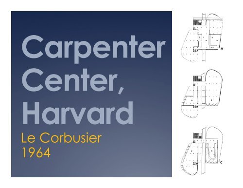
<strong>Carpenter</strong><br />
<strong>Center</strong>,<br />
Harvard<br />
<strong>Le</strong> <strong>Corbusier</strong><br />
1964
A building on a<br />
shortcut between<br />
Quincy and Prescott<br />
Streets
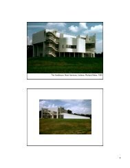
The <strong>Carpenter</strong> <strong>Center</strong><br />
<strong>for</strong> <strong>Visual</strong> <strong>Arts</strong><br />
Located at Harvard University, the<br />
<strong>Carpenter</strong> <strong>Center</strong> is <strong>Le</strong> <strong>Corbusier</strong>’s<br />
only project in the United States.<br />
The firm of Jose Luis Sert was the<br />
local coordinating <strong>architect</strong>. Sert<br />
was Dean of the Harvard GSD at<br />
the time, and was influential in<br />
securing the commission <strong>for</strong><br />
Corbu.
Corbu proposed that the project<br />
would have all of his elements of<br />
<strong>architect</strong>ure included.<br />
Ramp<br />
Piloti<br />
Free plan<br />
Bris Solei<br />
Roof Garden<br />
The ramp is both an access<br />
through the building to the<br />
neighborhood beyond Harvard<br />
and is the path to the front door
One answer to two problems<br />
Another concern Corbu had<br />
was the visual weight of the<br />
ramp.<br />
Engineers were planning to<br />
place a beam below the ramp<br />
to carry it from piloti to piloti.<br />
To address Corbu’s concern<br />
that a beam below made the<br />
ramp seem to heavy, the<br />
engineers took advantage of<br />
the monolithic nature of<br />
concrete and put the beam<br />
above the slab to carry it…<br />
where it also acts as a guard<br />
rail!
Problem...<br />
Slabs supported on piloti’s<br />
challenged the structural<br />
engineers working with Sert.<br />
The floor loads of the studio’s<br />
above were too high <strong>for</strong> a simple<br />
flat plate… Shear <strong>for</strong>ces indicated<br />
that drop panels would be<br />
necessary at each column head.<br />
Corbu said no, nothing can<br />
interrupt the piloti meeting the<br />
slab.
This is where the<br />
magic of cast in<br />
place concrete<br />
comes in.<br />
To resist shear at<br />
the piloti head,<br />
additonal<br />
material and<br />
steel is needed.<br />
This is usually<br />
added below<br />
the slab to <strong>for</strong>m<br />
a shear head or<br />
drop panel.<br />
Sert’s engineers<br />
proposed<br />
placing the shear<br />
heads above the<br />
slab instead!
Another problem...<br />
Usually shear<br />
heads never go<br />
above the slab<br />
because …<br />
people would trip<br />
on them!<br />
But Corbu’s<br />
clarity of vision<br />
about the piloti<br />
and slab was<br />
also challenging<br />
the mechanical<br />
engineers…. He<br />
would accept no<br />
ductwork visible<br />
in the space!
Problem + Problem = solution!<br />
The structural<br />
and mechanical<br />
engineers were in<br />
different firms,<br />
not in direct<br />
communication,<br />
they could only<br />
see their own<br />
problem…Corbu!<br />
Sert’s <strong>architect</strong>s<br />
combined both<br />
problems and<br />
found the<br />
solution!
Air filled floors<br />
Supply air would be carried<br />
through a network of small voids<br />
beneath a floor slab poured on top<br />
of the structural slab!<br />
This Air Floor would cover up the<br />
shear heads so no tripping, no<br />
projections below the slab, no<br />
ducts…everybodies concerns are<br />
addressed.<br />
The Air Floor product was ‘+’<br />
shaped plastic vaults set on the<br />
floor slab and connected to supply<br />
air ducts in the walls.<br />
Where supply air was needed <strong>for</strong> in<br />
the room distribution, a slot was cut<br />
through the topping into the Air<br />
Floor to release supply air.
Traveling in Boston, Corbu thought a higher quality of concrete was possible<br />
here than in France. The details of the bris solei and ondulatories challenged<br />
the <strong>for</strong>m builders, concrete placers to execute the very tall, very thin vertical<br />
elements.
The quality of the finished<br />
project is very high, one of<br />
the best concrete<br />
buildings in the U.S.<br />
This due in a large part to<br />
the quality of the<br />
<strong>for</strong>mwork, built by<br />
tradesman from the ship<br />
building industry in Boston!<br />
Who else could build<br />
wood structure precisely,<br />
without leaks around<br />
curves and detailed<br />
elements?
Not many flaws exist on<br />
this project.<br />
One of the few, this<br />
honeycomb at the joint<br />
between a floor slab and<br />
a vertical face of the bris<br />
solei may have been<br />
caused by a <strong>for</strong>m leak.<br />
Any <strong>for</strong>m leak will allow<br />
water and cement paste<br />
out of the <strong>for</strong>m, leaving a<br />
segregated mix area<br />
behind.
Here, the wall <strong>for</strong>ms deflected under the load of the<br />
concrete, and bowed out at the middle of each <strong>for</strong>m. A<br />
little more bracing may have prevented this.
Concrete<br />
Mullions<br />
Corbu used<br />
concrete to <strong>for</strong>m<br />
the mullions<br />
between glazed<br />
panels around the<br />
curved portions of<br />
the plan.<br />
These ondulatories<br />
were precast and<br />
set in place as the<br />
glazing was<br />
installed.
Structural<br />
handrails<br />
In many of Corbu’s<br />
projects using these<br />
ondulatories, the<br />
concrete was too thin<br />
and began to deflect,<br />
breaking the glazing.<br />
Here, and in other<br />
projects, a steel rail has<br />
been added to both<br />
brace the ondulatories<br />
and act as a guard rail,<br />
keeping people from<br />
walking through the<br />
glass!
Ondulatories &<br />
Aereatures<br />
The glazing between the<br />
ondulatories was not operable in<br />
most of <strong>Le</strong><strong>Corbusier</strong>’s projects.<br />
To provide <strong>for</strong> ventilation, Corbu<br />
designed pivoting opaque<br />
panels he called aereatures that<br />
could be opened to allow in air,<br />
keeping the glazing system a<br />
simple, inexpensive, fixed design.