HYL Solutions For Quality DRI Production In India - Tenova
HYL Solutions For Quality DRI Production In India - Tenova
HYL Solutions For Quality DRI Production In India - Tenova

Create successful ePaper yourself
Turn your PDF publications into a flip-book with our unique Google optimized e-Paper software.
<strong>HYL</strong> <strong>Solutions</strong> <strong>For</strong> <strong>Quality</strong><br />
<strong>DRI</strong> <strong>Production</strong> in <strong>In</strong>dia<br />
Steel & Metallurgy 3rd <strong>In</strong>ternational<br />
Conference on Raw Materials &<br />
Technology<br />
Bhubaneswar, Orissa, <strong>In</strong>dia<br />
July 2007
About Our New Name and Logo<br />
<strong>HYL</strong> Technologies became part of Techint<br />
Technologies in 2005<br />
Techint Technologies is now called<br />
<strong>Tenova</strong><br />
<strong>HYL</strong> is now <strong>Tenova</strong> <strong>HYL</strong>
Ironmaking Needs <strong>For</strong> <strong>In</strong>dia<br />
<strong>In</strong>dian <strong>DRI</strong> production is chiefly coal-based<br />
•Small plant sizes<br />
•Environmentally problematic<br />
•But low in capital requirements<br />
Gas pipelines will soon make natural gas<br />
available<br />
Coal is still more abundant, so a cleaner<br />
solution is needed for future growth<br />
Iron ore is abundant; value-added product<br />
is needed to increase revenues<br />
The merchant DR market is very large but<br />
HBI production requires added cost and<br />
higher volumes<br />
… what are the best options for <strong>In</strong>dia??
<strong>DRI</strong> vs. HBI<br />
Two different forms of the same<br />
product:<br />
• <strong>DRI</strong> is the traditional form, in<br />
either pellet or lump ore form<br />
• HBI is compressed <strong>DRI</strong><br />
Two different uses (theoretically) :<br />
• <strong>DRI</strong> is for onsite production and<br />
use in EAF meltshops<br />
• HBI is for commercial shipment<br />
to customers worldwide, usually<br />
by sea<br />
HBI is the form adopted for<br />
merchant sale of reduced iron, since<br />
it is deemed safer for shipping and<br />
handling
The Reality: World DR Shipments<br />
Shipments of product historically<br />
includes both <strong>DRI</strong> and HBI<br />
• Shipments tend to average 50%<br />
for either product form<br />
• Shipments by land or sea are<br />
also usually 50% for each<br />
If <strong>DRI</strong> can safely be shipped, then<br />
the cost of producing HBI has to be<br />
justified.<br />
Cost of producing HBI is $6-15 per<br />
ton higher than for <strong>DRI</strong>.
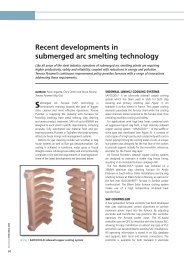
Market Scenario<br />
World HBI/<strong>DRI</strong> shipments for 2006<br />
14.56 M tons<br />
HBI<br />
46%<br />
<strong>DRI</strong><br />
54%<br />
Based on experience from <strong>HYL</strong> and<br />
other producers, <strong>DRI</strong> shipments are<br />
mainly characterized by the<br />
following target markets:<br />
• <strong>For</strong> internal use in mills with own<br />
DR plants.<br />
• <strong>For</strong> regional export - land<br />
transport.<br />
• Particular shipments from own<br />
plants with own harbors to other<br />
own plants with own harbors.<br />
• As merchant product from some<br />
plants.
Metallics for the EAF<br />
Onsite <strong>DRI</strong> production can solve or minimize reliance on fluctuating market<br />
conditions.<br />
Metallics have to be bought on the local and/or foreign market if not produced<br />
onsite.<br />
Until recently, gas-based <strong>DRI</strong> production was only available from 0.5 million<br />
tpy and higher capacity modules.<br />
• Advantage of higher quality <strong>DRI</strong> products<br />
• Disadvantage in capital cost compared to coal-based plants (in <strong>In</strong>dia)
A Technology Solution<br />
The <strong>HYL</strong> Process has always had independent reforming and reduction<br />
sections<br />
By eliminating the external reformer – the reforming, reduction and<br />
carburization occurs within the shaft furnace<br />
This concept, called the ZR Process, has operated succesfully since 1998
Smaller, More Efficient Plant & Process<br />
The <strong>HYL</strong> ZR Process plant is much smaller than a conventional DR plant<br />
• High pressure operation requires smaller equipment<br />
• No reformer means significant savings<br />
• Efficiencies in fabrication and construction further reduce plant investment<br />
cost<br />
• Equipment and structure redesign made possible the <strong>HYL</strong> Micro-Module
<strong>HYL</strong> Micro-Module DR Plant<br />
200,000 mtpy plant size<br />
• Advanced <strong>HYL</strong> ZR technology<br />
• Low investment cost<br />
• High quality, high carbon <strong>DRI</strong>
Why a Micro-Module?<br />
<strong>For</strong> steel mills, a <strong>DRI</strong> integrated facility presents the following advantages:<br />
• <strong>DRI</strong> would be available on site<br />
• Liquid Steel quality is improved by using <strong>DRI</strong><br />
• <strong>DRI</strong> production rate can be tailored to meet the requirements of the<br />
Minimill<br />
<strong>For</strong> merchant suppliers:<br />
• High carbon <strong>DRI</strong> can be produced at lower capex and operating expense<br />
than for HBI<br />
• High carbon <strong>DRI</strong> can be safely transported to steel mills<br />
• Small plants can more easily satisfy local markets
Why a Micro-Module?<br />
Simple and compact plant:<br />
• Low maintenance cost<br />
• Minimum manpower<br />
requirements<br />
Easy operation<br />
Low operating cost:<br />
• Flexibility in processing<br />
wide range of cheaper<br />
iron ores (pellets/lumps)<br />
Uniform and flexible high <strong>DRI</strong><br />
quality adjusted to meet any steel<br />
specification:<br />
≥ 93% metallization & 2-5%<br />
Carbon<br />
The total absence of residual<br />
elements makes it ideal for the<br />
EAF:<br />
To dilute the residuals found in<br />
scrap.<br />
<strong>For</strong> up to 100% of the furnace<br />
charge.<br />
It is also a metallic charge for<br />
blast furnaces and foundries.
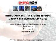
<strong>HYL</strong> ZR Process Description<br />
The <strong>HYL</strong> ZR process includes the<br />
following features which, when<br />
combined, eliminate<br />
the need for a reformer:<br />
• Partial combustion of the<br />
reducing gas.<br />
CO 2<br />
• “<strong>In</strong> situ” reforming in the lower<br />
part of the reactor’s reduction<br />
zone.<br />
• Adjustable composition of the<br />
reducing gas.<br />
Natural<br />
Gas<br />
Humidifier<br />
Fuel<br />
H 2 O<br />
Oxygen<br />
Iron<br />
Ore<br />
<strong>DRI</strong>
Micro-Module Process Scheme<br />
PG<br />
Compressor<br />
NG<br />
CO 2<br />
H 2 O<br />
Humidifier<br />
Heat<br />
Recuperator<br />
Iron Ore<br />
PG Heater<br />
Fuel<br />
Oxygen<br />
<strong>DRI</strong><br />
<strong>HYL</strong><br />
Reactor<br />
Quench<br />
Tower<br />
<strong>In</strong>-situ <strong>In</strong> situ Reforming<br />
CH4 + H2O CO + 3H2 CH4 + CO2 2CO + 2H2 Reduction<br />
Fe2O3 +3CO 2Fe Fe° + 3CO2 Fe2O3 +3H2 2Fe Fe° + 3H2O 3Fe° + CH 4<br />
Carburization<br />
Fe 3C+ 2H2
Basis of Design<br />
Product: Cold <strong>DRI</strong><br />
Metallization: 93%<br />
Carbon: 3.5%<br />
Hourly nominal capacity: 26 t /hr<br />
Annual Capacity 200,000 t /year<br />
Operating hours per year: 7,800
Expected Consumption Figures<br />
Product Type<br />
Cold <strong>DRI</strong><br />
Metallization ≥ 93%<br />
Carbon 3.50%<br />
Item unit<br />
Specific<br />
Consumption<br />
Iron ore (t/t) 1.38<br />
Natural gas (Gcal/t) 2.25<br />
Electricity (kWh/t) 90<br />
Oxygen (Nm 3 /t) 60<br />
Water (m 3 /t) 1.0<br />
Nitrogen (Nm 3 /t) 14<br />
Labour (m-m/t) 0.15<br />
Maintenance & supplies ($US/t) 3.0<br />
Others ($US/t) 0.4
Plant Concept & Battery Limits<br />
Utilities<br />
Nat.Gas, Oxygen, Nitrogen,<br />
Electricity, <strong>In</strong>dustrial water,<br />
Potable water<br />
DR Plant Boundary<br />
DR Plant Boundary<br />
Reduction circuit Raw Material Handling<br />
Reactor<br />
Cooling circuit<br />
Iron Ore Pellet Stockyard<br />
Product Handling<br />
Meltshop
<strong>HYL</strong> Micro-Module: Plant Layout<br />
52 m.<br />
67000<br />
SULPHURIC<br />
ACID ADDITION<br />
SYSTEM<br />
WS 546-U<br />
PCW PUMP<br />
CWS<br />
533-J2<br />
PCW PUMP<br />
C WS 533-J1<br />
RACK<br />
C<br />
SETTLING POND<br />
WS 544-G1/2<br />
PCW HOT WELL<br />
WS 339-G<br />
CLARIFIER<br />
WS 545-G<br />
C<br />
WATER FILTERING<br />
SOFTENING<br />
C<br />
WS 549-U<br />
C SYSTEM<br />
WS 553-U CO 333-E<br />
ECW PUMPS L.P.<br />
WS 535-J<br />
OVERFLOWING<br />
PUMP INSTRUMENT<br />
WS 540-J<br />
AIR DRYER<br />
CUT<br />
453-U1/2<br />
AIR STORAGE TANK<br />
C UT 456-F<br />
AIR COMPRESSOR<br />
C UT 451-J<br />
QUENCHING<br />
COOLING WATER<br />
PUMPS<br />
WS 536-J1/2<br />
ECW PUMPS<br />
SELECTED<br />
SERVICES<br />
WS 546-J1/2<br />
FILTERED WATER<br />
PUMPS<br />
WS 549-U<br />
CHEMICAL ADDING<br />
SYSTEM<br />
WS 522-U<br />
EQUIPMENT/QUENCHING COOLING TOWER<br />
WS 547-U<br />
C<br />
PROCESS GAS<br />
COMPRESSOR<br />
PG 436-J<br />
70 90000 m.<br />
CO 350-J<br />
NATURAL GAS<br />
K.O DRUM<br />
C RG 611-F<br />
INSTRUMENT AIR<br />
K.O. DRUM<br />
C UT 454-F<br />
NITROGEN<br />
C STORAGE TANK<br />
UT 429-F<br />
CO 331-J<br />
CO 318-J<br />
CO 317-F<br />
CO 349-F<br />
CO 336-C<br />
W.C.<br />
SWITCH GEAR<br />
FIRST LEVEL<br />
CO 323-E<br />
PROCESS GAS<br />
CCOMP.<br />
AFTERCOOLER<br />
PG 671-F<br />
TRANSFORMERS<br />
(SECOND LEVEL)<br />
CO 341-F<br />
CONTROL ROOM<br />
CO 320-C<br />
ROOM OF<br />
UPS<br />
CO 322-J<br />
CO 341-C<br />
OFFICE<br />
KITCHEN<br />
C<br />
CO 324-E<br />
CO 338-G<br />
CO 337-G<br />
CO 327-G<br />
HUMIDIFIER<br />
PG 622-E<br />
PROCESS GAS<br />
CQUENCH<br />
TOWER<br />
PG 231-E<br />
CO 336-J<br />
COOLING<br />
C GAS QUENCH<br />
TOWER CG 433-E<br />
CO 316-C<br />
CO 348-B CO 325-F<br />
CO 325-J<br />
CO 313-F CO 315-C<br />
RACK<br />
C<br />
HUMIDIFIER<br />
WATER PUMPS<br />
PG 631-J 1/2<br />
C PROCESS<br />
GAS<br />
HEATER<br />
PG 302-B<br />
REACTOR<br />
C RE 221-D<br />
<strong>DRI</strong> CONVEYOR
Reactor Charging & Tower<br />
EL. 4.400<br />
C<br />
Simplified reactor tower arrangement<br />
consisting of single-leg discharge<br />
system and small reactor of 2.5 m ID.<br />
CONVEYOR TO<br />
IRON ORE BIN<br />
11^<br />
EL. 65.890<br />
C<br />
C<br />
M.R.<br />
M.R.<br />
M.R.<br />
M.R.<br />
C<br />
C<br />
B A B A<br />
C REACTOR<br />
TOWER<br />
C<br />
A B<br />
EL. 17.885<br />
C<br />
N.P.T. 0.000
High-C <strong>DRI</strong> vs. HBI <strong>Production</strong> Costs<br />
Metallization %<br />
Carbon %<br />
High-Carbon <strong>DRI</strong> vs. HBI <strong>Production</strong> Cost Analysis<br />
Total <strong>DRI</strong>/Saleable ratio 1.054<br />
based on published data<br />
1.016<br />
Price Consump. Cost Consump. Cost<br />
Unit<br />
US$/unit<br />
ENERGIRON-ZR<br />
High-Carbon <strong>DRI</strong><br />
94%<br />
4.0%<br />
Unit/t Saleable<br />
<strong>DRI</strong><br />
US$/t<br />
Saleable <strong>DRI</strong><br />
Unit/t<br />
Saleable HBI<br />
US$/t<br />
Saleable HBI<br />
DR Plant<br />
Iron ore pellets t 80.00 1.45 116.00 1.47 117.87<br />
Lump ore t 0.00 0.00 0.00 0.00 0.00<br />
Natural gas Gcal 3.00 2.44 7.33 2.40 7.19<br />
Electricity kWh 0.035 121 4.24 117 4.09<br />
Oxygen kWh 0.042 included 0.00 12.2 0.51<br />
Water m 3<br />
1.60 1.21 1.94 1.55 2.48<br />
Other consumables US$ 1.14 1.70<br />
Maintenance US$ 3.3 7.1<br />
Labour m-h 8.00 0.12 0.95 0.15 1.20<br />
Capital cost difference US$ 4.20<br />
Total Saleable <strong>DRI</strong>/HBI cost FOB US$/t 134.87 146.36<br />
Transport-<strong>In</strong>surance cost diff. US$/t 3.00<br />
<strong>In</strong>cluding transport losses CIF US$/t 2% losses 140.63 0.5% losses 147.09<br />
Note: All Consumption figures are affected by the ratio of Total <strong>DRI</strong>/Saleable Product<br />
Conventional<br />
HBI Plant<br />
93%<br />
1.5%
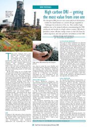
High-Carbon <strong>DRI</strong><br />
100*Combined Carbon/Total Carbon<br />
Combined Carbon (cementite or iron carbide - Fe3C) in<br />
Energiron High Carbide Iron<br />
100<br />
95<br />
90<br />
85<br />
80<br />
75<br />
70<br />
2 3 4 5 6 7<br />
% Total Carbon in <strong>DRI</strong><br />
A <strong>DRI</strong> with 4% Carbon contains more than 50% of<br />
Fe3C. The high percentage of Fe3C in the <strong>DRI</strong> of the 4M<br />
plant makes the product very stable.<br />
<strong>DRI</strong> Analysis – 4M Plant:<br />
Metallisation 94%<br />
Carbon 4%<br />
Fe° 83.0%<br />
Fe Total 88.3%<br />
Fe 3 C 55.1%<br />
Gangue 6.2%<br />
Most of the Carbon in the <strong>DRI</strong> is present as Fe3C, for a Carbon content of 4% approx. 95% of it is<br />
present as Fe3C. Every 1% of combined Carbon corresponds to<br />
13.5% of Fe3C.
Effect of High Carbon<br />
High carbon content in <strong>DRI</strong>, especially in chemically combined form (iron<br />
carbide) has significant advantages:<br />
• <strong>For</strong> steelmaking, it provides a source of chemical energy, reducing<br />
steelmaking costs and improving furnace yields<br />
• As a rule of thumb each 1% C in the <strong>DRI</strong> reduces power needs by about 30<br />
kWh/t liquid steel and the tap-to-tap time by about 2.5 min./heat.<br />
• It increases product quality<br />
• It is more stable than conventional <strong>DRI</strong>, making it easier to store and<br />
transport
High Carbide Iron vs. conventional <strong>DRI</strong><br />
<strong>In</strong> general, High Carbide Iron is more stable than conventional <strong>DRI</strong>. This has<br />
been proven through specific tests.<br />
LTS O2/TON HR<br />
6<br />
5<br />
4<br />
3<br />
2<br />
1<br />
0<br />
REACTIVITY OF <strong>DRI</strong> IN CONTACT WITH AIR<br />
<strong>HYL</strong> <strong>DRI</strong> Characteristics:<br />
<strong>DRI</strong> -ZR<br />
Mtz. = 94%, C = 4% (> 90% as Fe3C)<br />
<strong>DRI</strong> -w/Reformer<br />
Mtz. = 94%, C = 2%<br />
0 0.5 1 1.5 2<br />
TIME (DAYS)<br />
<strong>HYL</strong> ZR <strong>HYL</strong> III
High Carbide Iron vs. conventional <strong>DRI</strong><br />
<strong>DRI</strong> samples from Ternium Hylsa 3M5 plant before and after conversion to ZR<br />
Scheme for high carbon <strong>DRI</strong>. Note samples before were 2% - what others<br />
consider to be “high carbon”.<br />
LTS O2/TON HR<br />
60<br />
50<br />
40<br />
30<br />
20<br />
10<br />
0<br />
REACTIVITY OF <strong>DRI</strong> IN CONTACT WITH AIR+WATER<br />
<strong>HYL</strong> <strong>DRI</strong> Characteristics:<br />
<strong>DRI</strong> -ZR<br />
Mtz. = 94%, C = 4% (> 90% as Fe3C)<br />
<strong>DRI</strong> -w/Reformer<br />
Mtz. = 94%, C = 2%<br />
0 0.5 1 1.5 2<br />
TIME (DAYS)<br />
<strong>HYL</strong> ZR <strong>HYL</strong> III
High Carbide Iron vs. conventional <strong>DRI</strong><br />
These test results with salty water are of relevance due to the low risks for<br />
High Carbide <strong>DRI</strong> overseas transportation.<br />
Lts O2/Ton-Hr<br />
70<br />
60<br />
50<br />
40<br />
30<br />
20<br />
10<br />
0<br />
REACTIVITY OF <strong>DRI</strong> IN CONTACT WITH<br />
SALTY WATER + AIR<br />
<strong>HYL</strong> ZR Salty<br />
Water+Air<br />
<strong>HYL</strong> III<br />
w/Reformer<br />
Salty<br />
Water+Air<br />
0 2 4 6 8 10 12<br />
Time (Hrs)
<strong>HYL</strong> Micro-Module Supply<br />
Electrotherm <strong>In</strong>dia Ltd is the exclusive supplier of the <strong>HYL</strong> Micro-Module<br />
• Joint development of redesigned engineering<br />
• Markets and supplies the Micro-Modules, in a capacity range of 200,000 –<br />
400,000 mtpy<br />
• As EPC Contractor, completes the projects on turnkey basis
Additional Electrotherm Synergy<br />
ET also supplies electric arc and induction furnaces and other steel plant<br />
equipment like Metal Refining Konverters (MRK), DC Plasma Ladle Refining<br />
Furnaces, etc.<br />
Can design and install complete “mini” integrated plants based on <strong>DRI</strong> and<br />
electric furnaces (MF <strong>In</strong>duction Furnaces, Channel <strong>In</strong>duction Furnaces,<br />
Electric Arc Furnaces).<br />
Over 12 million tonnes of steel is produced on ET-supplied <strong>In</strong>duction<br />
Furnaces.
First Efforts<br />
The first Micro-Module has been contracted for Al Nasser <strong>In</strong>dustrial<br />
Enterprises of Abu Dhabi, UAE<br />
• 200,000 tonnes/year<br />
• Basic Engineering completed, Detailed Engineering in progress<br />
• Site Mobilisation started<br />
• Startup during 2008
<strong>HYL</strong> ZR Process<br />
Alternative Configurations
<strong>HYL</strong> ZR Plants: Module Sizes<br />
<strong>HYL</strong> currently offers the following standard single-reactor modules:<br />
• Micro-Module: 200,000 tpy<br />
• Mini-Module: 500,000 tpy<br />
• Midi-Module: 800,000 tpy<br />
• Mega-Module: 1,200,000 tpy<br />
• Macro-Module: 1,600,000 tpy
Flexibility for Other Reducing Gases<br />
Conventional reformed gas<br />
Coke oven gas<br />
Gases from coal gasification processes<br />
Gases from hydrocarbon gasification<br />
Gases from smelter gasifiers<br />
Hydrogen<br />
Others…
Use of Syngas from Coal Gasification<br />
Coal Oxygen Iron Ore<br />
Coal Gasifier<br />
CxHy + O 2 = CO 2 + H 2O O +<br />
H2 + CO<br />
<strong>HYL</strong> DR Plant<br />
Fe 2O3 + 3H2 = 2Fe + 3H2O Fe2O3 + 3CO = 2Fe + 3CO 2<br />
<strong>DRI</strong>
<strong>HYL</strong> Process Scheme for Syngas<br />
Coal<br />
Gasifier<br />
WHB &<br />
Cooling<br />
Gas<br />
Conditioning<br />
Cooler<br />
CO 2<br />
Removal<br />
Gas conditioning<br />
Sulphur<br />
removal Plant<br />
P. Gas<br />
Compressor<br />
CO 2<br />
Expander or<br />
compressor<br />
H 2O<br />
Humidifier<br />
Fuel<br />
<strong>HYL</strong> Module<br />
PG Heater<br />
Oxygen<br />
Iron<br />
Ore<br />
<strong>DRI</strong><br />
DR<br />
Reactor
Plant configuration with Syngas from coal gasification<br />
Lurgi Coal<br />
Gasifier<br />
WHB &<br />
Cooling<br />
Gas<br />
Conditioning<br />
(Shifter)<br />
Cooler<br />
Stream 1 2 3 4<br />
Concept Syngas Decarbonated<br />
Syngas<br />
Sulphur<br />
removal Plant<br />
1 2<br />
CO 2<br />
Absorber<br />
Syngas<br />
to DR<br />
P. Gas<br />
Compressor<br />
CO 2<br />
Absorber<br />
Expander<br />
Decarbonated<br />
Recycling Gas<br />
Flow-Nm 3 /t 849 632 632 1,126<br />
Temp.-°C 40 42 15 42<br />
Press.-kg/cm 2 g 27.5 27.0 8.5 7.7<br />
Energy-GCal/t 2.21 2.21 2.21 ---<br />
H 2 55 55 49<br />
CO 25 25 16<br />
CO 2 2 2 12<br />
CH 4 16 16 17<br />
N 2 1 1 5<br />
H 2O 1 1 1<br />
3<br />
4<br />
H 2O<br />
Humidifier<br />
Fuel<br />
PG Heater<br />
Iron Ore<br />
<strong>DRI</strong><br />
DR<br />
Reactor
Syngas requirements for <strong>DRI</strong> <strong>Production</strong><br />
Comparative Reduction Gas Analysis<br />
Item (%<br />
volume)<br />
Syngas<br />
Make-up<br />
Syngas to<br />
Reactor<br />
Reduc. gas in<br />
<strong>HYL</strong> ZR Scheme<br />
using natural<br />
gas with 100% insitu<br />
reforming<br />
H 2 39 54 50<br />
CO 24 20 15<br />
CH 4 + C nH m 10 18 25<br />
CO 2 26 2 3<br />
H 2O 0.3 4 4<br />
(H 2+CO)/<br />
(CO 2+H 2O) 13.3 9.3<br />
N 2 0.2 4 3<br />
Similarity of reducing gases at reactor inlet.<br />
There are no technological risks because of<br />
this similarity.<br />
Syngas<br />
Process<br />
+ Fuel<br />
9.5 GJ/t<br />
Pellets/Lump ore<br />
1,38 t<br />
DR - Plant<br />
<strong>DRI</strong><br />
1,0 t<br />
Tail Gas<br />
0 GJ/t
Consumption Figures<br />
Syngas from coal gasification – Lurgi gasifier<br />
Item ENERGIRON<br />
Unit Scheme<br />
<strong>DRI</strong> <strong>Quality</strong><br />
- Metallization ≥ 93%<br />
- Carbon ≥ 2.5%<br />
Gas quality H 2/CO<br />
Consumption Figures<br />
2.21<br />
- Syngas make-up Nm 3 /t <strong>DRI</strong> 632<br />
equivalent to: Gcal/t <strong>DRI</strong> 2.2<br />
- Iron ore t/t <strong>DRI</strong> 1.4<br />
- Electricity incl. Syngas expander kWh/t <strong>DRI</strong> 67<br />
- Electricity excl. Syngas expander kWh/t <strong>DRI</strong> 88<br />
- Oxygen (only for Lurgi-type gasifier,<br />
which presents CH 4)<br />
Nm 3 /t <strong>DRI</strong> 5<br />
- Water m 3 /t <strong>DRI</strong> 1.3<br />
- Nitrogen Nm 3 - Total Steam to integrated gasifier-<br />
/t <strong>DRI</strong> 12<br />
DR CO 2 removal plant (wich can be<br />
partly produced in the gasifier system)<br />
kg/t <strong>DRI</strong> 1000
Use of Syngas<br />
Synergy with coal gasification technologies<br />
Depending on particular applications, optional schemes, which can be<br />
incorporated, are:<br />
1. <strong>In</strong> plant electrical generation<br />
<strong>For</strong> high-pressure gasifiers, it is possible to install a turbo expander in the<br />
treated syngas stream before being fed to the DR module. This allow<br />
potential power savings of about 20-40 kWh/tonne of <strong>DRI</strong> (depending on<br />
gasifier technology), taking advantage of the gasifier high operating<br />
pressure.<br />
2. Carbon dioxide (CO 2 ) recovery<br />
<strong>For</strong> sale as by-product or selective disposal/conversion.
Most Suitable Technology for Using Syngas<br />
Comparing the basic <strong>HYL</strong> Process scheme to the one required for syngas<br />
from coal gasification, the following main aspects related to the <strong>HYL</strong> Process<br />
application can be easily noticed:<br />
General process scheme<br />
No major changes and innovations are required in the basic process<br />
scheme. The reduction section is incorporated as it is in typical <strong>HYL</strong> ZR<br />
plants.<br />
Synergy with the coal gasification unit, sharing common CO 2 removal plant<br />
components, by taking advantages of the <strong>HYL</strong> high operating pressure,<br />
chemical absorption and low CO 2 concentration to the DR plant.<br />
H 2 -rich gases use in DR plants<br />
Syngas is conditioned through shifting and/or CO 2 removal to properly adjust<br />
the H 2 /CO in the reducing gases to the <strong>HYL</strong> Process.<br />
Optimisation of Process syngas consumption<br />
Recycling of reducing gases, through CO 2 removal, minimizes syngas makeup.
Plant Tests<br />
Plant experience with Syngas<br />
<strong>HYL</strong> R & D has<br />
simulated, in the<br />
demonstration plant, the<br />
gas composition of typical<br />
Syngas, and a process<br />
scheme for using this gas<br />
has been developed.<br />
The reduction process is<br />
feasible for producing <strong>DRI</strong><br />
with 93-94% metallization<br />
and ~ 1.5% carbon.<br />
The reducing gas<br />
temperature at the reactor<br />
inlet about 950°C and the<br />
treated Syngas<br />
consumption (make–up)<br />
for PROCESS only is<br />
estimated to be about 625-<br />
650 Nm 3 /ton <strong>DRI</strong>.
Conclusions<br />
The <strong>HYL</strong> Micro-Module is a low cost, high quality option for small steel<br />
producers or merchant suppliers to produce high quality, High Carbide Iron.<br />
The independent operation of the <strong>HYL</strong> ZR Process has enabled this dramatic<br />
reduction in DR plant size, while maintaining quality and reliability.<br />
Through Electrotherm <strong>In</strong>dia Ltd., <strong>HYL</strong> can supply complete Micro-Module<br />
packages.<br />
<strong>HYL</strong> also offers ZR Plants with other reducing gas sources, depending on the<br />
specific market.<br />
<strong>For</strong> the <strong>In</strong>dian Subcontinent, a number of these options such as using Syngas<br />
are viable in addition to the Micro-Module.