Operating & Maintenance Instructions Dry ... - Roto Pumps Ltd.
Operating & Maintenance Instructions Dry ... - Roto Pumps Ltd.
Operating & Maintenance Instructions Dry ... - Roto Pumps Ltd.

Create successful ePaper yourself
Turn your PDF publications into a flip-book with our unique Google optimized e-Paper software.
®<br />
<strong>Operating</strong> & <strong>Maintenance</strong> <strong>Instructions</strong><br />
<strong>Dry</strong> Running Protection Device DRP-001<br />
<strong>Roto</strong> <strong>Pumps</strong> <strong>Ltd</strong>.<br />
<strong>Roto</strong> House, Noida Special Economic Zone<br />
Phase – II, Noida – 201305, Uttar Pradesh (India)<br />
Ph – 0120 3043901 TO 04, Fax – 0120 2562561<br />
Email – contact@rotopumps.com<br />
Website – www.rotopumps.com<br />
AD MANUAL NO:<br />
AD-50-001-00
DESIGN<br />
VARIANT<br />
TYPE<br />
PUMP SERIES<br />
SIZE<br />
DRY RUNNING PROTECTION<br />
DRP<br />
ISSUE NO : DRP 001<br />
CODIFICATION ISSUE DATE : 24.04.06<br />
DESCRIPTION 01 02 03 04 05 06 07 08 09<br />
DRY RUNNING PROTECTION D R P<br />
FIRST DESIGN 0<br />
DOMESTIC 0<br />
UK 1<br />
AUSTRALIA 2<br />
USA 3<br />
COMPLETE SYSTEM 1<br />
THERMO WELL ASSEMBLY 2<br />
THERMAL PROBE ASSEMBLY 3<br />
INDUSTRIAL D RANGE D<br />
INDUSTRIAL M RANGE M<br />
INDUSTRIAL L RANGE L<br />
INDUSTRIAL N RANGE N<br />
43 45 47 49 51 53 55 5 5<br />
50 52 54 56 58 60 62 64 66 68 70 72<br />
63 67 71<br />
01 02 03 04 05 06 07 08 09 10<br />
SAMPLE CODE D R P 0 0 1 D 5 5<br />
NOTE : THE ABOVE SAMPLE CODE REFERS TO DRY RUNNING PROTECTION DEVICE OF FIRST DESIGN<br />
FOR DOMESTIC MARKET, COMPLETE SYSTEM CONTAINING THE CONTROLLER AS WELL AS THERMO<br />
WELL AND RTD SENSOR. COMPATIBLE FOR RDAA 55 SIZE PUMP.
3<br />
4<br />
5<br />
2<br />
1<br />
®<br />
<strong>Operating</strong> & <strong>Maintenance</strong> <strong>Instructions</strong><br />
<strong>Dry</strong> Running Protection Device DRP-001<br />
AD MANUAL NO:<br />
AD-50-001-00<br />
9<br />
8<br />
7<br />
6<br />
10<br />
11
®<br />
<strong>Operating</strong> & <strong>Maintenance</strong> <strong>Instructions</strong><br />
<strong>Dry</strong> Running Protection Device DRP-001<br />
WARINING make sure that the power has<br />
been disconnected from the Temperature<br />
Controller prior to servicing.<br />
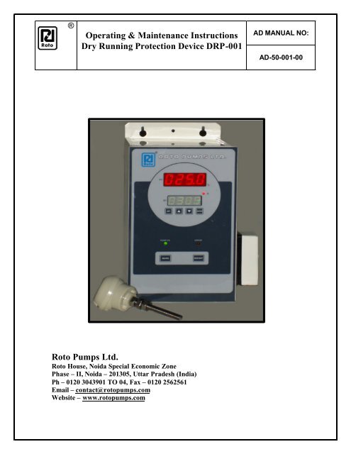
The <strong>Dry</strong> running protection, which is a device<br />
to protect the stator from dry running mainly,<br />
consists of three parts; the Temperature<br />
Controller (processor) with LED display, the<br />
Temperature Sensor (PT-100 RTD), and the<br />
Thermo Well.<br />
1. The Device functions as follows<br />
In the stator of the pump there is a<br />
Temperature Sensor. This sensor<br />
continuously measures the stator temperature<br />
which range from 0°C to 200°C. If the stator<br />
temperature rises above the programmed or<br />
specified cut-off temperature (about normal<br />
pumping temperature), which is set on the<br />
controller, there will be an optical or acoustic<br />
signal indication on the controller and will also<br />
switch the pump off immediately.<br />
2. Setting Cut-off the Temperature<br />
The cut off temperature value of the controller<br />
in normal conditions is easy to adjust.<br />
• Connect the input, output and RTD<br />
wires as per the terminal connections.<br />
• Press the MAINS button (1), the<br />
PUMP ON LED (2) would energize<br />
with an acoustic beep. When no key is<br />
pressed, the display at Process Value<br />
PV (3) shows the actual stator<br />
temperature.<br />
• Press SET button (4) for 2 seconds<br />
SET would be displayed at PV (3).<br />
Release the SET button (4), you are<br />
now in set mode<br />
• By pressing the buttons (5) and (6) the<br />
pump cut off temperature can raised<br />
or lowered to the desired settings.<br />
• Press ENTER button (7) the set value<br />
would be stored in the memory and<br />
AD MANUAL NO:<br />
AD-50-001-00<br />
the LED at (9) would illuminate. The<br />
Set Value (SV) (8) would be<br />
retained in the memory even if there<br />
is a power failure.<br />
• Press the RESTART button (11) to<br />
start the pump and the acoustic<br />
beep would stop.<br />
3. Selecting the Cut-off Temperature<br />
• Adjust the cut-off temperature up to<br />
150°C at the controller.<br />
• Start the pump.<br />
• When steady pumping is being<br />
obtained, a read out of the stator<br />
temperature will be displayed at PV<br />
(3) on the controller.<br />
• If this is accurate, taking into<br />
consideration the product and<br />
ambient temperatures, then the cutoff<br />
temperature can be set 5°C<br />
higher.<br />
4. Switching Functions<br />
With the temperature sensor connected and<br />
the operating voltage applied to the<br />
controller, the internal relay is energized.<br />
If the cut-off temperature is being exceeded<br />
or a short -circuit is occurring, the internal<br />
relay drops out and the pump would stop<br />
immediately.<br />
The pump would not start automatically<br />
unless the sensor temperature is lower than<br />
the set temperature.<br />
To restart the pumps again press the<br />
RESTART button (11).<br />
5. Safety Precautions<br />
If a temperature sensor is operated within a<br />
hazardous area there must be a special<br />
enclosure installed between the<br />
Temperature Controller and the<br />
Temperature Sensor (RTD).
®<br />
<strong>Operating</strong> & <strong>Maintenance</strong> <strong>Instructions</strong><br />
<strong>Dry</strong> Running Protection Device DRP-001<br />
The switching of inductive loads (contacts)<br />
may result a false reading from the Controller,<br />
or in complete malfunction of the Unit. Here,<br />
we recommended the wiring of a Surge<br />
Suppressor.<br />
6. Installations of Temperature Sensor and<br />
Controller.<br />
The Stator (2224), as displayed in Std.<br />
No.RN-10-242-01 sheet 1,2,3,4 and 5 is<br />
equipped with a Themo-well-head (3) and a<br />
Temperature Sensor (PT-100RTD), (1).<br />
The stator is delivered with a built-in Thermo<br />
Well (2). When installed on a ROTO Pump,<br />
this Thermo Well should be mounted on its<br />
inlet side.<br />
7. Technical Data<br />
- Microcontroller based double<br />
display.<br />
- Size: 72 x 72 x 110 mm<br />
- Panel cutout : 68 x 68<br />
- Supply: 110-230 V A.C., 50 Hz.<br />
( SMPS )<br />
- Measuring input for PT- 100<br />
RTD/3W (RTD Type)<br />
Temperature Sensor.<br />
Terminal Box Connections<br />
AD MANUAL NO:<br />
AD-50-001-00<br />
- Material of Construction:<br />
Platinum Upper 4 digit display in<br />
red colour indicates current<br />
process temperature value.<br />
- Lower 4 digit display in green<br />
colour indicates current set<br />
value<br />
- Led on the right side glows<br />
when the relay is on.<br />
- Range 0-200.0°C.<br />
- Output: 1 relay with 2 C/O, 230<br />
V A.C., 5 Amp. Contact.<br />
- Control action: TP / ON-OFF<br />
selectable.<br />
* Controller should not be more than<br />
10 meters from the temperature<br />
sensor.<br />
8. Terminal Box<br />
This illustration shows the electrical outline<br />
connection of a DRP-001 <strong>Dry</strong> Running<br />
Protection Device.<br />
MAINS CONTROL INPUT OUTPUT X SENSOR<br />
1 2 3 4 5 6 7 8 9 10 11 12<br />
L L N E L N<br />
230 VAC<br />
TO<br />
DIRECT<br />
ON LINE<br />
R W W<br />
230<br />
VAC<br />
110<br />
VAC<br />
L1 L2<br />
440 VAC<br />
STARTER<br />
SENSOR<br />
PT-100(RTD)