Flowserve Edward and Anchor/Darling Nuclear Application Valves
Flowserve Edward and Anchor/Darling Nuclear Application Valves
Flowserve Edward and Anchor/Darling Nuclear Application Valves

Create successful ePaper yourself
Turn your PDF publications into a flip-book with our unique Google optimized e-Paper software.
Experience In Motion<br />
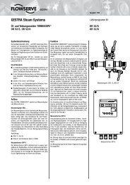
<strong>Edward</strong> <strong>and</strong> <strong>Anchor</strong>/<strong>Darling</strong><br />
<strong>Nuclear</strong> <strong>Application</strong> <strong>Valves</strong>
2<br />
We’ll Support You<br />
<strong>Flowserve</strong>’s Flow Control Division is dedicated to<br />
providing continuous aftermarket support to our<br />
nuclear customers. Safety-related valves <strong>and</strong> parts<br />
are supplied in accordance with ASME Section III<br />
<strong>and</strong> 10 CFR 50 Appendix B on a routine basis; <strong>and</strong><br />
more importantly, in support of refueling outages <strong>and</strong><br />
forced outages at nuclear generating stations.<br />
<strong>Flowserve</strong> engineers, with working knowledge of<br />
nuclear applications <strong>and</strong> requirements are available<br />
on a 24-hour basis to respond to phone calls from<br />
nuclear customers with critical outage <strong>and</strong> unforeseen<br />
forced outage help requirements. At <strong>Flowserve</strong>, we<br />
underst<strong>and</strong> the necessity of maintaining critical-path<br />
schedules!<br />
When you specify <strong>Flowserve</strong> nuclear safety-related<br />
valves, you can rest ensured that the ongoing support<br />
<strong>and</strong> technical backup you may need down the road<br />
will be available to you right now!<br />
<strong>Flowserve</strong>’s <strong>Edward</strong> <strong>and</strong> <strong>Anchor</strong>/<strong>Darling</strong> valves are<br />
manufactured exclusively at our Raleigh, North<br />
Carolina, operation. Of the various <strong>Flowserve</strong><br />
manufacturing facilities, the Flow Control Division’s<br />
Raleigh operation is a long-time holder of ASME<br />
Section III N <strong>and</strong> NPT stamps, as well as the National<br />
Board’s <strong>Nuclear</strong> Repair (NR) stamp.<br />
We maintain a quality assurance system in<br />
accordance with ASME Section III <strong>and</strong> 10 CFR 50<br />
Appendix B with controlled copies of our QA Manual<br />
available to nuclear customers. Non-destructive<br />
testing including radiography, liquid penetrant<br />
inspection, mag particle inspection, ultrasonic testing,<br />
PMI <strong>and</strong> mechanical property testing are performed<br />
in-house by ASNT/EN 473 qualified examiners <strong>and</strong><br />
inspection personnel. Design reports, seismic reports,<br />
environmental qualification reports <strong>and</strong> certified<br />
drawings are prepared by Raleigh’s engineering<br />
department. Additionally, <strong>Flowserve</strong>’s Flow Control<br />
Division offers dedication of commercial-grade<br />
items by qualified inspection personnel based on<br />
engineering-prescribed critical characteristics <strong>and</strong><br />
dedication methods.<br />
Specify <strong>Flowserve</strong> <strong>Edward</strong> <strong>and</strong> <strong>Anchor</strong>/<strong>Darling</strong><br />
valves for nuclear safety-related requirements to<br />
ensure strict adherence to applicable nuclear codes<br />
<strong>and</strong> st<strong>and</strong>ards, on-time delivery <strong>and</strong> continuing<br />
aftermarket parts support.<br />
<strong>Flowserve</strong> <strong>Edward</strong> <strong>and</strong> <strong>Anchor</strong>/<strong>Darling</strong> <strong>Valves</strong> • 1900 South Saunders Street, Raleigh, North Carolina 27603 • 1-800-225-6989 • 1-919-832-0525 • Fax 1-919-831-3369
Table of Contents<br />
<strong>Edward</strong> Figure Number Index 5<br />
<strong>Edward</strong> <strong>Valves</strong> Availability Chart 6<br />
<strong>Edward</strong> Description of Figure Number System 8<br />
<strong>Anchor</strong>/<strong>Darling</strong> Figure Number Index 10<br />
<strong>Anchor</strong>/<strong>Darling</strong> <strong>Valves</strong> Availability Chart 11<br />
<strong>Anchor</strong>/<strong>Darling</strong> Description of Figure Number System 14<br />
High Performance for Critical Service 16<br />
A History of Firsts 19<br />
<strong>Edward</strong> <strong>and</strong> <strong>Anchor</strong>/<strong>Darling</strong> <strong>Valves</strong> Available for <strong>Nuclear</strong> Service 20<br />
<strong>Edward</strong> Forged <strong>and</strong> Cast Steel <strong>Valves</strong> for <strong>Nuclear</strong> Service 21<br />
Checklist of Customer Information Required<br />
for <strong>Nuclear</strong> Valve Proposals 22<br />
<strong>Flowserve</strong> <strong>Edward</strong> Stored Energy Actuator 22<br />
Gas-Hydraulic Actuators for Fail-Safe Isolation <strong>Valves</strong> 23<br />
Main Steam <strong>and</strong> Main Feedwater Isolation <strong>Valves</strong> 24<br />
<strong>Edward</strong> Gate <strong>Valves</strong> 25<br />
Features <strong>and</strong> Description of <strong>Edward</strong> Equiwedge Gate <strong>Valves</strong> 26<br />
Parts Specification List for <strong>Edward</strong> Gate <strong>Valves</strong> 27<br />
Features <strong>and</strong> Description of <strong>Edward</strong> Equiwedge Gate <strong>Valves</strong> 28<br />
Center Cavity Overpressurization 28<br />
<strong>Anchor</strong>/<strong>Darling</strong> Gate <strong>Valves</strong> 35<br />
Features <strong>and</strong> Description of <strong>Anchor</strong>/<strong>Darling</strong><br />
800 Series Gate <strong>Valves</strong> 36<br />
Parts Specification List for <strong>Anchor</strong>/<strong>Darling</strong><br />
800 Series Gate <strong>Valves</strong> 37<br />
Features <strong>and</strong> Description of<br />
1888 Series Double-Disc Gate <strong>Valves</strong> 39<br />
Parts Specification List for <strong>Anchor</strong>/<strong>Darling</strong><br />
1888 Series Double-Disc Gate <strong>Valves</strong> 40<br />
Features <strong>and</strong> Description of Double-Disc Gate <strong>Valves</strong> 42<br />
Parts Specification List for Double-Disc Gate <strong>Valves</strong> 43<br />
Features <strong>and</strong> Description of <strong>Anchor</strong>/<strong>Darling</strong><br />
Flex-Wedge Gate <strong>Valves</strong> 49<br />
Parts Specification List for <strong>Anchor</strong>/<strong>Darling</strong><br />
Flex-Wedge Gate <strong>Valves</strong> 50<br />
<strong>Edward</strong> Globe <strong>and</strong> Stop-Check <strong>Valves</strong> 57<br />
Features <strong>and</strong> Description of <strong>Edward</strong> Bolted Bonnet<br />
Globe <strong>Valves</strong> 58<br />
Parts Specification List for <strong>Edward</strong><br />
Bolted Bonnet Globe <strong>Valves</strong> 59<br />
Features <strong>and</strong> Description of <strong>Edward</strong><br />
Univalve Globe <strong>Valves</strong> 62<br />
Parts Specification List for <strong>Edward</strong> Univalve <strong>Valves</strong> 63<br />
Features <strong>and</strong> Description of <strong>Edward</strong><br />
Hermavalve Hermetically Sealed <strong>Valves</strong> 68<br />
Parts Specification List for <strong>Edward</strong> Hermavalve 70<br />
Features <strong>and</strong> Description of <strong>Edward</strong> Stop-Check <strong>Valves</strong> 72<br />
Parts Specification List for <strong>Edward</strong> Globe <strong>Valves</strong>,<br />
Stop-Check <strong>and</strong> Piston Lift Check 73<br />
flowserve.com<br />
Features <strong>and</strong> Description of <strong>Edward</strong><br />
Flite-Flow Globe <strong>Valves</strong> 74<br />
Special <strong>Application</strong> <strong>Valves</strong> 75<br />
<strong>Anchor</strong>/<strong>Darling</strong> Globe <strong>Valves</strong> 89<br />
Features <strong>and</strong> Description of <strong>Anchor</strong>/<strong>Darling</strong><br />
800 Series Globe <strong>Valves</strong> 90<br />
Parts Specification List for <strong>Anchor</strong>/<strong>Darling</strong><br />
800 Series Globe <strong>Valves</strong> 91<br />
Features <strong>and</strong> Description of 1878 Series Globe Valve 94<br />
Parts Specification List for <strong>Anchor</strong>/<strong>Darling</strong><br />
1878 Series Globe <strong>Valves</strong> 95<br />
Features <strong>and</strong> Description of <strong>Flowserve</strong><br />
<strong>Anchor</strong>/<strong>Darling</strong> Globe <strong>Valves</strong> 100<br />
Custom-Designed Plugs 101<br />
Power-Actuated Globe <strong>Valves</strong> 101<br />
Parts Specification List for <strong>Anchor</strong>/<strong>Darling</strong><br />
Globe <strong>Valves</strong> 102<br />
<strong>Edward</strong> Check <strong>Valves</strong> 109<br />
Controlled Closure Check Valve 113<br />
Features <strong>and</strong> Description of <strong>Flowserve</strong> <strong>Edward</strong> Check <strong>Valves</strong> 114<br />
Features <strong>and</strong> Description of <strong>Flowserve</strong> <strong>Edward</strong> One-Piece<br />
Tilting-Disc Check <strong>Valves</strong> 115<br />
Parts Specification List for <strong>Edward</strong><br />
One-Piece Tilting-Disc Check Valve 116<br />
<strong>Anchor</strong>/<strong>Darling</strong> Check <strong>Valves</strong> 127<br />
Features <strong>and</strong> Description of 800 <strong>and</strong> 1878 Series<br />
Piston Check <strong>Valves</strong> 129<br />
Parts Specification List for <strong>Anchor</strong>/<strong>Darling</strong> 800 <strong>and</strong><br />
1878 Piston Check <strong>Valves</strong> 130<br />
Features <strong>and</strong> Description of 1878 Series Swing-Check <strong>Valves</strong> 134<br />
Parts Specification List for <strong>Anchor</strong>/<strong>Darling</strong><br />
1878 Swing-Check <strong>Valves</strong> 135<br />
Features <strong>and</strong> Description of <strong>Anchor</strong>/<strong>Darling</strong><br />
Check <strong>Valves</strong> 138<br />
Parts Specification List for <strong>Flowserve</strong> <strong>Anchor</strong>/<strong>Darling</strong><br />
Tilting-Disc Check <strong>Valves</strong> 140<br />
Parts Specification List for <strong>Flowserve</strong> <strong>Anchor</strong>/<strong>Darling</strong><br />
Swing Check <strong>Valves</strong> 141<br />
Parts Specification List for <strong>Flowserve</strong> <strong>Anchor</strong>/<strong>Darling</strong><br />
Lift Check Valve 142<br />
<strong>Anchor</strong>/<strong>Darling</strong> Ball <strong>Valves</strong> 153<br />
Features <strong>and</strong> Description of <strong>Flowserve</strong> <strong>Anchor</strong>/<strong>Darling</strong><br />
Ball <strong>Valves</strong> 154<br />
Parts Specification List for <strong>Anchor</strong>/<strong>Darling</strong> Ball <strong>Valves</strong> 155<br />
<strong>Flowserve</strong> <strong>Edward</strong> <strong>and</strong> <strong>Anchor</strong>/<strong>Darling</strong> <strong>Valves</strong> • 1900 South Saunders Street, Raleigh, North Carolina 27603 • 1-800-225-6989 • 1-919-832-0525 • Fax 1-919-831-3369<br />
3
<strong>Anchor</strong>/<strong>Darling</strong> Butterfly <strong>Valves</strong> 175<br />
Features <strong>and</strong> Description of <strong>Flowserve</strong> <strong>Anchor</strong>/<strong>Darling</strong><br />
Butterfly <strong>Valves</strong> 176<br />
Approximate Weights by Valve Design 177<br />
St<strong>and</strong>ard Materials of Construction 177<br />
Performance Characteristics 179<br />
Special <strong>Application</strong>s Valve 189<br />
Controlled Closure Check Valve 191<br />
Excess Flow Check <strong>Valves</strong> 192<br />
Vacuum Breaker <strong>Valves</strong> 194<br />
Accessories/Actuators 195<br />
Accessories 196<br />
Accessories – Cast <strong>and</strong> Forged Steel 197<br />
Actuators – Forged <strong>and</strong> Cast Steel 199<br />
Required Information for Motor Actuators 200<br />
Tables <strong>and</strong> Charts 201<br />
Material Chemical Analysis (ASME or ASTM) 202<br />
ASME B16.34 – 2009 Pressure/Temperature Ratings 203<br />
Technical Information 239<br />
1. Stop <strong>and</strong> Check Valve <strong>Application</strong>s Guide 241<br />
1.1 Stop Valve <strong>Application</strong>s 241<br />
1.1.1 Stop Valve Types <strong>and</strong> Typical Uses 241<br />
1.1.2 Throttling Characteristics of <strong>Edward</strong> Stop <strong>Valves</strong> 242<br />
1.1.3 Stop Valve Actuators <strong>and</strong> Accessories 243<br />
1.1.4 By-Passes <strong>and</strong> Drains 244<br />
1.1.5 Stop Valve <strong>Application</strong> Chart 245<br />
1.2 Check Valve <strong>Application</strong>s Guide 246<br />
1.2.1 Check Valve Types <strong>and</strong> Typical Uses 246<br />
1.2.2 Check Valve <strong>Application</strong>s Chart 249<br />
1.3 Check <strong>and</strong> Stop-Check Valve Installation Guidelines 250<br />
1.3.1 Adjacent Flow Disturbances 252<br />
1.3.2 Other Problem Sources 254<br />
1.4 Check Valve Performance 254<br />
1.4.1 Check Valve Seat Tightness 254<br />
1.4.2 Pressure Surge <strong>and</strong> Waterhammer 255<br />
1.4.3 Check Valve Accessories <strong>and</strong> Special Features 258<br />
1.4.4 Check/Stop-Check Valve Periodic Inspection<br />
<strong>and</strong> Preventive Maintenance 258<br />
2. Flow Performance 259<br />
2.1 Choose the Best Valve Size for<br />
Your Service Conditions 259<br />
2.1.1 Pressure Drop, Sizing <strong>and</strong> Flow Rate<br />
Calculations – Fully Open <strong>Valves</strong> – All Types 259<br />
2.2 Basic Calculations 260<br />
2.2.1 Pressure Drop 260<br />
2.2.2 Required Flow Coefficient 260<br />
2.2.3 Flow Rate 261<br />
4<br />
2.2.4 Inlet Flow Velocity 261<br />
2.3 Corrections Required with Large Pressure Drops 261<br />
2.3.1 Gas <strong>and</strong> Steam Flow 261<br />
2.3.1.1 Pressure Drop 261<br />
2.3.2 Liquid Flow – Cavitation <strong>and</strong> Flashing 262<br />
2.4 Check Valve Sizing 263<br />
2.4.1 Sizing Parameter 263<br />
2.4.2 Calculations for Check <strong>Valves</strong><br />
Less Than Fully Open 264<br />
2.4.3 Sizing Guidelines 264<br />
2.5 Pipe Reducer Coefficient 265<br />
2.5.1 Pipe Geometry Factor 266<br />
2.5.2 Other Coefficients 266<br />
Conversion of Measurement Units 282<br />
3. <strong>Flowserve</strong> Valve Design St<strong>and</strong>ards <strong>and</strong> Features 283<br />
3.1 Codes <strong>and</strong> St<strong>and</strong>ards 283<br />
3.2 Pressure Ratings 283<br />
3.3 Pressure-Seal Construction 284<br />
3.4 Hardfacing 285<br />
3.5 Valve-Stem Packing 285<br />
Maintenance<br />
Maintenance 286<br />
References to Related Brochures<br />
Brochure Document Number<br />
<strong>Flowserve</strong> - <strong>Edward</strong> EVENCT0001<br />
<strong>Flowserve</strong> - <strong>Edward</strong> EVENCT0002<br />
<strong>Flowserve</strong> - <strong>Edward</strong> <strong>and</strong><br />
<strong>Anchor</strong>/<strong>Darling</strong> <strong>Valves</strong><br />
EVENCT0004<br />
In addition to the valves featured in this catalog, <strong>Flowserve</strong>’s<br />
Flow Control Division also supplies the following valves for<br />
nuclear power plant service:<br />
• <strong>Flowserve</strong> Valtek Control <strong>Valves</strong> <strong>and</strong> Pneumatic<br />
Actuators<br />
• <strong>Flowserve</strong> BW/IP gate, globe <strong>and</strong> check valves<br />
• <strong>Flowserve</strong> Durco ball, butterfly <strong>and</strong> plug valves<br />
• <strong>Flowserve</strong> Worcester ball valves<br />
• <strong>Flowserve</strong> McCanna ball valves<br />
• <strong>Flowserve</strong> Contromatic ball <strong>and</strong> butterfly valves<br />
• <strong>Flowserve</strong> Vogt gate globe <strong>and</strong> check valves<br />
• Crispin air release <strong>and</strong> air vacuum valves<br />
• DFT (Durabla) in-line check valves<br />
• HBE automatic recirculation valves<br />
• METREX HVAC control valves<br />
For further information on these or any Flow Control Division<br />
valve or actuation products, contact your <strong>Flowserve</strong> sales<br />
engineer.<br />
<strong>Flowserve</strong> <strong>Edward</strong> <strong>and</strong> <strong>Anchor</strong>/<strong>Darling</strong> <strong>Valves</strong> • 1900 South Saunders Street, Raleigh, North Carolina 27603 • 1-800-225-6989 • 1-919-832-0525 • Fax 1-919-831-3369
<strong>Flowserve</strong> - <strong>Edward</strong> Figure Number Index<br />
Figure Forged Cast <strong>Nuclear</strong><br />
158 57<br />
158Y 57<br />
160 58<br />
160Y 58<br />
238 63<br />
238Y 63<br />
303 28<br />
303Y 28<br />
304 28<br />
304Y 28<br />
318 26<br />
318Y 26<br />
319 26<br />
319Y 26<br />
329 26<br />
329Y 26<br />
338 63<br />
338Y 63<br />
391 30<br />
391Y 30<br />
394 30<br />
394Y 30<br />
393 30<br />
393Y 30<br />
• 602 40 79<br />
• 602Y 40,44 79<br />
604 39 78<br />
604Y 39 78<br />
605 39 78<br />
605Y 39 78<br />
606 39 78<br />
606Y 39 78<br />
607 39 78<br />
• 607Y 39 78<br />
• 614 36 77<br />
• 614Y 36,43 77<br />
616 35 76<br />
616Y 35 76<br />
617 35 76<br />
• 617Y 35 76<br />
618 35 76<br />
618Y 35 76<br />
619 35 76<br />
619Y 35 76<br />
• 670Y 41,42 117,118<br />
690 41 117<br />
690Y 41 117<br />
691 41 117<br />
691Y 41 117<br />
• 692 41,42 117,118<br />
• 692Y 41,42,45 117,118<br />
694 41 117<br />
694Y 41 117<br />
695 41 117<br />
695Y 41 117<br />
• 702Y 40,44 79<br />
706Y 39 78<br />
707Y 39 78<br />
• 714Y 36,43 77<br />
716Y 35 76<br />
717Y 35 76<br />
• 770Y 41,42 117,118<br />
• 792Y 41,42,45 117,118<br />
794Y 41 117<br />
795Y 41 117<br />
• 828 28<br />
• 829 28<br />
832 34<br />
832Y 34<br />
• 838 33 110<br />
• 838Y 33 110<br />
• 846 29<br />
• 847 29<br />
• 848 31<br />
• 848Y 31 60<br />
• 849 31<br />
• 849Y 31 60<br />
• 858 30<br />
• 868 32<br />
• 868Y 32 61<br />
• 869 32<br />
• 869Y 32 61<br />
Figure Forged Cast <strong>Nuclear</strong><br />
• 970Y 52,53 119,121<br />
1028 36<br />
1029 36<br />
1032 41<br />
1032Y 41<br />
1038 40<br />
1038Y 40<br />
1046 38<br />
1047 38<br />
1048 37<br />
1048Y 37<br />
1049 37<br />
1049Y 37<br />
1058 40<br />
1068 39<br />
1068Y 39<br />
1069 39<br />
1069Y 39<br />
• 1302 29<br />
• 1302Y 29,33<br />
• 1314 27<br />
• 1314Y 27,32<br />
1324 27<br />
1324Y 27<br />
1390 31<br />
1390Y 31<br />
1392 31<br />
1392Y 31,34<br />
1441 22,23<br />
1441Y 22,23<br />
1443 22,23<br />
1443Y 22,23<br />
• 1570Y 68 125<br />
• 1611 37,38 29,30<br />
• 1611BY 37,38 29,30<br />
• 1611Y 37,38 29,30<br />
1641 24,25<br />
1641Y 24,25<br />
1643 24,25<br />
1643Y 24,25<br />
• 1711BY 37,38 29,30<br />
• 1711Y 37,38 29,30<br />
• 1911 48,49 31,32<br />
• 1911BY 48,49 31,32<br />
• 1911Y 48,49 31,32<br />
• 2002Y 63,64,70 86,87<br />
• 2006Y 63,64 86<br />
• 2007Y 63,64 86,87<br />
• 2014Y 59,60,69 84,85<br />
• 2016Y 59 84<br />
• 2017Y 59,60 84,85<br />
• 2070Y 68 125<br />
• 2092Y 65,67,71 122,124<br />
• 2094Y 65,66 122,123<br />
• 2095Y 65,66 122,123<br />
• 2570Y 81,83<br />
3602Y 90,91<br />
• 3902Y 79,80,85<br />
• 3906 79<br />
• 3906Y 79<br />
• 3907 79,80<br />
• 3907Y 79,80<br />
• 3914Y 75,76,84<br />
• 3916 75<br />
• 3916Y 75<br />
• 3917 75,76<br />
• 3917Y 75,76<br />
• 3992Y 81,82,86<br />
• 3994 81<br />
• 3994Y 81<br />
• 3995 81,82<br />
• 3995Y 81,82<br />
• 4002 50,51 82,83<br />
• 4002Y 50,51,56 82,83<br />
• 4006 50 82<br />
• 4006Y 50 82<br />
• 4007 50,51 82,83<br />
• 4007Y 50,51 82,83<br />
• 4014 46,47 80,81<br />
• 4014Y 46,47,55 80,81<br />
• 4016 46 80<br />
• 4016Y 46 80<br />
Figure Forged Cast <strong>Nuclear</strong><br />
• 4017 46,47 80,81<br />
• 4017Y 46,47 80,81<br />
• 4092 52,54 119,120<br />
• 4092Y 52,54,57 119,120<br />
• 4094 52 119<br />
• 4094Y 52 119<br />
• 4095 52,53 119,120<br />
• 4095Y 52,53 119,120<br />
• 4302Y 50,51,56 82,83<br />
• 4306Y 50 82<br />
• 4307Y 50,51 82,83<br />
• 4314Y 46,47,55 80,81<br />
• 4316Y 46 80<br />
• 4317Y 46,47 80,81<br />
• 4370Y 52,53 119,121<br />
• 4392Y 52,54,57 119,120<br />
• 4394Y 52 119<br />
• 4395Y 52,53 119,121<br />
• 4402Y 79,80,85<br />
• 4406Y 79<br />
• 4407Y 79,80<br />
• 4414Y 75,76,84<br />
• 4416Y 75<br />
• 4417Y 75,76<br />
4448Y 58<br />
• 4470Y 81,83<br />
• 4492Y 81,82,86<br />
• 4494Y 81<br />
• 4495Y 81,82<br />
4498Y 58<br />
4502Y 94<br />
4514Y 92<br />
4570Y 96<br />
4592Y 95<br />
5002Y 94<br />
5014Y 92<br />
5070Y 96<br />
5092Y 95<br />
5158 57<br />
5160 58<br />
• 7502Y 63,64,70 86,87<br />
• 7506 63 86<br />
• 7506Y 63 86<br />
• 7507 63,64 86,87<br />
• 7507Y 63,64 86,87<br />
• 7514Y 59,60,69 84,85<br />
• 7516 59 84<br />
• 7516Y 59 84<br />
• 7517 59,60 84,85<br />
• 7517Y 59,60 84,85<br />
7548Y 58<br />
• 7592Y 65,67,71 122,124<br />
• 7594 65,66 122,123<br />
• 7594Y 65,66 122,123<br />
• 7595 65,66 122,123<br />
• 7595Y 65,66 122,123<br />
7598Y 58<br />
9158 57<br />
9160 58<br />
• 11511 61,62 33<br />
• 11511Y 61,62 33,34<br />
• 11511BY 61,62 33,34<br />
• 12011Y 61,62 33,34<br />
• 12011BY 61,62 33,34<br />
• 12511 77<br />
• 12511Y 77<br />
• 12511BY 77,78<br />
• 14311Y 48,49 31,32<br />
• 14311BY 48,49 31,32<br />
• 14411BY 77,78<br />
• 14411Y 77<br />
• 15004 71<br />
• 15008 71<br />
• 15014 71<br />
• 15018 71<br />
• 15104 71<br />
• 15108 71<br />
• 15114 71<br />
• 15118 71<br />
16004 67<br />
16008 67<br />
16014 67<br />
• These valves can be constructed for nuclear service.<br />
Note: See “References to Related Brochures” chart in the Table of Contents to locate figures that do not appear in this brochure.<br />
flowserve.com<br />
Figure Forged Cast <strong>Nuclear</strong><br />
16018 67<br />
35125 27<br />
35129 27<br />
35225 27<br />
35229 27<br />
• 36120 42<br />
• 36122 35<br />
• 36124 26,42,60 64<br />
36125 45<br />
• 36128 26,42,60 64<br />
36129 45<br />
• 36160 43<br />
• 36164 43 65<br />
36165 46<br />
• 36168 43 65<br />
36169 46<br />
• 36170 44<br />
• 36174 44 111<br />
36175 47<br />
• 36178 44 111<br />
36179 47<br />
• 36220 42<br />
• 36222 35<br />
• 36224 26,42,60 64<br />
36225 45<br />
• 36228 26,42,60 64<br />
36229 45<br />
• 36260 43<br />
• 36264 43 65<br />
36265 46<br />
• 36268 43 65<br />
36269 46<br />
• 36270 44<br />
• 36274 44 111<br />
36275 47<br />
• 36278 44 111<br />
36279 47<br />
• 66120 48<br />
• 66124 26,48,61 66<br />
66125 51<br />
• 66128 26,48,61 66<br />
66129 51<br />
• 66160 49<br />
• 66164 49 67<br />
66165 52<br />
• 66168 49 67<br />
66169 52<br />
• 66170 50<br />
• 66174 50 112<br />
66175 53<br />
• 66178 50 112<br />
66179 53<br />
• 66220 48<br />
• 66224 26,48,61 66<br />
66225 51<br />
• 66228 26,48,61 66<br />
66229 51<br />
• 66260 49<br />
• 66264 49 67<br />
66265 52<br />
• 66268 49 67<br />
66269 52<br />
• 66270 50<br />
• 66274 50 112<br />
66275 53<br />
• 66278 50 112<br />
66279 53<br />
96124 54,62<br />
96128 54,62<br />
96164 55<br />
96168 55<br />
96174 56<br />
96178 56<br />
96224 54,62<br />
96228 54,62<br />
96264 55<br />
96268 55<br />
96274 56<br />
96278 56<br />
DSXXXX 60,61,62<br />
DEXXXX 60,61,62<br />
DCXXXX 60,61,62<br />
<strong>Flowserve</strong> <strong>Edward</strong> <strong>and</strong> <strong>Anchor</strong>/<strong>Darling</strong> <strong>Valves</strong> • 1900 South Saunders Street, Raleigh, North Carolina 27603 • 1-800-225-6989 • 1-919-832-0525 • Fax 1-919-831-3369<br />
5
<strong>Flowserve</strong> - <strong>Edward</strong> <strong>Valves</strong> Availability Chart<br />
<strong>Edward</strong> Forged Steel, Globe, Angle <strong>and</strong> Check <strong>Valves</strong><br />
Description Pressure Rating 1,2<br />
6<br />
<strong>Flowserve</strong> <strong>Edward</strong> <strong>and</strong> <strong>Anchor</strong>/<strong>Darling</strong> <strong>Valves</strong> • 1900 South Saunders Street, Raleigh, North Carolina 27603 • 1-800-225-6989 • 1-919-832-0525 • Fax 1-919-831-3369<br />
Size 2<br />
Ends Page<br />
Globe Stop <strong>Valves</strong> ASME 600(110) 1/4(6) thru 2(50) Threaded, Socket 58-60<br />
Univalve Globe Stop <strong>Valves</strong><br />
ASME 1500(260)<br />
ASME 2500(430)<br />
1/2(15) thru 4(100) Threaded, Socket, Butt Weld<br />
Hermavalve Globe Stop <strong>Valves</strong> ASME to 1690(290) 1/2(15) thru 2-1/2(65) Socket, Butt Weld 68-71<br />
Globe Stop-Check <strong>Valves</strong> ASME 600(110) 1/4(6) thru 2(50) Threaded, Socket<br />
Univalve Globe Stop-Check <strong>Valves</strong><br />
ASME 1500(260)<br />
ASME 2500(430)<br />
1/2(15) thru 4(100) Threaded, Socket, Butt Weld<br />
Piston Check <strong>Valves</strong> ASME 600(110) 1/4(6) thru 2(50) Threaded, Socket 110<br />
Univalve Piston Check <strong>Valves</strong><br />
ASME 1500(260)<br />
ASME 2500(430)<br />
1/2(15) thru 4(100) Socket, Butt Weld<br />
Ball Check <strong>Valves</strong> ASME 600(110) 1/4(6) thru 2(50) Threaded, Socket 110<br />
1. See paragraph 3.2, page 283 for definition of various pressure ratings available.<br />
2. Metric equivalent values for ratings <strong>and</strong> sizes are in parentheses.<br />
3. Refer to pages 203 through 238 for the applicable pressure ratings.<br />
62-64,<br />
66<br />
58-59,<br />
61<br />
62-63,<br />
65, 67<br />
111-<br />
112
<strong>Flowserve</strong> - <strong>Edward</strong> <strong>Valves</strong> Availability Chart<br />
<strong>Edward</strong> Cast Steel Gate, Globe, Angle <strong>and</strong> Check <strong>Valves</strong><br />
Description Pressure Rating 1,2<br />
Bolted Bonnet Globe <strong>and</strong> Angle <strong>Valves</strong>,<br />
Stop <strong>and</strong> Stop-Check (Non-Return) <strong>and</strong><br />
Bolted Cover Piston Check<br />
Pressure Seal Bonnet Globe <strong>and</strong><br />
Angle <strong>Valves</strong> Stop <strong>and</strong> Stop-Check<br />
(Non-Return)<br />
Pressure Seal Cover, Piston Check<br />
<strong>Valves</strong><br />
Equiwedge ®<br />
Gate <strong>Valves</strong><br />
Flite-Flow ®<br />
Globe <strong>Valves</strong>, Stop <strong>and</strong><br />
Stop-Check (Non-Return)<br />
Flite-Flow ®<br />
Piston Check <strong>Valves</strong><br />
Tilting-Disc Check <strong>Valves</strong><br />
flowserve.com<br />
<strong>Flowserve</strong> <strong>Edward</strong> <strong>and</strong> <strong>Anchor</strong>/<strong>Darling</strong> <strong>Valves</strong> • 1900 South Saunders Street, Raleigh, North Carolina 27603 • 1-800-225-6989 • 1-919-832-0525 • Fax 1-919-831-3369<br />
Size 2<br />
ASME 600(110) 2-1/2(65) thru 14(350)<br />
1. See paragraph 3.2, page 283 for definition of various pressure ratings available.<br />
2. Metric equivalent values for ratings <strong>and</strong> sizes are in parentheses.<br />
3. Refer to pages 203 through 238 for the applicable pressure ratings.<br />
Ends Page<br />
Butt Weld or<br />
Flanged<br />
72, 76, 78, 114, 117<br />
ASME 600(110) 2-1/2(65) thru 14(350)<br />
72, 76, 78<br />
ASME 900(150) 3(80) thru 14(350)<br />
Butt Weld or<br />
Flanged<br />
72, 80, 82, 119, 120<br />
ASME 1500(260) 2-1/2(65) thru 14(350) 72, 84, 86, 122, 123<br />
ASME 900(150) 3(80) thru 14(350)<br />
Butt Weld or<br />
114, 119<br />
ASME 1500(260) 2-1/2(65) thru 24(600)<br />
Flanged<br />
72, 122, 123<br />
ASME 600(110) & 900(150) 2-1/2(65) thru 32(800) Butt Weld or 26-32<br />
ASME 1500(260) 2-1/2(65) thru 24(600)<br />
Flanged<br />
26-28, 33-34<br />
ASME 600(110) 3(80) thru 32(800)<br />
72-74, 77, 79<br />
ASME 900(150) 3(80) thru 16(400)<br />
Butt Weld or<br />
Flanged<br />
72-74, 81, 83<br />
ASME 1500(260) 3(80) thru 24(600) 72-74, 85, 87<br />
ASME 600(110) 3(80) thru 32(800)<br />
114, 117, 118<br />
ASME 900(150) 3(80) thru 16(400)<br />
Butt Weld or<br />
Flanged<br />
114, 119, 120<br />
ASME 1500(260) 3(80) thru 24(600) 114, 122, 124<br />
ASME 600(110) 6(150) thru 20(500)<br />
115, 118<br />
ASME 900(150) & 1500(260) 21/2(65) thru 24(600)<br />
Butt Weld<br />
115, 121, 125<br />
7
<strong>Edward</strong> Description of Figure Number System<br />
Special Material Suffixes Special Feature Suffixes<br />
CF8C Cast 18-8 stainless steel (type 347)<br />
body <strong>and</strong> bonnet. Parts in contact<br />
with line fluid either cast or forged<br />
18-8 stainless steel or equivalent.<br />
CF3M Cast 18-8 stainless steel (type 316L)<br />
body <strong>and</strong> bonnet. Parts in contact<br />
with line fluid either cast or forged<br />
18-8 stainless steel or equivalent.<br />
CF8M Cast 18-8 stainless steel (type 316)<br />
body <strong>and</strong> bonnet. Parts in contact<br />
with line fluid either cast or forged<br />
18-8 stainless steel or equivalent.<br />
C5 Cast chromium molybdenum (5<br />
chromium 1/2 molybdenum) Grade C5<br />
alloy steel body <strong>and</strong> bonnet. Trim of<br />
equal or higher grade alloy steel.<br />
F11 Body <strong>and</strong> bonnet of forged chromium<br />
molybdenum (1-1/4 chromium, 1/2<br />
molybdenum) Grade F11 alloy steel.<br />
F22 Body <strong>and</strong> bonnet of forged chromium<br />
molybdenum (2-1/4 chromium, 1<br />
molybdenum) Grade F22 alloy steel.<br />
F91 Body <strong>and</strong> bonnet of forged chromium<br />
molybdenum (9 chromium, 1 molybdenum)<br />
Grade F91 alloy steel.<br />
F316 Body <strong>and</strong> bonnet of forged Type 316<br />
stainless steel.<br />
F316L Body <strong>and</strong> bonnet of forged Type 316L<br />
stainless steel.<br />
F347 Body <strong>and</strong> bonnet of forged Type 347<br />
stainless steel.<br />
F347H Body <strong>and</strong> bonnet of forged Type<br />
347H stainless steel.<br />
LF2 Forged carbon steel material on<br />
which Charpy impact tests have<br />
been performed on forging heat to<br />
determine low-temperature<br />
properties.<br />
WC1 Cast carbon molybdenum Grade WC1<br />
body <strong>and</strong> bonnet.<br />
WC6 Cast chromium molybdenum (1-1/4<br />
chromium, 1/2 molybdenum) Grade<br />
WC6 alloy steel body <strong>and</strong> bonnet.<br />
WC9 Cast chromium molybdenum (2-1/4<br />
chromium, 1 molybdenum) Grade<br />
WC9 alloy steel body <strong>and</strong> bonnet.<br />
WCB Cast carbon steel Grade WCB body<br />
<strong>and</strong> bonnet.<br />
WCC Cast carbon steel Grade WCC body<br />
<strong>and</strong> bonnet.<br />
C12A Cast chromium molybdenum<br />
(9 chromium, 1 molybdenum)<br />
alloy steel body <strong>and</strong> bonnet.<br />
8<br />
A Special body only — body pattern alterations<br />
not required. Flanges on forged<br />
valves not normally supplied with flanges.<br />
On socket end forged steel valves the inlet<br />
<strong>and</strong> outlet ends are different.<br />
B Venturi pattern body.<br />
C Locking devices consisting of padlock<br />
<strong>and</strong> chain.<br />
CD Locking devices, indicator type.<br />
DD Equalizer external.<br />
DDI Equalizer internal.<br />
E Permanent drain, hole in disc or groove<br />
in disc face.<br />
F Special trim material: used to designate<br />
special disc material, special stem<br />
material, or inconel spring in check<br />
valves.<br />
FF Special yoke bushing material, such as<br />
Austenitic Nodular Iron.<br />
G Bypasses on all types of cast steel valves<br />
H Spur gear operation.<br />
HH Bevel gear operation.<br />
HHL Valve-less bevel gear actuator but with<br />
actuator mounting equipment.<br />
J Any unclassified special.<br />
K Throttle disc or skirted disc.<br />
L Impactor operated. Used now only to<br />
indicate impactor h<strong>and</strong>wheel or h<strong>and</strong>le<br />
on valves not regularly furnished with<br />
impactor.<br />
LD Impactorgear or Impactodrive.<br />
M Motor actuated.<br />
ML Valve-less actuator but with motor<br />
actuator mounting equipment.<br />
MM Cylinder/diaphragm actuated. Either<br />
hydraulic or pneumatic.<br />
MML Valve-less cylinder/diaphragm actuator<br />
but with actuator mounting equipment.<br />
N Body drilled <strong>and</strong> tapped or socketed for<br />
drains, with or without nipple, with or<br />
without drain valves.<br />
P Non-st<strong>and</strong>ard packing of all types.<br />
PL Plastic lined.<br />
Q Non-st<strong>and</strong>ard bonnet gaskets or gasket<br />
plating.<br />
R Special lapping <strong>and</strong> honing <strong>and</strong> gas<br />
testing (recommended for valves on<br />
high pressure gas service).<br />
S Smooth finish on contact faces of end<br />
flanges.<br />
T Critical service requiring special testing<br />
<strong>and</strong>/or NDE.<br />
UF Unfinished ends.<br />
W Stellited seat <strong>and</strong> disc. Suffix not used<br />
for valves that are cataloged as having<br />
stellited seat <strong>and</strong> disc as st<strong>and</strong>ard.<br />
X Ring joint facing on body end flanges.<br />
Y Welding ends either socket or butt.<br />
Suffix not used for valves where figure<br />
number designates welding ends as<br />
st<strong>and</strong>ard, such as Fig. 36224 <strong>and</strong><br />
66228, for example.<br />
T1 ASME Section III Class 1 compliance.<br />
T2 ASME Section III Class 2 compliance.<br />
T3 ASME Section III Class 3 compliance.<br />
T4 ASME Section III compliance without<br />
“N” stamp.<br />
T5 <strong>Nuclear</strong> safety related-10CFR21 invoked.<br />
<strong>Flowserve</strong> <strong>Edward</strong> <strong>and</strong> <strong>Anchor</strong>/<strong>Darling</strong> <strong>Valves</strong> • 1900 South Saunders Street, Raleigh, North Carolina 27603 • 1-800-225-6989 • 1-919-832-0525 • Fax 1-919-831-3369
<strong>Edward</strong> Description of Figure Number System<br />
Example<br />
12 x 10 x 12<br />
XX<br />
1 alpha digit prefix Indicates design revision, if applicable.<br />
2 alpha digits indicates style of pressure combo valve.<br />
XXXXX<br />
3-5 digits figure number<br />
(XXX)<br />
3-4 digits body material designation<br />
7502 (WC6) B G J M N Y<br />
XXXXXXX<br />
1 or more digits as required suffixes (see list)<br />
BUTT WELD ENDS<br />
BODY DRAIN<br />
MOTOR ACTUATED<br />
Unless otherwise specified when ordering <strong>Edward</strong> valves,<br />
the st<strong>and</strong>ard material of construction for Forged products is<br />
A/SA105 Carbon Steel, <strong>and</strong> for Cast products is SA216 Grade WCB<br />
Carbon Steel.<br />
Listed on page 8 are the letter suffixes used to indicate variations<br />
from st<strong>and</strong>ard construction, or special features (Ex. 618K, 7506<br />
[WC6]Y, <strong>and</strong> 847 AH.)<br />
When two or more suffixes follow a figure number, a definite<br />
suffix sequence is to be used.<br />
The sequence is:<br />
1) Special material (if applicable).<br />
2) Other applicable feature suffixes in alphabetical order,<br />
except T1-T5, which are listed last.<br />
flowserve.com<br />
SPECIAL REQUIREMENT<br />
(NEEDS TO BE SPECIFIED)<br />
BYPASS<br />
VENTURI BODY<br />
BODY CAST MATERIAL GRADE<br />
VALVE FIGURE NUMBER,<br />
STANDARD CLASS Y-GLOBE<br />
FLITE-FLOW<br />
VALVE SIZE, 12 X 10 X 12-INCH,<br />
VENTURI BODY<br />
<strong>Flowserve</strong> <strong>Edward</strong> <strong>and</strong> <strong>Anchor</strong>/<strong>Darling</strong> <strong>Valves</strong> • 1900 South Saunders Street, Raleigh, North Carolina 27603 • 1-800-225-6989 • 1-919-832-0525 • Fax 1-919-831-3369<br />
9
<strong>Flowserve</strong> - <strong>Anchor</strong>/<strong>Darling</strong> Figure Number Index<br />
Figure <strong>Nuclear</strong><br />
BAG41C 103<br />
BAG41U 103<br />
BBF89L 185<br />
BBF89V 180,181<br />
BBV93U 157<br />
BBV94C 161<br />
BBV94S 159<br />
BBV94U 160<br />
BBV95C 164<br />
BBV95S 162<br />
BBV95U 163<br />
BBV96U 157<br />
BDD10C 44<br />
BDD10U 44<br />
BGB21C 103<br />
BGB21U 103<br />
BGT01C 51<br />
BGT01U 51<br />
BSC52C 148<br />
BSC52U 148<br />
BTD63C 143<br />
BTD63U 143<br />
BYA80C 103<br />
BYA80Y 103<br />
BYG31C 103<br />
BYG31U 103<br />
CAG41C 104<br />
CAG41U 104<br />
CBF89V 182<br />
CBL91L 186<br />
CBV93U 158<br />
CBV94C 167<br />
CBV94S 165<br />
CBV94U 166<br />
These valves can be constructed for nuclear service.<br />
Note: See “References to Related Brochures” chart in the Table of Contents to locate figures that do not appear in this brochure.<br />
10<br />
Figure <strong>Nuclear</strong><br />
CBV95C 170<br />
CBV95S 168<br />
CBV95U 169<br />
CBV96U 158<br />
CDD10C 45<br />
CDD10U 45<br />
CGB21C 104<br />
CGB21U 104<br />
CGT01C 52<br />
CGT01U 52<br />
CSC51C 149<br />
CSC51U 149<br />
CTD63C 144<br />
CTD63U 144<br />
CYA80C 104<br />
CYA80U 104<br />
CYG31C 104<br />
CYG31U 104<br />
EAG41C 105<br />
EAG41U 105<br />
EAG44C 105<br />
EAG44U 105<br />
EBF89L 187,188<br />
EBF89V 183,184<br />
EBV94C 172<br />
EBV94S 171<br />
EBV95C 174<br />
EBV95S 173<br />
EDD10C 46<br />
EDD10U 46<br />
EDD15C 46<br />
EDD15U 46<br />
EGB21C 105<br />
EGB21U 105<br />
Figure <strong>Nuclear</strong><br />
EGB24C 105<br />
EGB24U 105<br />
EGT01C 53<br />
EGT01U 53<br />
EGT05C 53<br />
EGT05U 53<br />
ESC51C 150<br />
ESC51U 150<br />
ESC58C 150<br />
ESC58U 150<br />
ETD63C 145<br />
ETD63U 145<br />
ETD67C 145<br />
ETD67U 145<br />
EYA80C 105<br />
EYA80U 105<br />
EYA81C 105<br />
EYA81U 105<br />
EYG31C 105<br />
EYG31U 105<br />
EYG34C 105<br />
EYG34U 105<br />
FAG44U 106<br />
FDD15C 47<br />
FDD15U 47<br />
FGB24U 106<br />
FGT05C 54<br />
FGT05U 54<br />
FSC58C 151<br />
FSC58U 151<br />
FTD67C 146<br />
FTD67U 146<br />
FYA81U 106<br />
FYG34U 106<br />
Figure <strong>Nuclear</strong><br />
GAG44U 107<br />
GDD15C 48<br />
GDD15U 48<br />
GGB24U 107<br />
GGT05C 55<br />
GGT05U 55<br />
GSC58C 152<br />
GSC58U 152<br />
GTD67C 147<br />
GTD67U 147<br />
GYA81U 107<br />
GYG34U 107<br />
NBG34S 98<br />
NBG34U 98<br />
NGB24S 96<br />
NGB24U 96<br />
NGI29S 99<br />
NGI29U 99<br />
NPC78S 133<br />
NPC78U 133<br />
NSC51S 136<br />
NSC51U 136<br />
NSC58S 137<br />
NSC58U 137<br />
NYG34S 97<br />
NYG34U 97<br />
NYP79S 132<br />
NYP79U 132<br />
TDD15S 41<br />
TDD15U 41<br />
UGB24S 92<br />
UGB24U 92<br />
USW90S 38<br />
USW90U 38<br />
<strong>Flowserve</strong> <strong>Edward</strong> <strong>and</strong> <strong>Anchor</strong>/<strong>Darling</strong> <strong>Valves</strong> • 1900 South Saunders Street, Raleigh, North Carolina 27603 • 1-800-225-6989 • 1-919-832-0525 • Fax 1-919-831-3369
<strong>Flowserve</strong> - <strong>Anchor</strong>/<strong>Darling</strong> <strong>Valves</strong> Availability Chart<br />
<strong>Anchor</strong>/<strong>Darling</strong> Small Bore, Globe, Gate <strong>and</strong> Check <strong>Valves</strong><br />
Description Pressure Rating 1,2<br />
Globe Stop <strong>Valves</strong><br />
Gate Stop <strong>Valves</strong><br />
Bellows Globe Stop <strong>Valves</strong><br />
Piston Check <strong>Valves</strong><br />
Size 2<br />
flowserve.com<br />
Ends Page<br />
ASME 800(130) 1/2(15) thru 2(50) Socket, Butt Weld 89-92<br />
ASME 1878(310) 1/2(15) thru 2(50) Socket, Butt Weld 94-97<br />
ASME 800(130)<br />
Socket, Butt Weld 36-38<br />
1/2(15) thru 2(50)<br />
ASME 1888(310) Socket, Butt Weld 39-41<br />
ASME to 800 1/2(15) thru 2(50) Socket, Butt Weld 93<br />
ASME to 1878(310) 1/2(15) thru 2(50) Socket, Butt Weld 98, 99<br />
ASME 800 1/2(15) thru 2(50) Socket, Butt Weld 129 - 131<br />
ASME 1878(310) 1/2(15) thru 2(50) Socket, Butt Weld<br />
129, 130,<br />
132, 133<br />
Swing Check <strong>Valves</strong> ASME 1878 (310) 1/2(15) thru 2(50) Socket, Butt Weld 134-137<br />
1. See paragraph 3.2, page 283 for definition of various pressure ratings available.<br />
2. Metric equivalent values for ratings <strong>and</strong> sizes are in parentheses.<br />
3. Refer to pages 203 through 238 for the applicable pressure ratings.<br />
<strong>Flowserve</strong> <strong>Edward</strong> <strong>and</strong> <strong>Anchor</strong>/<strong>Darling</strong> <strong>Valves</strong> • 1900 South Saunders Street, Raleigh, North Carolina 27603 • 1-800-225-6989 • 1-919-832-0525 • Fax 1-919-831-3369<br />
11
<strong>Flowserve</strong> - <strong>Anchor</strong>/<strong>Darling</strong> <strong>Valves</strong> Availability Chart<br />
<strong>Anchor</strong>/<strong>Darling</strong> Cast Steel Gate, Globe, Angle <strong>and</strong> Check <strong>Valves</strong><br />
Description Pressure Rating 1,2<br />
12<br />
<strong>Flowserve</strong> <strong>Edward</strong> <strong>and</strong> <strong>Anchor</strong>/<strong>Darling</strong> <strong>Valves</strong> • 1900 South Saunders Street, Raleigh, North Carolina 27603 • 1-800-225-6989 • 1-919-832-0525 • Fax 1-919-831-3369<br />
Size 2<br />
Ends Page<br />
ASME 150(25) 2-1/2(65) thru 24(600)<br />
100-103<br />
Bolted Bonnet Globe<br />
<strong>and</strong> Angle Stop <strong>Valves</strong><br />
ASME 300(50) 2-1/2(65) thru 24(600)<br />
Butt Weld or<br />
Flanged<br />
100-102, 104<br />
ASME 600(110)* 2-1/2(65) thru 24(600) 100-102, 105<br />
ASME 600(110) 2-1/2(65) thru 24(600)<br />
100-102, 105<br />
Pressure Seal Bonnet Globe<br />
<strong>and</strong> Angle Stop <strong>Valves</strong><br />
ASME 900(150) 2-1/2(65) thru 24(600)<br />
Butt Weld or<br />
Flanged<br />
100-102, 106<br />
ASME 1500(260) 2-1/2(65) thru 24(600) 100-102, 107<br />
ASME 150(25)<br />
42-44<br />
Bolted Bonnet Double-Disc Gate <strong>Valves</strong> ASME 300(50) 2-1/2(65) thru 24(600)<br />
Butt Weld or<br />
Flanged<br />
42, 43, 45<br />
ASME 600(110) 42, 43, 46<br />
ASME 600(110)<br />
42, 43, 46<br />
Pressure Seal Bonnet<br />
Double-Disc Gate <strong>Valves</strong><br />
ASME 900(150) 2-1/2(65) thru 24(600)<br />
Butt Weld or<br />
Flanged<br />
42, 43, 47<br />
ASME 1500(260) 42, 43, 48<br />
1. See paragraph 3.2, page 283 for definition of various pressure ratings available.<br />
2. Metric equivalent values for ratings <strong>and</strong> sizes are in parentheses.<br />
3. Refer to pages 203 through 238 for the applicable pressure ratings.
<strong>Flowserve</strong> - <strong>Anchor</strong>/<strong>Darling</strong> <strong>Valves</strong> Availability Chart<br />
<strong>Anchor</strong>/<strong>Darling</strong> Cast Steel Gate, Globe, Angle <strong>and</strong> Check <strong>Valves</strong><br />
These valves can be constructed <strong>and</strong> supplied for nuclear service.<br />
Description Pressure Rating 1,2<br />
Size 2<br />
Ends Page<br />
Bolted Bonnet<br />
Flex Wedge Gate <strong>Valves</strong><br />
ASME 150(25)<br />
ASME 300(50)<br />
ASME 600(110)<br />
2-1/2(65) thru 24(600)<br />
Butt Weld or<br />
Flanged<br />
49-51<br />
49, 50, 52<br />
49, 50, 53<br />
Pressure-Seal Bonnet<br />
Flex Wedge Gate <strong>Valves</strong><br />
Bolted Bonnet Tilting Disc<br />
Check <strong>Valves</strong><br />
ASME 600(110)<br />
49, 50, 53<br />
ASME 900(150) 2-1/2(65) thru 24(600)<br />
Butt Weld or<br />
Flanged<br />
49, 50, 54<br />
ASME 1500(260) 49, 50, 55<br />
ASME 150(25)<br />
138-140, 143<br />
ASME 300(50) 2-1/2(65) thru 24(600)<br />
Butt Weld or<br />
Flanged<br />
138-140, 144<br />
ASME 600(110) 138-140, 145<br />
flowserve.com<br />
ASME 600(110)<br />
138-140, 145<br />
Pressure-Seal Bonnet Tilting Disc<br />
Check <strong>Valves</strong><br />
ASME 900(150) 2-1/2(65) thru 24(600)<br />
Butt Weld or<br />
Flanged<br />
138-140, 146<br />
ASME 1500(260) 138-140, 147<br />
ASME 150(25)<br />
138, 139, 141, 148<br />
Bolted Bonnet Swing Check Valve ASME 300(50) 2-1/2(65) thru 24(600)<br />
Butt Weld or<br />
Flanged<br />
138, 139, 141, 149<br />
ASME 600(110) 138, 139, 141, 150<br />
ASME 600(110)<br />
138, 139, 141, 150<br />
Pressure Seal Bonnet<br />
Swing Check Valve<br />
ASME 900(150) 2-1/2(65) thru 24(600)<br />
Butt Weld or<br />
Flanged<br />
138, 139, 141, 151<br />
ASME 1500(260) 138, 139, 141, 152<br />
1. See paragraph 3.2, page 283 for definition of various pressure ratings available.<br />
2. Metric equivalent values for ratings <strong>and</strong> sizes are in parentheses.<br />
3. Refer to pages 203 through 238 for the applicable pressure ratings.<br />
<strong>Flowserve</strong> <strong>Edward</strong> <strong>and</strong> <strong>Anchor</strong>/<strong>Darling</strong> <strong>Valves</strong> • 1900 South Saunders Street, Raleigh, North Carolina 27603 • 1-800-225-6989 • 1-919-832-0525 • Fax 1-919-831-3369<br />
13
<strong>Anchor</strong>/<strong>Darling</strong> Description of Figure Number System<br />
Description<br />
1 Flex Wedge Bolted Bonnet Round New Std 51 Swing Check Bolted Bonnet Std (80%) No Penetration<br />
2 Flex Wedge Bolted Bonnet Rectang Old Std 52 Swing Check Bolted Bonnet Std with Penetration<br />
3 Flex Wedge Bolted Bonnet Round w/Lip Seal 53 Swing Check Bolt Bonnet Old (100%) Type<br />
4 Flex Wedge Bolted Bonnet / Venturi Ports 54 Swing Check Bolted Bonnet Std with Seal Weld<br />
5 Flex Wedge Pressure Seal Std 55 Swing Check Bolt Bonnet (80%) Exercisable<br />
6 Flex Wedge Pressure Seal w/ Venturi Ports 56 Swing Check Special<br />
7 Flex Wedge Pressure Seal with seal Weld 57 Swing Check Press. Seal (Y-Type Body)<br />
8 Flex Wedge Special Body/Bonnet 58 Swing Check Pressure Seal Std<br />
10 DD Gate Bolt Bonnet DD Std 59 Swing Check Pressure Seal Exercisable<br />
11 DD Gate Bolted Bonnet DD with lip Seal 62 Tilting Disc Check Bolt Bonnet (Seal Weld)<br />
13 DD Gate Bolt Bonnet Double Disc w/ Oval Flanges (150# or less) 63 Tilting Disc Check Bolt Bonnet Std<br />
14 DD Gate Press. Seal DD with Venturi Ports 64 Tilting Disc Check Special<br />
15 DD Gate Press. Seal Double Disc Std 65 Tilting Disc Check Bolt Bonnet Exercisable<br />
16 DD Gate Bolt Bonnet Double disc - NRS 66 Tilting Disc Check Press. Seal w/ Seal Weld<br />
17 DD Gate Bolted Bonnet - Non-Std. 67 Tilting Disc Check Pressure Seal Std<br />
18 DD Gate Press. Seal Double Disc - Non Std. 68 Tilting Disc Check Pressure Seal<br />
19 DD Gate Threaded Bonnet 69 Tilting Disc Check Pressure Seal Exercisable<br />
21 Globe Bolted Bonnet (Straight) Stop 75 Lift Check Globe Ball Check<br />
22 Globe Bolt Bonnet (Straight) Stop Check 76 Lift Check Globe Bolt Bonnet - Horizontal<br />
23 Globe Bolt Bonnet with Seal Weld 77 Lift Check Globe Bolt Bonnet - Angle<br />
24 Globe Press. Seal (Straight) Stop 78 Lift Check Globe Pressure Seal - Horizontal<br />
25 Globe Press. Seal (Straight) Stop-Check 79 Lift Check Globe Pressure Seal - Angle<br />
26 Globe Special (Piston Check 2" <strong>and</strong> smaller) 80 Other Products Y Angle Bolted Bonnet<br />
27 Globe Pressure Seal (Throttle Service) 81 Other Products Y Angle Pressure Seal<br />
28 Globe Bolted Bonnet (Throttle Service) 82 Other Products Flow Regulating Valve (Metrex)<br />
29 Globe Instrument 83 Other Products Dump Valve<br />
31 Y-Globe Bolted Bonnet Stop 84 Other Products Flapper Gate Valve<br />
32 Y-Globe Bolt Bonnet Stop Check 85 Other Products Chemical Connectors<br />
33 Y-Globe Bolt Bonnet with Seal Weld 86 Other Products Slab Gate Valve<br />
34 Y-Globe Press. Seal Stop 87 Other Products Isolation Device<br />
35 Y-Globe Press. Seal Stop-Check 88 Other Products Hollow Cone Valve<br />
36 Y-Globe Pressure Seal (Throttle Service) 89 Other Products Butterfly Valve - Wafer Type<br />
37 Y-Globe Pressure Seal (Venturi Ends) 90 Other Products Split Wedge Gate Valve<br />
38 Y-Globe Piston Check (2" <strong>and</strong> Smaller) 91 Other Products Butterfly Valve - Lugged Type<br />
39 Y-Globe Special 92 Other Products Manifold Valve<br />
41 Angle Globe Bolted Bonnet Stop 93 Other Products Recirculating Valve<br />
42 Angle Globe Bolt Bonnet Stop Check 94 Other Products Ball Valve St<strong>and</strong>ard Port<br />
44 Angle Globe Press. Seal Stop 95 Other Products Ball Valve Full Port<br />
45 Angle Globe Press. Seal Stop-Check 96 Other Products Ball Valve Top Entry<br />
46 Angle Globe Special 97 Other Products Inline Check - GLC<br />
98 Other Products Inline Check - WLC<br />
99 Other Products Any Non-St<strong>and</strong>ard Valve<br />
Valve Type<br />
AC Angle Globe Control<br />
AG Angle Globe<br />
AR Air Relief/Surge Check<br />
BC Ball Check<br />
BF Butterfly<br />
BG Bellows Globe<br />
BV Ball Valve<br />
CC Chemical Connector<br />
DC Durabala Silent Check<br />
DD Double-Disc<br />
DR Drainer<br />
DV Double Disc Venturi<br />
FG Flapper Gate<br />
FR Flow Regulating<br />
GB Globe including Stop check<br />
<strong>and</strong> Lift Check<br />
GC Globe Control<br />
GI Globe Instrument<br />
GT Flex Wedge<br />
GV Globe - Venturi<br />
14<br />
HC Hollow Cone<br />
ID Isolation Device<br />
LJ Larner Johnson<br />
MV Manifold Valve<br />
NR Non Return<br />
PC Piston Check<br />
PL Dump<br />
PS Parallel Slide<br />
PV Plug Valve<br />
RC Recirculating Valve<br />
SC Swing Check<br />
SG Slab Gate<br />
SV Strainer Valve<br />
SW Split Wedge<br />
TD Tilting-Disc Check<br />
YA Y Angle<br />
YC Y Globe Control<br />
YG Y Globe<br />
YP Y Piston Check<br />
YV Y Globe Venturi<br />
Features<br />
A St<strong>and</strong>ard First Variation -<br />
Bonnet - Double Packing<br />
Tilt Disc - Horizontal Installation<br />
FW Body - Cast in Disc Guides<br />
B Non-St<strong>and</strong>ard Second Variation -<br />
Bonnet - Single Packing<br />
Tilt Disc - Vertical Installation<br />
FW Body - Welded in Disc Guides<br />
C Body - Flanged Ends<br />
D Third Design Variation<br />
E Special End to End<br />
F Special Port Core<br />
G Body - One End Flanged<br />
L Lugged Ends<br />
N Bypass <strong>and</strong> Vent Bosses<br />
S Socket Weld or Special Ends<br />
T Brazed Seats or Reduced Ports<br />
U Butt-Weld Ends<br />
V Wafer Ends<br />
Pressure <strong>and</strong><br />
Temperature Rating Class<br />
A
Example<br />
12 x 10 x 12<br />
E DD 15 U<br />
Unless otherwise specified when ordering <strong>Anchor</strong>/<strong>Darling</strong> valves, the st<strong>and</strong>ard material of construction for Small Bore<br />
products <strong>and</strong> for Cast products is A/SA216 Grade WCB Carbon Steel.<br />
Custom <strong>and</strong> specialty materials, configurations <strong>and</strong> designs are available with <strong>Anchor</strong>/<strong>Darling</strong> products.<br />
FEATURE<br />
DESCRIPTION<br />
VALVE TYPE<br />
flowserve.com<br />
PRESSURE AND<br />
TEMPERATURE RATING CLASS<br />
NOMINAL VALVE SIZE,<br />
12 X 10 X 12-INCH<br />
<strong>Flowserve</strong> <strong>Edward</strong> <strong>and</strong> <strong>Anchor</strong>/<strong>Darling</strong> <strong>Valves</strong> • 1900 South Saunders Street, Raleigh, North Carolina 27603 • 1-800-225-6989 • 1-919-832-0525 • Fax 1-919-831-3369<br />
15
16<br />
High Performance for Critical Service<br />
<strong>Nuclear</strong> Safety Related ... in this critical service, you can take<br />
no chances with safety, <strong>and</strong> you can accept no compromise<br />
in quality. <strong>Flowserve</strong>’s <strong>Edward</strong> <strong>and</strong> <strong>Anchor</strong>/<strong>Darling</strong> valves<br />
don’t just meet st<strong>and</strong>ards – they exceed them. Our dedication<br />
to engineered quality <strong>and</strong> rigorous design st<strong>and</strong>ards are<br />
demonstrated by underst<strong>and</strong>ing <strong>and</strong> appreciating of the<br />
absolute necessity of dependability for valves installed in<br />
nuclear reactors.<br />
Conservative Design<br />
<strong>Flowserve</strong>’s approach to the design of safety-related<br />
valves for nuclear service is highly conservative. We meet<br />
applicable codes <strong>and</strong> st<strong>and</strong>ards, but go beyond those criteria<br />
employing finite element stress analysis of critical valve<br />
areas coupled with stringent proof testing. This testing <strong>and</strong><br />
real-world installed experience have resulted in valves that<br />
exhibit very high flow efficiencies.<br />
You will find innovative design advantages throughout the<br />
<strong>Edward</strong> <strong>and</strong> <strong>Anchor</strong>/<strong>Darling</strong> Product Lines. For example, the<br />
<strong>Edward</strong> Equiwedge gate valve features a split-wedge gate<br />
assembly that aligns perfectly into the valve’s seats by virtue<br />
of cast body guide groves; this split-wedge feature ensures<br />
leak-tight closure even if a seismic event causes racking or<br />
distortion of piping. Many of what are today termed industry<br />
st<strong>and</strong>ards started out as design concepts on <strong>Flowserve</strong><br />
drawing boards.<br />
Precision Manufacturing<br />
<strong>Flowserve</strong>’s Raleigh operation employs state-of-the-art<br />
six-axis machining centers that are computer controlled to<br />
ensure repeatability, parts interchangeability <strong>and</strong> spot-on<br />
perfect dependability. <strong>Flowserve</strong> Raleigh has also developed<br />
reliable sources for castings, steel <strong>and</strong> other components<br />
that ensure continuous uninterrupted manufacturing cycles<br />
on time, within critical path shipment, of your nuclear valves<br />
<strong>and</strong> parts. Our suppliers are dedicated professionals who<br />
team with <strong>Flowserve</strong> to ensure your critical deliveries are “on<br />
the dock” on time <strong>and</strong> correct every time.<br />
Dedicated People<br />
<strong>Flowserve</strong>’s Raleigh operation employs highly skilled people<br />
dedicated to delivering the very finest <strong>and</strong> safest nuclear<br />
valves you can buy. Our engineering department is staffed<br />
with experienced senior men <strong>and</strong> women with years of<br />
practical experience working with nuclear safety-related<br />
applications in Raleigh <strong>and</strong> in the field; they bring working<br />
knowledge of the nuclear power business to your valve<br />
applications. These engineers mentor newer members of<br />
our engineering team, passing along insight <strong>and</strong> practical<br />
knowledge. Similarly, our inside sales <strong>and</strong> contract<br />
administration people bring years of practical h<strong>and</strong>s-on<br />
experience to your valve requirements. They speak the<br />
language of nuclear application <strong>and</strong> will underst<strong>and</strong> the<br />
intricacies of your technical inquiries.<br />
For nuclear power plant applications, call the<br />
professionals at <strong>Flowserve</strong>’s Flow Control<br />
Division – Raleigh.<br />
<strong>Flowserve</strong> <strong>Edward</strong> <strong>and</strong> <strong>Anchor</strong>/<strong>Darling</strong> <strong>Valves</strong> • 1900 South Saunders Street, Raleigh, North Carolina 27603 • 1-800-225-6989 • 1-919-832-0525 • Fax 1-919-831-3369
Designed with an Eye on Your Bottom Line<br />
In-house computer-aided design <strong>and</strong> finite-element method capabilities<br />
give our engineering staff powerful tools to develop reliable<br />
valves for critical service applications. CAD-generated graphic models<br />
undergo FEM analysis to determine that stresses are within acceptable<br />
limits. Dynamic simulation of valve operation also helps ensure<br />
reliability of <strong>Flowserve</strong> <strong>Edward</strong> <strong>and</strong> <strong>Anchor</strong>/<strong>Darling</strong> valve performance.<br />
Prototyping is just as important, <strong>and</strong> rigorous proof testing is a<br />
mainstay of <strong>Edward</strong> valve design. Before we approve a valve for<br />
production, we put it through hundreds, even thous<strong>and</strong>s, of cycles to<br />
demonstrate that performance <strong>and</strong> sealing integrity will be maintained<br />
in service. Transducers relay data from test assemblies to computers<br />
for further analysis.<br />
Laboratory simulation of critical services includes a steam generator<br />
<strong>and</strong> superheater, designed for 2700 psi <strong>and</strong> 1050°F. This flexible system<br />
allows testing of prototype valves under both low-pressure <strong>and</strong><br />
high-pressure conditions. In addition to prototype testing, this system<br />
has been used for applications such as friction <strong>and</strong> wear tests of<br />
valve trim materials in hot water <strong>and</strong> steam environments; qualification<br />
tests of new or redesigned valves; <strong>and</strong> proof testing of new valve<br />
gaskets <strong>and</strong> valve stem packings.<br />
Before we make the first production unit, that valve has already been<br />
through a rigorous program to ensure long life, simple maintenance<br />
<strong>and</strong> dependable performance for the lowest cost over the life of the<br />
valve. Again, people play important roles in design. The <strong>Flowserve</strong><br />
product engineering department pools well over 400 years of valve<br />
experience.<br />
flowserve.com<br />
<strong>Flowserve</strong> <strong>Edward</strong> <strong>and</strong> <strong>Anchor</strong>/<strong>Darling</strong> <strong>Valves</strong> • 1900 South Saunders Street, Raleigh, North Carolina 27603 • 1-800-225-6989 • 1-919-832-0525 • Fax 1-919-831-3369<br />
17
Testing Beyond Code Requirements<br />
At <strong>Flowserve</strong> <strong>Edward</strong> <strong>and</strong> <strong>Anchor</strong>/<strong>Darling</strong> <strong>Valves</strong>, quality assurance<br />
starts with meeting code requirements. <strong>Valves</strong> are manufactured to<br />
ASME section III <strong>and</strong> ANSI B16.34 (St<strong>and</strong>ard, Limited <strong>and</strong> Special<br />
Classes), including st<strong>and</strong>ards for:<br />
• Minimum wall thickness of valve body.<br />
• Body, bonnet <strong>and</strong> body-bonnet bolting to specified ASME <strong>and</strong> ASTM<br />
material st<strong>and</strong>ards.<br />
• Non-destructive examination requirements.<br />
• Hydrostatic shell testing at 1.5 times the 100°F rating of the valve.<br />
From there, <strong>Flowserve</strong> <strong>Edward</strong> <strong>and</strong> <strong>Anchor</strong>/<strong>Darling</strong> valves go on<br />
to exceed the code, with higher test st<strong>and</strong>ards <strong>and</strong> an additional<br />
battery of tests performed on every type of valve we make, using<br />
in-house test facilities <strong>and</strong> personnel to ensure expert quality control.<br />
<strong>Flowserve</strong>’s quality assurance program includes:<br />
Non-Destructive Examination<br />
• NDE personnel are qualified in accordance with<br />
ASNT-TC-1A <strong>and</strong> EN473 requirements.<br />
• castings are visually examined per MSS SP-55.<br />
• The first five body castings from every pattern are 100 percent<br />
radiographed to verify casting quality.<br />
Hydrostatic Testing<br />
• The seat-leakage criteria—no visible leakage for forged steel stop,<br />
stop-check <strong>and</strong> check valves <strong>and</strong> 2ml/hour/inch of nominal valve<br />
size for cast steel—are stricter than the allowed leakage rate of MSS<br />
SP-61, which is 10ml/hour/inch of nominal valve size for stop valves<br />
<strong>and</strong> 40ml/nr/in for stop-check <strong>and</strong> check valves.<br />
• Seat-leakage test is performed at 110 percent of 100°F rating.<br />
18<br />
Quality Control<br />
Requirements are clearly stated <strong>and</strong> measurements are taken to<br />
determine conformance to those requirements. “Quality” equals<br />
conformance to requirements.<br />
Welding<br />
Personnel <strong>and</strong> procedures are qualified in accordance with ASME<br />
Boiler <strong>and</strong> Pressure Vessel Code, Section IX <strong>and</strong> ASME Section III.<br />
Additional St<strong>and</strong>ard Tests for Specific <strong>Valves</strong><br />
Includes heavy-wall examination on large body castings.<br />
We have listed only a few of the <strong>Flowserve</strong> <strong>Edward</strong> <strong>and</strong> <strong>Anchor</strong>/<br />
<strong>Darling</strong> valve st<strong>and</strong>ard tests that exceed industry requirements.<br />
In addition, <strong>Flowserve</strong> has the facilities <strong>and</strong> the expertise to meet<br />
additional quality assurance st<strong>and</strong>ards as required for the application.<br />
<strong>Flowserve</strong> <strong>Edward</strong> <strong>and</strong> <strong>Anchor</strong>/<strong>Darling</strong> <strong>Valves</strong> • 1900 South Saunders Street, Raleigh, North Carolina 27603 • 1-800-225-6989 • 1-919-832-0525 • Fax 1-919-831-3369
A History of Firsts<br />
Feature Benefit<br />
Body-guided discs on globe <strong>and</strong> angle valves Minimize wear <strong>and</strong> ensure alignment for tight sealing.<br />
Integral Stellite hardfaced seats in globe <strong>and</strong> angle valves Permit compact design <strong>and</strong> resist erosion.<br />
Hermetically sealed globe valves with seal-welded diaphragms Prevent stem leakage in critical nuclear plant applications.<br />
flowserve.com<br />
Equalizers for large check <strong>and</strong> stop-check valves Ensure full lift at moderate flow rates <strong>and</strong> prevent damage due to<br />
instability.<br />
Compact pressure-seal bonnet joints Eliminate massive bolted flanges on large, high-pressure valves.<br />
Qualified stored-energy actuators Allow quick-closing valves in safety-related nuclear plant applications.<br />
Qualified valve-actuator combinations Used in main steam <strong>and</strong> feed-water service throughout the world.<br />
Stainless steel spacer rings on gate valves, fitted between<br />
wedge halves<br />
Simplify service. Damaged valve seats can be restored to factory fit by<br />
in-line replacement with slightly thicker ring.<br />
Unique two-piece, flexible wedges on gate valves Automatically adjust to any angular distortion of body seats. Shape<br />
provides greater flexibility. Ensure dependable sealing <strong>and</strong> prevent<br />
sticking.<br />
Impactor h<strong>and</strong>wheels <strong>and</strong> h<strong>and</strong>les Allow workers to generate several thous<strong>and</strong> foot-pounds of torque, thus<br />
ensuring tight shutoff of manually operated globe <strong>and</strong> angle valves.<br />
Inclined-bonnet globe valves with streamlined flow passages Minimize pressure drop due to flow.<br />
Globe valves available with both vertical <strong>and</strong> inclined stems Provide stem designs suited to any installation.<br />
Live-loaded pressure energized PressurSeat ®<br />
for globe valves Globe valve design for high-pressure drain <strong>and</strong> vent service.<br />
Shipped first N-stamp valve Early <strong>and</strong> uninterrupted support for the nuclear industry.<br />
First gate valve for the MSIV service Lower pressure drop <strong>and</strong> reduced actuator size.<br />
First gas-hydraulic actuator for MSIVs Self-contained actuator independent of outside systems.<br />
First to qualify a valve to ASME QME-1 Proven dedication to evolving industry requirements.<br />
<strong>Flowserve</strong> <strong>Edward</strong> <strong>and</strong> <strong>Anchor</strong>/<strong>Darling</strong> <strong>Valves</strong> • 1900 South Saunders Street, Raleigh, North Carolina 27603 • 1-800-225-6989 • 1-919-832-0525 • Fax 1-919-831-3369<br />
19
<strong>Flowserve</strong> - <strong>Edward</strong> <strong>and</strong> <strong>Anchor</strong>/<strong>Darling</strong> <strong>Valves</strong> Available for <strong>Nuclear</strong> Service<br />
The vast majority of <strong>Edward</strong> <strong>and</strong> <strong>Anchor</strong>/<strong>Darling</strong> forged <strong>and</strong> cast steel valves can be supplied for nuclear service. The following chart<br />
summarizes past <strong>Edward</strong> <strong>and</strong> <strong>Anchor</strong>/<strong>Darling</strong> valve experience by Type, Size Range <strong>and</strong> Pressure Class. Consult your <strong>Flowserve</strong> <strong>Edward</strong><br />
valves sales representative for additional information.<br />
Valve Type Size ANSI Ratings<br />
Bolted Bonnet 1/2 (15) Thru 2 (50) Thru Class 600<br />
Forged Steel <strong>Valves</strong><br />
Hermavalve<br />
Univalve<br />
1/2 (15) Thru 2-1/2 (65)<br />
1/2 (15) Thru 4 (100)<br />
Thru Class 1690<br />
Thru Class 2500<br />
Soft Seated Check Valve 1/2 (15) Thru 4 (100) Thru Class 2500<br />
800 Series<br />
(Gate, Globe & Check)<br />
1/2 (15) Thru 2 (50) Thru Class 800<br />
1878/1888 Series<br />
(Gate, Globe & Check)<br />
Equiwedge Gate<br />
1/2 (15) Thru 2 (50) Thru Class 1878<br />
Flex Wedge Gate<br />
Double-Disc Gate<br />
2-1/2 (65) - 28 (700) Thru Class 2500<br />
Cast Steel<br />
Flite-Flow Globe<br />
(Stop, Stop-Check & Check)<br />
3 (80) - 32 (800) Thru Class 2500<br />
Tilting-Disc Check<br />
Swing Check<br />
2-1/2 (65) - 24 (600)<br />
2-1/2 (65) - 32 (800)<br />
Thru Class 2500<br />
In-Line Check 1 (30) Thru 2-1/2 (65) Thru Class 1500<br />
Globe <strong>and</strong> Angle <strong>Valves</strong><br />
(Stop, Stop Check & Check)<br />
2-1/2 (65) - 24 (600) Thru Class 2500<br />
Controlled Closure Check Valve<br />
(See page 113 or 191)<br />
2-1/2 (65) - 24 (600) Thru Class 2500<br />
Soft Seated Check Valve 2-1/2 (65) - 24 (600) Thru Class 2500<br />
Actuators (U-stamped) Stored Energy (Gas-Hydraulic) A-100 Thru A-510 <strong>and</strong> B-100 Thru B-510 Thrusts from 20,000 to over 489,000 lbs.<br />
Top Entry Ball <strong>Valves</strong> 1/2 (15) Thru 10 (250) Thru Class 600<br />
1/4 Turn Valve<br />
3-Piece Ball <strong>Valves</strong> 3/4 (20) Thru 10 (250) Thru Class 300<br />
Butterfly <strong>Valves</strong> 3 (80) Thru 20 (500) Thru Class 600<br />
Note: See pages 5 <strong>and</strong> 10 for indicated figure numbers available for nuclear service.<br />
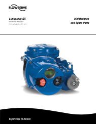
Simulated line rupture test confirms closing speed of <strong>Edward</strong> main steam isolation valve<br />
against differential pressure of 1500 psi.<br />
20<br />
<strong>Edward</strong> <strong>and</strong> <strong>Anchor</strong>/<strong>Darling</strong> valves<br />
constructed for nuclear service can be<br />
offered for Code Class 1, 2 or 3.<br />
<strong>Flowserve</strong> <strong>Edward</strong> <strong>and</strong> <strong>Anchor</strong>/<strong>Darling</strong> <strong>Valves</strong> • 1900 South Saunders Street, Raleigh, North Carolina 27603 • 1-800-225-6989 • 1-919-832-0525 • Fax 1-919-831-3369
<strong>Flowserve</strong> Forged <strong>and</strong> Cast Steel <strong>Valves</strong> for <strong>Nuclear</strong> Service<br />
<strong>Edward</strong> Equiwedge gate valve with an <strong>Edward</strong> gas hydraulic actuator being prepared for shipment.<br />
<strong>Flowserve</strong> <strong>Edward</strong> <strong>and</strong> <strong>Anchor</strong>/<strong>Darling</strong> have<br />
been serving the power generation <strong>and</strong><br />
process industries with custom engineered<br />
valves since 1888.<br />
As a specialist with more than 100 years<br />
of experience in the production of highspecification<br />
valves for critical services, we<br />
are uniquely qualified to serve the needs of<br />
the power generation <strong>and</strong> process industries<br />
worldwide.<br />
From the beginning of commercial nuclear<br />
power production, <strong>Flowserve</strong> valves have<br />
been used successfully in many of the most<br />
difficult applications. The Shippingport plant<br />
went on line in 1957 with special size 18"<br />
<strong>Edward</strong> stainless steel tilting disc check <strong>and</strong><br />
<strong>and</strong> <strong>Anchor</strong>/<strong>Darling</strong> 10" double-disc gate<br />
valves in its primary coolant system. It also<br />
incorporated numerous small <strong>Edward</strong> capped<br />
manual valves. Other “first generation”<br />
commercial nuclear plants are still in<br />
operation with a broad variety of <strong>Edward</strong> <strong>and</strong><br />
<strong>Anchor</strong>/<strong>Darling</strong> forged <strong>and</strong> cast steel valves.<br />
Through the evolution of the pressurized<br />
water reactor (PWR), the boiling water<br />
reactor (BWR) <strong>and</strong> even the liquid metal fast<br />
breeder reactors (LMFBR), <strong>Flowserve</strong> Flow<br />
Control has been involved in meeting the<br />
most difficult challenges. This experience<br />
in engineering, manufacturing <strong>and</strong> quality<br />
assurance provides an excellent basis for<br />
supplying superior valves for nuclear service<br />
— in new construction, retrofit <strong>and</strong> life<br />
extension work.<br />
A major <strong>Flowserve</strong> <strong>Edward</strong> <strong>Valves</strong> nuclear<br />
niche has been the main steam <strong>and</strong> feedwater<br />
isolation market (MSIVs <strong>and</strong> MFIVs). These<br />
safety-related valves must close rapidly,<br />
typically in three to five seconds, to prevent<br />
major leakage in the event of a pipe rupture.<br />
Special <strong>Edward</strong> Flite-Flow valves with air/<br />
spring actuators were used in PWRs until<br />
the <strong>Edward</strong> Equiwedge gate valve <strong>and</strong> stored<br />
energy actuator were developed in the late<br />
1970s. <strong>Edward</strong> Equiwedge MSIVs <strong>and</strong> MFIVs<br />
with stored energy actuators are now in<br />
service on three continents—in PWRs <strong>and</strong> in<br />
steam service in an LMFBR.<br />
Other critical nuclear applications are served<br />
by <strong>Edward</strong> check <strong>and</strong> stop-check valves,<br />
some with special features. <strong>Flowserve</strong><br />
provides comprehensive application<br />
engineering data (see Technical Section) to<br />
support these valves, helping to avoid many<br />
of the problems that have occurred with other<br />
check valves in nuclear power plants.<br />
In addition, thous<strong>and</strong>s of small <strong>Edward</strong><br />
forged steel valves are widely used in many<br />
nuclear plant applications that dem<strong>and</strong><br />
high reliability. Some have h<strong>and</strong>wheels,<br />
some have electric motor actuators <strong>and</strong><br />
some have pneumatic actuators, but all are<br />
designed <strong>and</strong> built to nuclear st<strong>and</strong>ards.<br />
Univalves <strong>and</strong> bolted bonnet valves provide<br />
excellent service in most applications, <strong>and</strong><br />
Hermavalves are available for applications<br />
where the risk of external leakage is<br />
unacceptable.<br />
A major manufacturer of Section III <strong>Nuclear</strong><br />
<strong>Valves</strong>, 1/2" <strong>and</strong> larger <strong>Flowserve</strong> <strong>Edward</strong><br />
<strong>and</strong> <strong>Anchor</strong>/<strong>Darling</strong> offer the most complete<br />
flowserve.com<br />
line of valves developed for nuclear service<br />
where reliable operation, positive sealing,<br />
ease of maintenance <strong>and</strong> A.L.A.R.A. are<br />
prime considerations. Our valves are<br />
produced in the U.S.A. to an ISO 9001<br />
certified quality program.<br />
<strong>Flowserve</strong> <strong>Edward</strong> <strong>and</strong> <strong>Anchor</strong>/<strong>Darling</strong> smallbore<br />
valves are available to ASME Section III<br />
Class 1, 2, 3 or ANSI B16.34 requirements.<br />
<strong>Flowserve</strong> <strong>Edward</strong> <strong>and</strong> <strong>Anchor</strong>/<strong>Darling</strong><br />
valves are available with seating materials<br />
suitable for various applications. Where<br />
required, seat rings are firmly shouldered<br />
against the body <strong>and</strong> vacuum furnace brazed.<br />
This process gives a very precise seating<br />
surface to achieve extended service life.<br />
Seating surfaces are solid alloys that provide<br />
excellent wear <strong>and</strong> corrosion properties<br />
not possible with competitors’ integral seat<br />
designs often seen in forged valves.<br />
Hardface materials offered as a st<strong>and</strong>ard<br />
include non-cobalt NOREM, cobalt-chrome<br />
Stellite <strong>and</strong> various nickel-based alloys.<br />
Since there were 50 years of <strong>Flowserve</strong><br />
power plant valve experience before the<br />
first nuclear plants were built, we were<br />
well prepared for the new challenges of<br />
first-generation nuclear power plants.<br />
Now, with over 50 years of nuclear valve<br />
experience, <strong>Flowserve</strong> <strong>Edward</strong> <strong>and</strong><br />
<strong>Anchor</strong>/<strong>Darling</strong> valves are even better<br />
prepared for the challenges of the future.<br />
<strong>Edward</strong> <strong>and</strong> <strong>Anchor</strong>/<strong>Darling</strong> valves constructed for<br />
nuclear service can be offered for Code class 1, 2<br />
or 3.<br />
21<br />
<strong>Flowserve</strong> <strong>Edward</strong> <strong>and</strong> <strong>Anchor</strong>/<strong>Darling</strong> <strong>Valves</strong> • 1900 South Saunders Street, Raleigh, North Carolina 27603 • 1-800-225-6989 • 1-919-832-0525 • Fax 1-919-831-3369
Checklist of Customer Information<br />
Required for <strong>Nuclear</strong> Valve Proposals<br />
The following checklist is provided as<br />
a guide of important information required<br />
by the valve manufacturer to accurately<br />
quote equipment intended for nuclear<br />
service. By properly identifying this data,<br />
a more complete <strong>and</strong> specific proposal<br />
can be provided.<br />
<strong>Flowserve</strong> <strong>Edward</strong> Stored Energy Actuator<br />
Unlike a safety-related motor operator, designed to open <strong>and</strong> close a<br />
valve upon being enabled by the control room, <strong>Flowserve</strong> <strong>Edward</strong>’s<br />
Gas/Hydraulic – Stored Energy Actuator is primarily designed to<br />
rapidly close a Main Steam Isolation Valve or a Main Feed Water Valve<br />
in response to a seismic event, or other containment threat. Upon<br />
activation of the actuator, in response to such an event, the compressed<br />
nitrogen in the hemisphere at the top of the unit immediately<br />
closes the valve in as little as two (2) seconds. The system includes<br />
a hydraulic reservoir <strong>and</strong> pump either electrically driven or pneumatically<br />
driven. The pump is capable of recompressing the nitrogen into<br />
the storage hemisphere to reposition the valve in the open position;<br />
simultaneously, the actuator is reset to the ready position. This same<br />
mechanism is designed to allow the valve to be exercised (partial<br />
stroked) by operators <strong>and</strong> service technicians.<br />
22<br />
• Certified design specifications.<br />
• <strong>Nuclear</strong> code class.<br />
• Applicable codes/st<strong>and</strong>ards <strong>and</strong> date of issue.<br />
• Estimated delivery requirements.<br />
• Environmental conditions - temperature, humidity, radiation, exposure to elements.<br />
• Piping diagrams.<br />
• Pipe size, material, wall thickness.<br />
• Piping forces transmitted to valve.<br />
• Piping response spectrum to Design Basis Earthquake.<br />
• Dimensional limitations of valve envelope.<br />
• Physical orientation of valve - horizontal, vertical, bonnet position.<br />
• Special materials required.<br />
• Special buttweld end requirements.<br />
• System design conditions - pressure, temperature.<br />
• Normal operating conditions - pressure, temperature.<br />
• Normal flow - pounds per hour.<br />
• Maximum flow - pounds per hour.<br />
• Allowable pressure drop through valve.<br />
• Flow direction through valve.<br />
• Active/non-active valve operational requirements - emergency opening or closing, actuation<br />
time, differential pressures <strong>and</strong> flows during operation.<br />
• Power sources - air supply pressure (maximum <strong>and</strong> minimum) voltage supply (AC, DC),<br />
cycles, fluctuation.<br />
• Actuator type desires.<br />
• Safety related function.<br />
• Qualification requirement.<br />
The <strong>Flowserve</strong> <strong>Edward</strong> Stored Energy Actuator is built in accordance<br />
with ASME Section VIII where required <strong>and</strong> is fully certified to the<br />
applicable IEEE environmental qualification st<strong>and</strong>ards. These<br />
<strong>Flowserve</strong> <strong>Edward</strong> Stored Energy Actuators are in active nuclear<br />
service throughout the world.<br />
Contact <strong>Flowserve</strong> Inc. Flow Control for a listing of U.S. <strong>and</strong> international<br />
users.<br />
<strong>Flowserve</strong> <strong>Edward</strong> <strong>and</strong> <strong>Anchor</strong>/<strong>Darling</strong> <strong>Valves</strong> • 1900 South Saunders Street, Raleigh, North Carolina 27603 • 1-800-225-6989 • 1-919-832-0525 • Fax 1-919-831-3369
Gas-Hydraulic Actuators for Fail-Safe Isolation <strong>Valves</strong><br />
<strong>Flowserve</strong> <strong>Edward</strong> gas-hydraulic actuator for large, fast-closing valves is subjected to seismic<br />
testing during rigorous qualification program to provide dependability of operation under the<br />
most adverse conditions.<br />
St<strong>and</strong>ard Features<br />
• Stored energy (pressurized nitrogen) integrally<br />
contained.<br />
• Hydraulic speed-control system ensures constant valve<br />
stroking speed regardless of stem load.<br />
• Fail-safe operation to either close or open valve within<br />
an adjustable range of 2 to 10 seconds.<br />
• Self-contained control system, fully manifolded.<br />
• All safety-related functional components are duplicated<br />
for redundancy.<br />
• Exercise capability demonstrates operation of all safetyrelated<br />
components online.<br />
• Qualified to applicable IEEE requirements.<br />
• Actuators equipped with <strong>Edward</strong> IEEE-qualified AC or<br />
DC operated hydraulic solenoid valves.<br />
• Fire safe, non-toxic hydraulic fluid.<br />
<strong>Flowserve</strong> - <strong>Edward</strong> Actuator Designation<br />
flowserve.com<br />
Diagram of <strong>Flowserve</strong> <strong>Edward</strong><br />
Equiwedge gate valve <strong>and</strong><br />
gas-hydraulic actuator assembly.<br />
Black numerals are in inches <strong>and</strong> pounds<br />
Colored numerals are in millimeters <strong>and</strong> kilograms<br />
Units A/B-100 A/B-180 A/B-230 A/B-260 A/B-290 A/B-330 A/B-510<br />
Closing Thrust<br />
lb.<br />
kN<br />
21,000<br />
93<br />
63,000<br />
293<br />
90,000<br />
400<br />
130,000<br />
578<br />
160,000<br />
712<br />
205,000<br />
912<br />
489,000<br />
2175<br />
Travel<br />
in.<br />
mm<br />
6.5<br />
165<br />
12<br />
305<br />
14<br />
356<br />
17.5<br />
446<br />
20.5<br />
521<br />
24<br />
610<br />
32<br />
813<br />
Weight (Mass)<br />
lb.<br />
kg<br />
720<br />
325<br />
1720<br />
780<br />
2270<br />
1030<br />
2950<br />
1340<br />
3940<br />
1790<br />
5260<br />
2390<br />
17,700<br />
8030<br />
Extension Time sec. 3 − 10 SECONDS (ADJUSTABLE)<br />
Values tabulated are “nominal.” For special applications; otherwise, st<strong>and</strong>ard actuators may be modified for shorter or longer travel with<br />
corresponding effects on weight. Environmental temperature range of the application will influence thrust.<br />
<strong>Flowserve</strong> <strong>Edward</strong> <strong>and</strong> <strong>Anchor</strong>/<strong>Darling</strong> <strong>Valves</strong> • 1900 South Saunders Street, Raleigh, North Carolina 27603 • 1-800-225-6989 • 1-919-832-0525 • Fax 1-919-831-3369<br />
23
Main Steam <strong>and</strong> Main Feedwater Isolation <strong>Valves</strong><br />
Gas / Hydraulic Actuated Equiwedge Gate <strong>Valves</strong><br />
• Single stored energy system / redundant control systems.<br />
• St<strong>and</strong>ard features include:<br />
• Manifold-mounted hydraulic components<br />
• Off-line testing capabilities<br />
• Exercise stroke capabilities<br />
• Extended periods between maintenance<br />
• No external hose or piping connections<br />
Since 1985, over 80% of the world’s MSIVs <strong>and</strong> MFIVs have been<br />
supplied by <strong>Flowserve</strong>!<br />
• Simple design <strong>and</strong> operating principle<br />
• Extensive, proven track record<br />
• Environmentally <strong>and</strong> functionally qualified valve <strong>and</strong> actuator<br />
• <strong>Flowserve</strong> service, training <strong>and</strong> warranty<br />
• No failures to perform safety-related function<br />
• Over 9,000 service years of reliable operation<br />
24<br />
• Similar in weight <strong>and</strong> smaller than pneumatic actuators.<br />
• Consistent stroke times.<br />
• Fluid filtration systems prevent particulate contamination of<br />
hydraulic fluid.<br />
• Environmental qualification to IEEE-382, 323 <strong>and</strong> 344.<br />
• ASME B16.41 <strong>and</strong> QME-1 functionally qualified.<br />
<strong>Flowserve</strong> <strong>Edward</strong> <strong>and</strong> <strong>Anchor</strong>/<strong>Darling</strong> <strong>Valves</strong> • 1900 South Saunders Street, Raleigh, North Carolina 27603 • 1-800-225-6989 • 1-919-832-0525 • Fax 1-919-831-3369
flowserve.com<br />
<strong>Edward</strong> Gate <strong>Valves</strong><br />
<strong>Flowserve</strong> <strong>Edward</strong> <strong>and</strong> <strong>Anchor</strong>/<strong>Darling</strong> <strong>Valves</strong> • 1900 South Saunders Street, Raleigh, North Carolina 27603 • 1-800-225-6989 • 1-919-832-0525 • Fax 1-919-831-3369<br />
25
Features <strong>and</strong> Description of <strong>Flowserve</strong> <strong>Edward</strong> Equiwedge ®<br />
For detailed description of the two-piece flexible wedge, see page 28.<br />
1. Yoke bushing – material has low coefficient of friction<br />
that substantially reduces torque <strong>and</strong> thread wear <strong>and</strong><br />
eliminates galling.<br />
2. Weather/Grease seals – are provided to protect against<br />
environmental conditions.<br />
3. Yoke – the yoke is designed for ready access to the packing<br />
chamber.<br />
4. Packing <strong>and</strong> junk ring – utilizes flexible graphite packing material<br />
with anti-extrusion rings for optimum sealability <strong>and</strong> life.<br />
5. Extended bonnet design – further separates the packing chamber<br />
from fluid flow area for longer packing life. Also provides<br />
accessible area for leakoff connections if required.<br />
6. Composite pressure seal gasket – preloaded, pressure energized<br />
design, for long, reliable service.<br />
7. Body guiding system – holds the wedge halves together <strong>and</strong><br />
absorbs thrust loads due to line flow. Integral hardfaced guide<br />
system components reduce friction <strong>and</strong> prevent galling for longer<br />
valve life.<br />
8. Conical stem backseat – Cone-on-cone design provides a reliable<br />
sealing geometry that operates over many valve cycles without<br />
leakage.<br />
9. Body – rugged cast steel body provides maximum flow efficiency.<br />
Information on alternate materials can be obtained through your<br />
<strong>Flowserve</strong> representative.<br />
10. H<strong>and</strong>wheel – spoke design provides more efficient transfer of<br />
load with minimum weight.<br />
26<br />
1.<br />
2<br />
3.<br />
4.<br />
5.<br />
6.<br />
7.<br />
8.<br />
9.<br />
Gate <strong>Valves</strong><br />
11. Tapered roller bearings – on larger valves, tapered roller<br />
bearings reduce torque, carry the stem thrust <strong>and</strong> provide<br />
additional radial support for side loads imposed by h<strong>and</strong>wheel or<br />
power actuator. Smaller size valves have needle roller bearings.<br />
12. Stem – has ACME threads, is machined to a fine finish <strong>and</strong> is heat<br />
treated for improved strength <strong>and</strong> hardness to resist wear.<br />
13. Packing gl<strong>and</strong> – made of alloy steel, <strong>and</strong> retained against the<br />
stuffing box pressure by an easy-to-maintain stud <strong>and</strong> heavy hex<br />
nut assembly.<br />
14. Bonnet retaining ring – ensures an effective, tight seal by pulling<br />
the bonnet <strong>and</strong> gasket together at the pressure seal.<br />
15. Yoke lock ring – permits easier field maintenance of upper<br />
structure without disturbing pressure-containing parts. <strong>Valves</strong><br />
in smaller sizes utilize a wishbone yoke design. Class 600 valves<br />
utilize a bolted pressure seal bonnet.<br />
16. Bonnet backseat – especially hardfaced to ensure<br />
long-term sealability.<br />
17. Hemispherical-type bonnet – reduces valve body height <strong>and</strong><br />
provides weight saving. Hemispherical-type design results in<br />
better pressure distribution across the bonnet area.<br />
18. Two-piece wedge assembly – allows each wedge half to flex <strong>and</strong><br />
adjust independently to compensate for body distortions caused<br />
by thermal changes or pipe bending stresses. (see pg. C10)<br />
19. Welded-in seat ring with hardfaced seat – ensures better wear<br />
<strong>and</strong> longer valve life. Seat ring is welded into the valve body to<br />
prevent leakage.<br />
<strong>Flowserve</strong> <strong>Edward</strong> <strong>and</strong> <strong>Anchor</strong>/<strong>Darling</strong> <strong>Valves</strong> • 1900 South Saunders Street, Raleigh, North Carolina 27603 • 1-800-225-6989 • 1-919-832-0525 • Fax 1-919-831-3369<br />
10.<br />
11.<br />
12.<br />
13.<br />
14.<br />
15.<br />
16.<br />
17.<br />
18.<br />
19.
Parts Specification List for <strong>Edward</strong> Gate <strong>Valves</strong><br />
flowserve.com<br />
This is not a complete list. Construction <strong>and</strong> materials will vary between sizes <strong>and</strong> pressure classes <strong>and</strong> may be changed without notice.<br />
For a complete, accurate <strong>and</strong> itemized description of a particular valve, contact your <strong>Flowserve</strong> valves sales representative.<br />
Description ASME No. ASME No. ASME No. ASME No.<br />
Body/Bonnet*<br />
SA-216<br />
Grade WCB<br />
SA-216<br />
Grade WCC<br />
SA-217<br />
Grade WC9<br />
SA-351<br />
Grade CF8M<br />
Gate 21/2-6<br />
SA-732<br />
Grade 21<br />
SA-732<br />
Grade 21<br />
SA-732<br />
Grade 21<br />
SA-732<br />
Grade 21<br />
Gate 8 <strong>and</strong> up*<br />
SA-216<br />
Grade WCB<br />
SA-216<br />
Grade WCB<br />
SA-217<br />
Grade WC9<br />
SA-351<br />
Grade CF8M<br />
Stem<br />
A-182<br />
Grade F6 CL4<br />
A-182<br />
Grade F6 CL4<br />
A-565<br />
Grade 616 HT<br />
A-638<br />
Grade 660 T2<br />
Yoke Bushing<br />
B-148<br />
Alloy 95400<br />
B-148<br />
Alloy 95400<br />
B-148<br />
Alloy 95400<br />
B-148<br />
Alloy 95400<br />
Packing Rings Flexible Graphite inner rings <strong>and</strong> suitable anti-extrusion rings.<br />
Junk Rings<br />
AISI 1117<br />
MnPo 4 Plated<br />
AISI 1117<br />
MnPo 4 Plated<br />
AISI 1117<br />
MnPo 4 Plated<br />
Pressure Seal Gasket Composite Pressure Seal Gasket.<br />
Spacer Ring<br />
Gasket Retainer<br />
Bonnet Retainer<br />
Bonnet Retainer Studs<br />
Bonnet Retainer Nuts<br />
Gl<strong>and</strong><br />
Gl<strong>and</strong> Studs<br />
Gl<strong>and</strong> Nuts<br />
Yoke<br />
Yoke Lock Ring<br />
Yoke Lock Ring Studs<br />
Yoke Lock Ring Nuts<br />
H<strong>and</strong>wheel<br />
—<br />
A-668 Grade 4140<br />
MnPO 4 Plated<br />
A-182<br />
Grade F6 CL4<br />
A-515<br />
Grade 70<br />
A-193<br />
Grade B7<br />
A-194<br />
Grade 2H<br />
A-148<br />
Grade 90-60<br />
A-193<br />
Grade B7<br />
A-194<br />
Grade 2H<br />
A-216<br />
Grade WCB<br />
A-216<br />
Grade WCB<br />
A-193<br />
Grade B7<br />
A-194<br />
Grade 2H<br />
A-126<br />
Class A<br />
*Hardfaced wedge guide rails <strong>and</strong> seating surfaces.<br />
**Use A-368 Grade 660 T2 for applications over 1100°F<br />
—<br />
A-668 Grade 4140<br />
MnPO 4 Plated<br />
A-182<br />
Grade F6 CL4<br />
A-515<br />
Grade 70<br />
A-193<br />
Grade B7<br />
A-194<br />
Grade 2H<br />
A-148<br />
Grade 90-60<br />
A-193<br />
Grade B7<br />
A-194<br />
Grade 2H<br />
A-216<br />
Grade WCB<br />
A-216<br />
Grade WCB<br />
A-193<br />
Grade B7<br />
A-194<br />
Grade 2H<br />
A-126<br />
Class A<br />
—<br />
A-668 Grade 4140<br />
MnPO 4 Plated<br />
A-565<br />
Grade 616 HT<br />
A-515<br />
Grade 70<br />
A-193<br />
Grade B7<br />
A-194<br />
Grade 2H<br />
A-148<br />
Grade 90-60<br />
A-193<br />
Grade B7<br />
A-194<br />
Grade 2H<br />
A-216<br />
Grade WCB<br />
A-216<br />
Grade WCB<br />
A-193<br />
Grade B7<br />
A-194<br />
Grade 2H<br />
A-126<br />
Class A<br />
A-182<br />
Grade F316/Stellite I.D.<br />
—<br />
A-182<br />
Grade F6 CL4<br />
A-638<br />
Grade 660 T2<br />
A-515<br />
Grade 70<br />
A-193<br />
Grade B7<br />
A-194<br />
Grade 2H<br />
A-148<br />
Grade 90-60/Chrome Plated<br />
A-193<br />
Grade B7<br />
A-194<br />
Grade 2H<br />
A-216<br />
Grade WCB<br />
A-216<br />
Grade WCB<br />
A-193<br />
Grade B7<br />
A-194<br />
Grade 2H<br />
A-126<br />
Class A<br />
<strong>Flowserve</strong> <strong>Edward</strong> <strong>and</strong> <strong>Anchor</strong>/<strong>Darling</strong> <strong>Valves</strong> • 1900 South Saunders Street, Raleigh, North Carolina 27603 • 1-800-225-6989 • 1-919-832-0525 • Fax 1-919-831-3369<br />
27
Features <strong>and</strong> Description of <strong>Flowserve</strong> <strong>Edward</strong> Equiwedge ®<br />
Unique Two-Piece Flexible Wedge<br />
Wedging action provides tight seat sealing,<br />
even at low differential pressures. Wedge<br />
guiding by grooves in body minimizes seat<br />
wear <strong>and</strong> damage, since seating surfaces<br />
of wedge <strong>and</strong> body are in contact over less<br />
than 5% of total travel. Two separate, flexible<br />
wedge halves are free to align with seats even<br />
when they are tilted or rotated due to thermal<br />
effects or piping loads. Resistance to thermal<br />
binding ensures opening with a torque<br />
or load less than design closing load.<br />
Wedge guide area <strong>and</strong> strength provide<br />
capability to support high differential<br />
pressures with valve partially open,<br />
so Equiwedge gate valves can be opened<br />
or closed under “blowdown” conditions.<br />
Bypasses are not required if full differential is<br />
specified for actuator sizing.<br />
Center Cavity<br />
Overpressurization<br />
Some valve designs are capable of sealing<br />
simultaneously against a pressure differential<br />
between an internal cavity of the valve <strong>and</strong><br />
the adjacent pipe in both directions. Doubleseated<br />
gate valves, including Equiwedge,<br />
are examples of such a design. In fact, seat<br />
joint integrity for these valves is tested in<br />
the factory by pressurizing the center cavity<br />
<strong>and</strong> simultaneously examining each seat.<br />
However, if a fluid is entrapped in such a<br />
valve while closed, <strong>and</strong> then subsequently<br />
heated, a dangerous rise in pressure can<br />
result, thus leading to pressure boundary<br />
failure.<br />
Both ASME B16.34 (<strong>Valves</strong> - Flanged,<br />
Threaded <strong>and</strong> Welding End), para 2.3.3 <strong>and</strong><br />
ASME B31.1 (Pressure Piping Code), para<br />
107.1(c), recognize this situation <strong>and</strong> require<br />
that the Purchaser shall provide means<br />
in design, installation <strong>and</strong>/or operation to<br />
ensure that the pressure in the valve shall<br />
not exceed the rated pressure for the attained<br />
temperature. Therefore, if deemed necessary<br />
by the Purchaser, <strong>and</strong> so specified in the<br />
purchase order, <strong>Flowserve</strong> <strong>Edward</strong> <strong>Valves</strong><br />
can provide an equalizer system (internal or<br />
external) that will relieve this trapped fluid to<br />
the upstream piping or a relief valve that will<br />
exhaust excessive pressure to some other<br />
specified area. It should be understood that<br />
an internal or external equalizer will change<br />
a basically bidirectional gate valve to a<br />
28<br />
Two-Piece Wedge<br />
Hardfaced Wedge<br />
Guide Rails<br />
Body<br />
Groove<br />
Body<br />
Figure 1<br />
Wedge Halves<br />
The outst<strong>and</strong>ing design feature<br />
of the Equiwedge gate valve is<br />
unique two-piece wedge that<br />
permits maximum independence<br />
<strong>and</strong> flexibility for good sealability<br />
<strong>and</strong> freedom from sticking.<br />
Back Face of Wedge Half<br />
Wedge Half<br />
Figure 3<br />
Hardfaced<br />
Wedge Seat<br />
Non-revolving<br />
Stem<br />
Wedge halves are separated<br />
the proper amount by a spacer<br />
ring which provides controlled<br />
deflection from stem loading.<br />
Use of a space <strong>and</strong> weight-saving<br />
“captured stem” (shown here <strong>and</strong><br />
in Figure 4) is possible because<br />
of the two-piece wedge design.<br />
Guiding System<br />
Hardfaced Wedge<br />
Guide Rails<br />
Figure 2<br />
The body groove extends high in<br />
the body neck region so that in<br />
the open position the wedge assembly<br />
is both trapped <strong>and</strong> fully<br />
guided. Body grooves are hardfaced<br />
for critical service valves.<br />
Gate <strong>Valves</strong><br />
Body Grooves<br />
<strong>Flowserve</strong> <strong>Edward</strong> <strong>and</strong> <strong>Anchor</strong>/<strong>Darling</strong> <strong>Valves</strong> • 1900 South Saunders Street, Raleigh, North Carolina 27603 • 1-800-225-6989 • 1-919-832-0525 • Fax 1-919-831-3369<br />
Spacer Ring<br />
design with fully effective seat sealing in only<br />
one direction. The equalizer bypasses the<br />
upstream seat <strong>and</strong> would allow leakage by<br />
that seat if the pressure should be reversed.<br />
The “downstream” seat would become the<br />
“upstream” seat with pressure reversed;<br />
the wedging action provided by stem load<br />
provides good upstream seat sealing at low<br />
to moderate pressures, but leakage could be<br />
excessive at high pressures.<br />
Excessive pressure trapped in the center<br />
cavity of a gate valve can also produce<br />
“Captured Stem”<br />
Stem Seating<br />
Shoulder<br />
Figure 4<br />
Welded-in<br />
Seat Ring<br />
Body<br />
Stem<br />
Backseat<br />
Wedge Half Wedge Half<br />
The Equiwedge two-piece wedge<br />
design allows the use of a space<br />
<strong>and</strong> weight-saving “captured<br />
stem.”<br />
“pressure locking”—a condition that can<br />
make opening difficult or impossible.<br />
Either an internal or an external equalizer<br />
will prevent pressure locking. However,<br />
a relief valve may allow the center cavity<br />
pressure to be higher than either the<br />
upstream or downstream pressure, <strong>and</strong> this<br />
can allow pressure locking to occur. The<br />
<strong>Flowserve</strong> <strong>Edward</strong> valves’ unique ACCEV<br />
(Automation Center Cavity Equalizing Valve)<br />
can alleviate this problem. Refer to page 197<br />
for additional information.
Equiwedge Stop <strong>Valves</strong>, Class 600<br />
St<strong>and</strong>ard Features<br />
• Bodies <strong>and</strong> bonnets are cast steel<br />
(WCB, WCC, WC9, CF8M)<br />
• Pressure-seal bonnet OS & Y<br />
• Integral Stellite seats <strong>and</strong> backseat<br />
• Two-piece body-guided wedge<br />
• 13% chromium stainless steel stem<br />
• Asbestos-free graphitic packing<br />
• Composite pressure-seal gasket<br />
• Available in st<strong>and</strong>ard or venturi pattern<br />
• Yoke bushing thrust bearings<br />
Dimensions – Equiwedge Gate<br />
Figure No. 1611/1611Y, 1711Y<br />
A - End to End (Welding)<br />
C - Face to Face (Flanged)<br />
E - Center to Top, (Open)<br />
G - H<strong>and</strong>wheel Diameter<br />
Weight (Welding)<br />
Pressure Class 600 (PN 110)<br />
Fig. No.<br />
STD CL SPL CL<br />
Type Ends Bonnet NPS (DN)<br />
1611* — Equiwedge Gate Flanged Pressure Seal<br />
1611Y 1711Y Equiwedge Gate Butt Weld Pressure Seal<br />
1611BY 1711BY<br />
* E, G, <strong>and</strong> other dimensions <strong>and</strong> information supplied upon request.<br />
Refer to page 27 for materials of construction.<br />
Refer to pages 203 through 238 for the applicable pressure ratings.<br />
* Flanges to size 24 only.<br />
Venturi Pattern<br />
Equiwedge Gate<br />
flowserve.com<br />
21/2 (65) thru 28 (700)<br />
Butt Weld Pressure Seal 8 (200) thru 32 (800)<br />
Black numerals are in inches <strong>and</strong> pounds<br />
Colored numerals are in millimeters <strong>and</strong> kilograms<br />
NPS 21/2 3 4 6 8 10 12 14<br />
DN 65 80 100 150 200 250 300 350<br />
10 10 12 18 23 28 32 35<br />
254 254 305 457 584 711 813 889<br />
13 14 17 22 26 31 33 35<br />
330 356 432 559 660 787 838 889<br />
22.25 22.25 25.5 31.75 39.75 48 54 58.5<br />
565 565 648 806 1010 1219 1372 1486<br />
14 14 14 24 24 30 30 36<br />
356 356 356 610 610 762 762 914<br />
81 81 175 372 667 1050 1623 2345<br />
37 37 79 169 303 476 738 1066<br />
<strong>Flowserve</strong> <strong>Edward</strong> <strong>and</strong> <strong>Anchor</strong>/<strong>Darling</strong> <strong>Valves</strong> • 1900 South Saunders Street, Raleigh, North Carolina 27603 • 1-800-225-6989 • 1-919-832-0525 • Fax 1-919-831-3369<br />
1611Y<br />
29
Equiwedge Stop <strong>Valves</strong>, Class 600<br />
Dimensions – Equiwedge Gate (continued)<br />
Black numerals are in inches <strong>and</strong> pounds<br />
Colored numerals are in millimeters <strong>and</strong> kilograms<br />
Figure No. 1611/1611Y, 1711Y<br />
NPS<br />
DN<br />
16<br />
400<br />
18<br />
450<br />
20<br />
500<br />
22<br />
550<br />
24<br />
600<br />
26<br />
650<br />
28<br />
700<br />
A - End to End (Welding)<br />
39<br />
991<br />
43<br />
1092<br />
47<br />
1194<br />
51<br />
1295<br />
55<br />
1397<br />
57<br />
1448<br />
61<br />
1549<br />
C - Face to Face (Flanged)<br />
39<br />
991<br />
43<br />
1092<br />
47<br />
1194<br />
51<br />
1295<br />
55<br />
1397<br />
57<br />
1448<br />
61<br />
1549<br />
E - Center to Top, (Open)<br />
67<br />
1702<br />
76<br />
1930<br />
82.75<br />
2102<br />
89<br />
2261<br />
96<br />
2438<br />
101<br />
2565<br />
110.5<br />
2807<br />
G - H<strong>and</strong>wheel Diameter<br />
36<br />
914<br />
36<br />
914<br />
36<br />
914<br />
48<br />
1219<br />
48<br />
1219<br />
48<br />
1219<br />
48<br />
1219<br />
Weight (Welding)<br />
2950<br />
1338<br />
3600<br />
1633<br />
5000<br />
2268<br />
5700<br />
2585<br />
6500<br />
2948<br />
8000<br />
3628<br />
10,000<br />
4535<br />
* E, G <strong>and</strong> other dimensions <strong>and</strong> information supplied upon request.<br />
Dimensions – Equiwedge Gate<br />
Venturi Pattern<br />
Figure No. 1611BY, 1711BY<br />
A - End to End (Welding)<br />
E - Center to Top, (Open)<br />
G - H<strong>and</strong>wheel Diameter<br />
Weight (Welding)<br />
Figure No. 1611BY, 1711BY<br />
A - End to End (Welding)<br />
E - Center to Top, (Open)<br />
G - H<strong>and</strong>wheel Diameter<br />
Weight (Welding)<br />
Refer to page 27 for materials of construction.<br />
Refer to pages 203 through 238 for the applicable pressure ratings.<br />
30<br />
Black numerals are in inches <strong>and</strong> pounds<br />
Colored numerals are in millimeters <strong>and</strong> kilograms<br />
NPS 8x6x8 10x8x10 12x10x12 14x12x14 16x14x16 18x16x18<br />
DN 200 250 300 350 400 450<br />
18 23 28 32 35 39<br />
457 584 711 813 889 991<br />
31.75 39.75 48 54 58.5 67<br />
806 1010 1219 1372 1486 1702<br />
24 24 30 30 36 36<br />
610 610 762 762 914 914<br />
372 610 1114 1623 2345 2950<br />
169 277 506 738 1066 1338<br />
NPS 20x18x20 22x20x22 24x20x24 26x22x26 28x24x28 30x26x30 32x28x32<br />
DN 500 550 600 650 700 750 800<br />
43 47 47 51 55 57 61<br />
1092 1194 1194 1295 1397 1448 1549<br />
76 82.75 82.75 89 96 101 110.5<br />
1930 2102 2102 2261 2438 2565 2807<br />
36 36 48 48 48 48 48<br />
914 914 1219 1219 1219 1219 1219<br />
3600 5000 5700 6500 7000 8500 10,500<br />
1633 2268 2585 2948 3175 3855 4762<br />
<strong>Flowserve</strong> <strong>Edward</strong> <strong>and</strong> <strong>Anchor</strong>/<strong>Darling</strong> <strong>Valves</strong> • 1900 South Saunders Street, Raleigh, North Carolina 27603 • 1-800-225-6989 • 1-919-832-0525 • Fax 1-919-831-3369
Equiwedge Stop <strong>Valves</strong>, Class 900<br />
St<strong>and</strong>ard Features<br />
• Bodies <strong>and</strong> bonnets are cast steel<br />
(WCB, WCC, WC9, CF8M)<br />
• Pressure-seal bonnet, OS <strong>and</strong> Y<br />
• Integral Stellite seat, disc <strong>and</strong> backseat<br />
• Two-piece body-guided wedge<br />
• 13% chromium stainless steel stem<br />
• Asbestos-free graphitic packing<br />
• Available in st<strong>and</strong>ard or venturi pattern<br />
• Yoke bushing thrust bearings<br />
• Composite pressure seal gasket<br />
Dimensions – Equiwedge Gate<br />
Figure No. 1911/1911Y, 14311Y<br />
A - End to End (Welding)<br />
C - Face to Face (Flanged)<br />
E - Center to Top (Open)<br />
G - H<strong>and</strong>wheel Diameter<br />
Weight (Welding)<br />
Pressure Class 900 (PN 150)<br />
Fig. No.<br />
STD CL SPL CL<br />
Type Ends Bonnet NPS (DN)<br />
1911 — Equiwedge Gate Flanged Pressure-Seal<br />
1911Y 14311Y Equiwedge Gate Butt Weld Pressure-Seal<br />
1911BY 14311BY<br />
Refer to page 27 for materials of construction.<br />
Refer to pages 203 through 238 for the applicable pressure ratings.<br />
Venturi Pattern<br />
Equiwedge Gate<br />
flowserve.com<br />
21/2 (65) thru 28 (700)<br />
Butt Weld Pressure-Seal 8 (200) thru 32 (800)<br />
Black numerals are in inches <strong>and</strong> pounds<br />
Colored numerals are in millimeters <strong>and</strong> kilograms<br />
NPS 21/2 3 4 6 8 10 12 14<br />
DN 65 80 100 150 200 250 300 350<br />
12 12 14 20 26 31 36 39<br />
305 305 356 508 660 787 914 991<br />
16.5 15 18 24 29 33 38 40.5<br />
419 381 457 610 737 838 965 1029<br />
21.25 21.25 24.5 33.5 40 46.75 54.5 59<br />
540 540 622 851 1016 1187 1384 1499<br />
14 14 18 24 24 36 36 36<br />
356 356 457 610 610 914 914 914<br />
95 125 165 380 690 1523 2118 2805<br />
43 57 75 172 313 692 963 1275<br />
<strong>Flowserve</strong> <strong>Edward</strong> <strong>and</strong> <strong>Anchor</strong>/<strong>Darling</strong> <strong>Valves</strong> • 1900 South Saunders Street, Raleigh, North Carolina 27603 • 1-800-225-6989 • 1-919-832-0525 • Fax 1-919-831-3369<br />
31
Equiwedge Stop <strong>Valves</strong>, Class 900<br />
Dimensions – Equiwedge Gate (continued)<br />
Figure No. 1911/1911Y, 14311Y<br />
A - End to End (Welding)<br />
C - Face to Face (Flanged)<br />
E - Center to Top (Open)<br />
G - H<strong>and</strong>wheel Diameter<br />
Weight (Welding)<br />
Dimensions – Equiwedge Gate<br />
Venturi Pattern<br />
Figure No. 1911BY, 14311BY<br />
A - End to End (Welding)<br />
E - Center to Top (Open)<br />
G - H<strong>and</strong>wheel Diameter<br />
Weight (Welding)<br />
Figure No. 1911BY, 14311BY<br />
A - End to End (Welding)<br />
E - Center to Top (Open)<br />
G - H<strong>and</strong>wheel Diameter<br />
Weight (Welding)<br />
Refer to page 27 for materials of construction.<br />
Refer to pages 203 through 238 for the applicable pressure ratings.<br />
32<br />
Black numerals are in inches <strong>and</strong> pounds<br />
Colored numerals are in millimeters <strong>and</strong> kilograms<br />
NPS 16 18 20 22 24 26 28<br />
DN 400 450 500 550 600 650 700<br />
43 48 52 57 61 64 68<br />
1092 1291 1321 1448 1549 1626 1727<br />
44.5<br />
1130<br />
48<br />
1291<br />
52<br />
1321<br />
57<br />
1448<br />
61<br />
1549<br />
Available Upon Request<br />
68 73.75 82 89.25 95 102 109<br />
1727 1873 2083 2267 2413 2591 2769<br />
36 36 48 48 48 60 60<br />
914 914 1219 1219 1219 1524 1524<br />
4150 4300 5800 7500 9600 12,000<br />
1882 1950 2631 3402 4355 5443<br />
Black numerals are in inches <strong>and</strong> pounds<br />
Colored numerals are in millimeters <strong>and</strong> kilograms<br />
NPS 8x6x8 10x8x10 12x10x12 14x12x14 16x14x16 18x16x18<br />
DN 200 250 300 350 400 450<br />
20 26 31 36 39 43<br />
508 660 787 914 991 1092<br />
33.5 40 46.75 54.5 59 68<br />
851 1016 1187 1384 1499 1727<br />
24 24 36 36 36 36<br />
610 610 914 914 914 914<br />
530 891 1523 2118 2805 4150<br />
241 405 692 963 1275 1882<br />
NPS 20x18x20 22x20x22 24x20x24 26x22x26 28x24x28 30x26x30 32x28x32<br />
DN 500 550 600 650 700 750 800<br />
48 52 52 57 61 64 68<br />
1219 1321 1321 1448 1549 1626 1727<br />
73.75 82 82 89.25 95 102 109<br />
1873 2083 2083 2267 2413 2591 2769<br />
36 48 48 48 48 60 60<br />
914 1219 1219 1219 1219 1524 1524<br />
4500 6970 7200 8000 10,000 12,500 15,000<br />
2041 3162 3266 3629 4536 5670 6804<br />
<strong>Flowserve</strong> <strong>Edward</strong> <strong>and</strong> <strong>Anchor</strong>/<strong>Darling</strong> <strong>Valves</strong> • 1900 South Saunders Street, Raleigh, North Carolina 27603 • 1-800-225-6989 • 1-919-832-0525 • Fax 1-919-831-3369
Equiwedge Stop <strong>Valves</strong>, Class 1500<br />
St<strong>and</strong>ard Features<br />
• Bodies <strong>and</strong> bonnets are cast steel<br />
(WCB, WCC, WC9, CF8M)<br />
• Pressure-seal bonnet, OS & Y<br />
• Integral Stellite seats <strong>and</strong> backseat<br />
• Two-piece body-guided wedge<br />
• 13% chromium stainless steel stem<br />
• Asbestos-free graphitic packing<br />
• Available in st<strong>and</strong>ard or venturi pattern<br />
• Yoke bushing thrust bearings<br />
Dimensions – Equiwedge Gate<br />
Figure No. 11511/11511Y, 12011Y<br />
A - End to End (Welding)<br />
C - Face to Face (Flanged)<br />
E - Center to Top (Open)<br />
G - H<strong>and</strong>wheel Diameter<br />
Weight (Welding)<br />
Figure No. 11511/11511Y, 12011Y<br />
A - End to End (Welding)<br />
C - Face to Face (Flanged)<br />
E - Center to Top (Open)<br />
G - H<strong>and</strong>wheel Diameter<br />
Weight (Welding)<br />
Refer to page 27 for materials of construction.<br />
Refer to pages 203 through 238 for the applicable pressure ratings.<br />
Pressure Class 1500 (PN 260)<br />
Fig. No.<br />
STD CL SPL CL<br />
Type Ends NPS (DN)<br />
11511 — Equiwedge Gate Flanged*<br />
11511Y 12011Y Equiwedge Gate Butt Weld<br />
11511BY 12011BY<br />
Venturi Pattern<br />
Equiwedge Gate<br />
* Optional weld-on flanges.<br />
flowserve.com<br />
21/2 (65) thru 24 (600)<br />
Butt Weld 8 (200) thru 28 (700)<br />
Black numerals are in inches <strong>and</strong> pounds<br />
Colored numerals are in millimeters <strong>and</strong> kilograms<br />
NPS 21/2 3 4 6 8 10 12<br />
DN 65 80 100 150 200 250 300<br />
12 12 16 22 28 34 39<br />
305 305 406 559 711 864 991<br />
16.5 18.5 21.5 27.75 32.75 39 44.5<br />
419 470 546 705 832 991 1130<br />
21.25 21.25 24.25 31.5 40 48.25 55.25<br />
540 540 616 800 1016 1226 1403<br />
14 14 18 24 36 36 36<br />
356 356 457 610 914 914 914<br />
125 125 190 490 675 1730 2725<br />
57 57 86 222 306 785 1236<br />
NPS 14 16 18 20 22 24<br />
DN 350 400 450 500 550 600<br />
42 47 53 58 67 76.5<br />
1067 1194 1346 1473 1702 1943<br />
49.5 54.5 60.5 65.5 71 76.5<br />
1257 1384 1537 1664 1803 1943<br />
61 68.75 73.75 80 86.75 93.5<br />
1549 1746 1873 2032 2203 2375<br />
48 48 48 60 60 60<br />
1219 1219 1219 1524 1524 1524<br />
3660 4450 6000 8000 10,500 13,000<br />
1660 2019 2722 3629 4763 5897<br />
<strong>Flowserve</strong> <strong>Edward</strong> <strong>and</strong> <strong>Anchor</strong>/<strong>Darling</strong> <strong>Valves</strong> • 1900 South Saunders Street, Raleigh, North Carolina 27603 • 1-800-225-6989 • 1-919-832-0525 • Fax 1-919-831-3369<br />
33
Equiwedge Stop <strong>Valves</strong>, Class 1500<br />
Dimensions – Equiwedge Gate Venturi Pattern<br />
Figure No. 11511BY, 12011BY<br />
A - End to End (Welding)<br />
E - Center to Top (Open)<br />
G - H<strong>and</strong>wheel Diameter<br />
Weight (Welding)<br />
Figure No. 11511BY, 12011BY<br />
A - End to End (Welding)<br />
E - Center to Top (Open)<br />
G - H<strong>and</strong>wheel Diameter<br />
Weight (Welding)<br />
Refer to page 27 for materials of construction.<br />
Refer to pages 203 through 238 for the applicable pressure ratings.<br />
34<br />
Black numerals are in inches <strong>and</strong> pounds<br />
Colored numerals are in millimeters <strong>and</strong> kilograms<br />
NPS 8x6x8 10x8x10 12x10x12 14x12x14 16x14x16 18x16x18<br />
DN 200 250 300 350 400 450<br />
22 28 34 39 42 47<br />
559 711 864 991 1067 1194<br />
31.5 40 48.25 55.25 61 68.75<br />
800 1016 1226 1403 1549 1746<br />
24 36 36 36 48 48<br />
610 914 914 914 1219 1219<br />
490 1082 1690 2725 3600 4600<br />
222 491 767 1236 1633 2087<br />
NPS 20x18x20 22x20x22 24x20x24 26x22x26 28x24x28<br />
DN 500 550 600 650 700<br />
53 58 58 67 76.5<br />
1346 1473 1473 1702 1943<br />
73.75 80 80 86.75 93.5<br />
1873 2032 2032 2203 2375<br />
48 60 60 60 60<br />
1219 1524 1524 1524 1524<br />
6200 8200 8,500 11,000 13,500<br />
2812 3720 3855 4990 6124<br />
<strong>Flowserve</strong> <strong>Edward</strong> <strong>and</strong> <strong>Anchor</strong>/<strong>Darling</strong> <strong>Valves</strong> • 1900 South Saunders Street, Raleigh, North Carolina 27603 • 1-800-225-6989 • 1-919-832-0525 • Fax 1-919-831-3369
flowserve.com<br />
<strong>Anchor</strong>/<strong>Darling</strong> Gate <strong>Valves</strong><br />
<strong>Flowserve</strong> <strong>Edward</strong> <strong>and</strong> <strong>Anchor</strong>/<strong>Darling</strong> <strong>Valves</strong> • 1900 South Saunders Street, Raleigh, North Carolina 27603 • 1-800-225-6989 • 1-919-832-0525 • Fax 1-919-831-3369<br />
35
Features <strong>and</strong> Description of <strong>Anchor</strong>/<strong>Darling</strong> 800 Series Gate <strong>Valves</strong><br />
1. Oversized stem provides stronger<br />
disc-to-stem connection <strong>and</strong> reduces<br />
packing wear through increased stiffness.<br />
2. Graphite stem packing provides better<br />
sealing <strong>and</strong> longer packing life.<br />
3. ADVanseal pressure sealing system<br />
eliminates leakage, reduces maintenance<br />
<strong>and</strong> is more cost effective.<br />
36<br />
6.<br />
5.<br />
7.<br />
4. Seat ring is solid, hardened material<br />
(Stellite or non-Cobalt) <strong>and</strong> is fully<br />
shouldered <strong>and</strong> brazed in place.<br />
5. Two piece split wedge is body guided,<br />
self aligning <strong>and</strong> solid, hardened material<br />
(Stellite or non-Cobalt).<br />
6. Machined backseat provides additional<br />
packing protection.<br />
7. Investment cast body produces a smooth<br />
flow transition, minimizes flow turbulence<br />
resulting in higher Cv’s. Pressure seal<br />
bonnet eliminates leakage.<br />
<strong>Flowserve</strong> <strong>Edward</strong> <strong>and</strong> <strong>Anchor</strong>/<strong>Darling</strong> <strong>Valves</strong> • 1900 South Saunders Street, Raleigh, North Carolina 27603 • 1-800-225-6989 • 1-919-832-0525 • Fax 1-919-831-3369<br />
3.<br />
2.<br />
1.<br />
4.
Parts Specification List for <strong>Anchor</strong>/<strong>Darling</strong><br />
800 Series Gate <strong>Valves</strong><br />
St<strong>and</strong>ard Features<br />
• Available body material<br />
SA216-WCB<br />
SA351-CF8M<br />
• Investment cast for smooth flow<br />
• Rising stem design<br />
<strong>Anchor</strong>/<strong>Darling</strong> 800 Series gate valves for<br />
nuclear service are normally furnished in<br />
Class 800. Other interpolated pressure<br />
classes are also available on application.<br />
flowserve.com<br />
Parts shown are not applicable to all 800 Series valves. Construction <strong>and</strong> materials for<br />
nuclear valves may vary depending upon customer design specifications. For a complete,<br />
accurate <strong>and</strong> itemized description of a particular valve, contact your local <strong>Flowserve</strong> valves<br />
sales representative.<br />
Description ASME/ASTM No. ASME/ASTM No.<br />
Body SA216-WCB SA351-CF8M<br />
Bonnet SA479-316 SA479-316<br />
Stem A564-630-1075 A564-630-1075<br />
Disc SA564-XM13-1100 SA564-XM13-1100<br />
Seat NOREM or Stellite NOREM or Stellite<br />
End Rings Braided Graphite Braided Graphite<br />
Packing Rings Grafoil Grafoil<br />
Gl<strong>and</strong> Retainer A564-630-1075 A564-630-1075<br />
Gl<strong>and</strong> Adjusting Screw AISI-300 AISI-300<br />
Gl<strong>and</strong> Flange A479-316 A479-316<br />
Yoke A351-CF8M A351-CF8M<br />
Yoke Sleeve B21-C464-H02 B21-C464-H02<br />
Yoke Bolt A193-B7 A193-B7<br />
Yoke Bolt Nut A194-2H A194-2H<br />
H<strong>and</strong>wheel A351-CF8M A351-CF8M<br />
H<strong>and</strong>wheel Nut Carbon Steel Carbon Steel<br />
Gasket Retainer SA564-630-1075 SA564-630-1075<br />
<strong>Flowserve</strong> <strong>Edward</strong> <strong>and</strong> <strong>Anchor</strong>/<strong>Darling</strong> <strong>Valves</strong> • 1900 South Saunders Street, Raleigh, North Carolina 27603 • 1-800-225-6989 • 1-919-832-0525 • Fax 1-919-831-3369<br />
37
800 Series Stop <strong>Valves</strong>, Class 800<br />
Features<br />
• Pressure Class 800 (Intermediate)<br />
(WCB, CF8M)<br />
• Investment cast body<br />
• Split wedge, body-guided disc<br />
• Non-cobalt seat rings; st<strong>and</strong>ard<br />
• Oversized non-rotating stem<br />
• ADVanseal ®<br />
pressure seal<br />
• Graphite stem packing<br />
• Machined backseat<br />
Dimensions – Gate<br />
38<br />
Pressure Class 800 (PN 130)<br />
Fig. No. Type Ends NPS (DN)<br />
USW90S Gate Socket Weld 1/2 (15) thru 2 (50)<br />
USW90U Gate Butt Weld 1/2 (15) thru 2 (50)<br />
Black numerals are in inches <strong>and</strong> pounds<br />
Colored numerals are in millimeters <strong>and</strong> kilograms<br />
Figure No. USW90S/USW90U<br />
NPS<br />
DN<br />
1/2<br />
15<br />
3/4<br />
20<br />
1<br />
25<br />
11/2<br />
40<br />
2<br />
50<br />
A<br />
3.3<br />
84<br />
3.6<br />
91<br />
4.5<br />
114<br />
4.8<br />
122<br />
5.1<br />
130<br />
D<br />
3.0<br />
76<br />
3.0<br />
76<br />
4.0<br />
102<br />
6.0<br />
152<br />
6.0<br />
152<br />
F<br />
5.7<br />
145<br />
5.7<br />
145<br />
6.9<br />
175<br />
8.5<br />
216<br />
9.8<br />
249<br />
G<br />
6.3<br />
160<br />
6.3<br />
160<br />
7.7<br />
196<br />
10.0<br />
254<br />
11.4<br />
290<br />
Weight Approx (lbs.)<br />
4.3<br />
2.0<br />
4.5<br />
2.0<br />
7.5<br />
3.4<br />
14.5<br />
6.6<br />
18.5<br />
8.4<br />
Cv 15 28 50 120 175<br />
Refer to page 37 for materials of construction.<br />
Refer to pages 203 through 238 for the applicable pressure ratings.<br />
D<br />
A<br />
<strong>Flowserve</strong> <strong>Edward</strong> <strong>and</strong> <strong>Anchor</strong>/<strong>Darling</strong> <strong>Valves</strong> • 1900 South Saunders Street, Raleigh, North Carolina 27603 • 1-800-225-6989 • 1-919-832-0525 • Fax 1-919-831-3369<br />
F<br />
G
flowserve.com<br />
NEED Features PDF: <strong>and</strong> <strong>Anchor</strong>/<strong>Darling</strong> Description of Double 1888 Series Disc Gate Double-Disc <strong>Valves</strong>.pdf Gate Valve<br />
1. Conversion from manual<br />
to motor-actuated valve does not require<br />
stem or bonnet change. Simply remove<br />
T-h<strong>and</strong>le assembly <strong>and</strong> replace yoke.<br />
2. Stainless steel yoke provides a<br />
non-corroding protector for the stem <strong>and</strong><br />
gl<strong>and</strong> area in the harshest environments<br />
3. Pressure seal bonnet design allows<br />
easy access to valve internals while<br />
keeping radiation exposure to a minimum.<br />
A formed graphite gasket creates an<br />
extremely tight fit between the body<br />
<strong>and</strong> bonnet, while enhanced flexibility<br />
6.<br />
2.<br />
3.<br />
1.<br />
4.<br />
5.<br />
<strong>and</strong> uniformity prohibit unacceptable<br />
body-to-bonnet leakage caused by minor<br />
marring in seal surfaces. Lower cost,<br />
easier reassembly, improved longevity <strong>and</strong><br />
proven service in high-pressure nuclear<br />
<strong>and</strong> fossil generating-applications.<br />
4. T-Head design stem provides positive<br />
backseat sealing.<br />
5. Rugged, low profile, one-piece body with<br />
high Cv values <strong>and</strong> low center of gravity<br />
is designed to avoid distortion of internal<br />
parts due to piping loads <strong>and</strong> stresses.<br />
6. Discs with uniform hardness <strong>and</strong> ample<br />
reserve margin for lapping or machining,<br />
resulting in greater integrity <strong>and</strong> longevity.<br />
Discs are flat; no critical angle to maintain<br />
or restore. Discs are trunion mounted <strong>and</strong><br />
rotate during operation, resulting in even<br />
wear. Flat surfaces means no critical angle<br />
to maintain or restore.<br />
<strong>Flowserve</strong> <strong>Edward</strong> <strong>and</strong> <strong>Anchor</strong>/<strong>Darling</strong> <strong>Valves</strong> • 1900 South Saunders Street, Raleigh, North Carolina 27603 • 1-800-225-6989 • 1-919-832-0525 • Fax 1-919-831-3369<br />
39
Parts Specification List for <strong>Anchor</strong>/<strong>Darling</strong><br />
1888 Series Double-Disc Gate <strong>Valves</strong><br />
St<strong>and</strong>ard Features<br />
• Available body material<br />
SA216-WCB<br />
SA351-CF8M<br />
• Investment cast for smooth flow<br />
• Rising stem design<br />
<strong>Anchor</strong>/<strong>Darling</strong> 1888 Series gate valves for<br />
nuclear service are normally furnished in<br />
Class 1888. Other interpolated pressure<br />
classes are also available on application.<br />
40<br />
Parts shown are not applicable to all 1888 Series valves. Construction <strong>and</strong> materials for<br />
nuclear valves may vary depending upon customer design specifications. For a complete,<br />
accurate <strong>and</strong> itemized description of a particular valve, contact your local <strong>Flowserve</strong> valves<br />
sales representative.<br />
Description ASME/ASTM No. ASME/ASTM No.<br />
Body SA216-WCB SA351-CF8M<br />
Bonnet SA105 SA182-F316<br />
Stem A564-630-1075 A564-630-1075<br />
Disc NOREM NOREM<br />
Body Seat NOREM NOREM<br />
End Rings Braided Graphite Braided Graphite<br />
Packing Rings Grafoil Grafoil<br />
Gl<strong>and</strong> A351-CF8M A351-CF8M<br />
Gl<strong>and</strong> Bolts A193-B7 A564-630-1100<br />
Yoke A351-CF8M A351-CF8M<br />
Yoke Sleeve B21-C464-H02 B21-C464-H02<br />
Yoke Bolt A574 A574<br />
Yoke Bolt Nut A194-2H A194-2H<br />
H<strong>and</strong>le A351-CF8M A351-CF8M<br />
Stem Nut AISI 316 AISI 316<br />
<strong>Flowserve</strong> <strong>Edward</strong> <strong>and</strong> <strong>Anchor</strong>/<strong>Darling</strong> <strong>Valves</strong> • 1900 South Saunders Street, Raleigh, North Carolina 27603 • 1-800-225-6989 • 1-919-832-0525 • Fax 1-919-831-3369
Series 1888 Stop <strong>Valves</strong>, Class 1888<br />
Features<br />
• Pressure Class 1888 (Intermediate)<br />
(WCB, CF8M)<br />
• Ease of maintenance<br />
• Uniform seat wear<br />
• Rapid closure<br />
• Critical surfaces hardened with non-cobalt materials<br />
• Versatile actuator application<br />
• No critical angles to maintain<br />
Dimensions – Gate<br />
flowserve.com<br />
Black numerals are in inches <strong>and</strong> pounds<br />
Colored numerals are in millimeters <strong>and</strong> kilograms<br />
Figure No. TDD15S/TDD15U<br />
NPS<br />
DN<br />
3/4<br />
20<br />
1<br />
25<br />
11/4<br />
30<br />
11/2<br />
40<br />
2<br />
50<br />
A<br />
4.5<br />
114<br />
4.5<br />
114<br />
4.5<br />
114<br />
5.3<br />
135<br />
5.3<br />
135<br />
B<br />
12.7<br />
323<br />
12.7<br />
323<br />
12.7<br />
323<br />
12.9<br />
328<br />
12.9<br />
328<br />
C<br />
14.1<br />
358<br />
14.1<br />
358<br />
14.1<br />
358<br />
14.8<br />
376<br />
14.8<br />
376<br />
H<br />
10.0<br />
254<br />
10.0<br />
254<br />
10.0<br />
254<br />
10.0<br />
254<br />
10.0<br />
254<br />
Weight Approx (lbs.)<br />
27<br />
12.2<br />
27<br />
12.2<br />
27<br />
12.2<br />
36<br />
16.3<br />
36<br />
16.3<br />
Cv 27 51 35 135 82<br />
Refer to page 40 for materials of construction.<br />
Refer to pages 203 through 238 for the applicable pressure ratings.<br />
Double-Disc Option<br />
Disc Pack, Exploded View<br />
Parallel Slide Option<br />
Disc Pack<br />
A<br />
Pressure Class 1888 (PN 325)<br />
Fig. No. Type Ends NPS (DN)<br />
TDD15S Double-disc Gate Socket Weld 3/4 (20) thru 2 (50)<br />
TDD15U Double-disc Gate Butt Weld 3/4 (20) thru 2 (50)<br />
<strong>Flowserve</strong> <strong>Edward</strong> <strong>and</strong> <strong>Anchor</strong>/<strong>Darling</strong> <strong>Valves</strong> • 1900 South Saunders Street, Raleigh, North Carolina 27603 • 1-800-225-6989 • 1-919-832-0525 • Fax 1-919-831-3369<br />
H<br />
B<br />
41<br />
D<br />
C
Features <strong>and</strong> Description of <strong>Anchor</strong>/<strong>Darling</strong> Double-Disc Gate <strong>Valves</strong><br />
• Uniform Seat Wear<br />
• Low-Pressure Sealing<br />
• Between-Seat Sealing<br />
• Reliable Operation<br />
• Versatile Actuator <strong>Application</strong><br />
• Critical Surfaces Hardfaced for Long Wear<br />
• Rapid Closure<br />
• Ease of Maintenance<br />
Reliable Under the Toughest Conditions<br />
<strong>Flowserve</strong> <strong>Anchor</strong>/<strong>Darling</strong> double-disc<br />
gate valves have been designed to provide<br />
reliable operation under the most severe<br />
service conditions.<br />
This unique design will provide reliable<br />
operation when subjected to large pipe<br />
42<br />
nozzle loadings, rapid closure <strong>and</strong> repeated<br />
cycling. Extreme temperatures, gross<br />
thermal transients, high <strong>and</strong> low differential<br />
pressures, dirty <strong>and</strong> dual phase fluids have<br />
been considered in the development of the<br />
double-disc gate valve design.<br />
<strong>Flowserve</strong> regularly supplies valves from<br />
1/2" to 54" in diameter <strong>and</strong> 150 to 4500 psi<br />
pressure ratings in carbon steel <strong>and</strong> a wide<br />
range of special alloys. Seating surfaces are<br />
normally Stellite but other materials can be<br />
supplied depending on the application.<br />
<strong>Flowserve</strong> <strong>Edward</strong> <strong>and</strong> <strong>Anchor</strong>/<strong>Darling</strong> <strong>Valves</strong> • 1900 South Saunders Street, Raleigh, North Carolina 27603 • 1-800-225-6989 • 1-919-832-0525 • Fax 1-919-831-3369
flowserve.com<br />
Parts Specification List for <strong>Anchor</strong>/<strong>Darling</strong> Double-Disc Gate <strong>Valves</strong><br />
This is not a complete list. Construction <strong>and</strong> materials will vary between sizes <strong>and</strong> pressure classes <strong>and</strong> may be changed without notice.<br />
For a complete, accurate <strong>and</strong> itemized description of a particular valve, contact your <strong>Flowserve</strong> valves sales representative.<br />
Description ASME No. ASME No. ASME No.<br />
Body/Bonnet*<br />
SA-216<br />
Grade WCB<br />
SA-351<br />
Grade CF8<br />
SA-351<br />
Grade CF8M<br />
Discs SA-105<br />
SA-182<br />
Grade F304<br />
SA-182<br />
Grade F316<br />
Stem<br />
A-582<br />
Grade 416T<br />
A-564<br />
Grade 630-1075<br />
A-564<br />
Grade 630-1075<br />
Pressure Seal Gasket** Composite Pressure Seal Gasket.<br />
Bonnet Studs<br />
A-193<br />
Grade B7<br />
A-193<br />
Grade B7<br />
A-193<br />
Grade B7<br />
Bonnet Nuts<br />
A-194<br />
Grade 2H<br />
A-194<br />
Grade 2H<br />
A-194<br />
Grade 2H<br />
Gl<strong>and</strong><br />
A-582<br />
Grade 416T<br />
A-479<br />
Grade 304<br />
A-479<br />
Grade 304<br />
Gl<strong>and</strong> Studs<br />
A-193<br />
Grade B7<br />
A-193<br />
Grade B7<br />
A-193<br />
Grade B7<br />
Gl<strong>and</strong> Nuts<br />
A-194<br />
Grade 2H<br />
A-194<br />
Grade 2H<br />
A-194<br />
Grade 2H<br />
Yoke<br />
A-216<br />
Grade WCB<br />
A-216<br />
Grade WCB<br />
A-216<br />
Grade WCB<br />
Yoke Lock Ring<br />
A-515<br />
Grade 70<br />
A-515<br />
Grade 70<br />
A-515<br />
Grade 70<br />
Yoke Lock Ring Studs<br />
A-193<br />
Grade B7<br />
A-193<br />
Grade B7<br />
A-193<br />
Grade B7<br />
Yoke Lock Ring Nuts<br />
A-194<br />
Grade 2H<br />
A-194<br />
Grade 2H<br />
A-194<br />
Grade 2H<br />
H<strong>and</strong>wheel<br />
A-53<br />
Class SB<br />
A-53<br />
Class SB<br />
A-53<br />
Class SB<br />
<strong>Flowserve</strong> <strong>Edward</strong> <strong>and</strong> <strong>Anchor</strong>/<strong>Darling</strong> <strong>Valves</strong> • 1900 South Saunders Street, Raleigh, North Carolina 27603 • 1-800-225-6989 • 1-919-832-0525 • Fax 1-919-831-3369<br />
43
Double-Disc Stop <strong>Valves</strong>, Class 150<br />
Features<br />
• Carbon, stainless or special alloys<br />
• Bolted bonnet<br />
• Available Stellite seat, disc <strong>and</strong> backseat<br />
• Seat-guided disc<br />
• Various combinations of seat <strong>and</strong> stem material<br />
• Uniform distribution of sealing pressure<br />
Dimensions – Double-Disc<br />
44<br />
Pressure Class 150 (PN 25)<br />
Fig. No. Type Ends NPS (DN)<br />
BDD10U Double-disc Gate Butt Weld 21/2 (65) thru 24 (600)<br />
BDD10C Double-disc Gate Flanged 21/2 (65) thru 24 (600)<br />
Black numerals are in inches <strong>and</strong> pounds<br />
Colored numerals are in millimeters <strong>and</strong> kilograms<br />
Figure No. NPS 21/2 3 4 6 8 10 12 14 16 18 20 24<br />
BDD10U/BDD10C DN 65 80 100 150 200 250 300 350 400 450 500 600<br />
B<br />
9.5<br />
241<br />
11.1<br />
282<br />
12.0<br />
305<br />
15.9<br />
404<br />
16.5<br />
419<br />
18.0<br />
457<br />
19.8<br />
503<br />
22.5<br />
572<br />
24.0<br />
610<br />
26.0<br />
660<br />
28.0<br />
711<br />
32.0<br />
813<br />
D<br />
23.0<br />
584<br />
25.0<br />
635<br />
31.0<br />
787<br />
41.0<br />
1,041<br />
46.0<br />
1,168<br />
54.0<br />
1,372<br />
63.0<br />
1,600<br />
67.0<br />
1,702<br />
74.0<br />
1,880<br />
81.0<br />
2,057<br />
90.0<br />
2,286<br />
104.0<br />
2,642<br />
E<br />
8.0<br />
203<br />
10.0<br />
254<br />
10.0<br />
254<br />
14.0<br />
356<br />
20.0<br />
508<br />
12.0<br />
305<br />
12.0<br />
305<br />
12.0<br />
305<br />
12.0<br />
305<br />
18.0<br />
457<br />
18.0<br />
457<br />
18.0<br />
457<br />
Weight Approx (lbs.)<br />
100<br />
45.4<br />
195<br />
88.4<br />
300<br />
136.1<br />
450<br />
204.1<br />
665<br />
301.6<br />
895<br />
406<br />
975<br />
442.3<br />
1350<br />
612.4<br />
1640<br />
743.9<br />
1930<br />
875.4<br />
2350<br />
1,066<br />
2985<br />
1,354<br />
Cv 375 550 1025 2425 4500 7150 10,425 12,925 17,375 22,450 28,225 41,725<br />
Refer to page 43 for materials of construction.<br />
Refer to pages 203 through 238 for the applicable pressure ratings.<br />
<strong>Flowserve</strong> <strong>Edward</strong> <strong>and</strong> <strong>Anchor</strong>/<strong>Darling</strong> <strong>Valves</strong> • 1900 South Saunders Street, Raleigh, North Carolina 27603 • 1-800-225-6989 • 1-919-832-0525 • Fax 1-919-831-3369<br />
E<br />
B<br />
D
Double-Disc Stop <strong>Valves</strong>, Class 300<br />
St<strong>and</strong>ard Features<br />
• Carbon, stainless or special alloys<br />
• Bolted bonnet<br />
• Available Stellite seat, disc <strong>and</strong> backseat<br />
• Seat-guided disc<br />
• Various combinations of seat <strong>and</strong> stem material<br />
• Uniform distribution of sealing pressure<br />
Dimensions – Double-Disc<br />
flowserve.com<br />
Black numerals are in inches <strong>and</strong> pounds<br />
Colored numerals are in millimeters <strong>and</strong> kilograms<br />
Figure No. CDD10U/CDD10C<br />
NPS<br />
DN<br />
21/2<br />
65<br />
3<br />
80<br />
4<br />
100<br />
6<br />
150<br />
8<br />
200<br />
10<br />
250<br />
12<br />
300<br />
14<br />
350<br />
16<br />
400<br />
18<br />
450<br />
20<br />
500<br />
24<br />
600<br />
B<br />
9.5<br />
241<br />
11.1<br />
282<br />
12<br />
305<br />
15.9<br />
404<br />
16.5<br />
419<br />
18<br />
457<br />
19.8<br />
503<br />
30<br />
762<br />
33<br />
838<br />
36<br />
914<br />
39<br />
991<br />
45<br />
1,143<br />
D<br />
24<br />
610<br />
26<br />
660<br />
32<br />
813<br />
41<br />
1,041<br />
51<br />
1,295<br />
58<br />
1,473<br />
66<br />
1,676<br />
70<br />
1,778<br />
76<br />
1,930<br />
83<br />
2,108<br />
94<br />
2,388<br />
105<br />
2,667<br />
E<br />
8<br />
203<br />
10<br />
254<br />
12<br />
305<br />
20<br />
508<br />
12<br />
305<br />
12<br />
305<br />
12<br />
305<br />
12<br />
305<br />
12<br />
305<br />
18<br />
457<br />
18<br />
457<br />
18<br />
457<br />
Weight Approx (lbs.)<br />
100<br />
45.4<br />
195<br />
88.5<br />
300<br />
136.1<br />
450<br />
204.1<br />
800<br />
362.9<br />
1,055<br />
478.5<br />
1,260<br />
571.5<br />
1,550<br />
703.1<br />
2,150<br />
975.2<br />
2,890<br />
1,310.9<br />
3,350<br />
1,519.6<br />
5,580<br />
2,531.1<br />
Cv 375 550 1,025 2,425 4,500 7,150 10,425 12,925 17,375 21,800 27,500 40,825<br />
Refer to page 43 for materials of construction.<br />
Refer to pages 203 through 238 for the applicable pressure ratings.<br />
Pressure Class 300 (PN 50)<br />
Fig. No. Type Ends NPS (DN)<br />
CDD10U Double-disc Gate Butt Weld 21/2 (65) thru 24 (600)<br />
CDD10C Double-disc Gate Flanged 21/2 (65) thru 24 (600)<br />
<strong>Flowserve</strong> <strong>Edward</strong> <strong>and</strong> <strong>Anchor</strong>/<strong>Darling</strong> <strong>Valves</strong> • 1900 South Saunders Street, Raleigh, North Carolina 27603 • 1-800-225-6989 • 1-919-832-0525 • Fax 1-919-831-3369<br />
E<br />
B<br />
45<br />
D
Double-Disc Stop <strong>Valves</strong>, Class 600<br />
St<strong>and</strong>ard Features<br />
• Carbon, stainless or special alloys<br />
• Bolted bonnet or pressure seal<br />
• Available Stellite seat, disc <strong>and</strong> backseat<br />
• Seat-guided disc<br />
• Various combinations of seat <strong>and</strong> stem material<br />
• Uniform distribution of sealing pressure<br />
Dimensions – Double-Disc<br />
Figure No. EDD10U/EDD10C,<br />
EDD15U/EDD15C<br />
B<br />
D<br />
E<br />
Weight Approx (lbs.)<br />
46<br />
<strong>Flowserve</strong> <strong>Edward</strong> <strong>and</strong> <strong>Anchor</strong>/<strong>Darling</strong> <strong>Valves</strong> • 1900 South Saunders Street, Raleigh, North Carolina 27603 • 1-800-225-6989 • 1-919-832-0525 • Fax 1-919-831-3369<br />
E<br />
B<br />
Black numerals are in inches <strong>and</strong> pounds<br />
Colored numerals are in millimeters <strong>and</strong> kilograms<br />
NPS 21/2 3 4 6 8 10 12 14 16 18 20 24<br />
DN 65 80 100 150 200 250 300 350 400 450 500 600<br />
8.5 10 12 18 23 28 32 35 39 43 47 55<br />
216 254 305 457 584 711 813 889 991 1,092 1,194 1,397<br />
22 27 33 42 51 57 68 72 79 87 99 111<br />
559 686 838 1,067 1,295 1,448 1,729 1,829 2,007 2,210 2,515 2,819<br />
10 12 14 20 12 12 12 12 18 18 18 24<br />
245 305 356 508 305 305 305 305 457 457 457 610<br />
85 140 225 450 940 1,185 1,575 2,160 2,795 3,525 5,575 7,750<br />
38.6 63.5 102.0 204.1 426.4 537.5 714.4 979.8 1,267.8 1,599.0 2,528.8 3,515.4<br />
Cv 375 550 1,025 2,375 4,225 6,625 9,850 12,025 15,900 20,100 24,900 36,525<br />
Refer to page 43 for materials of construction.<br />
Refer to pages 203 through 238 for the applicable pressure ratings.<br />
Pressure Class 600 (PN 110)<br />
Fig. No. Bonnet Type Ends NPS (DN)<br />
EDD10U Bolted Bonnet Double-disc Gate Butt Weld 21/2 (65) thru 24 (600)<br />
EDD10C Bolted Bonnet Double-disc Gate Flanged 21/2 (65) thru 24 (600)<br />
EDD15U Pressure Seal Double-disc Gate Butt Weld 21/2 (65) thru 24 (600)<br />
EDD15C Pressure Seal Double-disc Gate Flanged 21/2 (65) thru 24 (600)<br />
D
Double-Disc Stop <strong>Valves</strong>, Class 900<br />
St<strong>and</strong>ard Features<br />
• Carbon, stainless or special alloys<br />
• Pressure seal<br />
• Available Stellite seat, disc <strong>and</strong> backseat<br />
• Seat-guided disc<br />
• Various combinations of seat <strong>and</strong> stem material<br />
• Uniform distribution of sealing pressure<br />
Dimensions – Double-Disc<br />
flowserve.com<br />
Black numerals are in inches <strong>and</strong> pounds<br />
Colored numerals are in millimeters <strong>and</strong> kilograms<br />
Figure No. FDD15U/FDD15C<br />
NPS<br />
DN<br />
21/2<br />
65<br />
3<br />
80<br />
4<br />
100<br />
6<br />
150<br />
8<br />
200<br />
10<br />
250<br />
12<br />
300<br />
14<br />
350<br />
16<br />
400<br />
18<br />
450<br />
20<br />
500<br />
24<br />
600<br />
B<br />
10<br />
254<br />
12<br />
305<br />
14<br />
356<br />
20<br />
508<br />
26<br />
660<br />
31<br />
787<br />
36<br />
914<br />
39<br />
991<br />
43<br />
1,092<br />
48<br />
1,219<br />
50<br />
1,270<br />
59<br />
1,499<br />
D<br />
26<br />
660<br />
28<br />
711<br />
33<br />
838<br />
43<br />
1,092<br />
52<br />
1,321<br />
61<br />
1,549<br />
67<br />
1,702<br />
73<br />
1,854<br />
84<br />
2,134<br />
91<br />
2,311<br />
101<br />
2,565<br />
115<br />
2,921<br />
E<br />
12<br />
305<br />
14<br />
356<br />
16<br />
406<br />
12<br />
305<br />
12<br />
305<br />
12<br />
305<br />
12<br />
305<br />
18<br />
457<br />
18<br />
457<br />
18<br />
457<br />
18<br />
457<br />
24<br />
610<br />
Weight Approx (lbs.)<br />
130<br />
59<br />
175<br />
79.4<br />
260<br />
117.9<br />
690<br />
313<br />
1,065<br />
492.1<br />
1,375<br />
623.7<br />
2,085<br />
945.8<br />
2,560<br />
1,161<br />
3,335<br />
1,513<br />
4,650<br />
2,109<br />
6,265<br />
2,842<br />
9,800<br />
4,445<br />
Cv 300 500 950 2,175 3,825 6,125 8,850 10,875 14,325 18,300 22,875 33,275<br />
Refer to page 43 for materials of construction.<br />
Refer to pages 203 through 238 for the applicable pressure ratings.<br />
Pressure Class 900 (PN 150)<br />
Fig. No. Type Ends NPS (DN)<br />
FDD15U Double-disc Gate Butt Weld 21/2 (65) thru 24 (600)<br />
FDD15C Double-disc Gate Flanged 21/2 (65) thru 24 (600)<br />
<strong>Flowserve</strong> <strong>Edward</strong> <strong>and</strong> <strong>Anchor</strong>/<strong>Darling</strong> <strong>Valves</strong> • 1900 South Saunders Street, Raleigh, North Carolina 27603 • 1-800-225-6989 • 1-919-832-0525 • Fax 1-919-831-3369<br />
B<br />
G<br />
E<br />
47<br />
D
Double-Disc Stop <strong>Valves</strong>, Class 1500<br />
St<strong>and</strong>ard Features<br />
• Carbon, stainless or special alloys<br />
• Pressure seal<br />
• Available Stellite seat, disc <strong>and</strong> backseat<br />
• Seat-guided disc<br />
• Various combinations of seat <strong>and</strong> stem material<br />
• Uniform distribution of sealing pressure<br />
Dimensions – Double-Disc<br />
48<br />
Black numerals are in inches <strong>and</strong> pounds<br />
Colored numerals are in millimeters <strong>and</strong> kilograms<br />
Figure No. GDD15U/GDD15C<br />
NPS<br />
DN<br />
21/2<br />
65<br />
3<br />
80<br />
4<br />
100<br />
6<br />
150<br />
8<br />
200<br />
10<br />
250<br />
12<br />
300<br />
14<br />
350<br />
16<br />
400<br />
18<br />
450<br />
20<br />
500<br />
24<br />
600<br />
B<br />
10<br />
254<br />
12<br />
305<br />
16<br />
406<br />
22<br />
559<br />
28<br />
711<br />
34<br />
864<br />
39<br />
991<br />
42<br />
1,067<br />
47<br />
1,194<br />
53<br />
1,346<br />
58<br />
1,473<br />
68<br />
1,727<br />
D<br />
27<br />
686<br />
28<br />
711<br />
36<br />
914<br />
44<br />
1,118<br />
52<br />
1,321<br />
61<br />
1,549<br />
69<br />
1,753<br />
74<br />
1,880<br />
91<br />
2,311<br />
92<br />
2,337<br />
104<br />
2,642<br />
118<br />
2,997<br />
E<br />
12<br />
305<br />
14<br />
356<br />
12<br />
305<br />
12<br />
305<br />
12<br />
305<br />
12<br />
305<br />
18<br />
457<br />
18<br />
457<br />
18<br />
457<br />
18<br />
457<br />
24<br />
610<br />
24<br />
610<br />
Weight Approx (lbs.)<br />
130<br />
58.9<br />
295<br />
133.8<br />
440<br />
199.6<br />
760<br />
344.7<br />
1,145<br />
519.4<br />
2,580<br />
1,170<br />
3,740<br />
1,696<br />
5,240<br />
2,377<br />
6,750<br />
3,062<br />
8,350<br />
3,788<br />
9,750<br />
4,423<br />
13,550<br />
6,146<br />
Cv 300 450 800 1,875 3,275 5,250 7,525 9,175 12,150 15,500 19,600 28,775<br />
Refer to page 43 for materials of construction.<br />
Refer to pages 203 through 238 for the applicable pressure ratings.<br />
Pressure Class 1500 (PN 260)<br />
Fig. No. Type Ends NPS (DN)<br />
GDD15U Double-disc Gate Butt Weld 21/2 (65) thru 24 (600)<br />
GDD15C Double-disc Gate Flanged 21/2 (65) thru 24 (600)<br />
<strong>Flowserve</strong> <strong>Edward</strong> <strong>and</strong> <strong>Anchor</strong>/<strong>Darling</strong> <strong>Valves</strong> • 1900 South Saunders Street, Raleigh, North Carolina 27603 • 1-800-225-6989 • 1-919-832-0525 • Fax 1-919-831-3369<br />
B<br />
G<br />
E<br />
D
Features <strong>and</strong> Description of <strong>Flowserve</strong> <strong>Anchor</strong>/<strong>Darling</strong><br />
Flex-Wedge Gate <strong>Valves</strong><br />
6.<br />
1. Tight backseat sealing is achieved<br />
with less seating force because of the<br />
differential in mating angles between<br />
the stem shoulder <strong>and</strong> the hard-faced<br />
bonnet backseat.<br />
2. T-head connection prevents transfer of<br />
side thrust from stem to wedge.<br />
<strong>Flowserve</strong> has been supplying high-quality<br />
gate valves to the electric power <strong>and</strong> process<br />
industries throughout the world for over<br />
90 years. Years of engineering research,<br />
combined with extensive operating experience,<br />
led to the development of the <strong>Flowserve</strong><br />
<strong>Anchor</strong>/<strong>Darling</strong> Flex-Wedge design. The<br />
uniform section wedge offered today is the<br />
5.<br />
Pressure Seal Design<br />
1.<br />
3. Minimum center core ensures sufficient<br />
seating thrust, yet permits sealing surfaces<br />
to flex <strong>and</strong> seal tightly.<br />
4. A crowned sealing surface reduces contact<br />
area <strong>and</strong> ensures sufficient unit loading for<br />
a tight seal with minimal force.<br />
flowserve.com<br />
result of improvements to the solid, I-section<br />
<strong>and</strong> slotted configurations that have been<br />
supplied over the years. It is our continued<br />
commitment to incorporate the latest proven<br />
technology that has gained the <strong>Anchor</strong>/<br />
<strong>Darling</strong> Flex-Wedge Valve the reputation for<br />
superior reliability.<br />
Bolted Bonnet Design<br />
5. Seat rings are seal welded to minimize<br />
distortion from body stress while retaining<br />
ease of replacement.<br />
6. The uniform thickness of the flexure area<br />
at any radial point ensures consistent<br />
seating forces over the total sealing area.<br />
<strong>Flowserve</strong> <strong>Edward</strong> <strong>and</strong> <strong>Anchor</strong>/<strong>Darling</strong> <strong>Valves</strong> • 1900 South Saunders Street, Raleigh, North Carolina 27603 • 1-800-225-6989 • 1-919-832-0525 • Fax 1-919-831-3369<br />
4.<br />
2.<br />
3.<br />
49
Parts Specification List for <strong>Anchor</strong>/<strong>Darling</strong> Flex-Wedge Gate <strong>Valves</strong><br />
This is not a complete list. Construction <strong>and</strong> materials will vary between sizes <strong>and</strong> pressure classes <strong>and</strong> may be changed without notice.<br />
For a complete, accurate <strong>and</strong> itemized description of a particular valve, contact your <strong>Flowserve</strong> valves sales representative.<br />
Description ASME No. ASME No. ASME No.<br />
Body/Bonnet<br />
SA-216<br />
Grade WCB<br />
SA-351<br />
Grade CF8<br />
SA-351<br />
Grade CF8M<br />
Gate 21/2-6<br />
SA-216<br />
Grade WCB<br />
SA-351<br />
Grade CF8M<br />
SA-351<br />
Grade CF8M<br />
Stem<br />
A-314<br />
Grade 410T<br />
A-564<br />
Grade 630-1075<br />
A-564<br />
Grade 630-1075<br />
Pressure Seal Gasket Composite Pressure Seal Gasket.<br />
Bonnet Retainer<br />
A-515<br />
Grade 70<br />
A-515<br />
Grade 70<br />
A-515<br />
Grade 70<br />
Bonnet Retainer Studs<br />
SA-193<br />
Grade B7<br />
SA-193<br />
Grade B7<br />
SA-193<br />
Grade B7<br />
Bonnet Retainer Nuts<br />
A-194<br />
Grade 2H<br />
A-194<br />
Grade 2H<br />
A-194<br />
Grade 2H<br />
Gl<strong>and</strong><br />
A-582<br />
Grade 416T<br />
A-479<br />
Grade 304<br />
A-479<br />
Grade 304<br />
Gl<strong>and</strong> Studs<br />
A-193<br />
Grade B7<br />
A-193<br />
Grade B7<br />
A-193<br />
Grade B7<br />
Gl<strong>and</strong> Nuts<br />
A-194<br />
Grade 2H<br />
A-194<br />
Grade 2H<br />
A-194<br />
Grade 2H<br />
Yoke<br />
A-216<br />
Grade WCB<br />
A-216<br />
Grade WCB<br />
A-216<br />
Grade WCB<br />
Yoke Lock Ring<br />
A-516<br />
Grade 70<br />
A-516<br />
Grade 70<br />
A-516<br />
Grade 70<br />
Yoke Lock Ring Studs<br />
A-193<br />
Grade B7<br />
A-193<br />
Grade B7<br />
A-193<br />
Grade B7<br />
Yoke Lock Ring Nuts<br />
A-194<br />
Grade 2H<br />
A-194<br />
Grade 2H<br />
A-194<br />
Grade 2H<br />
H<strong>and</strong>wheel<br />
A-53<br />
Class SB<br />
A-53<br />
Class SB<br />
A-53<br />
Class SB<br />
50<br />
<strong>Flowserve</strong> <strong>Edward</strong> <strong>and</strong> <strong>Anchor</strong>/<strong>Darling</strong> <strong>Valves</strong> • 1900 South Saunders Street, Raleigh, North Carolina 27603 • 1-800-225-6989 • 1-919-832-0525 • Fax 1-919-831-3369
Flex-Wedge Stop <strong>Valves</strong>, Class 150<br />
Features<br />
• Carbon, stainless or special alloys<br />
• Bolted bonnet<br />
• Available Stellite seat, disc <strong>and</strong> backseat<br />
• Seat-guided disc<br />
• Various combinations of seat <strong>and</strong> stem material<br />
• Uniform distribution of sealing pressure<br />
Dimensions – Flex Wedge, Butt Weld end only.<br />
Flanged dimensions available on request.<br />
Pressure Class 150 (PN 25)<br />
Fig. No. Type Ends NPS (DN)<br />
flowserve.com<br />
BGT01U Gate Butt Weld 21/2 (65) thru 24 (600)<br />
BGT01C Gate Flanged 21/2 (65) thru 24 (600)<br />
Black numerals are in inches <strong>and</strong> pounds<br />
Colored numerals are in millimeters <strong>and</strong> kilograms<br />
Figure No. NPS 21/2 3 4 6 8 10 12 14 16 18 20 24<br />
BGT01U/BGT01C DN 65 80 100 150 200 250 300 350 400 450 500 600<br />
B<br />
9.5<br />
241<br />
11.1<br />
282<br />
12.0<br />
305<br />
15.9<br />
404<br />
16.5<br />
419<br />
18.0<br />
457<br />
19.8<br />
503<br />
22.5<br />
572<br />
24.0<br />
610<br />
26.0<br />
660<br />
28.0<br />
711<br />
32.0<br />
813<br />
D<br />
23.0<br />
584<br />
25.0<br />
635<br />
29.0<br />
737<br />
35.0<br />
889<br />
46.0<br />
1,168<br />
50.0<br />
1,270<br />
61.0<br />
1,549<br />
64.0<br />
1,626<br />
70.0<br />
1,778<br />
78.0<br />
1,981<br />
87.0<br />
2,210<br />
98.0<br />
2,489<br />
E<br />
12.0<br />
305<br />
12.0<br />
305<br />
12.0<br />
305<br />
12.0<br />
305<br />
12.0<br />
305<br />
12.0<br />
305<br />
18.0<br />
457<br />
12.0<br />
305<br />
12.0<br />
305<br />
12.0<br />
305<br />
12.0<br />
305<br />
18.0<br />
457<br />
Weight Approx (lbs.)<br />
80<br />
36.2<br />
125<br />
56.7<br />
175<br />
79.4<br />
265<br />
120.2<br />
440<br />
199.6<br />
600<br />
272.1<br />
840<br />
381<br />
1100<br />
499<br />
1450<br />
657.7<br />
1835<br />
832.3<br />
2400<br />
1,088.6<br />
3150<br />
1,428.8<br />
Cv 375 550 1025 2425 4500 7150 10,425 12,925 17,375 22,450 28,225 41,725<br />
Refer to page 50 for materials of construction.<br />
Refer to pages 203 through 238 for the applicable pressure ratings.<br />
51<br />
<strong>Flowserve</strong> <strong>Edward</strong> <strong>and</strong> <strong>Anchor</strong>/<strong>Darling</strong> <strong>Valves</strong> • 1900 South Saunders Street, Raleigh, North Carolina 27603 • 1-800-225-6989 • 1-919-832-0525 • Fax 1-919-831-3369<br />
E<br />
B<br />
D
Flex-Wedge Stop <strong>Valves</strong>, Class 300<br />
St<strong>and</strong>ard Features<br />
• Carbon, stainless or special alloys<br />
• Bolted bonnet<br />
• Available Stellite seat, disc <strong>and</strong> backseat<br />
• Seat-guided disc<br />
• Various combinations of seat <strong>and</strong> stem material<br />
• Uniform distribution of sealing pressure<br />
Dimensions – Flex Wedge<br />
52<br />
Pressure Class 300 (PN 50)<br />
Fig. No. Type Ends NPS (DN)<br />
CGT01U Flex Wedge Gate Butt Weld 21/2 (65) thru 24 (600)<br />
CGT01C Flex Wedge Gate Flanged 21/2 (65) thru 24 (600)<br />
Black numerals are in inches <strong>and</strong> pounds<br />
Colored numerals are in millimeters <strong>and</strong> kilograms<br />
Figure No. CGT01U/CGT01C<br />
NPS<br />
DN<br />
2-1/2<br />
65<br />
3<br />
80<br />
4<br />
100<br />
6<br />
150<br />
8<br />
200<br />
10<br />
250<br />
12<br />
300<br />
14<br />
350<br />
16<br />
400<br />
18<br />
450<br />
20<br />
500<br />
24<br />
600<br />
B<br />
9.5<br />
241<br />
11.1<br />
282<br />
12<br />
305<br />
15.9<br />
404<br />
16.5<br />
419<br />
18<br />
437<br />
19.8<br />
503<br />
30<br />
762<br />
33<br />
838<br />
36<br />
914<br />
39<br />
991<br />
45<br />
1,143<br />
D<br />
23<br />
584<br />
25<br />
635<br />
29<br />
737<br />
40<br />
1,016<br />
47<br />
1,194<br />
54<br />
1,372<br />
62<br />
1,575<br />
66<br />
1,676<br />
76<br />
1,930<br />
83<br />
2,108<br />
90<br />
2,286<br />
103<br />
2,616<br />
E<br />
12<br />
305<br />
12<br />
305<br />
12<br />
305<br />
12<br />
305<br />
18<br />
457<br />
12<br />
305<br />
18<br />
457<br />
18<br />
457<br />
18<br />
457<br />
24<br />
610<br />
18<br />
457<br />
18<br />
457<br />
Weight Approx (lbs.)<br />
60<br />
27.2<br />
125<br />
56.7<br />
175<br />
79.4<br />
375<br />
170.1<br />
560<br />
254.0<br />
850<br />
385.6<br />
1,245<br />
564.7<br />
1,400<br />
635.0<br />
1,850<br />
839.2<br />
2,385<br />
1,081.8<br />
2,950<br />
1,338.1<br />
5,500<br />
2,494.8<br />
Cv 375 550 1,025 2,425 4,500 7,150 10,425 12,925 17,375 21,800 27,500 40,825<br />
Refer to page 50 for materials of construction.<br />
Refer to pages 203 through 238 for the applicable pressure ratings.<br />
<strong>Flowserve</strong> <strong>Edward</strong> <strong>and</strong> <strong>Anchor</strong>/<strong>Darling</strong> <strong>Valves</strong> • 1900 South Saunders Street, Raleigh, North Carolina 27603 • 1-800-225-6989 • 1-919-832-0525 • Fax 1-919-831-3369<br />
E<br />
B<br />
D
Flex-Wedge Stop <strong>Valves</strong>, Class 600<br />
St<strong>and</strong>ard Features<br />
• Carbon, stainless or special alloys<br />
• Bolted bonnet or pressure seal<br />
• Available Stellite seat, disc <strong>and</strong> backseat<br />
• Seat-guided disc<br />
• Various combinations of seat <strong>and</strong> stem material<br />
• Uniform distribution of sealing pressure<br />
Dimensions – Flex Wedge<br />
Figure No. EGT01U/EGT01C,<br />
EGT05U/EGT05C<br />
B<br />
D<br />
E<br />
Weight Approx (lbs.)<br />
flowserve.com<br />
<strong>Flowserve</strong> <strong>Edward</strong> <strong>and</strong> <strong>Anchor</strong>/<strong>Darling</strong> <strong>Valves</strong> • 1900 South Saunders Street, Raleigh, North Carolina 27603 • 1-800-225-6989 • 1-919-832-0525 • Fax 1-919-831-3369<br />
E<br />
B<br />
Black numerals are in inches <strong>and</strong> pounds<br />
Colored numerals are in millimeters <strong>and</strong> kilograms<br />
NPS 21/2 3 4 6 8 10 12 14 16 18 20 24<br />
DN 65 80 100 150 200 250 300 350 400 450 500 600<br />
8.5 10 12 18 23 28 32 35 39 43 47 55<br />
216 254 305 457 584 711 813 889 991 1,092 1,194 1,399<br />
21 29 31 42 47 57 65 69 77 83 98 110<br />
533 737 787 1,067 1,194 1,448 1,651 1,753 1,955 2,108 2,489 2,794<br />
12 12 12 12 18 12 12 12 18 18 18 36<br />
305 305 305 305 457 305 305 305 457 457 457 914<br />
75 130 215 550 750 925 1,495 1,900 2,645 3,760 5,270 7,500<br />
34.0 59.0 97.0 249.5 340.2 420.6 678.1 861.8 1,199.8 1,705.5 2,390.5 3,402<br />
Cv 375 550 1,025 2,375 4,225 6,625 9,850 12,025 15,900 20,100 24,900 36,525<br />
Refer to page 50 for materials of construction.<br />
Refer to pages 203 through 238 for the applicable pressure ratings.<br />
Pressure Class 600 (PN 110)<br />
Fig. No. Type Ends NPS (DN)<br />
EGT01U Bolted Bonnet Flex Wedge Gate Butt Weld 21/2 (65) thru 24 (600)<br />
EGT01C Bolted Bonnet Flex Wedge Gate Flanged 21/2 (65) thru 24 (600)<br />
EGT05U Pressure Seal Flex Wedge Gate Butt Weld 21/2 (65) thru 24 (600)<br />
EGT05C Pressure Seal Flex Wedge Gate Flanged 21/2 (65) thru 24 (600)<br />
53<br />
D
Flex-Wedge Stop <strong>Valves</strong>, Class 900<br />
St<strong>and</strong>ard Features<br />
• Carbon, stainless or special alloys<br />
• Pressure seal available<br />
• Available Stellite seat, disc <strong>and</strong> backseat<br />
• Seat-guided disc<br />
• Various combinations of seat <strong>and</strong> stem material<br />
• Uniform distribution of sealing pressure<br />
Dimensions – Flex Wedge<br />
54<br />
Black numerals are in inches <strong>and</strong> pounds<br />
Colored numerals are in millimeters <strong>and</strong> kilograms<br />
Figure No. FGT05U/FGT05C<br />
NPS<br />
DN<br />
21/2<br />
65<br />
3<br />
80<br />
4<br />
100<br />
6<br />
150<br />
8<br />
200<br />
10<br />
250<br />
12<br />
300<br />
14<br />
350<br />
16<br />
400<br />
18<br />
450<br />
20<br />
500<br />
24<br />
600<br />
B<br />
10<br />
254<br />
12<br />
305<br />
14<br />
356<br />
20<br />
508<br />
26<br />
660<br />
31<br />
787<br />
36<br />
914<br />
39<br />
991<br />
43<br />
1,092<br />
48<br />
1,219<br />
50<br />
1,270<br />
59<br />
1,499<br />
D<br />
26<br />
635<br />
28<br />
711<br />
31<br />
787<br />
46<br />
1,168<br />
48<br />
1,219<br />
55<br />
1,397<br />
64<br />
1,626<br />
72<br />
1,829<br />
84<br />
2,134<br />
95<br />
2,413<br />
102<br />
2,591<br />
112<br />
2,845<br />
E<br />
12<br />
305<br />
12<br />
305<br />
18<br />
457<br />
12<br />
305<br />
18<br />
457<br />
18<br />
457<br />
18<br />
457<br />
12<br />
305<br />
18<br />
457<br />
12<br />
305<br />
18<br />
457<br />
12<br />
305<br />
G<br />
—<br />
—<br />
—<br />
—<br />
—<br />
—<br />
11<br />
279<br />
11<br />
279<br />
15<br />
381<br />
15<br />
381<br />
15<br />
381<br />
16<br />
406<br />
21<br />
533<br />
22<br />
559<br />
23<br />
584<br />
Weight Approx (lbs.)<br />
160<br />
72.6<br />
160<br />
72.6<br />
225<br />
102<br />
660<br />
299.4<br />
910<br />
412.8<br />
1,500<br />
680.4<br />
2,030<br />
920.8<br />
2,600<br />
1,270<br />
3,500<br />
1,588<br />
5,620<br />
2,549<br />
7,920<br />
3,593<br />
11,500<br />
5,262<br />
Cv 300 500 950 2,175 3,825 6,125 8,850 10,875 14,325 18,300 22,875 33,275<br />
Refer to page 50 for materials of construction.<br />
Refer to pages 203 through 238 for the applicable pressure ratings.<br />
Pressure Class 900 (PN 150)<br />
Fig. No. Type Ends NPS (DN)<br />
FGT05U Flex Wedge Gate Butt Weld 21/2 (65) thru 24 (600)<br />
FGT05C Flex Wedge Gate Flanged 21/2 (65) thru 24 (600)<br />
<strong>Flowserve</strong> <strong>Edward</strong> <strong>and</strong> <strong>Anchor</strong>/<strong>Darling</strong> <strong>Valves</strong> • 1900 South Saunders Street, Raleigh, North Carolina 27603 • 1-800-225-6989 • 1-919-832-0525 • Fax 1-919-831-3369<br />
B<br />
G<br />
E<br />
D
Flex-Wedge Stop <strong>Valves</strong>, Class 1500<br />
St<strong>and</strong>ard Features<br />
• Carbon, stainless or special alloys<br />
• Pressure seal<br />
• Available Stellite seat, disc <strong>and</strong> backseat<br />
• Seat-guided disc<br />
• Various combinations of seat <strong>and</strong> stem material<br />
• Uniform distribution of sealing pressure<br />
Dimensions – Flex Wedge<br />
flowserve.com<br />
Black numerals are in inches <strong>and</strong> pounds<br />
Colored numerals are in millimeters <strong>and</strong> kilograms<br />
Figure No. GGT05U/GGT05C<br />
NPS<br />
DN<br />
21/2<br />
65<br />
3<br />
80<br />
4<br />
100<br />
6<br />
150<br />
8<br />
200<br />
10<br />
250<br />
12<br />
300<br />
14<br />
350<br />
16<br />
400<br />
18<br />
450<br />
20<br />
500<br />
24<br />
600<br />
B<br />
10<br />
254<br />
12<br />
305<br />
16<br />
406<br />
22<br />
559<br />
28<br />
711<br />
34<br />
864<br />
39<br />
991<br />
42<br />
1,067<br />
47<br />
1,194<br />
53<br />
1,346<br />
58<br />
1,473<br />
68<br />
1,727<br />
D<br />
28<br />
711<br />
30<br />
762<br />
34<br />
864<br />
46<br />
1,168<br />
53<br />
1,346<br />
60<br />
1,524<br />
68<br />
1,727<br />
78<br />
1,981<br />
89<br />
2,261<br />
101<br />
2,565<br />
114<br />
2,896<br />
128<br />
3,251<br />
E<br />
12<br />
305<br />
12<br />
305<br />
12<br />
305<br />
18<br />
457<br />
18<br />
457<br />
12<br />
305<br />
18<br />
457<br />
12<br />
305<br />
12<br />
305<br />
12<br />
305<br />
18<br />
457<br />
18<br />
457<br />
Weight Approx (lbs.)<br />
250<br />
113.4<br />
290<br />
131.5<br />
410<br />
186.0<br />
760<br />
340.2<br />
1,420<br />
644.1<br />
1,920<br />
870.9<br />
3,350<br />
1,520<br />
4,200<br />
1,905<br />
5,860<br />
2,658<br />
7,850<br />
3,561<br />
9,200<br />
4,173<br />
15,250<br />
6,917<br />
Cv 300 450 800 1,875 3,275 5,250 7,525 9,175 12,150 15,500 19,600 28,775<br />
Refer to page 50 for materials of construction.<br />
Refer to pages 203 through 238 for the applicable pressure ratings.<br />
Pressure Class 1500 (PN 260)<br />
Fig. No. Type Ends NPS (DN)<br />
GGT05U Flex Wedge Gate Butt Weld 21/2 (65) thru 24 (600)<br />
GGT05C Flex Wedge Gate Flanged 21/2 (65) thru 24 (600)<br />
<strong>Flowserve</strong> <strong>Edward</strong> <strong>and</strong> <strong>Anchor</strong>/<strong>Darling</strong> <strong>Valves</strong> • 1900 South Saunders Street, Raleigh, North Carolina 27603 • 1-800-225-6989 • 1-919-832-0525 • Fax 1-919-831-3369<br />
B<br />
G<br />
E<br />
55<br />
D
56<br />
Page intentionally left blank<br />
<strong>Flowserve</strong> <strong>Edward</strong> <strong>and</strong> <strong>Anchor</strong>/<strong>Darling</strong> <strong>Valves</strong> • 1900 South Saunders Street, Raleigh, North Carolina 27603 • 1-800-225-6989 • 1-919-832-0525 • Fax 1-919-831-3369
flowserve.com<br />
<strong>Edward</strong> Globe <strong>and</strong> Stop-Check <strong>Valves</strong><br />
<strong>Flowserve</strong> <strong>Edward</strong> <strong>and</strong> <strong>Anchor</strong>/<strong>Darling</strong> <strong>Valves</strong> • 1900 South Saunders Street, Raleigh, North Carolina 27603 • 1-800-225-6989 • 1-919-832-0525 • Fax 1-919-831-3369<br />
57
Features <strong>and</strong> Description of <strong>Edward</strong> Bolted Bonnet Globe <strong>Valves</strong><br />
58<br />
1.<br />
2.<br />
3.<br />
4.<br />
1. H<strong>and</strong>wheel is rugged <strong>and</strong> knobbed<br />
to provide sure grip even when<br />
wearing gloves.<br />
2. Stem has ACME threads, is grounded to<br />
a fine finish <strong>and</strong> is hardened to resist wear.<br />
3. Yoke bushing material has low coefficient<br />
of friction, which substantially reduces<br />
torque <strong>and</strong> stem wear <strong>and</strong> eliminates<br />
galling. Mechanical upset locks yoke<br />
bushing to yoke.<br />
5.<br />
4. Bolted bonnet joint utilizes a spiral-wound<br />
gasket for positive sealing <strong>and</strong> four-bolt<br />
design for ease of assembly. Bonnet<br />
has pilot extension to ensure proper<br />
alignment <strong>and</strong> positive metal-to-metal<br />
stop to prevent over-compression<br />
of gasket.<br />
5. Integral hardsurfaced seat provides<br />
positive shutoff <strong>and</strong> long seat life.<br />
6. Stem packing system utilizes<br />
flexible graphite packing material<br />
with anti-extrusion rings for optimum<br />
sealability <strong>and</strong> life.<br />
<strong>Flowserve</strong> <strong>Edward</strong> <strong>and</strong> <strong>Anchor</strong>/<strong>Darling</strong> <strong>Valves</strong> • 1900 South Saunders Street, Raleigh, North Carolina 27603 • 1-800-225-6989 • 1-919-832-0525 • Fax 1-919-831-3369<br />
6.<br />
7.<br />
8.<br />
9.<br />
7. Integral backseat provides a secondary<br />
stem seal backup for positive shutoff <strong>and</strong><br />
leak protection.<br />
8. Body utilizes optimized flow passages<br />
to minimize flow direction changes <strong>and</strong><br />
reduce pressure drop.<br />
9. Body-guided disc utilizes anti-thrust rings<br />
to eliminate misalignment, galling <strong>and</strong><br />
stem bending.
Parts Specification List for <strong>Edward</strong> Bolted Bonnet Globe <strong>Valves</strong><br />
<strong>Edward</strong> bolted bonnet valves for nuclear<br />
service are available in Class 600 only.<br />
Refer to Forged Steel Catalog, EVENCT0001<br />
for stop, stop-check <strong>and</strong> piston check valve<br />
dimensions (Class 800 dimensions apply to<br />
<strong>Nuclear</strong> Class 600 <strong>Valves</strong>).<br />
flowserve.com<br />
This is not a complete list. Construction <strong>and</strong> materials will vary between sizes <strong>and</strong><br />
pressure classes <strong>and</strong> may be changed without notice. For a complete, accurate <strong>and</strong><br />
itemized description of a particular valve, contact your <strong>Flowserve</strong> <strong>Edward</strong> <strong>and</strong> <strong>Anchor</strong>/<br />
<strong>Darling</strong> valves sales representative.<br />
Description<br />
Bolted Bonnet<br />
ASME/ASTM No.<br />
Body/Bonnet<br />
SA-105<br />
-<br />
Disc* AISI 615<br />
Body Seat Stellite 21<br />
Stem<br />
A-582<br />
T-416<br />
Capscrews<br />
SA-193<br />
Grade B-7<br />
Gasket<br />
Spiral Wound<br />
Non Asbestos<br />
Packing Flexible Graphite System<br />
Gl<strong>and</strong><br />
A-582<br />
Grade 80 - 55 - 06<br />
Yoke Bushing B-150 C61900 or C6230100<br />
H<strong>and</strong>wheel/H<strong>and</strong>le Malleable or Ductile Iron<br />
Stem Nut Mild Steel Plated<br />
Eye Bolt<br />
A-582<br />
T-416<br />
Eye Bolt Nut<br />
A-194<br />
Grade 8<br />
Eye Bolt Pin<br />
AISI<br />
Grade 4140<br />
Spring**<br />
* Check <strong>and</strong> stop-check valve discs are A565T-616<br />
** Check valves <strong>and</strong> stop-check valves<br />
A-313<br />
T-302<br />
<strong>Flowserve</strong> <strong>Edward</strong> <strong>and</strong> <strong>Anchor</strong>/<strong>Darling</strong> <strong>Valves</strong> • 1900 South Saunders Street, Raleigh, North Carolina 27603 • 1-800-225-6989 • 1-919-832-0525 • Fax 1-919-831-3369<br />
59
Stop <strong>Valves</strong>, Class 600<br />
60<br />
St<strong>and</strong>ard Features<br />
• Bodies <strong>and</strong> bonnets are of forged<br />
steel (A105)<br />
• Bolted bonnet, OS & Y<br />
• Y pattern or angle design<br />
• Body-guided hardened stainless steel disc<br />
• Integral Stellite seat<br />
• Integral backseat<br />
• 13% chromium stainless steel stem<br />
Dimensions – Globe & Angle<br />
Figure No. 848/848Y, 849/849Y<br />
A - End to End, Globe<br />
B - Center to End, Angle<br />
E - Center to Top, Globe (Open)<br />
F - Center to Top, Angle (Open)<br />
G - H<strong>and</strong>wheel Diameter<br />
Weight, Globe<br />
Weight, Angle<br />
Refer to page 59 for materials of construction.<br />
Refer to pages 203 through 238 for the applicable pressure ratings.<br />
Pressure Class 600 (PN 110)<br />
Fig. No. Type Ends NPS (DN)<br />
848Y Y Pattern Socket Weld<br />
849Y Angle Socket Weld<br />
• Asbestos-free graphitic packing<br />
• Asbestos-free spiral-wound bonnet gasket<br />
• Knobbed h<strong>and</strong>wheel<br />
1/4 (8) thru 2 (50)<br />
Black numerals are in inches <strong>and</strong> pounds<br />
Colored numerals are in millimeters <strong>and</strong> kilograms<br />
NPS 1/4 3/8 1/2 3/4 1 11/4 11/2 2<br />
DN 8 10 15 20 25 32 40 50<br />
3 3 3 3.6 4.3 5.8 5.8 6.5<br />
76 76 76 91 109 147 147 165<br />
1.5 1.5 1.5 1.8 2 2.9 2.9 3.3<br />
38 38 38 46 51 74 74 84<br />
6 6 6 6.8 7.6 10.9 10.9 12.1<br />
152 152 152 173 193 277 277 307<br />
5.7 5.7 5.7 6.4 7.1 10.2 10.2 11<br />
145 145 145 163 180 259 259 279<br />
3.8 3.8 3.8 4.3 4.8 7.1 7.1 8.5<br />
97 97 97 109 122 180 180 216<br />
4 4 4 5.5 7.5 16 16 23<br />
1.8 1.8 1.8 2.5 3.4 7.2 7.2 10.4<br />
4 4 4 5.5 7 17 17 24<br />
1.8 1.8 1.8 2.5 3.2 7.7 7.7 10.8<br />
<strong>Flowserve</strong> <strong>Edward</strong> <strong>and</strong> <strong>Anchor</strong>/<strong>Darling</strong> <strong>Valves</strong> • 1900 South Saunders Street, Raleigh, North Carolina 27603 • 1-800-225-6989 • 1-919-832-0525 • Fax 1-919-831-3369
Stop-Check <strong>Valves</strong>, Class 600<br />
St<strong>and</strong>ard Features<br />
• Bodies <strong>and</strong> bonnets are of forged<br />
steel (A105)<br />
• Bolted bonnet, OS & Y<br />
• Y pattern or angle design<br />
• Body-guided hardened stainless steel disc<br />
• Integral Stellite seat<br />
• Integral backseat<br />
• 13% chromium stainless steel stem<br />
• Asbestos-free graphitic packing<br />
• Asbestos-free spiral wound bonnet gasket<br />
• Knobbed h<strong>and</strong>wheel<br />
• Stainless steel spring<br />
Dimensions – Globe & Angle<br />
Pressure Class 600 (PN 110)<br />
flowserve.com<br />
Fig. No. Type Ends NPS (DN)<br />
868Y Y Pattern Socket Weld<br />
869Y Angle Socket Weld<br />
1/4 (8) thru 2 (50)<br />
Black numerals are in inches <strong>and</strong> pounds<br />
Colored numerals are in millimeters <strong>and</strong> kilograms<br />
Figure No. 868/868Y, 869/869Y<br />
NPS<br />
DN<br />
1/4<br />
8<br />
3/8<br />
10<br />
1/2<br />
15<br />
3/4<br />
20<br />
1<br />
25<br />
11/4<br />
32<br />
11/2<br />
40<br />
2<br />
50<br />
A - End to End, Globe<br />
3<br />
76<br />
3<br />
76<br />
3<br />
76<br />
3.6<br />
91<br />
4.3<br />
109<br />
5.8<br />
147<br />
5.8<br />
147<br />
6.5<br />
165<br />
B - Center to End, Angle<br />
1.5<br />
38<br />
1.5<br />
38<br />
1.5<br />
38<br />
1.8<br />
46<br />
2<br />
51<br />
2.9<br />
74<br />
2.9<br />
74<br />
3.3<br />
84<br />
E - Center to Top, Globe (Open)<br />
6<br />
152<br />
6<br />
152<br />
6<br />
152<br />
6.8<br />
173<br />
7.6<br />
193<br />
10.9<br />
277<br />
10.9<br />
277<br />
12.1<br />
307<br />
F - Center to Top, Angle (Open)<br />
5.7<br />
145<br />
5.7<br />
145<br />
5.7<br />
145<br />
6.4<br />
163<br />
7.1<br />
180<br />
10.2<br />
259<br />
10.2<br />
259<br />
11<br />
279<br />
G - H<strong>and</strong>wheel Diameter<br />
3.8<br />
97<br />
3.8<br />
97<br />
3.8<br />
97<br />
4.3<br />
109<br />
4.8<br />
122<br />
7.1<br />
180<br />
7.1<br />
180<br />
8.5<br />
216<br />
Weight, Globe<br />
4<br />
1.8<br />
4<br />
1.8<br />
4<br />
1.8<br />
5.5<br />
2.5<br />
7.5<br />
3.4<br />
16<br />
7.2<br />
16<br />
7.2<br />
23<br />
10.4<br />
Weight, Angle<br />
Refer to page 59 for materials of construction.<br />
4<br />
1.8<br />
4<br />
1.8<br />
4<br />
1.8<br />
5.5<br />
2.5<br />
7<br />
3.2<br />
17<br />
7.7<br />
17<br />
7.7<br />
24<br />
10.8<br />
Refer to pages 203 through 238 for the applicable pressure ratings.<br />
61<br />
<strong>Flowserve</strong> <strong>Edward</strong> <strong>and</strong> <strong>Anchor</strong>/<strong>Darling</strong> <strong>Valves</strong> • 1900 South Saunders Street, Raleigh, North Carolina 27603 • 1-800-225-6989 • 1-919-832-0525 • Fax 1-919-831-3369
Features <strong>and</strong> Description of <strong>Edward</strong> Univalve ®<br />
7.<br />
9.<br />
10.<br />
11.<br />
12.<br />
8.<br />
1. Stem has ACME threads, is ground to a fine finish <strong>and</strong> is<br />
hardened to resist wear.<br />
2. Yoke bushing material has low coefficient of friction,<br />
which substantially reduces torque <strong>and</strong> stem wear <strong>and</strong><br />
eliminates galling. Mechanical upset locks yoke bushing<br />
to yoke.<br />
3. Yoke-bonnet assembly is two piece to facilitate disassembly<br />
for faster in-line internal repairs.<br />
4. Inclined stem construction <strong>and</strong> optimum flow shape minimize<br />
flow direction changes <strong>and</strong> reduce pressure drop.<br />
5. Body-guided disc utilizes anti-thrust rings to eliminate<br />
misalignment, galling <strong>and</strong> stem bending.<br />
6. Integral hardsurfaced seat provides positive shutoff <strong>and</strong><br />
long seat life.<br />
7. H<strong>and</strong>wheel on smaller size valves is rugged <strong>and</strong> knobbed<br />
to provide sure grip even when wearing gloves. Impactor<br />
62<br />
Welded<br />
Unwelded<br />
Globe <strong>Valves</strong><br />
h<strong>and</strong>le or h<strong>and</strong>wheel on larger, higher pressure valves<br />
provides many times the closing force of an ordinary<br />
h<strong>and</strong>wheel for positive seating.<br />
8. Threaded bonnet has ACME threads for resistance to<br />
galling <strong>and</strong> ease of disassembly. Unwelded models utilize<br />
a graphitic gasket for dependable sealing. Welded models<br />
employ a fillet weld (canopy weld on stainless steel valves)<br />
for absolute protection from body-bonnet leakage.<br />
9. Stem packing system utilizes flexible graphite packing<br />
material with carbon fiber anti-extrusion rings for<br />
optimum sealability <strong>and</strong> life.<br />
10. Bonnet locking collar (unwelded valves only).<br />
11. Bonnet seal ring is die-formed flexible graphite gasket<br />
seated to a prescribed bonnet torque to provide reliable<br />
bonnet seal.<br />
12. Integral backseat provides a secondary stem seal<br />
backup for positive shutoff <strong>and</strong> leak protection.<br />
<strong>Flowserve</strong> <strong>Edward</strong> <strong>and</strong> <strong>Anchor</strong>/<strong>Darling</strong> <strong>Valves</strong> • 1900 South Saunders Street, Raleigh, North Carolina 27603 • 1-800-225-6989 • 1-919-832-0525 • Fax 1-919-831-3369<br />
1.<br />
2.<br />
3.<br />
4.<br />
5.<br />
6.
Parts Specification List for <strong>Edward</strong> Univalve ®<br />
St<strong>and</strong>ard Features<br />
• Available body material<br />
SA 105 carbon steel<br />
SA 182 Grade F22<br />
SA 182 Grade F316<br />
• Unwelded (graphitic seal) or wealed bonnet<br />
• OS & Y<br />
• Y Pattern<br />
• Body-guided investment cast Stellite disc<br />
• Integral Stellite seat<br />
• Integral backseat<br />
• Asbestos-free graphitic packing<br />
<strong>Edward</strong> Univalves for nuclear service are<br />
normally furnished in st<strong>and</strong>ard Class 1500 or<br />
2500. Other interpolated pressure classes are<br />
also available on application.<br />
<strong>Valves</strong><br />
flowserve.com<br />
Parts shown are not applicable to Univalve ®<br />
valves. Construction <strong>and</strong> materials for<br />
nuclear valves may vary depending upon customer design specifications. For a complete,<br />
accurate <strong>and</strong> itemized description of a particular valve, contact your local <strong>Flowserve</strong> valves<br />
sales representative.<br />
Description ASME/ASTM No. ASME/ASTM No. ASME/ASTM No.<br />
Body<br />
SA-105<br />
—<br />
SA-182<br />
Grade F-22<br />
SA-182<br />
Grade F316<br />
Bonnet<br />
SA-696<br />
Grade C<br />
SA-739<br />
Grade B-22<br />
SA-479<br />
T-316<br />
A-582<br />
A-582<br />
SA-564<br />
Stem<br />
T-416<br />
T-416<br />
T-630<br />
—<br />
—<br />
Condition H-1100<br />
Disc Size 1/2−2<br />
A-732<br />
Grade 21<br />
A-732<br />
Grade 21<br />
A-732<br />
Grade 21<br />
Disc Size 2-1/2−4<br />
SA-182 F316<br />
Stellite Faced<br />
SA-182 F316<br />
Stellite Faced<br />
SA-182 F316<br />
Stellite Faced<br />
Body Seat Stellite 21 Stellite 21 Stellite 21<br />
Junk Ring<br />
—<br />
—<br />
—<br />
—<br />
A-732<br />
Grade 21<br />
Packing Rings<br />
Flexible Graphite<br />
System<br />
Flexible Graphite<br />
System<br />
Flexible Graphite<br />
System<br />
Gl<strong>and</strong><br />
A-182<br />
Grade F6a<br />
A-182<br />
Grade F6a<br />
A-732<br />
Grade 21<br />
Gl<strong>and</strong> Adjusting<br />
A-582<br />
A-582<br />
A-564<br />
Screw<br />
T-416<br />
T-416<br />
T-630<br />
Yoke<br />
A-181<br />
Class 70<br />
A-181<br />
Class 70<br />
A-181<br />
Class 70<br />
Yoke Bushing B150 C61900/62300 B150 C61900/62300 B150 C61900/62300<br />
Yoke Bolt<br />
A-307<br />
Grade A-Plated<br />
A-307<br />
Grade A-Plated<br />
A-564<br />
T-630<br />
Yoke Bolt Nut<br />
A-563<br />
Grade A-Plated<br />
A-563<br />
Grade A-Plated<br />
A-194<br />
Grade 8<br />
H<strong>and</strong>wheel Impactor Malleable or Ductile Malleable or Ductile Malleable or Ductile<br />
H<strong>and</strong>le<br />
Iron<br />
Iron<br />
Iron<br />
Stem Nut<br />
Mild Steel<br />
Plated<br />
Mild Steel<br />
Plated<br />
Mild Steel<br />
Plated<br />
Adapter<br />
Malleable or Ductile<br />
Iron<br />
Malleable or Ductile<br />
Iron<br />
Malleable or Ductile<br />
Iron<br />
Washer<br />
Mild Steel<br />
Plated<br />
Mild Steel<br />
Plated<br />
Mild Steel<br />
Plated<br />
Bonnet Seal Ring** Graphite Graphite Graphite<br />
Locking Collar** Cast Steel Cast Steel Cast Steel<br />
Spring*<br />
A-313<br />
T-302<br />
A-313<br />
T-302<br />
A-313<br />
T-302<br />
Cobalt-free materials available for wetted parts.<br />
*Check valves only. **Unwelded valves only.<br />
<strong>Flowserve</strong> <strong>Edward</strong> <strong>and</strong> <strong>Anchor</strong>/<strong>Darling</strong> <strong>Valves</strong> • 1900 South Saunders Street, Raleigh, North Carolina 27603 • 1-800-225-6989 • 1-919-832-0525 • Fax 1-919-831-3369<br />
63
Univalve ®<br />
St<strong>and</strong>ard Features<br />
• Available body materials<br />
− SA105 carbon steel<br />
− F22 alloy steel<br />
− F316<br />
− Other material on application<br />
64<br />
Stop <strong>Valves</strong>, Class 1500<br />
• Unwelded (graphitic seal) or welded bonnet<br />
• OS & Y<br />
• Y Pattern<br />
Dimensions – Globe<br />
Pressure Class 1500 (PN 260)<br />
Fig. No.<br />
Welded Unweld.<br />
• Body-guided investment cast Stellite disc<br />
• Integral Stellite seat<br />
• Integral backseat<br />
• Asbestos-free graphitic packing<br />
Type Ends NPS (DN)<br />
36124 36224 Y Pattern Socket Weld 1/2 (15) thru 21/2 (65)<br />
36128 36228 Y Pattern Butt Weld 1/2 (15) thru 4 (100)<br />
Black numerals are in inches <strong>and</strong> pounds<br />
Colored numerals are in millimeters <strong>and</strong> kilograms<br />
Figure No. 36124, 36128, 36224, 36228<br />
NPS<br />
DN<br />
1/2<br />
15<br />
3/4<br />
20<br />
1<br />
25<br />
11/4<br />
32<br />
11/2<br />
40<br />
2<br />
50<br />
21/2<br />
65<br />
3<br />
80<br />
4<br />
100<br />
A - End to End<br />
6.0<br />
152<br />
6.0<br />
152<br />
6.0<br />
152<br />
6.7<br />
170<br />
6.7<br />
170<br />
8.2<br />
208<br />
10.7<br />
272<br />
10.7<br />
272<br />
12.8<br />
325<br />
AA - End Hub Diameter<br />
2.30<br />
58<br />
2.30<br />
58<br />
2.30<br />
58<br />
3.20<br />
81<br />
3.20<br />
81<br />
3.64<br />
92<br />
4.00<br />
102<br />
4.00<br />
102<br />
4.80<br />
122<br />
AB - H<strong>and</strong>wheel Clearance (Open)<br />
7.5<br />
191<br />
7.5<br />
191<br />
7.5<br />
191<br />
11.0<br />
279<br />
11.0<br />
279<br />
11.6<br />
295<br />
12.5<br />
318<br />
12.5<br />
318<br />
11.2<br />
284<br />
B - Center to End<br />
4.0<br />
102<br />
4.0<br />
102<br />
4.0<br />
102<br />
4.8<br />
122<br />
4.8<br />
122<br />
6.1<br />
155<br />
7.1<br />
180<br />
7.1<br />
180<br />
8.8<br />
224<br />
E - Center to Top (Open)<br />
11.5<br />
292<br />
11.5<br />
292<br />
11.5<br />
292<br />
15.9<br />
404<br />
15.9<br />
404<br />
17.7<br />
450<br />
19.6<br />
498<br />
19.6<br />
498<br />
20.0<br />
508<br />
G - H<strong>and</strong>wheel/H<strong>and</strong>le Diameter<br />
8.5<br />
216<br />
8.5<br />
216<br />
8.5<br />
216<br />
14.3*<br />
363*<br />
14.3*<br />
363*<br />
14.3*<br />
363*<br />
16.0**<br />
406**<br />
16.0**<br />
406**<br />
16.0**<br />
406**<br />
Weight, Welded<br />
19<br />
9<br />
19<br />
9<br />
19<br />
9<br />
36<br />
16<br />
36<br />
16<br />
57<br />
26<br />
100<br />
46<br />
100<br />
46<br />
138<br />
63<br />
Weight, Unwelded<br />
* Impactor H<strong>and</strong>le **Impactor H<strong>and</strong>wheel<br />
Refer to page 63 for materials of construction.<br />
20<br />
9<br />
20<br />
9<br />
20<br />
9<br />
38<br />
17<br />
38<br />
17<br />
59<br />
27<br />
104<br />
47<br />
104<br />
47<br />
142<br />
64<br />
Refer to pages 203 through 238 for the applicable pressure ratings.<br />
<strong>Flowserve</strong> <strong>Edward</strong> <strong>and</strong> <strong>Anchor</strong>/<strong>Darling</strong> <strong>Valves</strong> • 1900 South Saunders Street, Raleigh, North Carolina 27603 • 1-800-225-6989 • 1-919-832-0525 • Fax 1-919-831-3369
Univalve ®<br />
St<strong>and</strong>ard Features<br />
• Available body materials<br />
− SA105 carbon steel<br />
− F22 alloy steel<br />
− F316 stainless steel<br />
Stop-Check <strong>Valves</strong>, Class 1500<br />
• Unwelded (graphitic seal) or welded bonnet<br />
• OS & Y<br />
• Y Pattern<br />
• Body-guided investment cast Stellite disc<br />
Dimensions – Globe<br />
Pressure Class 1500 (PN 260)<br />
Fig. No.<br />
Welded Unweld.<br />
• Integral Stellite seat<br />
• Integral backseat<br />
• Asbestos-free graphitic packing<br />
36164<br />
Type Ends NPS (DN)<br />
flowserve.com<br />
36164 36264 Y Pattern Socket Weld 1/2 (15) thru 21/2 (65)<br />
36168 36268 Y Pattern Butt Weld 1/2 (15) thru 4 (100)<br />
Black numerals are in inches <strong>and</strong> pounds<br />
Colored numerals are in millimeters <strong>and</strong> kilograms<br />
Figure No. 36164, 36168, 36264, 36268<br />
NPS<br />
DN<br />
1/2<br />
15<br />
3/4<br />
20<br />
1<br />
25<br />
11/4<br />
32<br />
11/2<br />
40<br />
2<br />
50<br />
21/2<br />
65<br />
3<br />
80<br />
4<br />
100<br />
A - End to End<br />
6.0<br />
152<br />
6.0<br />
152<br />
6.0<br />
152<br />
6.7<br />
170<br />
6.7<br />
170<br />
8.2<br />
208<br />
10.7<br />
272<br />
10.7<br />
272<br />
12.8<br />
325<br />
AA - End Hub Diameter<br />
2.30<br />
58<br />
2.30<br />
58<br />
2.30<br />
58<br />
3.20<br />
81<br />
3.20<br />
81<br />
3.64<br />
92<br />
4.00<br />
102<br />
4.00<br />
102<br />
4.80<br />
122<br />
AB - H<strong>and</strong>wheel Clearance (Open)<br />
7.5<br />
191<br />
7.5<br />
191<br />
7.5<br />
191<br />
11.0<br />
279<br />
11.0<br />
279<br />
11.6<br />
295<br />
12.5<br />
318<br />
12.5<br />
318<br />
11.2<br />
284<br />
B - Center to End<br />
4.0<br />
102<br />
4.0<br />
102<br />
4.0<br />
102<br />
4.8<br />
122<br />
4.8<br />
122<br />
6.1<br />
155<br />
7.1<br />
180<br />
7.1<br />
180<br />
8.8<br />
224<br />
E - Center to Top (Open)<br />
11.5<br />
292<br />
11.5<br />
292<br />
11.5<br />
292<br />
15.9<br />
404<br />
15.9<br />
404<br />
17.7<br />
450<br />
19.6<br />
498<br />
19.6<br />
498<br />
20.0<br />
508<br />
G - H<strong>and</strong>wheel/H<strong>and</strong>le Diameter<br />
8.5<br />
216<br />
8.5<br />
216<br />
8.5<br />
216<br />
14.3*<br />
363*<br />
14.3*<br />
363*<br />
14.3*<br />
363*<br />
16.0**<br />
406**<br />
16.0**<br />
406**<br />
16.0**<br />
406**<br />
Weight, Welded<br />
19<br />
9<br />
19<br />
9<br />
19<br />
9<br />
36<br />
16<br />
36<br />
16<br />
57<br />
26<br />
100<br />
46<br />
100<br />
46<br />
138<br />
63<br />
Weight, Unwelded<br />
* Impactor H<strong>and</strong>le ** Impactor H<strong>and</strong>wheel<br />
20<br />
9<br />
20<br />
9<br />
20<br />
9<br />
38<br />
17<br />
38<br />
17<br />
59<br />
27<br />
104<br />
47<br />
104<br />
47<br />
142<br />
64<br />
Refer to page 63 for materials of construction.<br />
Refer to pages 203 through 238 for the applicable pressure ratings.<br />
65<br />
<strong>Flowserve</strong> <strong>Edward</strong> <strong>and</strong> <strong>Anchor</strong>/<strong>Darling</strong> <strong>Valves</strong> • 1900 South Saunders Street, Raleigh, North Carolina 27603 • 1-800-225-6989 • 1-919-832-0525 • Fax 1-919-831-3369
Univalve ®<br />
St<strong>and</strong>ard Features<br />
• Available body material<br />
− SA105 carbon steel<br />
− F22 alloy steel<br />
− F316 stainless steel<br />
− Other material on application<br />
66<br />
Stop <strong>Valves</strong>, Class 2500<br />
• Unwelded (graphitic seal) or welded bonnet<br />
• OS & Y<br />
• Y Pattern<br />
• Body-guided investment cast Stellite disc<br />
Dimensions – Globe<br />
Figure No. 66124, 66128, 66224, 66228<br />
A - End to End<br />
AA - End Hub Diameter<br />
AB - H<strong>and</strong>wheel Clearance, (Open)<br />
B - Center to End<br />
E - Center to Top, (Open)<br />
G - H<strong>and</strong>wheel/H<strong>and</strong>le Diameter<br />
Weight, Welded<br />
Weight, Unwelded<br />
* Impactor H<strong>and</strong>le ** Impactor H<strong>and</strong>wheel<br />
Refer to page 63 for materials of construction.<br />
Refer to pages 203 through 238 for the applicable pressure ratings.<br />
Pressure Class 2500 (PN 420)<br />
Fig. No.<br />
Welded Unweld.<br />
Type Ends NPS (DN)<br />
66124 66224 Y Pattern Socket Weld 1/2 (15) thru 21/2 (65)<br />
66128 66228 Y Pattern Butt Weld 1/2 (15) thru 4 (100)<br />
• Integral Stellite seat<br />
• Integral backseat<br />
• Asbestos-free graphitic packing<br />
Black numerals are in inches <strong>and</strong> pounds<br />
Colored numerals are in millimeters <strong>and</strong> kilograms<br />
NPS 1/2 3/4 1 1-1/4 1-1/2 2 2-1/2 3 4<br />
DN 15 20 25 32 40 50 65 80 100<br />
6.0 6.0 6.0 6.7 6.7 10.7 12.8 12.8 12.8<br />
152 152 152 170 170 272 325 325 325<br />
2.30 2.30 2.30 3.20 3.20 4.00 4.80 4.80 4.80<br />
58 58 58 81 81 102 122 122 122<br />
7.5 7.5 7.5 9.8 9.8 11.6 11.2 11.2 11.2<br />
191 191 191 249 249 296 284 284 284<br />
4.0 4.0 4.0 4.8 4.8 7.1 8.8 8.8 8.8<br />
102 102 102 122 122 180 224 224 224<br />
11.5 11.5 11.5 14.6 14.6 18.6 20.0 20.0 20.0<br />
292 292 292 371 371 472 508 508 508<br />
8.5 8.5 8.5 11.0* 11.0* 14.3* 16.0** 16.0** 16.0**<br />
216 216 216 279* 279* 363* 406** 406** 406**<br />
19 19 19 34 34 79 142 142 142<br />
9 9 9 16 16 36 65 65 65<br />
20 20 20 36 36 83 146 146 146<br />
9 9 9 17 17 38 66 66 66<br />
<strong>Flowserve</strong> <strong>Edward</strong> <strong>and</strong> <strong>Anchor</strong>/<strong>Darling</strong> <strong>Valves</strong> • 1900 South Saunders Street, Raleigh, North Carolina 27603 • 1-800-225-6989 • 1-919-832-0525 • Fax 1-919-831-3369
Univalve ®<br />
St<strong>and</strong>ard Features<br />
• Available body material<br />
− SA105 carbon steel<br />
− F22 alloy steel<br />
− F316 stainless steel<br />
− Other material on application<br />
Stop-Check <strong>Valves</strong>, Class 2500<br />
• Unwelded (graphitic seal) or welded bonnet<br />
• OS & Y<br />
• Y Pattern<br />
• Body-guided investment cast Stellite disc<br />
Dimensions – Globe<br />
Pressure Class 2500 (PN 420)<br />
Fig. No.<br />
Welded Unweld.<br />
• Integral Stellite seat<br />
• Integral backseat<br />
• Asbestos-free graphitic packing<br />
Type Ends NPS (DN)<br />
flowserve.com<br />
66164 66264 Y Pattern Socket Weld 1/2 (15) thru 21/2 (65)<br />
66168 66268 Y Pattern Butt Weld 1/2 (15) thru 4 (100)<br />
Black numerals are in inches <strong>and</strong> pounds<br />
Colored numerals are in millimeters <strong>and</strong> kilograms<br />
Figure No. 66164, 66168, 66264, 66268<br />
NPS<br />
DN<br />
1/2<br />
15<br />
3/4<br />
20<br />
1<br />
25<br />
11/4<br />
32<br />
11/2<br />
40<br />
2<br />
50<br />
21/2<br />
65<br />
3<br />
80<br />
4<br />
100<br />
A - End to End<br />
6.0<br />
152<br />
6.0<br />
152<br />
6.0<br />
152<br />
6.7<br />
170<br />
6.7<br />
170<br />
10.7<br />
272<br />
12.8<br />
325<br />
12.8<br />
325<br />
12.8<br />
325<br />
AA - End Hub Diameter<br />
2.30<br />
58<br />
2.30<br />
58<br />
2.30<br />
58<br />
3.20<br />
81<br />
3.20<br />
81<br />
4.00<br />
102<br />
4.80<br />
122<br />
4.80<br />
122<br />
4.80<br />
122<br />
AB - H<strong>and</strong>wheel Clearance (Open)<br />
7.5<br />
191<br />
7.5<br />
191<br />
7.5<br />
191<br />
9.8<br />
249<br />
9.8<br />
249<br />
11.6<br />
295<br />
11.2<br />
284<br />
11.2<br />
284<br />
11.2<br />
284<br />
B - Center to End<br />
4.0<br />
102<br />
4.0<br />
102<br />
4.0<br />
102<br />
4.8<br />
122<br />
4.8<br />
122<br />
7.1<br />
180<br />
8.8<br />
224<br />
8.8<br />
224<br />
8.8<br />
224<br />
E - Center to Top (Open)<br />
11.5<br />
292<br />
11.5<br />
292<br />
11.5<br />
292<br />
14.6<br />
371<br />
14.6<br />
371<br />
18.6<br />
472<br />
20.0<br />
508<br />
20.0<br />
508<br />
20.0<br />
508<br />
G - H<strong>and</strong>wheel/H<strong>and</strong>le Diameter<br />
8.5<br />
216<br />
8.5<br />
216<br />
8.5<br />
216<br />
11.0*<br />
279*<br />
11.0*<br />
279*<br />
14.3*<br />
363*<br />
16.0**<br />
406**<br />
16.0**<br />
406**<br />
16.0**<br />
406**<br />
Weight, Welded<br />
19<br />
9<br />
19<br />
9<br />
19<br />
9<br />
34<br />
16<br />
34<br />
16<br />
79<br />
36<br />
142<br />
65<br />
142<br />
65<br />
142<br />
65<br />
Weight, Unwelded<br />
* Impactor H<strong>and</strong>le **Impactor H<strong>and</strong>wheel<br />
Refer to page 63 for materials of construction.<br />
20<br />
9<br />
20<br />
9<br />
20<br />
9<br />
36<br />
17<br />
36<br />
17<br />
83<br />
38<br />
146<br />
66<br />
146<br />
66<br />
146<br />
66<br />
Refer to pages 203 through 238 for the applicable pressure ratings.<br />
67<br />
<strong>Flowserve</strong> <strong>Edward</strong> <strong>and</strong> <strong>Anchor</strong>/<strong>Darling</strong> <strong>Valves</strong> • 1900 South Saunders Street, Raleigh, North Carolina 27603 • 1-800-225-6989 • 1-919-832-0525 • Fax 1-919-831-3369
Features <strong>and</strong> Description of <strong>Edward</strong> Hermavalve ®<br />
Hermetically Sealed <strong>Valves</strong><br />
68<br />
18.<br />
17.<br />
16.<br />
15.<br />
14.<br />
13.<br />
12.<br />
11.<br />
10.<br />
<strong>Flowserve</strong> <strong>Edward</strong> <strong>and</strong> <strong>Anchor</strong>/<strong>Darling</strong> <strong>Valves</strong> • 1900 South Saunders Street, Raleigh, North Carolina 27603 • 1-800-225-6989 • 1-919-832-0525 • Fax 1-919-831-3369<br />
3.<br />
4.<br />
5.<br />
6.<br />
7.<br />
8.<br />
9.<br />
1.<br />
2.
Features <strong>and</strong> Description of <strong>Edward</strong> Hermavalve ®<br />
Hermetically Sealed <strong>Valves</strong><br />
1. Position indicator shows whether the<br />
valve is open or closed.<br />
2. H<strong>and</strong>wheel is rugged <strong>and</strong> knobbed to<br />
permit sure grip even when wearing<br />
gloves.<br />
3. Needle thrust bearings minimize torque.<br />
Their upper yoke location protects from<br />
heat <strong>and</strong> allows lubrication.<br />
4. Yoke bushing. Revolving bushing of<br />
aluminum bronze material has low<br />
coefficient of friction, substantially<br />
reduces torque, stem wear <strong>and</strong> eliminates<br />
galling.<br />
5. Non-revolving stem is stainless steel.<br />
It is ground to a fine finish <strong>and</strong> keyed to<br />
the yoke to prevent rotation <strong>and</strong> torsional<br />
stress on the diaphragm.<br />
6. Yoke of carbon steel is electroless nickel<br />
plated for corrosion resistance.<br />
7. Diaphragm disc is a unique shape that<br />
maximizes diaphragm life.<br />
8. Diaphragm of multi-ply flexible metal<br />
provides a reliable primary stem seal.<br />
9. Body with inclined stem construction<br />
<strong>and</strong> unique flow shape minimizes flow<br />
directional changes <strong>and</strong> cuts pressure<br />
drop.<br />
10. Integral hardfaced seat of hard,<br />
heat-resistant hardfacing material is<br />
integrally welded to the body.<br />
11. Solid Stellite disc ensures maximum<br />
seating life.<br />
12. Disc guide assembly ensures disc/seat<br />
alignment. Its completely encapsulated<br />
spring ensures full disc lift.<br />
13. Diaphragm seal weld is a unique seal<br />
weld, which makes the diaphragm an<br />
integral part of the bonnet <strong>and</strong> eliminates<br />
a potential leak path past the stem.<br />
14. Backseat provides a secondary stem<br />
seal backup.<br />
15. Body-bonnet seal features leak-proof<br />
seal-welded construction. The weld is for<br />
seal only; the threaded section carries the<br />
pressure load. Canopy weld in stainless<br />
steel; fillet weld in carbon steel.<br />
16. Bonnet is barstock steel with gallresistant<br />
ACME threads to ensure easy<br />
disassembly from body.<br />
17. Backup packing with OS & Y design<br />
allows for inspection or addition of<br />
packing without disassembling valve.<br />
18. Adjustable gl<strong>and</strong> screws with OS & Y<br />
design allow for easy access to packing<br />
adjustment, if necessary.<br />
flowserve.com<br />
What is a Hermavalve? A Hermavalve is a<br />
hermetically sealed valve that cannot leak to<br />
the environment. The <strong>Edward</strong> Hermavalve<br />
cannot leak because it is double-seal welded:<br />
1. The multi-ply flexible metal diaphragm is<br />
seal welded to the bonnet.<br />
2. The body-to-bonnet joint is also seal<br />
welded.<br />
This unique construction eliminates<br />
any potential leakage through a mechanical<br />
joint. It is more than just packless.<br />
It is hermetically sealed.<br />
Zero leakage to environment—Welded,<br />
hermetic design <strong>and</strong> dependable metal<br />
diaphragm help to ensure zero leakage for<br />
the life of the valve. In approved services,<br />
the valve is warranted against leakage to the<br />
environment.<br />
High-efficiency flow-shape—Unique flow<br />
shape ensures high C comparable to or<br />
V<br />
greater that conventionally packed<br />
valves—proven by extensive flow testing.<br />
Non-revolving stem design—Ensures<br />
lowest possible operating torque <strong>and</strong> is the<br />
only absolute method of avoiding diaphragm<br />
damage caused by rotational forces from<br />
a revolving stem.<br />
Two backup stem seals—1) Packing <strong>and</strong> 2)<br />
backseat provide backup seals.<br />
<strong>Nuclear</strong> quality—Available to ASME Section<br />
III—Class 1, 2, 3.<br />
<strong>Flowserve</strong> <strong>Edward</strong> <strong>and</strong> <strong>Anchor</strong>/<strong>Darling</strong> <strong>Valves</strong> • 1900 South Saunders Street, Raleigh, North Carolina 27603 • 1-800-225-6989 • 1-919-832-0525 • Fax 1-919-831-3369<br />
69
Parts Specification List for <strong>Edward</strong> Hermavalve ®<br />
Construction <strong>and</strong> materials for nuclear valves may vary depending upon customer design specifications. For a complete, accurate <strong>and</strong> itemized<br />
description of a particular valve, contact your <strong>Flowserve</strong> <strong>Edward</strong> valves sales representative.<br />
Description ASME/ASTM No. ASME/ASTM No.<br />
Body SA-105 SA-182 Grade F316<br />
Disc A-732 Grade 21 A-732 Grade 21<br />
Body Seat Stellite 21 Stellite 21<br />
Stem A-582 T-416 SA-564 T-630 Cond. H-1100<br />
Junk Ring A-582 T-416 A-582 T-416<br />
Bonnet SA-696 Grade C SA-479 T316<br />
Yoke Bolt A-193 Grade B6 A-564 T-630<br />
Packing Flexible Graphite System Flexible Graphite System<br />
Gl<strong>and</strong> A-582 T-416 A-564 T-630<br />
Retaining Ring Nickel-Plated Steel Nickel Plated Steel<br />
Gl<strong>and</strong> Adjusting Screw A-193 Grade B6 A-564 T630<br />
Stem Guide Bushing A-696 Grade C Nickel Plated A-696 Grade C Nickel Plated<br />
Yoke Bolt Nut A-194 Grade 6F A-194 Grade 8<br />
Yoke A-216 Grade WCB Nickel Plated A-216 Grade WCB Nickel Plated<br />
Yoke Bushing B-150 Alloy C61900 - C62300 B-150 Alloy C61900 - C62300<br />
Drive Pin A-564 T630 A-564 T630<br />
Key A-331 Grade 4140 A-331 Grade 4140<br />
Spring Housing A-582 T-416 A-564 T-630<br />
Diaphragm Ring SA-696 Grade C SA-479 T-316<br />
Diaphragm Assembly B-670 Alloy 718 (Inconel) B-670 Alloy 718 (Inconel)<br />
Diaphragm Disc A-732 Grade 21 A-732 Grade 21<br />
Shims A-167 T-316 A-167 T-316<br />
Disc Collar A-565 Grade 616 A-565 Grade 616<br />
Spring Inconel X-750 Inconel X-750<br />
H<strong>and</strong>wheel Malleable or Ductile Iron Malleable or Ductile Iron<br />
H<strong>and</strong>wheel Nut Nickel-Plated Steel Nickel-Plated Steel<br />
Indicator A-479 T-316 A-479 T-316<br />
Thrust Bearing Steel Steel<br />
Lube Fitting Nickel-Plated Steel Nickel-Plated Steel<br />
Note: Cobalt-free materials available for wetted parts.<br />
70<br />
<strong>Flowserve</strong> <strong>Edward</strong> <strong>and</strong> <strong>Anchor</strong>/<strong>Darling</strong> <strong>Valves</strong> • 1900 South Saunders Street, Raleigh, North Carolina 27603 • 1-800-225-6989 • 1-919-832-0525 • Fax 1-919-831-3369
Hermavalve ®<br />
Hermetically Sealed <strong>Valves</strong><br />
ASME SECTION III – Code Class 1, 2, or 3<br />
<strong>Nuclear</strong> Service Guarantee<br />
Zero leakage to environment for 40 years or 4000 cycles, or we replace the valve at<br />
NO COST. For detailed warranty statement, consult your <strong>Flowserve</strong> <strong>Edward</strong> valves<br />
representative.<br />
St<strong>and</strong>ard Features<br />
• SA105 or SA182 Grade F316<br />
body <strong>and</strong> bonnet<br />
• Seal-welded diaphragm <strong>and</strong><br />
seal-welded body/bonnet joint<br />
• OS & Y<br />
• Y Pattern<br />
• Non-revolving stem with position indicator<br />
• Back-up asbestos-free graphitic<br />
packing <strong>and</strong> secondary stem backseat<br />
• Integral hardfaced seat<br />
• Knobbed h<strong>and</strong>wheel<br />
Dimensions<br />
Figure No. 15004, 15008, 15014, 15018,<br />
15104, 15108, 15114, 15118<br />
A - End to End<br />
AA - End Hub Diameter<br />
AB - H<strong>and</strong>wheel Clearance (Open)<br />
E - Center to Top<br />
B - Center to End<br />
G - H<strong>and</strong>wheel Diameter<br />
Weight<br />
*Available in buttweld only.<br />
Refer to page 70 for materials of construction.<br />
Refer to pages 203 through 238 for the applicable pressure ratings.<br />
Pressure Class 1690 (PN 290)<br />
flowserve.com<br />
Fig. No. Material Ends Port NPS (DN)<br />
15004<br />
15008<br />
Carbon Steel<br />
Carbon Steel<br />
Socket Weld<br />
Butt Weld<br />
Regular<br />
Regular<br />
1/2 (15) thru 2 (50)<br />
15014<br />
15018<br />
Carbon Steel<br />
Carbon Steel<br />
Socket Weld<br />
Butt Weld<br />
Reduced<br />
Reduced<br />
1 (25) thru 2-1/2 (40)<br />
15104<br />
15108<br />
Stainless Steel<br />
Stainless Steel<br />
Socket Weld<br />
Butt Weld<br />
Regular<br />
Regular<br />
1/2 (15) thru 2 (50)<br />
15114<br />
15118<br />
Stainless Steel<br />
Stainless Steel<br />
Socket Weld<br />
Butt Weld<br />
Reduced<br />
Reduced<br />
1 (25) thru 2-1/2 (40)<br />
Black numerals are in inches <strong>and</strong> pounds<br />
Colored numerals are in millimeters <strong>and</strong> kilograms<br />
Regular Port Reduced Port<br />
NPS 1/2 3/4 1 1-1/2 2 1 1-1/2* 2 2-1/2<br />
DN 15 20 25 40 50 25 40 50 65<br />
5.5 5.5 6.62 8.7 10 5.5 6.62 8.7 10<br />
140 140 168 220 254 140 168 220 254<br />
2.06 2.06 2.12 3.4 3.4 2.06 2.12 3.4 3.4<br />
52 52 54 86 86 52 54 86 86<br />
4.62 4.62 5.69 9.06 10.88 4.62 5.69 9.06 10.88<br />
117 117 145 230 276 117 145 230 276<br />
9.12 9.12 11.19 16 18.5 9.12 11.19 16 18.5<br />
232 232 284 406 470 232 284 406 470<br />
3.8 3.8 4.62 6 6.86 3.8 4.62 6 6.86<br />
97 97 117 152 174 97 117 152 174<br />
7.12 7.12 8.5 11.5 15 7.12 8.5 11.5 15<br />
181 181 216 292 381 181 216 292 381<br />
18 18 30 73 106 18 30 73 106<br />
8 8 14 33 48 8 14 33 48<br />
<strong>Flowserve</strong> <strong>Edward</strong> <strong>and</strong> <strong>Anchor</strong>/<strong>Darling</strong> <strong>Valves</strong> • 1900 South Saunders Street, Raleigh, North Carolina 27603 • 1-800-225-6989 • 1-919-832-0525 • Fax 1-919-831-3369<br />
71
Features <strong>and</strong> Description of <strong>Flowserve</strong> <strong>Edward</strong> Stop-Check<br />
(Non-Return) <strong>Valves</strong><br />
<strong>Flowserve</strong> <strong>Edward</strong> stop-check (non-return) valves offer the same tight-sealing performance<br />
as <strong>Edward</strong> stop valves, <strong>and</strong> at the same time, give check valve protection in the event of fluid<br />
back flow. <strong>Edward</strong> stop-check valves are commonly used to prevent back flow from a header<br />
fed from two or more sources when there is a loss of pressure in one of the sources—for<br />
example, the boiler outlet to a common header or at the feedwater heater outlets.<br />
NOTE 1<br />
Equalizer<br />
<strong>Flowserve</strong> <strong>Edward</strong> cast steel stop-check valves are equipped with an Equalizer pipe. Acting as<br />
an external pressure balancing pipeline, the Equalizer connects the zone above the disc with<br />
the lower pressure area in the valve outlet (see drawing above). This reduces pressure above<br />
the disc, <strong>and</strong> as a result, causes the higher pressure below the disc to raise the disc to full lift.<br />
The Equalizer helps reduce pressure drop <strong>and</strong> disc-piston movement <strong>and</strong> wear.<br />
Other features are the same as those defined on page 74 for stop valves.<br />
NOTE 1: Guide ribs are hardfaced on Flite-Flow <strong>and</strong> some angle pattern valves.<br />
72<br />
Equalizer pipe<br />
for full disc lift<br />
Flite-Flow ®<br />
<strong>Flowserve</strong> <strong>Edward</strong> <strong>and</strong> <strong>Anchor</strong>/<strong>Darling</strong> <strong>Valves</strong> • 1900 South Saunders Street, Raleigh, North Carolina 27603 • 1-800-225-6989 • 1-919-832-0525 • Fax 1-919-831-3369<br />
Angle<br />
Globe
Parts Specification List for <strong>Edward</strong> Globe <strong>Valves</strong>, Stop-Check<br />
<strong>and</strong> Piston Lift Check<br />
flowserve.com<br />
This is not a complete list. Construction <strong>and</strong> materials will vary between sizes <strong>and</strong> pressure classes <strong>and</strong> may be changed without notice.<br />
For a complete, accurate <strong>and</strong> itemized description of a particular valve, contact your <strong>Flowserve</strong> <strong>Edward</strong> valves sales representative.<br />
Description (1)<br />
ASME/ASTM No. ASME/ASTM No. ASME/ASTM No. ASME/ASTM No.<br />
Body/Bonnet*<br />
SA-216<br />
Grade WCB<br />
SA-216<br />
Grade WCC<br />
SA-217<br />
Grade WC9<br />
SA-351<br />
Grade CF8M<br />
Disc<br />
SA-105<br />
—<br />
SA-105<br />
—<br />
A-182<br />
Grade F22<br />
A-182<br />
Grade F316<br />
Body-Guided Disc Nut<br />
A-216<br />
Grade WCB<br />
A-216<br />
Grade WCB<br />
A-217<br />
Grade WC9<br />
A-182<br />
Grade F316<br />
Stem<br />
A-182<br />
Grade F6a<br />
A-182<br />
Grade F6a<br />
A-565<br />
Grade 616 HT<br />
A-638<br />
Grade 660 T2<br />
Yoke Bushing<br />
B-148<br />
Alloy 95400<br />
B-148<br />
Alloy 95400<br />
B-148<br />
Alloy 95400<br />
B-148<br />
Alloy 95400<br />
Packing Rings Flexible Graphite inner rings <strong>and</strong> suitable anti-extrusion rings.<br />
Junk Rings<br />
A-108 Grade 1018-20 MnPO4 Plated<br />
A-108 Grade 1018-20 MnPO4 Plated<br />
A-108 Grade 1018-20 MnPO4 Plated<br />
A-182<br />
Grade F316/Stellite I.D.<br />
Pressure Seal Gasket Composite Pressure Seal Gasket.<br />
Spacer Ring<br />
A-668 Grade 4140<br />
MnPO Plated<br />
4<br />
A-668 Grade 4140<br />
MnPO Plated<br />
4<br />
A-668 Grade 4140<br />
MnPO Plated<br />
4<br />
A-182<br />
Grade F6 CL4<br />
Gasket Retainer<br />
SA-182<br />
Grade F6 CL4<br />
SA-182<br />
Grade F6 CL4<br />
A-565<br />
Grade 616 HT<br />
A-638<br />
Grade 660 T2<br />
Bonnet Retainer<br />
A-216<br />
Grade WCB<br />
A-216<br />
Grade WCB<br />
A-216<br />
Grade WCB<br />
A-216<br />
Grade WCB<br />
Bonnet Retainer Studs<br />
A-193<br />
Grade B7<br />
A-193<br />
Grade B7<br />
A-193<br />
Grade B7<br />
A-193<br />
Grade B7<br />
Bonnet Retainer Nuts<br />
A-194<br />
Grade 2H<br />
A-194<br />
Grade 2H<br />
A-194<br />
Grade 2H<br />
A-194<br />
Grade 2H<br />
Gl<strong>and</strong><br />
A-148<br />
Grade 90-60<br />
A-148<br />
Grade 90-60<br />
A-148<br />
Grade 90-60<br />
A-148<br />
Grade 90-60/Chrome Plated<br />
Eye Bolt<br />
A-193<br />
Grade B7/Cad. Plated<br />
A-193<br />
Grade B7/Cad. Plated<br />
A-193<br />
Grade B7/Cad. Plated<br />
A-193<br />
Grade B7/Cad. Plated<br />
Eye Bolt Nuts<br />
A-194<br />
Grade 2H/Cad. Plated<br />
A-194<br />
Grade 2H/Cad. Plated<br />
A-194<br />
Grade 2H/Cad. Plated<br />
A-194<br />
Grade 2H/Cad. Plated<br />
A-182<br />
A-182<br />
A-182<br />
A-182<br />
Eye Bolt Pins<br />
Grade F6a<br />
Grade F6a<br />
Grade F6a<br />
Grade F6a<br />
Class 4<br />
Class 4<br />
Class 4<br />
Class 4<br />
Stem Guide Collar<br />
A-515<br />
Grade 70<br />
A-515<br />
Grade 70<br />
A-515<br />
Grade 70<br />
A-515<br />
Grade 70<br />
Stem Guide Key<br />
A-331<br />
Grade 4140 HT<br />
A-331<br />
Grade 4140 HT<br />
A-331<br />
Grade 4140 HT<br />
A-331<br />
Grade 4140 HT<br />
Yoke<br />
A-216<br />
Grade WCB<br />
A-216<br />
Grade WCB<br />
A-216<br />
Grade WCB<br />
A-216<br />
Grade WCB<br />
Yoke Lock Ring<br />
A-216<br />
Grade WCB<br />
A-216<br />
Grade WCB<br />
A-216<br />
Grade WCB<br />
A-216<br />
Grade WCB<br />
Yoke Lock Ring Studs<br />
A-193<br />
Grade B7<br />
A-193<br />
Grade B7<br />
A-193<br />
Grade B7<br />
A-193<br />
Grade B7<br />
Yoke Lock Ring Nuts<br />
A-194<br />
Grade 2H<br />
A-194<br />
Grade 2H<br />
A-194<br />
Grade 2H<br />
A-194<br />
Grade 2H<br />
Impactor H<strong>and</strong>wheel<br />
A-126<br />
Class A<br />
A-126<br />
Class A<br />
A-126<br />
Class A<br />
A-126<br />
Class A<br />
Crossarm, H<strong>and</strong>wheel<br />
A-536<br />
Grade 65-45-12<br />
A-536<br />
Grade 65-45-12<br />
A-536<br />
Grade 65-45-12<br />
A-536<br />
Grade 65-45-12<br />
H<strong>and</strong>wheel Bearing Nut<br />
A-536<br />
Grade 65-45-12<br />
A-536<br />
Grade 65-45-12<br />
A-536<br />
Grade 65-45-12<br />
A-536<br />
Grade 65-45-12<br />
Stem Collar<br />
A-182<br />
Grade F6a<br />
A-182<br />
Grade F6a<br />
A-565<br />
Grade 616 HT<br />
A-638<br />
Grade 660 T2<br />
(1) Through Class 2500, for Series 4500 valves, some construction differences exist. Contact your <strong>Edward</strong> valves sales representative<br />
for more information.<br />
* Other material grades available on application.<br />
73<br />
<strong>Flowserve</strong> <strong>Edward</strong> <strong>and</strong> <strong>Anchor</strong>/<strong>Darling</strong> <strong>Valves</strong> • 1900 South Saunders Street, Raleigh, North Carolina 27603 • 1-800-225-6989 • 1-919-832-0525 • Fax 1-919-831-3369
Features <strong>and</strong> Description of <strong>Edward</strong> Flite-Flow ®<br />
74<br />
1.<br />
2.<br />
3.<br />
4.<br />
5.<br />
6.<br />
1. Impactor h<strong>and</strong>wheel provides many times the closing force of an<br />
ordinary h<strong>and</strong>wheel for positive seating. Impactogear, available<br />
on larger sizes, allows cycling by one man utilizing the air wrench<br />
adaptor.<br />
2. Thrust bearings minimize torque requirements <strong>and</strong> eliminate side<br />
loading due to out-of-position orientation. Smoother operation <strong>and</strong><br />
longer valve life are possible.<br />
3. Stem guide collar prevents stem rotation <strong>and</strong> provides valve position<br />
indication.<br />
4. Yoke/Yoke lock ring - the yoke is designed for ready access to the<br />
packing chamber, <strong>and</strong> the lock ring allows quick disassembly for<br />
maintenance.<br />
5. Bonnet retainer provides loading to effect a seal at the pressure<br />
seal gasket.<br />
6. Bonnet is precision machined, retains packing <strong>and</strong> provides an<br />
integral hardfaced stem backseat.<br />
Globe <strong>Valves</strong><br />
For high-pressure/high-temperature installation, the Flite-Flow valve is<br />
capable of h<strong>and</strong>ling millions of pounds per hour of fluid flow–without<br />
sacrificing low-pressure drop or piping flexibility.<br />
7. Yoke bushing material has low coefficient of friction that substantially<br />
reduces torque <strong>and</strong> thread wear <strong>and</strong> eliminates galling.<br />
8. Stem has ACME threads, is machined to a fine finish <strong>and</strong> is heat<br />
treated for improved strength <strong>and</strong> hardness to resist wear.<br />
9. Stem packing system utilizes flexible graphite packing material<br />
with anti-extrusion rings for optimum sealability <strong>and</strong> life.<br />
10. Composite pressure seal gasket is a preloaded, pressure energized<br />
design for long, reliable service.<br />
11. Disc piston is body guided to eliminate misalignment, galling <strong>and</strong><br />
stem bending.<br />
12. Guide ribs - hardfaced on Flite-Flow <strong>and</strong> some angle patterns,<br />
provide body guiding for disc/piston assemblies.<br />
13. Integral hardsurfaced seats - both body <strong>and</strong> disc provide shutoff<br />
<strong>and</strong> long seat life.<br />
14. Body utilizes optimized flow passages to minimize flow direction<br />
changes <strong>and</strong> reduce pressure drop.<br />
<strong>Flowserve</strong> <strong>Edward</strong> <strong>and</strong> <strong>Anchor</strong>/<strong>Darling</strong> <strong>Valves</strong> • 1900 South Saunders Street, Raleigh, North Carolina 27603 • 1-800-225-6989 • 1-919-832-0525 • Fax 1-919-831-3369<br />
7.<br />
8.<br />
9.<br />
10.<br />
11.<br />
12.<br />
13.<br />
14.
Special <strong>Application</strong> <strong>Valves</strong><br />
<strong>Flowserve</strong> - <strong>Edward</strong> Throttle <strong>Valves</strong><br />
flowserve.com<br />
<strong>Edward</strong> st<strong>and</strong>ard cast steel valves with the body-guided feature have excellent ability to h<strong>and</strong>le<br />
flow at high-pressure differentials. However, for improved accuracy, cast globe <strong>and</strong> angle stop<br />
valves can be equipped with a special throttle disc. Disc shape provides good regulation over<br />
wide ranges of flow. When required, valves equipped with a throttle disc may also be ordered<br />
with a motor operator. <strong>Edward</strong> cast stop valves equipped with a throttle disc are identified by<br />
adding the suffix “K” to the st<strong>and</strong>ard valve figure number.<br />
Comparison Curves of Typical<br />
St<strong>and</strong>ard Disc with Throttle Disc<br />
The st<strong>and</strong>ard stop valve disc gives rapid<br />
increases in flow for each increment of lift<br />
at low lifts <strong>and</strong> small increases in flow at<br />
higher lifts. This is not desirable in many<br />
applications where the valve is used for<br />
controlling flow rate. The conical projection<br />
on the throttle disc gives straight<br />
line control at the lower lifts as long as it<br />
remains in the seat. Once the cone lifts<br />
entirely out of the seat, it permits high<br />
capacity at high lifts with only moderate<br />
pressure drop penalty.<br />
<strong>Flowserve</strong> <strong>Edward</strong> <strong>and</strong> <strong>Anchor</strong>/<strong>Darling</strong> <strong>Valves</strong> • 1900 South Saunders Street, Raleigh, North Carolina 27603 • 1-800-225-6989 • 1-919-832-0525 • Fax 1-919-831-3369<br />
75
Stop <strong>Valves</strong>, Class 600<br />
St<strong>and</strong>ard Features<br />
• Bodies <strong>and</strong> bonnets are cast steel<br />
(WCB, WCC, WC9, CF8M)<br />
• Bolted or pressure-seal bonnet, OS & Y<br />
• Globe or angle<br />
• Integral Stellite seat, disc <strong>and</strong> backseat<br />
• Body-guided disc piston<br />
• 13% chromium stainless steel stem<br />
• Asbestos-free graphitic packing<br />
• Long Terne steel or composite<br />
pressure-seal gasket<br />
Dimensions – Globe & Angle*<br />
Figure No. 616/616Y, 617/617Y,<br />
618/618Y, 619/619Y, 716Y, 717Y<br />
C - Face to Face, Globe •<br />
D - Center to Face, Angle •<br />
E - Center to Top, Globe<br />
F - Center to Top, Angle<br />
G - H<strong>and</strong>wheel/H<strong>and</strong>le Diameter**<br />
Weight, Globe (Flanged)<br />
Weight, Globe (Welding)<br />
Weight, Angle (Flanged)<br />
Weight, Angle (Welding)<br />
76<br />
Pressure Class 600 (PN 110)<br />
FIG. NO.<br />
STD CL SPL CL<br />
TYPE ENDS BONNET NPS (DN)<br />
616 — Globe Flanged Bolted Pressure Seal<br />
616Y 716Y Globe Butt Weld Bolted Pressure Seal<br />
8 (200) thru 14 (350)<br />
617 — Angle Flanged Bolted Pressure Seal 8 (200) thru 14 (350),<br />
24 (600), 28 (700) &<br />
617Y 717Y Angle Butt Weld Bolted Pressure Seal 30 (750)<br />
618 — Globe Flanged Bolted<br />
618Y — Globe Butt Weld Bolted<br />
619 — Angle Flanged Bolted<br />
619Y — Angle Butt Weld Bolted<br />
21/2 (65) thru 6 (150)<br />
Black numerals are in inches <strong>and</strong> pounds<br />
Colored numerals are in millimeters <strong>and</strong> kilograms<br />
NPS 21/2 3 4 5 6 8 10 12 14<br />
DN 65 80 100 125 150 200 250 300 350<br />
13 14 17 20 22 26 31 33 35<br />
330 356 432 508 559 660 787 838 889<br />
6.5 7 8.5 10 11 13 15.5 16.5 17.5<br />
165 178 216 254 279 330 394 419 445<br />
16.2 16.7 20.1 24.8 28.4 34.3 39.7 43.6 47<br />
411 424 511 630 721 871 1008 1107 1194<br />
14.4 14.6 17.7 21.4 24.2 28.8 32.9 36.1 38.8<br />
366 371 450 544 615 731 836 917 986<br />
12 12 14 16 16 20 26 30 30<br />
305 305 356 406 406 508 660 762 762<br />
110 135 245 425 525 900 1550 2200 2640<br />
50 61 111 193 238 408 703 998 1198<br />
90 110 180 315 400 750 1200 1850 2250<br />
41 50 82 143 181 340 544 839 1021<br />
100 122 228 355 460 730 1230 1790 2120<br />
45 55 103 161 209 331 558 812 962<br />
100 125 170 245 350 540 950 1450 1760<br />
45 57 77 111 159 245 431 658 798<br />
* Angle valves only. Also available in sizes 24, 28 <strong>and</strong> 30. Dimensions available upon request. ** Impactor h<strong>and</strong>wheel is st<strong>and</strong>ard on all size valves.<br />
• Center-to-end or end-to-end dimensions for welding <strong>and</strong> valves same as center-to-contact-face or contact-face-to-contact-face dimensions for<br />
flanged end valves.<br />
Refer to page 73 for materials of construction.<br />
Refer to pages 203 through 238 for the applicable pressure ratings.<br />
<strong>Flowserve</strong> <strong>Edward</strong> <strong>and</strong> <strong>Anchor</strong>/<strong>Darling</strong> <strong>Valves</strong> • 1900 South Saunders Street, Raleigh, North Carolina 27603 • 1-800-225-6989 • 1-919-832-0525 • Fax 1-919-831-3369<br />
G<br />
C<br />
E<br />
G<br />
D<br />
F<br />
D
Stop <strong>Valves</strong>, Class 600<br />
St<strong>and</strong>ard Features<br />
• Bodies <strong>and</strong> bonnets are cast steel<br />
(WCB, WCC, WC9, CF8M)<br />
• Pressure-seal bonnet, OS & Y<br />
• Y Pattern<br />
• Integral Stellite seat, disc <strong>and</strong> backseat<br />
• Body-guided disc piston<br />
• 13% chromium stainless steel stem<br />
• Asbestos-free graphite packing<br />
• Spiral-wound or composite pressure-seal<br />
gasket<br />
Dimensions – Flite-Flow ®<br />
Pressure Class 600 (PN 110)*<br />
Fig. No.<br />
STD CL SPL CL<br />
flowserve.com<br />
Type Ends Bonnet NPS (DN)<br />
614*** — Flite-Flow Flanged *Pressure Seal<br />
614Y 714Y Flite-Flow Butt Weld *Pressure Seal<br />
* 3 <strong>and</strong> 4 bolted bonnet with asbestos-free spiral-wound gasket.<br />
* Size 3 <strong>and</strong> 4 butt weld valves are Class 700.<br />
3 (80) thru 32 (800)<br />
Black numerals are in inches <strong>and</strong> pounds<br />
Colored numerals are in millimeters <strong>and</strong> kilograms<br />
Figure No. 614Y/714Y, 614***<br />
NPS<br />
DN<br />
3<br />
80<br />
4<br />
100<br />
6<br />
150<br />
8<br />
200<br />
10<br />
250<br />
12<br />
300<br />
14<br />
250<br />
16<br />
400<br />
20<br />
500<br />
24<br />
600<br />
26<br />
650<br />
28<br />
700<br />
32<br />
800<br />
A - End to End, (Welding)<br />
1<br />
13<br />
330<br />
15.5<br />
394<br />
20<br />
508<br />
26<br />
660<br />
31<br />
788<br />
38<br />
965<br />
38<br />
965<br />
41<br />
1041<br />
60<br />
1524<br />
66<br />
1676<br />
70<br />
1778<br />
81.5<br />
2070<br />
90<br />
2286<br />
A - Face to Face, (Flanged)<br />
2<br />
16.75<br />
425<br />
21.25<br />
540<br />
29<br />
737<br />
33<br />
838<br />
39<br />
991<br />
45<br />
1143<br />
45<br />
1143<br />
52<br />
1321<br />
* * * * *<br />
E - Center to Top, (Open)<br />
17.5<br />
445<br />
21.5<br />
546<br />
28.5<br />
724<br />
34<br />
864<br />
42<br />
1067<br />
49<br />
1245<br />
49<br />
1245<br />
74<br />
1880<br />
71<br />
1803<br />
* * * *<br />
G - H<strong>and</strong>wheel Diameter<br />
12<br />
305<br />
14<br />
356<br />
16<br />
406<br />
20<br />
508<br />
26<br />
660<br />
30<br />
762<br />
30<br />
762<br />
48<br />
1219<br />
48<br />
1219<br />
* * * *<br />
Weight, (Welding)<br />
110<br />
50<br />
150<br />
68<br />
450<br />
204<br />
850<br />
385<br />
1400<br />
635<br />
2050<br />
930<br />
2050<br />
930<br />
5500<br />
2495<br />
9200<br />
4173<br />
* * * *<br />
Weight, (Flanged)<br />
150<br />
68<br />
240<br />
109<br />
570<br />
259<br />
1000<br />
454<br />
1800<br />
816<br />
2450<br />
1111<br />
2550<br />
1157<br />
6500<br />
2948<br />
* * * * *<br />
* Dimensions <strong>and</strong> information supplied upon request. ** Impactor h<strong>and</strong>wheel st<strong>and</strong>ard on all Flite-Flow valves.<br />
*** Flanged valves are available in sizes 3 through 16.<br />
Refer to page 73 for materials of construction.<br />
Refer to pages 203 through 238 for the applicable pressure ratings.<br />
77<br />
<strong>Flowserve</strong> <strong>Edward</strong> <strong>and</strong> <strong>Anchor</strong>/<strong>Darling</strong> <strong>Valves</strong> • 1900 South Saunders Street, Raleigh, North Carolina 27603 • 1-800-225-6989 • 1-919-832-0525 • Fax 1-919-831-3369<br />
E<br />
A<br />
G
Stop-Check (Non-Return) <strong>Valves</strong>, Class 600<br />
St<strong>and</strong>ard Features<br />
• Bodies <strong>and</strong> bonnets are cast steel<br />
(WCB, WCC, WC9, CF8M)<br />
• Bolted or pressure-seal bonnet OS & Y<br />
• Globe or angle<br />
• Integral Stellite seat, disc<br />
<strong>and</strong> backseat<br />
• Body-guided disc piston<br />
• 13% chromium stainless steel stem<br />
• Asbestos-free graphitic packing<br />
• Long terne #<br />
steel or composite pressure<br />
seal gasket<br />
• Equipped with equalizer<br />
Dimensions – Globe & Angle*<br />
78<br />
Pressure Class 600 (PN 110)<br />
FIG. NO.<br />
STD CL SPL CL<br />
TYPE ENDS BONNET NPS (DN)<br />
604 — Globe Flanged Bolted<br />
604Y<br />
605<br />
—<br />
—<br />
Globe<br />
Angle<br />
Butt Weld<br />
Flanged<br />
Bolted<br />
Bolted<br />
21/2 (65) thru 6 (150)<br />
605Y — Angle Butt Weld Bolted<br />
606<br />
606Y<br />
—<br />
706Y<br />
Globe<br />
Globe<br />
Flanged<br />
Butt Weld<br />
Pressure Seal<br />
Pressure Seal<br />
8 (200) thru 14 (350)<br />
607 — Angle Flanged Pressure Seal 8 (200) thru 14 (350),<br />
607Y 707Y Angle Butt Weld Pressure Seal<br />
24 (600), 28 (700) &<br />
30 (750)<br />
Black numerals are in inches <strong>and</strong> pounds<br />
Colored numerals are in millimeters <strong>and</strong> kilograms<br />
Figure No. 604/604Y, 605/605Y, NPS 21/2 3 4 5 6 8 10 12 14<br />
606/606Y, 607/607Y, 706Y, 707Y DN 65 80 100 125 150 200 250 300 350<br />
C - Face to Face, Globe**<br />
13<br />
330<br />
14<br />
356<br />
17<br />
432<br />
20<br />
508<br />
22<br />
559<br />
26<br />
660<br />
31<br />
787<br />
33<br />
838<br />
35<br />
889<br />
D - Center to Face, Angle**<br />
6.5<br />
165<br />
7<br />
178<br />
8.5<br />
216<br />
10<br />
254<br />
11<br />
279<br />
13<br />
330<br />
15.5<br />
394<br />
16.5<br />
419<br />
17.5<br />
445<br />
E - Center to Top, Globe<br />
16.2<br />
411<br />
16.7<br />
424<br />
20.1<br />
511<br />
24.8<br />
630<br />
28.4<br />
721<br />
34.3<br />
871<br />
39.7<br />
1008<br />
43.6<br />
1107<br />
47<br />
1194<br />
F - Center to Top, Angle<br />
14.4<br />
366<br />
14.6<br />
371<br />
17.7<br />
450<br />
21.4<br />
544<br />
24.2<br />
615<br />
28.8<br />
731<br />
32.9<br />
836<br />
36.1<br />
917<br />
38.8<br />
986<br />
G - H<strong>and</strong>wheel Diameter#<br />
12<br />
305<br />
12<br />
305<br />
14<br />
356<br />
16<br />
406<br />
16<br />
406<br />
20<br />
508<br />
26<br />
660<br />
30<br />
762<br />
30<br />
762<br />
H - Clearance for Equalizer<br />
8.7<br />
221<br />
8.5<br />
216<br />
10<br />
254<br />
9.6<br />
244<br />
11<br />
279<br />
11.8<br />
300<br />
13<br />
330<br />
13.7<br />
348<br />
15.7<br />
399<br />
Weight, Globe (Flanged)<br />
110<br />
50<br />
135<br />
61<br />
220<br />
112<br />
425<br />
193<br />
540<br />
245<br />
960<br />
435<br />
1540<br />
699<br />
2200<br />
998<br />
2680<br />
1216<br />
Weight, Globe (Welding)<br />
84<br />
38<br />
110<br />
50<br />
185<br />
84<br />
335<br />
152<br />
410<br />
186<br />
750<br />
340<br />
1270<br />
596<br />
1850<br />
839<br />
2250<br />
1021<br />
Weight, Angle (Flanged)<br />
105<br />
48<br />
125<br />
57<br />
225<br />
102<br />
325<br />
147<br />
460<br />
209<br />
750<br />
340<br />
1200<br />
544<br />
1790<br />
812<br />
2150<br />
975<br />
Weight, Angle (Welding)<br />
80<br />
36<br />
90<br />
41<br />
168<br />
76<br />
245<br />
111<br />
350<br />
159<br />
560<br />
254<br />
950<br />
431<br />
1450<br />
667<br />
1760<br />
798<br />
* Angle valves only. Also available in sizes 24, 28 <strong>and</strong> 30. Dimensions available upon request. ** Center-to-end or end-to-end dimensions for welding <strong>and</strong><br />
valves same as center to contact-face or contact-face-to-contact-face dimensions for flanged end valves. # Impactor h<strong>and</strong>wheel is st<strong>and</strong>ard on all size valves.<br />
Refer to page 73 for materials of construction.<br />
Refer to pages 203 through 238 for the applicable pressure ratings.<br />
<strong>Flowserve</strong> <strong>Edward</strong> <strong>and</strong> <strong>Anchor</strong>/<strong>Darling</strong> <strong>Valves</strong> • 1900 South Saunders Street, Raleigh, North Carolina 27603 • 1-800-225-6989 • 1-919-832-0525 • Fax 1-919-831-3369<br />
H<br />
G<br />
C<br />
G<br />
E F<br />
D<br />
D
Stop-Check (Non-Return) <strong>Valves</strong>, Class 600<br />
St<strong>and</strong>ard Features<br />
• Bodies <strong>and</strong> bonnets are cast steel<br />
(WCB, WCC, WC9, CF8M)<br />
• Bolted or pressure-seal bonnet, OS & Y<br />
• Y Pattern<br />
• Integral Stellite seat, disc <strong>and</strong> backseat<br />
• Body-guided disc piston<br />
• 13% chromium stainless steel stem<br />
• Asbestos-free graphitic packing<br />
• Spiral wound or composite pressure seal gasket<br />
• Equipped with equalizer<br />
Dimensions – Flite-Flow ®<br />
H<br />
Pressure Class 600 (PN 110)*<br />
Fig. No.<br />
STD CL SPL CL<br />
flowserve.com<br />
Type Ends Bonnet NPS (DN)<br />
***602 — Flite-Flow Flanged Pressure Seal*<br />
602Y 702Y Flite-Flow Butt Weld Pressure Seal*<br />
* Size 3 & 4 - Bolted bonnet with asbestos-free spiral-wound gasket.<br />
* Size 3 & 4 Butt weld valves are Class 700.<br />
3 (80) thru 32 (800)<br />
Black numerals are in inches <strong>and</strong> pounds<br />
Colored numerals are in millimeters <strong>and</strong> kilograms<br />
Figure No. 602Y/702Y, ***602<br />
NPS<br />
DN<br />
3<br />
80<br />
4<br />
100<br />
6<br />
150<br />
8<br />
200<br />
10<br />
250<br />
12<br />
300<br />
14<br />
250<br />
16<br />
400<br />
20<br />
500<br />
24<br />
600<br />
26<br />
650<br />
28<br />
700<br />
32<br />
800<br />
A1 - End to End, (Welding)<br />
13<br />
330<br />
15.5<br />
394<br />
20<br />
508<br />
26<br />
660<br />
31<br />
787<br />
38<br />
965<br />
38<br />
965<br />
41<br />
1041<br />
60<br />
1524<br />
66<br />
1676<br />
70<br />
1778<br />
81.5<br />
2070<br />
90<br />
2286<br />
A2 - Face to Face, (Flanged)<br />
16.75<br />
425<br />
21.25<br />
540<br />
29<br />
737<br />
33<br />
838<br />
39<br />
991<br />
45<br />
1143<br />
45<br />
1143<br />
52<br />
1321<br />
* * * * *<br />
E - Center to Top, (Open)<br />
17.5<br />
445<br />
21.5<br />
546<br />
28.5<br />
724<br />
34<br />
864<br />
42<br />
1067<br />
49<br />
1245<br />
49<br />
1245<br />
74<br />
1880<br />
71<br />
1803<br />
* * * *<br />
G - H<strong>and</strong>wheel Diameter<br />
12<br />
305<br />
14<br />
356<br />
16<br />
406<br />
20<br />
508<br />
26<br />
660<br />
30<br />
762<br />
30<br />
762<br />
48<br />
1219<br />
48<br />
1219<br />
* * * *<br />
H - Equalizer Clearance<br />
7<br />
178<br />
9<br />
229<br />
10<br />
254<br />
12<br />
305<br />
13<br />
330<br />
14<br />
356<br />
14<br />
356<br />
22<br />
559<br />
24<br />
610<br />
* * * *<br />
Weight, (Welding)<br />
110<br />
50<br />
150<br />
68<br />
450<br />
204<br />
850<br />
385<br />
1400<br />
635<br />
2050<br />
930<br />
2050<br />
930<br />
5500<br />
2495<br />
9200<br />
4173<br />
* * * *<br />
Weight, (Flanged)<br />
150<br />
68<br />
240<br />
109<br />
570<br />
259<br />
1000<br />
454<br />
1800<br />
816<br />
2850<br />
1293<br />
3100<br />
1406<br />
6500<br />
2948<br />
*<br />
* * * *<br />
* E, G <strong>and</strong> other dimensions <strong>and</strong> information supplied upon request. ** Impactor h<strong>and</strong>wheel st<strong>and</strong>ard on all Flite-Flow valves.<br />
*** Flanged valves available in sizes 3 thru 16.<br />
Refer to page 73 for materials of construction.<br />
Refer to pages 203 through 238 for the applicable pressure ratings.<br />
79<br />
<strong>Flowserve</strong> <strong>Edward</strong> <strong>and</strong> <strong>Anchor</strong>/<strong>Darling</strong> <strong>Valves</strong> • 1900 South Saunders Street, Raleigh, North Carolina 27603 • 1-800-225-6989 • 1-919-832-0525 • Fax 1-919-831-3369<br />
E<br />
A<br />
G
Stop <strong>Valves</strong>, Class 900<br />
St<strong>and</strong>ard Features<br />
• Bodies <strong>and</strong> bonnets are cast steel<br />
(WCB, WCC, WC9, CF8M)<br />
• Pressure-seal bonnet, OS & Y<br />
• Y Pattern, globe <strong>and</strong> angle design<br />
• Integral Stellite seat, disc <strong>and</strong> backseat<br />
• Body-guided disc piston<br />
• 13% chromium stainless steel stem<br />
• Asbestos-free graphitic packing<br />
• Yoke bushing thrust bearings size 5 <strong>and</strong> larger<br />
Dimensions – Globe & Angle<br />
80<br />
Pressure Class 900 (PN 150)*<br />
Fig. No.<br />
STD CL SPL CL<br />
Type Ends NPS (DN)<br />
4016 — Globe Flanged<br />
4016Y 4316Y Globe Butt Weld<br />
4017 — Angle Flanged<br />
4017Y 4317Y Angle Butt Weld<br />
4014 Flite-Flow Flanged<br />
4014Y 4314Y Flite-Flow Butt Weld*<br />
Size 3 <strong>and</strong> 4 Butt weld Flite-Flow valves are class 1100.<br />
3 (80) thru 14 (350)<br />
3 (80) thru 24 (600)<br />
3 (80) thru 16 (400)<br />
Black numerals are in inches <strong>and</strong> pounds<br />
Colored numerals are in millimeters <strong>and</strong> kilograms<br />
Figure No. 4016/4016Y, 4017/4017Y, NPS 3 4 5 6 8 10 12 14<br />
4316Y, 4317Y<br />
DN 80 100 125 150 200 250 300 350<br />
A - End to End (Welding)<br />
15<br />
381<br />
18<br />
457<br />
22<br />
559<br />
24<br />
610<br />
29<br />
737<br />
33<br />
838<br />
38<br />
965<br />
40.5<br />
1029<br />
B - Center to Face (Welding)<br />
7.5<br />
190<br />
9<br />
229<br />
11<br />
279<br />
12<br />
305<br />
14.5<br />
368<br />
16.5<br />
419<br />
19<br />
483<br />
19<br />
483<br />
C - Face to Face (Flanged)<br />
15<br />
381<br />
18<br />
457<br />
22<br />
559<br />
24<br />
610<br />
29<br />
737<br />
33<br />
838<br />
38<br />
965<br />
40.5<br />
1029<br />
D - Center to Face (Flanged)<br />
7.5<br />
190<br />
9<br />
229<br />
11<br />
279<br />
12<br />
305<br />
14.5<br />
368<br />
16.5<br />
419<br />
19<br />
483<br />
21.75<br />
552<br />
E - Center to Top, Globe (Open)<br />
22.5<br />
572<br />
26.25<br />
667<br />
30.6<br />
777<br />
37<br />
940<br />
46<br />
1168<br />
54.75<br />
1391<br />
64.75<br />
1645<br />
71.25<br />
1810<br />
F - Center to Top, Angle (Open)<br />
20.4<br />
518<br />
23.75<br />
603<br />
28.25<br />
718<br />
34.25<br />
870<br />
43.4<br />
1102<br />
49.25<br />
1251<br />
60<br />
1524<br />
60<br />
1524<br />
G - H<strong>and</strong>wheel Diameter*<br />
16<br />
406<br />
16<br />
406<br />
20<br />
508<br />
20<br />
508<br />
28<br />
711<br />
28<br />
711<br />
36<br />
914<br />
36<br />
914<br />
Weight, Globe (Flanged)<br />
210<br />
95<br />
310<br />
141<br />
610<br />
277<br />
800<br />
363<br />
1570<br />
712<br />
2410<br />
1093<br />
3700<br />
1665<br />
4600<br />
2086<br />
Weight, Globe (Welding)<br />
175<br />
79<br />
235<br />
107<br />
500<br />
227<br />
620<br />
281<br />
1390<br />
630<br />
2300<br />
1043<br />
3100<br />
1395<br />
3850<br />
1746<br />
Weight, Angle (Flanged)<br />
206<br />
93<br />
284<br />
129<br />
540<br />
245<br />
710<br />
322<br />
1360<br />
612<br />
2103<br />
946<br />
3010<br />
1365<br />
3060<br />
1388<br />
Weight, Angle (Welding)<br />
150<br />
68<br />
210<br />
95<br />
410<br />
185<br />
552<br />
250<br />
1035<br />
466<br />
1690<br />
761<br />
2555<br />
1159<br />
2580<br />
1170<br />
* Impactor h<strong>and</strong>wheel is st<strong>and</strong>ard on all valves.<br />
Refer to page 73 for materials of construction.<br />
Refer to pages 203 through 238 for the applicable pressure ratings.<br />
<strong>Flowserve</strong> <strong>Edward</strong> <strong>and</strong> <strong>Anchor</strong>/<strong>Darling</strong> <strong>Valves</strong> • 1900 South Saunders Street, Raleigh, North Carolina 27603 • 1-800-225-6989 • 1-919-832-0525 • Fax 1-919-831-3369
Stop <strong>Valves</strong>, Class 900<br />
Dimensions – Angle<br />
Figure No. 4017/4017Y, 4317Y<br />
B - Center to End (Welding)<br />
F - Center to Top, Angle<br />
G - H<strong>and</strong>wheel Diameter*<br />
Weight, Angle (Welding)<br />
** Size 18 angle - available upon request.<br />
Dimensions – Flite-Flow ®<br />
flowserve.com<br />
Black numerals are in inches <strong>and</strong> pounds<br />
Colored numerals are in millimeters <strong>and</strong> kilograms<br />
NPS 16 18 20 24<br />
DN 400 450 500 600<br />
26 ** 32.5 39<br />
660 825 991<br />
78.5 ** 95 102<br />
1994 2413 2591<br />
48 ** 72 72<br />
1219 1829 1829<br />
4440 ** 8150 13,750<br />
2014 3697 6237<br />
Figure No. 4014/4014Y, 4314Y<br />
NPS<br />
DN<br />
3<br />
80<br />
4<br />
100<br />
6<br />
150<br />
8<br />
200<br />
10<br />
250<br />
12<br />
300<br />
14<br />
350<br />
16<br />
400<br />
A - End to End (Welding)<br />
1<br />
17<br />
432<br />
18.5<br />
479<br />
20<br />
508<br />
26<br />
660<br />
31<br />
787<br />
38<br />
965<br />
38<br />
965<br />
44.5<br />
1130<br />
A - Face to Face (Flanged)<br />
2<br />
22.25<br />
565<br />
23.75<br />
603<br />
30<br />
762<br />
38<br />
965<br />
44<br />
1118<br />
50<br />
1270<br />
51<br />
1295<br />
58<br />
1473<br />
E - Center to Top (Open)<br />
20<br />
508<br />
25<br />
635<br />
35<br />
889<br />
44<br />
1118<br />
51<br />
1295<br />
60<br />
1524<br />
60<br />
1524<br />
73<br />
1854<br />
G - H<strong>and</strong>wheel Diameter*<br />
16<br />
406<br />
16<br />
406<br />
20<br />
508<br />
28<br />
711<br />
28<br />
711<br />
36<br />
914<br />
36<br />
914<br />
48<br />
1219<br />
Weight (Welding)<br />
190<br />
86<br />
275<br />
125<br />
550<br />
249<br />
1150<br />
522<br />
2100<br />
953<br />
3400<br />
1542<br />
3400<br />
1542<br />
5550<br />
2517<br />
Weight (Flanged)<br />
250<br />
113<br />
370<br />
168<br />
775<br />
352<br />
1550<br />
703<br />
2650<br />
1202<br />
4150<br />
1882<br />
4550<br />
2064<br />
6950<br />
3152<br />
Note: Size 3 <strong>and</strong> 4 Buttweld Class 900 Flite-Flow <strong>Valves</strong> are Class 1100. *Impactor h<strong>and</strong>wheel is st<strong>and</strong>ard on all valves.<br />
Refer to page 73 for materials of construction.<br />
Refer to pages 203 through 238 for the applicable pressure ratings.<br />
81<br />
<strong>Flowserve</strong> <strong>Edward</strong> <strong>and</strong> <strong>Anchor</strong>/<strong>Darling</strong> <strong>Valves</strong> • 1900 South Saunders Street, Raleigh, North Carolina 27603 • 1-800-225-6989 • 1-919-832-0525 • Fax 1-919-831-3369
Stop-Check (Non-Return) <strong>Valves</strong>, Class 900<br />
St<strong>and</strong>ard Features<br />
• Bodies <strong>and</strong> bonnets are cast steel<br />
(WCB, WCC, WC9, CF8M)<br />
• Pressure-seal Bonnet, OS & Y<br />
• Y Pattern, globe <strong>and</strong> angle design<br />
• Integral Stellite seat, disc <strong>and</strong> backseat<br />
• Body-guided disc piston<br />
• 13% chromium stainless steel stem<br />
• Asbestos-free graphitic packing<br />
• Equipped with equalizer<br />
• Yoke bushing thrust bearings<br />
Dimensions – Globe & Angle<br />
82<br />
Pressure Class 900 (PN 150)*<br />
FIG. NO.<br />
STD CL SPL CL<br />
TYPE ENDS NPS (DN)<br />
4006 — Globe Flanged<br />
4006Y 4306Y Globe Butt Weld<br />
4007 — Angle Flanged<br />
4007Y 4307Y Angle Butt Weld<br />
4002 — Flite-Flow Flanged<br />
4002Y 4302Y Flite-Flow Butt Weld*<br />
* Size 3 <strong>and</strong> 4 Butt weld Flite-Flow valves are Class 1100.<br />
3 (80) thru 14 (350)<br />
3 (80) thru 24 (600)<br />
3 (80) thru 16 (400)<br />
Black numerals are in inches <strong>and</strong> pounds<br />
Colored numerals are in millimeters <strong>and</strong> kilograms<br />
Figure No. 4006/4006Y, NPS 3 4 5 6 8 10 12 14<br />
4007/4007Y, 4306Y, 4307Y DN 80 100 125 150 200 250 300 350<br />
A - End to End (Welding)<br />
15<br />
381<br />
18<br />
457<br />
22<br />
559<br />
24<br />
610<br />
29<br />
737<br />
33<br />
838<br />
38<br />
965<br />
40.5<br />
1029<br />
B - Center to End (Welding)<br />
7.5<br />
190<br />
9<br />
22<br />
11<br />
279<br />
12<br />
305<br />
14.5<br />
368<br />
16.5<br />
419<br />
19<br />
483<br />
19<br />
483<br />
C - Face to Face (Flanged)<br />
15<br />
381<br />
18<br />
457<br />
22<br />
559<br />
24<br />
610<br />
29<br />
737<br />
33<br />
838<br />
38<br />
965<br />
40.5<br />
1029<br />
D - Center to Face (Flanged)<br />
7.5<br />
190<br />
9<br />
229<br />
11<br />
279<br />
12<br />
305<br />
14.5<br />
368<br />
16.5<br />
419<br />
19<br />
483<br />
21.75<br />
552<br />
E - Center to Top, Globe (Open)<br />
22.5<br />
572<br />
26.25<br />
667<br />
30.63<br />
778<br />
37<br />
940<br />
46<br />
1168<br />
54.75<br />
1391<br />
64.75<br />
1645<br />
71.25<br />
1810<br />
F - Center to Top, Angle (Open)<br />
20.38<br />
518<br />
23.75<br />
603<br />
28.25<br />
718<br />
34.25<br />
870<br />
43.38<br />
1102<br />
49.25<br />
1251<br />
60<br />
1524<br />
62.75<br />
1594<br />
G - H<strong>and</strong>wheel Diameter*<br />
16<br />
406<br />
16<br />
406<br />
20<br />
508<br />
20<br />
508<br />
28<br />
711<br />
28<br />
711<br />
36<br />
914<br />
36<br />
914<br />
H - Clearance for Equalizer<br />
7.5<br />
190<br />
7.63<br />
194<br />
9.75<br />
248<br />
10.75<br />
273<br />
12.5<br />
318<br />
12.88<br />
327<br />
14.75<br />
375<br />
17.38<br />
441<br />
Weight, Globe (Flanged)<br />
220<br />
100<br />
314<br />
142<br />
615<br />
279<br />
800<br />
363<br />
1570<br />
712<br />
2425<br />
1100<br />
3700<br />
1665<br />
4600<br />
2087<br />
Weight, Globe (Welding)<br />
175<br />
79<br />
245<br />
111<br />
500<br />
227<br />
642<br />
291<br />
1400<br />
635<br />
2300<br />
1043<br />
3100<br />
1406<br />
4750<br />
2155<br />
Weight, Angle (Flanged)<br />
206<br />
93<br />
284<br />
129<br />
540<br />
245<br />
690<br />
313<br />
1360<br />
617<br />
2103<br />
954<br />
3010<br />
1365<br />
3060<br />
1388<br />
Weight, Angle (Welding)<br />
150<br />
68<br />
215<br />
98<br />
410<br />
186<br />
552<br />
250<br />
1035<br />
469<br />
1600<br />
725<br />
2555<br />
1159<br />
2580<br />
1170<br />
* Impactor h<strong>and</strong>wheel is st<strong>and</strong>ard on all valves.<br />
Refer to page 73 for materials of construction.<br />
Refer to pages 203 through 238 for the applicable pressure ratings.<br />
<strong>Flowserve</strong> <strong>Edward</strong> <strong>and</strong> <strong>Anchor</strong>/<strong>Darling</strong> <strong>Valves</strong> • 1900 South Saunders Street, Raleigh, North Carolina 27603 • 1-800-225-6989 • 1-919-832-0525 • Fax 1-919-831-3369
Stop-Check (Non-Return) <strong>Valves</strong>, Class 900<br />
Dimensions – Angle<br />
Figure No. 4007/4007Y, 4307Y<br />
B - Center to End (Welding)<br />
F - Center to Top, Angle<br />
G - H<strong>and</strong>wheel Diameter*<br />
H - Clearance for Equalizer<br />
Weight, Angle (Welding)<br />
** Size 18" Angle - Available upon request.<br />
Dimensions – Flite-Flow<br />
flowserve.com<br />
Black numerals are in inches <strong>and</strong> pounds<br />
Colored numerals are in millimeters <strong>and</strong> kilograms<br />
NPS 16 18 20 24<br />
DN 400 450 500 600<br />
26<br />
660<br />
**<br />
32.5<br />
825<br />
39<br />
991<br />
78.5<br />
1994<br />
**<br />
95<br />
2413<br />
102<br />
2591<br />
48<br />
1219<br />
**<br />
72<br />
1829<br />
72<br />
1829<br />
20<br />
50.8<br />
**<br />
21.5<br />
546<br />
30<br />
762<br />
4960<br />
2250<br />
**<br />
8150<br />
3697<br />
13,750<br />
6237<br />
Figure No. 4002/4002Y, 4302Y<br />
NPS<br />
DN<br />
3<br />
80<br />
4<br />
100<br />
6<br />
150<br />
8<br />
200<br />
10<br />
250<br />
12<br />
300<br />
14<br />
350<br />
16<br />
400<br />
A - End to End (Welding)<br />
1<br />
17<br />
432<br />
18.5<br />
470<br />
20<br />
508<br />
26<br />
660<br />
31<br />
787<br />
38<br />
965<br />
38<br />
965<br />
44.5<br />
1130<br />
A - Face to Face (Flanged)<br />
2<br />
22.25<br />
565<br />
23.75<br />
603<br />
30<br />
762<br />
38<br />
965<br />
44<br />
1118<br />
50<br />
1270<br />
51<br />
1295<br />
58<br />
1473<br />
E - Center to Top (Open)<br />
20<br />
508<br />
25<br />
635<br />
35<br />
889<br />
44<br />
1118<br />
51<br />
1295<br />
60<br />
1524<br />
60<br />
1524<br />
73<br />
1854<br />
G - H<strong>and</strong>wheel Diameter*<br />
16<br />
406<br />
16<br />
406<br />
20<br />
508<br />
28<br />
711<br />
28<br />
711<br />
36<br />
914<br />
36<br />
914<br />
48<br />
1219<br />
H - Equalizer Clearance<br />
9<br />
229<br />
9.3<br />
236<br />
10<br />
254<br />
12.5<br />
318<br />
16<br />
406<br />
15<br />
381<br />
15<br />
381<br />
25.75<br />
654<br />
Weight (Welding)<br />
190<br />
86<br />
275<br />
125<br />
555<br />
252<br />
1150<br />
522<br />
2100<br />
953<br />
3400<br />
1542<br />
3400<br />
1542<br />
5550<br />
2517<br />
Weight (Flanged)<br />
250<br />
113<br />
370<br />
168<br />
775<br />
352<br />
1550<br />
703<br />
2650<br />
1202<br />
4150<br />
1882<br />
4550<br />
2064<br />
6950<br />
3153<br />
Note: Size 3 <strong>and</strong> 4 Buttweld Class 900 Flite-Flow valves are Class 1100.<br />
* Impactor h<strong>and</strong>wheel is st<strong>and</strong>ard on all valves.<br />
Refer to page 73 for materials of construction.<br />
Refer to pages 203 through 238 for the applicable pressure ratings.<br />
83<br />
<strong>Flowserve</strong> <strong>Edward</strong> <strong>and</strong> <strong>Anchor</strong>/<strong>Darling</strong> <strong>Valves</strong> • 1900 South Saunders Street, Raleigh, North Carolina 27603 • 1-800-225-6989 • 1-919-832-0525 • Fax 1-919-831-3369
Stop <strong>Valves</strong>, Class 1500<br />
St<strong>and</strong>ard Features<br />
• Bodies <strong>and</strong> bonnets are cast steel<br />
(WCB, WCC, WC9, CF8M)<br />
• Pressure-seal bonnet, OS & Y<br />
• Y Pattern, globe <strong>and</strong> angle design<br />
• Integral Stellite seats <strong>and</strong> backseat<br />
• Body-guided disc piston<br />
• 13% chromium stainless steel stem<br />
• Asbestos-free graphitic packing<br />
• Yoke bushing thrust bearings size 5 <strong>and</strong> larger<br />
Dimensions – Globe & Angle<br />
84<br />
Pressure Class 1500 (PN 260)*<br />
Fig. No.<br />
STD CL SPL CL<br />
Type Ends NPS (DN)<br />
7514Y 2014Y Flite-Flow Butt Weld* 3 (80) thru 24 (600)<br />
7516 — Globe Flanged<br />
7516Y 2016Y Globe Butt Weld<br />
7517 — Angle Flanged<br />
7517Y 2017Y Angle Butt Weld<br />
21/2 (65) thru 14 (350)<br />
21/2 (65) thru 24 (600)<br />
Black numerals are in inches <strong>and</strong> pounds<br />
Colored numerals are in millimeters <strong>and</strong> kilograms<br />
Figure No. 7516/7516Y,<br />
NPS 21/2 3 4 5 6 8 10 12 14<br />
2016Y 7517/7517Y, 2017Y DN 65 80 100 125 150 200 250 300 350<br />
A - End to End (Welding)<br />
13<br />
330<br />
15<br />
381<br />
18<br />
457<br />
22<br />
559<br />
24<br />
610<br />
29<br />
737<br />
33<br />
838<br />
38<br />
965<br />
40.5<br />
1029<br />
B - Center to End (Welding)<br />
6.5<br />
165<br />
7.5<br />
190<br />
9<br />
229<br />
11<br />
279<br />
12<br />
305<br />
14.5<br />
368<br />
16.5<br />
419<br />
19<br />
483<br />
20.25<br />
514<br />
C - End to End (Flanged)<br />
16.5<br />
419<br />
18.5<br />
470<br />
21.5<br />
546<br />
26.5<br />
673<br />
27.75<br />
705<br />
32.75<br />
832<br />
39<br />
991<br />
44.5<br />
1130<br />
49.5<br />
1257<br />
D - Center to End (Flanged)<br />
8.25<br />
210<br />
9.25<br />
235<br />
10.75<br />
273<br />
13.25<br />
337<br />
13.88<br />
353<br />
16.38<br />
416<br />
19.5<br />
495<br />
22.25<br />
565<br />
24.75<br />
629<br />
E - Center to Top, Globe (Open)<br />
19.25<br />
489<br />
22.5<br />
572<br />
26.25<br />
667<br />
30.63<br />
778<br />
36.5<br />
927<br />
48.75<br />
1238<br />
59.5<br />
1511<br />
70<br />
1778<br />
70<br />
1778<br />
F - Center to Top, Angle (Open)<br />
18<br />
457<br />
20.4<br />
518<br />
23.75<br />
603<br />
28.25<br />
718<br />
34.75<br />
883<br />
45.75<br />
1162<br />
56<br />
1422<br />
66.3<br />
1684<br />
66.75<br />
1695<br />
G - H<strong>and</strong>wheel Diameter*<br />
14<br />
356<br />
16<br />
406<br />
16<br />
406<br />
20<br />
508<br />
20<br />
508<br />
28<br />
711<br />
36<br />
914<br />
36<br />
914<br />
48<br />
1219<br />
Weight, Globe (Flanged)<br />
167<br />
76<br />
260<br />
118<br />
385<br />
175<br />
760<br />
345<br />
960<br />
435<br />
1800<br />
816<br />
3150<br />
1429<br />
4910<br />
2227<br />
5900<br />
2676<br />
Weight, Globe (Welding)<br />
90<br />
41<br />
175<br />
79<br />
270<br />
122<br />
525<br />
238<br />
700<br />
317<br />
1620<br />
735<br />
2600<br />
1179<br />
3710<br />
1683<br />
4850<br />
2200<br />
Weight, Angle (Flanged)<br />
153<br />
69<br />
230<br />
104<br />
330<br />
150<br />
730<br />
331<br />
865<br />
392<br />
1580<br />
717<br />
2780<br />
1261<br />
4100<br />
1860<br />
4850<br />
2200<br />
Weight, Angle (Welding)<br />
80<br />
36<br />
150<br />
68<br />
255<br />
116<br />
510<br />
231<br />
670<br />
304<br />
1250<br />
567<br />
2200<br />
998<br />
2900<br />
1315<br />
3800<br />
1724<br />
*Impactor h<strong>and</strong>le is st<strong>and</strong>ard on size 21/2 Globe <strong>and</strong> Angle valves. *Impactor h<strong>and</strong>wheel is st<strong>and</strong>ard on all other size Globe <strong>and</strong> Angle valves <strong>and</strong> all Flite-Flow<br />
valves. *Impactogear is available on size 8 <strong>and</strong> larger Globe, Angle <strong>and</strong> Flite-Flow valves.<br />
Refer to page 73 for materials of construction.<br />
Refer to pages 203 through 238 for the applicable pressure ratings.<br />
<strong>Flowserve</strong> <strong>Edward</strong> <strong>and</strong> <strong>Anchor</strong>/<strong>Darling</strong> <strong>Valves</strong> • 1900 South Saunders Street, Raleigh, North Carolina 27603 • 1-800-225-6989 • 1-919-832-0525 • Fax 1-919-831-3369
Stop <strong>Valves</strong>, Class 1500<br />
Dimensions – Globe & Angle<br />
Figure No. 7517/7517Y, 2017Y<br />
B - Center to End (Welding)<br />
F - Center to Top, Angle<br />
G - H<strong>and</strong>wheel Diameter*<br />
Weight, Angle (Welding)<br />
Dimensions – Flite-Flow ®<br />
flowserve.com<br />
Black numerals are in inches <strong>and</strong> pounds<br />
Colored numerals are in millimeters <strong>and</strong> kilograms<br />
NPS 16 18 20 24<br />
DN 400 450 500 600<br />
23.5 23.5 28.5 35.5<br />
597 597 724 902<br />
77.5 77.5 84 103<br />
1969 1969 2134 2616<br />
48 48 72 72<br />
1219 1219 1829 1829<br />
6600 6800 9500 16,200<br />
2994 3084 4309 7348<br />
Figure No. 7514Y/2014Y<br />
NPS<br />
DN<br />
3<br />
80<br />
4<br />
100<br />
6<br />
150<br />
8<br />
200<br />
10<br />
250<br />
12<br />
300<br />
14<br />
350<br />
16<br />
400<br />
18<br />
450<br />
20<br />
500<br />
24<br />
600<br />
A - End to End (Welding)<br />
17<br />
432<br />
18.5<br />
470<br />
27.75<br />
705<br />
30<br />
762<br />
36.25<br />
921<br />
43<br />
1092<br />
41<br />
1041<br />
54<br />
1372<br />
63<br />
1600<br />
54.5<br />
1384<br />
59.5<br />
1511<br />
E - Center to Top (Open)<br />
20<br />
508<br />
25<br />
635<br />
34.25<br />
870<br />
45<br />
1143<br />
53.5<br />
1359<br />
60.75<br />
1543<br />
60.75<br />
1543<br />
78.5<br />
1994<br />
78.5<br />
1994<br />
96<br />
2438<br />
96<br />
2438<br />
G - H<strong>and</strong>wheel Diameter*<br />
16<br />
406<br />
16<br />
406<br />
20<br />
508<br />
28<br />
711<br />
36<br />
914<br />
36<br />
914<br />
36<br />
914<br />
48<br />
1219<br />
48<br />
1219<br />
72<br />
1829<br />
72<br />
1829<br />
Weight (Welding)<br />
210<br />
95<br />
300<br />
136<br />
700<br />
318<br />
1550<br />
702<br />
2725<br />
1236<br />
4220<br />
1914<br />
4300<br />
1950<br />
7650<br />
3470<br />
8390<br />
3806<br />
10,500<br />
4763<br />
16,800<br />
7620<br />
Notes: Size 3 <strong>and</strong> 4 Buttweld Class 1500 Flite-Flow valves are Class 1800.<br />
*Impactor h<strong>and</strong>le is st<strong>and</strong>ard on size 21/2 Globe <strong>and</strong> Angle valves. *Impactor h<strong>and</strong>wheel is st<strong>and</strong>ard on all other size Globe <strong>and</strong> Angle valves <strong>and</strong> all Flite-Flow<br />
valves. *Impactogear is available on size 8 <strong>and</strong> larger Globe, Angle <strong>and</strong> Flite-Flow valves.<br />
Refer to page 73 for materials of construction.<br />
Refer to pages 203 through 238 for the applicable pressure ratings.<br />
85<br />
<strong>Flowserve</strong> <strong>Edward</strong> <strong>and</strong> <strong>Anchor</strong>/<strong>Darling</strong> <strong>Valves</strong> • 1900 South Saunders Street, Raleigh, North Carolina 27603 • 1-800-225-6989 • 1-919-832-0525 • Fax 1-919-831-3369
Stop-Check (Non-Return) <strong>Valves</strong>, Class 1500<br />
St<strong>and</strong>ard Features<br />
• Bodies <strong>and</strong> bonnets are cast steel<br />
(WCB, WCC, WC9, CF8M)<br />
• Pressure-seal bonnet, OS & Y<br />
• Y Pattern, globe or angle design<br />
• Integral Stellite seats <strong>and</strong> backseat<br />
• Body-guided disc piston<br />
• 13% chromium stainless steel stem<br />
• Asbestos-free graphitic packing<br />
• Equipped with equalizer<br />
• Yoke bushing thrust bearings size 5 <strong>and</strong> larger<br />
Dimensions – Globe & Angle<br />
86<br />
Pressure Class 1500 (PN 260)*<br />
FIG. NO.<br />
STD CL SPL CL<br />
TYPE ENDS NPS (DN)<br />
7502Y 2002Y Flite-Flow Butt Weld* 3 (80) thru 24 (600)<br />
7506 — Globe Flanged<br />
7506Y 2006Y Globe Butt Weld<br />
7507 — Angle Flanged<br />
7507Y 2007Y Angle Butt Weld<br />
21/2 (65) thru 14 (350)<br />
21/2 (65) thru 24 (600)<br />
* Size 3 <strong>and</strong> 4 Buttweld Flite-Flow valves are Class 1800.<br />
Black numerals are in inches <strong>and</strong> pounds<br />
Colored numerals are in millimeters <strong>and</strong> kilograms<br />
Figure No. 7506/7506Y,<br />
NPS 21/2 3 4 5 6 8 10 12 14<br />
7507/7507Y, 2006Y, 2007Y DN 65 80 100 125 150 200 250 300 350<br />
A - End to End (Welding)<br />
13<br />
330<br />
15<br />
381<br />
18<br />
457<br />
22<br />
559<br />
24<br />
610<br />
29<br />
737<br />
33<br />
838<br />
38<br />
965<br />
40.5<br />
1029<br />
B - Center to End (Welding)<br />
6.5<br />
165<br />
7.5<br />
190<br />
9<br />
229<br />
11<br />
279<br />
12<br />
305<br />
14.5<br />
368<br />
16.5<br />
419<br />
19<br />
483<br />
20.25<br />
514<br />
C - Face to Face (Flanged)<br />
16.5<br />
419<br />
18.5<br />
470<br />
21.5<br />
546<br />
26.5<br />
673<br />
27.75<br />
705<br />
32.75<br />
832<br />
39<br />
991<br />
44.5<br />
1130<br />
49.5<br />
1257<br />
D - Center to Face (Flanged)<br />
8.25<br />
210<br />
9.25<br />
235<br />
10.75<br />
273<br />
13.25<br />
337<br />
13.88<br />
353<br />
16.38<br />
416<br />
19.5<br />
495<br />
22.25<br />
565<br />
24.75<br />
628<br />
E - Center to Top, Globe<br />
19.25<br />
489<br />
22.5<br />
572<br />
26.25<br />
667<br />
30.63<br />
778<br />
36.5<br />
927<br />
48.75<br />
1238<br />
59.5<br />
1511<br />
70<br />
1778<br />
70<br />
1778<br />
F - Center to Top, Angle<br />
18<br />
457<br />
20.38<br />
518<br />
23.75<br />
603<br />
28.25<br />
718<br />
34.75<br />
883<br />
45.75<br />
1162<br />
56<br />
1422<br />
66.3<br />
1684<br />
66.75<br />
1695<br />
G - H<strong>and</strong>wheel Diameter*<br />
14<br />
356<br />
16<br />
406<br />
16<br />
406<br />
20<br />
508<br />
20<br />
508<br />
28<br />
711<br />
36<br />
914<br />
36<br />
914<br />
48<br />
1219<br />
H - Clearance for Equalizer<br />
6.75<br />
171<br />
7.75<br />
197<br />
7.75<br />
197<br />
10<br />
254<br />
10.75<br />
273<br />
12.75<br />
324<br />
14<br />
356<br />
15<br />
381<br />
17.38<br />
441<br />
Weight, Globe (Flanged)<br />
167<br />
76<br />
270<br />
122<br />
385<br />
175<br />
770<br />
349<br />
960<br />
435<br />
1800<br />
816<br />
3150<br />
1429<br />
4910<br />
2227<br />
5900<br />
2676<br />
Weight, Globe (Welding)<br />
90<br />
41<br />
180<br />
82<br />
270<br />
122<br />
570<br />
258<br />
710<br />
322<br />
1470<br />
667<br />
2600<br />
1179<br />
3710<br />
1683<br />
4850<br />
2200<br />
Weight, Angle (Flanged)<br />
153<br />
69<br />
230<br />
104<br />
330<br />
149<br />
730<br />
331<br />
865<br />
392<br />
1580<br />
717<br />
2780<br />
1261<br />
4100<br />
1860<br />
4850<br />
2200<br />
Weight, Angle (Welding)<br />
77<br />
35<br />
160<br />
73<br />
255<br />
116<br />
510<br />
231<br />
585<br />
265<br />
1250<br />
567<br />
2200<br />
998<br />
2900<br />
1315<br />
3800<br />
1724<br />
* Impactor h<strong>and</strong>le is st<strong>and</strong>ard on size 21/2 Globe <strong>and</strong> Angle valves. *Impactor h<strong>and</strong>wheel is st<strong>and</strong>ard on all other size Globe <strong>and</strong> Angle valves <strong>and</strong> all Flite-Flow<br />
valves. *Impactogear is available on size 8 <strong>and</strong> larger Globe, Angle <strong>and</strong> Flite-Flow valves.<br />
Refer to page 73 for materials of construction.<br />
Refer to pages 203 through 238 for the applicable pressure ratings.<br />
<strong>Flowserve</strong> <strong>Edward</strong> <strong>and</strong> <strong>Anchor</strong>/<strong>Darling</strong> <strong>Valves</strong> • 1900 South Saunders Street, Raleigh, North Carolina 27603 • 1-800-225-6989 • 1-919-832-0525 • Fax 1-919-831-3369
Stop-Check (Non-Return) <strong>Valves</strong>, Class 1500<br />
Dimensions – Angle<br />
Figure No. 7507/7507Y, 2007Y<br />
B - Center to End (Welding)<br />
F - Center to Top, Angle<br />
G - H<strong>and</strong>wheel Diameter*<br />
H - Clearance for Equalizer<br />
Weight, Angle (Welding)<br />
Dimensions – Flite-Flow<br />
flowserve.com<br />
Black numerals are in inches <strong>and</strong> pounds<br />
Colored numerals are in millimeters <strong>and</strong> kilograms<br />
NPS 16 18 20 24<br />
DN 400 450 500 600<br />
23.5 23.5 28.5 35.5<br />
597 597 724 902<br />
77.5 77.5 84 103<br />
1969 1969 2134 2616<br />
48 48 72 72<br />
1219 1219 1829 1829<br />
19.5 19.5 23 28.5<br />
495 495 584 724<br />
6600 6800 9500 16,200<br />
2994 3084 4309 7348<br />
Figure No. 7502Y, 2002Y<br />
NPS<br />
DN<br />
3<br />
80<br />
4<br />
100<br />
6<br />
150<br />
8<br />
200<br />
10<br />
250<br />
12<br />
300<br />
14<br />
350<br />
16<br />
400<br />
18<br />
450<br />
20<br />
500<br />
24<br />
600<br />
A - End to End (Welding)<br />
17<br />
432<br />
18.5<br />
470<br />
27.75<br />
705<br />
30<br />
762<br />
36.25<br />
921<br />
43<br />
1092<br />
41<br />
1041<br />
54<br />
1372<br />
63<br />
1600<br />
54.5<br />
1384<br />
59.5<br />
1511<br />
E - Center to Top<br />
20<br />
508<br />
25<br />
635<br />
34.25<br />
870<br />
45<br />
1143<br />
53.5<br />
1359<br />
60.75<br />
1543<br />
60.75<br />
1543<br />
78.5<br />
1994<br />
78.5<br />
1994<br />
96<br />
2438<br />
96<br />
2438<br />
G - H<strong>and</strong>wheel Diameter*<br />
16<br />
406<br />
16<br />
406<br />
20<br />
508<br />
28<br />
711<br />
36<br />
914<br />
36<br />
914<br />
36<br />
914<br />
48<br />
1219<br />
48<br />
1219<br />
72<br />
1829<br />
72<br />
1829<br />
H - Equalizer Clearance<br />
9<br />
229<br />
10<br />
254<br />
10.75<br />
273<br />
12.75<br />
324<br />
15.75<br />
400<br />
16.5<br />
419<br />
16.5<br />
419<br />
19.5<br />
495<br />
19.5<br />
495<br />
28<br />
711<br />
28<br />
711<br />
Weight (Welding)<br />
210<br />
95<br />
300<br />
136<br />
720<br />
327<br />
1600<br />
726<br />
2820<br />
1279<br />
4260<br />
1932<br />
4280<br />
1941<br />
8450<br />
3833<br />
8400<br />
3810<br />
10,500<br />
4763<br />
11,500<br />
5216<br />
Note: Size 3 <strong>and</strong> 4 Buttweld Class 1500 Flite-Flow valves are Class 1800.<br />
*Impactor h<strong>and</strong>le is st<strong>and</strong>ard on size 21/2 Globe <strong>and</strong> Angle valves. *Impactor h<strong>and</strong>wheel is st<strong>and</strong>ard on all other size Globe <strong>and</strong> Angle valves <strong>and</strong> all Flite-Flow<br />
valves. *Impactogear is available on size 8 <strong>and</strong> larger Globe, Angle <strong>and</strong> Flite-Flow valves.<br />
Refer to page 73 for materials of construction.<br />
Refer to pages 203 through 238 for the applicable pressure ratings.<br />
<strong>Flowserve</strong> <strong>Edward</strong> <strong>and</strong> <strong>Anchor</strong>/<strong>Darling</strong> <strong>Valves</strong> • 1900 South Saunders Street, Raleigh, North Carolina 27603 • 1-800-225-6989 • 1-919-832-0525 • Fax 1-919-831-3369<br />
87
88<br />
Page intentionally left blank<br />
<strong>Flowserve</strong> <strong>Edward</strong> <strong>and</strong> <strong>Anchor</strong>/<strong>Darling</strong> <strong>Valves</strong> • 1900 South Saunders Street, Raleigh, North Carolina 27603 • 1-800-225-6989 • 1-919-832-0525 • Fax 1-919-831-3369
flowserve.com<br />
<strong>Anchor</strong>/<strong>Darling</strong> Globe <strong>Valves</strong><br />
<strong>Flowserve</strong> <strong>Edward</strong> <strong>and</strong> <strong>Anchor</strong>/<strong>Darling</strong> <strong>Valves</strong> • 1900 South Saunders Street, Raleigh, North Carolina 27603 • 1-800-225-6989 • 1-919-832-0525 • Fax 1-919-831-3369<br />
89
Features <strong>and</strong> Description of <strong>Anchor</strong>/<strong>Darling</strong> 800 Series Globe <strong>Valves</strong><br />
1. Oversized stem provides stronger<br />
disc-to-stem connection <strong>and</strong> reduces<br />
packing wear through increased stiffness.<br />
2. Graphite stem packing provides better<br />
sealing <strong>and</strong> longer packing life.<br />
3. ADVanseal pressure sealing system<br />
eliminates leakage, reduces maintenance<br />
<strong>and</strong> is more cost effective.<br />
90<br />
5.<br />
6.<br />
7.<br />
4. Seat ring is solid, hardened material<br />
(Stellite or non-Cobalt) <strong>and</strong> is fully<br />
shouldered <strong>and</strong> brazed in place.<br />
5. Disc is body guided <strong>and</strong> solid hardened<br />
material (Stellite or non-Cobalt).<br />
6. Machined backseat provides additional<br />
packing protection.<br />
7. Investment cast body produces a smooth<br />
flow transition, minimizes flow turbulence<br />
resulting in higher Cv’s. Pressure seal<br />
bonnet eliminates leakage.<br />
<strong>Flowserve</strong> <strong>Edward</strong> <strong>and</strong> <strong>Anchor</strong>/<strong>Darling</strong> <strong>Valves</strong> • 1900 South Saunders Street, Raleigh, North Carolina 27603 • 1-800-225-6989 • 1-919-832-0525 • Fax 1-919-831-3369<br />
3.<br />
2.<br />
1.<br />
4.
flowserve.com<br />
Parts Specification List for <strong>Anchor</strong>/<strong>Darling</strong> 800 Series Globe <strong>Valves</strong><br />
St<strong>and</strong>ard Features<br />
• Available body material<br />
SA216-WCB<br />
SA351-CF8M<br />
• Investment cast for smooth flow<br />
• Rising stem design<br />
• One-piece body <strong>and</strong> bonnet<br />
<strong>Anchor</strong>/<strong>Darling</strong> 800 Series globe valves<br />
for nuclear service are normally furnished<br />
in Class 800. Other interpolated pressure<br />
classes are also available on application.<br />
Parts shown are not applicable to all 800 Series valves. Construction <strong>and</strong> materials for<br />
nuclear valves may vary depending upon customer design specifications. For a complete,<br />
accurate <strong>and</strong> itemized description of a particular valve, contact your local <strong>Flowserve</strong> valves<br />
sales representative.<br />
Description ASME/ASTM No. ASME/ASTM No.<br />
Body SA216-WCB SA351-CF8M<br />
Stem A564-630-1075 A564-630-1075<br />
Disc SA564-630-1075 SA564-630-1075<br />
Seat A276-S21800A A276-S21800A<br />
End Rings Braided Graphite Braided Graphite<br />
Packing Rings Grafoil Grafoil<br />
Gl<strong>and</strong> Retainer A564-630-1075 A564-630-1075<br />
Gl<strong>and</strong> Adjusting Screw AISI 300 AISI 300<br />
Yoke Bushing B21-C464-H02 B21-C464-H02<br />
H<strong>and</strong>wheel A351-CF8M A351-CF8M<br />
Stem Nut A194-2H A194-2H<br />
<strong>Flowserve</strong> <strong>Edward</strong> <strong>and</strong> <strong>Anchor</strong>/<strong>Darling</strong> <strong>Valves</strong> • 1900 South Saunders Street, Raleigh, North Carolina 27603 • 1-800-225-6989 • 1-919-832-0525 • Fax 1-919-831-3369<br />
91
800 Series Stop <strong>Valves</strong> – T Pattern, Class 800<br />
Features<br />
• Pressure Class 800 (Intermediate)<br />
(WCB, CF8M)<br />
• Investment cast body<br />
• Body-guided solid hard-faced disc;<br />
non-cobalt st<strong>and</strong>ard<br />
• Non-cobalt seat ring; st<strong>and</strong>ard<br />
• Oversized stem<br />
• ADVanseal ®<br />
pressure seal<br />
• Machined backseat<br />
Dimensions – Globe<br />
92<br />
Black numerals are in inches <strong>and</strong> pounds<br />
Colored numerals are in millimeters <strong>and</strong> kilograms<br />
Figure No. UGB24S/UGB24U<br />
NPS<br />
DN<br />
1/2<br />
15<br />
3/4<br />
20<br />
1<br />
25<br />
11/2<br />
40<br />
2<br />
50<br />
A<br />
3.7<br />
94<br />
3.7<br />
94<br />
4.8<br />
122<br />
6.3<br />
160<br />
7.0<br />
178<br />
D<br />
3.0<br />
76<br />
3.0<br />
76<br />
4.0<br />
102<br />
6.0<br />
152<br />
9.0<br />
229<br />
F<br />
5.4<br />
137<br />
5.4<br />
137<br />
6.9<br />
175<br />
8.3<br />
211<br />
9.4<br />
239<br />
G<br />
5.8<br />
147<br />
5.8<br />
147<br />
7.4<br />
188<br />
9.0<br />
229<br />
10.4<br />
264<br />
Weight Approx (lbs.)<br />
4.0<br />
1.8<br />
4.0<br />
1.8<br />
6.0<br />
2.7<br />
13.0<br />
5.9<br />
20.0<br />
9.1<br />
Cv 4.5 4.5 8 22 36<br />
Refer to page 91 for materials of construction.<br />
Refer to pages 203 through 238 for the applicable pressure ratings.<br />
D<br />
A<br />
Pressure Class 800 (PN 130)<br />
Fig. No. Type Ends NPS (DN)<br />
UGB24S Globe Socket Weld 1/2 (15) thru 2 (50)<br />
UGB24U Globe Butt Weld 1/2 (15) thru 2 (50)<br />
<strong>Flowserve</strong> <strong>Edward</strong> <strong>and</strong> <strong>Anchor</strong>/<strong>Darling</strong> <strong>Valves</strong> • 1900 South Saunders Street, Raleigh, North Carolina 27603 • 1-800-225-6989 • 1-919-832-0525 • Fax 1-919-831-3369<br />
G<br />
F
800 Series Stop <strong>Valves</strong> – T Pattern, Class 800<br />
Features<br />
• Pressure Class 800 (Intermediate)<br />
(WCB, CF8M)<br />
• Investment cast body<br />
• ADVanseal ®<br />
body-bonnet sealing<br />
• Secondary stem seal<br />
- Backseat<br />
- Stem packing<br />
• Long bellows life<br />
- Per MSS-SP-117<br />
- 300 SS Bellows material<br />
• Non-rotating stem<br />
Pressure Class 800 (PN 130)<br />
Fig. No. Type Ends NPS (DN)<br />
UBG245 Globe Socket Weld 1/2 (15) thru 2 (50)<br />
UBG24U Globe Butt Weld 1/2 (15) thru 2 (50)<br />
Dimensions – Globe<br />
flowserve.com<br />
Black numerals are in inches <strong>and</strong> pounds<br />
Colored numerals are in millimeters <strong>and</strong> kilograms<br />
Figure No. UGB24S/UGB24U<br />
NPS<br />
DN<br />
1/2<br />
15<br />
3/4<br />
20<br />
1<br />
25<br />
2<br />
50<br />
A 4.4 4.4 4.4 7<br />
D 4 4 4 9<br />
F 11.6 11.6 11.6 17.4<br />
G 12.1 12.1 12.1 18<br />
Weight Approx (lbs.) 11 11 11 35<br />
Cv 4 7 8 22<br />
Refer to page 91 for materials of construction.<br />
Refer to pages 203 through 238 for the applicable pressure ratings.<br />
<strong>Flowserve</strong> <strong>Edward</strong> <strong>and</strong> <strong>Anchor</strong>/<strong>Darling</strong> <strong>Valves</strong> • 1900 South Saunders Street, Raleigh, North Carolina 27603 • 1-800-225-6989 • 1-919-832-0525 • Fax 1-919-831-3369<br />
93
Features <strong>and</strong> Description of 1878 Series Globe Valve<br />
St<strong>and</strong>ard Valve Features<br />
1. A one-piece rugged, low-profile,<br />
precision cast body/yoke assembly,<br />
manufactured using the latest investment<br />
casting techniques, offering smooth flow<br />
passages, not available with forged<br />
body valves.<br />
2. Four distinct disc styles are offered<br />
either from the factory or easily field-<br />
converted from customer inventory.<br />
94<br />
A. Quick-open plug type<br />
B. Parabolic<br />
C. Cage type<br />
9.<br />
8.<br />
A circular plate below the h<strong>and</strong>wheel nut<br />
indicates the type of disc.<br />
10.<br />
7.<br />
6.<br />
3. A sturdy self-aligning gl<strong>and</strong> flange<br />
ensures positive loading of the packing<br />
<strong>and</strong> sealing integrity.<br />
4. Exp<strong>and</strong>ed graphite packing with braided<br />
graphite end rings is st<strong>and</strong>ard. Live<br />
loaded packing is available as an option.<br />
5. Large packing gl<strong>and</strong> bolts provide<br />
positive sealing <strong>and</strong> are easily removed<br />
for service.<br />
6. The T-h<strong>and</strong>le is made of stainless steel<br />
<strong>and</strong> can be locked open or closed,<br />
if necessary. The 2" full ported valves<br />
use an impactor T-h<strong>and</strong>le.<br />
7. A large-diameter upper stem is utilized to<br />
provide ease of operation <strong>and</strong> is everlubed<br />
to minimize friction.<br />
8. A stem clamp couples the rotating upper<br />
stem with the non-rotating lower stem<br />
<strong>and</strong> also serves as a position indicator.<br />
9. The lower non-rotating stem provides<br />
greater packing longevity than valves<br />
using rotating stems <strong>and</strong> has a T-head<br />
design, allowing ease of disc removal.<br />
Other competitive valves offering a<br />
stem-disc assembly are more costly<br />
<strong>and</strong> difficult to service.<br />
10. The seat ring is non-Cobalt material<br />
that is furnace blazed into the body<br />
using a high-temperature nickel alloy.<br />
The disc is non-Cobalt material <strong>and</strong><br />
is fully body-guided for proper seat<br />
alignment. Optional Cobalt-based seat<br />
<strong>and</strong> disc materials are available on<br />
special order.<br />
<strong>Flowserve</strong> <strong>Edward</strong> <strong>and</strong> <strong>Anchor</strong>/<strong>Darling</strong> <strong>Valves</strong> • 1900 South Saunders Street, Raleigh, North Carolina 27603 • 1-800-225-6989 • 1-919-832-0525 • Fax 1-919-831-3369<br />
1.<br />
2.<br />
5.<br />
3.<br />
4.
Parts Specification List for <strong>Anchor</strong>/<strong>Darling</strong><br />
1878 Series Globe <strong>Valves</strong><br />
St<strong>and</strong>ard Features<br />
• Available body material<br />
SA216-WCB<br />
SA351-CF8M<br />
• Investment cast for smooth flow<br />
• Integrated body <strong>and</strong> bonnet<br />
• T <strong>and</strong> Y patterns<br />
• Integrated body <strong>and</strong> bonnet<br />
<strong>Anchor</strong>/<strong>Darling</strong> 1878 Series globe valves<br />
for nuclear service are normally furnished<br />
in Class 1878. Other interpolated pressure<br />
classes are also available on application.<br />
flowserve.com<br />
Parts shown are not applicable to all 1878 Series valves. Construction <strong>and</strong> materials for<br />
nuclear valves may vary depending upon customer design specifications. For a complete,<br />
accurate <strong>and</strong> itemized description of a particular valve, contact your local <strong>Flowserve</strong> valves<br />
sales representative.<br />
Description ASME/ASTM No. ASME/ASTM No.<br />
Body SA216-WCB SA351-CF8M<br />
Stem A564-630-1075 A564-630-1075<br />
Disc A747-CB7-CU1-H1100 A747-CB7-CU1-H1100<br />
Seat A276-S21800A A276-S21800A<br />
End Rings Braided Graphite Braided Graphite<br />
Packing Rings Grafoil Grafoil<br />
Gl<strong>and</strong> A351-CF8M A351-CF8M<br />
Gl<strong>and</strong> Adjusting Screw A564-630-1075 A564-630-1075<br />
Yoke Bushing B21-C464-H02 B21-C464-H02<br />
H<strong>and</strong>le A351-CF8M A351-CF8M<br />
Stem Nut A1S1 300 A1S1 300<br />
<strong>Flowserve</strong> <strong>Edward</strong> <strong>and</strong> <strong>Anchor</strong>/<strong>Darling</strong> <strong>Valves</strong> • 1900 South Saunders Street, Raleigh, North Carolina 27603 • 1-800-225-6989 • 1-919-832-0525 • Fax 1-919-831-3369<br />
95
Series 1878 Stop <strong>Valves</strong>, Class 1878<br />
Features<br />
• Pressure Class 1878 (Intermediate)<br />
(WCB, CF8M)<br />
• One-piece investment cast body/yoke<br />
• T-head stem for easy changeout of disc<br />
• Four disc styles:<br />
– Quick Opening<br />
– Equal Percent<br />
– Linear<br />
– Resilient<br />
• Bore-guided disc<br />
96<br />
Pressure Class 1878 (PN 325)<br />
Fig. No. Type Ends NPS (DN)<br />
NGB24S Globe Socket Weld 1/2 (15) thru 2 (50)<br />
NGB24U Globe Butt Weld 1/2 (15) thru 2 (50)<br />
• Non-rotating stem<br />
• Ease of maintenance<br />
• Graphite packing st<strong>and</strong>ard<br />
• Removable threaded backseat or loose backseat<br />
• Non-cobalt seating st<strong>and</strong>ard<br />
• Integral position indicator<br />
Dimensions – Globe<br />
Black numerals are in inches <strong>and</strong> pounds<br />
Colored numerals are in millimeters <strong>and</strong> kilograms<br />
Figure No. NGB24S/NGB24U<br />
NPS<br />
DN<br />
1/2<br />
15<br />
3/4<br />
20<br />
1<br />
25<br />
11/2<br />
40<br />
2*<br />
50<br />
2<br />
50<br />
A<br />
5.5<br />
140<br />
5.5<br />
140<br />
5.5<br />
140<br />
7.0<br />
178<br />
8.5<br />
216<br />
8.5<br />
216<br />
B<br />
10.8<br />
274<br />
10.8<br />
274<br />
10.8<br />
274<br />
13.7<br />
348<br />
13.7<br />
348<br />
16.6<br />
422<br />
C<br />
11.5<br />
292<br />
11.5<br />
292<br />
11.5<br />
292<br />
14.7<br />
373<br />
14.7<br />
373<br />
17.8<br />
452<br />
Weight Approx (lbs.)<br />
16<br />
7.3<br />
16<br />
7.3<br />
16<br />
7.3<br />
33<br />
15.0<br />
35<br />
15.9<br />
55<br />
25<br />
Cv** 7 8 8 24 24 38<br />
* Reduced ports ** Quick open – Flow under disc<br />
Refer to page 95 for materials of construction.<br />
Refer to pages 203 through 238 for the applicable pressure ratings.<br />
<strong>Flowserve</strong> <strong>Edward</strong> <strong>and</strong> <strong>Anchor</strong>/<strong>Darling</strong> <strong>Valves</strong> • 1900 South Saunders Street, Raleigh, North Carolina 27603 • 1-800-225-6989 • 1-919-832-0525 • Fax 1-919-831-3369<br />
12<br />
A<br />
B<br />
C
Series 1878 Stop <strong>Valves</strong>, Class 1878<br />
Features<br />
12<br />
flowserve.com<br />
• Pressure Class 1878 (Intermediate)<br />
(WCB, CF8M)<br />
Pressure Class 1878 (PN 260)<br />
• One-piece investment cast body/yoke<br />
Fig. No. Type Ends NPS (DN)<br />
• Four disc styles:<br />
NYG34S Y Globe Socket Weld 1/2 (15) thru 2 (50)<br />
– Quick Opening<br />
NYG34U Y Globe Butt Weld 1/2 (15) thru 2 (50)<br />
– Equal Percent<br />
• Non-rotating stem<br />
– Linear<br />
• Ease of maintenance<br />
– Resilient<br />
• Graphite packing st<strong>and</strong>ard<br />
• T-head stem for easy changeout of disc<br />
• Removable threaded backseat or loose backseat<br />
• Bore-guided disc<br />
• Integral position indicator<br />
• Non-cobalt seating st<strong>and</strong>ard<br />
Dimensions – Globe<br />
Black numerals are in inches <strong>and</strong> pounds<br />
Colored numerals are in millimeters <strong>and</strong> kilograms<br />
Figure No. NYG34S/NYG34U<br />
NPS<br />
DN<br />
1/2<br />
15<br />
3/4<br />
20<br />
1<br />
25<br />
11/2<br />
40<br />
2*<br />
50<br />
2<br />
50<br />
A<br />
5.5<br />
140<br />
5.5<br />
140<br />
5.5<br />
140<br />
7.0<br />
178<br />
8.5<br />
216<br />
8.5<br />
216<br />
B<br />
11.3<br />
274<br />
11.3<br />
274<br />
11.3<br />
224<br />
14.3<br />
348<br />
14.3<br />
348<br />
17.3<br />
422<br />
C<br />
11.9<br />
292<br />
11.9<br />
292<br />
11.9<br />
292<br />
15.3<br />
373<br />
15.3<br />
373<br />
18.5<br />
452<br />
Weight Approx (lbs.)<br />
16<br />
7.3<br />
16<br />
7.3<br />
16<br />
7.3<br />
33<br />
15<br />
35<br />
15.9<br />
55<br />
25<br />
Cv** 14 16 16 48 48 76<br />
* Reduced ports ** Quick open – Flow under disc<br />
Refer to page 95 for materials of construction.<br />
Refer to pages 203 through 238 for the applicable pressure ratings.<br />
<strong>Flowserve</strong> <strong>Edward</strong> <strong>and</strong> <strong>Anchor</strong>/<strong>Darling</strong> <strong>Valves</strong> • 1900 South Saunders Street, Raleigh, North Carolina 27603 • 1-800-225-6989 • 1-919-832-0525 • Fax 1-919-831-3369<br />
A<br />
B<br />
C<br />
97
Series 1878 Stop <strong>Valves</strong> – Y Pattern Bellows Seal, Class 1878<br />
Also available in series 800.<br />
Rapid Change Kit<br />
Features<br />
• Pressure Class 1878 (Intermediate)<br />
(WCB, CF8M)<br />
• Investment cast body<br />
• ADVanseal ®<br />
body-bonnet sealing<br />
• Secondary stem seal:<br />
– Backseat<br />
– Stem packing<br />
• Long bellows life<br />
– Per MSS-SP-117<br />
• Non-rotating stem<br />
98<br />
Rapid Change Kit<br />
The Rapid Change Kit includes trim parts,<br />
the ADVanseal ®<br />
Pressure Seal Gasket,<br />
bellows <strong>and</strong> disc assembly, <strong>and</strong> is offered<br />
as a means for keeping the time to<br />
repair or refurbish trim components to a<br />
minimum <strong>and</strong> thereby help to minimize<br />
exposure time of maintenance personnel.<br />
Dimensions – Globe<br />
Pressure Class 1878 (PN 260)<br />
Fig. No. Type Ends NPS (DN)<br />
NBG34S Globe Socket Weld 1/2 (15) thru 1 (25)<br />
NBG34U Globe Butt Weld 1/2 (15) thru 1 (25)<br />
• Quick-opening disc<br />
• Ease of maintenance<br />
– No welding design<br />
– Rapid Change Kit<br />
• Non-cobalt seating st<strong>and</strong>ard<br />
Black numerals are in inches <strong>and</strong> pounds<br />
Colored numerals are in millimeters <strong>and</strong> kilograms<br />
Figure No. NBG34S/NBG34U<br />
NPS<br />
DN<br />
1/2<br />
15<br />
3/4<br />
20<br />
1<br />
25<br />
A<br />
5.5<br />
140<br />
5.5<br />
140<br />
5.5<br />
140<br />
B<br />
13.8<br />
351<br />
13.8<br />
351<br />
13.8<br />
351<br />
C<br />
14.1<br />
358<br />
14.1<br />
358<br />
14.1<br />
358<br />
Weight Approx (lbs.)<br />
21<br />
9.5<br />
21<br />
9.5<br />
21<br />
9.5<br />
Cv<br />
Other sizes available upon request.<br />
8 9 9<br />
Refer to page 95 for materials of construction.<br />
Refer to pages 203 through 238 for the applicable pressure ratings.<br />
<strong>Flowserve</strong> <strong>Edward</strong> <strong>and</strong> <strong>Anchor</strong>/<strong>Darling</strong> <strong>Valves</strong> • 1900 South Saunders Street, Raleigh, North Carolina 27603 • 1-800-225-6989 • 1-919-832-0525 • Fax 1-919-831-3369<br />
10<br />
A<br />
B<br />
C
Series 1878 Instrument <strong>Valves</strong> – T Pattern, Class 1878<br />
Features<br />
• Seat is cold-formed into body recess<br />
• Bellows is two-ply Inconel 625 for increased<br />
strength <strong>and</strong> cycle life (per MSS-SP-117)<br />
• Secondary packing seal provides backup sealing<br />
in case of bellows leakage<br />
• Bonnet is threaded <strong>and</strong> seal welded to body to<br />
eliminate leak path<br />
• Yoke adapter is equipped with bearings for easy<br />
operation at high pressure<br />
Consult your <strong>Flowserve</strong> sales representative for materials of construction.<br />
Refer to pages 203 through 238 for the applicable pressure ratings.<br />
Pressure Class 1878 (PN 260)<br />
• Available sizes – 1/2", 3/4" <strong>and</strong> 1"<br />
• Weight – 5 1/2 pounds<br />
• C V – 1<br />
flowserve.com<br />
Fig. No. Type Ends NPS (DN)<br />
NGI29S Instrument Globe Socket Weld 1/2 (15) thru 1 (25)<br />
NGI29U Instrument Globe Butt Weld 1/2 (15) thru 1 (25)<br />
<strong>Flowserve</strong> <strong>Edward</strong> <strong>and</strong> <strong>Anchor</strong>/<strong>Darling</strong> <strong>Valves</strong> • 1900 South Saunders Street, Raleigh, North Carolina 27603 • 1-800-225-6989 • 1-919-832-0525 • Fax 1-919-831-3369<br />
99
Features <strong>and</strong> Description of <strong>Flowserve</strong> <strong>Anchor</strong>/<strong>Darling</strong> Globe <strong>Valves</strong><br />
Various body types are offered to provide<br />
the piping designer greater flexibility. The Y<br />
globe <strong>and</strong> horizontal globe are normally used<br />
in horizontal pipelines. The angle globe is<br />
normally used in lieu of an elbow where flow<br />
control is necessary <strong>and</strong> when flow is upward<br />
in the vertical piping leg. The Y angle globe is<br />
normally used in lieu of an elbow where flow<br />
control is necessary <strong>and</strong> when flow is toward<br />
the valve in the horizontal piping leg.<br />
1. Full body guides ensure correct seat alignment.<br />
2. Plug skirt prevents plug cocking even under turbulent flow<br />
conditions.<br />
3. Differential mating angles between plug <strong>and</strong> seat ring<br />
ensure tight seal with low seating force.<br />
Four Body Types<br />
100<br />
Y Angle Globe<br />
4.<br />
Y Globe<br />
1.<br />
4. Swivel plug ensures proper seat alignment <strong>and</strong> tight seal.<br />
5. Cast bodies permit the internal flow passage to be designed<br />
with large radius curves. This provides smooth transitions<br />
<strong>and</strong> reduces damaging turbulence, which is unavoidable in<br />
bodies of forged <strong>and</strong> fabricated designs.<br />
Horizontal Globe Angle Globe<br />
<strong>Flowserve</strong> <strong>Edward</strong> <strong>and</strong> <strong>Anchor</strong>/<strong>Darling</strong> <strong>Valves</strong> • 1900 South Saunders Street, Raleigh, North Carolina 27603 • 1-800-225-6989 • 1-919-832-0525 • Fax 1-919-831-3369<br />
2.<br />
5.<br />
3.
St<strong>and</strong>ard Plug Cage Plug Parabolic Plug<br />
Custom-Designed Plugs<br />
Custom-designed plugs can be furnished to<br />
provide various flow characteristics through<br />
globe valves. The plug profile is designed<br />
for the desired flow characteristics of the<br />
specific service conditions.<br />
<strong>Flowserve</strong> Flow Control manufactures<br />
four types of <strong>Anchor</strong>/<strong>Darling</strong> globe valve<br />
configurations, enabling customers to<br />
select the best globe valve for their specific<br />
throttling requirements. Each configuration is<br />
designed to minimize destructive turbulence.<br />
Power-Actuated Globe <strong>Valves</strong><br />
State-of-the-art technology, backed up by<br />
almost a century of engineering, goes into<br />
each valve. Bodies are designed with large<br />
radius curves to ensure smooth transitions<br />
<strong>and</strong> eliminate abrupt changes in fluid<br />
direction. Damaging turbulence is reduced<br />
by custom-designed plugs that provide<br />
the desired flow characteristics. All four<br />
configurations are available in 21/2" to 36"<br />
diameters, in pressure ratings from 150<br />
to 4,500 pounds. Base material can be<br />
flowserve.com<br />
carbon steel, stainless steel or one<br />
of many special alloys.<br />
We can supply various combinations<br />
of seating <strong>and</strong> stem materials for specific<br />
customer requirements. <strong>Valves</strong> rated at less<br />
than pressure class 600 are equipped with<br />
bolted-bonnet type closures; those with<br />
ratings of pressure class 600 or higher can<br />
be supplied with either bolted or pressure<br />
seal-type bonnets.<br />
4" 600# Globe Valve 18" 300# Angle Globe 24" 900# Y-Globe<br />
<strong>Flowserve</strong> globe valves are easily adapted to power actuation. Electric motor, pneumatic <strong>and</strong> hydraulic units are commonly supplied, but<br />
custom designed systems can be furnished for your specific application. A complete complement of accessories is available to ensure that the<br />
equipment meets operating requirements. Double packing, limit switches, position indicators, air wrench adaptors, drains <strong>and</strong> bypasses are<br />
typical examples of accessories that can be supplied.<br />
<strong>Flowserve</strong> <strong>Edward</strong> <strong>and</strong> <strong>Anchor</strong>/<strong>Darling</strong> <strong>Valves</strong> • 1900 South Saunders Street, Raleigh, North Carolina 27603 • 1-800-225-6989 • 1-919-832-0525 • Fax 1-919-831-3369<br />
101
Parts Specification List for <strong>Anchor</strong>/<strong>Darling</strong> Globe <strong>Valves</strong><br />
This is not a complete list. Construction <strong>and</strong> materials will vary between sizes <strong>and</strong> pressure classes <strong>and</strong> may be changed without notice.<br />
For a complete, accurate <strong>and</strong> itemized description of a particular valve, contact your <strong>Flowserve</strong> valves sales representative.<br />
Description (1)<br />
ASME/ARTM ASME/ARTM<br />
Body/Bonnet*<br />
SA-216<br />
Grade WCB<br />
SA-351<br />
Grade CF8M<br />
Disc<br />
SA-105<br />
—<br />
SA-182<br />
Grade F316<br />
Disc Skirt A-105<br />
A-182<br />
Grade F316<br />
Stem<br />
A-582<br />
Grade 416T<br />
A-564<br />
Grade 630-1075<br />
Yoke Bushing<br />
B-21<br />
C464-H02<br />
B-21<br />
C464-H02<br />
Pressure Seal Gasket Composite Pressure Seal Gasket.<br />
Bonnet Retainer Studs<br />
A-193<br />
Grade B7<br />
A-193<br />
Grade B7<br />
Bonnet Retainer Nuts<br />
A-194<br />
Grade 2H<br />
A-194<br />
Grade 2H<br />
Gl<strong>and</strong><br />
A-582<br />
Grade 416T<br />
A-479<br />
Grade 304<br />
Eye Bolt<br />
A-193<br />
Grade B7<br />
A-193<br />
Grade B7<br />
Eye Bolt Nuts<br />
A-194<br />
Grade 2H<br />
A-194<br />
Grade 2H<br />
Eye Bolt Pins<br />
A-193<br />
Grade 87<br />
A-479<br />
Grade 304<br />
Stem Clamp Key<br />
A-108<br />
Grade 1018<br />
A-108<br />
Grade 1018<br />
Yoke<br />
A-216<br />
Grade WCB<br />
A-216<br />
Grade WCB<br />
Yoke Lock Ring<br />
A-517<br />
Grade 70<br />
A-517<br />
Grade 70<br />
Yoke Lock Ring Studs<br />
A-193<br />
Grade B7<br />
A-193<br />
Grade B7<br />
Yoke Lock Ring Nuts<br />
A-194<br />
Grade 2H<br />
A-194<br />
Grade 2H<br />
H<strong>and</strong>wheel<br />
A-53<br />
Class SB<br />
A-53<br />
Grade SB<br />
Stem Retainer<br />
A-582<br />
Grade 416T<br />
A-564<br />
Grade 630-1075<br />
* Other material grades available on application.<br />
102<br />
<strong>Flowserve</strong> <strong>Edward</strong> <strong>and</strong> <strong>Anchor</strong>/<strong>Darling</strong> <strong>Valves</strong> • 1900 South Saunders Street, Raleigh, North Carolina 27603 • 1-800-225-6989 • 1-919-832-0525 • Fax 1-919-831-3369
Stop <strong>Valves</strong>, Class 150<br />
St<strong>and</strong>ard Features<br />
• Carbon, stainless or special alloys<br />
• Bolted bonnet<br />
• Four body configurations<br />
− Tee<br />
− Angle<br />
− Y Globe<br />
− Y Angle<br />
• Available Stellite seat, disc <strong>and</strong> backseat<br />
• Body-guided disc<br />
• Various combinations of seat <strong>and</strong> stem materials<br />
• Swivel-style disc<br />
• Differential mating angles between seat <strong>and</strong> disc<br />
Dimensions – Globe<br />
Pressure Class 150 (PN 25)<br />
flowserve.com<br />
Fig. No. Type Ends NPS (DN)<br />
BGB21U Globe Butt Weld 21/2 (65) thru 24 (600)<br />
BAG41U Angle Globe Butt Weld 21/2 (65) thru 24 (600)<br />
BYG31U Y Globe Butt Weld 21/2 (65) thru 24 (600)<br />
BYA80U Y Angle Butt Weld 21/2 (65) thru 24 (600)<br />
BGB21C Globe Flanged 21/2 (65) thru 24 (600)<br />
BAG41C Angle Globe Flanged 21/2 (65) thru 24 (600)<br />
BYG31C Y Globe Flanged 21/2 (65) thru 24 (600)<br />
BYA80C Y Angle Flanged 21/2 (65) thru 24 (600)<br />
Black numerals are in inches <strong>and</strong> pounds<br />
Colored numerals are in millimeters <strong>and</strong> kilograms<br />
Figure No.<br />
BGB21U, BGB31C<br />
NPS 21/2 3 4 6 8 10 12 14 16 18 20 24<br />
Others Available<br />
upon request<br />
DN 65 80 100 150 200 250 300 350 400 450 500 600<br />
B<br />
8.5<br />
216<br />
9.5<br />
241<br />
11.5<br />
292<br />
16.0<br />
406<br />
19.5<br />
495<br />
24.5<br />
622<br />
31.0<br />
787<br />
38<br />
965<br />
36.0<br />
914<br />
50.0<br />
1,270<br />
50.0<br />
1,270<br />
56.0<br />
1,422<br />
D<br />
17.0<br />
432<br />
21.0<br />
533<br />
22.0<br />
559<br />
38.0<br />
965<br />
43.0<br />
1,092<br />
45.0<br />
1,143<br />
50.0<br />
1,270<br />
54.0<br />
1,372<br />
61.0<br />
1,549<br />
69.0<br />
1,753<br />
79.0<br />
2,007<br />
94<br />
2,388<br />
E<br />
10.0<br />
254<br />
10.0<br />
254<br />
16<br />
407<br />
12.0<br />
305<br />
18.0<br />
457<br />
18.0<br />
457<br />
24.0<br />
610<br />
24.0<br />
610<br />
30.0<br />
762<br />
30.0<br />
762<br />
30.0<br />
762<br />
36.0<br />
914<br />
Weight Approx (lbs.)<br />
80<br />
36.3<br />
90<br />
50.3<br />
150<br />
68<br />
300<br />
136.1<br />
530<br />
240.4<br />
625<br />
283.5<br />
915<br />
415<br />
1300<br />
589.7<br />
1955<br />
886.8<br />
2625<br />
1,191<br />
3650<br />
1,655.6<br />
5100<br />
2,313.4<br />
Cv 73.4 100 173 390 674 1060 1638 2139 2497 3790 4396 6150<br />
Refer to page 102 for materials of construction.<br />
Refer to pages 203 through 238 for the applicable pressure ratings.<br />
<strong>Flowserve</strong> <strong>Edward</strong> <strong>and</strong> <strong>Anchor</strong>/<strong>Darling</strong> <strong>Valves</strong> • 1900 South Saunders Street, Raleigh, North Carolina 27603 • 1-800-225-6989 • 1-919-832-0525 • Fax 1-919-831-3369<br />
E<br />
B<br />
103<br />
D
Stop <strong>Valves</strong>, Class 300<br />
St<strong>and</strong>ard Features<br />
• Carbon, stainless or special alloys<br />
• Bolted bonnet<br />
• Four body configurations<br />
Dimensions – Globe<br />
Figure No. CGB21U/CGB21C<br />
Others Available upon request<br />
B<br />
D<br />
E<br />
− Tee<br />
− Angle<br />
− Y Globe<br />
− Y Angle<br />
• Available Stellite seat, disc <strong>and</strong> backseat<br />
• Body-guided disc<br />
• Various combinations of seat <strong>and</strong> stem materials<br />
• Swivel-style disc<br />
• Differential mating angles between seat <strong>and</strong> disc<br />
Weight Approx (lbs.)<br />
104<br />
<strong>Flowserve</strong> <strong>Edward</strong> <strong>and</strong> <strong>Anchor</strong>/<strong>Darling</strong> <strong>Valves</strong> • 1900 South Saunders Street, Raleigh, North Carolina 27603 • 1-800-225-6989 • 1-919-832-0525 • Fax 1-919-831-3369<br />
E<br />
B<br />
Black numerals are in inches <strong>and</strong> pounds<br />
Colored numerals are in millimeters <strong>and</strong> kilograms<br />
NPS 21/2 3 4 6 8 10 12 14 16 18 20 24<br />
DN 65 80 100 150 200 250 300 350 400 450 500 600<br />
11.5 12.5 14 17.5 22 24.5 31 38 47 50 54 —<br />
292 318 356 495 559 622 787 965 1,194 1,270 1,372 —<br />
17 21 24 42 44 49 51 59 61 75 85 98<br />
432 533 610 1,067 1,118 1,245 1,295 1,499 1,549 1,905 2,159 2,489<br />
10 10 16 12 12 18 18 24 24 30 30 36<br />
254 254 406 305 305 457 457 610 610 762 762 914<br />
70 115 235 505 580 900 1,405 1,925 2,475 3,270 3,920 5,400<br />
31.8 52.2 106.6 229.1 263.1 408.2 637.3 873.2 1,122.7 1,483.3 1,778.1 2,449.4<br />
Cv 89.6 119 196 472 730 1,060 1,931 2,139 2,975 3,300 4,548 6,159<br />
Refer to page 102 for materials of construction.<br />
Refer to pages 203 through 238 for the applicable pressure ratings.<br />
Pressure Class 300 (PN 50)<br />
Fig. No. Type Ends NPS (DN)<br />
CGB21U Globe Butt Weld 21/2 (65) thru 24 (600)<br />
CGB21C Globe Flanged 21/2 (65) thru 24 (600)<br />
CAG41U Angle Globe Butt Weld 21/2 (65) thru 24 (600)<br />
CAG41C Angle Globe Flanged 21/2 (65) thru 24 (600)<br />
CYG31U Y Globe Butt Weld 21/2 (65) thru 24 (600)<br />
CYG31C Y Globe Flanged 21/2 (65) thru 24 (600)<br />
CYA80U Y Angle Butt Weld 21/2 (65) thru 24 (600)<br />
CYA80C Y Angle Flanged 21/2 (65) thru 24 (600)<br />
D
Stop <strong>Valves</strong>, Class 600<br />
St<strong>and</strong>ard Features<br />
• Carbon, stainless or special alloys<br />
• Bolted or pressure seal bonnet<br />
• Four body configurations<br />
Dimensions – Globe<br />
Figure No. EGB21U/EGB21C, EGB24U/EGB24C<br />
others available upon request<br />
B<br />
D<br />
E<br />
− Tee<br />
− Angle<br />
− Y Globe<br />
− Y Angle<br />
• Available Stellite seat, disc <strong>and</strong> backseat<br />
• Body-guided disc<br />
• Various combinations of seat <strong>and</strong> stem materials<br />
• Swivel-style disc<br />
• Differential mating angles between seat <strong>and</strong> disc<br />
Weight Approx (lbs.)<br />
flowserve.com<br />
Black numerals are in inches <strong>and</strong> pounds<br />
Colored numerals are in millimeters <strong>and</strong> kilograms<br />
NPS 21/2 3 4 6 8 10 12 14 16 18 20 24<br />
DN 65 80 100 150 200 250 300 350 400 450 500 600<br />
8.5 14 17 22 26 31 33 35 39 43 50 58<br />
216 356 432 559 660 787 838 889 991 1,092 1,270 1,473<br />
23 24 26 43 47 51 60 66 72 81 87 96<br />
584 610 660 1,092 1,194 1,295 1,524 1,676 1,829 2,057 2,210 2,438<br />
12 14 14 18 18 18 24 24 24 30 30 36<br />
305 356 356 457 457 457 610 610 610 762 762 914<br />
65 94 180 425 670 1,090 1,520 2,610 3,620 4,675 5,725 7,200<br />
29.5 42.6 81.6 192.8 303.9 434.4 689.5 1,184 1,642 2,120 2,597 3,266<br />
Cv 70.9 129 221 479 798 1,195 1,669 1,960 2,529 3,267 4,125 5,853<br />
Refer to page 102 for materials of construction.<br />
Refer to pages 203 through 238 for the applicable pressure ratings.<br />
Pressure Class 600 (PN 110)<br />
Fig. No. Type Ends NPS (DN)<br />
EGB21U Globe-Bolted Bonnet Butt Weld 21/2 (65) thru 24 (600)<br />
EGB21C Globe-Bolted Bonnet Flanged 21/2 (65) thru 24 (600)<br />
EGB24U Globe-Pressure Seal Butt Weld 21/2 (65) thru 24 (600)<br />
EGB24C Globe-Pressure Seal Flanged 21/2 (65) thru 24 (600)<br />
EAG41U Angle Globe-Bolted Bonnet Butt Weld 21/2 (65) thru 24 (600)<br />
EAG41C Angle Globe-Bolted Bonnet Flanged 21/2 (65) thru 24 (600)<br />
EAG44U Angle Globe-Pressure Seal Butt Weld 21/2 (65) thru 24 (600)<br />
EAG44C Angle Globe-Pressure Seal Flanged 21/2 (65) thru 24 (600)<br />
EYG31U Y Globe-Bolted Bonnet Butt Weld 21/2 (65) thru 24 (600)<br />
EYG31C Y Globe-Bolted Bonnet Flanged 21/2 (65) thru 24 (600)<br />
EYG34U Y Globe-Pressure Seal Butt Weld 21/2 (65) thru 24 (600)<br />
EYG34C Y Globe-Pressure Seal Flanged 21/2 (65) thru 24 (600)<br />
EYA80U Y Angle Bolted Bonnet Butt Weld 21/2 (65) thru 24 (600)<br />
EYA80C Y Angle Bolted Bonnet Flanged 21/2 (65) thru 24 (600)<br />
EYA81U Y Angle Presure Seal Butt Weld 21/2 (65) thru 24 (600)<br />
EYA81C Y Angle Presure Seal Flanged 21/2 (65) thru 24 (600)<br />
<strong>Flowserve</strong> <strong>Edward</strong> <strong>and</strong> <strong>Anchor</strong>/<strong>Darling</strong> <strong>Valves</strong> • 1900 South Saunders Street, Raleigh, North Carolina 27603 • 1-800-225-6989 • 1-919-832-0525 • Fax 1-919-831-3369<br />
E<br />
B<br />
105<br />
D
Stop <strong>Valves</strong>, Class 900<br />
St<strong>and</strong>ard Features<br />
• Carbon, stainless or special alloys<br />
• Pressure seal bonnet<br />
• Four body configurations<br />
− Tee<br />
− Angle<br />
− Y Globe<br />
− Y Angle<br />
• Available Stellite seat, disc <strong>and</strong> backseat<br />
• Body-guided disc<br />
• Various combinations of seat <strong>and</strong> stem materials<br />
• Swivel-style disc<br />
• Differential mating angles between seat <strong>and</strong> disc<br />
Dimensions – Globe<br />
Figure No. FGB24U<br />
Others available upon request<br />
106<br />
Black numerals are in inches <strong>and</strong> pounds<br />
Colored numerals are in millimeters <strong>and</strong> kilograms<br />
NPS 21/2 3 4 6 8 10 12 14 16 18 20 24<br />
DN 65 80 100 150 200 250 300 350 400 450 500 600<br />
B<br />
13<br />
330<br />
12<br />
305<br />
18<br />
457<br />
20<br />
508<br />
26<br />
660<br />
31<br />
787<br />
36<br />
914<br />
40.5<br />
1,029<br />
43<br />
1,092<br />
48<br />
1,219<br />
52<br />
1,321<br />
58<br />
1,473<br />
D<br />
24<br />
610<br />
28<br />
711<br />
33<br />
838<br />
45<br />
1,143<br />
49<br />
1,245<br />
56<br />
1,422<br />
62<br />
1,575<br />
68<br />
1,727<br />
77<br />
1,957<br />
83<br />
2,108<br />
92<br />
2,337<br />
98<br />
2,489<br />
E<br />
14 IMP<br />
356<br />
16 IMP<br />
381<br />
16 IMP<br />
381<br />
18<br />
457<br />
18<br />
457<br />
24<br />
610<br />
24<br />
610<br />
24<br />
610<br />
30<br />
762<br />
30<br />
762<br />
36<br />
914<br />
38<br />
914<br />
Weight Approx (lbs.)<br />
150<br />
68<br />
180<br />
81.6<br />
310<br />
140.6<br />
560<br />
254<br />
915<br />
415<br />
1,350<br />
612.4<br />
1,770<br />
802.9<br />
3,160<br />
1,433<br />
4,070<br />
1,846<br />
5,455<br />
2,474<br />
6,840<br />
3,102<br />
7,800<br />
3,538<br />
Cv 83.3 107 217 421 745 1,133 1,644 2,021 2,515 3,298 4,002 5,492<br />
Refer to page 102 for materials of construction.<br />
Refer to pages 203 through 238 for the applicable pressure ratings.<br />
Pressure Class 600 (PN 150)<br />
Fig. No. Type Ends NPS (DN)<br />
FGB24U Globe Butt Weld 21/2 (65) thru 24 (600)<br />
FAG44U Angle Globe Butt Weld 21/2 (65) thru 24 (600)<br />
FYG34U Y Globe Butt Weld 21/2 (65) thru 24 (600)<br />
FYA81U Y Angle Butt Weld 21/2 (65) thru 24 (600)<br />
<strong>Flowserve</strong> <strong>Edward</strong> <strong>and</strong> <strong>Anchor</strong>/<strong>Darling</strong> <strong>Valves</strong> • 1900 South Saunders Street, Raleigh, North Carolina 27603 • 1-800-225-6989 • 1-919-832-0525 • Fax 1-919-831-3369<br />
E<br />
B<br />
D
Stop <strong>Valves</strong>, Class 1500<br />
St<strong>and</strong>ard Features<br />
• Carbon, stainless or special alloys<br />
• Pressure seal bonnet<br />
• Four body configurations<br />
− Tee<br />
− Angle<br />
− Y Globe<br />
− Y Angle<br />
• Available Stellite seat, disc <strong>and</strong> backseat<br />
• Body-guided disc<br />
• Various combinations of seat <strong>and</strong> stem materials<br />
• Swivel style disc<br />
• Differential mating angles between seat <strong>and</strong> disc<br />
Dimensions – Globe<br />
flowserve.com<br />
Black numerals are in inches <strong>and</strong> pounds<br />
Colored numerals are in millimeters <strong>and</strong> kilograms<br />
Figure No. GGB24U, GAG44U,<br />
GYG34U, GYA81U<br />
NPS 21/2 3 4 6 8 10 12 14 16 18 20 24<br />
Others available upon request DN 65 80 100 150 200 250 300 350 400 450 500 600<br />
B<br />
13<br />
330<br />
15<br />
381<br />
18<br />
457<br />
24<br />
610<br />
29<br />
737<br />
34<br />
864<br />
38<br />
965<br />
40<br />
1,016<br />
45<br />
1,143<br />
51<br />
1,295<br />
58<br />
1,473<br />
68<br />
1,727<br />
D<br />
24<br />
610<br />
25<br />
635<br />
28<br />
711<br />
49<br />
1,245<br />
53<br />
1,346<br />
60<br />
1,524<br />
68<br />
1,651<br />
72<br />
1,829<br />
81<br />
2,057<br />
87<br />
2,210<br />
98<br />
2,438<br />
100<br />
2,540<br />
E<br />
14 IMP<br />
356<br />
14 IMP<br />
356<br />
16 IMP<br />
406<br />
18<br />
457<br />
18<br />
457<br />
24<br />
610<br />
24<br />
610<br />
24<br />
610<br />
30<br />
762<br />
30<br />
762<br />
36<br />
1,296<br />
36<br />
1,296<br />
Weight Approx (lbs.)<br />
150<br />
68.0<br />
280<br />
127.0<br />
355<br />
161.0<br />
735<br />
333.4<br />
1,370<br />
621.4<br />
2,480<br />
1,125<br />
2,590<br />
1,175<br />
3,700<br />
1,678<br />
4,810<br />
2,182<br />
5,920<br />
2,685<br />
7,030<br />
3,189<br />
8,140<br />
3,692<br />
Cv 83.3 119 201 435 733 1,102 1,552 1,813 2,345 3,097 3,929 5,567<br />
Refer to page 102 for materials of construction.<br />
Refer to pages 203 through 238 for the applicable pressure ratings.<br />
Pressure Class 1500 (PN 260)<br />
Fig. No. Type Ends NPS (DN)<br />
GGB24U Globe Butt Weld 21/2 (65) thru 24 (600)<br />
GAG44U Angle Globe Butt Weld 21/2 (65) thru 24 (600)<br />
GYG34U Y Globe Butt Weld 21/2 (65) thru 24 (600)<br />
GYA81U Y Angle Butt Weld 21/2 (65) thru 24 (600)<br />
<strong>Flowserve</strong> <strong>Edward</strong> <strong>and</strong> <strong>Anchor</strong>/<strong>Darling</strong> <strong>Valves</strong> • 1900 South Saunders Street, Raleigh, North Carolina 27603 • 1-800-225-6989 • 1-919-832-0525 • Fax 1-919-831-3369<br />
E<br />
B<br />
D<br />
107
108<br />
Page intentionally left blank<br />
<strong>Flowserve</strong> <strong>Edward</strong> <strong>and</strong> <strong>Anchor</strong>/<strong>Darling</strong> <strong>Valves</strong> • 1900 South Saunders Street, Raleigh, North Carolina 27603 • 1-800-225-6989 • 1-919-832-0525 • Fax 1-919-831-3369
flowserve.com<br />
<strong>Edward</strong> Check <strong>Valves</strong><br />
<strong>Flowserve</strong> <strong>Edward</strong> <strong>and</strong> <strong>Anchor</strong>/<strong>Darling</strong> <strong>Valves</strong> • 1900 South Saunders Street, Raleigh, North Carolina 27603 • 1-800-225-6989 • 1-919-832-0525 • Fax 1-919-831-3369<br />
109
Piston Check <strong>Valves</strong>, Class 600<br />
St<strong>and</strong>ard Features<br />
• Bodies <strong>and</strong> covers are of forged steel<br />
(A105)<br />
• Bolted cover<br />
• Y Pattern<br />
• Body-guided hardened stainless steel disc<br />
• Integral Stellite seat<br />
• Asbestos-free spiral-wound cover gasket<br />
• Stainless steel spring (optional without<br />
springs)<br />
Dimensions – Globe<br />
Figure No. 838/838Y<br />
A - End to End<br />
E - Center to Top<br />
Weight<br />
Refer to page 59 for materials of construction.<br />
Refer to pages 203 through 238 for the applicable pressure ratings.<br />
110<br />
Pressure Class 600 (PN 110)<br />
FIG. NO. TYPE ENDS NPS (DN)<br />
838 Y Pattern Threaded 1/4 (8) thru 2 (50)<br />
838Y Y Pattern Socket Weld 1/4 (8) thru 2 (50)<br />
Black numerals are in inches <strong>and</strong> pounds<br />
Colored numerals are in millimeters <strong>and</strong> kilograms<br />
NPS 1/4 3/8 1/2 3/4 1 11/4 11/2 2<br />
DN 8 10 15 20 25 32 40 50<br />
3 3 3 3.6 4.3 5.8 5.8 6.5<br />
76 76 76 91 109 147 147 165<br />
2.8 2.8 2.8 3.3 3.8 4.6 4.6 5.1<br />
71 71 71 84 97 117 117 130<br />
2 2 2 3.5 5 11 10 14<br />
0.9 0.9 0.9 1.6 2.3 5 4.5 6.3<br />
<strong>Flowserve</strong> <strong>Edward</strong> <strong>and</strong> <strong>Anchor</strong>/<strong>Darling</strong> <strong>Valves</strong> • 1900 South Saunders Street, Raleigh, North Carolina 27603 • 1-800-225-6989 • 1-919-832-0525 • Fax 1-919-831-3369<br />
838
Univalve ®<br />
St<strong>and</strong>ard Features<br />
• Available body materials<br />
− SA105 carbon steel<br />
− F22 alloy steel<br />
− F316 stainless steel<br />
− Other material on application<br />
Piston Check <strong>Valves</strong>, Class 1500<br />
• Unwelded (graphitic seal) or welded cover<br />
• Y Pattern<br />
• Body-guided investment cast Stellite disc<br />
• Integral Stellite seat<br />
• Stainless steel spring (optional without springs)<br />
Dimensions<br />
Pressure Class 1500 (PN 260)<br />
Fig. No.<br />
Welded Unweld.<br />
flowserve.com<br />
Type Ends NPS (DN)<br />
36174 36274 Y Pattern Socket Weld 1/2 (15) thru 2-1/2 (65)<br />
36178 36278 Y Pattern Butt Weld 1/2 (15) thru 4 (100)<br />
Black numerals are in inches <strong>and</strong> pounds<br />
Colored numerals are in millimeters <strong>and</strong> kilograms<br />
Figure No. 36174, 36178, 36274, 36278<br />
NPS<br />
DN<br />
1/2<br />
15<br />
3/4<br />
20<br />
1<br />
25<br />
1-1/4<br />
32<br />
1-1/2<br />
40<br />
2<br />
50<br />
2-1/2<br />
65<br />
3<br />
80<br />
4<br />
100<br />
A - End to End<br />
6.0<br />
152<br />
6.0<br />
152<br />
6.0<br />
152<br />
6.7<br />
170<br />
6.7<br />
170<br />
8.2<br />
208<br />
10.7<br />
272<br />
10.7<br />
272<br />
12.8<br />
325<br />
AA - End Hub Diameter<br />
2.30<br />
58<br />
2.30<br />
58<br />
2.30<br />
58<br />
3.20<br />
81<br />
3.20<br />
81<br />
3.64<br />
92<br />
4.00<br />
102<br />
4.00<br />
102<br />
4.80<br />
122<br />
B - Center to End<br />
4.0<br />
102<br />
4.0<br />
102<br />
4.0<br />
102<br />
4.8<br />
122<br />
4.8<br />
122<br />
6.1<br />
155<br />
7.1<br />
180<br />
7.1<br />
180<br />
8.8<br />
224<br />
E - Center to Top<br />
3.9<br />
99<br />
3.9<br />
99<br />
3.9<br />
99<br />
5.0<br />
127<br />
5.0<br />
127<br />
5.8<br />
147<br />
7.2<br />
183<br />
7.2<br />
183<br />
7.8<br />
198<br />
Weight<br />
Refer to page 63 for materials of construction.<br />
14<br />
6<br />
14<br />
6<br />
14<br />
6<br />
22<br />
10<br />
22<br />
10<br />
31<br />
14<br />
44<br />
20<br />
44<br />
20<br />
86<br />
39<br />
Refer to pages 203 through 238 for the applicable pressure ratings.<br />
111<br />
<strong>Flowserve</strong> <strong>Edward</strong> <strong>and</strong> <strong>Anchor</strong>/<strong>Darling</strong> <strong>Valves</strong> • 1900 South Saunders Street, Raleigh, North Carolina 27603 • 1-800-225-6989 • 1-919-832-0525 • Fax 1-919-831-3369
Univalve ®<br />
St<strong>and</strong>ard Features<br />
• Available body material<br />
− SA105 carbon steel<br />
− F22 alloy steel<br />
− F316 stainless steel<br />
− Other material on application<br />
112<br />
Piston Check <strong>Valves</strong>, Class 2500<br />
• Unwelded (graphitic seal) or welded cover<br />
• Y Pattern<br />
• Body-guided investment cast Stellite disc<br />
Dimensions – Globe<br />
Pressure Class 2500 (PN 420)<br />
Fig. No.<br />
Welded Unweld.<br />
• Integral Stellite seat<br />
• Stainless steel spring<br />
(optional without springs)<br />
Type Ends NPS (DN)<br />
66174 66274 Y Pattern Socket Weld 1/2 (15) thru 21/2 (65)<br />
66178 66278 Y Pattern Butt Weld 1/2 (15) thru 4 (100)<br />
Black numerals are in inches <strong>and</strong> pounds<br />
Colored numerals are in millimeters <strong>and</strong> kilograms<br />
Figure No. 66174, 66178, 66274, 66278<br />
NPS<br />
DN<br />
1/2<br />
15<br />
3/4<br />
20<br />
1<br />
25<br />
11/4<br />
32<br />
11/2<br />
40<br />
2<br />
50<br />
21/2<br />
65<br />
3<br />
80<br />
4<br />
100<br />
A - End to End<br />
6.0<br />
152<br />
6.0<br />
152<br />
6.0<br />
152<br />
6.7<br />
170<br />
6.7<br />
170<br />
10.7<br />
272<br />
12.8<br />
325<br />
12.8<br />
325<br />
12.8<br />
325<br />
AA - End Hub Diameter<br />
2.30<br />
58<br />
2.30<br />
58<br />
2.30<br />
58<br />
3.20<br />
81<br />
3.20<br />
81<br />
4.00<br />
102<br />
4.80<br />
122<br />
4.80<br />
122<br />
4.80<br />
122<br />
B - Center to End<br />
4.0<br />
102<br />
4.0<br />
102<br />
4.0<br />
102<br />
4.8<br />
122<br />
4.8<br />
122<br />
7.1<br />
180<br />
8.8<br />
224<br />
8.8<br />
224<br />
8.8<br />
224<br />
E - Center to Top (Open)<br />
3.9<br />
99<br />
3.9<br />
99<br />
3.9<br />
99<br />
5.0<br />
127<br />
5.0<br />
127<br />
7.0<br />
178<br />
7.8<br />
198<br />
7.8<br />
198<br />
7.8<br />
198<br />
Weight<br />
Refer to page 63 for materials of construction.<br />
14<br />
6<br />
14<br />
6<br />
14<br />
6<br />
22<br />
10<br />
22<br />
10<br />
52<br />
24<br />
86<br />
39<br />
86<br />
39<br />
86<br />
39<br />
Refer to pages 203 through 238 for the applicable pressure ratings.<br />
<strong>Flowserve</strong> <strong>Edward</strong> <strong>and</strong> <strong>Anchor</strong>/<strong>Darling</strong> <strong>Valves</strong> • 1900 South Saunders Street, Raleigh, North Carolina 27603 • 1-800-225-6989 • 1-919-832-0525 • Fax 1-919-831-3369
Controlled Closure Check Valve<br />
St<strong>and</strong>ard Features<br />
• Minimizes waterhammer effects on<br />
postulated feedwater line break<br />
• Computerized modeling verified by dynamic<br />
testing<br />
The <strong>Flowserve</strong> <strong>Edward</strong> Controlled Closure Check Valve was<br />
developed <strong>and</strong> qualified to serve a function that no other<br />
previous check valve could h<strong>and</strong>le. If a feedwater line should<br />
rupture in a nuclear power plant, the reversed flow from the<br />
reactor or steam generator out of the containment boundary<br />
must be contained. Conventional check valves would close<br />
rapidly, but not fast enough to prevent high reverse flow<br />
velocity; closure of the conventional valve would produce severe<br />
pressure surges due to waterhammer—possibly severe enough<br />
to produce rupture of other piping or equipment.<br />
The Controlled Closure Check Valve is much like a Flite-Flow<br />
piston lift check valve, but it has an integral “dashpot”—a plate<br />
with a close-clearance fit around the rod connecting the disc<br />
<strong>and</strong> piston. Flow paths sized for individual applications limit<br />
the flow out of the dashpot <strong>and</strong> consequently control the valve<br />
closing speed. See pg. 235-237 for a discussion of waterhammer<br />
<strong>and</strong> a comparison of the controlled closure check valve with<br />
other types.<br />
As the final design section is very dependent on the specific<br />
application, consult with your <strong>Flowserve</strong> sales representative<br />
for more design details for this valve configuration.<br />
flowserve.com<br />
<strong>Flowserve</strong> <strong>Edward</strong> <strong>and</strong> <strong>Anchor</strong>/<strong>Darling</strong> <strong>Valves</strong> • 1900 South Saunders Street, Raleigh, North Carolina 27603 • 1-800-225-6989 • 1-919-832-0525 • Fax 1-919-831-3369<br />
113
Features <strong>and</strong> Description of <strong>Flowserve</strong> <strong>Edward</strong> Check <strong>Valves</strong><br />
Over 75 years of valve field experience,<br />
coupled with ongoing research <strong>and</strong><br />
development programs, have led to<br />
<strong>Flowserve</strong> <strong>Edward</strong> valves’ reputation<br />
as a leader in supplying horizontal,<br />
angle, Flite-Flow <strong>and</strong> Elbow Down<br />
piston lift check valves.<br />
These check valves incorporate time-proven<br />
design features such as equalizers for full<br />
lift at lower flows; body-guided disc-piston<br />
assemblies for seat alignment <strong>and</strong> stable<br />
operation; integral Stellite seating surfaces<br />
for long life <strong>and</strong> tight sealing; <strong>and</strong> streamlined<br />
flow shapes for low-pressure drop. <strong>Flowserve</strong><br />
<strong>Edward</strong> valves maintain a reputation for the<br />
“Preferred” valve in critical high-pressure,<br />
high-temperature applications.<br />
114<br />
Flite-Flow ®<br />
Globe<br />
<strong>Flowserve</strong> - <strong>Edward</strong> Skirted Check <strong>Valves</strong><br />
<strong>Flowserve</strong> <strong>Edward</strong> <strong>and</strong> <strong>Anchor</strong>/<strong>Darling</strong> <strong>Valves</strong> • 1900 South Saunders Street, Raleigh, North Carolina 27603 • 1-800-225-6989 • 1-919-832-0525 • Fax 1-919-831-3369<br />
Angle<br />
For check or stop-check applications with a broad range of flow conditions, a “skirted”<br />
disc, identified by adding the suffix “K” to the valve figure number, may provide the<br />
required minimum lift at low flow while providing acceptable pressure drop at maximum<br />
flow. Specifically, the illustrated disc with a Mini-Skirt provides good low-flow<br />
performance while reducing C V by only 10%. See the <strong>Flowserve</strong> <strong>Edward</strong> <strong>Valves</strong><br />
technical article EVAWP3019 for assistance on high-turndown applications.
Features <strong>and</strong> Description of <strong>Flowserve</strong> <strong>Edward</strong> One-Piece<br />
Tilting-Disc Check <strong>Valves</strong><br />
The <strong>Edward</strong> tilting-disc check valve is<br />
designed to close as quickly as possible.<br />
It minimizes loud, damaging slamming <strong>and</strong><br />
vibration noises caused when high-velocity<br />
reverse flow is allowed to build up before<br />
the completion of closing.<br />
Quick Closing<br />
Quick closing is achieved through a<br />
combination of several design construction<br />
features. The disc is dome-shaped to avoid<br />
hesitation of disc motion or closing, common<br />
to conventional flat discs. For minimum<br />
pendulum period—an important factor in<br />
assuring quick closing—the disc pivot is<br />
located close to the center of gravity of the<br />
disc.<br />
All disc surfaces are open to line fluid so that<br />
no dashpot action can delay closing. The<br />
disc pivots on pin supports having chromeplated<br />
bearings for minimum friction. Totally<br />
enclosed torsion springs in the pivot pins<br />
help speed the closing action, although the<br />
disc is counterweighted sufficiently to close<br />
automatically without aid from the springs<br />
whether the valve is in a vertical or horizontal<br />
position. Since the springs are fully enclosed<br />
in the pins, they are not subject to possible<br />
erosive effects of line fluids <strong>and</strong> foreign<br />
matter cannot get in. There is no bolting in<br />
the flow stream.<br />
Adjustable Hinge Pins<br />
Available factory installed or as a conversion<br />
kit, <strong>Edward</strong> valves’ unique, adjustable hinge<br />
pin replaces the usual concentric hinge pins<br />
with double offset eccentric hinge pins,<br />
making core alignment a matter of simply<br />
dialing in the fit.<br />
1.<br />
2.<br />
3.<br />
4.<br />
1. Cover retainer provides loading through<br />
the cover retainer <strong>and</strong> bolting to initiate a<br />
seal at the pressure seal gasket.<br />
2. Cover is precision machined to retain<br />
pressure integrity <strong>and</strong> critical gasket<br />
seating surfaces.<br />
3. Composite pressure seal gasket is a preloaded<br />
pressure energized flexible graphite<br />
composite for long, reliable service.<br />
4. Integral hardsurfaced seats, both body<br />
<strong>and</strong> disc, provide positive shutoff <strong>and</strong> long<br />
seat life.<br />
5. Springs ensure quick closing of the disc<br />
by providing a positive seating force to<br />
speed closing.<br />
flowserve.com<br />
6. Hinge pin provides a disc pivot point close<br />
to its center of gravity for fast response<br />
to flow reversals, which minimizes waterhammer<br />
effects.<br />
7. Hinge pin gasket is spiral wound, coated<br />
steel, or flexible graphite for long, reliable<br />
service.<br />
8. Body features a straight-thru compact<br />
design for low-pressure drop.<br />
9. Disc assembly is dome-shaped <strong>and</strong><br />
counterweighted for fast response<br />
to flow reversals.<br />
<strong>Flowserve</strong> <strong>Edward</strong> <strong>and</strong> <strong>Anchor</strong>/<strong>Darling</strong> <strong>Valves</strong> • 1900 South Saunders Street, Raleigh, North Carolina 27603 • 1-800-225-6989 • 1-919-832-0525 • Fax 1-919-831-3369<br />
5.<br />
6.<br />
7.<br />
8.<br />
9.<br />
115
Parts Specification List for <strong>Flowserve</strong> <strong>Edward</strong> One-Piece<br />
Tilting-Disc Check Valve<br />
This is not a complete list. Construction <strong>and</strong> materials will vary between sizes <strong>and</strong> pressure classes <strong>and</strong> may be changed without notice. For a<br />
complete, accurate <strong>and</strong> itemized description of a particular valve, contact your <strong>Flowserve</strong> <strong>Edward</strong> valves sales representative.<br />
Description (1)<br />
ASME/ASTM No. ASME/ASTM No. ASME/ASTM No. ASME/ASTM No.<br />
Body/Cover*<br />
SA-216<br />
Grade WCB<br />
SA-216<br />
Grade WCC<br />
SA-217<br />
Grade WC9<br />
SA-351<br />
Grade CF8M<br />
Disc††<br />
SA-105<br />
—<br />
SA-105<br />
—<br />
SA-182<br />
Grade F22<br />
SA-182<br />
Grade F316<br />
Pressure Seal Gasket* Composite Pressure Seal Gasket<br />
Spacer Ring<br />
116<br />
A-668 Grade 4140<br />
MnPO 4 Plated<br />
A-668 Grade 4140<br />
MnPO 4 Plated<br />
A-668 Grade 4140<br />
MnPO 4 Plated<br />
Grade 182<br />
Grade F6 CL4<br />
Gasket Retainer<br />
SA-182<br />
Grade F6 CL4<br />
A-182<br />
Grade F6 CL4<br />
A-565<br />
Grade 616 HT<br />
A-638<br />
Grade 660 T2<br />
Cover Retainer<br />
A-216<br />
Grade WCB<br />
A-216<br />
Grade WCB<br />
A-216<br />
Grade WCB<br />
A-216<br />
Grade WCB<br />
Cover Retainer Capscrews<br />
A-193<br />
A-193<br />
A-193<br />
A-193<br />
or Studs<br />
Grade B7<br />
Grade B7<br />
Grade B7<br />
Grade B7<br />
Cover Retainer Nuts<br />
A-194<br />
Grade 2H<br />
A-194<br />
Grade 2H<br />
A-194<br />
Grade 2H<br />
A-194<br />
Grade 2H<br />
Hinge Pin Gasket Size 21/2, Spiral Wound Gasket (Asb. Spiral Wound Gasket (Asb. Spiral Wound Gasket (Asb. Spiral Wound Gasket (Asb.<br />
3, 4<br />
Free)<br />
Free)<br />
Free)<br />
Free)<br />
Hinge Pin Gasket Size 6 &<br />
Larger<br />
Graphite Gasket<br />
Hinge Pin<br />
A-182<br />
Grade F6aCL4<br />
A-182<br />
Grade F6aCL4<br />
A-565<br />
Grade 616 HT<br />
A-638<br />
Grade 660 Type 2<br />
Hinge Pin Bolts<br />
A-193<br />
Grade B7<br />
A-193<br />
Grade B7<br />
A-193<br />
Grade B16<br />
A-453<br />
Grade 660B<br />
Hinge Pin Retainer<br />
A-105<br />
—<br />
A-105<br />
—<br />
A-182<br />
Grade F22<br />
A-182<br />
Grade F316<br />
Hinge Pin Springs† A-313 A-313 A-313 A-313<br />
*Other material grades available on application. **All ANSI Class 600 valves utilize an asbestos-free spiral wound bonnet gasket.<br />
†Hinge Pin Torsion Springs required in size 6 <strong>and</strong> larger valves only. ††Sizes 21/2, 3 <strong>and</strong> 4, Pressure Classes 900, 1500 <strong>and</strong> 2500 – disc material is A732-GR21<br />
<strong>Flowserve</strong> <strong>Edward</strong> <strong>and</strong> <strong>Anchor</strong>/<strong>Darling</strong> <strong>Valves</strong> • 1900 South Saunders Street, Raleigh, North Carolina 27603 • 1-800-225-6989 • 1-919-832-0525 • Fax 1-919-831-3369
Check <strong>Valves</strong>, Class 600<br />
St<strong>and</strong>ard Features<br />
• Bodies <strong>and</strong> covers are cast steel<br />
(WCB, WCC, WC9, CFBM)<br />
• Bolted or pressure-seal cover<br />
• Y Pattern, globe, angle, or tilting disc<br />
• Integral Stellite seats<br />
• Body-guided disc piston, globe, angle<br />
<strong>and</strong> Flite-Flow<br />
• Long Terne #<br />
steel or pressure-seal gasket<br />
• Equipped with equalizer, globe, angle<br />
<strong>and</strong> Flite-Flow<br />
Dimensions – Globe & Angle<br />
Pressure Class 600 (PN 110)*<br />
Fig. No.<br />
STD CL SPL CL<br />
flowserve.com<br />
Type Ends Bonnet NPS (DN)<br />
670Y 770Y Tilting Disc Butt Weld Bolted 6 (150) thru 20 (500)<br />
690 — Globe Flanged Bolted<br />
690Y — Globe Butt Weld Bolted<br />
691 — Angle Flanged Bolted<br />
691Y — Angle Butt Weld Bolted<br />
***692 — Flite-Flow Flanged *Pressure Seal<br />
692Y 792Y Flite-Flow Butt Weld *Pressure Seal<br />
694 — Globe Flanged Pressure Seal<br />
694Y 794Y Globe Butt Weld Pressure Seal<br />
695 — Angle Flanged Pressure Seal<br />
695Y 795Y Angle Butt Weld Pressure Seal<br />
21/2 (65) thru 6 (150)<br />
3 (80) thru 32 (800)<br />
8 (200) thru 14 (350)<br />
* Size 3 <strong>and</strong> 4 - Bolted bonnet with asbestos-free spiral-wound gasket.<br />
* Size 3 <strong>and</strong> 4 Butt weld Flite-Flow valves are Class 700.<br />
Black numerals are in inches <strong>and</strong> pounds<br />
Colored numerals are in millimeters <strong>and</strong> kilograms<br />
Figure No. 690/690Y, 691/691Y, NPS 21/2 3 4 5 6 8 10 12 14<br />
694/694Y, 695/695Y, 794Y, 795Y DN 65 80 100 125 150 200 250 300 350<br />
C - Face to Face, Globe (Flanged)•<br />
13<br />
330<br />
14<br />
356<br />
17<br />
432<br />
20<br />
508<br />
22<br />
559<br />
26<br />
660<br />
31<br />
787<br />
33<br />
838<br />
35<br />
889<br />
D - Center to Face, Angle (Flanged)•<br />
6.5<br />
165<br />
7<br />
178<br />
8.5<br />
216<br />
10<br />
254<br />
11<br />
279<br />
13<br />
330<br />
15.5<br />
394<br />
16.5<br />
419<br />
17.5<br />
445<br />
E - Center to Top, Globe<br />
6.6<br />
168<br />
7.1<br />
180<br />
8.9<br />
226<br />
11.4<br />
290<br />
13.1<br />
333<br />
17.3<br />
439<br />
20.2<br />
513<br />
23.2<br />
589<br />
25.1<br />
638<br />
F - Center to Top, Angle<br />
4.8<br />
122<br />
5.0<br />
127<br />
6.4<br />
163<br />
8.0<br />
203<br />
8.9<br />
226<br />
11.9<br />
302<br />
13.4<br />
340<br />
15.5<br />
394<br />
16.6<br />
422<br />
H - Clearance for Equalizer<br />
8.7<br />
221<br />
8.5<br />
216<br />
10<br />
254<br />
9.6<br />
244<br />
11<br />
279<br />
11.8<br />
300<br />
13<br />
330<br />
13.7<br />
348<br />
15.7<br />
399<br />
Weight, Globe (Flanged)<br />
80<br />
36<br />
110<br />
50<br />
210<br />
95<br />
360<br />
163<br />
460<br />
209<br />
815<br />
370<br />
1290<br />
585<br />
1870<br />
848<br />
2320<br />
1052<br />
Weight, Globe (Welding)<br />
60<br />
27<br />
80<br />
36<br />
140<br />
64<br />
250<br />
113<br />
325<br />
147<br />
620<br />
281<br />
1040<br />
472<br />
1550<br />
703<br />
1930<br />
875<br />
Weight, Angle (Flanged)<br />
72<br />
33<br />
95<br />
43<br />
184<br />
84<br />
290<br />
132<br />
380<br />
172<br />
590<br />
268<br />
990<br />
449<br />
1490<br />
676<br />
1830<br />
830<br />
Weight, Angle (Welding)<br />
50<br />
23<br />
70<br />
32<br />
124<br />
56<br />
180<br />
82<br />
250<br />
113<br />
400<br />
181<br />
710<br />
322<br />
1170<br />
531<br />
1440<br />
653<br />
• Center-to-end or end-to-end dimensions for welding end valves same as center-to-contact-face or contact-face-to-contact-face dimensions for flanged end<br />
valves.<br />
# Long Terne steel is a product coated by immersion in molten Terne metal. Terne metal is an alloy of lead <strong>and</strong> a small amount (about 3%) of tin.<br />
*** Flanged valves available in sizes 3 through 16.<br />
Refer to page 116 for materials of construction.<br />
Refer to pages 203 through 238 for the applicable pressure ratings.<br />
117<br />
<strong>Flowserve</strong> <strong>Edward</strong> <strong>and</strong> <strong>Anchor</strong>/<strong>Darling</strong> <strong>Valves</strong> • 1900 South Saunders Street, Raleigh, North Carolina 27603 • 1-800-225-6989 • 1-919-832-0525 • Fax 1-919-831-3369
Check <strong>Valves</strong>, Class 600<br />
St<strong>and</strong>ard Features<br />
• Bodies <strong>and</strong> covers are cast steel<br />
(WCB, WCC, WC9, CF8M)<br />
• Bolted or pressure-seal cover<br />
• Y Pattern, globe, angle or tilting disc<br />
• Integral Stellite seats<br />
• Body-guided disc piston, globe, angle<br />
<strong>and</strong> Flite-Flow<br />
• Gasket: Sizes 3 <strong>and</strong> 4 asbestos-free, spiral<br />
wound; all others: composite pressure seal<br />
• Equipped with equalizer, globe, angle<br />
<strong>and</strong> Flite-Flow<br />
Dimensions – Flite-Flow<br />
Refer to page 116 for materials of construction.<br />
Refer to pages 203 through 238 for the applicable pressure ratings.<br />
118<br />
Black numerals are in inches <strong>and</strong> pounds<br />
Colored numerals are in millimeters <strong>and</strong> kilograms<br />
Figure No.692Y/792Y ***692<br />
NPS<br />
DN<br />
3<br />
80<br />
4<br />
100<br />
6<br />
150<br />
8<br />
200<br />
10<br />
250<br />
12<br />
300<br />
14<br />
250<br />
16<br />
400<br />
20<br />
500<br />
24<br />
600<br />
26<br />
650<br />
28<br />
700<br />
32<br />
800<br />
A - End to End (Welding)<br />
13<br />
330<br />
15.5<br />
394<br />
20<br />
508<br />
26<br />
660<br />
31<br />
787<br />
38<br />
965<br />
38<br />
965<br />
41<br />
1041<br />
60<br />
1524<br />
66<br />
1676<br />
70<br />
1778<br />
81.5<br />
2070<br />
90<br />
2286<br />
A - Face to Face (Flanged)<br />
2<br />
16.75<br />
425<br />
21.5<br />
540<br />
29<br />
737<br />
33<br />
838<br />
39<br />
991<br />
45<br />
1143<br />
45<br />
1143<br />
52<br />
1321<br />
*<br />
*<br />
*<br />
*<br />
*<br />
*<br />
*<br />
−<br />
*<br />
−<br />
E - Center to Top<br />
7<br />
178<br />
11<br />
279<br />
15.75<br />
400<br />
17.75<br />
451<br />
21.25<br />
540<br />
25.25<br />
641<br />
25.25<br />
641<br />
31.5<br />
800<br />
36.0<br />
914<br />
* * * *<br />
H - Equalizer Clearance<br />
7<br />
178<br />
9<br />
229<br />
10<br />
254<br />
12<br />
305<br />
13<br />
330<br />
14<br />
356<br />
14<br />
356<br />
22<br />
559<br />
24<br />
610<br />
*<br />
*<br />
*<br />
*<br />
*<br />
*<br />
*<br />
*<br />
Weight (Welding)<br />
80<br />
35<br />
125<br />
55<br />
375<br />
170<br />
575<br />
261<br />
1000<br />
454<br />
1450<br />
658<br />
1450<br />
658<br />
3300<br />
1497<br />
* * * * *<br />
Weight (Flanged)<br />
120<br />
54<br />
200<br />
90<br />
520<br />
236<br />
750<br />
340<br />
1250<br />
567<br />
1900<br />
862<br />
2150<br />
975<br />
4300<br />
1950<br />
* * − − −<br />
Notes: Size 3 <strong>and</strong> 4 Buttweld Class 600 Flite-Flow valves are Class 700.<br />
* E, H <strong>and</strong> other dimensions <strong>and</strong> information supplied upon request.<br />
*** Flanged valves available in sizes 3 through 16.<br />
Dimensions – Tilting Disc<br />
Figure No. 670Y/770Y<br />
A - End to End (Welding)<br />
E - Center to Top<br />
W - Width<br />
Weight (Welding)<br />
692Y<br />
NPS 6 8 10 12 14 16 18 20<br />
DN 150 200 250 300 350 400 450 500<br />
19.5 22 28.5 34.5 34.5 43.25 48.25 53.5<br />
495 559 724 876 876 1099 1226 1359<br />
9.5 10.5 13.5 15.5 15.5 20.5 22.5 23.75<br />
241 267 343 394 394 521 572 603<br />
15.25 17.5 21 25 25 32.25 34 38.5<br />
387 445 533 635 635 819 864 978<br />
300 500 950 1450 1550 2550 3550 5650<br />
136 225 428 653 698 1148 1598 2543<br />
<strong>Flowserve</strong> <strong>Edward</strong> <strong>and</strong> <strong>Anchor</strong>/<strong>Darling</strong> <strong>Valves</strong> • 1900 South Saunders Street, Raleigh, North Carolina 27603 • 1-800-225-6989 • 1-919-832-0525 • Fax 1-919-831-3369
Check <strong>Valves</strong>, Class 900<br />
St<strong>and</strong>ard Features<br />
• Bodies <strong>and</strong> covers are cast steel<br />
(WCB, WCC, WC9, CF8M)<br />
• Pressure-seal cover<br />
• Globe, angle <strong>and</strong> tilting-disc design<br />
• Integral Stellite seats<br />
• Body-guided disc piston (Globe <strong>and</strong> Angle)<br />
• Equipped with equalizer (Globe <strong>and</strong> Angle)<br />
Dimensions – Globe & Angle<br />
Pressure Class 900 (PN 150)*<br />
Fig. No.<br />
STD CL SPL CL<br />
Type Ends NPS (DN)<br />
flowserve.com<br />
970Y 4370Y<br />
Tilting-<br />
Disc<br />
Butt Weld 21/2 (65) thru 24 (600)<br />
4094<br />
4094Y<br />
—<br />
4394Y<br />
Globe<br />
Globe<br />
Flanged<br />
Butt Weld<br />
3 (80) thru 14 (350)<br />
4095<br />
4095Y<br />
—<br />
4395Y<br />
Angle<br />
Angle<br />
Flanged<br />
Butt Weld<br />
3 (80) thru 24 (600)<br />
4092<br />
4092Y<br />
—<br />
4392Y<br />
Flite-Flow<br />
Flite-Flow<br />
Flanged<br />
Butt Weld*<br />
3 (80) thru 16 (400)<br />
*Size 3 <strong>and</strong> 4 Buttweld Flite-Flow <strong>Valves</strong> are Class 1100<br />
Black numerals are in inches <strong>and</strong> pounds<br />
Colored numerals are in millimeters <strong>and</strong> kilograms<br />
Figure No. 4094/4094Y,<br />
NPS 3 4 5 6 8 10 12 14<br />
4095/4095Y, 4394Y, 4395Y DN 80 100 125 150 200 250 300 350<br />
A - End to End (Welding)<br />
15<br />
381<br />
18<br />
457<br />
22<br />
559<br />
24<br />
610<br />
29<br />
737<br />
33<br />
838<br />
38<br />
965<br />
40.5<br />
1029<br />
B - Center to End (Welding)<br />
7.5<br />
190<br />
9<br />
229<br />
11<br />
279<br />
12<br />
305<br />
14.5<br />
368<br />
16.5<br />
419<br />
19<br />
483<br />
20.25<br />
514<br />
C - Face to Face (Flanged)<br />
15<br />
381<br />
18<br />
457<br />
22<br />
559<br />
24<br />
610<br />
29<br />
737<br />
33<br />
838<br />
38<br />
965<br />
40.5<br />
1029<br />
D - Center to Face (Flanged)<br />
7.5<br />
190<br />
9<br />
229<br />
11<br />
279<br />
12<br />
305<br />
14.5<br />
368<br />
16.5<br />
419<br />
19<br />
483<br />
20.25<br />
514<br />
E - Center to Top, Globe<br />
11<br />
279<br />
12<br />
305<br />
13.75<br />
349<br />
15.63<br />
397<br />
18.5<br />
470<br />
22.25<br />
565<br />
26.25<br />
667<br />
28.75<br />
730<br />
F - Center to Top, Angle<br />
9.25<br />
235<br />
10.25<br />
260<br />
11.25<br />
286<br />
12.5<br />
318<br />
16<br />
406<br />
16.75<br />
425<br />
21.5<br />
546<br />
21.5<br />
546<br />
H - Clearance for Equalizer<br />
7.5<br />
190<br />
7.63<br />
194<br />
9.75<br />
248<br />
10.75<br />
273<br />
12.5<br />
318<br />
12.88<br />
327<br />
14.75<br />
275<br />
17.38<br />
441<br />
Weight, Globe (Flanged)<br />
140<br />
64<br />
246<br />
112<br />
426<br />
193<br />
550<br />
249<br />
1188<br />
539<br />
1310<br />
594<br />
2710<br />
1229<br />
3820<br />
1733<br />
Weight, Globe (Welding)<br />
108<br />
49<br />
160<br />
73<br />
272<br />
123<br />
400<br />
181<br />
840<br />
381<br />
1090<br />
494<br />
2110<br />
957<br />
3070<br />
1393<br />
Weight, Angle (Flanged)<br />
134<br />
61<br />
217<br />
98<br />
356<br />
161<br />
485<br />
220<br />
898<br />
407<br />
1080<br />
490<br />
2165<br />
982<br />
2345<br />
1064<br />
Weight, Angle (Welding)<br />
115<br />
52<br />
131<br />
59<br />
202<br />
92<br />
290<br />
132<br />
510<br />
231<br />
860<br />
390<br />
1565<br />
710<br />
1860<br />
844<br />
Refer to page 116 for materials of construction.<br />
Refer to pages 203 through 238 for the applicable pressure ratings.<br />
119<br />
<strong>Flowserve</strong> <strong>Edward</strong> <strong>and</strong> <strong>Anchor</strong>/<strong>Darling</strong> <strong>Valves</strong> • 1900 South Saunders Street, Raleigh, North Carolina 27603 • 1-800-225-6989 • 1-919-832-0525 • Fax 1-919-831-3369
Check <strong>Valves</strong>, Class 900<br />
St<strong>and</strong>ard Features<br />
• Bodies <strong>and</strong> covers are cast steel<br />
(WCB, WCC, WC9, CF8M)<br />
• Pressure-seal cover<br />
• Y Pattern<br />
• Integral Stellite seats<br />
• Body-guided disc piston<br />
• Equipped with equalizer<br />
Dimensions – Flite-Flow<br />
120<br />
Black numerals are in inches <strong>and</strong> pounds<br />
Colored numerals are in millimeters <strong>and</strong> kilograms<br />
Figure No. 4092/4092Y, 4392Y<br />
NPS<br />
DN<br />
3<br />
80<br />
4<br />
100<br />
6<br />
150<br />
8<br />
200<br />
10<br />
250<br />
12<br />
300<br />
14<br />
350<br />
16<br />
400<br />
A - End to End (Welding)<br />
1<br />
17<br />
432<br />
18.5<br />
470<br />
20<br />
508<br />
26<br />
660<br />
31<br />
787<br />
38<br />
914<br />
38<br />
914<br />
44.5<br />
1092<br />
A - Face to Face (Flanged)<br />
2<br />
22.25<br />
565<br />
23.75<br />
603<br />
30<br />
762<br />
38<br />
965<br />
44<br />
1118<br />
50<br />
1270<br />
51<br />
1295<br />
58<br />
1473<br />
E - Center to Top<br />
10<br />
254<br />
11<br />
279<br />
13.5<br />
343<br />
17.25<br />
438<br />
20.25<br />
514<br />
24<br />
610<br />
24<br />
610<br />
30<br />
762<br />
H - Equalizer Clearance<br />
9<br />
229<br />
9.3<br />
236<br />
10<br />
254<br />
12.5<br />
318<br />
16<br />
406<br />
15<br />
381<br />
15<br />
381<br />
25.75<br />
654<br />
Weight (Welding)<br />
130<br />
59<br />
175<br />
79<br />
300<br />
136<br />
710<br />
322<br />
1300<br />
590<br />
2050<br />
930<br />
2050<br />
930<br />
3900<br />
1769<br />
Weight (Flanged)<br />
190<br />
86<br />
250<br />
113<br />
520<br />
236<br />
1100<br />
499<br />
1850<br />
839<br />
2800<br />
1270<br />
3200<br />
1452<br />
5300<br />
2404<br />
Note: Size 3 <strong>and</strong> 4 Buttweld Class 900 Flite-Flow valves are Class 1100.<br />
* Impactor h<strong>and</strong>wheel is st<strong>and</strong>ard on all valves.<br />
Refer to page 116 for materials of construction.<br />
Refer to pages 203 through 238 for the applicable pressure ratings.<br />
<strong>Flowserve</strong> <strong>Edward</strong> <strong>and</strong> <strong>Anchor</strong>/<strong>Darling</strong> <strong>Valves</strong> • 1900 South Saunders Street, Raleigh, North Carolina 27603 • 1-800-225-6989 • 1-919-832-0525 • Fax 1-919-831-3369<br />
H
Check <strong>Valves</strong> Class 900<br />
Dimensions – Angle<br />
Figure No. 4095/4095Y, 4395Y<br />
B - Center to End, (Welding)<br />
F - Center to Top, Angle (Open)<br />
G - H<strong>and</strong>wheel Diameter<br />
Weight, Angle (Welding)<br />
Dimensions – Tilting-Disc<br />
flowserve.com<br />
Black numerals are in inches <strong>and</strong> pounds<br />
Colored numerals are in millimeters <strong>and</strong> kilograms<br />
NPS 16 18 20 24<br />
DN 400 450 500 600<br />
26 29 32.5 39<br />
660 737 825 991<br />
29 32 32 36<br />
737 813 813 914<br />
20 21 21.5 30<br />
508 533 546 762<br />
2675 3710 4930 8190<br />
1213 1682 2636 3714<br />
Figure No. 970Y, 4370Y<br />
NPS<br />
DN<br />
21/2*<br />
65<br />
3*<br />
80<br />
4*<br />
100<br />
6<br />
150<br />
8<br />
200<br />
10<br />
250<br />
A - End to End (Welding)<br />
12<br />
305<br />
12<br />
305<br />
12<br />
305<br />
22<br />
559<br />
28<br />
711<br />
34<br />
864<br />
E - Center to Top<br />
7.25<br />
184<br />
7.25<br />
184<br />
7.25<br />
184<br />
9.25<br />
235<br />
11<br />
279<br />
13<br />
330<br />
W - Width<br />
10.5<br />
267<br />
10.5<br />
267<br />
10.5<br />
267<br />
16.5<br />
419<br />
16<br />
406<br />
20.5<br />
521<br />
Weight (Welding)<br />
95<br />
43<br />
95<br />
43<br />
120<br />
54<br />
535<br />
243<br />
600<br />
272<br />
1010<br />
458<br />
* Spiral-wound hinge pin gaskets; hinge pin torsion spring not required.<br />
Figure No. 970Y, 4370Y<br />
A - End to End (Welding)<br />
E - Center to Top<br />
W - Width<br />
Weight (Welding)<br />
Refer to page 116 for materials of construction.<br />
Refer to pages 203 through 238 for the applicable pressure ratings.<br />
NPS 12 14 16 18 20 24<br />
DN 300 350 400 450 500 600<br />
42 40.5 47 53 51.5 78<br />
1067 1029 1194 1346 1308 1981<br />
15.75 15.75 18.75 18.75 23 36<br />
400 400 476 476 584 914<br />
26.5 26.5 29 29 37.5 55<br />
673 673 737 737 953 1397<br />
2090 2090 3260 3300 4510 10,200<br />
948 948 1479 1497 2046 4627<br />
<strong>Flowserve</strong> <strong>Edward</strong> <strong>and</strong> <strong>Anchor</strong>/<strong>Darling</strong> <strong>Valves</strong> • 1900 South Saunders Street, Raleigh, North Carolina 27603 • 1-800-225-6989 • 1-919-832-0525 • Fax 1-919-831-3369<br />
121
Check <strong>Valves</strong>, Class 1500<br />
St<strong>and</strong>ard Features<br />
• Bodies <strong>and</strong> covers are cast steel<br />
(WCB, WCC, WC9, CF8M)<br />
• Pressure-seal cover OS & Y<br />
• Globe or angle design<br />
• Integral Stellite seats<br />
• Body-guided disc piston<br />
• Equipped with equalizer<br />
Dimensions – Globe & Angle<br />
Figure No. 2094Y, 2095Y, 7594/7594Y,<br />
7595/7595Y<br />
A - End to End (Welding)<br />
B - Center to End (Welding)<br />
C - Face to Face (Flanged)<br />
D - Center to Face (Flanged)<br />
E - Center to Top, Globe<br />
F - Center to Top, Angle<br />
H - Clearance for Equalizer<br />
Weight, Globe (Flanged)<br />
Weight, Globe (Welding)<br />
Weight, Angle (Flanged)<br />
Weight, Angle (Welding)<br />
Refer to page 116 for materials of construction.<br />
Refer to pages 203 through 238 for the applicable pressure ratings.<br />
122<br />
Pressure Class 1500 (PN 260)*<br />
Fig. No.<br />
STD CL SPL CL<br />
Type Ends NPS (DN)<br />
7594 — Globe Flanged<br />
7594Y 2094Y Globe Butt Weld<br />
7595 — Angle Flanged<br />
7595Y 2095Y Angle Butt Weld<br />
21/2 (65) thru 14 (350)<br />
21/2 (65) thru 24 (600)<br />
7592Y 2092Y Flite-Flow Butt Weld* 3 (80) thru 24 (600)<br />
*Size 3 <strong>and</strong> 4 Buttweld Flite-Flow <strong>Valves</strong> are Class 1800.<br />
Black numerals are in inches <strong>and</strong> pounds<br />
Colored numerals are in millimeters <strong>and</strong> kilograms<br />
NPS 21/2 3 4 5 6 8 10<br />
DN 65 80 100 125 150 200 250<br />
13 15 18 22 24 29 33<br />
330 381 457 559 610 737 838<br />
6.5 7.5 9 11 12 14.5 16.5<br />
165 190 229 279 305 368 419<br />
16.5 18.5 21.5 26.5 27.75 32.75 39<br />
419 470 546 673 705 832 991<br />
8.25 9.25 10.75 13.25 13.88 16.38 19.5<br />
210 235 273 337 353 416 495<br />
9.25 11 12 13.75 15 18.75 20.75<br />
235 279 305 349 381 476 527<br />
8.25 9.25 10.25 11.25 13 15.75 17.25<br />
210 235 260 286 330 400 438<br />
6.75 7.75 7.75 10 10.75 12.75 14<br />
171 197 197 254 273 324 356<br />
125 195 320 534 684 1390 2360<br />
57 88 145 242 310 631 1070<br />
65 115 180 308 470 960 1530<br />
29 52 82 140 213 435 694<br />
107 186 290 350 470 1070 1060<br />
49 84 132 159 213 485 481<br />
57 94 152 260 340 680 1230<br />
26 43 69 118 154 308 558<br />
<strong>Flowserve</strong> <strong>Edward</strong> <strong>and</strong> <strong>Anchor</strong>/<strong>Darling</strong> <strong>Valves</strong> • 1900 South Saunders Street, Raleigh, North Carolina 27603 • 1-800-225-6989 • 1-919-832-0525 • Fax 1-919-831-3369
Check <strong>Valves</strong>, Class 1500<br />
Dimensions – Globe & Angle<br />
Figure No. 2094Y, 2095Y, 7594/7594Y,<br />
7595/7595Y<br />
A - End to End (Welding)<br />
B - Center to End (Welding)<br />
C - Face to Face (Flanged)<br />
D - Center to Face (Flanged)<br />
E - Center to Top, Globe<br />
F - Center to Top, Angle<br />
H - Clearance for Equalizer<br />
Weight, Globe (Flanged)<br />
Weight, Globe (Welding)<br />
Weight, Angle (Flanged)<br />
Weight, Angle (Welding)<br />
Refer to page 116 for materials of construction.<br />
Refer to pages 203 through 238 for the applicable pressure ratings.<br />
flowserve.com<br />
Black numerals are in inches <strong>and</strong> pounds<br />
Colored numerals are in millimeters <strong>and</strong> kilograms<br />
NPS 12 14 16 18 20 24<br />
DN 300 350 400 450 500 600<br />
38<br />
965<br />
40.5<br />
1029<br />
Valve Not Available<br />
19 20.25 23.5 23.5 28.5 35.5<br />
483 514 597 597 724 902<br />
44.5<br />
1130<br />
49.5<br />
1257<br />
Valve Not Available<br />
22.25<br />
565<br />
24.75<br />
629<br />
Available Upon Request<br />
24.25<br />
616<br />
30<br />
762<br />
Valve Not Available<br />
20.5 25 24.5 24.5 42 51<br />
521 635 622 622 1067 1295<br />
15 17.38 19.5 19.5 23 28.5<br />
381 441 495 495 584 724<br />
3100<br />
1406<br />
4400<br />
1995<br />
Valve Not Available<br />
2310<br />
1040<br />
3300<br />
1497<br />
Available Upon Request<br />
2320<br />
1044<br />
3900<br />
1769<br />
Valve Not Available<br />
1530 2060 4700 4880 6820 11,600<br />
686 927 2131 2213 3093 5261<br />
<strong>Flowserve</strong> <strong>Edward</strong> <strong>and</strong> <strong>Anchor</strong>/<strong>Darling</strong> <strong>Valves</strong> • 1900 South Saunders Street, Raleigh, North Carolina 27603 • 1-800-225-6989 • 1-919-832-0525 • Fax 1-919-831-3369<br />
123
Check <strong>Valves</strong>, Class 1500<br />
St<strong>and</strong>ard Features<br />
• Bodies <strong>and</strong> covers are cast steel<br />
(WCB, WCC, WC9, CF8M)<br />
• Pressure-seal cover<br />
• Y Pattern<br />
• Integral Stellite seats<br />
• Body-guided disc piston<br />
• Equipped with equalizer<br />
Dimensions – Flite-Flow<br />
124<br />
Black numerals are in inches <strong>and</strong> pounds<br />
Colored numerals are in millimeters <strong>and</strong> kilograms<br />
Figure No. 2092Y, 7592Y<br />
NPS<br />
DN<br />
3<br />
80<br />
4<br />
100<br />
6<br />
150<br />
8<br />
200<br />
10<br />
250<br />
12<br />
300<br />
14<br />
350<br />
16<br />
400<br />
18<br />
450<br />
20<br />
500<br />
24<br />
600<br />
A - End to End<br />
17<br />
432<br />
18.5<br />
470<br />
27.75<br />
705<br />
30<br />
762<br />
36.25<br />
921<br />
43<br />
1092<br />
41<br />
1041<br />
54<br />
1372<br />
63<br />
1600<br />
54.5<br />
1384<br />
58<br />
1478<br />
E - Center to Top<br />
10<br />
254<br />
11<br />
279<br />
16<br />
406<br />
20.75<br />
527<br />
25.5<br />
648<br />
29.25<br />
743<br />
29.25<br />
743<br />
34<br />
864<br />
34<br />
864<br />
43<br />
1092<br />
43<br />
1092<br />
H - Equalizer Clearance<br />
9<br />
229<br />
10<br />
254<br />
10.75<br />
273<br />
12.75<br />
324<br />
15.75<br />
400<br />
16.5<br />
419<br />
16.5<br />
419<br />
19.5<br />
495<br />
19.5<br />
495<br />
28<br />
711<br />
28<br />
711<br />
Weight<br />
140<br />
64<br />
200<br />
91<br />
480<br />
218<br />
900<br />
408<br />
1750<br />
794<br />
2525<br />
1145<br />
2525<br />
1145<br />
5550<br />
2517<br />
5850<br />
2654<br />
6700<br />
3039<br />
11,200<br />
5080<br />
Refer to page 116 for materials of construction.<br />
Refer to pages 203 through 238 for the applicable pressure ratings.<br />
<strong>Flowserve</strong> <strong>Edward</strong> <strong>and</strong> <strong>Anchor</strong>/<strong>Darling</strong> <strong>Valves</strong> • 1900 South Saunders Street, Raleigh, North Carolina 27603 • 1-800-225-6989 • 1-919-832-0525 • Fax 1-919-831-3369
Check <strong>Valves</strong>, Class 1500<br />
St<strong>and</strong>ard Features<br />
• Bodies <strong>and</strong> covers are cast steel<br />
(WCB, WCC, WC9, CF8M)<br />
• Pressure-seal cover<br />
• Y Pattern<br />
• Integral Stellite seats<br />
• Body-guided disc piston<br />
Dimensions – Tilting-Disc<br />
Pressure Class 1500 (PN 260)<br />
Fig. No.<br />
STD CL SPL CL<br />
Type Ends NPS (DN)<br />
flowserve.com<br />
1570Y 2070Y Tilting-Disc Butt Weld 21/2 (65) thru 24 (600)<br />
Black numerals are in inches <strong>and</strong> pounds<br />
Colored numerals are in millimeters <strong>and</strong> kilograms<br />
Figure No. 1570Y, 2070Y<br />
NPS<br />
DN<br />
21/2*<br />
65<br />
3*<br />
80<br />
4*<br />
100<br />
6<br />
150<br />
8<br />
200<br />
10<br />
250<br />
A - End to End (Welding)<br />
12<br />
305<br />
12<br />
305<br />
12<br />
305<br />
22<br />
559<br />
28<br />
711<br />
34<br />
864<br />
E - Center to Top<br />
7.25<br />
184<br />
7.25<br />
184<br />
7.25<br />
184<br />
9.25<br />
235<br />
11<br />
279<br />
13<br />
330<br />
W - Width<br />
10.5<br />
267<br />
10.5<br />
267<br />
10.5<br />
267<br />
16.5<br />
419<br />
16.75<br />
425<br />
20.5<br />
521<br />
Weight (Welding)<br />
90<br />
41<br />
90<br />
41<br />
95<br />
43<br />
460<br />
209<br />
600<br />
272<br />
1005<br />
456<br />
* Spiral-wound hinge pin gaskets; hinge pin torsion spring not required.<br />
Figure No. 1570Y<br />
A - End to End (Welding)<br />
E - Center to Top<br />
W - Width<br />
Weight (Welding)<br />
Refer to page 116 for materials of construction.<br />
Refer to pages 203 through 238 for the applicable pressure ratings.<br />
NPS 12 14 16 18 20 24<br />
DN 300 350 400 450 500 600<br />
42 40.5 47 53 51.5 58<br />
1067 1029 1194 1346 1308 1473<br />
15.75 15.75 18.75 18.75 23 36<br />
400 400 476 476 584 914<br />
26.5 26.5 29 29 37.5 55<br />
673 673 737 737 953 1397<br />
1520 1550 3280 3590 4600 10,300<br />
689 703 1487 1628 2087 4672<br />
<strong>Flowserve</strong> <strong>Edward</strong> <strong>and</strong> <strong>Anchor</strong>/<strong>Darling</strong> <strong>Valves</strong> • 1900 South Saunders Street, Raleigh, North Carolina 27603 • 1-800-225-6989 • 1-919-832-0525 • Fax 1-919-831-3369<br />
125
126<br />
Page intentionally left blank<br />
<strong>Flowserve</strong> <strong>Edward</strong> <strong>and</strong> <strong>Anchor</strong>/<strong>Darling</strong> <strong>Valves</strong> • 1900 South Saunders Street, Raleigh, North Carolina 27603 • 1-800-225-6989 • 1-919-832-0525 • Fax 1-919-831-3369
flowserve.com<br />
<strong>Anchor</strong>/<strong>Darling</strong> Check <strong>Valves</strong><br />
<strong>Flowserve</strong> <strong>Edward</strong> <strong>and</strong> <strong>Anchor</strong>/<strong>Darling</strong> <strong>Valves</strong> • 1900 South Saunders Street, Raleigh, North Carolina 27603 • 1-800-225-6989 • 1-919-832-0525 • Fax 1-919-831-3369<br />
127
128<br />
Page intentionally left blank<br />
<strong>Flowserve</strong> <strong>Edward</strong> <strong>and</strong> <strong>Anchor</strong>/<strong>Darling</strong> <strong>Valves</strong> • 1900 South Saunders Street, Raleigh, North Carolina 27603 • 1-800-225-6989 • 1-919-832-0525 • Fax 1-919-831-3369
flowserve.com<br />
Features <strong>and</strong> Description of 800 <strong>and</strong> 1878 Series Piston Check <strong>Valves</strong><br />
4.<br />
1. A compact, rugged, low-profile, precision<br />
cast body utilizes the latest investment<br />
casting technology. The valve offers<br />
smooth flow passages (not available in<br />
forged body designs).<br />
3.<br />
2. <strong>Valves</strong> are stocked with<br />
spring-loaded discs that provide<br />
a 5 psi cracking pressure.<br />
5.<br />
3. Designed for Low Leakage Rate Testing<br />
(LLRT) <strong>and</strong> stocked with EPR/EPDM<br />
resilient seated discs. A hard-seated<br />
disc is available for high-temperature<br />
applications.<br />
4. The lightweight disc minimizes pressure<br />
drop. <strong>Valves</strong> are stocked with disc <strong>and</strong><br />
seat ring of solid non-Cobalt material.<br />
Solid Cobalt chrome discs <strong>and</strong> seats<br />
(AMS-5387) can also be provided on<br />
special order.<br />
5. Designed to meet ALARA programs, the<br />
valve is made to greatly reduce worker<br />
exposure. The ADVanseal ®<br />
design requires<br />
no grinding, cutting or welding.<br />
<strong>Flowserve</strong> <strong>Edward</strong> <strong>and</strong> <strong>Anchor</strong>/<strong>Darling</strong> <strong>Valves</strong> • 1900 South Saunders Street, Raleigh, North Carolina 27603 • 1-800-225-6989 • 1-919-832-0525 • Fax 1-919-831-3369<br />
2.<br />
1.<br />
129
Parts Specification List for <strong>Anchor</strong>/<strong>Darling</strong> 800 <strong>and</strong> 1878 Piston Check<br />
<strong>Valves</strong><br />
St<strong>and</strong>ard Features<br />
• Available body material<br />
SA216-WCB<br />
SA351-CF8M<br />
<strong>Anchor</strong>/<strong>Darling</strong> 1878 Series piston check<br />
valves for nuclear service are normally<br />
furnished in Class 1878. Other interpolated<br />
pressure classes are also available<br />
on application.<br />
130<br />
Parts shown are not applicable to all 1878 Series valves. Construction <strong>and</strong> materials for<br />
nuclear valves may vary depending upon customer design specifications. For a complete,<br />
accurate <strong>and</strong> itemized description of a particular valve, contact your local <strong>Flowserve</strong> valves<br />
sales representative.<br />
Description ASME/ASTM No. ASME/ASTM No.<br />
Body SA216-WCB SA351-CF8M<br />
Bonnet SA105 SA479-316<br />
Disc SA564-630-1075 SA564-630-1075<br />
Seat A276-S21800A A276-S21800A<br />
Bonnet Retainer SA479-316 SA479-316<br />
Spring Inconel X Inconel X<br />
<strong>Flowserve</strong> <strong>Edward</strong> <strong>and</strong> <strong>Anchor</strong>/<strong>Darling</strong> <strong>Valves</strong> • 1900 South Saunders Street, Raleigh, North Carolina 27603 • 1-800-225-6989 • 1-919-832-0525 • Fax 1-919-831-3369
800 Series Piston Check <strong>Valves</strong>, Class 800<br />
St<strong>and</strong>ard Features<br />
• Pressure Class 800 (Intermediate)<br />
(WCB, CF8M)<br />
• Designed for long life<br />
• Positive low pressure sealing<br />
• Optional resilient seating for LLRT applications<br />
• Contoured flow path provides maximum Cv<br />
• ADVanseal ®<br />
pressure sealing system<br />
• Investment castings<br />
• Quick disassembly/reassembly<br />
Dimensions – T Pattern<br />
Pressure Class 800 (PN 130)<br />
flowserve.com<br />
Fig. No. Type Ends NPS (DN)<br />
UPC78S Piston Check Socket Weld 1/2 (15) thru 2 (50)<br />
UPC78U Piston Check Butt Weld 1/2 (15) thru 2 (50)<br />
Black numerals are in inches <strong>and</strong> pounds<br />
Colored numerals are in millimeters <strong>and</strong> kilograms<br />
Figure No. UPC78S, UPC78U<br />
NPS<br />
DN<br />
1/2<br />
15<br />
3/4<br />
20<br />
1<br />
25<br />
2<br />
50<br />
A 3.6 3.7 4.4 7<br />
B 3.8 3.8 4.3 8.7<br />
Weight Approx. (lbs.) 4 4 6 15<br />
Cv<br />
* Reduced ports<br />
Refer to page 130 for materials of construction.<br />
Refer to pages 203 through 238 for the applicable pressure ratings.<br />
4.5 4.5 8 36<br />
131<br />
<strong>Flowserve</strong> <strong>Edward</strong> <strong>and</strong> <strong>Anchor</strong>/<strong>Darling</strong> <strong>Valves</strong> • 1900 South Saunders Street, Raleigh, North Carolina 27603 • 1-800-225-6989 • 1-919-832-0525 • Fax 1-919-831-3369
Series 1878 Piston Check <strong>Valves</strong>, Class 1878<br />
Features<br />
• Pressure Class 1878 (Intermediate)<br />
(WCB, CF8M)<br />
• Contoured flow path provides maximum Cv<br />
• Quick disassembly<br />
• Investment casting<br />
• Non-cobalt hardfacing, st<strong>and</strong>ard<br />
• Optional resilient seating for LLRT applications<br />
Dimensions – Y Pattern<br />
* Reduced ports<br />
Refer to page 130 for materials of construction.<br />
Refer to pages 203 through 238 for the applicable pressure ratings.<br />
132<br />
A<br />
Pressure Class 1878 (PN 325)<br />
Fig. No. Type Ends NPS (DN)<br />
NYP79S Piston Check Socket Weld 1/2 (15) thru 2 (50)<br />
NYP79U Piston Check Butt Weld 1/2 (15) thru 2 (50)<br />
• ADVanseal ®<br />
pressure sealing system<br />
• Positive low pressure sealing<br />
• Designed for long wear<br />
Black numerals are in inches <strong>and</strong> pounds<br />
Colored numerals are in millimeters <strong>and</strong> kilograms<br />
Figure No. NYP79S/NYP79U<br />
NPS<br />
DN<br />
1/2<br />
15<br />
3/4<br />
20<br />
1<br />
25<br />
11/2<br />
40<br />
2*<br />
50<br />
2<br />
50<br />
A<br />
5.5<br />
140<br />
5.5<br />
140<br />
5.5<br />
140<br />
7.0<br />
178<br />
8.5<br />
216<br />
8.5<br />
216<br />
B<br />
4.7<br />
119<br />
4.7<br />
119<br />
4.7<br />
119<br />
6.1<br />
155<br />
6.1<br />
155<br />
6.8<br />
173<br />
Weight Approx (lbs.)<br />
13<br />
5.9<br />
13<br />
5.9<br />
13<br />
5.9<br />
26<br />
11.8<br />
26<br />
11.8<br />
30<br />
13.6<br />
Cv 14 16 16 48 48 76<br />
<strong>Flowserve</strong> <strong>Edward</strong> <strong>and</strong> <strong>Anchor</strong>/<strong>Darling</strong> <strong>Valves</strong> • 1900 South Saunders Street, Raleigh, North Carolina 27603 • 1-800-225-6989 • 1-919-832-0525 • Fax 1-919-831-3369<br />
B
Series 1878 Piston Check <strong>Valves</strong>, Class 1878<br />
Features<br />
• Pressure Class 1878 (Intermediate)<br />
(WCB, CF8M)<br />
• Designed for long wear<br />
• Positive low pressure sealing<br />
• Optional resilient seating for LLRT applications<br />
• Contoured flow path provides maximum Cv<br />
• ADVanseal ®<br />
pressure sealing system<br />
• Investment casting<br />
• Quick disassembly<br />
Dimensions – T Pattern<br />
flowserve.com<br />
Black numerals are in inches <strong>and</strong> pounds<br />
Colored numerals are in millimeters <strong>and</strong> kilograms<br />
Figure No. NPC78S/NPC78U<br />
NPS<br />
DN<br />
1/2<br />
15<br />
3/4<br />
20<br />
1<br />
25<br />
11/2<br />
40<br />
2*<br />
50<br />
2<br />
50<br />
A<br />
5.5<br />
140<br />
5.5<br />
140<br />
5.5<br />
140<br />
8.5<br />
216<br />
8.5<br />
216<br />
8.5<br />
216<br />
B<br />
4.2<br />
107<br />
4.2<br />
107<br />
4.2<br />
107<br />
5.4<br />
137<br />
5.4<br />
137<br />
5.9<br />
150<br />
Weight Approx (lbs.)<br />
11<br />
5.0<br />
11<br />
5.0<br />
11<br />
5.0<br />
24<br />
10.9<br />
24<br />
10.9<br />
28<br />
12.7<br />
Cv 7 8 8 24 24 38<br />
* Reduced ports<br />
Refer to page 130 for materials of construction.<br />
Refer to pages 203 through 238 for the applicable pressure ratings.<br />
A<br />
Pressure Class 1878 (PN 325)<br />
Fig. No. Type Ends NPS (DN)<br />
NPC78S Piston Check Socket Weld 1/2 (15) thru 2 (50)<br />
NPC78U Piston Check Butt Weld 1/2 (15) thru 2 (50)<br />
<strong>Flowserve</strong> <strong>Edward</strong> <strong>and</strong> <strong>Anchor</strong>/<strong>Darling</strong> <strong>Valves</strong> • 1900 South Saunders Street, Raleigh, North Carolina 27603 • 1-800-225-6989 • 1-919-832-0525 • Fax 1-919-831-3369<br />
B<br />
133
NEED Features PDF: <strong>and</strong> <strong>Anchor</strong>/<strong>Darling</strong> Description of Double 1878 Series Disc Gate Swing-Check <strong>Valves</strong>.pdf <strong>Valves</strong><br />
1. Designed for Local Leakage Rate<br />
Testing (LLRT) <strong>and</strong> stocked with EPR<br />
resilient seated discs. A hard-seated<br />
disc is available for high-temperature<br />
applications.<br />
Enlarged Detail A<br />
Resilient Seated Disc<br />
• EPR resilient seating material qualified<br />
for radiation environments:<br />
2.2X10 7<br />
RADS (integrated dosage)<br />
420˚F for 6 years in steam or water<br />
450˚F short-term service<br />
5-year shelf life<br />
• Disc SA564-630 heat treated<br />
at 1075˚F for<br />
-high hardness to resist abrasion<br />
- available with metal seat or dual seat<br />
as shown<br />
134<br />
6.<br />
5.<br />
7.<br />
Enlarged Detail A<br />
Hard Seated Disc<br />
2. Disc nut fastener is locked in position to<br />
prevent loosening during operation.<br />
3. Disc arms is hinge mounted on pads,<br />
readily accessible for adjustment<br />
<strong>and</strong> replacement.<br />
4. Studs threaded in body to simplify <strong>and</strong><br />
reduce time for disassembly. The (8)<br />
studs for 11/2" <strong>and</strong> 2" valves <strong>and</strong> (6) studs<br />
for 1/2" through 1" valves provide uniform<br />
compression of the spiral-wound gasket,<br />
to ensure positive joint sealing.<br />
5. Clear flow path design minimizes<br />
pressure drop.<br />
6. Built-in compression stop ensures proper<br />
gasket compression.<br />
7. <strong>Valves</strong> are stocked with disc <strong>and</strong> seat ring<br />
of solid non-Cobalt material. Solid Cobalt<br />
chrome seat (AMS-5387) can also be<br />
provided on special order.<br />
<strong>Flowserve</strong> <strong>Edward</strong> <strong>and</strong> <strong>Anchor</strong>/<strong>Darling</strong> <strong>Valves</strong> • 1900 South Saunders Street, Raleigh, North Carolina 27603 • 1-800-225-6989 • 1-919-832-0525 • Fax 1-919-831-3369<br />
2.<br />
1.<br />
4.<br />
3.
flowserve.com<br />
Parts Specification List for <strong>Anchor</strong>/<strong>Darling</strong> 1878 Swing-Check <strong>Valves</strong><br />
St<strong>and</strong>ard Features<br />
• Available body material<br />
SA216-WCB<br />
SA351-CF8M<br />
<strong>Anchor</strong>/<strong>Darling</strong> 1878 Series swing-check<br />
valves for nuclear service are normally<br />
furnished in Class 1878. Other interpolated<br />
pressure classes are also available<br />
on application.<br />
Parts shown are not applicable to all 1878 valves. Construction <strong>and</strong> materials for nuclear<br />
valves may vary depending upon customer design specifications. For a complete, accurate<br />
<strong>and</strong> itemized description of a particular valve, contact your local <strong>Flowserve</strong> valves sales<br />
representative.<br />
Description ASME/ASTM No. ASME/ASTM No.<br />
Body SA216-WCB SA351-CF8M<br />
Bonnet SA216-WCB SA351-CF8M<br />
Hinge A351-CF8M A351-CF8M<br />
Disc SA564-630-1075 SA564-630-1075<br />
Seat A276-S21800A A276-S21800A<br />
Studs SA193-B7 SA193-B7<br />
<strong>Flowserve</strong> <strong>Edward</strong> <strong>and</strong> <strong>Anchor</strong>/<strong>Darling</strong> <strong>Valves</strong> • 1900 South Saunders Street, Raleigh, North Carolina 27603 • 1-800-225-6989 • 1-919-832-0525 • Fax 1-919-831-3369<br />
135
Series 1878 Swing-Check <strong>Valves</strong> – Bolted Bonnet, Class 1878<br />
Features<br />
• Pressure Class 1878 (Intermediate)<br />
(WCB, CF8M)<br />
• Tight sealing<br />
• Optional resilient seating for LLRT applications<br />
• Minimum pressure drop<br />
• Installation in vertical lines (with flow upward)<br />
or horizontal lines<br />
• Ease of maintenance<br />
Dimensions<br />
136<br />
• Internal disc assembly readily removed<br />
• Low Delta P to open<br />
• Disc arm tail stop<br />
Black numerals are in inches <strong>and</strong> pounds<br />
Colored numerals are in millimeters <strong>and</strong> kilograms<br />
Figure No. NPC51S/NPC51U<br />
NPS<br />
DN<br />
1/2<br />
15<br />
3/4<br />
20<br />
1<br />
25<br />
11/2<br />
40<br />
2<br />
50<br />
A<br />
5.5<br />
140<br />
5.5<br />
140<br />
5.5<br />
140<br />
8.5<br />
216<br />
8.5<br />
216<br />
L<br />
5.8<br />
147<br />
5.8<br />
147<br />
5.8<br />
147<br />
8<br />
203<br />
8<br />
203<br />
AA<br />
5.0<br />
127<br />
5.0<br />
127<br />
5.0<br />
127<br />
7.0<br />
178<br />
7.0<br />
178<br />
Weight Approx (lbs.)<br />
25<br />
11.3<br />
25<br />
11.3<br />
25<br />
11.3<br />
70<br />
31.8<br />
70<br />
31.8<br />
Cv 3 8 14 55 85<br />
Cv is based on sufficient flow to maintain disc in full open position.<br />
Refer to page 135 for materials of construction.<br />
Refer to pages 203 through 238 for the applicable pressure ratings.<br />
L<br />
A<br />
Pressure Class 1878 (PN 325)<br />
Fig. No. Type Ends NPS (DN)<br />
NSC51S Swing Check Socket Weld 1/2 (15) thru 2 (50)<br />
NSC51U Swing Check Butt Weld 1/2 (15) thru 2 (50)<br />
<strong>Flowserve</strong> <strong>Edward</strong> <strong>and</strong> <strong>Anchor</strong>/<strong>Darling</strong> <strong>Valves</strong> • 1900 South Saunders Street, Raleigh, North Carolina 27603 • 1-800-225-6989 • 1-919-832-0525 • Fax 1-919-831-3369<br />
AA
flowserve.com<br />
Series 1878 Swing-Check <strong>Valves</strong> – Pressure Seal Bonnet, Class 1878<br />
Features<br />
• Pressure Class 1878 (Intermediate)<br />
(WCB, CF8M)<br />
• Tight sealing<br />
• Minimum pressure drop<br />
• One-piece investment cast body<br />
• Low Delta P to open<br />
• Solid, non-cobalt seat <strong>and</strong> disc<br />
Dimensions<br />
A<br />
• Disc arm tail stop<br />
• Optional resilient seating for LLRT applications<br />
• ADVanseal ®<br />
pressure sealing system<br />
Black numerals are in inches <strong>and</strong> pounds<br />
Colored numerals are in millimeters <strong>and</strong> kilograms<br />
Figure No. NSC58S/NSC58U<br />
NPS<br />
DN<br />
1/2<br />
15<br />
3/4<br />
20<br />
1<br />
25<br />
11/2<br />
40<br />
2<br />
50<br />
A<br />
5.5<br />
140<br />
5.5<br />
140<br />
5.5<br />
140<br />
8.5<br />
216<br />
8.5<br />
216<br />
B<br />
4.8<br />
122<br />
4.8<br />
122<br />
4.8<br />
122<br />
6.3<br />
160<br />
6.3<br />
160<br />
Weight Approx (lbs.)<br />
20<br />
9.1<br />
20<br />
9.1<br />
20<br />
9.1<br />
45<br />
20.4<br />
45<br />
20.4<br />
Cv 3 8 14 85 85<br />
Other sizes available upon request.<br />
Refer to page 135 for materials of construction.<br />
Refer to pages 203 through 238 for the applicable pressure ratings.<br />
Pressure Class 1878 (PN 325)<br />
Fig. No. Type Ends NPS (DN)<br />
NSC58S Swing Check Socket Weld 1/2 (15) thru 2 (50)<br />
NSC58U Swing Check Butt Weld 1/2 (15) thru 2 (50)<br />
<strong>Flowserve</strong> <strong>Edward</strong> <strong>and</strong> <strong>Anchor</strong>/<strong>Darling</strong> <strong>Valves</strong> • 1900 South Saunders Street, Raleigh, North Carolina 27603 • 1-800-225-6989 • 1-919-832-0525 • Fax 1-919-831-3369<br />
B<br />
137
Features <strong>and</strong> Description of <strong>Anchor</strong>/<strong>Darling</strong> Check <strong>Valves</strong><br />
138<br />
Swing Check Tilting-Disc Check Angle - Lift Check<br />
<strong>Flowserve</strong> <strong>Anchor</strong>/<strong>Darling</strong>’s years of<br />
experience in designing <strong>and</strong> manufacturing<br />
various types of custom-engineered valves<br />
ensures you of receiving the most suitable<br />
valve for your specific service. Available<br />
designs include swing, tilting disc <strong>and</strong><br />
lift check valves. To provide even greater<br />
flexibility, valves can be furnished with either<br />
Normal Flow<br />
1. No body penetration. Hinge is mounted<br />
on pads, readily accessible for adjustment<br />
<strong>and</strong> replacement.<br />
2. Extended hinge, which takes up normal<br />
flow impact. Prevents disc contact with<br />
body <strong>and</strong> disc pin breakage.<br />
bolted bonnet or pressure seal type bonnets<br />
<strong>and</strong> flanged or weld ends. <strong>Anchor</strong>/<strong>Darling</strong><br />
regularly supplies valves from 150 to 4500<br />
pressure class ratings in carbon steel <strong>and</strong> a<br />
wide range of special alloys.<br />
In addition to “simple” reverse flow<br />
protection, <strong>Anchor</strong>/<strong>Darling</strong> check valves can<br />
Swing Check<br />
3. Fastener locked in position to prevent<br />
loosening during operation.<br />
4. Inclined seat to provide assurance<br />
of closure even in the absence<br />
of reverse flow.<br />
be designed to provide numerous auxiliary<br />
modes of operation. Many of today’s<br />
sophisticated applications require that the<br />
valves incorporate assurance of operability<br />
<strong>and</strong> controlled closure. Our engineering<br />
staff is available to assist the customer in<br />
determining the type of valve <strong>and</strong> actuator<br />
that best fulfills the design requirements.<br />
5. Crowned sealing surface achieves<br />
precise unit loading for a tight seal<br />
with minimal force.<br />
<strong>Flowserve</strong> <strong>Edward</strong> <strong>and</strong> <strong>Anchor</strong>/<strong>Darling</strong> <strong>Valves</strong> • 1900 South Saunders Street, Raleigh, North Carolina 27603 • 1-800-225-6989 • 1-919-832-0525 • Fax 1-919-831-3369
flowserve.com<br />
Features <strong>and</strong> Description of <strong>Flowserve</strong> – <strong>Anchor</strong>/<strong>Darling</strong> Check <strong>Valves</strong><br />
Normal Flow<br />
1. Disc stop impacts body away from<br />
sealing surfaces; it also maintains disc<br />
open in the best position to minimize<br />
pressure drop.<br />
2. Hydrofoil profile maintains disc stability<br />
while being lifted by hydrodynamic forces<br />
at any flow, including pulsating.<br />
Normal Flow<br />
1. Full body guides ensure correct<br />
seat alignment.<br />
2. Plug skirt prevents plug from cocking<br />
even under turbulent flow conditions.<br />
Tilting-Disc Check<br />
3. Cast bodies <strong>and</strong> disc permit the internal<br />
flow passages to be designed with<br />
smooth, large radius curves.<br />
4. Differential seat angles between disc<br />
<strong>and</strong> seat ring ensures better seal with low<br />
seating force.<br />
Lift Check<br />
3. Differential mating angles between plug<br />
<strong>and</strong> seat ring ensure tight seal with low<br />
seating force.<br />
4. Cast bodies permit the internal flow<br />
passage to be designed with large<br />
radius curves.<br />
5. Seat rings are seal welded to minimize<br />
distortion from body stress while<br />
retaining ease of replacement.<br />
5. Swivel plug ensures proper seat<br />
alignment <strong>and</strong> tight seal.<br />
<strong>Flowserve</strong> <strong>Edward</strong> <strong>and</strong> <strong>Anchor</strong>/<strong>Darling</strong> <strong>Valves</strong> • 1900 South Saunders Street, Raleigh, North Carolina 27603 • 1-800-225-6989 • 1-919-832-0525 • Fax 1-919-831-3369<br />
139
Parts Specification List for <strong>Flowserve</strong> <strong>Anchor</strong>/<strong>Darling</strong><br />
Tilting-Disc Check <strong>Valves</strong><br />
This is not a complete list. Construction <strong>and</strong> materials will vary between sizes <strong>and</strong> pressure classes <strong>and</strong> may be changed without notice. For a<br />
complete, accurate <strong>and</strong> itemized description of a particular valve, contact your <strong>Flowserve</strong> valves sales representative.<br />
Description (1)<br />
ASME/ASTM No. ASME/ASTM No. ASME/ASTM No. ASME/ASTM No. ASME/ASTM No.<br />
Body<br />
SA-216<br />
Grade WCB<br />
SA-216<br />
Grade WCC<br />
SA-217<br />
Grade WC9<br />
SA-351<br />
Grade CF8<br />
SA-351<br />
Grade CF8M<br />
Bonnet Cap<br />
SA-515<br />
Grade 70<br />
A-105<br />
A-182<br />
Grade F22<br />
SA-240<br />
Grade 304<br />
SA-240<br />
Grade 316<br />
Disc<br />
SA-216<br />
Grade WCB<br />
SA-105<br />
—<br />
SA-182<br />
Grade F22<br />
SA-351<br />
Grade CFB<br />
SA-351<br />
Grade CF8M<br />
Pressure Seal Gasket* Composite Pressure Seal Gasket<br />
Bonnet Capscrews or Studs<br />
SA-193<br />
Grade B7<br />
A-193<br />
Grade B7<br />
A-193<br />
Grade B7<br />
SA-193<br />
Grade B7<br />
SA-193<br />
Grade B7<br />
Bonnet Nuts<br />
A-194<br />
Grade 2H<br />
A-194<br />
Grade 2H<br />
A-194<br />
Grade 2H<br />
A-194<br />
Grade 2H<br />
A-194<br />
Grade 2H<br />
Hinge Pin<br />
A-582<br />
Grade 416T<br />
A-182<br />
Grade F6aCL4<br />
A-565<br />
Grade 616 HT<br />
A-582<br />
Grade 416T<br />
A-582<br />
Grade 416T<br />
Hinge Pin Bolts<br />
A-193<br />
Grade B7<br />
A-193<br />
Grade B7<br />
A-193<br />
Grade B16<br />
A-453<br />
Grade 660B<br />
A-453<br />
Grade 660B<br />
Hinge Pin Retainer<br />
SA-515<br />
Grade 70<br />
A-105<br />
—<br />
A-182<br />
Grade F22<br />
SA-240<br />
Grade 304<br />
SA-240<br />
Grade 316<br />
*Other material grades available on application.<br />
140<br />
<strong>Flowserve</strong> <strong>Edward</strong> <strong>and</strong> <strong>Anchor</strong>/<strong>Darling</strong> <strong>Valves</strong> • 1900 South Saunders Street, Raleigh, North Carolina 27603 • 1-800-225-6989 • 1-919-832-0525 • Fax 1-919-831-3369
Parts Specification List for <strong>Flowserve</strong> <strong>Anchor</strong>/<strong>Darling</strong><br />
Swing-Check <strong>Valves</strong><br />
flowserve.com<br />
This is not a complete list. Construction <strong>and</strong> materials will vary between sizes <strong>and</strong> pressure classes <strong>and</strong> may be changed without notice. For a<br />
complete, accurate <strong>and</strong> itemized description of a particular valve, contact your <strong>Flowserve</strong> valves sales representative.<br />
Description (1)<br />
ASME/ASTM No. ASME/ASTM No. ASME/ASTM No.<br />
Body<br />
SA-216<br />
Grade WCB<br />
SA-351<br />
Grade CF8<br />
SA-351<br />
Grade CF8M<br />
Bonnet Cap<br />
SA-515<br />
Grade 70<br />
SA-240<br />
Grade F304<br />
SA-240<br />
Grade 316<br />
Hinge<br />
A-216<br />
Grade WCB<br />
A-351<br />
Grade CF8<br />
A-351<br />
Grade CF8M<br />
Disc<br />
SA-105<br />
—<br />
SA-182<br />
Grade F304<br />
SA-182<br />
Grade F316<br />
Pressure Seal Gasket* Composite Pressure Seal Gasket<br />
Bonnet Capscrews or Studs<br />
A-193<br />
Grade B7<br />
A-193<br />
Grade B7<br />
A-193<br />
Grade B7<br />
Bonnet Cover Nuts<br />
A-194<br />
Grade 2H<br />
A-194<br />
Grade 2H<br />
A-194<br />
Grade 2H<br />
Hinge Pin<br />
A-479<br />
Grade 316<br />
A-479<br />
Grade 316<br />
A-564<br />
Grade 630-1075<br />
Hinge Pin Retainer<br />
SA-216<br />
Grade WCB<br />
SA-182<br />
Grade F316<br />
SA-240<br />
Grade 316<br />
*Other material grades available on application.<br />
<strong>Flowserve</strong> <strong>Edward</strong> <strong>and</strong> <strong>Anchor</strong>/<strong>Darling</strong> <strong>Valves</strong> • 1900 South Saunders Street, Raleigh, North Carolina 27603 • 1-800-225-6989 • 1-919-832-0525 • Fax 1-919-831-3369<br />
141
Parts Specification List for <strong>Flowserve</strong> <strong>Anchor</strong>/<strong>Darling</strong><br />
Lift-Check <strong>Valves</strong><br />
This is not a complete list. Construction <strong>and</strong> materials will vary between sizes <strong>and</strong> pressure classes <strong>and</strong> may be changed without notice. For a<br />
complete, accurate <strong>and</strong> itemized description of a particular valve, contact your <strong>Flowserve</strong> valves sales representative.<br />
Description (1)<br />
ASME/ASTM No. ASME/ASTM No. ASME/ASTM No.<br />
Body/Cover<br />
SA-216<br />
Grade WCB<br />
SA-351<br />
Grade CF8<br />
SA-351<br />
Grade CF8M<br />
Disc<br />
SA-105<br />
—<br />
SA-182<br />
Grade F304<br />
SA-182<br />
Grade F316<br />
Pressure Seal Gasket* Composite Pressure Seal Gasket<br />
Cover Capscrews or Studs<br />
A-193<br />
Grade B7<br />
A-193<br />
Grade B7<br />
A-193<br />
Grade B7<br />
Cover Nuts<br />
A-194<br />
Grade 2H<br />
A-194<br />
Grade 2H<br />
A-194<br />
Grade 2H<br />
*Other material grades available on application.<br />
142<br />
<strong>Flowserve</strong> <strong>Edward</strong> <strong>and</strong> <strong>Anchor</strong>/<strong>Darling</strong> <strong>Valves</strong> • 1900 South Saunders Street, Raleigh, North Carolina 27603 • 1-800-225-6989 • 1-919-832-0525 • Fax 1-919-831-3369
Tilting-Disc Check <strong>Valves</strong>, Class 150<br />
St<strong>and</strong>ard Features<br />
• Carbon, stainless or special alloys<br />
• Bolted bonnet<br />
• Available Stellite seat <strong>and</strong> disc<br />
• Easily accessible hinge<br />
• Hydrofoil-style disc maintains stability<br />
• Heavy counterweight ensures fast reaction<br />
• Waterhammer is minimized<br />
Dimensions<br />
flowserve.com<br />
Black numerals are in inches <strong>and</strong> pounds<br />
Colored numerals are in millimeters <strong>and</strong> kilograms<br />
Figure No. BTD63U/BTD63C<br />
NPS<br />
DN<br />
21/2<br />
65<br />
3<br />
80<br />
4<br />
100<br />
6<br />
150<br />
8<br />
200<br />
10<br />
250<br />
12<br />
300<br />
14<br />
350<br />
16<br />
400<br />
18<br />
450<br />
20<br />
500<br />
24<br />
600<br />
A<br />
2.5<br />
64<br />
3<br />
76<br />
4<br />
102<br />
6<br />
152<br />
8<br />
203<br />
10<br />
254<br />
12<br />
305<br />
13.3<br />
338<br />
16.3<br />
414<br />
17.3<br />
439<br />
19.3<br />
490<br />
23.3<br />
592<br />
B<br />
8.5<br />
216<br />
9.5<br />
241<br />
11.5<br />
292<br />
14<br />
356<br />
19.5<br />
495<br />
12.5<br />
622<br />
27.5<br />
699<br />
31<br />
787<br />
34<br />
864<br />
38.5<br />
978<br />
38.5<br />
978<br />
44<br />
1,118<br />
C<br />
6.5<br />
165<br />
7<br />
178<br />
7.5<br />
191<br />
9<br />
229<br />
10<br />
254<br />
12.5<br />
318<br />
13.5<br />
343<br />
15<br />
381<br />
17.5<br />
445<br />
18<br />
457<br />
21<br />
533<br />
23<br />
584<br />
Weight Approx (lbs.)<br />
55<br />
25.9<br />
75<br />
34.0<br />
110<br />
49.9<br />
200<br />
90.7<br />
305<br />
138.3<br />
480<br />
217.7<br />
625<br />
283.5<br />
945<br />
428.7<br />
1,210<br />
548.9<br />
1,675<br />
759.8<br />
2,440<br />
1,106.8<br />
2,920<br />
1,324.5<br />
Cv 175 275 500 1,175 2,200 3,525 5,175 6,400 8,625 11,200 14,075 20,850<br />
Refer to page 140 for materials of construction.<br />
Refer to pages 203 through 238 for the applicable pressure ratings.<br />
A<br />
Pressure Class 150 (PN 25)<br />
Fig. No. Type Ends NPS (DN)<br />
BTD63U Tilting-Disc Check Butt Weld 21/2 (65) thru 24 (600)<br />
BTD63C Tilting-Disc Check Flanged 21/2 (65) thru 24 (600)<br />
<strong>Flowserve</strong> <strong>Edward</strong> <strong>and</strong> <strong>Anchor</strong>/<strong>Darling</strong> <strong>Valves</strong> • 1900 South Saunders Street, Raleigh, North Carolina 27603 • 1-800-225-6989 • 1-919-832-0525 • Fax 1-919-831-3369<br />
B<br />
C<br />
143
Tilting-Disc Check <strong>Valves</strong>, Class 300<br />
St<strong>and</strong>ard Features<br />
• Carbon, stainless or special alloys<br />
• Bolted bonnet<br />
• Available Stellite seat <strong>and</strong> disc<br />
• Easily accessible hinge<br />
• Hydrofoil-style disc maintains stability<br />
• Heavy counterweight ensures fast reaction<br />
• Waterhammer is minimized<br />
Dimensions<br />
144<br />
Black numerals are in inches <strong>and</strong> pounds<br />
Colored numerals are in millimeters <strong>and</strong> kilograms<br />
Figure No. CTD63U/CTD63C<br />
NPS<br />
DN<br />
21/2<br />
65<br />
3<br />
80<br />
4<br />
100<br />
6<br />
150<br />
8<br />
200<br />
10<br />
250<br />
12<br />
300<br />
14<br />
350<br />
16<br />
400<br />
18<br />
450<br />
20<br />
500<br />
24<br />
600<br />
A<br />
2.5<br />
64<br />
3<br />
76<br />
4<br />
102<br />
6<br />
152<br />
8<br />
203<br />
10<br />
254<br />
12<br />
305<br />
13.3<br />
338<br />
15.3<br />
389<br />
17<br />
432<br />
19<br />
483<br />
23<br />
584<br />
B<br />
11.5<br />
292<br />
12.5<br />
318<br />
14<br />
356<br />
17.5<br />
445<br />
21<br />
533<br />
24.5<br />
600<br />
28<br />
711<br />
33<br />
838<br />
34<br />
864<br />
38.5<br />
978<br />
40<br />
1,016<br />
44<br />
1,118<br />
C<br />
6.5<br />
165<br />
7<br />
178<br />
7.5<br />
191<br />
10<br />
254<br />
11.5<br />
292<br />
13.5<br />
343<br />
17.5<br />
445<br />
18<br />
457<br />
19<br />
483<br />
20<br />
508<br />
21.5<br />
546<br />
23<br />
584<br />
Weight Approx (lbs.)<br />
70<br />
31.8<br />
90<br />
40.8<br />
190<br />
86.2<br />
375<br />
170.1<br />
440<br />
199.6<br />
690<br />
313.0<br />
905<br />
410.5<br />
1,135<br />
514.8<br />
1,315<br />
596.5<br />
1,930<br />
875.4<br />
2,635<br />
1,195.2<br />
3,730<br />
1,691.9<br />
Cv 175 275 500 1,175 2,200 3,525 5,175 6,400 8,625 10,875 13,700 20,425<br />
Refer to page 140 for materials of construction.<br />
Refer to pages 203 through 238 for the applicable pressure ratings.<br />
A<br />
Pressure Class 300 (PN 50)<br />
Fig. No. Type Ends NPS (DN)<br />
CTD63U Tilting-Disc Check Butt Weld 21/2 (65) thru 24 (600)<br />
CTD63C Tilting-Disc Check Flanged 21/2 (65) thru 24 (600)<br />
<strong>Flowserve</strong> <strong>Edward</strong> <strong>and</strong> <strong>Anchor</strong>/<strong>Darling</strong> <strong>Valves</strong> • 1900 South Saunders Street, Raleigh, North Carolina 27603 • 1-800-225-6989 • 1-919-832-0525 • Fax 1-919-831-3369<br />
B<br />
C
Tilting-Disc Check <strong>Valves</strong>, Class 600<br />
St<strong>and</strong>ard Features<br />
• Carbon, stainless or special alloys<br />
• Bolted bonnet or pressure seal<br />
• Available Stellite seat <strong>and</strong> disc<br />
• Easily accessible hinge<br />
• Hydrofoil-style disc maintains stability<br />
• Heavy counterweight ensures fast reaction<br />
• Waterhammer is minimized<br />
Dimensions – Tilting-Disc<br />
Figure No. ETD63U/ETD63C,<br />
ETD67U/ETD67C<br />
A<br />
B<br />
C<br />
Weight Approx (lbs.)<br />
flowserve.com<br />
Black numerals are in inches <strong>and</strong> pounds<br />
Colored numerals are in millimeters <strong>and</strong> kilograms<br />
NPS 21/2 3 4 6 8 10 12 14 16 18 20 24<br />
DN 65 80 100 150 200 250 300 350 400 450 500 600<br />
2.5 3 4 6 7.9 9.8 11.8 12.9 14.8 16.5 18.3 22<br />
64 76 102 127 200 248 298 327 375 470 464 559<br />
8.5 10 12 18 23 28 32 35 39 43 47 55<br />
216 254 305 457 584 711 813 889 991 1,092 1,194 1,397<br />
5 6 7 9 11 12 13.5 15 17 21 25 27.5<br />
152 152 178 229 279 305 343 381 432 533 660 699<br />
55 65 85 125 295 475 820 1,615 2,000 2,700 2,900 3,100<br />
25 29.5 38.6 56.7 133.8 215.5 372.0 823.3 907.2 1,225 1,315 1,406<br />
Cv 175 275 500 1,275 2,100 3,300 4,900 5,950 7,950 10,100 12,450 18,375<br />
Refer to page 140 for materials of construction.<br />
Refer to pages 203 through 238 for the applicable pressure ratings.<br />
A<br />
Pressure Class 600 (PN 110)<br />
Fig. No. Bonnet Type Type Ends NPS (DN)<br />
ETD63U Bolted Bonnet Tilting-Disc Check Butt Weld 21/2 (65) thru 24 (600)<br />
ETD63C Bolted Bonnet Tilting-Disc Check Flanged 21/2 (65) thru 24 (600)<br />
ETD67U Pressure Seal Tilting-Disc Check Butt Weld 21/2 (65) thru 24 (600)<br />
ETD67C Pressure Seal Tilting-Disc Check Flanged 21/2 (65) thru 24 (600)<br />
<strong>Flowserve</strong> <strong>Edward</strong> <strong>and</strong> <strong>Anchor</strong>/<strong>Darling</strong> <strong>Valves</strong> • 1900 South Saunders Street, Raleigh, North Carolina 27603 • 1-800-225-6989 • 1-919-832-0525 • Fax 1-919-831-3369<br />
B<br />
145<br />
C
Tilting-Disc Check <strong>Valves</strong>, Class 900<br />
St<strong>and</strong>ard Features<br />
• Carbon, stainless or special alloys<br />
• Pressure seal<br />
• Available Stellite seat <strong>and</strong> disc<br />
• Easily accessible hinge<br />
• Hydrofoil-style disc maintains stability<br />
• Heavy counterweight ensures fast reaction<br />
• Waterhammer is minimized<br />
Dimensions – Tilting-Disc<br />
146<br />
Black numerals are in inches <strong>and</strong> pounds<br />
Colored numerals are in millimeters <strong>and</strong> kilograms<br />
Figure No. FTD67U/FTD67C<br />
NPS<br />
DN<br />
21/2<br />
65<br />
3<br />
80<br />
4<br />
100<br />
6<br />
150<br />
8<br />
200<br />
10<br />
250<br />
12<br />
300<br />
14<br />
350<br />
16<br />
400<br />
18<br />
450<br />
20<br />
500<br />
24<br />
600<br />
A<br />
2.3<br />
57<br />
2.9<br />
73<br />
3.9<br />
99<br />
5.8<br />
146<br />
7.5<br />
191<br />
9.4<br />
238<br />
11.1<br />
282<br />
12.3<br />
311<br />
14<br />
356<br />
15.8<br />
400<br />
17.5<br />
445<br />
21<br />
533<br />
B<br />
10<br />
254<br />
12<br />
305<br />
14<br />
356<br />
20<br />
508<br />
26<br />
660<br />
31<br />
787<br />
38<br />
914<br />
39<br />
991<br />
43<br />
1,092<br />
46<br />
1,219<br />
50<br />
1,270<br />
59<br />
1,499<br />
C<br />
6<br />
152<br />
7<br />
178<br />
7<br />
178<br />
12<br />
305<br />
12<br />
305<br />
13<br />
330<br />
15<br />
381<br />
16<br />
406<br />
21<br />
533<br />
22.5<br />
572<br />
25<br />
635<br />
28<br />
711<br />
Weight Approx (lbs.)<br />
75<br />
34.0<br />
100<br />
45.4<br />
225<br />
102.0<br />
350<br />
158.8<br />
675<br />
305.2<br />
990<br />
449.1<br />
1,875<br />
759.8<br />
2,315<br />
1,050<br />
2,775<br />
1,259<br />
3,845<br />
1,744<br />
5,250<br />
2,381<br />
9,600<br />
4,309<br />
Cv 150 250 450 1,075 1,900 3,050 4,375 5,400 7,150 9,200 11,450 16,750<br />
Refer to page 140 for materials of construction.<br />
Refer to pages 203 through 238 for the applicable pressure ratings.<br />
A<br />
Pressure Class 900 (PN 150)<br />
Fig. No. Type Ends NPS (DN)<br />
FTD67U Tilting-Disc Check Butt Weld 21/2 (65) thru 24 (600)<br />
FTD67C Tilting-Disc Check Flanged 21/2 (65) thru 24 (600)<br />
<strong>Flowserve</strong> <strong>Edward</strong> <strong>and</strong> <strong>Anchor</strong>/<strong>Darling</strong> <strong>Valves</strong> • 1900 South Saunders Street, Raleigh, North Carolina 27603 • 1-800-225-6989 • 1-919-832-0525 • Fax 1-919-831-3369<br />
B<br />
C
Tilting-Disc Check <strong>Valves</strong>, Class 1500<br />
St<strong>and</strong>ard Features<br />
• Carbon, stainless or special alloys<br />
• Pressure seal<br />
• Available Stellite seat <strong>and</strong> disc<br />
• Easily accessible hinge<br />
• Hydrofoil-style disc maintains stability<br />
• Heavy counterweight ensures fast reaction<br />
• Waterhammer is minimized<br />
Dimensions<br />
A<br />
flowserve.com<br />
<strong>Flowserve</strong> <strong>Edward</strong> <strong>and</strong> <strong>Anchor</strong>/<strong>Darling</strong> <strong>Valves</strong> • 1900 South Saunders Street, Raleigh, North Carolina 27603 • 1-800-225-6989 • 1-919-832-0525 • Fax 1-919-831-3369<br />
B<br />
Pressure Class 1500 (PN 260)<br />
Fig. No. Type Ends NPS (DN)<br />
GTD67U Tilting-Disc Check Butt Weld 21/2 (65) thru 24 (600)<br />
GTD67C Tilting-Disc Check Flanged 21/2 (65) thru 24 (600)<br />
Black numerals are in inches <strong>and</strong> pounds<br />
Colored numerals are in millimeters <strong>and</strong> kilograms<br />
Figure No. GTD67U/GTD67C<br />
NPS<br />
DN<br />
21/2<br />
65<br />
3<br />
80<br />
4<br />
100<br />
6<br />
150<br />
8<br />
200<br />
10<br />
250<br />
12<br />
300<br />
14<br />
350<br />
16<br />
400<br />
18<br />
450<br />
20<br />
500<br />
24<br />
600<br />
A<br />
2.3<br />
57<br />
2.8<br />
70<br />
3.6<br />
92<br />
5.4<br />
137<br />
7<br />
178<br />
8.8<br />
222<br />
10.4<br />
264<br />
11.4<br />
289<br />
13<br />
330<br />
14.6<br />
371<br />
16.4<br />
416<br />
19.6<br />
498<br />
B<br />
10<br />
254<br />
12<br />
305<br />
16<br />
406<br />
22<br />
559<br />
28<br />
711<br />
34<br />
864<br />
39<br />
991<br />
42<br />
1,067<br />
47<br />
1,194<br />
53<br />
1,346<br />
58<br />
1,473<br />
68<br />
1,727<br />
C<br />
6<br />
152<br />
7<br />
178<br />
8<br />
203<br />
10<br />
254<br />
12<br />
305<br />
15<br />
381<br />
17<br />
432<br />
17<br />
432<br />
18.5<br />
470<br />
22<br />
559<br />
24<br />
610<br />
29.5<br />
749<br />
Weight Approx (lbs.)<br />
75<br />
34.0<br />
145<br />
65.8<br />
280<br />
127.0<br />
325<br />
147.4<br />
950<br />
430.9<br />
1,130<br />
512.6<br />
2,080<br />
943.5<br />
2,820<br />
1,279<br />
3,750<br />
1,701<br />
4,350<br />
1,973<br />
8,510<br />
3,860<br />
11,600<br />
5,262<br />
Cv 150 225 400 925 1,600 2,575 3,675 4,525 6,000 7,700 9,725 14,400<br />
Refer to page 140 for materials of construction.<br />
Refer to pages 203 through 238 for the applicable pressure ratings.<br />
147<br />
C
Swing-Check <strong>Valves</strong>, Class 150<br />
St<strong>and</strong>ard Features<br />
• Carbon, stainless or special alloys<br />
• Bolted bonnet<br />
• Available Stellite seat <strong>and</strong> disc<br />
• No body penetration<br />
• Easily accessible hinge<br />
• Extended hinge, preventing disc contact with body<br />
• Inclined seat to ensure closure even in no-flow condition<br />
Dimensions<br />
148<br />
Black numerals are in inches <strong>and</strong> pounds<br />
Colored numerals are in millimeters <strong>and</strong> kilograms<br />
Figure No. BSC52U/BSC52C<br />
NPS<br />
DN<br />
21/2<br />
65<br />
3<br />
80<br />
4<br />
100<br />
6<br />
150<br />
8<br />
200<br />
10<br />
250<br />
12<br />
300<br />
14<br />
350<br />
16<br />
400<br />
18<br />
450<br />
20<br />
500<br />
24<br />
600<br />
A<br />
2.5<br />
64<br />
3<br />
76<br />
4<br />
102<br />
6<br />
152<br />
8<br />
203<br />
10<br />
254<br />
12<br />
305<br />
13.3<br />
338<br />
16.3<br />
389<br />
17.3<br />
439<br />
19.3<br />
490<br />
23.3<br />
592<br />
B<br />
8.5<br />
216<br />
9.5<br />
241<br />
11.5<br />
292<br />
14<br />
356<br />
19.5<br />
495<br />
12.5<br />
622<br />
27.5<br />
699<br />
31<br />
787<br />
34<br />
864<br />
38.5<br />
978<br />
38.5<br />
978<br />
44<br />
1,118<br />
C<br />
6<br />
152<br />
6<br />
152<br />
6.5<br />
165<br />
8.5<br />
216<br />
11<br />
279<br />
12.5<br />
318<br />
13.5<br />
343<br />
15<br />
381<br />
16<br />
406<br />
18<br />
457<br />
21.5<br />
546<br />
25<br />
635<br />
Weight Approx (lbs.)<br />
35<br />
15.8<br />
75<br />
34.0<br />
90<br />
40.8<br />
190<br />
86.2<br />
240<br />
108.9<br />
430<br />
195.0<br />
625<br />
283.5<br />
720<br />
326.6<br />
975<br />
442.3<br />
1,260<br />
571.5<br />
1,635<br />
741.6<br />
2,475<br />
1,122.7<br />
Cv 175 275 525 1,225 2,225 3,600 5,250 6,500 8,750 11,375 14,425 21,400<br />
Refer to page 141 for materials of construction.<br />
Refer to pages 203 through 238 for the applicable pressure ratings.<br />
A<br />
Pressure Class 150 (PN 25)<br />
Fig. No. Type Ends NPS (DN)<br />
BSC52U Swing Check Butt Weld 21/2 (65) thru 24 (600)<br />
BSC52C Swing Check Flanged 21/2 (65) thru 24 (600)<br />
<strong>Flowserve</strong> <strong>Edward</strong> <strong>and</strong> <strong>Anchor</strong>/<strong>Darling</strong> <strong>Valves</strong> • 1900 South Saunders Street, Raleigh, North Carolina 27603 • 1-800-225-6989 • 1-919-832-0525 • Fax 1-919-831-3369<br />
B<br />
C
Swing-Check <strong>Valves</strong>, Class 300<br />
St<strong>and</strong>ard Features<br />
• Carbon, stainless or special alloys<br />
• Bolted bonnet<br />
• Available Stellite seat <strong>and</strong> disc<br />
• No body penetration<br />
• Easily accessible hinge<br />
• Extended hinge, preventing disc contact with body<br />
• Inclined seat to ensure closure even in no-flow condition<br />
Dimensions<br />
flowserve.com<br />
Black numerals are in inches <strong>and</strong> pounds<br />
Colored numerals are in millimeters <strong>and</strong> kilograms<br />
Figure No. CSC51U/CSC51C<br />
NPS<br />
DN<br />
21/2<br />
65<br />
3<br />
80<br />
4<br />
100<br />
6<br />
150<br />
8<br />
200<br />
10<br />
250<br />
12<br />
300<br />
14<br />
350<br />
16<br />
400<br />
18<br />
450<br />
20<br />
500<br />
24<br />
600<br />
A<br />
2.5<br />
64<br />
3<br />
76<br />
4<br />
102<br />
6<br />
152<br />
8<br />
203<br />
10<br />
254<br />
12<br />
305<br />
13.3<br />
338<br />
15.3<br />
389<br />
17<br />
439<br />
19<br />
490<br />
23<br />
584<br />
B<br />
11.5<br />
292<br />
12.5<br />
318<br />
14<br />
356<br />
17.5<br />
445<br />
21<br />
533<br />
24.5<br />
600<br />
28<br />
711<br />
33<br />
838<br />
34<br />
864<br />
38.5<br />
978<br />
40<br />
1,016<br />
44<br />
1,118<br />
C<br />
6<br />
152<br />
6.5<br />
168<br />
7.5<br />
191<br />
9.5<br />
241<br />
12<br />
305<br />
14.5<br />
368<br />
15.5<br />
394<br />
16.5<br />
419<br />
18<br />
457<br />
20<br />
508<br />
23.5<br />
597<br />
28<br />
711<br />
Weight Approx (lbs.)<br />
75<br />
34.0<br />
100<br />
45.4<br />
120<br />
54.4<br />
280<br />
127.0<br />
400<br />
181.4<br />
650<br />
294.8<br />
780<br />
353.8<br />
990<br />
449.1<br />
1,245<br />
564.7<br />
1,645<br />
746.2<br />
2,325 3,290<br />
1,054.6 1,492.3<br />
Cv 175 275 525 1,225 2,225 3,600 5,250 6,500 8,750 11,050 14,050 20,950<br />
Refer to page 141 for materials of construction.<br />
Refer to pages 203 through 238 for the applicable pressure ratings.<br />
A<br />
Pressure Class 300 (PN 50)<br />
Fig. No. Type Ends NPS (DN)<br />
CSC51U Swing Check Butt Weld 21/2 (65) thru 24 (600)<br />
CSC51C Swing Check Flanged 21/2 (65) thru 24 (600)<br />
<strong>Flowserve</strong> <strong>Edward</strong> <strong>and</strong> <strong>Anchor</strong>/<strong>Darling</strong> <strong>Valves</strong> • 1900 South Saunders Street, Raleigh, North Carolina 27603 • 1-800-225-6989 • 1-919-832-0525 • Fax 1-919-831-3369<br />
B<br />
C<br />
149
Swing-Check <strong>Valves</strong>, Class 600<br />
St<strong>and</strong>ard Features<br />
• Carbon, stainless or special alloys<br />
• Bolted bonnet or pressure seal<br />
• Available Stellite seat <strong>and</strong> disc<br />
• No body penetration<br />
• Easily accessible hinge<br />
• Extended hinge, preventing disc contact with body<br />
• Inclined seat to ensure closure even in no-flow condition<br />
Dimensions – Swing<br />
Figure No. ESC51U/ESC51C,<br />
ESC58U/ESC58C<br />
A<br />
B<br />
C<br />
Weight Approx (lbs.)<br />
150<br />
Black numerals are in inches <strong>and</strong> pounds<br />
Colored numerals are in millimeters <strong>and</strong> kilograms<br />
NPS 21/2 3 4 6 8 10 12 14 16 18 20 24<br />
DN 65 80 100 150 200 250 300 350 400 450 500 600<br />
2.5 3 4 6 7.9 9.8 11.8 12.9 14.8 16.5 18.3 22<br />
64 76 102 127 200 248 298 327 375 470 464 559<br />
8.5 10 12 18 23 28 32 35 39 43 47 55<br />
216 254 305 457 584 711 813 889 991 1,092 1,194 1,397<br />
5 7 9 13 14 18 20 23 24 25 31 36<br />
127 178 229 330 356 457 508 584 610 635 787 914<br />
35 45 155 295 575 705 1,145 1,630 2,255 2,875 3,495 3,915<br />
15.9 20.4 70.3 133.8 260.8 319.8 519.4 739.4 1,023 1,304 1,585 1,776<br />
Cv 175 275 500 1,200 2,125 3,375 5,000 6,100 8,125 10,325 12,850 19,000<br />
Refer to page 141 for materials of construction.<br />
Refer to pages 203 through 238 for the applicable pressure ratings.<br />
A<br />
Pressure Class 600 (PN 110)<br />
Fig. No. Bonnet Type Type Ends NPS (DN)<br />
ESC51U Bolted Bonnet Swing Check Butt Weld 21/2 (65) thru 24 (600)<br />
ESC51C Bolted Bonnet Swing Check Flanged 21/2 (65) thru 24 (600)<br />
ESC58U Pressure Seal Swing Check Butt Weld 21/2 (65) thru 24 (600)<br />
ESC58C Pressure Seal Swing Check Flanged 21/2 (65) thru 24 (600)<br />
<strong>Flowserve</strong> <strong>Edward</strong> <strong>and</strong> <strong>Anchor</strong>/<strong>Darling</strong> <strong>Valves</strong> • 1900 South Saunders Street, Raleigh, North Carolina 27603 • 1-800-225-6989 • 1-919-832-0525 • Fax 1-919-831-3369<br />
B<br />
C
Swing-Check <strong>Valves</strong>, Class 900<br />
St<strong>and</strong>ard Features<br />
• Carbon, stainless or special alloys<br />
• Pressure seal<br />
• Available Stellite seat <strong>and</strong> disc<br />
• No body penetration<br />
• Easily accessible hinge<br />
• Extended hinge, preventing disc contact with body<br />
• Inclined seat to ensure closure even in no-flow condition<br />
Dimensions – Swing<br />
flowserve.com<br />
Black numerals are in inches <strong>and</strong> pounds<br />
Colored numerals are in millimeters <strong>and</strong> kilograms<br />
Figure No. FSC58U/ FSC58C<br />
NPS<br />
DN<br />
21/2<br />
65<br />
3<br />
80<br />
4<br />
100<br />
6<br />
150<br />
8<br />
200<br />
10<br />
250<br />
12<br />
300<br />
14<br />
350<br />
16<br />
400<br />
18<br />
450<br />
20<br />
500<br />
24<br />
600<br />
A<br />
2.3<br />
57<br />
2.9<br />
73<br />
3.9<br />
99<br />
5.8<br />
146<br />
7.5<br />
191<br />
9.4<br />
238<br />
11.1<br />
282<br />
12.3<br />
311<br />
14<br />
356<br />
15.8<br />
400<br />
17.5<br />
445<br />
21<br />
533<br />
B<br />
10<br />
254<br />
12<br />
305<br />
14<br />
356<br />
20<br />
508<br />
26<br />
660<br />
31<br />
787<br />
36<br />
914<br />
39<br />
991<br />
43<br />
1,092<br />
46<br />
1,168<br />
50<br />
1,270<br />
59<br />
1,499<br />
C<br />
6.5<br />
165<br />
6.5<br />
165<br />
9.5<br />
241<br />
12<br />
305<br />
13.5<br />
343<br />
15<br />
381<br />
18<br />
457<br />
20<br />
508<br />
22<br />
559<br />
24<br />
610<br />
25<br />
635<br />
29<br />
737<br />
Weight Approx (lbs.)<br />
50<br />
22.7<br />
65<br />
29.5<br />
145<br />
65.8<br />
375<br />
170.1<br />
600<br />
272.1<br />
860<br />
385.6<br />
1,670<br />
757.5<br />
1,985<br />
900.4<br />
2,415<br />
1,095<br />
3,145<br />
1,427<br />
4,105<br />
1,862<br />
6,380<br />
2,894<br />
Cv 150 250 475 1,100 1,925 3,100 4,475 5,525 7,325 9,425 11,825 17,300<br />
Refer to page 141 for materials of construction.<br />
Refer to pages 203 through 238 for the applicable pressure ratings.<br />
A<br />
Pressure Class 900 (PN 150)<br />
Fig. No. Type Ends NPS (DN)<br />
FSC58U Swing Check Butt Weld 21/2 (65) thru 24 (600)<br />
FSC58C Swing Check Flanged 21/2 (65) thru 24 (600)<br />
<strong>Flowserve</strong> <strong>Edward</strong> <strong>and</strong> <strong>Anchor</strong>/<strong>Darling</strong> <strong>Valves</strong> • 1900 South Saunders Street, Raleigh, North Carolina 27603 • 1-800-225-6989 • 1-919-832-0525 • Fax 1-919-831-3369<br />
B<br />
151<br />
C
Swing-Check <strong>Valves</strong>, Class 1500<br />
St<strong>and</strong>ard Features<br />
• Carbon, stainless or special alloys<br />
• Bolted bonnet or pressure seal<br />
• Available Stellite seat <strong>and</strong> disc<br />
• No body penetration<br />
• Easily accessible hinge<br />
• Extended hinge, preventing disc contact with body<br />
• Inclined seat to ensure closure even in no-flow condition<br />
Dimensions – Swing<br />
152<br />
Pressure Class 1500 (PN 260)<br />
Fig. No. Type Ends NPS (DN)<br />
GSC58U Swing Check Butt Weld 21/2 (65) thru 24 (600)<br />
GSC58C Swing Check Flanged 21/2 (65) thru 24 (600)<br />
Black numerals are in inches <strong>and</strong> pounds<br />
Colored numerals are in millimeters <strong>and</strong> kilograms<br />
Figure No. GSC58U/GSC58C<br />
NPS<br />
DN<br />
21/2<br />
65<br />
3<br />
80<br />
4<br />
100<br />
6<br />
150<br />
8<br />
200<br />
10<br />
250<br />
12<br />
300<br />
14<br />
350<br />
16<br />
400<br />
18<br />
450<br />
20<br />
500<br />
24<br />
600<br />
A<br />
2.3<br />
57<br />
2.8<br />
70<br />
3.6<br />
92<br />
5.4<br />
137<br />
7<br />
178<br />
8.8<br />
222<br />
10.4<br />
264<br />
11.4<br />
289<br />
13<br />
330<br />
14.6<br />
371<br />
16.4<br />
416<br />
19.6<br />
498<br />
B<br />
10<br />
254<br />
12<br />
305<br />
16<br />
406<br />
22<br />
559<br />
28<br />
711<br />
34<br />
864<br />
39<br />
991<br />
42<br />
1,067<br />
47<br />
1,194<br />
53<br />
1,346<br />
58<br />
1,473<br />
68<br />
1,727<br />
C<br />
8.5<br />
165<br />
9<br />
229<br />
10<br />
254<br />
12<br />
305<br />
18<br />
457<br />
22<br />
559<br />
26<br />
711<br />
30<br />
762<br />
36<br />
914<br />
42<br />
1,067<br />
47<br />
1,194<br />
57<br />
1,448<br />
Weight Approx (lbs.)<br />
50<br />
22.7<br />
75<br />
34.0<br />
160<br />
68.0<br />
570<br />
258.6<br />
1,085<br />
492.2<br />
1,415<br />
641.8<br />
2,175<br />
986.6<br />
2,960<br />
1,343<br />
3,985<br />
1,808<br />
4,715<br />
2,139<br />
7,665<br />
3,431<br />
8,380<br />
3,801<br />
Cv 150 225 400 950 1,675 2,675 3,825 4,650 6,175 7,925 10,025 14,725<br />
Refer to page 141 for materials of construction.<br />
Refer to pages 203 through 238 for the applicable pressure ratings.<br />
A<br />
<strong>Flowserve</strong> <strong>Edward</strong> <strong>and</strong> <strong>Anchor</strong>/<strong>Darling</strong> <strong>Valves</strong> • 1900 South Saunders Street, Raleigh, North Carolina 27603 • 1-800-225-6989 • 1-919-832-0525 • Fax 1-919-831-3369<br />
B<br />
C
flowserve.com<br />
<strong>Anchor</strong>/<strong>Darling</strong> Ball <strong>Valves</strong><br />
<strong>Flowserve</strong> <strong>Edward</strong> <strong>and</strong> <strong>Anchor</strong>/<strong>Darling</strong> <strong>Valves</strong> • 1900 South Saunders Street, Raleigh, North Carolina 27603 • 1-800-225-6989 • 1-919-832-0525 • Fax 1-919-831-3369<br />
153
Features <strong>and</strong> Description of <strong>Flowserve</strong> <strong>Anchor</strong>/<strong>Darling</strong> Ball <strong>Valves</strong><br />
<strong>Application</strong>s<br />
<strong>Anchor</strong>/<strong>Darling</strong> ball valves are designed <strong>and</strong> engineered to<br />
provide dependable service in dem<strong>and</strong>ing nuclear applications,<br />
where high performance <strong>and</strong> low maintenance costs are a<br />
necessity. Typical applications include:<br />
• Sampling Systems (gaseous & liquid)<br />
• Rad-Waste Cleanup Systems<br />
• Component Cooling Systems<br />
• Chemical Make-up Systems<br />
• Service Water Systems<br />
• Instrument Air Service<br />
• Containment Sump<br />
• Vents & Drains<br />
• Air Lock Systems<br />
Valve Options<br />
Unmatched flexibility <strong>and</strong> cost efficiency are derived from the<br />
wide selection of three-piece <strong>and</strong> top-entry valves <strong>and</strong> the<br />
variety of selectable options. These options encompass:<br />
• Valve Types & Sizes<br />
• Port Configurations<br />
• Seating Materials<br />
154<br />
• Valve Body Materials<br />
• Ball Materials<br />
• Pressure Classes<br />
• Valve Operators<br />
• Accessories<br />
Features<br />
<strong>Anchor</strong>/<strong>Darling</strong> ball valves offer several inherent features<br />
in their design that are unmatched by conventional gate <strong>and</strong><br />
globe valves. These ball valves provide:<br />
• Lower pressure drop due to straight-through flow paths<br />
• Fewer internal crevices reducing the potential for “crud” traps<br />
• Easier <strong>and</strong> “less costly” repairs—no required cutting or<br />
disrupting of pipes is required<br />
• Lower radiation exposure to personnel due to quick removal<br />
of all valve internals<br />
• Lower center of gravity minimizing seismic loads<br />
<strong>Flowserve</strong> <strong>Anchor</strong>/<strong>Darling</strong> ball valves also feature pressureseated,<br />
blow-out-proof stems, which utilize line pressure to<br />
ensure maximum sealing action.<br />
<strong>Flowserve</strong> can supply custom-engineered safety-related <strong>and</strong> non-safety-related ball valves to meet your specifications<br />
<strong>and</strong> requirements.<br />
<strong>Flowserve</strong> <strong>Edward</strong> <strong>and</strong> <strong>Anchor</strong>/<strong>Darling</strong> <strong>Valves</strong> • 1900 South Saunders Street, Raleigh, North Carolina 27603 • 1-800-225-6989 • 1-919-832-0525 • Fax 1-919-831-3369
Parts Specification List for <strong>Anchor</strong>/<strong>Darling</strong> Ball <strong>Valves</strong><br />
St<strong>and</strong>ard Features<br />
• Available body material<br />
SA696-C<br />
SA479-316<br />
• Full or st<strong>and</strong>ard port<br />
• Bi-directional sealing<br />
Materials<br />
Description<br />
Typical Carbon Steel Typical Stainless Steel<br />
flowserve.com<br />
Parts shown are not applicable to all Ball <strong>Valves</strong>. Construction <strong>and</strong> materials for nuclear valves vary depending on customer design specifications.<br />
For a complete, accurate <strong>and</strong> itemized description of a particular valve, contact your local <strong>Flowserve</strong> valves sales representative.<br />
Seat & Seal Material Selection Chart<br />
Set Seats Stem O-Ring Body O-Rings Stem Seals<br />
A UHMWPE EPR EPR UHMWPE<br />
B EPDM EPR EPR UHMWPE<br />
C Teflon EPR EPR RPTFE<br />
D Viton Viton Viton UHMWPE<br />
Material Material Spec. ASME-SA ASTM-A Material Material Spec. ASME-SA ASTM-A<br />
Body Carbon Steel SA 696-C with Phosphate Stainless Steel SA479-316<br />
Ball Stainless Steel SA479-316 Stainless Steel SA479-316<br />
Seats See Chart See Chart<br />
Stem Stainless Steel A564-630-1075 Stainless Steel A564-630-1075<br />
End Pieces Carbon Steel SA696-C with Phosphate Stainless Steel SA479-316<br />
Gl<strong>and</strong> Ring Stainless Steel AISI 300 Stainless Steel AISI 300<br />
H<strong>and</strong>le Carbon Steel AISI 1010* Carbon Steel AISI 1010*<br />
Hex Nuts Carbon Steel SA194-2H with Phosphate Carbon Steel SA194-2H with Phosphate<br />
Lockwashers Stainless Steel AISI 300 Stainless Steel AISI 300<br />
Hex Capscrews Alloy Steel SA193-87 with Phosphate Alloy Steel SA193-87 with Phosphate<br />
O-Rings (Body) See Chart See Chart<br />
O-Rings (Stem) See Chart See Chart<br />
Stem Seals See Chart See Chart<br />
Locknut (Stem) Stainless Steel AISI 300 Stainless Steel AISI 300<br />
*Denotes with zinc <strong>and</strong> plastisol coatings<br />
<strong>Flowserve</strong> <strong>Edward</strong> <strong>and</strong> <strong>Anchor</strong>/<strong>Darling</strong> <strong>Valves</strong> • 1900 South Saunders Street, Raleigh, North Carolina 27603 • 1-800-225-6989 • 1-919-832-0525 • Fax 1-919-831-3369<br />
155
E-Series/C-Series/Top-Entry Ball Valve Data<br />
St<strong>and</strong>ard Seating Materials<br />
Temperature/radiation limits are based upon actual seating material qualification testing <strong>and</strong>/or manufacturer’s recommendations:<br />
156<br />
Seat Material Max. Temperature (continuous) Radiation Limit (5-year exposure)<br />
Teflon 300°F 2 x 10 4<br />
Rads<br />
Reinforced Teflon 350°F 5 x 10 5<br />
Rads<br />
UHMWPE 200°F 8 x 10 7<br />
Rads<br />
Tefzel 300°F 9 x 10 7<br />
Rads<br />
Viton 400°F 5 x 10 7<br />
Rads<br />
EPDM 400°F 5 x 10 7<br />
Rads<br />
Optional seating materials are available for severe service applications; contact <strong>Flowserve</strong> for application assistance. Higher temperature<br />
excursions are permissible; consult factory for limitations.<br />
Valve Operators<br />
<strong>Flowserve</strong> has a complete line of valve operators available for use with <strong>Anchor</strong>/<strong>Darling</strong> ball valves.<br />
Flow Coefficients (C V )<br />
Valve Size St<strong>and</strong>ard Port Full Port<br />
1/2" N/A 16.5<br />
3/4" 16.5 27<br />
1" 27 50<br />
11/4" 50 78<br />
11/2" 78 120<br />
2" 120 195<br />
21/2" 195 240<br />
3" 240 700<br />
4" 700 1400<br />
6" 1400 N/A<br />
Note: Values based on flow of water in gallons per<br />
minute (GPM) at st<strong>and</strong>ard conditions to achieve a<br />
one (1) PSI pressure drop.<br />
Other valve operators can be specified <strong>and</strong> supplied to suit customer requirements. Additionally, valves can be configured to mate with many<br />
existing valve operators (if appropriately sized) <strong>and</strong> accessory items (i.e., position indicating <strong>and</strong> limit switches).<br />
<strong>Flowserve</strong> <strong>Edward</strong> <strong>and</strong> <strong>Anchor</strong>/<strong>Darling</strong> <strong>Valves</strong> • 1900 South Saunders Street, Raleigh, North Carolina 27603 • 1-800-225-6989 • 1-919-832-0525 • Fax 1-919-831-3369
Top-Entry Ball <strong>Valves</strong>, Class 150<br />
Dimensions<br />
Figure No. BBV96U, St<strong>and</strong>ard Port<br />
A<br />
C<br />
G<br />
Dimensions<br />
C<br />
A<br />
Pressure Class 150 (PN 25)<br />
flowserve.com<br />
Fig. No. Type Ends NPS (DN)<br />
BBV96U Ball Butt Weld 1 (25) thru 6 (150)<br />
Black numerals are in inches <strong>and</strong> pounds<br />
Colored numerals are in millimeters <strong>and</strong> kilograms<br />
NPS 1 11/4 11/2 2 21/2 3 4 6<br />
DN 25 32 40 50 65 80 100 150<br />
5.3 8.5 7.5 9.5 11.5 11.1 14 22<br />
135 216 191 241 292 282 356 559<br />
4.8 5.2 5.9 6.1 7.8 8 10.1 11.9<br />
122 132 150 155 198 203 257 302<br />
5.9 6.3 7.4 7.6 9.1 9.4 11.4<br />
127 160 188 193 231 239 290<br />
Pressure Class 150 (PN 25)<br />
Fig. No. Type Ends NPS (DN)<br />
BBV93U Ball Butt Weld 1 (25) thru 4 (100)<br />
Black numerals are in inches <strong>and</strong> pounds<br />
Colored numerals are in millimeters <strong>and</strong> kilograms<br />
Figure No. BBV93U, Full Port<br />
NPS<br />
DN<br />
1<br />
25<br />
11/4<br />
32<br />
11/2<br />
40<br />
2<br />
50<br />
21/2<br />
65<br />
3<br />
80<br />
4<br />
100<br />
A<br />
8.5<br />
216<br />
7.5<br />
191<br />
9.5<br />
241<br />
11.5<br />
292<br />
11.1<br />
282<br />
14<br />
356<br />
22<br />
559<br />
C<br />
5.2<br />
132<br />
5.9<br />
150<br />
6.1<br />
155<br />
7.8<br />
198<br />
8<br />
203<br />
10.1<br />
257<br />
11.9<br />
302<br />
G<br />
6.3<br />
160<br />
7.4<br />
188<br />
7.6<br />
193<br />
9.1<br />
231<br />
9.4<br />
239<br />
11.4<br />
290<br />
Valve weights for top-entry valves are not published due to the customized nature of this product <strong>and</strong> the associated variables, which can affect total weight.<br />
After receiving customer’s requirements for valve size, materials, valve operator requirements, etc., <strong>Anchor</strong>/<strong>Darling</strong> can furnish assembly weights. Consult<br />
factory for certified weights.<br />
Refer to page 155 for materials of construction.<br />
Refer to pages 203 through 238 for the applicable pressure ratings.<br />
157<br />
<strong>Flowserve</strong> <strong>Edward</strong> <strong>and</strong> <strong>Anchor</strong>/<strong>Darling</strong> <strong>Valves</strong> • 1900 South Saunders Street, Raleigh, North Carolina 27603 • 1-800-225-6989 • 1-919-832-0525 • Fax 1-919-831-3369<br />
G
158<br />
Top-Entry Ball <strong>Valves</strong>, Class 300<br />
Dimensions<br />
Figure No. CBV96U, St<strong>and</strong>ard Port<br />
A<br />
C<br />
G<br />
Dimensions<br />
C<br />
A<br />
Pressure Class 300 (PN 50)<br />
Fig. No. Type Ends NPS (DN)<br />
CBV96U Ball Butt Weld 1 (25) thru 6 (150)<br />
Black numerals are in inches <strong>and</strong> pounds<br />
Colored numerals are in millimeters <strong>and</strong> kilograms<br />
NPS 1 11/4 11/2 2 21/2 3 4 6<br />
DN 25 32 40 50 65 80 100 150<br />
5.3 8.5 7.5 9.5 11.5 11.1 14 22<br />
135 216 191 241 292 282 356 559<br />
4.8 5.2 5.9 6.1 7.8 8 10.1 11.9<br />
122 132 150 155 198 203 257 302<br />
5.9 6.3 7.4 7.6 9.1 9.4 11.4<br />
127 160 188 193 231 239 290<br />
Pressure Class 300 (PN 50)<br />
Fig. No. Type Ends NPS (DN)<br />
CBV93U Ball Butt Weld 1 (25) thru 4 (100)<br />
Black numerals are in inches <strong>and</strong> pounds<br />
Colored numerals are in millimeters <strong>and</strong> kilograms<br />
Figure No. CBV93U, Full Port<br />
NPS<br />
DN<br />
1<br />
25<br />
11/4<br />
32<br />
11/2<br />
40<br />
2<br />
50<br />
21/2<br />
65<br />
3<br />
80<br />
4<br />
100<br />
A<br />
8.5<br />
216<br />
7.5<br />
191<br />
9.5<br />
241<br />
11.5<br />
292<br />
11.1<br />
282<br />
14<br />
356<br />
22<br />
559<br />
C<br />
5.2<br />
132<br />
5.9<br />
150<br />
6.1<br />
155<br />
7.8<br />
198<br />
8<br />
203<br />
10.1<br />
257<br />
11.9<br />
302<br />
G<br />
6.3<br />
160<br />
7.4<br />
188<br />
7.6<br />
193<br />
9.1<br />
231<br />
9.4<br />
239<br />
11.4<br />
290<br />
Valve weights for top-entry valves are not published due to the customized nature of this product <strong>and</strong> the associated variables, which can affect total weight.<br />
After receiving customer’s requirements for valve size, materials, valve operator requirements, etc., <strong>Anchor</strong>/<strong>Darling</strong> can furnish assembly weights. Consult<br />
factory for certified weights.<br />
Refer to page 155 for materials of construction.<br />
Refer to pages 203 through 238 for the applicable pressure ratings.<br />
<strong>Flowserve</strong> <strong>Edward</strong> <strong>and</strong> <strong>Anchor</strong>/<strong>Darling</strong> <strong>Valves</strong> • 1900 South Saunders Street, Raleigh, North Carolina 27603 • 1-800-225-6989 • 1-919-832-0525 • Fax 1-919-831-3369<br />
G
E-Series Ball <strong>Valves</strong> St<strong>and</strong>ard Port, Class 150<br />
Carbon or stainless steel ball valve with lever actuator<br />
Notes<br />
Dimensions<br />
A<br />
Drawing has typical information only.<br />
C D<br />
For installation purposes, use certified drawing.<br />
flowserve.com<br />
Black numerals are in inches <strong>and</strong> pounds<br />
Colored numerals are in millimeters <strong>and</strong> kilograms<br />
Figure No. BBV94S<br />
NPS<br />
DN<br />
3/4<br />
20<br />
1<br />
25<br />
11/4<br />
32<br />
11/2<br />
40<br />
2<br />
50<br />
A<br />
2.8<br />
71<br />
3.3<br />
84<br />
3.8<br />
95<br />
4.3<br />
108<br />
5<br />
127<br />
C<br />
1.6<br />
41<br />
2.1<br />
53<br />
2.4<br />
61<br />
2.6<br />
66<br />
2.9<br />
74<br />
D<br />
2.5<br />
64<br />
3.3<br />
84<br />
4<br />
102<br />
4.3<br />
109<br />
4.6<br />
117<br />
F<br />
2.6<br />
66<br />
3.1<br />
79<br />
3.6<br />
91<br />
4<br />
102<br />
4.6<br />
117<br />
G<br />
6<br />
152<br />
6<br />
152<br />
7<br />
178<br />
7<br />
178<br />
9<br />
229<br />
Weight Approx (lbs.)<br />
2.9<br />
1.3<br />
4.7<br />
2.1<br />
7.3<br />
3.3<br />
10.4<br />
4.7<br />
15.8<br />
7.2<br />
Cv 16.5 27 50 78 120<br />
Refer to page 155 for materials of construction.<br />
Refer to pages 203 through 238 for the applicable pressure ratings.<br />
Pressure Class 150 (PN 25)<br />
Fig. No. Type Ends NPS (DN)<br />
BBV94S Ball Socket Weld 3/4 (20) thru 2 (50)<br />
<strong>Flowserve</strong> <strong>Edward</strong> <strong>and</strong> <strong>Anchor</strong>/<strong>Darling</strong> <strong>Valves</strong> • 1900 South Saunders Street, Raleigh, North Carolina 27603 • 1-800-225-6989 • 1-919-832-0525 • Fax 1-919-831-3369<br />
F<br />
G<br />
159
E-Series Ball <strong>Valves</strong>, St<strong>and</strong>ard Port, Class 150<br />
Carbon or stainless steel ball valve with lever actuator<br />
Notes<br />
Dimensions<br />
160<br />
A<br />
Drawing has typical information only.<br />
For installation purposes, use certified drawing.<br />
D<br />
C<br />
Black numerals are in inches <strong>and</strong> pounds<br />
Colored numerals are in millimeters <strong>and</strong> kilograms<br />
Figure No. BBV94U<br />
NPS<br />
DN<br />
21/2<br />
65<br />
3<br />
80<br />
4<br />
100<br />
6<br />
150<br />
A<br />
5.5<br />
140<br />
6.8<br />
173<br />
8.3<br />
211<br />
10.5<br />
267<br />
C<br />
3.3<br />
84<br />
3.6<br />
91<br />
5.3<br />
135<br />
7.3<br />
185<br />
D<br />
4.9<br />
124<br />
5.8<br />
147<br />
7.1<br />
180<br />
9.1<br />
231<br />
F<br />
6.0<br />
152<br />
6.8<br />
173<br />
8.1<br />
206<br />
10.1<br />
257<br />
G<br />
9.0<br />
229<br />
12.0<br />
305<br />
16.0<br />
406<br />
28.0<br />
711<br />
Weight Approx (lbs.)<br />
18<br />
8.2<br />
30<br />
13.6<br />
56<br />
25.4<br />
120<br />
54.4<br />
Cv 195 240 700 1400<br />
Refer to page 155 for materials of construction.<br />
Refer to pages 203 through 238 for the applicable pressure ratings.<br />
Pressure Class 150 (PN 25)<br />
Fig. No. Type Ends NPS (DN)<br />
BBV94U Ball Butt Weld 21/2 (20) thru 6 (50)<br />
<strong>Flowserve</strong> <strong>Edward</strong> <strong>and</strong> <strong>Anchor</strong>/<strong>Darling</strong> <strong>Valves</strong> • 1900 South Saunders Street, Raleigh, North Carolina 27603 • 1-800-225-6989 • 1-919-832-0525 • Fax 1-919-831-3369<br />
F<br />
G
E-Series Ball <strong>Valves</strong>, St<strong>and</strong>ard Port, Class 150<br />
Carbon or stainless steel ball valve with lever actuator<br />
Notes<br />
A<br />
Drawing has typical information only.<br />
For installation purposes, use certified drawing.<br />
C<br />
Pressure Class 150 (PN 25)<br />
flowserve.com<br />
Fig. No. Type Ends NPS (DN)<br />
BBV94C Ball Flanged 21/2 (65) thru 6 (150)<br />
Dimensions<br />
Black numerals are in inches <strong>and</strong> pounds<br />
Colored numerals are in millimeters <strong>and</strong> kilograms<br />
Figure No. BBV94C<br />
NPS<br />
DN<br />
21/2<br />
65<br />
3<br />
80<br />
4<br />
100<br />
6<br />
150<br />
A<br />
5.5<br />
140<br />
6.8<br />
173<br />
8.3<br />
211<br />
10.5<br />
267<br />
C<br />
3.3<br />
84<br />
3.6<br />
91<br />
5.3<br />
135<br />
7.3<br />
185<br />
D<br />
4.9<br />
124<br />
5.8<br />
147<br />
7.1<br />
180<br />
9.1<br />
231<br />
F<br />
10.3<br />
262<br />
10.3<br />
262<br />
12<br />
305<br />
14.3<br />
363<br />
G<br />
9.0<br />
229<br />
12.0<br />
305<br />
16.0<br />
406<br />
28<br />
711<br />
Weight Approx (lbs.)<br />
38<br />
17.2<br />
54<br />
24.5<br />
92<br />
41.7<br />
181<br />
82.1<br />
Cv 195 240 700 1400<br />
Refer to page 155 for materials of construction.<br />
Refer to pages 203 through 238 for the applicable pressure ratings.<br />
<strong>Flowserve</strong> <strong>Edward</strong> <strong>and</strong> <strong>Anchor</strong>/<strong>Darling</strong> <strong>Valves</strong> • 1900 South Saunders Street, Raleigh, North Carolina 27603 • 1-800-225-6989 • 1-919-832-0525 • Fax 1-919-831-3369<br />
F<br />
G<br />
D<br />
161
E-Series Ball <strong>Valves</strong> Full Port, Class 150<br />
Carbon or stainless steel ball valve with lever actuator<br />
Notes<br />
Dimensions<br />
162<br />
A<br />
Drawing has typical information only.<br />
C D<br />
For installation purposes, use certified drawing.<br />
Black numerals are in inches <strong>and</strong> pounds<br />
Colored numerals are in millimeters <strong>and</strong> kilograms<br />
Figure No. BBV95S<br />
NPS<br />
DN<br />
1/2<br />
15<br />
3/4<br />
20<br />
1<br />
25<br />
11/4<br />
32<br />
11/2<br />
40<br />
2<br />
50<br />
A<br />
2.8<br />
71<br />
3.3<br />
84<br />
3.8<br />
97<br />
4.3<br />
109<br />
5.0<br />
127<br />
6.3<br />
160<br />
C<br />
1.6<br />
41<br />
2.1<br />
53<br />
2.4<br />
61<br />
2.6<br />
66<br />
2.9<br />
74<br />
3.3<br />
84<br />
D<br />
2.5<br />
64<br />
3.3<br />
84<br />
4<br />
102<br />
4.3<br />
109<br />
4.6<br />
117<br />
5<br />
127<br />
F<br />
2.6<br />
66<br />
3.1<br />
79<br />
3.6<br />
91<br />
4<br />
102<br />
4.6<br />
117<br />
6<br />
152<br />
G<br />
6<br />
152<br />
6<br />
152<br />
7<br />
178<br />
7<br />
178<br />
9<br />
229<br />
9<br />
229<br />
Weight Approx<br />
2.9<br />
1.3<br />
4.7<br />
2.1<br />
7.3<br />
3.3<br />
10.4<br />
4.7<br />
15.8<br />
7.2<br />
23.8<br />
10.8<br />
Cv 16.5 27 50 78 120 195<br />
Refer to page 155 for materials of construction.<br />
Refer to pages 203 through 238 for the applicable pressure ratings.<br />
Pressure Class 150 (PN 25)<br />
Fig. No. Type Ends NPS (DN)<br />
BBV95S Ball Socket Weld 1/2 (15) thru 2 (50)<br />
<strong>Flowserve</strong> <strong>Edward</strong> <strong>and</strong> <strong>Anchor</strong>/<strong>Darling</strong> <strong>Valves</strong> • 1900 South Saunders Street, Raleigh, North Carolina 27603 • 1-800-225-6989 • 1-919-832-0525 • Fax 1-919-831-3369<br />
F<br />
G
E-Series Ball <strong>Valves</strong>, Full Port, Class 150<br />
Carbon or stainless steel ball valve with lever actuator<br />
Notes<br />
C<br />
Drawing has typical information only.<br />
For installation purposes, use certified drawing.<br />
Dimensions<br />
Figure No. BBV95U<br />
NPS<br />
DN<br />
3<br />
80<br />
4<br />
100<br />
A<br />
8.3<br />
211<br />
10.5<br />
267<br />
B<br />
3.5<br />
89<br />
C<br />
5.3<br />
135<br />
7.3<br />
185<br />
D<br />
7.1<br />
180<br />
9.3<br />
236<br />
F<br />
8.1<br />
206<br />
10.1<br />
257<br />
G<br />
16.0<br />
406<br />
28.0<br />
711<br />
Weight Approx (lbs.)<br />
57<br />
25.9<br />
120<br />
54.4<br />
Cv 700 1400<br />
Refer to page 155 for materials of construction.<br />
Refer to pages 203 through 238 for the applicable pressure ratings.<br />
F<br />
G<br />
A<br />
Pressure Class 150 (PN 25)<br />
flowserve.com<br />
Fig. No. Type Ends NPS (DN)<br />
BBV95U Ball Butt Weld 3 (80) <strong>and</strong> 4 (100)<br />
Black numerals are in inches <strong>and</strong> pounds<br />
Colored numerals are in millimeters<br />
<strong>and</strong> kilograms<br />
<strong>Flowserve</strong> <strong>Edward</strong> <strong>and</strong> <strong>Anchor</strong>/<strong>Darling</strong> <strong>Valves</strong> • 1900 South Saunders Street, Raleigh, North Carolina 27603 • 1-800-225-6989 • 1-919-832-0525 • Fax 1-919-831-3369<br />
B<br />
163<br />
D
E-Series Ball <strong>Valves</strong>, Full Port, Class 150<br />
Carbon or stainless steel ball valve with lever actuator<br />
Notes<br />
Drawing has typical information only.<br />
For installation purposes, use certified drawing.<br />
Dimensions<br />
Figure No. BBV95C<br />
NPS<br />
DN<br />
3<br />
80<br />
4<br />
100<br />
A<br />
8.3<br />
211<br />
10.5<br />
267<br />
C<br />
5.3<br />
135<br />
7.3<br />
185<br />
D<br />
7.1<br />
180<br />
9.3<br />
236<br />
F<br />
12<br />
305<br />
14.3<br />
363<br />
G<br />
16<br />
406<br />
28<br />
711<br />
Weight Approx (lbs.)<br />
80<br />
36.3<br />
153<br />
69.4<br />
Cv 700 1400<br />
Refer to page 155 for materials of construction.<br />
Refer to pages 203 through 238 for the applicable pressure ratings.<br />
164<br />
C<br />
F<br />
Pressure Class 150 (PN 25)<br />
Fig. No. Type Ends NPS (DN)<br />
BBV95C Ball Flanged 3 (80) <strong>and</strong> 4 (100)<br />
<strong>Flowserve</strong> <strong>Edward</strong> <strong>and</strong> <strong>Anchor</strong>/<strong>Darling</strong> <strong>Valves</strong> • 1900 South Saunders Street, Raleigh, North Carolina 27603 • 1-800-225-6989 • 1-919-832-0525 • Fax 1-919-831-3369<br />
G<br />
A<br />
D
E-Series Ball <strong>Valves</strong> St<strong>and</strong>ard Port, Class 300<br />
Carbon or stainless steel ball valve with lever actuator<br />
Notes<br />
Drawing has typical information only.<br />
For installation purposes, use certified drawing.<br />
Dimensions<br />
A<br />
C D<br />
F<br />
Pressure Class 300 (PN 50)<br />
flowserve.com<br />
<strong>Flowserve</strong> <strong>Edward</strong> <strong>and</strong> <strong>Anchor</strong>/<strong>Darling</strong> <strong>Valves</strong> • 1900 South Saunders Street, Raleigh, North Carolina 27603 • 1-800-225-6989 • 1-919-832-0525 • Fax 1-919-831-3369<br />
G<br />
Fig. No. Type Ends NPS (DN)<br />
CBV94S Ball Socket Weld 3/4 (20) thru 2 (50)<br />
Black numerals are in inches <strong>and</strong> pounds<br />
Colored numerals are in millimeters <strong>and</strong> kilograms<br />
Figure No. CBV94S<br />
NPS<br />
DN<br />
3/4<br />
20<br />
1<br />
25<br />
11/4<br />
32<br />
11/2<br />
40<br />
2<br />
50<br />
A<br />
2.8<br />
71<br />
3.3<br />
84<br />
3.8<br />
95<br />
4.3<br />
108<br />
5<br />
127<br />
C<br />
1.6<br />
41<br />
2.1<br />
53<br />
2.4<br />
61<br />
2.6<br />
66<br />
2.9<br />
74<br />
D<br />
2.5<br />
64<br />
3.3<br />
84<br />
4<br />
102<br />
4.3<br />
109<br />
4.6<br />
117<br />
F<br />
2.6<br />
66<br />
3.1<br />
79<br />
3.6<br />
91<br />
4<br />
102<br />
4.6<br />
117<br />
G<br />
6<br />
152<br />
6<br />
152<br />
7<br />
178<br />
7<br />
178<br />
9<br />
229<br />
Weight Approx (lbs.)<br />
2.9<br />
1.3<br />
4.7<br />
2.1<br />
7.3<br />
3.3<br />
10.4<br />
4.7<br />
15.8<br />
7.2<br />
Cv<br />
Refer to page 155 for materials of construction.<br />
16.5 27 50 78 120<br />
Refer to pages 203 through 238 for the applicable pressure ratings.<br />
165
E-Series Ball <strong>Valves</strong>, St<strong>and</strong>ard Port, Class 300<br />
Carbon or stainless steel ball valve with lever actuator<br />
Notes<br />
Drawing has typical information only.<br />
For installation purposes, use certified drawing.<br />
166<br />
A<br />
D<br />
C<br />
Pressure Class 300 (PN 50)<br />
Fig. No. Type Ends NPS (DN)<br />
CBV94U Ball Butt Weld 3 (20) thru 4 (50)<br />
Dimensions<br />
Black numerals are in inches <strong>and</strong> pounds<br />
Colored numerals are in millimeters <strong>and</strong> kilograms<br />
Figure No. CBV94U<br />
NPS<br />
DN<br />
21/2<br />
65<br />
3<br />
80<br />
4<br />
100<br />
6<br />
150<br />
A<br />
5.5<br />
140<br />
6.8<br />
173<br />
8.3<br />
211<br />
10.5<br />
267<br />
C<br />
3.3<br />
84<br />
3.6<br />
91<br />
5.3<br />
135<br />
7.3<br />
185<br />
D<br />
4.9<br />
124<br />
5.8<br />
147<br />
7.1<br />
180<br />
9.1<br />
231<br />
F<br />
6.0<br />
152<br />
6.8<br />
173<br />
8.1<br />
206<br />
10.1<br />
257<br />
G<br />
9.0<br />
229<br />
12.0<br />
305<br />
16.0<br />
406<br />
28.0<br />
711<br />
Weight Approx (lbs.)<br />
18<br />
8.2<br />
30<br />
13.6<br />
56<br />
25.4<br />
120<br />
54.4<br />
Cv 195 240 700 1400<br />
Refer to page 155 for materials of construction.<br />
Refer to pages 203 through 238 for the applicable pressure ratings.<br />
<strong>Flowserve</strong> <strong>Edward</strong> <strong>and</strong> <strong>Anchor</strong>/<strong>Darling</strong> <strong>Valves</strong> • 1900 South Saunders Street, Raleigh, North Carolina 27603 • 1-800-225-6989 • 1-919-832-0525 • Fax 1-919-831-3369<br />
F<br />
G
E-Series Ball Valve, St<strong>and</strong>ard Port, Class 300<br />
Carbon or stainless steel ball valve with lever actuator<br />
Notes<br />
Drawing has typical information only.<br />
For installation purposes, use certified drawing.<br />
C<br />
A F<br />
Pressure Class 300 (PN 50)<br />
flowserve.com<br />
Fig. No. Type Ends NPS (DN)<br />
CBV94C Ball Flanged 21/2 (65) thru 6 (150)<br />
Dimensions<br />
Black numerals are in inches <strong>and</strong> pounds<br />
Colored numerals are in millimeters <strong>and</strong> kilograms<br />
Figure No. CBV94C<br />
NPS<br />
DN<br />
21/2<br />
65<br />
3<br />
80<br />
4<br />
100<br />
6<br />
150<br />
A<br />
5.5<br />
140<br />
6.8<br />
173<br />
8.3<br />
211<br />
10.5<br />
267<br />
C<br />
3.3<br />
84<br />
3.6<br />
91<br />
5.3<br />
135<br />
7.3<br />
185<br />
D<br />
4.9<br />
124<br />
5.8<br />
147<br />
7.1<br />
180<br />
9.1<br />
231<br />
F<br />
10.5<br />
267<br />
11<br />
279<br />
13<br />
330<br />
15.5<br />
394<br />
G<br />
9.0<br />
229<br />
12.0<br />
305<br />
16.0<br />
406<br />
28.0<br />
711<br />
Weight Approx (lbs.)<br />
42<br />
19.1<br />
63<br />
28.6<br />
112<br />
50.8<br />
221<br />
100.2<br />
Cv 195 240 700 1400<br />
Refer to page 155 for materials of construction.<br />
Refer to pages 203 through 238 for the applicable pressure ratings.<br />
<strong>Flowserve</strong> <strong>Edward</strong> <strong>and</strong> <strong>Anchor</strong>/<strong>Darling</strong> <strong>Valves</strong> • 1900 South Saunders Street, Raleigh, North Carolina 27603 • 1-800-225-6989 • 1-919-832-0525 • Fax 1-919-831-3369<br />
G<br />
D<br />
167
E-Series Ball <strong>Valves</strong> Full Port, Class 300<br />
Carbon or stainless steel ball valve with lever actuator<br />
Notes<br />
168<br />
A<br />
Drawing has typical information only.<br />
C D<br />
For installation purposes, use certified drawing.<br />
Dimensions<br />
<strong>Flowserve</strong> <strong>Edward</strong> <strong>and</strong> <strong>Anchor</strong>/<strong>Darling</strong> <strong>Valves</strong> • 1900 South Saunders Street, Raleigh, North Carolina 27603 • 1-800-225-6989 • 1-919-832-0525 • Fax 1-919-831-3369<br />
F<br />
G<br />
Pressure Class 300 (PN 50)<br />
Fig. No. Type Ends NPS (DN)<br />
CBV95S Ball Socket Weld 1 (15) thru 2 (50)<br />
Black numerals are in inches <strong>and</strong> pounds<br />
Colored numerals are in millimeters <strong>and</strong> kilograms<br />
Figure No. CBV95S<br />
NPS<br />
DN<br />
1/2<br />
15<br />
3/4<br />
20<br />
1<br />
25<br />
11/4<br />
32<br />
11/2<br />
40<br />
2<br />
50<br />
A<br />
2.8<br />
71<br />
3.3<br />
84<br />
3.8<br />
97<br />
4.3<br />
109<br />
5.0<br />
127<br />
6.3<br />
160<br />
C<br />
1.6<br />
41<br />
2.1<br />
53<br />
2.4<br />
61<br />
2.6<br />
66<br />
2.9<br />
74<br />
3.4<br />
84<br />
D<br />
2.5<br />
64<br />
3.4<br />
84<br />
4<br />
102<br />
4.3<br />
109<br />
4.6<br />
117<br />
5<br />
127<br />
F<br />
2.6<br />
66<br />
3.1<br />
79<br />
3.6<br />
91<br />
4<br />
102<br />
4.6<br />
117<br />
6<br />
152<br />
G<br />
6<br />
152<br />
6<br />
152<br />
7<br />
178<br />
7<br />
178<br />
9<br />
229<br />
9<br />
229<br />
Weight Approx (lbs.)<br />
2.9<br />
1.3<br />
4.7<br />
2.1<br />
7.3<br />
3.3<br />
10.4<br />
4.7<br />
15.8<br />
7.2<br />
23.8<br />
10.8<br />
Cv 16.5 27 50 78 120 195<br />
Refer to page 155 for materials of construction.<br />
Refer to pages 203 through 238 for the applicable pressure ratings.
E-Series Ball <strong>Valves</strong>, Full Port, Class 300<br />
Carbon or stainless steel ball valve with lever actuator<br />
Notes<br />
Drawing has typical information only.<br />
For installation purposes, use certified drawing.<br />
C<br />
F<br />
A<br />
Pressure Class 300 (PN 50)<br />
flowserve.com<br />
Fig. No. Type Ends NPS (DN)<br />
CBV95U Ball Butt Weld 3 (80) <strong>and</strong> 4 (100)<br />
Dimensions<br />
Black numerals are in inches <strong>and</strong> pounds<br />
Colored numerals are in millimeters<br />
<strong>and</strong> kilograms<br />
Figure No. CBV95U<br />
NPS<br />
DN<br />
3<br />
80<br />
4<br />
100<br />
A<br />
8.3<br />
211<br />
10.5<br />
267<br />
B<br />
3.5<br />
89<br />
C<br />
5.3<br />
135<br />
7.3<br />
185<br />
D<br />
7.1<br />
180<br />
9.3<br />
236<br />
F<br />
8.1<br />
206<br />
10.1<br />
257<br />
G<br />
16.0<br />
406<br />
28<br />
711<br />
Weight Approx (lbs.)<br />
57<br />
25.9<br />
120<br />
54.4<br />
Cv 700 1400<br />
Refer to page 155 for materials of construction.<br />
Refer to pages 203 through 238 for the applicable pressure ratings.<br />
169<br />
<strong>Flowserve</strong> <strong>Edward</strong> <strong>and</strong> <strong>Anchor</strong>/<strong>Darling</strong> <strong>Valves</strong> • 1900 South Saunders Street, Raleigh, North Carolina 27603 • 1-800-225-6989 • 1-919-832-0525 • Fax 1-919-831-3369<br />
G<br />
D<br />
B
E-Series Ball <strong>Valves</strong>, Full Port, Class 300<br />
Carbon or stainless steel ball valve with lever actuator<br />
C<br />
Notes<br />
Drawing has typical information only.<br />
For installation purposes, use certified drawing.<br />
170<br />
F<br />
G<br />
Pressure Class 300 (PN 50)<br />
Fig. No. Type Ends NPS (DN)<br />
CBV95C Ball Flanged 3 (80) <strong>and</strong> 4 (100)<br />
Dimensions<br />
Black numerals are in inches <strong>and</strong> pounds<br />
Colored numerals are in millimeters <strong>and</strong> kilograms<br />
Figure No. CBV95C<br />
NPS<br />
DN<br />
3<br />
80<br />
4<br />
100<br />
A<br />
8.3<br />
211<br />
10.5<br />
267<br />
C<br />
5.3<br />
135<br />
7.3<br />
185<br />
D<br />
7.1<br />
180<br />
9.3<br />
236<br />
F<br />
13.0<br />
330<br />
15.5<br />
394<br />
G<br />
16.0<br />
406<br />
25<br />
635<br />
Weight Approx (lbs.)<br />
88<br />
40.0<br />
173<br />
78.5<br />
Cv 700 1400<br />
Refer to page 155 for materials of construction.<br />
Refer to pages 203 through 238 for the applicable pressure ratings.<br />
<strong>Flowserve</strong> <strong>Edward</strong> <strong>and</strong> <strong>Anchor</strong>/<strong>Darling</strong> <strong>Valves</strong> • 1900 South Saunders Street, Raleigh, North Carolina 27603 • 1-800-225-6989 • 1-919-832-0525 • Fax 1-919-831-3369<br />
A<br />
D
E-Series Ball <strong>Valves</strong> St<strong>and</strong>ard Port, Class 600<br />
Carbon or stainless steel ball valve with lever actuator<br />
Notes<br />
Dimensions<br />
A<br />
Drawing has typical information only.<br />
C D<br />
For installation purposes, use certified drawing.<br />
D<br />
flowserve.com<br />
<strong>Flowserve</strong> <strong>Edward</strong> <strong>and</strong> <strong>Anchor</strong>/<strong>Darling</strong> <strong>Valves</strong> • 1900 South Saunders Street, Raleigh, North Carolina 27603 • 1-800-225-6989 • 1-919-832-0525 • Fax 1-919-831-3369<br />
F<br />
F<br />
G<br />
Black numerals are in inches <strong>and</strong> pounds<br />
Colored numerals are in millimeters <strong>and</strong> kilograms<br />
Figure No. EBV94S<br />
NPS<br />
DN<br />
3/4<br />
20<br />
1<br />
25<br />
11/4<br />
32<br />
11/2<br />
40<br />
2<br />
50<br />
A<br />
2.8<br />
71<br />
3.3<br />
84<br />
3.8<br />
95<br />
4.3<br />
108<br />
5<br />
127<br />
C<br />
1.6<br />
41<br />
2.1<br />
53<br />
2.4<br />
61<br />
2.6<br />
66<br />
2.9<br />
74<br />
D<br />
2.5<br />
64<br />
3.3<br />
84<br />
4<br />
102<br />
4.3<br />
109<br />
4.6<br />
117<br />
F<br />
2.6<br />
66<br />
3.1<br />
79<br />
3.6<br />
91<br />
4<br />
102<br />
4.6<br />
117<br />
G<br />
6<br />
152<br />
6<br />
152<br />
7<br />
178<br />
7<br />
178<br />
9<br />
229<br />
Weight Approx (lbs.)<br />
2.9<br />
1.3<br />
4.7<br />
2.1<br />
7.3<br />
3.3<br />
10.4<br />
4.7<br />
15.8<br />
7.2<br />
Cv 16.5 27 50 78 120<br />
Refer to page 155 for materials of construction.<br />
Refer to pages 203 through 238 for the applicable pressure ratings.<br />
Pressure Class 600 (PN 100)<br />
Fig. No. Type Ends NPS (DN)<br />
EBV94S Ball Socket Weld 1/2 (15) thru 2 (50)<br />
171
Ball <strong>Valves</strong>, St<strong>and</strong>ard Port, E-Series, Flanged Ends, Class 600<br />
Carbon or stainless steel ball valve with lever actuator<br />
Notes<br />
Drawing has typical information only.<br />
For installation purposes, use certified drawing.<br />
Dimensions<br />
Black numerals are in inches <strong>and</strong> pounds<br />
Colored numerals are in millimeters <strong>and</strong> kilograms<br />
Figure No. EBV94C<br />
NPS<br />
DN<br />
3/4<br />
20<br />
1<br />
25<br />
11/4<br />
32<br />
11/2<br />
40<br />
2<br />
50<br />
A<br />
4.6<br />
117<br />
4.9<br />
124<br />
5.3<br />
135<br />
6.1<br />
155<br />
6.5<br />
165<br />
C<br />
2.5<br />
64<br />
3.3<br />
84<br />
4<br />
102<br />
4.3<br />
109<br />
4.6<br />
117<br />
D<br />
1.7<br />
43<br />
2.0<br />
51<br />
2.5<br />
64<br />
2.9<br />
74<br />
3.6<br />
91<br />
F<br />
6.5<br />
165<br />
6.8<br />
173<br />
7.8<br />
198<br />
8.8<br />
224<br />
9.3<br />
236<br />
G<br />
6.0<br />
152<br />
6.0<br />
152<br />
7.0<br />
178<br />
7.0<br />
178<br />
9.0<br />
229<br />
Weight Approx (lbs.)<br />
11.6<br />
5.3<br />
14.1<br />
6.4<br />
20.7<br />
9.4<br />
29.6<br />
13.4<br />
36.5<br />
16.6<br />
Cv<br />
Refer to page 155 for materials of construction.<br />
16.5 27 50 78 120<br />
Refer to pages 203 through 238 for the applicable pressure ratings.<br />
172<br />
C<br />
A F<br />
Pressure Class 600 (PN 110)<br />
Fig. No. Type Ends NPS (DN)<br />
EBV94C Ball Flanged 3/4 (20) thru 2 (50)<br />
<strong>Flowserve</strong> <strong>Edward</strong> <strong>and</strong> <strong>Anchor</strong>/<strong>Darling</strong> <strong>Valves</strong> • 1900 South Saunders Street, Raleigh, North Carolina 27603 • 1-800-225-6989 • 1-919-832-0525 • Fax 1-919-831-3369<br />
G<br />
D
E-Series Ball <strong>Valves</strong> Full Port, Class 600<br />
Carbon or stainless steel ball valve with lever actuator<br />
Notes<br />
A<br />
Drawing has typical information only.<br />
C D<br />
For installation purposes, use certified drawing.<br />
Dimensions<br />
D<br />
flowserve.com<br />
<strong>Flowserve</strong> <strong>Edward</strong> <strong>and</strong> <strong>Anchor</strong>/<strong>Darling</strong> <strong>Valves</strong> • 1900 South Saunders Street, Raleigh, North Carolina 27603 • 1-800-225-6989 • 1-919-832-0525 • Fax 1-919-831-3369<br />
F<br />
F<br />
G<br />
Pressure Class 600 (PN 100)<br />
Fig. No. Type Ends NPS (DN)<br />
EBV95S Ball Socket Weld 1/2 (15) thru 2 (50)<br />
Black numerals are in inches <strong>and</strong> pounds<br />
Colored numerals are in millimeters <strong>and</strong> kilograms<br />
Figure No. EBV95S<br />
NPS<br />
DN<br />
1/2<br />
15<br />
3/4<br />
20<br />
1<br />
25<br />
11/4<br />
32<br />
11/2<br />
40<br />
2<br />
50<br />
A<br />
2.8<br />
71<br />
3.3<br />
84<br />
3.8<br />
97<br />
4.3<br />
109<br />
5<br />
127<br />
6.3<br />
160<br />
C<br />
1.6<br />
41<br />
2.1<br />
53<br />
2.4<br />
61<br />
2.6<br />
66<br />
2.9<br />
74<br />
3.4<br />
86<br />
D<br />
2.5<br />
64<br />
3.4<br />
86<br />
4<br />
102<br />
4.3<br />
109<br />
4.6<br />
117<br />
5<br />
127<br />
F<br />
2.6<br />
66<br />
3.1<br />
79<br />
3.6<br />
91<br />
4<br />
102<br />
4.6<br />
117<br />
6<br />
152<br />
G<br />
6<br />
152<br />
6<br />
152<br />
7<br />
178<br />
7<br />
178<br />
9<br />
229<br />
9<br />
229<br />
Weight Approx (lbs.)<br />
2.9<br />
1.3<br />
4.7<br />
6.2<br />
7.3<br />
3.3<br />
10.4<br />
4.7<br />
15.8<br />
7.2<br />
23.8<br />
10.8<br />
Cv<br />
Refer to page 155 for materials of construction.<br />
16.5 27 50 78 120 195<br />
Refer to pages 203 through 238 for the applicable pressure ratings.<br />
173
Ball <strong>Valves</strong>, Full Port, E-Series, Raised Face Flanged Ends, Class 600<br />
Carbon or stainless steel ball valve with lever actuator<br />
Notes<br />
174<br />
A<br />
Drawing has typical information only.<br />
For installation purposes, use certified drawing.<br />
Dimensions<br />
C<br />
<strong>Flowserve</strong> <strong>Edward</strong> <strong>and</strong> <strong>Anchor</strong>/<strong>Darling</strong> <strong>Valves</strong> • 1900 South Saunders Street, Raleigh, North Carolina 27603 • 1-800-225-6989 • 1-919-832-0525 • Fax 1-919-831-3369<br />
F<br />
G<br />
D<br />
Pressure Class 600 (PN 100)<br />
Fig. No. Type Ends NPS (DN)<br />
EBV95C Ball Flanged 1/2 (15) thru 2 (50)<br />
Black numerals are in inches <strong>and</strong> pounds<br />
Colored numerals are in millimeters <strong>and</strong> kilograms<br />
Figure No. EBV95C<br />
NPS<br />
DN<br />
1/2<br />
15<br />
3/4<br />
20<br />
1<br />
25<br />
11/4<br />
32<br />
11/2<br />
40<br />
2<br />
50<br />
A<br />
3.8<br />
97<br />
4.6<br />
117<br />
4.9<br />
124<br />
5.3<br />
135<br />
6.1<br />
155<br />
6.5<br />
165<br />
C<br />
2.5<br />
64<br />
3.4<br />
84<br />
4<br />
102<br />
4.5<br />
114<br />
4.6<br />
117<br />
5<br />
127<br />
D<br />
1.4<br />
36<br />
1.7<br />
43<br />
2.0<br />
51<br />
2.5<br />
64<br />
2.9<br />
74<br />
3.6<br />
91<br />
F<br />
6.5<br />
165<br />
6.8<br />
173<br />
7.8<br />
198<br />
8.8<br />
224<br />
9.3<br />
236<br />
11<br />
279<br />
G<br />
6<br />
152<br />
6<br />
152<br />
7<br />
178<br />
7<br />
178<br />
9<br />
229<br />
9<br />
229<br />
Weight Approx (lbs.)<br />
8.2<br />
3.7<br />
13<br />
5.9<br />
17.5<br />
7.9<br />
24<br />
10.9<br />
35<br />
15.9<br />
46.3<br />
21<br />
Cv<br />
Refer to page 155 for materials of construction.<br />
16.5 27 50 78 120 195<br />
Refer to pages 203 through 238 for the applicable pressure ratings.
flowserve.com<br />
<strong>Anchor</strong>/<strong>Darling</strong> Butterfly <strong>Valves</strong><br />
<strong>Flowserve</strong> <strong>Edward</strong> <strong>and</strong> <strong>Anchor</strong>/<strong>Darling</strong> <strong>Valves</strong> • 1900 South Saunders Street, Raleigh, North Carolina 27603 • 1-800-225-6989 • 1-919-832-0525 • Fax 1-919-831-3369<br />
175
Features <strong>and</strong> Description of <strong>Flowserve</strong> <strong>Anchor</strong>/<strong>Darling</strong> Butterfly <strong>Valves</strong><br />
High-Performance,<br />
Pressure-Assisted Seating<br />
<strong>Anchor</strong>/<strong>Darling</strong> has applied our vast<br />
knowledge <strong>and</strong> experience in materials,<br />
manufacturing <strong>and</strong> design to our butterfly<br />
valves. <strong>Anchor</strong>/<strong>Darling</strong> butterfly valves<br />
incorporate proven performance features<br />
into an economically designed package.<br />
The result is a valve that offers the<br />
optimum combination of performance<br />
<strong>and</strong> life-cycle cost.<br />
So when you need the best value in a<br />
proven butterfly valve, specify <strong>Flowserve</strong><br />
<strong>Anchor</strong>/<strong>Darling</strong>.<br />
176<br />
Features That Ensure<br />
Dependable Operation<br />
• High operating pressures… to 1440 PSI.<br />
• Excellent flow <strong>and</strong> throttling characteristics.<br />
• High operating temperatures… to 500°F.<br />
• High-performance, pressure-assisted<br />
bi-directional seat.<br />
• Self-compensating seat design for<br />
maximum performance.<br />
• Pressure-balanced shaft reduces<br />
thrust wear.<br />
• Bubble-tight shut-off.<br />
• Low torque for smooth <strong>and</strong> easy operation.<br />
• Available with lift-to-unlock h<strong>and</strong>le that<br />
automatically locks when released.<br />
• H<strong>and</strong>le positions in 15-degree increments.<br />
• Easily adaptable to automatic operation with<br />
electric, pneumatic or hydraulic actuators.<br />
• Fourteen sizes from 3 inches to 48 inches<br />
inclusive.<br />
• Suitable for vacuum service.<br />
• Wide-b<strong>and</strong> disc sealing area.<br />
• Compact design cuts weight <strong>and</strong> space<br />
requirements.<br />
• Heavy-duty corrosion-resistant<br />
shaft bearings.<br />
• Adjustable shaft packing.<br />
• Available in wafer, lugged, or flanged<br />
body design.<br />
• Also available: Direct replacements<br />
for Contromatics butterfly valves.<br />
<strong>Flowserve</strong> <strong>Edward</strong> <strong>and</strong> <strong>Anchor</strong>/<strong>Darling</strong> <strong>Valves</strong> • 1900 South Saunders Street, Raleigh, North Carolina 27603 • 1-800-225-6989 • 1-919-832-0525 • Fax 1-919-831-3369
Approximate Weights by Valve Design (lb)<br />
St<strong>and</strong>ard Materials of Construction<br />
<strong>Anchor</strong>/<strong>Darling</strong> High-Performance <strong>Valves</strong><br />
Description for 3" through 36" Butterfly <strong>Valves</strong> (wafer <strong>and</strong> lugged design)<br />
flowserve.com<br />
SIZE (in.) 150#L 150#W 300#L 300#W 600#L 600#W<br />
3 33 30 35 30 40 35<br />
4 45 40 45 40 65 50<br />
6 60 55 65 55 130 70<br />
8 125 115 135 115 215 147<br />
10 175 156 200 156 417 306<br />
12 240 170 275 200 556 425<br />
14 350 270 570 325 648 498<br />
16 450 345 790 510 858 693<br />
18 600 450 1050 625 1148 884<br />
20 850 540 1500 972 1568 1248<br />
24 1300 750 2061 1200 — —<br />
30 2300 1700 — — — —<br />
36 3700 2850 — — — —<br />
48 — 5100 — — — —<br />
Notes: 1) Weights are approximate <strong>and</strong> believed to be conservative. Weights for larger valves will vary considerably with face-to-face dimensions. Always<br />
consult the factory when evaluating replacements for specific equipment. 2) Weights include an allowance for typical actuator mounting brackets.<br />
PART NO. DESCRIPTION MATERIAL CARBON STEEL MATERIAL STAINLESS STEEL<br />
1 SHAFT 17 – 4 PH 17 – 4 PH<br />
2 GLAND RETAINER CARBON STEEL CARBON STEEL<br />
3 GLAND RING 300 STAINLESS STEEL 300 STAINLESS STEEL<br />
4 PACKING GRAPHITE GRAPHITE<br />
5 GLAND RING 300 STAINLESS STEEL 300 STAINLESS STEEL<br />
6 BUSHING BRONZE BRONZE<br />
7 THRUST WASHER BRONZE BRONZE<br />
8 DISC PIN 316 STAINLESS STEEL 316 STAINLESS STEEL<br />
9 DISC SEE NOTE #1 316 STAINLESS STEEL<br />
10 BODY CARBON STEEL 316 STAINLESS STEEL<br />
11 O-RING VITON OR EPR VITON OR EPR<br />
12 SEAT SEE NOTE #2 SEE NOTE #2<br />
13 SEAT RETAINER CARBON STEEL 316 STAINLESS STEEL<br />
14 NUT CARBON STEEL CARBON STEEL<br />
15 STUD CARBON STEEL CARBON STEEL<br />
16 SOCKET HD. CAP SCREW ALLOY STEEL ALLOY STEEL<br />
17 SEAL (NOTE #3) VITON OR EPR VITON OR EPR<br />
18 RETAINER (NOTE #3) 316 STAINLESS STEEL 316 STAINLESS STEEL<br />
Notes: 1) 3" through 10" carbon steel valves supplied with 316 stainless disc, sizes 12" <strong>and</strong> above supplied with carbon steel disc with electroless nickel<br />
plating. 2) St<strong>and</strong>ard valves are supplied with reinforced fluoropolymer seat. Ultra-high-molecular-weight polyethylene, tefzel <strong>and</strong> ethylene propylene<br />
seat materials are also available. 3) Applies to 24" through 36" sizes only. 4) 16" through 20" Class 300, 24" through 36" Class 150, <strong>and</strong> 10" through<br />
20" Class 600 employ upper <strong>and</strong> lower shafts.<br />
177<br />
<strong>Flowserve</strong> <strong>Edward</strong> <strong>and</strong> <strong>Anchor</strong>/<strong>Darling</strong> <strong>Valves</strong> • 1900 South Saunders Street, Raleigh, North Carolina 27603 • 1-800-225-6989 • 1-919-832-0525 • Fax 1-919-831-3369
St<strong>and</strong>ard Materials of Construction<br />
<strong>Anchor</strong>/<strong>Darling</strong> High-Performance <strong>Valves</strong><br />
Description for 48" Class 150 Wafer Design<br />
178<br />
PART NO. DESCRIPTION MATERIAL CARBON STEEL MATERIAL STAINLESS STEEL<br />
1 BODY CARBON STEEL 316 STAINLESS STEEL<br />
2 UPPER SHAFT 17 – 4 PH 17 – 4 PH<br />
3 HEX HEAD CAPSCREW ALLOY STEEL ALLOY STEEL<br />
4 GLAND RING 300 STAINLESS STEEL 300 STAINLESS STEEL<br />
5 O-RING (BODY) VITON OR EPR VITON OR EPR<br />
6 O-RING (SHAFT) VITON OR EPR VITON OR EPR<br />
7 BUSHING BRONZE BRONZE<br />
8 THRUST WASHER BRONZE BRONZE<br />
9 DISC CARBON STEEL 316 STAINLESS STEEL<br />
10 LOWER SHAFT 17 – 4 PH 17 – 4 PH<br />
11 GASKET NITRILE NITRILE<br />
12 SHAFT CAP CARBON STEEL 316 STAINLESS STEEL<br />
13 SEAT RETAINER CARBON STEEL 316 STAINLESS STEEL<br />
14 SEAT SEE NOTE #2 SEE NOTE #2<br />
15 PIN 316 STAINLESS STEEL 316 STAINLESS STEEL<br />
16 PIN RETAINER 316 STAINLESS STEEL 316 STAINLESS STEEL<br />
17 O-RING (PIN RETAINER) VITON OR EPR VITON OR EPR<br />
18 SOCKET HEAD CAPSCREW ALLOY STEEL ALLOY STEEL<br />
19 SHAFT COUPLING CARBON STEEL 316 STAINLESS STEEL<br />
20 KEY CARBON STEEL CARBON STEEL<br />
21 TRAVEL STOP CARBON STEEL 316 STAINLESS STEEL<br />
22 SOCKET HEAD CAPSCREW ALLOY STEEL ALLOY STEEL<br />
23 EYE BOLTS CARBON STEEL CARBON STEEL<br />
24 LOCKWASHER CARBON STEEL STAINLESS STEEL<br />
25 DRIVE SCREW STAINLESS STEEL STAINLESS STEEL<br />
26 NAMEPLATE STAINLESS STEEL STAINLESS STEEL<br />
27 NATIONAL BOARD TAG STAINLESS STEEL STAINLESS STEEL<br />
28 JAM NUT CARBON STEEL CARBON STEEL<br />
29 DISC ORIENTATION TAG STAINLESS STEEL STAINLESS STEEL<br />
Notes: 1) Travel stop is optional. 2) St<strong>and</strong>ard valves are supplied with EPR/EPDM seat. Reinforced fluoropolymer <strong>and</strong> ultra-high-molecularweight<br />
polyethylene (UHMWPE) seats are also available. 3) National board tag is optional.<br />
<strong>Flowserve</strong> <strong>Edward</strong> <strong>and</strong> <strong>Anchor</strong>/<strong>Darling</strong> <strong>Valves</strong> • 1900 South Saunders Street, Raleigh, North Carolina 27603 • 1-800-225-6989 • 1-919-832-0525 • Fax 1-919-831-3369
Performance Characteristics<br />
<strong>Anchor</strong>/<strong>Darling</strong> High-Performance <strong>Valves</strong><br />
Friction Loss versus Flow – Based on Water<br />
Pressure/Temperature Capability<br />
Class 150 <strong>and</strong> 300 ANSI Class 600 ANSI<br />
Cv values<br />
Size (inches) 150 300<br />
3 210 210<br />
4 400 400<br />
6 1150 1150<br />
8 2100 2100<br />
10 3410 3410<br />
12 6525 4800<br />
14 8400 6100<br />
16 11000 7400<br />
18 14800 9600<br />
20 18700 11900<br />
24 22000 *<br />
30 30000 *<br />
36 50000 *<br />
48 95000 *<br />
Flow Characteristics<br />
flowserve.com<br />
<strong>Flowserve</strong> <strong>Edward</strong> <strong>and</strong> <strong>Anchor</strong>/<strong>Darling</strong> <strong>Valves</strong> • 1900 South Saunders Street, Raleigh, North Carolina 27603 • 1-800-225-6989 • 1-919-832-0525 • Fax 1-919-831-3369<br />
179
Butterfly Valve, Class 150<br />
Dimensions<br />
Figure No. BBF89V<br />
A<br />
B<br />
C<br />
F<br />
H<br />
Dimensions are approximate <strong>and</strong> may vary. Always consult installation drawing.<br />
Refer to page 177 for materials of construction.<br />
Refer to pages 203 through 238 for the applicable pressure ratings.<br />
180<br />
C<br />
B<br />
<strong>Flowserve</strong> <strong>Edward</strong> <strong>and</strong> <strong>Anchor</strong>/<strong>Darling</strong> <strong>Valves</strong> • 1900 South Saunders Street, Raleigh, North Carolina 27603 • 1-800-225-6989 • 1-919-832-0525 • Fax 1-919-831-3369<br />
A<br />
Pressure Class 150 (PN 25)<br />
Fig. No. Type Ends NPS (DN)<br />
BBF89V Butterfly Wafer 3 (80) thru 10 (250)<br />
Black numerals are in inches <strong>and</strong> pounds<br />
Colored numerals are in millimeters <strong>and</strong> kilograms<br />
NPS 3 4 6 8 10<br />
DN 80 100 150 200 250<br />
5.1 6.8 8.9 10.9 13.1<br />
130 173 226 277 333<br />
5.9 7.1 8 10.5 13.1<br />
150 180 203 267 333<br />
12.5 15 17 19 25<br />
318 381 432 483 635<br />
1.9 2.1 2.3 2.5 2.8<br />
48 53 58 64 71<br />
2.8 3.9 5.8 7.6 9.5<br />
71 99 147 193 241<br />
H<br />
F
Butterfly Valve, Class 150<br />
Dimensions<br />
Figure No. BBF89V<br />
A<br />
B<br />
C<br />
F<br />
H<br />
C<br />
B<br />
flowserve.com<br />
<strong>Flowserve</strong> <strong>Edward</strong> <strong>and</strong> <strong>Anchor</strong>/<strong>Darling</strong> <strong>Valves</strong> • 1900 South Saunders Street, Raleigh, North Carolina 27603 • 1-800-225-6989 • 1-919-832-0525 • Fax 1-919-831-3369<br />
A<br />
Black numerals are in inches <strong>and</strong> pounds<br />
Colored numerals are in millimeters <strong>and</strong> kilograms<br />
NPS 12 14 16 18 20<br />
DN 300 350 400 450 500<br />
15.1 16.4 20 21.3 23.3<br />
384 417 508 541 592<br />
8.7 9.8 14.6 15.3 17.4<br />
221 249 371 389 442<br />
21.7 24.6 32.8 34.1 38.2<br />
551 625 833 866 970<br />
3.2 3.2 4.2 4.6 5.2<br />
81 81 107 117 132<br />
11.8 12.9 14.8 16.7 18.7<br />
300 328 376 424 475<br />
Dimensions are approximate <strong>and</strong> may vary. Always consult installation drawing.<br />
Refer to page 177 for materials of construction.<br />
Refer to pages 203 through 238 for the applicable pressure ratings.<br />
Pressure Class 150 (PN 25)<br />
Fig. No. Type Ends NPS (DN)<br />
BBF89V Butterfly Wafer 12 (300) thru 20 (500)<br />
H<br />
F<br />
181
Butterfly Valve, Class 300<br />
Dimensions<br />
Figure No.<br />
CBF89V<br />
A<br />
B<br />
C<br />
F<br />
H<br />
182<br />
Black numerals are in inches <strong>and</strong> pounds<br />
Colored numerals are in millimeters <strong>and</strong> kilograms<br />
NPS 3 4 6 8 10 12 14 16 18 20<br />
DN 80 100 150 200 250 300 350 400 450 500<br />
5.1 6.8 8.9 10.9 13.1 15.8 17.4 18.6 21.1 23.1<br />
130 173 226 277 333 401 442 472 536 587<br />
5.9 7.1 8 10.5 13.1 12.6 13.1 15.6 17.2 19.5<br />
150 180 203 267 333 320 333 396 437 495<br />
12.5 15 17 19 25 29.8 31 32.5 35.9 43.5<br />
318 381 432 483 635 757 787 826 912 1,105<br />
1.9 2.1 2.3 2.5 2.8 3.2 3.8 6.2 6.9 7.3<br />
48 53 58 64 71 81 97 157 175 185<br />
2.8 3.9 5.8 7.6 9.5 11.4 12.8 14.8 16.6 18.5<br />
71 99 147 193 241 290 325 376 422 470<br />
Dimensions are approximate <strong>and</strong> may vary. Always consult installation drawing.<br />
Refer to page 177 for materials of construction.<br />
Refer to pages 203 through 238 for the applicable pressure ratings.<br />
C<br />
B<br />
<strong>Flowserve</strong> <strong>Edward</strong> <strong>and</strong> <strong>Anchor</strong>/<strong>Darling</strong> <strong>Valves</strong> • 1900 South Saunders Street, Raleigh, North Carolina 27603 • 1-800-225-6989 • 1-919-832-0525 • Fax 1-919-831-3369<br />
A<br />
Pressure Class 300 (PN 50)<br />
Fig. No. Type Ends NPS (DN)<br />
CBF89V Butterfly Wafer 3 (80) thru 10 (250)<br />
H<br />
F
Butterfly Valve, Class 600<br />
Dimensions<br />
Figure No. EBF89V<br />
A<br />
B<br />
C<br />
F<br />
H<br />
C<br />
B<br />
NPS 3 4<br />
DN 80 100<br />
5.1 6.3<br />
130 160<br />
4.8 5.8<br />
122 147<br />
11.5 13.9<br />
292 353<br />
2.4 2.5<br />
61 64<br />
2.9 3.6<br />
74 91<br />
flowserve.com<br />
<strong>Flowserve</strong> <strong>Edward</strong> <strong>and</strong> <strong>Anchor</strong>/<strong>Darling</strong> <strong>Valves</strong> • 1900 South Saunders Street, Raleigh, North Carolina 27603 • 1-800-225-6989 • 1-919-832-0525 • Fax 1-919-831-3369<br />
A<br />
H<br />
Pressure Class 600 (PN 110)<br />
Fig. No. Type Ends NPS (DN)<br />
EBF89V Butterfly Wafer 3 (80) <strong>and</strong> 4 (100)<br />
Dimensions are approximate <strong>and</strong> may vary. Always consult installation drawing. Sizes 16” through 20” employ upper <strong>and</strong> lower shafts<br />
Refer to page 177 for materials of construction.<br />
Refer to pages 203 through 238 for the applicable pressure ratings.<br />
Black numerals are in inches <strong>and</strong> pounds<br />
Colored numerals are in millimeters <strong>and</strong> kilograms<br />
F<br />
183
Butterfly Valve, Class 600<br />
Dimensions<br />
184<br />
C<br />
B<br />
A<br />
Black numerals are in inches <strong>and</strong> pounds<br />
Colored numerals are in millimeters <strong>and</strong> kilograms<br />
Figure No. EBF89V<br />
NPS<br />
DN<br />
6<br />
150<br />
8<br />
200<br />
10<br />
250<br />
12<br />
300<br />
14<br />
350<br />
16<br />
400<br />
18<br />
450<br />
20<br />
500<br />
A<br />
8.6<br />
218<br />
10.7<br />
272<br />
12.9<br />
328<br />
15.3<br />
389<br />
16.4<br />
417<br />
18.8<br />
478<br />
21.3<br />
541<br />
23.3<br />
592<br />
B<br />
8.9<br />
226<br />
10.6<br />
269<br />
12.6<br />
320<br />
14.4<br />
366<br />
15.3<br />
389<br />
18.6<br />
472<br />
20.1<br />
511<br />
21.5<br />
546<br />
C<br />
19.8<br />
503<br />
22.9<br />
582<br />
27.1<br />
688<br />
31<br />
787<br />
33.3<br />
846<br />
39.4<br />
1,001<br />
43.6<br />
1,107<br />
46.3<br />
1,176<br />
F<br />
3.6<br />
91<br />
3.9<br />
99<br />
5.9<br />
150<br />
6.8<br />
173<br />
7.6<br />
193<br />
8.3<br />
211<br />
9.1<br />
231<br />
9.9<br />
251<br />
H<br />
5.8<br />
147<br />
7.3<br />
185<br />
9.8<br />
249<br />
11.4<br />
290<br />
12.5<br />
318<br />
14.3<br />
363<br />
16.1<br />
409<br />
18<br />
457<br />
Dimensions are approximate <strong>and</strong> may vary. Always consult installation drawing.<br />
Refer to page 177 for materials of construction.<br />
Refer to pages 203 through 238 for the applicable pressure ratings.<br />
<strong>Flowserve</strong> <strong>Edward</strong> <strong>and</strong> <strong>Anchor</strong>/<strong>Darling</strong> <strong>Valves</strong> • 1900 South Saunders Street, Raleigh, North Carolina 27603 • 1-800-225-6989 • 1-919-832-0525 • Fax 1-919-831-3369<br />
H<br />
F
Butterfly Valve, Class 150<br />
Dimensions<br />
Figure No. BBF89L<br />
A<br />
B<br />
C<br />
F<br />
H<br />
C<br />
B<br />
flowserve.com<br />
Black numerals are in inches <strong>and</strong> pounds<br />
Colored numerals are in millimeters <strong>and</strong> kilograms<br />
NPS 3 4 6 8 10 12 14 16 18 20<br />
DN 80 100 150 200 250 300 350 400 450 500<br />
7.5 9 11 13.5 16 19 21 23.5 25 27.5<br />
191 229 279 343 406 483 533 597 635 699<br />
3.2 4.9 5.7 6.9 8.4 9.9 10.9 14.7 15.3 17.4<br />
81 124 145 175 213 251 277 373 389 442<br />
9.8 12.4 14.9 18.1 19.5 22.9 25.6 32.8 34.1 38.2<br />
249 315 378 460 495 582 650 833 866 970<br />
2 2.1 2.3 2.5 2.8 3.2 3.2 4.1 4.6 5.1<br />
51 53 58 64 71 81 81 104 117 130<br />
2.8 3.9 5.8 7.6 9.8 11.8 12.9 14.8 16.7 18.7<br />
71 99 147 193 249 300 328 376 424 475<br />
Refer to page 177 for materials of construction.<br />
Refer to pages 203 through 238 for the applicable pressure ratings.<br />
Pressure Class 150 (PN 25)<br />
Fig. No. Type Ends NPS (DN)<br />
BBF89L Butterfly Lugged 3 (80) thru 20 (500)<br />
<strong>Flowserve</strong> <strong>Edward</strong> <strong>and</strong> <strong>Anchor</strong>/<strong>Darling</strong> <strong>Valves</strong> • 1900 South Saunders Street, Raleigh, North Carolina 27603 • 1-800-225-6989 • 1-919-832-0525 • Fax 1-919-831-3369<br />
A<br />
H<br />
F<br />
185
Butterfly Valve, Class 300<br />
Dimensions<br />
Figure No. CBL91L<br />
A<br />
B<br />
C<br />
F<br />
H<br />
186<br />
C<br />
Refer to page 177 for materials of construction.<br />
Refer to pages 203 through 238 for the applicable pressure ratings.<br />
B<br />
Pressure Class 300 (PN 50)<br />
Fig. No. Type Ends NPS (DN)<br />
CBL91L Butterfly Lugged 3 (80) thru 20 (500)<br />
Black numerals are in inches <strong>and</strong> pounds<br />
Colored numerals are in millimeters <strong>and</strong> kilograms<br />
NPS 3 4 6 8 10 12 14 16 18 20<br />
DN 80 100 150 200 250 300 350 400 450 500<br />
8.3 10.0 12.5 15.0 17.5 20.5 23.0 25.5 28.0 30.5<br />
211 254 318 381 445 521 584 648 711 775<br />
5.9 5.4 7.6 8.4 11.1 12.6 13.1 15.6 17.4 19.5<br />
150 137 193 213 282 320 333 396 442 495<br />
12.5 12.9 16.9 19.6 26.8 29.8 31.0 32.5 35.9 43.1<br />
318 328 429 498 681 757 787 826 912 1,095<br />
1.9 2.1 2.3 2.5 2.8 3.2 3.8 6.2 6.9 7.3<br />
48 53 58 64 71 81 97 157 175 185<br />
2.8 3.9 5.8 7.6 9.5 11.4 12.8 14.8 16.6 18.5<br />
71 99 147 193 241 290 325 376 422 470<br />
<strong>Flowserve</strong> <strong>Edward</strong> <strong>and</strong> <strong>Anchor</strong>/<strong>Darling</strong> <strong>Valves</strong> • 1900 South Saunders Street, Raleigh, North Carolina 27603 • 1-800-225-6989 • 1-919-832-0525 • Fax 1-919-831-3369<br />
A<br />
H
Butterfly Valve, Class 600<br />
Dimensions<br />
Figure No. EBF89L<br />
A<br />
B<br />
C<br />
F<br />
H<br />
C<br />
B<br />
NPS 3 4<br />
DN 65 80<br />
8.3 10.8<br />
211 274<br />
4.8 5.8<br />
122 147<br />
11.5 13.9<br />
292 353<br />
2.4 2.5<br />
61 64<br />
2.9 3.6<br />
Dimensions are approximate <strong>and</strong> may vary. Always consult installation drawing.<br />
Refer to page 177 for materials of construction.<br />
Refer to pages 203 through 238 for the applicable pressure ratings.<br />
Pressure Class 600 (PN 110)<br />
74 91<br />
flowserve.com<br />
A F<br />
Fig. No. Type Ends NPS (DN)<br />
EBF89L Butterfly Lugged 3 (80) thru 20 (500)<br />
Black numerals are in inches <strong>and</strong> pounds<br />
Colored numerals are in millimeters <strong>and</strong> kilograms<br />
<strong>Flowserve</strong> <strong>Edward</strong> <strong>and</strong> <strong>Anchor</strong>/<strong>Darling</strong> <strong>Valves</strong> • 1900 South Saunders Street, Raleigh, North Carolina 27603 • 1-800-225-6989 • 1-919-832-0525 • Fax 1-919-831-3369<br />
H<br />
187
Butterfly Valve, Class 600<br />
Dimensions<br />
Figure No. EBF89L<br />
A<br />
B<br />
C<br />
F<br />
H<br />
188<br />
C<br />
B<br />
Black numerals are in inches <strong>and</strong> pounds<br />
Colored numerals are in millimeters <strong>and</strong> kilograms<br />
NPS 6 8 10 12 14 16 18 20<br />
DN 150 200 250 300 350 400 450 500<br />
14 16.5 20 22 23.8 27 29.3 32<br />
356 419 508 559 605 686 744 813<br />
8.9 10.6 12.6 14.4 15.3 18.6 20.1 21.5<br />
226 269 320 366 389 472 511 546<br />
19.8 22.9 27.1 31 33.3 39.4 43.6 46.3<br />
503 582 688 787 846 1,001 1,107 1,176<br />
3.6 3.9 5.9 6.8 7.6 8.3 9.1 9.9<br />
91 99 150 173 193 211 231 251<br />
5.8 7.3 9.8 11.4 12.5 14.3 16.1 18<br />
147 185 249 290 318 363 409 457<br />
Dimensions are approximate <strong>and</strong> may vary. Always consult installation drawing.<br />
Refer to page 177 for materials of construction.<br />
Refer to pages 203 through 238 for the applicable pressure ratings.<br />
A<br />
<strong>Flowserve</strong> <strong>Edward</strong> <strong>and</strong> <strong>Anchor</strong>/<strong>Darling</strong> <strong>Valves</strong> • 1900 South Saunders Street, Raleigh, North Carolina 27603 • 1-800-225-6989 • 1-919-832-0525 • Fax 1-919-831-3369<br />
H<br />
F
flowserve.com<br />
Special <strong>Application</strong>s <strong>Valves</strong><br />
<strong>Flowserve</strong> <strong>Edward</strong> <strong>and</strong> <strong>Anchor</strong>/<strong>Darling</strong> <strong>Valves</strong> • 1900 South Saunders Street, Raleigh, North Carolina 27603 • 1-800-225-6989 • 1-919-832-0525 • Fax 1-919-831-3369<br />
189
Special <strong>Application</strong>s <strong>Valves</strong><br />
As <strong>Flowserve</strong>-Raleigh’s products are supported with a highly<br />
experienced Technical Staff, the products can be adapted, modified<br />
or developed to h<strong>and</strong>le special, critical applications. These products<br />
include multiple valve designs for Controlled Closure Check <strong>Valves</strong> <strong>and</strong><br />
Excess Flow Check Valve. As new applications are identified, additional<br />
valve designs <strong>and</strong> products will be developed. Please consider<br />
<strong>Flowserve</strong>-Raleigh for all your critical nuclear valve applications,<br />
including those with new or special valve design requirements.<br />
Contact your <strong>Flowserve</strong>-Raleigh Sales Manager for further information.<br />
190<br />
<strong>Flowserve</strong> <strong>Edward</strong> <strong>and</strong> <strong>Anchor</strong>/<strong>Darling</strong> <strong>Valves</strong> • 1900 South Saunders Street, Raleigh, North Carolina 27603 • 1-800-225-6989 • 1-919-832-0525 • Fax 1-919-831-3369
Controlled Closure Check Valve<br />
St<strong>and</strong>ard Features<br />
• Minimizes waterhammer effects on<br />
postulated feedwater line break<br />
• Computerized modeling verified by dynamic<br />
testing<br />
The <strong>Flowserve</strong> <strong>Edward</strong> Controlled Closure Check Valve was<br />
developed <strong>and</strong> qualified to serve a function that no other<br />
previous check valve could h<strong>and</strong>le. If a feedwater line should<br />
rupture in a nuclear power plant, the reversed flow from the<br />
reactor or steam generator out of the containment boundary<br />
must be contained. Conventional check valves would close<br />
rapidly, but not fast enough to prevent high reverse flow<br />
velocity; closure of the conventional valve would produce severe<br />
pressure surges due to waterhammer—possibly severe enough<br />
to produce rupture of other piping or equipment.<br />
The Controlled Closure Check Valve is much like a Flite-Flow<br />
piston lift check valve, but it has an integral “dashpot”—a plate<br />
with a close-clearance fit around the rod connecting the disc<br />
<strong>and</strong> piston. Flow paths sized for individual applications limit<br />
the flow out of the dashpot <strong>and</strong> consequently control the valve<br />
closing speed. See pg. 235-237 for a discussion of waterhammer<br />
<strong>and</strong> a comparison of the controlled closure check valve with<br />
other types.<br />
As the final design section is very dependent on the specific<br />
application, consult with your <strong>Flowserve</strong> sales representative<br />
for more design details for this valve configuration.<br />
flowserve.com<br />
<strong>Flowserve</strong> <strong>Edward</strong> <strong>and</strong> <strong>Anchor</strong>/<strong>Darling</strong> <strong>Valves</strong> • 1900 South Saunders Street, Raleigh, North Carolina 27603 • 1-800-225-6989 • 1-919-832-0525 • Fax 1-919-831-3369<br />
191
Excess Flow Check <strong>Valves</strong> – Sizes 1/2 through 2<br />
St<strong>and</strong>ard Features<br />
• ASME Section III Design<br />
• SA351-CF8M, others available upon request<br />
• Pressure classes up to 2500<br />
• Metal to Metal or Soft Seats<br />
• Butt Weld or Socket Weld<br />
• Full Open Cv – 2.6<br />
• Option – Position Indication<br />
192<br />
<strong>Flowserve</strong> <strong>Edward</strong> <strong>and</strong> <strong>Anchor</strong>/<strong>Darling</strong> <strong>Valves</strong> • 1900 South Saunders Street, Raleigh, North Carolina 27603 • 1-800-225-6989 • 1-919-832-0525 • Fax 1-919-831-3369
Excess Flow Check <strong>Valves</strong> – Sizes 2-1/2 <strong>and</strong> Larger<br />
St<strong>and</strong>ard Features<br />
• ASME Section III Design<br />
• SA216-WCB or SA351-CF8M, others available upon request<br />
• Pressure classes up to 1500<br />
• Metal to Metal or Soft Seats<br />
• Flanged or Butt Weld End<br />
• Valve remains in open position allowing flow over the disc<br />
• Maintains a “keep warm” position when required during turbine<br />
pump normal warm up condition<br />
• Valve disc moves to closed position based on required calculated<br />
flows<br />
• The valve spring is engineered to hold the disc firm <strong>and</strong> avoid<br />
disc oscillation<br />
flowserve.com<br />
<strong>Flowserve</strong> <strong>Edward</strong> <strong>and</strong> <strong>Anchor</strong>/<strong>Darling</strong> <strong>Valves</strong> • 1900 South Saunders Street, Raleigh, North Carolina 27603 • 1-800-225-6989 • 1-919-832-0525 • Fax 1-919-831-3369<br />
193
Vacuum Breaker <strong>Valves</strong> – Sizes 2 <strong>and</strong> Larger<br />
St<strong>and</strong>ard Features<br />
• ASME Section III Design<br />
• SA216-WCB or SA351-CF8M, others available upon request<br />
• Pressure classes up to 1500<br />
• Metal to Metal or Soft Seats<br />
• Flanged or Butt Weld End<br />
194<br />
<strong>Flowserve</strong> <strong>Edward</strong> <strong>and</strong> <strong>Anchor</strong>/<strong>Darling</strong> <strong>Valves</strong> • 1900 South Saunders Street, Raleigh, North Carolina 27603 • 1-800-225-6989 • 1-919-832-0525 • Fax 1-919-831-3369
flowserve.com<br />
Accessories/Actuators<br />
<strong>Flowserve</strong> <strong>Edward</strong> <strong>and</strong> <strong>Anchor</strong>/<strong>Darling</strong> <strong>Valves</strong> • 1900 South Saunders Street, Raleigh, North Carolina 27603 • 1-800-225-6989 • 1-919-832-0525 • Fax 1-919-831-3369<br />
195
Accessories<br />
Globe, Angle, Gate<br />
By-Passes for Larger Cast Steel <strong>Valves</strong> (See Pg. 224)<br />
<strong>Edward</strong> by-pass valves conform to the latest edition of MSS-SP45 of the Manufacturers St<strong>and</strong>ardization Society of the Valve <strong>and</strong> Fittings<br />
Industry.<br />
Unless otherwise specified when globe <strong>and</strong> angle valves are ordered with by-pass attached, the by-pass is attached to the left h<strong>and</strong> side of the<br />
valve when viewed from the overseat end.<br />
<strong>Edward</strong> Forged Steel <strong>Valves</strong> for use as by-passes<br />
Socket Welding Ends Only Class 600 Class 900 Class 1500 Class 2500 Series 4500<br />
For use on main stop valve Globe style, By-pass Fig. A848Y* Fig. D36224 Fig. D36224 Fig. D66224 Fig. D96224<br />
For use on main stop-check valve Globe style, By-pass Fig. A868Y** Fig. D36264 Fig. D36264 Fig. D66264 Fig. D96264<br />
* ALL MOTOR ACTUATED BY-PASS VALVES WILL BE FURNISHED WITH FIG. D36224.<br />
** ALL MOTOR ACTUATED BY-PASS VALVES WILL BE FURNISHED WITH FIG. D36264.<br />
St<strong>and</strong>ard sizes of by-pass valves*<br />
Main valve size (all pressures) 4 5 6 8 10 to 24<br />
By-Pass size 1/2 3/4 3/4 3/4 1<br />
* By-passes are provided only when specified. St<strong>and</strong>ard sizes of by-pass valves are in accordance with the table above. Larger size by-pass valves will be<br />
furnished on special order.<br />
Floor St<strong>and</strong>s<br />
<strong>Edward</strong> floor st<strong>and</strong>s are cast iron or fabricated<br />
steel, <strong>and</strong> are designed <strong>and</strong> machined<br />
for accurate alignment. They are regularly<br />
furnished painted <strong>and</strong> are faced on bottom<br />
<strong>and</strong> drilled. Two heights, 20 <strong>and</strong> 32 inches,<br />
are available <strong>and</strong> can be furnished in indicating<br />
or non-indicating types. Spur <strong>and</strong> motor<br />
control floor st<strong>and</strong>s can be furnished to meet<br />
special conditions.<br />
196<br />
Chain Wheels<br />
A simple <strong>and</strong> efficient means of valve operation<br />
from a lower level is provided by the use<br />
of chain wheels. They are fitted to the regular<br />
valve h<strong>and</strong>wheels <strong>and</strong> are furnished complete<br />
with chain wheel <strong>and</strong> chain guide.<br />
Valve Extension<br />
Illustration shows spur geared valve with<br />
extension stem for operation from below.<br />
<strong>Valves</strong> can also be furnished for extension<br />
operation above the valve. Larger size valves<br />
are also available with bevel gearing.<br />
<strong>Flowserve</strong> <strong>Edward</strong> <strong>and</strong> <strong>Anchor</strong>/<strong>Darling</strong> <strong>Valves</strong> • 1900 South Saunders Street, Raleigh, North Carolina 27603 • 1-800-225-6989 • 1-919-832-0525 • Fax 1-919-831-3369
Accessories – Cast <strong>and</strong> Forged Steel<br />
flowserve.com<br />
The following “accessories” or “options” are available for <strong>Edward</strong> forged <strong>and</strong> cast steel valves. Consult your <strong>Edward</strong> valves sales representative<br />
for specific details.<br />
Impactor H<strong>and</strong>wheel<br />
Larger size <strong>Edward</strong> valves (except gate<br />
valves) feature an Impactor h<strong>and</strong>wheel that<br />
permits one or two men to develop several<br />
thous<strong>and</strong> ft. lbs. of torque for final valve<br />
closure — up to twelve times the force of an<br />
ordinary h<strong>and</strong>wheel.<br />
Relief valve (J)<br />
Drain or Vent<br />
All <strong>Edward</strong> cast steel valves can be supplied<br />
with drains <strong>and</strong>/or vents. A st<strong>and</strong>ard drain or<br />
vent pipe, six inches long, is socket welded<br />
to the valve body, or as specified by the<br />
customer.<br />
External Equalizer<br />
A pipe that connects the bonnet cavity of the<br />
Equiwedge gate valve to the upstream side<br />
of the valve. See drawing <strong>and</strong> page 28 for<br />
additional information.<br />
Impactogear ®<br />
The <strong>Edward</strong> Impactogear makes cycling<br />
of larger, high-pressure valves a one-man<br />
operation. Impactogear is an exclusive<br />
<strong>Edward</strong> ring gear <strong>and</strong> pinion assembly that is<br />
fastened to an Impactor h<strong>and</strong>wheel <strong>and</strong> yoke.<br />
Using the mechanical advantage of gearing<br />
reduction, the assembly permits large valves<br />
to be cycled between full open <strong>and</strong> full closed<br />
with an air wrench operating off a nominal air<br />
supply. The Impactogear wrench connection<br />
is equipped with a safety wrench guard.<br />
External equalizer (DD)<br />
Flow<br />
Internal equalizer (DDI)<br />
Internal Equalizer<br />
A hole drilled in the upstream seat ring of the<br />
Equiwedge Gate Valve for pressure equalization.<br />
See drawing <strong>and</strong> page 28 for additional<br />
information.<br />
Relief Valve<br />
A pressure relief valve can be attached to<br />
the bonnet of the Equiwedge Gate Valve to<br />
protect against overpressurization, but not<br />
prevent pressure locking. See drawing <strong>and</strong><br />
page 28 for additional information.<br />
Custom Paint<br />
Unless otherwise specified <strong>Edward</strong> cast<br />
<strong>and</strong> forged (carbon or alloy) steel valves are<br />
painted with a high-temperature aluminum<br />
lacquer paint. Upon special order, <strong>Edward</strong><br />
valves can be provided with customer<br />
specified paints or coatings.<br />
Automatic Center Cavity Equalizing Valve (ACCEV)<br />
Automatic Center Cavity<br />
Equalizing Valve<br />
A fully automatic bonnet relief device that<br />
allows bi-directional seating even at low<br />
pressure differential. See drawing <strong>and</strong> page<br />
198 for details.<br />
<strong>Flowserve</strong> <strong>Edward</strong> <strong>and</strong> <strong>Anchor</strong>/<strong>Darling</strong> <strong>Valves</strong> • 1900 South Saunders Street, Raleigh, North Carolina 27603 • 1-800-225-6989 • 1-919-832-0525 • Fax 1-919-831-3369<br />
197
Accessories – Cast <strong>and</strong> Forged Steel<br />
Examples of a Typical Packing Leakoff (left)<br />
<strong>and</strong> Live Load Packing Gl<strong>and</strong> (right)<br />
Packing Chamber with Leakoff Typical Live Loading Arrangement<br />
198<br />
The following “accessories” or “options” are available for <strong>Flowserve</strong><br />
<strong>Edward</strong> forged <strong>and</strong> cast steel valves. Consult your <strong>Flowserve</strong> <strong>Edward</strong><br />
valves sales representative for specific details.<br />
Leakoff<br />
The left half of the schematic to the<br />
left depicts a typical Leakoff arrangement<br />
including lantern gl<strong>and</strong><br />
<strong>and</strong> upper <strong>and</strong> lower packing sets.<br />
This double-packing arrangement<br />
provides added protection against<br />
packing leaks.<br />
Live Loading<br />
The right half of the schematic to<br />
the left depicts a typical live loaded<br />
packing assembly. The Belleville<br />
springs provide a constant packing<br />
load to compensate for packing<br />
consolidation <strong>and</strong> thermal effects.<br />
Locking Devices<br />
<strong>Edward</strong> valves can be provided with<br />
padlock <strong>and</strong> chain or other locking<br />
devices as specified.<br />
Automatic Center Cavity<br />
Equalizing Valve (ACCEV)<br />
The <strong>Flowserve</strong> <strong>Edward</strong> ACCEV<br />
automatically relieves increasing<br />
center cavity pressure to the higher<br />
pressure end of the valve, while<br />
preventing leakage to the lower<br />
pressure end, solving pressure<br />
locking <strong>and</strong> bonnet over-pressurization<br />
problems that can occur in<br />
double-seated valves. The internal<br />
spring gives preferential connection<br />
to the designated upstream end of<br />
the valve. When system conditions<br />
result in the downstream pressure<br />
being higher than the upstream, the<br />
ball shifts so that the center cavity<br />
connects with the downstream end<br />
of the valve. The <strong>Edward</strong> ACCEV<br />
meets or exceeds MSS SP-61 for<br />
Position Indicators<br />
& Limit Switches<br />
If required, <strong>Edward</strong> valves can be<br />
fitted with a variety of position<br />
indicators <strong>and</strong>/or limit switches<br />
for remote indication.<br />
Soft Seats<br />
This option is available for both<br />
forged <strong>and</strong> cast steel globe <strong>and</strong><br />
check valves on a limited basis.<br />
The disc face can be fitted with a<br />
soft seat or insert when drop tight<br />
sealing is a must. However, some<br />
limitations (temperature, differential<br />
pressure, radiation) may apply.<br />
Consult your <strong>Flowserve</strong> <strong>Edward</strong><br />
valves representative for more<br />
information.<br />
Washout Connections<br />
<strong>Edward</strong> cast steel valves can be<br />
fitted with special covers that incorporate<br />
a pipe nipple to be used as<br />
a washout connection to introduce<br />
cleaning solutions, etc., for pipeline<br />
flushing.<br />
tight shutoff in both directions.<br />
When furnished on an <strong>Edward</strong><br />
Equiwedge gate valve, all of the<br />
necessary connections are made to<br />
the host valve <strong>and</strong> hydro-tested in<br />
our factory. No piping connections<br />
or testing are required by the user.<br />
The <strong>Edward</strong> ACCEV is available<br />
as a kit with necessary piping to<br />
be field installed on any existing<br />
<strong>Edward</strong> or other manufacturer’s<br />
valve, <strong>and</strong> can be readily dissassembled<br />
<strong>and</strong> repaired in-line in the<br />
event any maintenance is required.<br />
The <strong>Edward</strong> ACCEV is available<br />
in a commercial B16.34 version<br />
for general service <strong>and</strong> also in an<br />
ASME Section III N-Stamp version<br />
for nuclear applications.<br />
<strong>Flowserve</strong> <strong>Edward</strong> <strong>and</strong> <strong>Anchor</strong>/<strong>Darling</strong> <strong>Valves</strong> • 1900 South Saunders Street, Raleigh, North Carolina 27603 • 1-800-225-6989 • 1-919-832-0525 • Fax 1-919-831-3369
Actuators – Forged <strong>and</strong> Cast Steel<br />
flowserve.com<br />
<strong>Flowserve</strong> <strong>Edward</strong> valves supply actuators for <strong>Edward</strong> forged <strong>and</strong> cast steel valves when<br />
alternate sources of power are required to open, close or maintain an intermediate position in<br />
the valve.<br />
The most commonly used actuators are electric, pneumatic, hydraulic, manual gear or a<br />
stored energy gas hydraulic used in nuclear applications. Most <strong>Edward</strong> valves can be equipped<br />
with an actuator, if required. Where specific or special customer requirements are needed,<br />
<strong>Flowserve</strong> engineering <strong>and</strong> expertise with all types of actuators can be applied <strong>and</strong> adapted to<br />
meet the most rigid codes.<br />
The following information on page 200 will allow <strong>Flowserve</strong> engineers to correctly size <strong>and</strong><br />
select the proper motor actuator for your application.<br />
<strong>Flowserve</strong> <strong>Edward</strong> <strong>and</strong> <strong>Anchor</strong>/<strong>Darling</strong> <strong>Valves</strong> • 1900 South Saunders Street, Raleigh, North Carolina 27603 • 1-800-225-6989 • 1-919-832-0525 • Fax 1-919-831-3369<br />
199
Required Information for Motor Actuators<br />
1. OPERATING PRESSURES:<br />
A) PRESSURE UNDER SEAT = _____________________________________ psig<br />
B) PRESSURE OVER SEAT = ______________________________________ psig<br />
C) PRESSURE DIFFERENTIAL = ____________________________________ psig<br />
2. MOTOR POWER SUPPLY*:<br />
A) AC = __________________ V. ___________________ HZ. ___________________ PH. _____________________<br />
B) DC = _________________ V.<br />
200<br />
*STANDARD VOLTAGE VARIANCE ± 10%, IF OTHERWISE, PLEASE INDICATE<br />
3. LIMIT SWITCH, TOTAL QUANTITY OF CONTACTS = ________________________________________________________________<br />
4. DOUBLE TORQUE SWITCH IS STANDARD.<br />
5. CONTROL POWER SUPPLY TO SWITCH COMPARTMENT = __________________________________________________________<br />
6. CLOSING TIME:<br />
A) STANDARD (GLOBE VALVES APPROX. 4 IN./MIN., GATE VALVES APPROX. 12 IN./MIN. STEM SPEED.)<br />
B) SPECIAL ____________________ INDICATE REQUIRED CLOSING TIME: ___________________________<br />
7. OPTIONAL EQUIPMENT: (PLEASE INDICATE REQUIRED OPTIONS)<br />
A) MECHANICAL DIAL POSITION INDICATOR<br />
B) EXTRA TERMINALS<br />
C) REVERSING MOTOR CONTROLLER: ___________________ INTEGRAL OR ___________________ NON-INTEGRAL.<br />
D) PUSH-BUTTON STATION: ____________________________ INTEGRAL OR ___________________ NON-INTEGRAL.<br />
E) POSITION TRANSMITTER, INDICATE TYPE ___________________________________________________________<br />
F) POSITION RECEIVER ____________________________________________________________________________<br />
H) OTHERS ______________________________________________________________________________________<br />
_______________________________________________________________________________________________<br />
8. AMBIENT CONDITIONS: ______________________________________________________________________________________<br />
9. NEMA RATING: STANDARD IS NEMA 4 (WEATHERPROOF), IF OTHERWISE, PLEASE LIST<br />
_______________________________________________________________________________________________<br />
10. STEM POSITION OF INSTALLED VALVE:<br />
A) VERTICAL UP-RIGHT ______________________________________________<br />
B) VERTICAL UP-SIDE DOWN __________________________________________<br />
C) HORIZONTAL ____________________________________________________<br />
Data in the Table above represents the minimum information that should be provided when ordering a valve equipped with a motor operator.<br />
<strong>Flowserve</strong> <strong>Edward</strong> <strong>and</strong> <strong>Anchor</strong>/<strong>Darling</strong> <strong>Valves</strong> • 1900 South Saunders Street, Raleigh, North Carolina 27603 • 1-800-225-6989 • 1-919-832-0525 • Fax 1-919-831-3369
flowserve.com<br />
Tables <strong>and</strong> Charts<br />
<strong>Flowserve</strong> <strong>Edward</strong> <strong>and</strong> <strong>Anchor</strong>/<strong>Darling</strong> <strong>Valves</strong> • 1900 South Saunders Street, Raleigh, North Carolina 27603 • 1-800-225-6989 • 1-919-832-0525 • Fax 1-919-831-3369<br />
201
Material Chemical Analysis (ASME or ASTM)<br />
MATERIAL ELEMENTS<br />
Carbon Steel (Body)<br />
Cast - ASME SA-216 Grade WCB<br />
Forged - ASME SA-105<br />
Carbon Steel (Body)<br />
Cast - ASME SA-216 Grade WCC<br />
21/4 Chromium-Molybdenum Steel (Body)<br />
Cast - ASME SA-217 Grade WC9<br />
Forged - ASME SA-182 Grade F22<br />
Austenitic Stainless Steel (Body)<br />
Cast - ASME SA-351 Grade CF8M<br />
Forged - ASME SA-182 Grade F316<br />
Martensitic Stainless Steel (Stems)<br />
Bolted Bonnet T416<br />
Cast <strong>Valves</strong> - ASME A-182 Grade F6a<br />
Univalves - A-479 T-410 Cl 3<br />
Aluminum Bronze (Yoke Bushings)<br />
Cast <strong>Valves</strong> - ASTM B-148 Alloy 95400<br />
Forged <strong>Valves</strong> - ASTM B-150 Alloy 61900-62300<br />
Chromium-Molybenum (Bolting)<br />
ASME SA-193 Grade B7<br />
Forged - ASME SA-105<br />
Hard Surfacing for Seats <strong>and</strong> Discs<br />
A732 Grade 21 & Stellite 21 ®<br />
202<br />
Carbon<br />
Manganese<br />
Phosphorus<br />
Sulfur<br />
Silicon<br />
Carbon<br />
Manganese<br />
Phosphorus<br />
Sulfur<br />
Silicon<br />
Carbon<br />
Manganese<br />
Phosphorus<br />
Sulfur<br />
Silicon<br />
Chromium<br />
Molybdenum<br />
Carbon<br />
Manganese<br />
Phosphorus<br />
Nickel<br />
Sulfur<br />
Silicon<br />
Chromium<br />
Molybdenum<br />
Carbon<br />
Manganese<br />
Phosphorus<br />
Sulfur<br />
Silicon<br />
Nickel<br />
Chromium<br />
Molybdenum<br />
Copper<br />
Aluminum<br />
Iron<br />
Tin<br />
Lead<br />
Manganese<br />
Zinc<br />
Silicon<br />
Nickel & Cobalt<br />
Carbon<br />
Manganese<br />
Phosphorus<br />
Sulfur<br />
Silicon<br />
Chromium<br />
Molybdenum<br />
Chromium<br />
Manganese<br />
Molybdenum<br />
Nickel<br />
Iron<br />
Boron<br />
Carbon<br />
Silicon<br />
CAST<br />
PERCENTAGE*<br />
FORGED<br />
0.30 max.<br />
0.35 max.<br />
1.00 max.<br />
.60 to 1.05<br />
0.04 max.<br />
0.035 max.<br />
0.045 max.<br />
0.040 max.<br />
0.60 max.<br />
0.10-0.35 max.<br />
0.25 max.<br />
1.20 max.<br />
0.04 max.<br />
0.045 max.<br />
0.60 max.<br />
0.015<br />
0.40 to 0.70<br />
0.04 max.<br />
0.045 max.<br />
0.60 max.<br />
2.00 to 2.75<br />
0.90 to 1.20<br />
0.03 max.<br />
1.50 max.<br />
0.04 max.<br />
9.00 to 13.00<br />
0.04 max.<br />
1.50 max.<br />
17.00 to 21.00<br />
2.00 to 3.00<br />
0.15 max.<br />
1.00 max.<br />
0.04 max.<br />
0.03 max.<br />
1.00 max.<br />
0.50 max.<br />
11.50 to 13.50<br />
—<br />
remainder<br />
10.00 to 11.50<br />
3.00 to 5.00<br />
—<br />
—<br />
0.50 max.<br />
—<br />
—<br />
1.50 max.<br />
0.37 to 0.49<br />
0.95 to 1.10<br />
0.035 max<br />
0.04 max<br />
0.15 to 0.35<br />
0.75 to 1.20<br />
.015 to 0.25<br />
0.22 max.<br />
.60 to 1.05<br />
0.04 max.<br />
0.05 max.<br />
0.35 max.<br />
0.05-0.15<br />
0.30 to 0.60<br />
0.04 max.<br />
0.04 max.<br />
0.50 max.<br />
2.00 to 2.50<br />
0.87 to 1.13<br />
0.08 max.<br />
2.00 max.<br />
0.045 max.<br />
10.00 to 14.00<br />
0.03 max.<br />
1.00 max.<br />
16.00 to 18.00<br />
2.00 to 3.00<br />
0.15 max.<br />
1.25 max.<br />
0.06 max.<br />
0.15 min.<br />
1.00 max<br />
—<br />
12.00 to 14.00<br />
0.60 max.<br />
61900 62300<br />
remainder<br />
8.50 to 10.00<br />
3.00 to 4.50<br />
0.60 max.<br />
0.80 max.<br />
—<br />
0.02 max.<br />
—<br />
—<br />
25.00 to 29.00<br />
1.00 max.<br />
5.00 to 6.00<br />
1.75 to 3.75<br />
3.00<br />
.007 max.<br />
0.20 to 0.30<br />
1.00<br />
0.35 max.<br />
0.60 to 1.05 max.<br />
0.035 max.<br />
0.040 max<br />
0.10 to 0.35 min.<br />
0.30 max<br />
0.12 max.<br />
remainder<br />
8.50 to 11.00<br />
2.00 to 4.00<br />
0.60 max.<br />
—<br />
0.50 max.<br />
—<br />
0.25 max.<br />
1.00 max.<br />
*The equivalent <strong>Flowserve</strong> valve material specification for valve bodies meets the requirements of the referenced ASME<br />
Specification; additionally <strong>Flowserve</strong> restricts certain elements (i.e. carbon, manganese) to tighter allowable ranges to<br />
enhance weldability.<br />
This ASME/ASTM<br />
specification data<br />
is provided for<br />
customer information.<br />
The data was<br />
based on information<br />
available at<br />
time of printing <strong>and</strong><br />
may not reflect the<br />
latest ASME/ASTM<br />
revision. <strong>Flowserve</strong><br />
suggests referring to<br />
the applicable specification<br />
for complete<br />
information<br />
or contacting your<br />
<strong>Flowserve</strong> <strong>Valves</strong><br />
sales representative.<br />
<strong>Flowserve</strong> <strong>Edward</strong> <strong>and</strong> <strong>Anchor</strong>/<strong>Darling</strong> <strong>Valves</strong> • 1900 South Saunders Street, Raleigh, North Carolina 27603 • 1-800-225-6989 • 1-919-832-0525 • Fax 1-919-831-3369
flowserve.com<br />
Reference: ASME B16.34 – 2009 Pressure/Temperature Ratings*<br />
Forged Steel, Bolted Bonnet<br />
VALVE TYPE TEMPERATURE °F<br />
FLANGED END ONLY<br />
B16.34 STANDARD CLASS 600<br />
(2)<br />
PRESSURE (PSIG)<br />
SA105 (1)<br />
-20 to 100 1480<br />
200 1360<br />
300 1310<br />
400 1265<br />
500 1205<br />
600 1135<br />
650 1100<br />
700 1060<br />
750 1015<br />
800 825<br />
850 640<br />
900 460<br />
950 275<br />
1000 170<br />
IMPORTANT: The above ratings are only for reference. Refer to ASME B16.34 for pressure/temperature ratings.<br />
1. Permissible but not recommended for prolonged use at temperatures above approx. 800°F.<br />
2. Shaded ratings exceed those of <strong>Edward</strong> <strong>Valves</strong>. Consult your <strong>Flowserve</strong> sales representative for applications in these ranges.<br />
* Consult the applicable version of ASME section III for the correct version of ASME B16.34 to use.<br />
<strong>Flowserve</strong> <strong>Edward</strong> <strong>and</strong> <strong>Anchor</strong>/<strong>Darling</strong> <strong>Valves</strong> • 1900 South Saunders Street, Raleigh, North Carolina 27603 • 1-800-225-6989 • 1-919-832-0525 • Fax 1-919-831-3369<br />
203
Reference: ASME B16.34 – 2009 Pressure/Temperature Ratings (metric)*<br />
Forged Steel, Bolted Bonnet 1 bar = 100 kPa = 14.50 psi<br />
204<br />
VALVE TYPE TEMPERATURE °C<br />
FLANGED END ONLY<br />
B16.34 STANDARD CLASS 600<br />
(2)<br />
PRESSURE (BAR)<br />
SA105 (1)<br />
-29 to 38 102.1<br />
50 100.2<br />
100 93.2<br />
150 90.2<br />
200 87.6<br />
250 83.9<br />
300 79.6<br />
325 77.4<br />
350 75.1<br />
375 72.7<br />
400 69.4<br />
425 57.5<br />
450 46.0<br />
475 34.9<br />
500 23.5<br />
538 11.8<br />
IMPORTANT: The above ratings are only for reference. Refer to ASME B16.34 for pressure/temperature ratings.<br />
1. Permissible but not recommended for prolonged use at temperatures above approx. 427°C.<br />
2. Shaded ratings exceed those of <strong>Edward</strong> <strong>Valves</strong>. Consult your <strong>Flowserve</strong> sales representative for applications in these ranges.<br />
* Consult the applicable version of ASME section III for the correct version of ASME B16.34 to use.<br />
<strong>Flowserve</strong> <strong>Edward</strong> <strong>and</strong> <strong>Anchor</strong>/<strong>Darling</strong> <strong>Valves</strong> • 1900 South Saunders Street, Raleigh, North Carolina 27603 • 1-800-225-6989 • 1-919-832-0525 • Fax 1-919-831-3369
Reference: ASME B16.34 – 2009 Pressure/Temperature Ratings*<br />
Cast Steel** (Gate, Globe & Check <strong>Valves</strong>)<br />
MATERIAL TEMP °F<br />
SA216 WCB<br />
St<strong>and</strong>ard Class<br />
(1) (2) (3)<br />
SA216 WCB<br />
Special Class<br />
(1) (2) (3)<br />
Class<br />
150<br />
Class<br />
300<br />
PRESSURE (PSIG)<br />
flowserve.com<br />
<strong>Flowserve</strong> <strong>Edward</strong> <strong>and</strong> <strong>Anchor</strong>/<strong>Darling</strong> <strong>Valves</strong> • 1900 South Saunders Street, Raleigh, North Carolina 27603 • 1-800-225-6989 • 1-919-832-0525 • Fax 1-919-831-3369<br />
Class<br />
600<br />
Class<br />
800<br />
Class<br />
900<br />
Class<br />
1500<br />
Class<br />
1878<br />
Class<br />
1888<br />
100 285 740 1480 1975 2220 3705 4635 4660<br />
200 260 680 1360 1810 2035 3395 4250 4270<br />
300 230 655 1310 1745 1965 3270 4095 4115<br />
400 200 635 1265 1690 1900 3170 3970 3990<br />
500 170 605 1205 1610 1810 3015 3775 3795<br />
600 140 570 1135 1515 1705 2840 3555 3575<br />
650 125 550 1100 1465 1650 2745 3435 3455<br />
700 110 530 1060 1415 1590 2665 3330 3350<br />
750 95 505 1015 1350 1520 2535 3175 3195<br />
800 80 410 825 1100 1235 2055 2575 2590<br />
850 65 320 640 850 955 1595 1995 2005<br />
900 50 230 460 615 690 1150 1440 1445<br />
950 35 135 275 365 410 685 860 865<br />
1000 20 85 170 225 255 430 540 540<br />
100 290 750 1500 2000 2250 3750 4695 4720<br />
200 290 750 1500 2000 2250 3750 4695 4720<br />
300 285 740 1480 1975 2220 3700 4635 4660<br />
400 280 735 1465 1955 2200 3665 4585 4610<br />
500 280 735 1465 1955 2200 3665 4585 4610<br />
600 280 735 1465 1955 2200 3665 4585 4610<br />
650 275 715 1430 1905 2145 3575 4475 4500<br />
700 265 690 1380 1845 2075 3455 4325 4350<br />
750 245 635 1270 1695 1905 3170 3970 3990<br />
800 195 515 1030 1375 1545 2570 3220 3235<br />
850 155 400 795 1060 1195 1995 2495 2510<br />
900 110 285 575 765 860 1435 1800 1805<br />
950 65 170 345 460 515 855 1070 1080<br />
1000 40 105 215 285 320 535 670 675<br />
IMPORTANT: The above ratings are only for reference. Refer to ASME B16.34 for pressure / temperature ratings<br />
NOTES: 1. Flanged End Valve ratings are limited to St<strong>and</strong>ard Class only.<br />
2. Permissible but not recommended for prolonged usage above approximately 800°F.<br />
3. Shaded ratings exceed those of <strong>Edward</strong> <strong>Valves</strong>. Consult your <strong>Flowserve</strong> sales representative for applications in these ranges.<br />
* Consult the applicable version of ASME Section III for the correct version of ASME B16.34 to use.<br />
** Pressure - Temperature ratings are from ASME B16.34 “<strong>Valves</strong>, Flanged, Threaded <strong>and</strong> Welding Ends”. Consult your <strong>Flowserve</strong> sales representative for<br />
Pressure -Temperature ratings of materials not included in this catalog.<br />
205
Reference: ASME B16.34 – 2009 Pressure/Temperature Ratings (metric)*<br />
Cast Steel** (Gate, Globe & Check <strong>Valves</strong>)<br />
206<br />
MATERIAL TEMP °C<br />
SA216 WCB<br />
St<strong>and</strong>ard Class<br />
(1) (2) (3)<br />
SA216 WCB<br />
Special Class<br />
(1) (2) (3)<br />
Class<br />
150<br />
PRESSURE (BAR)<br />
<strong>Flowserve</strong> <strong>Edward</strong> <strong>and</strong> <strong>Anchor</strong>/<strong>Darling</strong> <strong>Valves</strong> • 1900 South Saunders Street, Raleigh, North Carolina 27603 • 1-800-225-6989 • 1-919-832-0525 • Fax 1-919-831-3369<br />
Class<br />
300<br />
Class<br />
600<br />
Class<br />
800<br />
Class<br />
900<br />
Class<br />
1500<br />
Class<br />
1878<br />
Class<br />
1888<br />
38 19.6 51.1 102.1 136.2 153.2 255.3 319.6 321.3<br />
50 19.2 50.1 100.2 133.7 150.4 250.6 313.8 315.4<br />
100 17.7 46.6 93.2 124.3 139.8 233 291.7 293.3<br />
150 15.8 45.1 90.2 120.2 135.2 225.4 282.2 283.7<br />
200 13.8 43.8 87.6 116.8 131.4 219 274.2 275.6<br />
250 12.1 41.9 83.9 111.8 125.8 209.7 262.5 263.9<br />
300 10.2 39.8 79.6 106.2 119.5 199.1 249.3 250.6<br />
325 9.3 38.7 77.4 103.2 116.1 193.6 242.4 243.7<br />
350 8.4 37.6 75.1 100.2 112.7 187.8 235.1 236.4<br />
375 7.4 36.4 72.7 97 109.1 181.8 227.7 228.9<br />
400 6.5 34.7 69.4 92.6 104.2 173.6 217.3 218.5<br />
425 5.5 28.8 57.5 76.7 86.3 143.8 180.1 181<br />
450 4.6 23 46 61.3 69 115 144 144.8<br />
475 3.7 17.4 34.9 46.5 52.3 87.2 109.2 109.7<br />
500 2.8 11.8 23.5 31.4 35.3 58.8 73.6 74<br />
538 1.4 5.9 11.8 15.7 17.7 29.5 36.9 37.1<br />
38 19.8 51.7 103.4 137.9 155.1 258.6 323.7 325.5<br />
50 19.8 51.7 103.4 137.9 155.1 258.6 323.7 325.5<br />
100 19.8 51.6 103.3 137.7 154.9 258.2 323.3 325<br />
150 19.6 51 102.1 136.1 153.1 255.2 319.5 321.2<br />
200 19.4 50.6 101.1 134.8 151.7 252.9 316.6 318.3<br />
250 19.4 50.5 101.1 134.8 151.6 252.6 316.3 318<br />
300 19.4 50.5 101.1 134.8 151.6 252.6 316.3 318<br />
325 19.2 50.1 100.2 133.6 150.3 250.6 313.7 315.4<br />
350 18.7 48.9 97.8 130.4 146.7 244.6 306.2 307.8<br />
375 18.1 47.1 94.2 125.6 141.3 235.5 294.8 296.4<br />
400 16.6 43.4 86.8 115.7 130.2 217 271.7 273.1<br />
425 13.8 36 71.9 95.9 107.9 179.8 225.1 226.3<br />
450 11 28.8 57.5 76.7 86.3 143.8 180 181<br />
475 8.4 21.8 43.6 58.1 65.4 109 136.4 137.2<br />
500 5.6 14.7 29.4 39.2 44.1 73.5 92 92.5<br />
538 2.8 7.4 14.8 19.7 22.2 36.9 46.2 46.5<br />
IMPORTANT: The above ratings are only for reference. Refer to ASME B16.34 for pressure / temperature ratings.<br />
NOTES: 1. Flanged End Valve ratings are limited to St<strong>and</strong>ard Class only.<br />
2. Permissible but not recommended for prolonged usage above approximately 427°C.<br />
3. Shaded ratings exceed those of <strong>Edward</strong> <strong>Valves</strong>. Consult your <strong>Flowserve</strong> sales representative for applications in these ranges.<br />
* Consult the applicable version of ASME Section III for the correct version of ASME B16.34 to use.<br />
** Pressure - Temperature ratings are from ASME B16.34 “<strong>Valves</strong>, Flanged, Threaded <strong>and</strong> Welding Ends”. Consult your <strong>Flowserve</strong> sales representative for<br />
Pressure -Temperature ratings of materials not included in this catalog.
Reference: ASME B16.34 – 2009 Pressure/Temperature Ratings*<br />
Cast Steel** (Gate, Globe & Check <strong>Valves</strong>)<br />
MATERIAL TEMP °C<br />
SA216 WCC<br />
St<strong>and</strong>ard Class<br />
(1) (2) (3)<br />
SA216 WCC<br />
Special Class<br />
(1) (2) (3)<br />
Class<br />
150<br />
PRESSURE (PSIG)<br />
flowserve.com<br />
<strong>Flowserve</strong> <strong>Edward</strong> <strong>and</strong> <strong>Anchor</strong>/<strong>Darling</strong> <strong>Valves</strong> • 1900 South Saunders Street, Raleigh, North Carolina 27603 • 1-800-225-6989 • 1-919-832-0525 • Fax 1-919-831-3369<br />
Class<br />
300<br />
Class<br />
600<br />
Class<br />
800<br />
Class<br />
900<br />
Class<br />
1500<br />
Class<br />
1878<br />
Class<br />
1888<br />
100 290 750 1500 2000 2250 3750 4695 4720<br />
200 260 750 1500 2000 2250 3750 4695 4720<br />
300 230 730 1455 1940 2185 3640 4560 4585<br />
400 200 705 1405 1875 2110 3520 4405 4430<br />
500 170 665 1330 1775 1995 3325 4160 4185<br />
600 140 605 1210 1615 1815 3025 3785 3805<br />
650 125 590 1175 1570 1765 2940 3685 3700<br />
700 110 555 1110 1480 1665 2775 3475 3495<br />
750 95 505 1015 1350 1520 2535 3175 3195<br />
800 80 410 825 1100 1235 2055 2575 2590<br />
850 65 320 640 850 955 1595 1995 2005<br />
900 50 225 445 595 670 1115 1395 1400<br />
950 35 135 275 365 410 685 860 865<br />
1000 20 85 170 225 255 430 540 540<br />
100 290 750 1500 2000 2250 3750 4695 4720<br />
200 290 750 1500 2000 2250 3750 4695 4720<br />
300 290 750 1500 2000 2250 3750 4695 4720<br />
400 290 750 1500 2000 2250 3750 4695 4720<br />
500 290 750 1500 2000 2250 3750 4695 4720<br />
600 290 750 1500 2000 2250 3750 4695 4720<br />
650 290 750 1500 2000 2250 3750 4695 4720<br />
700 280 715 1425 1900 2140 3565 4465 4485<br />
750 280 635 1270 1695 1905 3170 3970 3990<br />
800 255 515 1030 1375 1545 2570 3220 3235<br />
850 200 400 795 1060 1195 1995 2495 2510<br />
900 140 280 555 740 835 1395 1745 1755<br />
950 85 170 345 460 515 855 1070 1080<br />
1000 55 105 215 285 320 535 670 675<br />
IMPORTANT: The above ratings are only for reference. Refer to ASME B16.34 for pressure / temperature ratings.<br />
NOTES: 1. Flanged End Valve ratings are limited to St<strong>and</strong>ard Class only <strong>and</strong> terminate at 1000°F.<br />
2. Permissible but not recommended for prolonged usage above approximately 800°F.<br />
3. Shaded ratings may require special trim <strong>and</strong> packing. Consult your <strong>Flowserve</strong> sales representative for applications in these ranges.<br />
* Consult the applicable version of ASME Section III for the correct version of ASME B16.34 to use.<br />
** Pressure - Temperature ratings are from ASME B16.34 “<strong>Valves</strong>, Flanged, Threaded <strong>and</strong> Welding Ends”. Consult your <strong>Flowserve</strong> sales representative for<br />
Pressure -Temperature ratings of materials not included in this catalog.<br />
207
Reference: ASME B16.34 – 2009 Pressure/Temperature Ratings (metric)*<br />
Cast Steel** (Gate, Globe & Check <strong>Valves</strong>)<br />
208<br />
MATERIAL TEMP °C<br />
SA216 WCC<br />
St<strong>and</strong>ard Class<br />
(1) (2) (3)<br />
SA216 WCC<br />
Special Class<br />
(1) (2) (3)<br />
Class<br />
150<br />
PRESSURE (BAR)<br />
<strong>Flowserve</strong> <strong>Edward</strong> <strong>and</strong> <strong>Anchor</strong>/<strong>Darling</strong> <strong>Valves</strong> • 1900 South Saunders Street, Raleigh, North Carolina 27603 • 1-800-225-6989 • 1-919-832-0525 • Fax 1-919-831-3369<br />
Class<br />
300<br />
Class<br />
600<br />
Class<br />
800<br />
Class<br />
900<br />
Class<br />
1500<br />
Class<br />
1878<br />
Class<br />
1888<br />
38 19.8 51.7 103.4 137.9 155.1 258.6 323.7 325.5<br />
50 19.5 51.7 103.4 137.9 155.1 258.6 323.7 325.5<br />
100 17.7 51.5 103 137.4 154.6 257.6 322.5 324.3<br />
150 15.8 50.2 100.3 133.8 150.5 250.8 314 315.7<br />
200 13.8 48.6 97.2 129.6 145.8 243.2 304.5 306.1<br />
250 12.1 46.3 92.7 123.6 139 231.8 290.2 291.7<br />
300 10.2 42.9 85.7 114.3 128.6 214.4 268.3 269.8<br />
325 9.3 41.4 82.6 110.2 124 206.6 258.7 260<br />
350 8.4 40 80 106.7 120.1 200.1 250.5 251.9<br />
375 7.4 37.8 75.7 100.9 113.5 189.2 236.9 238.1<br />
400 6.5 34.7 69.4 92.6 104.2 173.6 217.3 218.5<br />
425 5.5 28.8 57.5 76.7 86.3 143.8 180.1 181<br />
450 4.6 23 46 61.3 69 115 144 144.8<br />
475 3.7 17.1 34.2 45.6 51.3 85.4 106.9 107.5<br />
500 2.8 11.6 23.2 30.9 34.7 57.9 72.5 72.9<br />
538 1.4 5.9 11.8 15.7 17.7 29.5 36.9 37.1<br />
38 20 51.7 103.4 137.9 155.1 258.6 323.7 325.5<br />
50 20 51.7 103.4 137.9 155.1 258.6 323.7 325.5<br />
100 20 51.7 103.4 137.9 155.1 258.6 323.7 325.5<br />
150 20 51.7 103.4 137.9 155.1 258.6 323.7 325.5<br />
200 20 51.7 103.4 137.9 155.1 258.6 323.7 325.5<br />
250 20 51.7 103.4 137.9 155.1 258.6 323.7 325.5<br />
300 20 51.7 103.4 137.9 155.1 258.6 323.7 325.5<br />
325 20 51.7 103.4 137.9 155.1 258.6 323.7 325.5<br />
350 19.8 51.1 102.2 136.3 153.3 255.5 319.9 321.6<br />
375 19.3 48.4 96.7 129 145.1 241.9 302.8 304.4<br />
400 19.3 43.4 86.8 115.7 130.2 217 271.7 273.1<br />
425 18 36 71.9 95.9 107.9 179.8 225.1 226.3<br />
450 14.4 28.8 57.5 76.7 86.3 143.8 180 181<br />
475 10.7 21.4 42.7 57 64.1 106.8 133.7 134.4<br />
500 7.2 14.5 29 38.6 43.4 72.4 90.7 91.1<br />
538 3.7 7.4 14.8 19.7 22.2 36.9 46.2 46.5<br />
IMPORTANT: The above ratings are only for reference. Refer to ASME B16.34 for pressure / temperature ratings.<br />
NOTES: 1. Flanged End Valve ratings are limited to St<strong>and</strong>ard Class only <strong>and</strong> terminate at 538°C.<br />
2. Permissible but not recommended for prolonged usage above approximately 427°C.<br />
3. Shaded ratings may require special trim <strong>and</strong> packing. Consult your <strong>Flowserve</strong> sales representative for applications in these ranges.<br />
* Consult the applicable version of ASME Section III for the correct version of ASME B16.34 to use.<br />
** Pressure - Temperature ratings are from ASME B16.34 “<strong>Valves</strong>, Flanged, Threaded <strong>and</strong> Welding Ends”. Consult your <strong>Flowserve</strong> sales representative for<br />
Pressure -Temperature ratings of materials not included in this catalog.
Reference: ASME B16.34 – 2009 Pressure/Temperature Ratings*<br />
Cast Steel** (Gate, Globe & Check <strong>Valves</strong>)<br />
MATERIAL TEMP °C<br />
SA217 WC9<br />
St<strong>and</strong>ard Class<br />
(1) (2)<br />
SA217 WC9<br />
Special Class<br />
(1) (2)<br />
Class<br />
150<br />
PRESSURE (PSIG)<br />
flowserve.com<br />
<strong>Flowserve</strong> <strong>Edward</strong> <strong>and</strong> <strong>Anchor</strong>/<strong>Darling</strong> <strong>Valves</strong> • 1900 South Saunders Street, Raleigh, North Carolina 27603 • 1-800-225-6989 • 1-919-832-0525 • Fax 1-919-831-3369<br />
Class<br />
300<br />
Class<br />
600<br />
Class<br />
900<br />
Class<br />
1500<br />
Class<br />
1878<br />
Class<br />
1888<br />
100 290 750 1500 2250 3750 4695 4720<br />
200 260 750 1500 2250 3750 4695 4720<br />
300 230 730 1455 2185 3640 4560 4585<br />
400 200 705 1410 2115 3530 4420 4440<br />
500 170 665 1330 1995 3325 4160 4185<br />
600 140 605 1210 1815 3025 3785 3805<br />
650 125 590 1175 1765 2940 3685 3700<br />
700 110 570 1135 1705 2840 3555 3575<br />
750 95 530 1065 1595 2660 3330 3345<br />
800 80 510 1015 1525 2540 3180 3195<br />
850 65 485 975 1460 2435 3050 3065<br />
900 50 450 900 1350 2245 2810 2825<br />
950 35 385 755 1160 1930 2420 2430<br />
1000 20 265 535 800 1335 1675 1680<br />
1050 20 175 350 525 875 1095 1100<br />
1100 20 110 220 330 550 690 690<br />
100 290 750 1500 2250 3750 4695 4720<br />
200 290 750 1500 2250 3750 4695 4720<br />
300 285 740 1480 2220 3695 4625 4650<br />
400 280 730 1455 2185 3640 4555 4580<br />
500 280 725 1450 2175 3620 4535 4555<br />
600 275 720 1440 2165 3605 4515 4540<br />
650 275 715 1430 2145 3580 4480 4505<br />
700 270 705 1415 2120 3535 4425 4450<br />
750 270 705 1415 2120 3535 4425 4450<br />
800 270 705 1415 2120 3535 4425 4450<br />
850 260 680 1355 2030 3385 4240 4260<br />
900 230 600 1200 1800 3000 3755 3775<br />
950 180 470 945 1415 2360 2955 2970<br />
1000 130 335 670 1005 1670 2090 2105<br />
1050 85 220 435 655 1095 1370 1375<br />
1100 55 135 275 410 685 860 865<br />
IMPORTANT: The above ratings are only for reference. Refer to ASME B16.34 for pressure / temperature ratings.<br />
NOTES: 1. Flanged End Valve ratings are limited to St<strong>and</strong>ard Class only <strong>and</strong> terminate at 1000°F.<br />
2. Shaded ratings may require special trim <strong>and</strong> packing. Consult your <strong>Flowserve</strong> sales representative for applications in these ranges.<br />
* Consult the applicable version of ASME Section III for the correct version of ASME B16.34 to use.<br />
** Pressure - Temperature ratings are from ASME B16.34 “<strong>Valves</strong>, Flanged, Threaded <strong>and</strong> Welding Ends”. Consult your <strong>Flowserve</strong> sales<br />
representative for Pressure -Temperature ratings of materials not included in this catalog.<br />
209
Reference: ASME B16.34 – 2009 Pressure/Temperature Ratings (metric)*<br />
Cast Steel** (Gate, Globe & Check <strong>Valves</strong>)<br />
210<br />
MATERIAL TEMP °C<br />
SA217 WC9<br />
St<strong>and</strong>ard Class<br />
(1) (2)<br />
Class<br />
150<br />
PRESSURE (BAR)<br />
<strong>Flowserve</strong> <strong>Edward</strong> <strong>and</strong> <strong>Anchor</strong>/<strong>Darling</strong> <strong>Valves</strong> • 1900 South Saunders Street, Raleigh, North Carolina 27603 • 1-800-225-6989 • 1-919-832-0525 • Fax 1-919-831-3369<br />
Class<br />
300<br />
Class<br />
600<br />
Class<br />
900<br />
Class<br />
1500<br />
Class<br />
1878<br />
Class<br />
1888<br />
38 19.8 51.7 103.4 155.1 258.6 323.7 325.5<br />
50 19.5 51.7 103.4 155.1 258.6 323.7 325.5<br />
100 17.7 51.5 103 154.6 257.6 322.5 324.3<br />
150 15.8 50.3 100.3 150.6 250.8 314.1 315.8<br />
200 13.8 48.6 97.2 145.8 243.4 304.6 306.3<br />
250 12.1 46.3 92.7 139 231.8 290.2 291.7<br />
300 10.2 42.9 85.7 128.6 214.4 268.3 269.8<br />
325 9.3 41.4 82.6 124 206.6 258.7 260<br />
350 8.4 40.3 80.4 120.7 201.1 251.8 253.2<br />
375 7.4 38.9 77.6 116.5 194.1 242.9 244.2<br />
400 6.5 36.5 73.3 109.8 183.1 229.1 230.4<br />
425 5.5 35.2 70 105.1 175.1 219.1 220.3<br />
450 4.6 33.7 67.7 101.4 169 211.6 212.8<br />
475 3.7 31.7 63.4 95.1 158.2 198.2 199.2<br />
500 2.8 28.2 56.5 84.7 140.9 176.5 177.4<br />
538 1.4 18.4 36.9 55.3 92.2 115.4 116.1<br />
550 1.4 15.6 31.3 46.9 78.2 97.9 98.4<br />
575 1.4 10.5 21.1 31.6 52.6 65.9 66.2<br />
600 1.4 6.9 13.8 20.7 34.4 43.1 43.3<br />
IMPORTANT: The above ratings are only for reference. Refer to ASME B16.34 for pressure / temperature ratings.<br />
NOTES: 1. Flanged End Valve ratings are limited to St<strong>and</strong>ard Class only <strong>and</strong> terminate at 538°C.<br />
2. Shaded ratings may require special trim <strong>and</strong> packing. Consult your <strong>Flowserve</strong> sales representative for applications in these ranges.<br />
* Consult the applicable version of ASME Section III for the correct version of ASME B16.34 to use.<br />
** Pressure - Temperature ratings are from ASME B16.34 “<strong>Valves</strong>, Flanged, Threaded <strong>and</strong> Welding Ends”. Consult your <strong>Flowserve</strong> sales<br />
representative for Pressure -Temperature ratings of materials not included in this catalog.
flowserve.com<br />
Reference: ASME B16.34 – 2009 Pressure/Temperature Ratings (metric)*<br />
Cast Steel** (Gate, Globe & Check <strong>Valves</strong>)<br />
MATERIAL TEMP °C<br />
SA217 WC9<br />
Special Class<br />
(1) (2)<br />
Class<br />
150<br />
PRESSURE (BAR)<br />
<strong>Flowserve</strong> <strong>Edward</strong> <strong>and</strong> <strong>Anchor</strong>/<strong>Darling</strong> <strong>Valves</strong> • 1900 South Saunders Street, Raleigh, North Carolina 27603 • 1-800-225-6989 • 1-919-832-0525 • Fax 1-919-831-3369<br />
Class<br />
300<br />
Class<br />
600<br />
Class<br />
900<br />
Class<br />
1500<br />
Class<br />
1878<br />
Class<br />
1888<br />
38 19.8 51.7 103.4 155.1 258.6 323.7 325.5<br />
50 19.8 51.7 103.4 155.1 258.6 323.7 325.5<br />
100 19.8 51.6 103.2 154.9 258.1 323.2 324.9<br />
150 19.5 51 101.9 152.9 254.8 319 320.7<br />
200 19.3 50.2 100.4 150.7 251.1 314.4 316.1<br />
250 19.2 50 100 149.9 249.9 312.9 314.5<br />
300 19.1 49.8 99.6 149.3 248.9 311.6 313.3<br />
325 19 49.6 99.2 148.8 248 310.5 312.1<br />
350 18.9 49.2 98.4 147.6 246 308 309.6<br />
375 18.7 48.8 97.5 146.3 243.8 305.2 306.9<br />
400 18.7 48.8 97.5 146.3 243.8 305.2 306.9<br />
425 18.7 48.8 97.5 146.3 243.8 305.2 306.9<br />
450 18.1 47.3 94.4 141.4 235.8 295.3 296.8<br />
475 16.4 42.8 85.5 128.2 213.7 267.6 269<br />
500 13.7 35.6 71.5 107.1 178.6 223.5 224.7<br />
538 8.8 23 46.1 69.1 115.2 144.3 145<br />
550 7.5 19.5 39.1 58.6 97.7 122.3 123<br />
575 5 13.2 26.3 39.5 65.8 82.4 82.8<br />
600 3.3 8.6 17.2 25.8 43 53.8 54.1<br />
IMPORTANT: The above ratings are only for reference. Refer to ASME B16.34 for pressure / temperature ratings.<br />
NOTES: 1. Flanged End Valve ratings are limited to St<strong>and</strong>ard Class only <strong>and</strong> terminate at 538°C.<br />
2. Shaded ratings may require special trim <strong>and</strong> packing. Consult your <strong>Flowserve</strong> sales representative for applications in these ranges.<br />
* Consult the applicable version of ASME Section III for the correct version of ASME B16.34 to use.<br />
** Pressure - Temperature ratings are from ASME B16.34 “<strong>Valves</strong>, Flanged, Threaded <strong>and</strong> Welding Ends”. Consult your <strong>Flowserve</strong> sales<br />
representative for Pressure -Temperature ratings of materials not included in this catalog.<br />
211
Reference: ASME B16.34 - 2009 Pressure / Temperature Ratings*<br />
Cast Steel** (Gate, Globe & Check <strong>Valves</strong>)<br />
212<br />
MATERIAL TEMP °C<br />
SA351 CF3<br />
St<strong>and</strong>ard Class<br />
(1)<br />
SA351 CF3<br />
Special Class<br />
(1)<br />
Class<br />
150<br />
PRESSURE (PSIG)<br />
<strong>Flowserve</strong> <strong>Edward</strong> <strong>and</strong> <strong>Anchor</strong>/<strong>Darling</strong> <strong>Valves</strong> • 1900 South Saunders Street, Raleigh, North Carolina 27603 • 1-800-225-6989 • 1-919-832-0525 • Fax 1-919-831-3369<br />
Class<br />
300<br />
Class<br />
600<br />
Class<br />
800<br />
Class<br />
900<br />
Class<br />
1500<br />
Class<br />
1878<br />
Class<br />
1888<br />
100 230 600 1200 1600 1800 3000 3755 3775<br />
200 195 510 1020 1365 1535 2555 3200 3215<br />
300 175 455 910 1215 1370 2280 2855 2870<br />
400 160 420 840 1120 1260 2100 2630 2645<br />
500 150 395 785 1050 1180 1970 2465 2480<br />
600 140 370 745 990 1115 1860 2330 2340<br />
650 125 365 730 975 1095 1825 2285 2295<br />
700 110 360 720 960 1080 1800 2255 2265<br />
750 110 355 705 940 1060 1765 2210 2220<br />
800 80 345 690 920 1035 1730 2165 2175<br />
100 255 670 1340 1785 2010 3350 4195 4215<br />
200 220 570 1140 1520 1710 2855 3575 3590<br />
300 195 510 1020 1355 1525 2545 3185 3205<br />
400 180 470 940 1250 1405 2345 2935 2950<br />
500 170 440 880 1175 1320 2195 2750 2765<br />
600 160 415 830 1105 1245 2075 2600 2610<br />
650 155 405 815 1085 1220 2035 2550 2565<br />
700 155 400 805 1070 1205 2010 2515 2530<br />
750 150 395 790 1050 1180 1970 2465 2480<br />
800 150 385 770 1025 1155 1930 2415 2430<br />
IMPORTANT: The above ratings are only for reference. Refer to ASME B16.34 for pressure / temperature ratings.<br />
NOTES: 1. Flanged End Valve ratings are limited to St<strong>and</strong>ard Class only.<br />
* Consult the applicable version of ASME Section III for the correct version of ASME B16.34 to use.<br />
** Pressure - Temperature ratings are from ASME B16.34 “<strong>Valves</strong>, Flanged, Threaded <strong>and</strong> Welding Ends”. Consult your <strong>Flowserve</strong> sales representative for<br />
Pressure -Temperature ratings of materials not included in this catalog.
flowserve.com<br />
Reference: ASME B16.34 – 2009 Pressure/Temperature Ratings (metric)*<br />
Cast Steel** (Gate, Globe & Check <strong>Valves</strong>)<br />
MATERIAL TEMP °C<br />
SA351 CF3<br />
St<strong>and</strong>ard Class<br />
(1)<br />
SA351 CF3<br />
Special Class<br />
(1)<br />
Class<br />
150<br />
PRESSURE (BAR)<br />
<strong>Flowserve</strong> <strong>Edward</strong> <strong>and</strong> <strong>Anchor</strong>/<strong>Darling</strong> <strong>Valves</strong> • 1900 South Saunders Street, Raleigh, North Carolina 27603 • 1-800-225-6989 • 1-919-832-0525 • Fax 1-919-831-3369<br />
Class<br />
300<br />
Class<br />
600<br />
Class<br />
800<br />
Class<br />
900<br />
Class<br />
1500<br />
Class<br />
1878<br />
Class<br />
1888<br />
38 15.9 41.4 82.7 110.3 124.1 206.8 258.9 260.3<br />
50 15.3 40 80 106.7 120.1 200.1 250.5 251.9<br />
100 13.3 34.8 69.6 92.8 104.4 173.9 217.7 218.9<br />
150 12 31.4 62.8 83.7 94.2 157 196.5 197.6<br />
200 11.2 29.2 58.3 77.8 87.5 145.8 182.5 183.5<br />
250 10.5 27.5 54.9 73.2 82.4 137.3 171.9 172.8<br />
300 10 26.1 52.1 69.5 78.2 130.3 163.1 164<br />
325 9.3 25.5 51 67.9 76.4 127.4 159.5 160.3<br />
350 8.4 25.1 50.1 66.8 75.2 125.4 157 157.8<br />
375 7.4 24.8 49.5 66 74.3 123.8 155 155.8<br />
400 6.5 24.3 48.6 64.8 72.9 121.5 152.1 152.9<br />
425 5.5 23.9 47.7 63.6 71.6 119.3 149.4 150.1<br />
38 17.7 46.2 92.3 123.1 138.5 230.9 289.1 290.6<br />
50 17.1 44.7 89.3 119.1 134 223.3 279.6 281.1<br />
100 14.9 38.8 77.7 103.6 116.5 194.1 243.1 244.3<br />
150 13.4 35 70.1 93.4 105.1 175.2 219.3 220.5<br />
200 12.5 32.5 65.1 86.8 97.6 162.7 203.7 204.8<br />
250 11.8 30.7 61.3 81.8 92 153.3 191.9 192.9<br />
300 11.2 29.1 58.2 77.6 87.3 145.5 182.1 183.1<br />
325 10.9 28.4 56.9 75.8 85.3 142.2 178 179<br />
350 10.7 28 56 74.6 83.9 139.9 175.2 176.1<br />
375 10.6 27.6 55.2 73.7 82.9 138.1 172.9 173.8<br />
400 10.4 27.1 54.3 72.4 81.4 135.6 169.8 170.7<br />
425 10.2 26.6 53.3 71 79.9 133.1 166.7 167.6<br />
IMPORTANT: The above ratings are only for reference. Refer to ASME B16.34 for pressure / temperature ratings.<br />
NOTES: 1. Flanged End Valve ratings are limited to St<strong>and</strong>ard Class only.<br />
* Consult the applicable version of ASME Section III for the correct version of ASME B16.34 to use.<br />
** Pressure - Temperature ratings are from ASME B16.34 “<strong>Valves</strong>, Flanged, Threaded <strong>and</strong> Welding Ends”. Consult your <strong>Flowserve</strong> sales representative for<br />
Pressure -Temperature ratings of materials not included in this catalog.<br />
213
Reference: ASME B16.34 – 2009 Pressure/Temperature Ratings*<br />
Cast Steel** (Gate, Globe & Check <strong>Valves</strong>)<br />
MATERIAL TEMP. °C<br />
SA351 CF8<br />
St<strong>and</strong>ard<br />
Class<br />
214<br />
(1)<br />
PRESSURE (PSIG)<br />
Class 150 Class 300 Class 600 Class 800 Class 900 Class 1500 Class 1878 Class 1888<br />
100 275 720 1440 1920 2160 3600 4505 4530<br />
200 230 600 1200 1600 1800 3000 3755 3775<br />
300 205 540 1075 1435 1615 2690 3365 3385<br />
400 190 495 995 1325 1490 2485 3110 3125<br />
500 170 465 930 1240 1395 2330 2915 2930<br />
600 140 440 885 1180 1325 2210 2765 2780<br />
650 125 430 865 1150 1295 2160 2705 2720<br />
700 110 420 845 1125 1265 2110 2645 2655<br />
750 95 415 825 1100 1240 2065 2585 2600<br />
800 80 405 810 1080 1215 2030 2540 2555<br />
850 65 395 790 1055 1190 1980 2480 2490<br />
900 50 390 780 1035 1165 1945 2435 2445<br />
950 35 380 765 1020 1145 1910 2390 2405<br />
1000 20 355 710 945 1065 1770 2215 2230<br />
1050 20 325 650 865 975 1630 2040 2050<br />
1100 20 255 515 685 770 1285 1610 1620<br />
1150 20 205 410 545 615 1030 1290 1295<br />
1200 20 165 330 440 495 825 1030 1035<br />
1250 20 135 265 355 400 670 840 845<br />
1300 20 115 225 300 340 565 710 710<br />
1350 20 95 185 250 280 465 580 585<br />
1400 20 75 150 200 225 380 475 475<br />
1450 20 60 115 155 175 290 365 365<br />
1500 15 40 85 110 125 205 260 260<br />
IMPORTANT: The above ratings are only for reference. Refer to ASME B16.34 for pressure/temperature ratings.<br />
NOTES: 1. Flanged End Valve ratings are limited to St<strong>and</strong>ard Class only <strong>and</strong> terminate at 1000°F.<br />
2. Shaded ratings may require special trim <strong>and</strong> packing. Consult your <strong>Flowserve</strong> sales representative for applications in these ranges.<br />
* Consult the applicable version of ASME Section III for the correct version of ASME B16.34 to use.<br />
** Pressure - Temperature ratings are from ASME B16.34 “<strong>Valves</strong>, Flanged, Threaded <strong>and</strong> Welding Ends”. Consult your <strong>Flowserve</strong> sales<br />
representative for Pressure -Temperature ratings of materials not included in this catalog.<br />
<strong>Flowserve</strong> <strong>Edward</strong> <strong>and</strong> <strong>Anchor</strong>/<strong>Darling</strong> <strong>Valves</strong> • 1900 South Saunders Street, Raleigh, North Carolina 27603 • 1-800-225-6989 • 1-919-832-0525 • Fax 1-919-831-3369
Reference: ASME B16.34 – 2009 Pressure/Temperature Ratings*<br />
Cast Steel** (Gate, Globe & Check <strong>Valves</strong>)<br />
MATERIAL TEMP. °C<br />
SA351 CF8<br />
Special<br />
Class<br />
(1)<br />
PRESSURE (PSIG)<br />
Class 150 Class 300 Class 600 Class 800 Class 900 Class 1500 Class 1878 Class 1888<br />
100 290 750 1500 2000 2250 3750 4695 4720<br />
200 255 670 1340 1785 2010 3350 4195 4215<br />
300 230 600 1200 1600 1800 3000 3755 3775<br />
400 215 555 1110 1480 1665 2770 3470 3490<br />
500 200 520 1040 1385 1560 2600 3255 3270<br />
600 190 495 985 1315 1480 2465 3085 3100<br />
650 185 480 965 1285 1445 2410 3020 3035<br />
700 180 470 945 1260 1415 2355 2950 2965<br />
750 175 460 920 1225 1380 2305 2885 2900<br />
800 175 455 905 1210 1360 2265 2835 2850<br />
850 170 440 885 1180 1325 2210 2770 2780<br />
900 165 435 870 1155 1300 2170 2715 2730<br />
950 165 425 850 1135 1280 2130 2665 2680<br />
1000 160 415 830 1105 1245 2075 2600 2610<br />
1050 155 405 815 1085 1220 2035 2550 2565<br />
1100 125 320 645 860 965 1605 2010 2020<br />
1150 100 255 515 685 770 1285 1610 1620<br />
1200 80 205 410 545 615 1030 1290 1295<br />
1250 65 165 335 445 500 835 1045 1050<br />
1300 55 140 285 380 425 705 885 890<br />
1350 45 115 230 305 345 580 725 730<br />
1400 35 95 190 255 285 470 590 590<br />
1450 30 75 145 195 220 365 460 460<br />
1500 20 50 105 140 155 260 325 325<br />
IMPORTANT: The above ratings are only for reference. Refer to ASME B16.34 for pressure/temperature ratings.<br />
NOTES: 1. Flanged End Valve ratings are limited to St<strong>and</strong>ard Class only <strong>and</strong> terminate at 1000°F.<br />
2. Shaded ratings may require special trim <strong>and</strong> packing. Consult your <strong>Flowserve</strong> sales representative for applications in these ranges.<br />
* Consult the applicable version of ASME Section III for the correct version of ASME B16.34 to use.<br />
** Pressure - Temperature ratings are from ASME B16.34 “<strong>Valves</strong>, Flanged, Threaded <strong>and</strong> Welding Ends”. Consult your <strong>Flowserve</strong> sales<br />
representative for Pressure -Temperature ratings of materials not included in this catalog.<br />
flowserve.com<br />
<strong>Flowserve</strong> <strong>Edward</strong> <strong>and</strong> <strong>Anchor</strong>/<strong>Darling</strong> <strong>Valves</strong> • 1900 South Saunders Street, Raleigh, North Carolina 27603 • 1-800-225-6989 • 1-919-832-0525 • Fax 1-919-831-3369<br />
215
Reference: ASME B16.34 – 2009 Pressure/Temperature Ratings (metric)*<br />
Cast Steel** (Gate, Globe & Check <strong>Valves</strong>)<br />
MATERIAL TEMP. °C<br />
SA351 CF8<br />
St<strong>and</strong>ard<br />
Class<br />
216<br />
(1) (2)<br />
PRESSURE (BAR)<br />
Class 150 Class 300 Class 600 Class 800 Class 900 Class 1500 Class 1878 Class 1888<br />
38 19 49.6 99.3 132.4 148.9 248.2 310.8 312.4<br />
50 18.3 47.8 95.6 127.5 143.5 239.1 299.4 300.9<br />
100 15.7 40.9 81.7 109 122.6 204.3 255.7 257.1<br />
150 14.2 37 74 98.7 111 185 231.6 232.9<br />
200 13.2 34.5 69 91.9 103.4 172.4 215.8 217<br />
250 12.1 32.5 65 86.7 97.5 162.4 203.3 204.4<br />
300 10.2 30.9 61.8 82.4 92.7 154.6 193.5 194.6<br />
325 9.3 30.2 60.4 80.6 90.7 151.1 189.2 190.2<br />
350 8.4 29.6 59.3 79 88.9 148.1 185.4 186.4<br />
375 7.4 29 58.1 77.4 87.1 145.2 181.8 182.7<br />
400 6.5 28.4 56.9 75.8 85.3 142.2 178 179<br />
425 5.5 28 56 74.7 84 140 175.3 176.2<br />
450 4.6 27.4 54.8 73.1 82.2 137 171.5 172.5<br />
475 3.7 26.9 53.9 71.8 80.8 134.7 168.6 169.5<br />
500 2.8 26.5 53 70.7 79.5 132.4 165.8 166.7<br />
538 1.4 24.4 48.9 65.2 73.3 122.1 152.9 153.7<br />
550 1.4 23.6 47.1 62.8 70.7 117.8 147.5 148.3<br />
575 1.4 20.8 41.7 55.6 62.5 104.2 130.5 131.2<br />
600 1.4 16.9 33.8 45 50.6 84.4 105.7 106.2<br />
625 1.4 13.8 27.6 36.8 41.4 68.9 86.3 86.7<br />
650 1.4 11.3 22.5 30 33.8 56.3 70.5 70.9<br />
675 1.4 9.3 18.7 24.9 28 46.7 58.5 58.8<br />
700 1.4 8 16.1 21.4 24.1 40.1 50.2 50.5<br />
725 1.4 6.8 13.5 18 20.3 33.8 42.3 42.5<br />
750 1.4 5.8 11.6 15.4 17.3 28.9 36.2 36.3<br />
775 1.4 4.6 9 12.1 13.7 22.8 28.5 28.7<br />
800 1.2 3.5 7 9.3 10.5 17.4 21.9 22<br />
816 1 2.8 5.9 7.7 8.6 14.1 17.8 17.9<br />
IMPORTANT: The above ratings are only for reference. Refer to ASME B16.34 for pressure/temperature ratings.<br />
NOTES: 1. Flanged End Valve ratings are limited to St<strong>and</strong>ard Class only <strong>and</strong> terminate at 538°C.<br />
2. Shaded ratings may require special trim <strong>and</strong> packing. Consult your <strong>Flowserve</strong> sales representative for applications in these ranges.<br />
* Consult the applicable version of ASME Section III for the correct version of ASME B16.34 to use.<br />
** Pressure - Temperature ratings are from ASME B16.34 "<strong>Valves</strong>, Flanged, Threaded <strong>and</strong> Welding Ends". Consult your <strong>Flowserve</strong> sales<br />
representative for Pressure -Temperature ratings of materials not included in this catalog.<br />
<strong>Flowserve</strong> <strong>Edward</strong> <strong>and</strong> <strong>Anchor</strong>/<strong>Darling</strong> <strong>Valves</strong> • 1900 South Saunders Street, Raleigh, North Carolina 27603 • 1-800-225-6989 • 1-919-832-0525 • Fax 1-919-831-3369
flowserve.com<br />
Reference: ASME B16.34 – 2009 Pressure/Temperature Ratings (metric)*<br />
Cast Steel** (Gate, Globe & Check <strong>Valves</strong>)<br />
MATERIAL TEMP. °C<br />
SA351 CF8<br />
Special<br />
Class<br />
(1) (2)<br />
PRESSURE (BAR)<br />
Class 150 Class 300 Class 600 Class 800 Class 900 Class 1500 Class 1878 Class 1888<br />
38 19.8 51.7 103.4 137.9 155.1 258.6 323.7 325.5<br />
50 19.4 50.5 101 134.7 151.5 252.5 316.1 317.8<br />
100 17.5 45.6 91.2 121.6 136.8 228 285.5 287<br />
150 15.8 41.3 82.6 110.1 123.9 206.5 258.6 259.9<br />
200 14.8 38.5 77 102.6 115.4 192.4 240.9 242.2<br />
250 13.9 36.3 72.5 96.7 108.8 181.3 227 228.2<br />
300 13.2 34.5 69 92 103.5 172.5 216 217.1<br />
325 12.9 33.7 67.5 90 101.2 168.7 211.2 212.3<br />
350 12.7 33.1 66.1 88.2 99.2 165.3 207 208.1<br />
375 12.4 32.4 64.8 86.4 97.2 162 202.8 203.9<br />
400 12.2 31.7 63.5 84.6 95.2 158.7 198.7 199.8<br />
425 12 31.2 62.5 83.3 93.7 156.2 195.6 196.6<br />
450 11.7 30.6 61.2 81.6 91.8 153 191.5 192.5<br />
475 11.5 30.1 60.1 80.2 90.2 150.3 188.2 189.2<br />
500 11.3 29.6 59.1 78.8 88.7 147.8 185.1 186.1<br />
538 11 28.6 57.3 76.4 85.9 143.1 179.2 180.1<br />
550 10.9 28.4 56.8 75.7 85.1 141.9 177.7 178.6<br />
575 10 26.1 52.1 69.5 78.2 130.3 163.1 164<br />
600 8.1 21.1 42.2 56.3 63.3 105.5 132.1 132.8<br />
625 6.6 17.2 34.5 46 51.7 86.2 107.9 108.5<br />
650 5.4 14.1 28.2 37.5 42.2 70.4 88.1 88.6<br />
675 4.5 11.7 23.4 31.2 35.1 58.4 73.1 73.5<br />
700 4.1 10.7 21.3 28.4 32 53.3 66.8 67.1<br />
725 3.5 9.2 18.5 24.6 27.7 46.2 57.8 58.2<br />
750 2.8 7.4 14.8 19.7 22.1 36.7 46 46.2<br />
775 2.2 5.8 11.4 15.3 17.2 28.5 35.7 35.9<br />
800 1.8 4.4 8.8 11.7 13.2 22 27.5 27.7<br />
816 1.4 3.4 7.2 9.5 10.7 17.9 22.3 22.4<br />
IMPORTANT: The above ratings are only for reference. Refer to ASME B16.34 for pressure/temperature ratings.<br />
NOTES: 1. Flanged End Valve ratings are limited to St<strong>and</strong>ard Class only <strong>and</strong> terminate at 538°C.<br />
2. Shaded ratings may require special trim <strong>and</strong> packing. Consult your <strong>Flowserve</strong> sales representative for applications in these ranges.<br />
* Consult the applicable version of ASME Section III for the correct version of ASME B16.34 to use.<br />
** Pressure - Temperature ratings are from ASME B16.34 “<strong>Valves</strong>, Flanged, Threaded <strong>and</strong> Welding Ends”. Consult your <strong>Flowserve</strong> sales<br />
representative for Pressure -Temperature ratings of materials not included in this catalog.<br />
<strong>Flowserve</strong> <strong>Edward</strong> <strong>and</strong> <strong>Anchor</strong>/<strong>Darling</strong> <strong>Valves</strong> • 1900 South Saunders Street, Raleigh, North Carolina 27603 • 1-800-225-6989 • 1-919-832-0525 • Fax 1-919-831-3369<br />
217
Reference: ASME B16.34 – 2009 Pressure/Temperature Ratings*<br />
Cast Steel** (Gate, Globe & Check <strong>Valves</strong>)<br />
MATERIAL TEMP. °F<br />
SA351<br />
CF3M<br />
St<strong>and</strong>ard<br />
Class<br />
(1)<br />
SA351<br />
CF3M<br />
Special<br />
Class<br />
(1)<br />
218<br />
Class<br />
150<br />
Class<br />
300<br />
Class<br />
600<br />
PRESSURE (PSIG)<br />
Class<br />
800<br />
<strong>Flowserve</strong> <strong>Edward</strong> <strong>and</strong> <strong>Anchor</strong>/<strong>Darling</strong> <strong>Valves</strong> • 1900 South Saunders Street, Raleigh, North Carolina 27603 • 1-800-225-6989 • 1-919-832-0525 • Fax 1-919-831-3369<br />
Class<br />
900<br />
Class<br />
1500<br />
Class<br />
1878<br />
Class<br />
1888<br />
100 230 600 1200 1600 1800 3000 3755 3775<br />
200 195 510 1020 1365 1535 2555 3200 3215<br />
300 175 455 910 1215 1370 2280 2855 2870<br />
400 160 420 840 1120 1260 2100 2630 2645<br />
500 150 395 785 1050 1180 1970 2465 2480<br />
600 140 370 745 990 1115 1860 2330 2340<br />
650 125 365 730 975 1095 1825 2285 2295<br />
700 110 360 720 960 1080 1800 2255 2265<br />
750 110 355 705 940 1060 1765 2210 2220<br />
800 80 345 690 920 1035 1730 2165 2175<br />
100 255 670 1340 1785 2010 3350 4195 4215<br />
200 220 570 1140 1520 1710 2855 3575 3590<br />
300 195 510 1020 1355 1525 2545 3185 3205<br />
400 180 470 940 1250 1405 2345 2935 2950<br />
500 170 440 880 1175 1320 2195 2750 2765<br />
600 160 415 830 1105 1245 2075 2600 2610<br />
650 155 405 815 1085 1220 2035 2550 2565<br />
700 155 400 805 1070 1205 2010 2515 2530<br />
750 150 395 790 1050 1180 1970 2465 2480<br />
800 150 385 770 1025 1155 1930 2415 2430<br />
IMPORTANT: The above ratings are only for reference. Refer to ASME B16.34 for pressure/temperature ratings.<br />
NOTES: 1. Flanged End Valve ratings are limited to St<strong>and</strong>ard Class only.<br />
* Consult the applicable version of ASME Section III for the correct version of ASME B16.34 to use.<br />
** Pressure - Temperature ratings are from ASME B16.34 “<strong>Valves</strong>, Flanged, Threaded <strong>and</strong> Welding Ends”. Consult your <strong>Flowserve</strong><br />
sales representative for Pressure -Temperature ratings of materials not included in this catalog.
flowserve.com<br />
Reference: ASME B16.34 – 2009 Pressure/Temperature Ratings (metric)*<br />
Cast Steel** (Gate, Globe & Check <strong>Valves</strong>)<br />
MATERIAL TEMP. °F<br />
SA351 CF3<br />
St<strong>and</strong>ard<br />
Class<br />
(1)<br />
SA351 CF3<br />
Special<br />
Class<br />
(1)<br />
Class<br />
150<br />
Class<br />
300<br />
Class<br />
600<br />
PRESSURE (BAR)<br />
Class<br />
800<br />
<strong>Flowserve</strong> <strong>Edward</strong> <strong>and</strong> <strong>Anchor</strong>/<strong>Darling</strong> <strong>Valves</strong> • 1900 South Saunders Street, Raleigh, North Carolina 27603 • 1-800-225-6989 • 1-919-832-0525 • Fax 1-919-831-3369<br />
Class<br />
900<br />
Class<br />
1500<br />
Class<br />
1878<br />
Class<br />
1888<br />
38 15.9 41.4 82.7 110.3 124.1 206.8 258.9 260.3<br />
50 15.3 40 80 106.7 120.1 200.1 250.5 251.9<br />
100 13.3 34.8 69.6 92.8 104.4 173.9 217.7 218.9<br />
150 12 31.4 62.8 83.7 94.2 157 196.5 197.6<br />
200 11.2 29.2 58.3 77.8 87.5 145.8 182.5 183.5<br />
250 10.5 27.5 54.9 73.2 82.4 137.3 171.9 172.8<br />
300 10 26.1 52.1 69.5 78.2 130.3 163.1 164<br />
325 9.3 25.5 51 67.9 76.4 127.4 159.5 160.3<br />
350 8.4 25.1 50.1 66.8 75.2 125.4 157 157.8<br />
375 7.4 24.8 49.5 66 74.3 123.8 155 155.8<br />
400 6.5 24.3 48.6 64.8 72.9 121.5 152.1 152.9<br />
425 5.5 23.9 47.7 63.6 71.6 119.3 149.4 150.1<br />
38 17.7 46.2 92.3 123.1 138.5 230.9 289.1 290.6<br />
50 17.1 44.7 89.3 119.1 134 223.3 279.6 281.1<br />
100 14.9 38.8 77.7 103.6 116.5 194.1 243.1 244.3<br />
150 13.4 35 70.1 93.4 105.1 175.2 219.3 220.5<br />
200 12.5 32.5 65.1 86.8 97.6 162.7 203.7 204.8<br />
250 11.8 30.7 61.3 81.8 92 153.3 191.9 192.9<br />
300 11.2 29.1 58.2 77.6 87.3 145.5 182.1 183.1<br />
325 10.9 28.4 56.9 75.8 85.3 142.2 178 179<br />
350 10.7 28 56 74.6 83.9 139.9 175.2 176.1<br />
375 10.6 27.6 55.2 73.7 82.9 138.1 172.9 173.8<br />
400 10.4 27.1 54.3 72.4 81.4 135.6 169.8 170.7<br />
425 10.2 26.6 53.3 71 79.9 133.1 166.7 167.6<br />
IMPORTANT: The above ratings are only for reference. Refer to ASME B16.34 for pressure/temperature ratings.<br />
NOTES: 1. Flanged End Valve ratings are limited to St<strong>and</strong>ard Class only.<br />
* Consult the applicable version of ASME Section III for the correct version of ASME B16.34 to use.<br />
** Pressure - Temperature ratings are from ASME B16.34 “<strong>Valves</strong>, Flanged, Threaded <strong>and</strong> Welding Ends”. Consult your <strong>Flowserve</strong><br />
sales representative for Pressure -Temperature ratings of materials not included in this catalog.<br />
219
Reference: ASME B16.34 – 2009 Pressure/Temperature Ratings*<br />
Cast Steel** (Gate, Globe & Check <strong>Valves</strong>)<br />
RATING TEMP. °F<br />
S A 3 51 CF 8M<br />
St<strong>and</strong>ard<br />
Class<br />
220<br />
(1)<br />
Class<br />
150<br />
Class<br />
300<br />
Class<br />
600<br />
PRESSURE (PSIG)<br />
<strong>Flowserve</strong> <strong>Edward</strong> <strong>and</strong> <strong>Anchor</strong>/<strong>Darling</strong> <strong>Valves</strong> • 1900 South Saunders Street, Raleigh, North Carolina 27603 • 1-800-225-6989 • 1-919-832-0525 • Fax 1-919-831-3369<br />
Class<br />
800<br />
Class<br />
900<br />
Class 1500 Class 1878 Class 1888<br />
100 275 720 1440 1920 2160 3600 4505 4530<br />
200 235 620 1240 1655 1860 3095 3875 3895<br />
300 215 560 1120 1495 1680 2795 3500 3520<br />
400 195 515 1025 1370 1540 2570 3215 3235<br />
500 170 480 955 1275 1435 2390 2990 3005<br />
600 140 450 900 1205 1355 2255 2825 2840<br />
650 125 440 885 1180 1325 2210 2765 2780<br />
700 110 435 870 1160 1305 2170 2720 2735<br />
750 95 425 855 1140 1280 2135 2675 2690<br />
800 80 420 845 1125 1265 2110 2645 2655<br />
850 65 420 835 1115 1255 2090 2615 2630<br />
900 50 415 830 1105 1245 2075 2600 2610<br />
950 35 385 775 1030 1160 1930 2420 2430<br />
1000 20 365 725 970 1090 1820 2275 2290<br />
1050 20 360 720 960 1080 1800 2255 2265<br />
1100 20 305 610 815 915 1525 1910 1920<br />
1150 20 235 475 630 710 1185 1480 1490<br />
1200 20 185 370 495 555 925 1160 1165<br />
1250 20 145 295 390 440 735 920 925<br />
1300 20 115 235 310 350 585 730 735<br />
1350 20 95 190 255 290 480 600 605<br />
1400 20 75 150 200 225 380 475 475<br />
1450 20 60 115 155 175 290 365 365<br />
1500 15 40 85 110 125 205 260 260<br />
IMPORTANT: The above ratings are only for reference. Refer to ASME B16.34 for pressure / temperature ratings.<br />
NOTES: 1. Flanged End Valve ratings are limited to St<strong>and</strong>ard Class only <strong>and</strong> terminate at 1000°F.<br />
2. Shaded ratings may require special trim <strong>and</strong> packing. Consult your <strong>Flowserve</strong> sales representative for applications in these ranges.<br />
* Consult the applicable version of ASME Section III for the correct version of ASME B16.34 to use.<br />
** Pressure - Temperature ratings are from ASME B16.34 “<strong>Valves</strong>, Flanged, Threaded <strong>and</strong> Welding Ends”. Consult your <strong>Flowserve</strong> sales representative<br />
for Pressure -Temperature ratings of materials not included in this catalog.
Reference: ASME B16.34 – 2009 Pressure/Temperature Ratings*<br />
Cast Steel** (Gate, Globe & Check <strong>Valves</strong>)<br />
MATERIAL TEMP. °C<br />
SA351 CF8M<br />
Special<br />
Class<br />
(1)<br />
Class<br />
150<br />
Class<br />
300<br />
Class<br />
600<br />
PRESSURE (PSIG)<br />
flowserve.com<br />
<strong>Flowserve</strong> <strong>Edward</strong> <strong>and</strong> <strong>Anchor</strong>/<strong>Darling</strong> <strong>Valves</strong> • 1900 South Saunders Street, Raleigh, North Carolina 27603 • 1-800-225-6989 • 1-919-832-0525 • Fax 1-919-831-3369<br />
Class<br />
800<br />
Class<br />
900<br />
Class 1<br />
500<br />
100 290 750 1500 2000 2250 3750 4695 4720<br />
200 265 690 1380 1845 2075 3455 4325 4350<br />
300 240 625 1250 1665 1870 3120 3905 3925<br />
400 220 575 1145 1530 1720 2865 3585 3605<br />
500 205 535 1065 1420 1600 2665 3335 3355<br />
600 195 505 1005 1340 1510 2520 3155 3170<br />
650 190 495 985 1315 1480 2465 3085 3100<br />
700 185 485 970 1295 1455 2425 3035 3050<br />
750 185 475 955 1270 1430 2385 2985 3000<br />
800 180 470 945 1260 1415 2355 2950 2965<br />
850 180 465 930 1245 1400 2330 2920 2935<br />
900 180 465 925 1235 1390 2315 2900 2915<br />
950 175 460 915 1220 1375 2290 2865 2880<br />
1000 160 420 840 1120 1260 2105 2635 2650<br />
1050 160 420 840 1120 1260 2105 2635 2650<br />
1100 145 380 765 1020 1145 1905 2385 2400<br />
1150 115 295 590 785 885 1480 1850 1860<br />
1200 90 230 465 620 695 1155 1450 1455<br />
1250 70 185 370 495 555 920 1150 1160<br />
1300 55 145 290 385 435 730 915 920<br />
1350 45 120 240 320 360 600 750 755<br />
1400 35 95 190 255 285 470 590 590<br />
1450 30 75 145 195 220 365 455 460<br />
1500 20 50 105 140 155 260 325 325<br />
IMPORTANT: The above ratings are only for reference. Refer to ASME B16.34 for pressure / temperature ratings.<br />
NOTES: 1. Flanged End Valve ratings are limited to St<strong>and</strong>ard Class only <strong>and</strong> terminate at 1000°F.<br />
2. Shaded ratings may require special trim <strong>and</strong> packing. Consult your <strong>Flowserve</strong> sales representative for applications in these ranges.<br />
* Consult the applicable version of ASME Section III for the correct version of ASME B16.34 to use.<br />
** Pressure - Temperature ratings are from ASME B16.34 “<strong>Valves</strong>, Flanged, Threaded <strong>and</strong> Welding Ends”. Consult your <strong>Flowserve</strong> sales representative<br />
for Pressure -Temperature ratings of materials not included in this catalog.<br />
Class<br />
1878<br />
Class<br />
1888<br />
221
Reference: ASME B16.34 – 2009 Pressure/Temperature Ratings (metric)*<br />
Cast Steel** (Gate, Globe & Check <strong>Valves</strong>)<br />
MATERIAL TEMP. °C<br />
SA351 CF8M<br />
St<strong>and</strong>ard<br />
Class<br />
222<br />
(1) (2)<br />
Class<br />
150<br />
Class<br />
300<br />
Class<br />
600<br />
PRESSURE (BAR)<br />
<strong>Flowserve</strong> <strong>Edward</strong> <strong>and</strong> <strong>Anchor</strong>/<strong>Darling</strong> <strong>Valves</strong> • 1900 South Saunders Street, Raleigh, North Carolina 27603 • 1-800-225-6989 • 1-919-832-0525 • Fax 1-919-831-3369<br />
Class<br />
800<br />
Class<br />
900<br />
Class 1500 Class 1878 Class 1888<br />
38 19 49.6 99.3 132.4 148.9 248.2 310.8 312.4<br />
50 18.4 48.1 96.2 128.3 144.3 240.6 301.2 302.8<br />
100 16.2 42.2 84.4 112.5 126.6 211 264.1 265.6<br />
150 14.8 38.5 77 102.7 115.5 192.5 241 242.3<br />
200 13.7 35.7 71.3 95.1 107 178.3 223.2 224.4<br />
250 12.1 33.4 66.8 89 100.1 166.9 208.9 210<br />
300 10.2 31.6 63.2 84.3 94.9 158.1 197.9 199<br />
325 9.3 30.9 61.8 82.4 92.7 154.4 193.3 194.4<br />
350 8.4 30.3 60.7 80.9 91 151.6 189.8 190.8<br />
375 7.4 29.9 59.8 79.7 89.6 149.4 187 188<br />
400 6.5 29.4 58.9 78.5 88.3 147.2 184.3 185.3<br />
425 5.5 29.1 58.3 77.7 87.4 145.7 182.4 183.4<br />
450 4.6 28.8 57.7 76.9 86.5 144.2 180.6 181.5<br />
475 3.7 28.7 57.3 76.4 86 143.4 179.5 180.5<br />
500 2.8 28.2 56.5 75.3 84.7 140.9 176.5 177.4<br />
538 1.4 25.2 50 66.8 75.2 125.5 157 157.9<br />
550 1.4 25 49.8 66.5 74.8 124.9 156.3 157.1<br />
575 1.4 24 47.9 63.8 71.8 119.7 149.9 150.7<br />
600 1.4 19.9 39.8 53.1 59.7 99.5 124.6 125.3<br />
625 1.4 15.8 31.6 42.1 47.4 79.1 99 99.5<br />
650 1.4 12.7 25.3 33.8 38 63.3 79.3 79.7<br />
675 1.4 10.3 20.6 27.5 31 51.6 64.6 64.9<br />
700 1.4 8.4 16.8 22.3 25.1 41.9 52.4 52.7<br />
725 1.4 7 14 18.7 21 34.9 43.7 43.9<br />
750 1.4 5.9 11.7 15.6 17.6 29.3 36.7 36.9<br />
775 1.4 4.6 9 12.1 13.7 22.8 28.5 28.7<br />
800 1.2 3.5 7 9.3 10.5 17.4 21.9 22<br />
816 1 2.8 5.9 7.7 8.6 14.1 17.8 17.9<br />
IMPORTANT: The above ratings are only for reference. Refer to ASME B16.34 for pressure/temperature ratings.<br />
NOTES: 1. Flanged End Valve ratings are limited to St<strong>and</strong>ard Class only <strong>and</strong> terminate at 538°C.<br />
2. Shaded ratings may require special trim <strong>and</strong> packing. Consult your <strong>Flowserve</strong> sales representative for applications in these ranges.<br />
* Consult the applicable version of ASME Section III for the correct version of ASME B16.34 to use.<br />
** Pressure - Temperature ratings are from ASME B16.34 “<strong>Valves</strong>, Flanged, Threaded <strong>and</strong> Welding Ends”. Consult your <strong>Flowserve</strong><br />
sales representative for Pressure -Temperature ratings of materials not included in this catalog.
flowserve.com<br />
Reference: ASME B16.34 – 2009 Pressure/Temperature Ratings (metric)*<br />
Cast Steel** (Gate, Globe & Check <strong>Valves</strong>)<br />
MATERIAL TEMP. °C<br />
SA351 CF8M<br />
Special<br />
Class<br />
(1) (2)<br />
Class<br />
150<br />
Class<br />
300<br />
Class<br />
600<br />
PRESSURE (BAR)<br />
<strong>Flowserve</strong> <strong>Edward</strong> <strong>and</strong> <strong>Anchor</strong>/<strong>Darling</strong> <strong>Valves</strong> • 1900 South Saunders Street, Raleigh, North Carolina 27603 • 1-800-225-6989 • 1-919-832-0525 • Fax 1-919-831-3369<br />
Class<br />
800<br />
Class<br />
900<br />
Class 1500 Class 1878 Class 1888<br />
38 19.8 51.7 103.4 137.9 155.1 258.6 323.7 325.5<br />
50 19.5 50.8 101.6 135.5 152.5 254.1 318.1 319.8<br />
100 18.1 47.1 94.2 125.6 141.3 235.5 294.8 296.4<br />
150 16.5 43 85.9 114.6 128.9 214.8 268.9 270.4<br />
200 15.3 39.8 79.6 106.1 119.4 199 249.2 250.5<br />
250 14.3 37.3 74.5 99.4 111.8 186.3 233.2 234.5<br />
300 13.5 35.3 70.6 94.1 105.9 176.4 220.9 222.1<br />
325 13.2 34.5 68.9 91.9 103.4 172.3 215.7 216.9<br />
350 13 33.8 67.7 90.2 101.5 169.2 211.9 213<br />
375 12.8 33.3 66.7 88.9 100 166.7 208.7 209.8<br />
400 12.6 32.9 65.7 87.6 98.6 164.3 205.7 206.8<br />
425 12.5 32.5 65.1 86.8 97.6 162.6 203.6 204.7<br />
450 12.3 32.2 64.4 85.9 96.6 161 201.6 202.6<br />
475 12.3 32 64 85.3 96 160 200.3 201.4<br />
500 12.2 31.7 63.4 84.5 95.1 158.6 198.6 199.6<br />
538 11 29 57.9 77.2 86.9 145.1 181.6 182.6<br />
550 11 29 57.9 77.2 86.9 145.1 181.6 182.6<br />
575 10.9 28.6 57.1 76.2 85.7 143 179 180<br />
600 9.5 24.9 49.8 66.3 74.6 124.4 155.7 156.6<br />
625 7.6 19.8 39.5 52.7 59.3 98.8 123.7 124.4<br />
650 6.1 15.8 31.7 42.2 47.5 79.1 99.1 99.6<br />
675 4.9 12.9 25.8 34.4 38.7 64.5 80.8 81.2<br />
700 4.4 11.4 22.8 30.5 34.3 57.1 71.5 71.9<br />
725 3.7 9.5 19.1 25.4 28.6 47.7 59.7 60<br />
750 2.8 7.4 14.8 19.7 22.1 36.7 46 46.2<br />
775 2.2 5.8 11.4 15.3 17.2 28.5 35.7 35.9<br />
800 1.8 4.4 8.8 11.7 13.2 22 27.5 27.7<br />
816 1.4 3.4 7.2 9.5 10.7 17.9 22.3 22.4<br />
IMPORTANT: The above ratings are only for reference. Refer to ASME B16.34 for pressure/temperature ratings.<br />
NOTES: 1. Flanged End Valve ratings are limited to St<strong>and</strong>ard Class only <strong>and</strong> terminate at 538°C.<br />
2. Shaded ratings may require special trim <strong>and</strong> packing. Consult your <strong>Flowserve</strong> sales representative for applications in these ranges.<br />
* Consult the applicable version of ASME Section III for the correct version of ASME B16.34 to use.<br />
** Pressure - Temperature ratings are from ASME B16.34 “<strong>Valves</strong>, Flanged, Threaded <strong>and</strong> Welding Ends”. Consult your <strong>Flowserve</strong><br />
sales representative for Pressure -Temperature ratings of materials not included in this catalog.<br />
223
Reference: ASME B16.34 – 2009 Pressure/Temperature Ratings*<br />
Forged Steel Univalves<br />
MATERIAL TEMP. °C<br />
SA105<br />
St<strong>and</strong>ard<br />
Class<br />
224<br />
(2) (4)<br />
SA105<br />
Special<br />
Class<br />
(3) (4)<br />
PRESSURE (PSIG)<br />
Class 600 Class 1500 (1) Class 1690 Class 2500<br />
100 1480 3705 4175 6170<br />
200 1360 3395 3825 5655<br />
300 1310 3270 3685 5450<br />
400 1265 3170 3570 5280<br />
500 1205 3015 3395 5025<br />
600 1135 2840 3200 4730<br />
650 1100 2745 3095 4575<br />
700 1060 2665 3000 4425<br />
750 1015 2535 2855 4230<br />
800 825 2055 2315 3430<br />
850 640 1595 1795 2655<br />
900 460 1150 1295 1915<br />
950 275 685 770 1145<br />
1000 170 430 485 715<br />
100 1500 3750 4225 6250<br />
200 1500 3750 4225 6250<br />
300 1480 3700 4170 6170<br />
400 1465 3665 4130 6105<br />
500 1465 3665 4130 6105<br />
600 1465 3665 4130 6105<br />
650 1430 3575 4030 5960<br />
700 1380 3455 3895 5760<br />
750 1270 3170 3570 5285<br />
800 1030 2570 2895 4285<br />
850 795 1995 2245 3320<br />
900 575 1435 1615 2395<br />
950 345 855 965 1430<br />
1000 215 535 605 895<br />
IMPORTANT: The above ratings are only for reference. Refer to ASME B16.34 for pressure/temperature ratings.<br />
NOTES: 1. St<strong>and</strong>ard Class: Flanged Ends Sizes 1/2 through 2-1/2, only.<br />
2. Limited Class: Sizes 2-1/2 <strong>and</strong> smaller, butt weld <strong>and</strong> socket weld ends.<br />
Limited Class: Threaded ends limited to Sizes 1 <strong>and</strong> smaller, 1000°F maximum <strong>and</strong> pressure class 2500 maximum.<br />
3. Special Class: Sizes 3 <strong>and</strong> 4 , Butt weld ends only.<br />
4. Permissible but not recommended for prolonged usage above approximately 800°F.<br />
5. Shaded ratings exceed those of <strong>Edward</strong> <strong>Valves</strong>. Consult your <strong>Flowserve</strong> sales representative for applications in these ranges.<br />
* Consult the applicable version of ASME Section III for the correct version of ASME B16.34 to use.<br />
** Pressure - Temperature ratings are from ASME B16.34 “<strong>Valves</strong>, Flanged, Threaded <strong>and</strong> Welding Ends”. Consult your <strong>Flowserve</strong> sales representative<br />
for Pressure -Temperature ratings of materials not included in this catalog.<br />
<strong>Flowserve</strong> <strong>Edward</strong> <strong>and</strong> <strong>Anchor</strong>/<strong>Darling</strong> <strong>Valves</strong> • 1900 South Saunders Street, Raleigh, North Carolina 27603 • 1-800-225-6989 • 1-919-832-0525 • Fax 1-919-831-3369
Reference: ASME B16.34 – 2009 Pressure/Temperature Ratings*<br />
Forged Steel Univalves<br />
MATERIAL TEMP. °C<br />
SA105<br />
Limited<br />
Class<br />
(2) (4)<br />
PRESSURE (PSIG)<br />
flowserve.com<br />
Class 600 Class 1500 (1) Class 1690 Class 2500<br />
100 1500 3750 4225 6250<br />
200 1500 3750 4225 6250<br />
300 1480 3700 4170 6170<br />
400 1465 3665 4130 6105<br />
500 1465 3665 4130 6105<br />
600 1465 3665 4130 6105<br />
650 1430 3575 4030 5960<br />
700 1380 3455 3895 5760<br />
750 1270 3170 3570 5285<br />
800 1030 2570 2895 4285<br />
850 795 1995 2245 3320<br />
900 575 1435 1615 2395<br />
950 350 875 990 1485<br />
1000 220 570 650 1000<br />
IMPORTANT: The above ratings are only for reference. Refer to ASME B16.34 for pressure/temperature ratings.<br />
NOTES: 1. St<strong>and</strong>ard Class: Flanged Ends Sizes 1/2 through 2-1/2, only.<br />
2. Limited Class: Sizes 2-1/2 <strong>and</strong> smaller, butt weld <strong>and</strong> socket weld ends.<br />
Limited Class: Threaded ends limited to Sizes 1 <strong>and</strong> smaller, 1000°F maximum <strong>and</strong> pressure class 2500 maximum.<br />
3. Special Class: Sizes 3 <strong>and</strong> 4 , Butt weld ends only.<br />
4. Permissible but not recommended for prolonged usage above approximately 800°F.<br />
5. Shaded ratings exceed those of <strong>Edward</strong> <strong>Valves</strong>. Consult your <strong>Flowserve</strong> sales representative for applications in these ranges.<br />
* Consult the applicable version of ASME Section III for the correct version of ASME B16.34 to use.<br />
** Pressure - Temperature ratings are from ASME B16.34 “<strong>Valves</strong>, Flanged, Threaded <strong>and</strong> Welding Ends”. Consult your <strong>Flowserve</strong> sales representative<br />
for Pressure -Temperature ratings of materials not included in this catalog.<br />
<strong>Flowserve</strong> <strong>Edward</strong> <strong>and</strong> <strong>Anchor</strong>/<strong>Darling</strong> <strong>Valves</strong> • 1900 South Saunders Street, Raleigh, North Carolina 27603 • 1-800-225-6989 • 1-919-832-0525 • Fax 1-919-831-3369<br />
225
Reference: ASME B16.34 – 2009 Pressure/Temperature Ratings (metric)*<br />
226<br />
Forged Steel Univalves<br />
MATERIAL TEMP. °C<br />
SA105<br />
St<strong>and</strong>ard<br />
Class<br />
(2) (4)<br />
SA105<br />
Special Clas s<br />
(3) (4)<br />
PRESSURE (BAR)<br />
Class 600 Class 1500 (1) Class 1690 Class 2500<br />
38 102.1 255.3 287.6 425.5<br />
50 100.2 250.6 282.3 417.7<br />
100 93.2 233 262.5 388.3<br />
150 90.2 225.4 253.9 375.6<br />
200 87.6 219 246.7 365<br />
250 83.9 209.7 236.3 349.5<br />
300 79.6 199.1 224.3 331.8<br />
325 77.4 193.6 218.1 322.6<br />
350 75.1 187.8 211.6 313<br />
375 72.7 181.8 204.8 303.1<br />
400 69.4 173.6 195.6 289.3<br />
425 57.5 143.8 162 239.7<br />
450 46 115 129.6 191.7<br />
475 34.9 87.2 98.2 145.3<br />
500 23.5 58.8 66.2 97.9<br />
538 11.8 29.5 33.2 49.2<br />
38 103.4 258.6 291.3 430.9<br />
50 103.4 258.6 291.3 430.9<br />
100 103.3 258.2 290.9 430.3<br />
150 102.1 255.2 287.5 425.3<br />
200 101.1 252.9 284.9 421.4<br />
250 101.1 252.6 284.6 421.1<br />
300 101.1 252.6 284.6 421.1<br />
325 100.2 250.6 282.3 417.6<br />
350 97.8 244.6 275.6 407.6<br />
375 94.2 235.5 265.3 392.5<br />
400 86.8 217 244.5 361.7<br />
425 71.9 179.8 202.6 299.6<br />
450 57.5 143.8 162 239.6<br />
475 43.6 109 122.8 181.6<br />
500 29.4 73.5 82.8 122.4<br />
538 14.8 36.9 41.6 61.6<br />
IMPORTANT: The above ratings are only for reference. Refer to ASME B16.34 for pressure/temperature ratings.<br />
NOTES: 1. St<strong>and</strong>ard Class: Flanged Ends Sizes 1/2 through 2-1/2, only.<br />
2. Limited Class: Sizes 2-1/2 <strong>and</strong> smaller, butt weld <strong>and</strong> socket weld ends.<br />
Limited Class: Threaded ends limited to Sizes 1 <strong>and</strong> smaller, 538°C maximum <strong>and</strong> pressure class 2500 maximum.<br />
3. Special Class: Sizes 3 <strong>and</strong> 4 , Butt weld ends only.<br />
4. Permissible but not recommended for prolonged usage above approximately 427°C.<br />
5. Shaded ratings exceed those of <strong>Edward</strong> <strong>Valves</strong>. Consult your <strong>Flowserve</strong> sales representative for applications in these ranges.<br />
* Consult the applicable version of ASME Section III for the correct version of ASME B16.34 to use.<br />
** Pressure - Temperature ratings are from ASME B16.34 “<strong>Valves</strong>, Flanged, Threaded <strong>and</strong> Welding Ends”. Consult your <strong>Flowserve</strong> sales representative<br />
for Pressure -Temperature ratings of materials not included in this catalog.<br />
<strong>Flowserve</strong> <strong>Edward</strong> <strong>and</strong> <strong>Anchor</strong>/<strong>Darling</strong> <strong>Valves</strong> • 1900 South Saunders Street, Raleigh, North Carolina 27603 • 1-800-225-6989 • 1-919-832-0525 • Fax 1-919-831-3369
Forged Steel Univalves<br />
MATERIAL TEMP. °C<br />
PRESSURE (BAR)<br />
flowserve.com<br />
Reference: ASME B16.34 – 2009 Pressure/Temperature Ratings (metric)*<br />
SA105<br />
Limited Class<br />
(2) (4)<br />
Class 600 Class 1500 (1) Class 1690 Class 2500<br />
38 103.4 258.6 291.3 430.9<br />
50 103.4 258.6 291.3 430.9<br />
100 103.3 258.2 290.9 430.3<br />
150 102.1 255.2 287.5 425.3<br />
200 101.1 252.9 284.9 421.4<br />
250 101.1 252.6 284.6 421.1<br />
300 101.1 252.6 284.6 421.1<br />
325 100.2 250.6 282.3 417.6<br />
350 97.8 244.6 275.6 407.6<br />
375 94.2 235.5 265.3 392.5<br />
400 86.8 217 244.5 361.7<br />
425 71.9 179.8 202.6 299.6<br />
450 57.5 143.8 162 239.6<br />
475 43.6 109 122.8 181.6<br />
500 29.6 74.6 84.1 125.4<br />
538 15.2 39.4 44.8 69<br />
IMPORTANT: The above ratings are only for reference. Refer to ASME B16.34 for pressure/temperature ratings.<br />
NOTES: 1. St<strong>and</strong>ard Class: Flanged Ends Sizes 1/2 through 2-1/2, only.<br />
2. Limited Class: Sizes 2-1/2 <strong>and</strong> smaller, butt weld <strong>and</strong> socket weld ends.<br />
Limited Class: Threaded ends limited to Sizes 1 <strong>and</strong> smaller, 538°C maximum <strong>and</strong> pressure class 2500 maximum.<br />
3. Special Class: Sizes 3 <strong>and</strong> 4 , Butt weld ends only.<br />
4. Permissible but not recommended for prolonged usage above approximately 427°C.<br />
5. Shaded ratings exceed those of <strong>Edward</strong> <strong>Valves</strong>. Consult your <strong>Flowserve</strong> sales representative for applications in these ranges.<br />
* Consult the applicable version of ASME Section III for the correct version of ASME B16.34 to use.<br />
** Pressure - Temperature ratings are from ASME B16.34 “<strong>Valves</strong>, Flanged, Threaded <strong>and</strong> Welding Ends”. Consult your <strong>Flowserve</strong> sales representative<br />
for Pressure -Temperature ratings of materials not included in this catalog.<br />
<strong>Flowserve</strong> <strong>Edward</strong> <strong>and</strong> <strong>Anchor</strong>/<strong>Darling</strong> <strong>Valves</strong> • 1900 South Saunders Street, Raleigh, North Carolina 27603 • 1-800-225-6989 • 1-919-832-0525 • Fax 1-919-831-3369<br />
227
Reference: ASME B16.34 – 2009 Pressure/Temperature Ratings*<br />
Forged Steel Univalves<br />
228<br />
MATERIAL TEMP. °C<br />
SA182 F22<br />
St<strong>and</strong>ard Class<br />
(4) (5)<br />
SA182 F22<br />
Special Class<br />
(3) (4) (5)<br />
PRESSURE (PSIG)<br />
Class 1500 (1) Class 2500<br />
100 3750 6250<br />
200 3750 6250<br />
300 3640 6070<br />
400 3530 5880<br />
500 3325 5540<br />
600 3025 5040<br />
650 2940 4905<br />
700 2840 4730<br />
750 2660 4430<br />
800 2540 4230<br />
850 2435 4060<br />
900 2245 3745<br />
950 1930 3220<br />
1000 1335 2230<br />
1050 875 1455<br />
1100 550 915<br />
1150 345 570<br />
1200 205 345<br />
100 3750 6250<br />
200 3750 6250<br />
300 3695 6160<br />
400 3640 6065<br />
500 3620 6035<br />
600 3605 6010<br />
650 3580 5965<br />
700 3535 5895<br />
750 3535 5895<br />
800 3535 5895<br />
850 3385 5645<br />
900 3000 5000<br />
950 2360 3930<br />
1000 1670 2785<br />
1050 1095 1820<br />
1100 685 1145<br />
1150 430 715<br />
1200 255 430<br />
IMPORTANT: The above ratings are only for reference. Refer to ASME B16.34 for pressure/temperature ratings.<br />
NOTES: 1. St<strong>and</strong>ard Class: Flanged Ends Sizes 1/2 through 2-1/2, only. Flanged ends terminate at 1000°F.<br />
2. Limited Class: Sizes 2-1/2 <strong>and</strong> smaller, butt weld <strong>and</strong> socket weld ends.<br />
Limited Class: Threaded ends limited to Sizes 1 <strong>and</strong> smaller, 1000°F maximum <strong>and</strong> pressure class 2500 maximum.<br />
3. Special Class: Sizes 3 <strong>and</strong> 4 , Butt weld ends only.<br />
4. Permissible but not recommended for prolonged usage above approximately 1100°F.<br />
5. Shaded ratings may require special trim <strong>and</strong> packing. Consult your <strong>Flowserve</strong> sales representative for applications in these ranges.<br />
* Consult the applicable version of ASME Section III for the correct version of ASME B16.34 to use.<br />
** Pressure - Temperature ratings are from ASME B16.34 “<strong>Valves</strong>, Flanged, Threaded <strong>and</strong> Welding Ends”. Consult your <strong>Flowserve</strong> sales representative<br />
for Pressure -Temperature ratings of materials not included in this catalog.<br />
<strong>Flowserve</strong> <strong>Edward</strong> <strong>and</strong> <strong>Anchor</strong>/<strong>Darling</strong> <strong>Valves</strong> • 1900 South Saunders Street, Raleigh, North Carolina 27603 • 1-800-225-6989 • 1-919-832-0525 • Fax 1-919-831-3369
Reference: ASME B16.34 – 2009 Pressure/Temperature Ratings*<br />
Forged Steel Univalves<br />
MATERIAL TEMP. °C<br />
SA182 F22<br />
Limited Class<br />
(2) (5)<br />
PRESSURE (PSIG)<br />
Class 1500 (1) Class 2500<br />
100 3750 6250<br />
200 3750 6250<br />
300 3695 6160<br />
400 3640 6065<br />
500 3620 6035<br />
600 3605 6010<br />
650 3580 5965<br />
700 3535 5895<br />
750 3535 5895<br />
800 3535 5895<br />
850 3385 5645<br />
900 3000 5000<br />
950 2410 4075<br />
1000 1785 3120<br />
1050 1170 2040<br />
1100 730 1280<br />
1150 460 800<br />
1200 275 480<br />
IMPORTANT: The above ratings are only for reference. Refer to ASME B16.34 for pressure/temperature ratings.<br />
flowserve.com<br />
NOTES: 1. St<strong>and</strong>ard Class: Flanged Ends Sizes 1/2 through 2-1/2, only. Flanged ends terminate at 1000°F.<br />
2. Limited Class: Sizes 2-1/2 <strong>and</strong> smaller, butt weld <strong>and</strong> socket weld ends.<br />
Limited Class: Threaded ends limited to Sizes 1 <strong>and</strong> smaller, 1000°F maximum <strong>and</strong> pressure class 2500 maximum.<br />
3. Special Class: Sizes 3 <strong>and</strong> 4 , Butt weld ends only.<br />
4. Permissible but not recommended for prolonged usage above approximately 1100°F.<br />
5. Shaded ratings may require special trim <strong>and</strong> packing. Consult your <strong>Flowserve</strong> sales representative for applications in these ranges.<br />
* Consult the applicable version of ASME Section III for the correct version of ASME B16.34 to use.<br />
** Pressure - Temperature ratings are from ASME B16.34 “<strong>Valves</strong>, Flanged, Threaded <strong>and</strong> Welding Ends”. Consult your <strong>Flowserve</strong> sales representative<br />
for Pressure -Temperature ratings of materials not included in this catalog. .<br />
<strong>Flowserve</strong> <strong>Edward</strong> <strong>and</strong> <strong>Anchor</strong>/<strong>Darling</strong> <strong>Valves</strong> • 1900 South Saunders Street, Raleigh, North Carolina 27603 • 1-800-225-6989 • 1-919-832-0525 • Fax 1-919-831-3369<br />
229
Reference: ASME B16.34 – 2009 Pressure/Temperature Ratings (metric)*<br />
Forged Steel Univalves<br />
RATING TEMP. °C<br />
SA182 F22<br />
St<strong>and</strong>ard<br />
Class<br />
230<br />
(4) (5)<br />
PRESSURE (BAR)<br />
Class 1500 (1) Class 2500<br />
38 258.6 430.9<br />
50 258.6 430.9<br />
100 257.6 429.4<br />
150 250.8 418.2<br />
200 243.4 405.4<br />
250 231.8 386.2<br />
300 214.4 357.1<br />
325 206.6 344.3<br />
350 201.1 335.3<br />
375 194.1 323.2<br />
400 183.1 304.9<br />
425 175.1 291.6<br />
450 169 281.8<br />
475 158.2 263.9<br />
500 140.9 235<br />
538 92.2 153.7<br />
550 78.2 130.3<br />
575 52.6 87.7<br />
600 34.4 57.4<br />
625 22.3 37.2<br />
650 14.2 23.6<br />
IMPORTANT: The above ratings are only for reference. Refer to ASME B16.34 for pressure/temperature ratings.<br />
NOTES: 1. St<strong>and</strong>ard Class: Flanged Ends Sizes 1/2 through 2-1/2, only. Flanged ends terminate at 538°C.<br />
2. Limited Class: Sizes 2-1/2 <strong>and</strong> smaller, butt weld <strong>and</strong> socket weld ends.<br />
Limited Class: Threaded ends limited to Sizes 1 <strong>and</strong> smaller, 538°C maximum <strong>and</strong> pressure class 2500 maximum.<br />
3. Special Class: Sizes 3 <strong>and</strong> 4 , Butt weld ends only.<br />
4. Permissible but not recommended for prolonged usage above approximately 595°C.<br />
5. Shaded ratings may require special trim <strong>and</strong> packing. Consult your <strong>Flowserve</strong> sales representative for applications in these ranges.<br />
* Consult the applicable version of ASME Section III for the correct version of ASME B16.34 to use.<br />
** Pressure - Temperature ratings are from ASME B16.34 “<strong>Valves</strong>, Flanged, Threaded <strong>and</strong> Welding Ends”. Consult your <strong>Flowserve</strong> sales representative<br />
for Pressure -Temperature ratings of materials not included in this catalog.<br />
<strong>Flowserve</strong> <strong>Edward</strong> <strong>and</strong> <strong>Anchor</strong>/<strong>Darling</strong> <strong>Valves</strong> • 1900 South Saunders Street, Raleigh, North Carolina 27603 • 1-800-225-6989 • 1-919-832-0525 • Fax 1-919-831-3369
flowserve.com<br />
Reference: ASME B16.34 – 2009 Pressure/Temperature Ratings (metric)*<br />
Forged Steel Univalves<br />
RATING TEMP. °C<br />
SA182 F22<br />
Special Clas s<br />
(3) (4) (5)<br />
PRESSURE (BAR)<br />
Class 1500 (1) Class 2500<br />
38 258.6 430.9<br />
50 258.6 430.9<br />
100 258.1 430.2<br />
150 254.8 424.6<br />
200 251.1 418.5<br />
250 249.9 416.5<br />
300 248.9 414.8<br />
325 248 413.3<br />
350 246 410<br />
375 243.8 406.3<br />
400 243.8 406.3<br />
425 243.8 406.3<br />
450 235.8 393.1<br />
475 213.7 356.3<br />
500 178.6 297.5<br />
538 115.2 192.1<br />
550 97.7 162.8<br />
575 65.8 109.7<br />
600 43 71.7<br />
625 27.9 46.5<br />
650 17.7 29.5<br />
IMPORTANT: The above ratings are only for reference. Refer to ASME B16.34 for pressure/temperature ratings.<br />
NOTES: 1. St<strong>and</strong>ard Class: Flanged Ends Sizes 1/2 through 2-1/2, only. Flanged ends terminate at 538°C.<br />
2. Limited Class: Sizes 2-1/2 <strong>and</strong> smaller, butt weld <strong>and</strong> socket weld ends.<br />
Limited Class: Threaded ends limited to Sizes 1 <strong>and</strong> smaller, 538°C maximum <strong>and</strong> pressure class 2500 maximum.<br />
3. Special Class: Sizes 3 <strong>and</strong> 4 , Butt weld ends only.<br />
4. Permissible but not recommended for prolonged usage above approximately 595°C.<br />
5. Shaded ratings may require special trim <strong>and</strong> packing. Consult your <strong>Flowserve</strong> sales representative for applications in these ranges.<br />
* Consult the applicable version of ASME Section III for the correct version of ASME B16.34 to use.<br />
** Pressure - Temperature ratings are from ASME B16.34 “<strong>Valves</strong>, Flanged, Threaded <strong>and</strong> Welding Ends”. Consult your <strong>Flowserve</strong> sales representative<br />
for Pressure -Temperature ratings of materials not included in this catalog.<br />
<strong>Flowserve</strong> <strong>Edward</strong> <strong>and</strong> <strong>Anchor</strong>/<strong>Darling</strong> <strong>Valves</strong> • 1900 South Saunders Street, Raleigh, North Carolina 27603 • 1-800-225-6989 • 1-919-832-0525 • Fax 1-919-831-3369<br />
231
Reference: ASME B16.34 – 2009 Pressure/Temperature Ratings (metric)*<br />
Forged Steel Univalves<br />
RATING TEMP. °C<br />
SA182 F22<br />
Limited Class<br />
(2) (5)<br />
232<br />
PRESSURE (BAR)<br />
Class 1500 (1) Class 2500<br />
38 258.6 430.9<br />
50 258.6 430.9<br />
100 258.1 430.2<br />
150 254.8 424.6<br />
200 251.1 418.5<br />
250 249.9 416.5<br />
300 248.9 414.8<br />
325 248 413.3<br />
350 246 410<br />
375 243.8 406.3<br />
400 243.8 406.3<br />
425 243.8 406.3<br />
450 235.8 393.1<br />
475 213.7 356.3<br />
500 181.2 304.8<br />
538 123.1 215.2<br />
550 104.4 182.3<br />
575 70.3 122.9<br />
600 46 80.3<br />
625 29.8 52.1<br />
650 18.9 33<br />
IMPORTANT: The above ratings are only for reference. Refer to ASME B16.34 for pressure/temperature ratings.<br />
NOTES: 1. St<strong>and</strong>ard Class: Flanged Ends Sizes 1/2 through 2-1/2, only. Flanged ends terminate at 538°C.<br />
2. Limited Class: Sizes 2-1/2 <strong>and</strong> smaller, butt weld <strong>and</strong> socket weld ends.<br />
Limited Class: Threaded ends limited to Sizes 1 <strong>and</strong> smaller, 538°C maximum <strong>and</strong> pressure class 2500 maximum.<br />
3. Special Class: Sizes 3 <strong>and</strong> 4 , Butt weld ends only.<br />
4. Permissible but not recommended for prolonged usage above approximately 595°C.<br />
5. Shaded ratings may require special trim <strong>and</strong> packing. Consult your <strong>Flowserve</strong> sales representative for applications in these ranges.<br />
* Consult the applicable version of ASME Section III for the correct version of ASME B16.34 to use.<br />
** Pressure - Temperature ratings are from ASME B16.34 “<strong>Valves</strong>, Flanged, Threaded <strong>and</strong> Welding Ends”. Consult your <strong>Flowserve</strong> sales representative<br />
for Pressure -Temperature ratings of materials not included in this catalog.<br />
<strong>Flowserve</strong> <strong>Edward</strong> <strong>and</strong> <strong>Anchor</strong>/<strong>Darling</strong> <strong>Valves</strong> • 1900 South Saunders Street, Raleigh, North Carolina 27603 • 1-800-225-6989 • 1-919-832-0525 • Fax 1-919-831-3369
Reference: ASME B16.34 – 2009 Pressure/Temperature Ratings*<br />
Forged Steel Univalves<br />
MATERIAL TEMP. °C<br />
SA182 F316<br />
St<strong>and</strong>ard<br />
Class<br />
(4)<br />
PRESSURE (PSIG)<br />
Class 1500 (1) Class 1690 Class 2500<br />
100 3600 4055 6000<br />
200 3095 3485 5160<br />
300 2795 3150 4660<br />
400 2570 2895 4280<br />
500 2390 2690 3980<br />
600 2255 2540 3760<br />
650 2210 2490 3680<br />
700 2170 2445 3620<br />
750 2135 2405 3560<br />
800 2110 2380 3520<br />
850 2090 2355 3480<br />
900 2075 2340 3460<br />
950 1930 2175 3220<br />
1000 1820 2050 3030<br />
1050 1800 2030 3000<br />
1100 1525 1720 2545<br />
1150 1185 1335 1970<br />
1200 925 1045 1545<br />
1250 735 830 1230<br />
1300 585 660 970<br />
1350 480 540 800<br />
1400 380 430 630<br />
1450 290 325 485<br />
1500 205 230 345<br />
flowserve.com<br />
Important: The above ratings are only for reference. Refer to ASME B16.34 for pressure / temperature ratings.<br />
NOTES: 1. St<strong>and</strong>ard Class: Flanged Ends Sizes 1/2 through 2-1/2, only. Flanged ends terminate at 1000°F.<br />
2. Limited Class: Sizes 2-1/2 <strong>and</strong> smaller, butt weld <strong>and</strong> socket weld ends.<br />
Limited Class: Threaded ends limited to Sizes 1 <strong>and</strong> smaller, 1000°F maximum <strong>and</strong> pressure class 2500 maximum.<br />
3. Special Class: Sizes 3 <strong>and</strong> 4 , Butt weld ends only.<br />
4. Shaded ratings may require special trim <strong>and</strong> packing. Consult your <strong>Flowserve</strong> sales representative for applications in these ranges.<br />
* Consult the applicable version of ASME Section III for the correct version of ASME B16.34 to use.<br />
** Pressure - Temperature ratings are from ASME B16.34 "<strong>Valves</strong>, Flanged, Threaded <strong>and</strong> Welding Ends". Consult your <strong>Flowserve</strong> sales<br />
representative for Pressure -Temperature ratings of materials not included in this catalog.<br />
<strong>Flowserve</strong> <strong>Edward</strong> <strong>and</strong> <strong>Anchor</strong>/<strong>Darling</strong> <strong>Valves</strong> • 1900 South Saunders Street, Raleigh, North Carolina 27603 • 1-800-225-6989 • 1-919-832-0525 • Fax 1-919-831-3369<br />
233
Reference: ASME B16.34 – 2009 Pressure/Temperature Ratings*<br />
Forged Steel Univalves<br />
MATERIAL TEMP. °C<br />
SA182 F316<br />
Special Clas s<br />
(3) (4)<br />
234<br />
PRESSURE (PSIG)<br />
Class 1500 (1) Class 1690 Class 2500<br />
100 3750 4225 6250<br />
200 3455 3895 5760<br />
300 3120 3515 5200<br />
400 2865 3230 4775<br />
500 2665 3000 4440<br />
600 2520 2840 4195<br />
650 2465 2775 4105<br />
700 2425 2730 4040<br />
750 2385 2685 3975<br />
800 2355 2655 3930<br />
850 2330 2625 3885<br />
900 2315 2610 3860<br />
950 2290 2580 3815<br />
1000 2105 2370 3505<br />
1050 2105 2370 3505<br />
1100 1905 2145 3180<br />
1150 1480 1665 2465<br />
1200 1155 1300 1930<br />
1250 920 1035 1535<br />
1300 730 820 1215<br />
1350 600 675 1000<br />
1400 470 530 785<br />
1450 365 410 605<br />
1500 260 290 430<br />
Important: The above ratings are only for reference. Refer to ASME B16.34 for pressure / temperature ratings.<br />
NOTES: 1. St<strong>and</strong>ard Class: Flanged Ends Sizes 1/2 through 2-1/2, only. Flanged ends terminate at 1000°F.<br />
2. Limited Class: Sizes 2-1/2 <strong>and</strong> smaller, butt weld <strong>and</strong> socket weld ends.<br />
Limited Class: Threaded ends limited to Sizes 1 <strong>and</strong> smaller, 1000°F maximum <strong>and</strong> pressure class 2500 maximum.<br />
3. Special Class: Sizes 3 <strong>and</strong> 4 , Butt weld ends only.<br />
4. Shaded ratings may require special trim <strong>and</strong> packing. Consult your <strong>Flowserve</strong> sales representative for applications in these ranges.<br />
* Consult the applicable version of ASME Section III for the correct version of ASME B16.34 to use.<br />
** Pressure - Temperature ratings are from ASME B16.34 "<strong>Valves</strong>, Flanged, Threaded <strong>and</strong> Welding Ends". Consult your <strong>Flowserve</strong> sales<br />
representative for Pressure -Temperature ratings of materials not included in this catalog.<br />
<strong>Flowserve</strong> <strong>Edward</strong> <strong>and</strong> <strong>Anchor</strong>/<strong>Darling</strong> <strong>Valves</strong> • 1900 South Saunders Street, Raleigh, North Carolina 27603 • 1-800-225-6989 • 1-919-832-0525 • Fax 1-919-831-3369
Reference: ASME B16.34 – 2009 Pressure/Temperature Ratings*<br />
Forged Steel Univalves<br />
MATERIAL TEMP. °C<br />
SA182 F316<br />
Limited Class<br />
(2) (4)<br />
PRESSURE (PSIG)<br />
Class 1500 (1) Class 1690 Class 2500<br />
100 3750 4225 6250<br />
200 3455 3895 5760<br />
300 3120 3515 5200<br />
400 2865 3230 4775<br />
500 2665 3000 4440<br />
600 2520 2840 4195<br />
650 2465 2775 4105<br />
700 2425 2730 4040<br />
750 2385 2685 3975<br />
800 2355 2655 3930<br />
850 2330 2625 3885<br />
900 2315 2610 3860<br />
950 2290 2580 3815<br />
1000 2105 2370 3505<br />
1050 2105 2370 3505<br />
1100 1945 2200 3300<br />
1150 1580 1795 2760<br />
1200 1235 1405 2160<br />
1250 985 1120 1720<br />
1300 780 885 1360<br />
1350 640 730 1120<br />
1400 500 570 880<br />
1450 390 445 680<br />
1500 280 315 480<br />
flowserve.com<br />
Important: The above ratings are only for reference. Refer to ASME B16.34 for pressure / temperature ratings.<br />
NOTES: 1. St<strong>and</strong>ard Class: Flanged Ends Sizes 1/2 through 2-1/2, only. Flanged ends terminate at 1000°F.<br />
2. Limited Class: Sizes 2-1/2 <strong>and</strong> smaller, butt weld <strong>and</strong> socket weld ends.<br />
Limited Class: Threaded ends limited to Sizes 1 <strong>and</strong> smaller, 1000°F maximum <strong>and</strong> pressure class 2500 maximum.<br />
3. Special Class: Sizes 3 <strong>and</strong> 4 , Butt weld ends only.<br />
4. Shaded ratings may require special trim <strong>and</strong> packing. Consult your <strong>Flowserve</strong> sales representative for applications in these ranges.<br />
* Consult the applicable version of ASME Section III for the correct version of ASME B16.34 to use.<br />
** Pressure - Temperature ratings are from ASME B16.34 "<strong>Valves</strong>, Flanged, Threaded <strong>and</strong> Welding Ends". Consult your <strong>Flowserve</strong> sales<br />
representative for Pressure -Temperature ratings of materials not included in this catalog.<br />
<strong>Flowserve</strong> <strong>Edward</strong> <strong>and</strong> <strong>Anchor</strong>/<strong>Darling</strong> <strong>Valves</strong> • 1900 South Saunders Street, Raleigh, North Carolina 27603 • 1-800-225-6989 • 1-919-832-0525 • Fax 1-919-831-3369<br />
235
Reference: ASME B16.34 – 2009 Pressure/Temperature Ratings (metric)*<br />
Forged Steel Univalves<br />
MATERIAL TEMP. °C<br />
SA182 F316<br />
St<strong>and</strong>ard<br />
Class<br />
236<br />
(4)<br />
PRESSURE (BAR)<br />
Class 1500 (1) Class 1690 Class 2500<br />
38 248.2 279.6 413.7<br />
50 240.6 271.1 400.9<br />
100 211 237.7 351.6<br />
150 192.5 216.9 320.8<br />
200 178.3 200.9 297.2<br />
250 166.9 188 278.1<br />
300 158.1 178.1 263.5<br />
325 154.4 174 257.4<br />
350 151.6 170.8 252.7<br />
375 149.4 168.3 249<br />
400 147.2 165.8 245.3<br />
425 145.7 164.2 242.9<br />
450 144.2 162.5 240.4<br />
475 143.4 161.5 238.9<br />
500 140.9 158.8 235<br />
538 125.5 141.3 208.9<br />
550 124.9 140.7 208<br />
575 119.7 134.9 199.5<br />
600 99.5 112.1 165.9<br />
625 79.1 89.1 131.8<br />
650 63.3 71.3 105.5<br />
675 51.6 58.1 86<br />
700 41.9 47.2 69.8<br />
725 34.9 39.3 58.2<br />
750 29.3 33 48.9<br />
775 22.8 25.7 38<br />
800 17.4 19.6 29.2<br />
816 14.1 15.9 23.8<br />
Important: The above ratings are only for reference. Refer to ASME B16.34 for pressure / temperature ratings.<br />
NOTES: 1. St<strong>and</strong>ard Class: Flanged Ends Sizes 1/2 through 2-1/2, only. Flanged ends terminate at 538°F.<br />
2. Limited Class: Sizes 2-1/2 <strong>and</strong> smaller, butt weld <strong>and</strong> socket weld ends.<br />
Limited Class: Threaded ends limited to Sizes 1 <strong>and</strong> smaller, 538°F maximum <strong>and</strong> pressure class 2500 maximum.<br />
3. Special Class: Sizes 3 <strong>and</strong> 4 , Butt weld ends only.<br />
4. Shaded ratings may require special trim <strong>and</strong> packing. Consult your <strong>Flowserve</strong> sales representative for applications in these ranges.<br />
* Consult the applicable version of ASME Section III for the correct version of ASME B16.34 to use.<br />
** Pressure - Temperature ratings are from ASME B16.34 "<strong>Valves</strong>, Flanged, Threaded <strong>and</strong> Welding Ends". Consult your <strong>Flowserve</strong> sales<br />
representative for Pressure -Temperature ratings of materials not included in this catalog.<br />
<strong>Flowserve</strong> <strong>Edward</strong> <strong>and</strong> <strong>Anchor</strong>/<strong>Darling</strong> <strong>Valves</strong> • 1900 South Saunders Street, Raleigh, North Carolina 27603 • 1-800-225-6989 • 1-919-832-0525 • Fax 1-919-831-3369
flowserve.com<br />
Reference: ASME B16.34 – 2009 Pressure/Temperature Ratings (metric)*<br />
Forged Steel Univalves<br />
MATERIAL TEMP. °C<br />
SA182 F316<br />
Special Clas s<br />
(3) (4)<br />
PRESSURE (BAR)<br />
Class 1500 (1) Class 1690 Class 2500<br />
38 258.6 291.3 430.9<br />
50 254.1 286.3 423.5<br />
100 235.5 265.3 392.4<br />
150 214.8 242 358<br />
200 199 224.2 331.7<br />
250 186.3 209.9 310.4<br />
300 176.4 198.8 294.1<br />
325 172.3 194.1 287.2<br />
350 169.2 190.7 282.1<br />
375 166.7 187.8 277.9<br />
400 164.3 185.1 273.8<br />
425 162.6 183.2 271.1<br />
450 161 181.4 268.3<br />
475 160 180.3 266.6<br />
500 158.6 178.7 264.3<br />
538 145.1 163.5 241.7<br />
550 145.1 163.5 241.7<br />
575 143 161.1 238.3<br />
600 124.4 140.2 207.3<br />
625 98.8 111.3 164.7<br />
650 79.1 89.1 131.9<br />
675 64.5 72.7 107.5<br />
700 57.1 64.3 95.2<br />
725 47.7 53.7 79.5<br />
750 36.7 41.4 61.2<br />
775 28.5 32.1 47.6<br />
800 22 24.8 36.6<br />
816 17.9 20.1 29.6<br />
Important: The above ratings are only for reference. Refer to ASME B16.34 for pressure / temperature ratings.<br />
NOTES: 1. St<strong>and</strong>ard Class: Flanged Ends Sizes 1/2 through 2-1/2, only. Flanged ends terminate at 538°F.<br />
2. Limited Class: Sizes 2-1/2 <strong>and</strong> smaller, butt weld <strong>and</strong> socket weld ends.<br />
Limited Class: Threaded ends limited to Sizes 1 <strong>and</strong> smaller, 538°F maximum <strong>and</strong> pressure class 2500 maximum.<br />
3. Special Class: Sizes 3 <strong>and</strong> 4 , Butt weld ends only.<br />
4. Shaded ratings may require special trim <strong>and</strong> packing. Consult your <strong>Flowserve</strong> sales representative for applications in these ranges.<br />
* Consult the applicable version of ASME Section III for the correct version of ASME B16.34 to use.<br />
** Pressure - Temperature ratings are from ASME B16.34 “<strong>Valves</strong>, Flanged, Threaded <strong>and</strong> Welding Ends”. Consult your <strong>Flowserve</strong> sales<br />
representative for Pressure -Temperature ratings of materials not included in this catalog.<br />
<strong>Flowserve</strong> <strong>Edward</strong> <strong>and</strong> <strong>Anchor</strong>/<strong>Darling</strong> <strong>Valves</strong> • 1900 South Saunders Street, Raleigh, North Carolina 27603 • 1-800-225-6989 • 1-919-832-0525 • Fax 1-919-831-3369<br />
237
Reference: ASME B16.34 – 2009 Pressure/Temperature Ratings (metric)*<br />
Forged Steel Univalves<br />
MATERIAL TEMP. °C<br />
SA182 F316<br />
Limited Class<br />
(2) (4)<br />
238<br />
PRESSURE (BAR)<br />
Class 1500 (1) Class 1690 Class 2500<br />
38 258.6 291.3 430.9<br />
50 254.1 286.3 423.5<br />
100 235.5 265.3 392.4<br />
150 214.8 242 358<br />
200 199 224.2 331.7<br />
250 186.3 209.9 310.4<br />
300 176.4 198.8 294.1<br />
325 172.3 194.1 287.2<br />
350 169.2 190.7 282.1<br />
375 166.7 187.8 277.9<br />
400 164.3 185.1 273.8<br />
425 162.6 183.2 271.1<br />
450 161 181.4 268.3<br />
475 160 180.3 266.6<br />
500 158.6 178.7 264.3<br />
538 145.1 163.5 241.7<br />
550 145.1 163.5 241.7<br />
575 144.0 162.4 241.2<br />
600 128.2 145.1 218.2<br />
625 105.6 120.0 184.5<br />
650 84.5 96.1 147.7<br />
675 68.9 78.3 120.4<br />
700 61 69.4 106.6<br />
725 51 57.9 89<br />
750 39.2 44.6 68.5<br />
775 30.5 34.6 53.3<br />
800 23.5 26.7 41<br />
816 19.1 21.7 33.2<br />
Important: The above ratings are only for reference. Refer to ASME B16.34 for pressure / temperature ratings.<br />
NOTES: 1. St<strong>and</strong>ard Class: Flanged Ends Sizes 1/2 through 2-1/2, only. Flanged ends terminate at 538°F.<br />
2. Limited Class: Sizes 2-1/2 <strong>and</strong> smaller, butt weld <strong>and</strong> socket weld ends.<br />
Limited Class: Threaded ends limited to Sizes 1 <strong>and</strong> smaller, 538°F maximum <strong>and</strong> pressure class 2500 maximum.<br />
3. Special Class: Sizes 3 <strong>and</strong> 4 , Butt weld ends only.<br />
4. Shaded ratings may require special trim <strong>and</strong> packing. Consult your <strong>Flowserve</strong> sales representative for applications in these ranges.<br />
* Consult the applicable version of ASME Section III for the correct version of ASME B16.34 to use.<br />
** Pressure - Temperature ratings are from ASME B16.34 “<strong>Valves</strong>, Flanged, Threaded <strong>and</strong> Welding Ends”. Consult your <strong>Flowserve</strong> sales<br />
representative for Pressure -Temperature ratings of materials not included in this catalog.<br />
<strong>Flowserve</strong> <strong>Edward</strong> <strong>and</strong> <strong>Anchor</strong>/<strong>Darling</strong> <strong>Valves</strong> • 1900 South Saunders Street, Raleigh, North Carolina 27603 • 1-800-225-6989 • 1-919-832-0525 • Fax 1-919-831-3369
flowserve.com<br />
239<br />
Technical Information
• Seats – Industrial globe valves are available<br />
from various manufacturers with a broad<br />
variety of seat designs—flat or tapered, <strong>and</strong><br />
integral or inserted (threaded or welded).<br />
All <strong>Edward</strong> globe valves employ tapered seats<br />
with “area contact” under load to seal over<br />
minor imperfections. Many similar valves use<br />
“line-contact” seats that seal with less load<br />
when new but degrade rapidly if damaged at<br />
the seating line.<br />
Except for hydraulic stop valves, all <strong>Edward</strong><br />
globe valves employ integral (hardfaced)<br />
body seats to permit compact design <strong>and</strong><br />
ensure that there can be no leakage “behind”<br />
the seat.<br />
• Disc Guiding – Globe valve discs can be<br />
guided by either the stem or the body. When<br />
opened or closed under very high differential<br />
pressure, side load due to flow pushes a<br />
stem-guided disc eccentric to the seat <strong>and</strong><br />
makes it difficult to obtain a seal. Under<br />
extreme conditions, the stem may bend.<br />
All <strong>Edward</strong> globe valves employ body-guided<br />
discs that are held closely concentric with<br />
the body seat. Guiding is provided at both<br />
the top <strong>and</strong> bottom of the disc to form a fully<br />
body-guided disc piston. The bottom guide<br />
ring on the disc, a <strong>Flowserve</strong> <strong>Edward</strong> <strong>Valves</strong><br />
innovation, minimizes flow behind the disc<br />
<strong>and</strong> minimizes the side load. These features<br />
make <strong>Edward</strong> globe valves well suited to<br />
“blowdown” applications in which there is<br />
a high differential pressure across the valve<br />
when it is partially open.<br />
Since globe valves are not symmetrical with<br />
respect to flow, consideration must be given<br />
to the direction of flow <strong>and</strong> differential pressure.<br />
It should be noted that the direction<br />
of flow when open <strong>and</strong> differential pressure<br />
when closed may not be the same in all applications<br />
(e.g., a block valve on a feed line<br />
may involve flow into a system when open<br />
but may need to prevent leakage out of the<br />
240<br />
system when closed). Users should consider<br />
both factors when deciding on the installation<br />
direction for a globe valve.<br />
In most globe valve applications, pressure<br />
is under the seat when the valve is closed,<br />
<strong>and</strong> the flow is from under to over the seat<br />
(termed “flow to open” or “underseat flow”).<br />
In installations where the downstream pressure<br />
is zero or very low, this arrangement<br />
minimizes packing leakage problems. However,<br />
h<strong>and</strong>wheel or actuator effort to close the<br />
valve is high, because the stem must supply<br />
enough load to both overcome the differential<br />
pressure load across the seat area <strong>and</strong> ensure<br />
sufficient sealing load on the metal seatcontact<br />
surfaces. Since this flow direction is<br />
the most common for globe valves, the flow<br />
coefficients given in the Flow Performance<br />
section of this catalog are for underseat flow.<br />
Globe valves can also be used with overseat<br />
flow <strong>and</strong> pressure (“flow to close”), but such<br />
applications require careful consideration. In<br />
systems with dirty line fluids, this arrangement<br />
could lead to trapping foreign material in<br />
locations where it would interfere with opening.<br />
With overseat pressure, the effort to close<br />
the valve is low, because closure <strong>and</strong> sealing<br />
are pressure-assisted. However, the effort to<br />
open the valve at high differential pressure is<br />
high, because the stem must overcome the<br />
pressure force to lift the disc (in small valves,<br />
the stem diameters approaching the seat<br />
diameter, this may not be a problem, because<br />
the pressure helps to lift the stem). Also, since<br />
the flow coefficients given in this catalog are<br />
for underseat flow, pressure-drop predictions<br />
may not be as accurate (pressure drop may be<br />
up to 10% higher with overseat flow).<br />
While not designed as control valves <strong>and</strong> not<br />
recommended for continuous modulation,<br />
<strong>Edward</strong> globe valves are often used successfully<br />
for manual or automatic control during<br />
limited periods of system operation (start-up,<br />
shutdown, etc.). Some manual valves are also<br />
used for continuous throttling or “trimming.”<br />
Inclined-bonnet valves, (e.g., Univalves <strong>and</strong><br />
Flite-Flow valves) have an approximately<br />
linear flow characteristic (C versus % open).<br />
V<br />
The Flow Performance section of this catalog<br />
covers only flow coefficients for fully open<br />
valves, but consult <strong>Flowserve</strong> concerning<br />
applications involving flow control. It should<br />
be understood that severe throttling at highpressure<br />
drops involves high-energy dissipation,<br />
<strong>and</strong> serious problems (e.g., noise,<br />
vibration, cavitation, erosion) can develop if<br />
not carefully considered when a system is<br />
designed.<br />
Gate <strong>Valves</strong><br />
A gate valve employs a closure member (or<br />
assembly) that opens <strong>and</strong> closes by moving<br />
perpendicular to the flow stream to engage<br />
two seats in the body. There are two basically<br />
different types of gate valves—parallelside<br />
<strong>and</strong> wedge gate—in common use in<br />
pressure-piping systems, but there are many<br />
variations in design within each type.<br />
As compared to glove valves, all gate valves<br />
offer straight-through flow paths that tend<br />
to produce less pressure drop than typical<br />
globe valves of the same nominal size. A<br />
Venturi gate valve with a smaller port versus<br />
a regular gate valve may offer a lower first<br />
cost as well as a size <strong>and</strong> weight saving if a<br />
minimized pressure drop is not required.<br />
The Flow Performance section of this catalog<br />
gives comparable flow coefficients for <strong>Edward</strong><br />
Equiwedge ®<br />
gate valves <strong>and</strong> all <strong>Edward</strong><br />
globe stop valves. Evaluation of many valve<br />
applications has shown that inclined-bonnet<br />
globe valves are often competitive with gate<br />
valves when all factors are considered.<br />
The stem in a gate valve does not have to<br />
overcome the full differential pressure load<br />
across the valve seat area to open or close<br />
the valve. Instead, it just has to overcome the<br />
friction force due to that load. Consequently,<br />
for operation at similar differential pressures,<br />
a gate valve generally requires less effort for<br />
actuation than a globe valve <strong>and</strong> can employ<br />
a smaller actuator when powered operation is<br />
required. However, a gate valve requires considerably<br />
greater stem travel than a conventional<br />
globe or angle valve (slightly greater than<br />
an inclined-bonnet globe valve), so a somewhat<br />
longer time may be required for action.<br />
The two body seats – the common feature in<br />
all ordinary gate valves – can be both an advantage<br />
<strong>and</strong> a disadvantage. Most gate valves<br />
are primarily “downstream-sealing,” because<br />
the closure member is pressure-energized in<br />
that direction. However, the upstream seating<br />
surfaces may help by limiting leakage if the<br />
<strong>Flowserve</strong> <strong>Edward</strong> <strong>and</strong> <strong>Anchor</strong>/<strong>Darling</strong> <strong>Valves</strong> • 1900 South Saunders Street, Raleigh, North Carolina 27603 • 1-800-225-6989 • 1-919-832-0525 • Fax 1-919-831-3369
1. Stop <strong>and</strong> Check-Valve <strong>Application</strong>s Guide<br />
1.1 Stop Valve <strong>Application</strong>s<br />
Foreword<br />
<strong>Edward</strong> stop valves are used primarily as<br />
isolation valves in medium <strong>and</strong> high-pressure<br />
piping systems. They are offered in a broad<br />
range of sizes, pressure ratings <strong>and</strong> types,<br />
<strong>and</strong> they are used in an immense array of<br />
diverse applications. Only a few are listed for<br />
illustration:<br />
• Normally open valves in main steam lines;<br />
used only for equipment isolation, e.g.,<br />
during maintenance.<br />
• Normally open valves to provide for<br />
emergency shutoff due to failure of<br />
downstream piping or other equipment;<br />
closed periodically for verification of<br />
operability.<br />
• Normally open valves that are throttled<br />
to varying degrees during start-up or<br />
shutdown of plants or systems.<br />
• Frequently cycled valves that are opened<br />
<strong>and</strong> closed for control of batch processes<br />
or for start-up <strong>and</strong> shutdown of equipment<br />
(e.g., equipment that is on-stream daily but<br />
shut down at night).<br />
• Normally closed valves; used only for filling<br />
or draining systems during outages.<br />
Stop valves are sometimes referred to as<br />
“on-off valves.” They should not normally be<br />
considered as “control valves,” but they are<br />
suitable for moderate or infrequent flowcontrol<br />
functions. <strong>Valves</strong> that must open <strong>and</strong><br />
close under high differential pressure <strong>and</strong><br />
flow conditions (such as “blowdown” service)<br />
inherently function as flow-control devices<br />
while they are stroking.<br />
Considering the diversity of stop valve applications,<br />
it is not surprising that there is<br />
no universal valve type that is best for all<br />
services. Users’ experience with specific<br />
applications is a valuable basis for selecting<br />
the best valves.<br />
The goal of this guide is to supplement users’<br />
experience with information based on<br />
decades of <strong>Flowserve</strong> <strong>Edward</strong> <strong>Valves</strong>’ laboratory<br />
tests <strong>and</strong> field experience.<br />
Introduction<br />
While many other types of valves (ball, plug,<br />
butterfly) are used as stop valves where<br />
service conditions permit, emphasis in this<br />
guide is on selection <strong>and</strong> application of <strong>Edward</strong><br />
valves with forged- <strong>and</strong> cast-steel bodies<br />
<strong>and</strong> bonnets. Comparisons are presented<br />
with other similar valves where appropriate.<br />
<strong>Edward</strong> stop valves are typically of metalseated<br />
construction <strong>and</strong>, where necessary,<br />
use gaskets <strong>and</strong> stem seals designed for<br />
severe high-pressure, high-temperature service.<br />
While special designs with “soft seats”<br />
<strong>and</strong> O-ring seals are supplied for unique<br />
specific applications, the st<strong>and</strong>ard products<br />
are designed to st<strong>and</strong> up to tough service<br />
conditions with minimum requirements for<br />
maintenance or parts replacement.<br />
<strong>Edward</strong> stop valves fall into two basic categories<br />
– globe valves <strong>and</strong> gate valves. The<br />
following sections of this guide will address<br />
the principal features of each type <strong>and</strong> the<br />
design variations within the types.<br />
Globe valves are offered in stop, stop-check,<br />
<strong>and</strong> check versions. Stop-check valves can<br />
also be used for isolation in unidirectional<br />
flow applications. These valves are discussed<br />
in the Check Valve <strong>Application</strong>s Guide section<br />
(1.2).<br />
The FLOW PERFORMANCE section of this<br />
catalog provides equations <strong>and</strong> coefficients<br />
for the calculation of pressure drop across<br />
any of these valves. This information can be<br />
used to evaluate the effects of different valve<br />
sizes <strong>and</strong> types of system energy efficiency.<br />
1.1.1 Stop Valve Types<br />
<strong>and</strong> Typical Uses<br />
Brief notes on the advantages, disadvantages,<br />
applications <strong>and</strong> limitations of the various<br />
types of <strong>Edward</strong> stop valves are presented<br />
in the Stop Valve <strong>Application</strong>s Chart (section<br />
1.1.5). Some additional highlights of the<br />
features of these valves <strong>and</strong> some comparisons<br />
with similar valves are presented in the<br />
following paragraphs.<br />
Globe <strong>Valves</strong><br />
A globe valve employs a poppet or disc that<br />
opens <strong>and</strong> closes by moving linearly along<br />
the seat axis. There are many types of globe<br />
valve bodies, seats <strong>and</strong> methods of guiding<br />
the disc to <strong>and</strong> from the seat.<br />
• Bodies – <strong>Edward</strong> stop, stop-check <strong>and</strong><br />
check-type globe valves are offered with<br />
three basic body styles:<br />
flowserve.com<br />
Conventional or 90° bonnet globe valves<br />
are usually the most compact, <strong>and</strong> the stem<br />
<strong>and</strong> yoke position allow easy h<strong>and</strong>wheel or<br />
actuator access <strong>and</strong> convenience for maintenance.<br />
Relatively short stem travel allows<br />
fast actuation. Multiple direction changes<br />
in the flow stream result in higher pressure<br />
drop than with other types, but streamlined<br />
flow passages in <strong>Flowserve</strong> <strong>Edward</strong> valves<br />
generally yield lower pressure drop than<br />
competitive valves of this type.<br />
Angle valves are otherwise similar to conventional<br />
globe valves, but the less tortuous<br />
flow path yields lower pressure drop. Angle<br />
valves are particularly economical in piping<br />
layouts where use of this configuration<br />
eliminates an elbow <strong>and</strong> associated flanged<br />
or welded joints.<br />
Inclined bonnet or “Y type” valves, such as<br />
Univalves ®<br />
<strong>and</strong> Flite-Flow ®<br />
valves, yield lower<br />
pressure drop than other styles, because<br />
they permit a more nearly straight-through<br />
flow path. Typically, they require a longer<br />
stem travel. In large sizes, this body shape<br />
is heavier <strong>and</strong> requires a greater end-to-end<br />
length than conventional globe valves.<br />
<strong>Flowserve</strong> <strong>Edward</strong> <strong>and</strong> <strong>Anchor</strong>/<strong>Darling</strong> <strong>Valves</strong> • 1900 South Saunders Street, Raleigh, North Carolina 27603 • 1-800-225-6989 • 1-919-832-0525 • Fax 1-919-831-3369<br />
241
downstream seat is damaged. Simultaneous<br />
sealing at both seats can be hazardous if the<br />
center cavity of a closed valve is filled or partially<br />
filled with liquid <strong>and</strong> then subjected to an<br />
increase in temperature, causing a corresponding<br />
increase in pressure. In moderate cases,<br />
this may cause “pressure binding,” which can<br />
impede or prevent valve opening; in extreme<br />
cases, it may cause pressure-boundary failure<br />
(e.g., the bonnet could blow off).<br />
Note: ASME/ANSI B16.34-1988 (paragraph 2.3.3) places the<br />
responsibility of the purchaser to ensure that the pressure<br />
in the valve will not exceed that allowed by the st<strong>and</strong>ard.<br />
Special operating procedures, such as partially opening a<br />
valve during warm-up, may be considered. Special internal<br />
design features or external bypass arrangements are<br />
required in many applications. Consult <strong>Flowserve</strong> regarding<br />
<strong>Edward</strong> Equiwedge gate valve applications that may be<br />
subject to possible center-cavity over-pressurization.<br />
Some highlights of the various types of gate<br />
valves, including the <strong>Edward</strong> Equiwedge, are<br />
discussed below:<br />
• Parallel-Slide Gate <strong>Valves</strong><br />
<strong>Flowserve</strong> <strong>Edward</strong> <strong>Valves</strong> does not offer<br />
parallel-slide valves. In these valves, the two<br />
seats in the body are in parallel planes, <strong>and</strong><br />
an assembly including two gates with parallel<br />
seating faces moves into or out of engagement<br />
with the body seats. The gates are<br />
urged into contact with the opposing seats in<br />
the closed position by either a spring (or a set<br />
of springs) or an internal wedge mechanism.<br />
242<br />
Parallel Slide Gate<br />
Since the two gates are relatively independent,<br />
the downstream gate is free to align<br />
with the downstream seat, <strong>and</strong> new valves<br />
usually seal well so long as the differential<br />
pressure across the valve is sufficient to provide<br />
adequate seating load. Leakage may be a<br />
problem with these valves at low differential<br />
pressures (e.g. when filling a system or during<br />
low-pressure start-up operation).<br />
In typical parallel-slide valves, there is<br />
continuous sliding contact between the<br />
sealing surfaces of the gates <strong>and</strong> body seats<br />
throughout the full stem stroke. Wearing or<br />
scoring is possible, particularly when operating<br />
with high differential pressures, <strong>and</strong> this<br />
may cause seat sealing to be degraded. This<br />
shearing action may be helpful in cleaning<br />
loose debris from the seats, however.<br />
• Wedge Gate <strong>Valves</strong><br />
A wedge gate valve uses one of the oldest<br />
engineering principles to provide mechanical<br />
advantage to convert stem load to seatsealing<br />
load. This is particularly important in<br />
low-pressure applications where differential<br />
pressure alone may not provide sufficient<br />
loading on the downstream seat.<br />
Early wedge gate valves for low pressure<br />
employed solid wedges, <strong>and</strong> these are still<br />
used in many small high-pressure gate<br />
valves. However, as industrial valve requirements<br />
moved toward larger sizes <strong>and</strong> higher<br />
pressures <strong>and</strong> temperatures, a solid wedge<br />
designed to provide sufficient strength became<br />
too rigid to accommodate the flexibility<br />
of the valve body. The seat planes deflect<br />
significantly in large, high-pressure valve<br />
bodies due to thermal effects <strong>and</strong> the loads<br />
from connecting piping, <strong>and</strong> a rigid wedge<br />
may either leak or bind in the closed position.<br />
Many gate valves have been designed with<br />
“flexible” one-piece wedges that have overcome<br />
these problems to some degree, but<br />
the two halves of the wedge are not truly independent<br />
<strong>and</strong> free to align with the two opposing<br />
body seats. It is particularly difficult<br />
to provide torsional flexibility in the wedge to<br />
accommodate twist in the valve body.<br />
Consequently, the <strong>Edward</strong> Equiwedge valve<br />
was designed with two independent, flexible<br />
wedge halves that permit relative rotation <strong>and</strong><br />
can tilt to accommodate changes in the bodyseat<br />
angles. The thickness of the wedges<br />
was minimized, while maintaining acceptable<br />
stresses, to allow deflection to accommodate<br />
out-of-flatness in the seat plane. In prototype<br />
tests, acceptable sealing was maintained with<br />
seats intentionally misaligned 1° in angle <strong>and</strong><br />
up to 2° in rotation.<br />
Captured<br />
Stem Cavity<br />
Hard Surfaced<br />
Double Wedge Design<br />
Wedge Half<br />
The result is a valve that has high-pressure<br />
sealing performance comparable to that of<br />
a parallel-slide valve but that can also seal<br />
exceptionally well at low differential pressures.<br />
The independent, flexible wedge<br />
halves in <strong>Edward</strong> Equiwedge gate valves also<br />
have commendable resistance to sticking or<br />
binding in the closed position. In prototype<br />
tests, the valve always opened with a torque<br />
less than the design closing torque when<br />
exposed to extreme pipe-bending moments<br />
<strong>and</strong> severe thermal transients (heat-up <strong>and</strong><br />
cool-down).<br />
All wedge gate valves have body guides that<br />
must support the wedges when they are not<br />
in the fully closed position. The seating surfaces<br />
of the wedges <strong>and</strong> seats are in sliding<br />
contact only through a small portion of the<br />
opening <strong>and</strong> closing travel, thus minimizing<br />
wear that may degrade seat sealing. Outside<br />
that range, the side loads are transferred<br />
from the seats to the body guides. Wear or<br />
scoring of the body guides does not affect<br />
sealing.<br />
In <strong>Edward</strong> Equiwedge gate valves, the body<br />
guides are vertical machined grooves at each<br />
side of the valve body, which engage tongues<br />
on each side of the wedge halves. Precision<br />
machining allows transfer of side load from<br />
the seats to the body guides within 3% to<br />
5% of valve travel. Testing has proven that<br />
this guiding system is rugged <strong>and</strong> supports<br />
the gate assembly effectively, even in<br />
“blowdown” services where high differential<br />
pressure loads act across the gates when the<br />
valve is partially open.<br />
Gate valves of any type are usually not<br />
recommended for throttling or modulating<br />
flow-control service. The seating surfaces of<br />
the gates are subject to impingement when<br />
partially open, <strong>and</strong> some gate valves reportedly<br />
exhibit instability (internal vibration)<br />
when throttled. Nevertheless, high-velocity<br />
flow tests of a prototype <strong>Edward</strong> Equiwedge<br />
gate valve produced no flow-induced vibration,<br />
<strong>and</strong> there are cases where these valves<br />
have been used successfully for limited<br />
flow-control functions. Consult <strong>Flowserve</strong><br />
concerning any proposed throttling or control<br />
applications.<br />
1.1.2 Throttling Characteristics<br />
of <strong>Edward</strong> Stop <strong>Valves</strong><br />
As noted in the previous section, <strong>Edward</strong><br />
stop valves are not normally recommended<br />
for continuous modulation, <strong>and</strong> <strong>Edward</strong><br />
<strong>Valves</strong> should be consulted concerning applications<br />
involving flow control. This<br />
<strong>Flowserve</strong> <strong>Edward</strong> <strong>and</strong> <strong>Anchor</strong>/<strong>Darling</strong> <strong>Valves</strong> • 1900 South Saunders Street, Raleigh, North Carolina 27603 • 1-800-225-6989 • 1-919-832-0525 • Fax 1-919-831-3369
section is intended only to provide general<br />
guidelines on flow-control characteristics of<br />
typical <strong>Edward</strong> stop valves. These guidelines<br />
may be used for preliminary studies relating<br />
to applications involving throttling, but they<br />
should not be considered as a substitute for a<br />
complete evaluation of the acceptability of a<br />
valve for a critical application.<br />
Figure A<br />
Inherent Flow Characteristics<br />
Valve Opening – Percent<br />
1 - Conventional 90° bonnet globe valve<br />
2 - Angle valve<br />
3 - Flite-Flow<br />
4 - Univalve<br />
5 - Equiwedge Gate valve<br />
Figure A provides typical inherent flow-characteristic<br />
curves (percent of full-open flow<br />
coefficient versus percent opening) of the<br />
most common types of <strong>Edward</strong> stop valves.<br />
It should be understood that these curves are<br />
approximate, because there are variations<br />
due to size <strong>and</strong> pressure class that cannot be<br />
represented accurately by a single curve for<br />
each valve type. Nevertheless, these typical<br />
curves can provide some guidance relating<br />
to control capabilities of the various valve<br />
types.<br />
Note the following subtle differences between<br />
the curves in Figure A:<br />
• The conventional 90° bonnet globe valve<br />
provides a relatively steep slope at small<br />
openings approaching a “quick-opening”<br />
characteristic. While the body-guided disc in<br />
<strong>Edward</strong> globe valves moderates this effect,<br />
it makes the flow coefficient very sensitive<br />
to small changes in stem position, so it may<br />
prove difficult to control low flow rates.<br />
• The angle valve has a characteristic similar<br />
to that of a globe valve, but it is slightly<br />
closer to linear due to its normally higher<br />
full-open flow coefficient. An angle valve<br />
has about the same control characteristics<br />
as a globe valve of the same size at small<br />
openings.<br />
• The cast-steel Flite-Flow Y-type valve<br />
provides a characteristic that is nearly<br />
linear over most of its stem-travel range.<br />
For control of flow over a broad range, the<br />
high flow efficiency of this type of valve<br />
may permit use of a smaller valve size for a<br />
given allowable pressure drop. The smaller<br />
size, combined with the linear characteristic,<br />
can give improved control of low flow rates<br />
when the valve is throttled.<br />
• The forged-steel Y-type Univalve provides<br />
even better control at very small openings<br />
because of its “double throttling”<br />
characteristic as the lower disc-guide ring<br />
opens the machined port in the body. Other<br />
forged-steel valves have this characteristic<br />
to some degree.<br />
• The Equiwedge gate valve has an excellent<br />
inherent flow characteristic (“concave<br />
upward”), approaching that of an equalpercentage<br />
control valve. However, this is<br />
somewhat misleading. When installed in<br />
pipe of the same nominal size as the valve,<br />
the pressure drop of a gate valve is so low<br />
at large openings (e.g., over 70%) that<br />
piping flow resistance usually overshadows<br />
that of the valve. The gate valve would<br />
provide little control over flow in that range.<br />
While not normally recommended for<br />
throttling for the reasons cited in the previous<br />
section, the gate valve flow-characteristic<br />
curve is attractive from a st<strong>and</strong>point of<br />
controlling low flow rates without excessive<br />
sensitivity. Use of a gate valve for throttling<br />
may be considered for some applications.<br />
1.1.3 Stop Valve Actuators<br />
<strong>and</strong> Accessories<br />
Most <strong>Edward</strong> stop <strong>and</strong> stop-check valves<br />
illustrated in this catalog are shown with<br />
h<strong>and</strong>wheels, <strong>and</strong> the majority of valves are<br />
furnished for applications where manual<br />
actuation is acceptable. Most larger <strong>and</strong><br />
higher-pressure globe valves are furnished<br />
with st<strong>and</strong>ard Impactor h<strong>and</strong>les or h<strong>and</strong>wheels,<br />
which provide up to twelve times<br />
the stem force of an ordinary h<strong>and</strong>wheel, to<br />
provide for adequate seating thrust. Impactogear<br />
assemblies on the largest globe valves<br />
permit operation using an air wrench. These<br />
<strong>Flowserve</strong> <strong>Edward</strong> <strong>Valves</strong> innovations permit<br />
practical manual operation of many valves<br />
flowserve.com<br />
that would otherwise require gearing or<br />
power actuators.<br />
Manual Gear Actuators<br />
When specified, many <strong>Edward</strong> valves can<br />
be supplied with manual actuators with<br />
gear reduction in lieu of a h<strong>and</strong>wheel. Such<br />
actuators reduce the required rim-pull effort<br />
<strong>and</strong> often permit operation by one person<br />
in cases where several people would be<br />
required to seat the valve with a h<strong>and</strong>wheel.<br />
While manual gear actuators slow down<br />
operation, they are often an attractive option<br />
for valves that are not operated frequently.<br />
Operating pressure <strong>and</strong> differential pressure<br />
should be specified.<br />
Note: Users sometimes specify that valves be operable<br />
at maximum differential pressure with very low rim-pull<br />
forces. This may require selection of gearing that may<br />
cause two problems: (1) literally thous<strong>and</strong>s of h<strong>and</strong>wheel<br />
turns for full-stroke valve operation <strong>and</strong>/or (2) capability<br />
to damage the valve easily with rim-pull forces that are<br />
readily applied by many operating personnel. Manual gear<br />
actuators with high ratios provide relatively little “feel” to<br />
the operator, <strong>and</strong> it is difficult to tell when a valve is fully<br />
open or closed. Good judgment should be exercised in<br />
specifying practical rim-pull force requirements.<br />
Power Actuators<br />
Where valves are inaccessible for manual<br />
operation or where relatively fast opening<br />
or closing is required, most <strong>Edward</strong> valves<br />
can be furnished with power actuators. The<br />
most commonly used actuators are electric<br />
actuators with torque- <strong>and</strong> position-control<br />
features. Users frequently have individual<br />
preferences on actuator br<strong>and</strong> names <strong>and</strong><br />
type, so <strong>Edward</strong> valves can be furnished with<br />
<strong>Flowserve</strong> actuators or other br<strong>and</strong> actuators<br />
to satisfy customer requirements.<br />
<strong>Flowserve</strong> establishes actuator sizes <strong>and</strong><br />
switch setting based on specific valveapplication<br />
requirements, using a computer<br />
program that matches the valve <strong>and</strong> actuator<br />
operating characteristics to the servicepressure<br />
conditions. <strong>Flowserve</strong> can help<br />
make this selection since we best know the<br />
requirements of our valve. However, we must<br />
also know the requirements of your application.<br />
As a minimum, requests for quotation<br />
should specify:<br />
• Operating pressures – under-<strong>and</strong> over-seat<br />
<strong>and</strong> differential<br />
• Maximum valve operating temperature<br />
• Ambient conditions – temperature, humidity,<br />
radiation<br />
• Motor power supply – AC voltage,<br />
frequency, <strong>and</strong> phase or DC voltage<br />
(including variance)<br />
<strong>Flowserve</strong> <strong>Edward</strong> <strong>and</strong> <strong>Anchor</strong>/<strong>Darling</strong> <strong>Valves</strong> • 1900 South Saunders Street, Raleigh, North Carolina 27603 • 1-800-225-6989 • 1-919-832-0525 • Fax 1-919-831-3369<br />
243
• NEMA rating<br />
• Closing/opening time – if important. If not<br />
specified, st<strong>and</strong>ard nominal stem speed will<br />
be 4 inches/minute (100 mm/min) for globe<br />
valves <strong>and</strong> 12 inches/min (305 mm/min) for<br />
gate valves.<br />
• Valve-stem plane – vertical (stem up or<br />
down) or horizontal<br />
• Special accessories – position indicator, etc.<br />
Any other special requirements should be<br />
clearly specified. If there are non-st<strong>and</strong>ard<br />
manual-override requirements, see the note<br />
on the previous page regarding rim-pull<br />
forces for manual gear actuators.<br />
Stored-Energy Actuators<br />
For critical service applications, special balanced<br />
Flite-Flow valves <strong>and</strong> Equiwedge gate<br />
valves are furnished with <strong>Edward</strong> storedenergy<br />
actuators that were developed <strong>and</strong><br />
qualified to meet dem<strong>and</strong>ing nuclear powerplant<br />
requirements. These linear actuators<br />
are commonly installed on Main Steam<br />
Isolation <strong>Valves</strong> <strong>and</strong> Main Feedwater Isolation<br />
<strong>Valves</strong> (MSIV <strong>and</strong> MFIV) that must be adjustable<br />
to close in 3 to 10 seconds in the event<br />
of a line break.<br />
The <strong>Edward</strong> actuator completed exhaustive<br />
qualification testing under elevated temperatures,<br />
radiation, seismic loadings <strong>and</strong> other<br />
conditions that realistically simulated the<br />
most severe operating conditions encountered<br />
in actual service. In addition, extensive<br />
qualification testing was done on an Equiwedge<br />
MSIV in combination with an <strong>Edward</strong><br />
244<br />
actuator, <strong>and</strong> over 160 of these combinations<br />
are installed in nuclear plants on three<br />
continents.<br />
The <strong>Edward</strong> actuator employs compressed<br />
gas—the stored energy of closure of the<br />
valve—in a compact, essentially spherical<br />
reservoir atop the piston of the valveactuating<br />
cylinder. This integral construction<br />
eliminates reliance on external gas-storage<br />
tanks or interconnecting piping to connect<br />
the stored-energy gas to the power cylinder.<br />
Hydraulic fluid is pumped into the cylinder<br />
below the piston to open the valve, <strong>and</strong><br />
regulated release of the fluid to a reservoir<br />
provides essential closing-speed control.<br />
1.1.4 By-Passes <strong>and</strong> Drains<br />
When specified, larger <strong>Edward</strong> cast-steel<br />
valves are furnished with valved by-passes<br />
<strong>and</strong> drains in accordance with ASME-ANSI<br />
B16.34 <strong>and</strong> MSS SP-45. Cast-steel stop<br />
valves employ forged-steel <strong>Edward</strong> globe<br />
General schematic of stored energy gas-hydraulic actuator.<br />
stop valves, <strong>and</strong> cast-steel stop-check valves<br />
use forged steel <strong>Edward</strong> stop-check valves<br />
as by-pass valves. Sizes <strong>and</strong> by-pass valve<br />
figure numbers are as shown on page 196.<br />
Drain valves for all main valves are the same<br />
as the by-pass valves listed for stop valves.<br />
When drains are specified without valves, the<br />
st<strong>and</strong>ard drain for class 300 <strong>and</strong> 600 valves<br />
is an NPT tapped hole in the valve body, fitted<br />
with a pipe plug. For class 900 <strong>and</strong> higherpressure<br />
valves, the st<strong>and</strong>ard drain is a pipe<br />
nipple, six inches (152 mm) long, socketwelded<br />
to the valve body.<br />
Drain sizes are the same as by-passes.<br />
By-pass valves are particularly useful when<br />
opened before the main valve to permit controlled<br />
warming of the valve <strong>and</strong> downstream<br />
line in services involving steam or other hot<br />
fluids. By-passes also can be used to partially<br />
or fully balance the differential pressure<br />
across the main valve before opening where<br />
the downstream line or system is of limited<br />
volume. This facilitates opening of a gate<br />
valve or a glove valve with overseat pressure.<br />
Large-volume systems may require larger bypasses<br />
for balancing in a reasonable time. If<br />
this is the case, a special by-pass size should<br />
be specified by the purchaser. It should be<br />
noted that actuated <strong>Edward</strong> Equiwedge gate<br />
valves do not require by-passes to permit<br />
opening if the full differential pressure is<br />
specified for actuator sizing. See page 196 for<br />
tables of st<strong>and</strong>ard sizes <strong>and</strong> pressure classes<br />
for most applications.<br />
<strong>Flowserve</strong> <strong>Edward</strong> <strong>and</strong> <strong>Anchor</strong>/<strong>Darling</strong> <strong>Valves</strong> • 1900 South Saunders Street, Raleigh, North Carolina 27603 • 1-800-225-6989 • 1-919-832-0525 • Fax 1-919-831-3369
1.1.5 Stop Valve <strong>Application</strong>s Chart<br />
flowserve.com<br />
Type Advantages Disadvantages <strong>Application</strong>s Limitations<br />
• C o m p a c t<br />
• High pressure drop<br />
• Class 300-2500 steam <strong>and</strong> • Not for stem-down<br />
Globe 90° Bonnet<br />
• Easy access to h<strong>and</strong>wheel or<br />
actuator<br />
• High torque<br />
• Heavy in large sizes<br />
water<br />
• Other gasses <strong>and</strong> liquids<br />
installations<br />
• Sizes 1/4" through 24"<br />
• Fast response<br />
• Usable for throttling<br />
• Same as globe<br />
• High torque<br />
• Same as globe • Same as globe<br />
Angle<br />
Globe Inclined Bonnet<br />
Equiwedge ®<br />
Gate<br />
Flex Wedge Gate<br />
Double-Disc Gate<br />
• Replaces an elbow<br />
• Lower pressure drop than<br />
globe<br />
• Lower pressure drop than<br />
globe or angle<br />
• May permit smaller size than<br />
globe<br />
• Lowest pressure drop<br />
• Lowest torque<br />
• May permit smallest size<br />
• Lowest pressure drop<br />
• Lowest torque<br />
• May permit smallest size<br />
• Best general purpose<br />
gate valve<br />
• Lowest pressure drop<br />
• Tightest sealing<br />
• Immune to thermal binding<br />
• Heavy in large sizes<br />
• Same as angle<br />
• Longest end-to-end length<br />
• H<strong>and</strong>wheel or actuator on<br />
an angle<br />
• Long stem travel slows<br />
response<br />
• Not recommended for<br />
throttling<br />
• Long stem travel slows<br />
response with manual<br />
actuation<br />
• Not recommended for<br />
throttling<br />
• Long stem travel slows<br />
response with manual<br />
actuation<br />
• Not suited for severe service<br />
• Not quoted for turbulant flow<br />
or severe service<br />
• Class 600-4500 through<br />
size 4<br />
• Class 300-2500 through<br />
size 24<br />
• Otherwise, same as globe<br />
• Class 600-2500 steam <strong>and</strong><br />
water<br />
• Other gasses <strong>and</strong> liquids<br />
• Main steam isolation<br />
• Class 150-2500 steam <strong>and</strong><br />
water<br />
• Other gases <strong>and</strong> liquids<br />
• Class 150-2500 steam <strong>and</strong><br />
water<br />
• Other gases <strong>and</strong> liquids<br />
• Main steam isolation<br />
• Same as globe<br />
• Possibility of pressure<br />
binding<br />
• Sizes 21/2" through 32"<br />
• Possibility of pressure<br />
binding<br />
• Possibility of thermal binding<br />
• Sizes 21/2" through 32"<br />
• Possibility of pressure<br />
binding<br />
• Sizes 1/2" through 32"<br />
<strong>Flowserve</strong> <strong>Edward</strong> <strong>and</strong> <strong>Anchor</strong>/<strong>Darling</strong> <strong>Valves</strong> • 1900 South Saunders Street, Raleigh, North Carolina 27603 • 1-800-225-6989 • 1-919-832-0525 • Fax 1-919-831-3369<br />
245
1.2 Check Valve<br />
<strong>Application</strong>s Guide<br />
Foreword<br />
Check valves are used in fluid circuits in<br />
applications similar to those in which diodes<br />
are used in electrical circuits. Reduced to<br />
simplest terms, the duty of most check<br />
valves is to allow flow in one direction <strong>and</strong><br />
to prevent flow in the reverse direction. The<br />
ideal check would have zero resistance to<br />
flow in the normal flow direction <strong>and</strong> infinite<br />
resistance to flow (leakage) in the reverse<br />
direction. Of course, the ideal check valve<br />
should also be perfectly reliable <strong>and</strong> should<br />
require no maintenance.<br />
There are many different types of check<br />
valves, <strong>and</strong> most do their duty well, giving<br />
long, trouble-free service. However, in the<br />
real world, no single type of check valve<br />
achieves the ideal performance characteristics<br />
users sometimes expect. In a very few<br />
cases, mismatching of check valves to the<br />
needs of fluid circuits has produced serious<br />
problems (noise, vibration, severe pressure<br />
surges <strong>and</strong> check-element failures with<br />
attendant gross leakage <strong>and</strong> consequential<br />
damage to other equipment). While it is not<br />
necessary for every application to be ideal,<br />
knowledge of the characteristics of each type<br />
of check valve should help system designers<br />
<strong>and</strong> valve users to select the best type <strong>and</strong><br />
size intelligently. This knowledge should also<br />
help in ensuring that serious problems are<br />
avoided.<br />
Most check valves seem deceptively simple,<br />
with only one moving part—a poppet or<br />
flapper that appears capable of allowing flow<br />
in only one direction. However, this single<br />
mechanical part cannot be expected to take<br />
the place of a sophisticated control system<br />
that senses flow (direction, quantity, rate of<br />
change) <strong>and</strong> provides output to (1) open the<br />
valve fully when flow is in one direction <strong>and</strong><br />
yet (2) close the valve to prevent flow <strong>and</strong><br />
leakage in the reverse direction. Each type<br />
of check valve has features that enable it to<br />
perform one or more of its duties well, but<br />
each type also has weaknesses. The relative<br />
importance of these strengths <strong>and</strong> weaknesses<br />
is highly dependent on the requirements of<br />
individual applications.<br />
The goal of this guide is to provide application<br />
engineers <strong>and</strong> users with practical<br />
advice on check valve selection <strong>and</strong> sizing,<br />
location in piping systems, preventive<br />
maintenance <strong>and</strong> repairs. Emphasis will be<br />
on <strong>Flowserve</strong> <strong>Edward</strong> <strong>Valves</strong> products, but<br />
246<br />
comparisons will be provided in some cases<br />
with other types of check valves.<br />
This guide is based on extensive testing of<br />
<strong>Edward</strong> check valves in sizes from NPS 1/2<br />
through 18 as well as a reasonable sampling<br />
of other types. Since complete performance<br />
testing of every valve type, size <strong>and</strong> pressure<br />
class is not practical, predictions of the<br />
performance of some valves are based on<br />
mathematical models. However, the models<br />
are based on substantial test data <strong>and</strong><br />
are believed to be reasonably accurate or<br />
conservative. The laboratory test files cover<br />
over 40 years. Perhaps even more important,<br />
the files include feedback from substantial<br />
field experience—in fossil <strong>and</strong> nuclear-fueled<br />
power plants, refineries, chemical plants, oil<br />
fields <strong>and</strong> in countless other applications. It<br />
is hoped that this test <strong>and</strong> field experience<br />
will help others avoid problems <strong>and</strong> pitfalls in<br />
the application <strong>and</strong> use of check valves.<br />
Introduction<br />
This guide has been prepared to aid fluidsystem<br />
designers in sizing <strong>and</strong> selecting<br />
check valves for industrial <strong>and</strong> power-piping<br />
systems. Guidance is also provided on valve<br />
orientation (inclination from horizontal, etc.)<br />
<strong>and</strong> on location of check valves with respect<br />
to other flow disturbances. In addition, this<br />
guide should aid users in planning preventive<br />
maintenance programs, performing maintenance<br />
<strong>and</strong> repairs when necessary, <strong>and</strong> in<br />
evaluating <strong>and</strong> correcting problems.<br />
Emphasis in this guide is on selection <strong>and</strong><br />
application of forged- <strong>and</strong> cast-steel <strong>Edward</strong><br />
<strong>Valves</strong> products, but comparisons with other<br />
types of check valves are given where this<br />
can be done based on valid information.<br />
The Flow Performance section of this catalog<br />
provides equations <strong>and</strong> coefficients for the<br />
calculation of pressure drop <strong>and</strong> the flow<br />
required to ensure full valve opening. In<br />
addition, that section provides most of the<br />
necessary supplemental data required for<br />
routine calculations, such as water <strong>and</strong> steam<br />
density.<br />
This guide also provides caution notes relative<br />
to system-related problems to be avoided<br />
(such as piping vibration, flow instability,<br />
waterhammer). Some of these guidelines are<br />
qualitative <strong>and</strong> could involve further analysis.<br />
However, attention to these notes should help<br />
to avoid problems.<br />
Finally, this guide addresses check valve<br />
maintenance. History indicates that preventive<br />
maintenance of check valves is often<br />
neglected, <strong>and</strong> this can lead to serious valve<br />
failures which may damage other equipment.<br />
The guidelines provided on periodic inspection<br />
<strong>and</strong> preventive maintenance should pay<br />
off in terms of reduced overall plant maintenance<br />
<strong>and</strong> repair costs.<br />
1.2.1 Check Valve Types<br />
<strong>and</strong> Typical Uses<br />
While other types are sometimes encountered<br />
in power hydraulics <strong>and</strong> other specialized<br />
applications, four basic types of check<br />
valves are commonly used in industrial <strong>and</strong><br />
power piping applications.<br />
1-Lift Check <strong>Valves</strong><br />
The closure element is a poppet or disc that<br />
is lifted open by flow <strong>and</strong> which seats, usually<br />
on a mating conical surface in the valve<br />
body, under no-flow conditions.<br />
2-Ball Check <strong>Valves</strong><br />
A lift check valve in which the closure element<br />
is a ball.<br />
<strong>Flowserve</strong> <strong>Edward</strong> <strong>and</strong> <strong>Anchor</strong>/<strong>Darling</strong> <strong>Valves</strong> • 1900 South Saunders Street, Raleigh, North Carolina 27603 • 1-800-225-6989 • 1-919-832-0525 • Fax 1-919-831-3369
3-Swing Check <strong>Valves</strong><br />
The closure element is a pivoted flapper<br />
that is swung open by flow <strong>and</strong> which seats,<br />
generally against a mating flat surface in the<br />
valve body, under no-flow conditions.<br />
4-Tilting-Disc Check Valve<br />
The closure element is a pivoted disc or<br />
flapper, somewhat like that in a swing check<br />
valve but with a pivot axis close to the center<br />
of the flow stream. It is swung open by flow<br />
<strong>and</strong> seats against a mating conical surface in<br />
the valve body under no-flow conditions.<br />
There are many variations among these four<br />
basic types of check valves. For example,<br />
springs may be included to assist closure <strong>and</strong><br />
counteract gravitational forces, <strong>and</strong> accessories<br />
may be provided for exercising or position<br />
indication. All <strong>Edward</strong> lift check valves<br />
employ body-guided discs with a piston-like<br />
extension to provide good guidance <strong>and</strong><br />
resistance to wear. Accordingly, they are<br />
referred to in this guide as piston-lift check<br />
valves. In addition, <strong>Flowserve</strong> manufactures<br />
<strong>Edward</strong> stop-check valves that are piston-lift<br />
check valves that allow positive closure for<br />
isolation, just like globe stop valves.<br />
Illustrations of the <strong>Edward</strong> valve types<br />
manufactured by <strong>Flowserve</strong> are provided in<br />
this catalog, <strong>and</strong> brief notes on advantages,<br />
disadvantages, applications, <strong>and</strong> limitations<br />
are provided in the Check Valve <strong>Application</strong>s<br />
Chart (section 1.2.2). Some further highlights<br />
of the features of these valves are provided in<br />
the following paragraphs.<br />
<strong>Edward</strong> Piston-Lift Check <strong>Valves</strong><br />
In both small forged-steel <strong>and</strong> large caststeel<br />
<strong>Edward</strong> lines, three distinctly different<br />
valve body styles appear in the illustrations –<br />
inclined-bonnet globe valve style, angle valve<br />
style, <strong>and</strong> 90° bonnet globe valve style.<br />
With respect to check valve function, these<br />
valves are all similar, with only slightly different<br />
orientation limits as discussed in the<br />
Valve-Installation Guidelines section (1.3).<br />
The main difference between these systems<br />
is in flow performance:<br />
• Inclined-bonnet piston-lift check valves<br />
produce low pressure drop due to flow<br />
when fully open. They have flow coefficients<br />
comparable to those of tilting-disc check<br />
valves <strong>and</strong> only slightly lower than provided<br />
by many swing check valves.<br />
• In most cases, angle piston-lift check<br />
valves have lower flow coefficients <strong>and</strong> thus<br />
produce more pressure drop than inclinedbonnet<br />
valves, but they are superior to<br />
90° bonnet valves. Where a piping system<br />
requires a bend <strong>and</strong> a valve, use of an angle<br />
piston-lift check valve eliminates the cost <strong>and</strong><br />
pressure drop of an elbow <strong>and</strong> the cost of associated<br />
piping welds or flanged connections.<br />
• 90° bonnet piston-lift check valves have<br />
the lowest flow coefficients <strong>and</strong> produce<br />
pressure drops comparable to 90° bonnet<br />
globe valves. They are sometimes preferred<br />
in systems where pressure drop is not critical<br />
or where space requirements dictate a minimum<br />
size <strong>and</strong> easy access to a h<strong>and</strong>wheel or<br />
actuator (on a stop-check valve).<br />
Piston-lift check valves are generally the<br />
most practical type for small sizes, <strong>and</strong> they<br />
generally provide the best seat tightness.<br />
Small forged-steel piston-lift check valves<br />
normally include a disc-return spring, but<br />
may be ordered without springs. The Flow<br />
Performance section of this catalog <strong>and</strong><br />
section 1.3 on page 250 address such valves,<br />
both with <strong>and</strong> without springs. Cast-steel<br />
piston-lift check valves have equalizer tubes<br />
which connect the volume above the piston<br />
with a relatively low-pressure region near<br />
the valve outlet. This feature allows a much<br />
larger valve opening (<strong>and</strong> higher flow coefficient)<br />
than would be possible otherwise, <strong>and</strong><br />
flowserve.com<br />
it allows the valve to open fully at a relatively<br />
low flow.<br />
The body-guided feature of <strong>Edward</strong> pistonlift<br />
check valves is an advantage in most<br />
services, because it ensures good alignment<br />
of the disc with the valve seat <strong>and</strong> minimizes<br />
lateral vibration <strong>and</strong> wear. However, this<br />
feature may lead to sticking problems due<br />
to foreign-material entrapment in unusually<br />
dirty systems. Another inherent characteristic<br />
is that large piston-lift check valves<br />
may not respond rapidly to flow reversals<br />
<strong>and</strong> may cause waterhammer problems in<br />
systems where the flow reverses quickly<br />
[see the Pressure Surge <strong>and</strong> Waterhammer<br />
section (1.4.2)]. Since smaller valves display<br />
inherently faster response, historic files have<br />
shown no waterhammer problems with small<br />
forged-steel check valves.<br />
<strong>Edward</strong> Stop-Check <strong>Valves</strong><br />
Stop-check valves offer the same tight sealing<br />
performance as a globe stop valve <strong>and</strong><br />
at the same time give piston-lift check valve<br />
protection in the event of backflow. A stopcheck<br />
valve is nearly identical to a stop valve,<br />
but the valve stem is not connected to the<br />
disc. When the stem is in the “open” position,<br />
the disc is free to open <strong>and</strong> close in response<br />
to flow, just as in a piston-lift check valve.<br />
When serving as a check valve, stop-check<br />
valves display the same advantages <strong>and</strong><br />
disadvantages as discussed above for pistonlift<br />
check valves. Small forged-steel stopcheck<br />
valves, except the Univalve stop-check<br />
valves, employ a disc-return spring, <strong>and</strong> caststeel<br />
stop-check valves have equalizer tubes<br />
that function in the same manner as those on<br />
comparable piston-lift check valves.<br />
The stem in the stop-check valve may be<br />
driven either by a h<strong>and</strong>wheel or an actuator,<br />
<strong>and</strong> it may be used either to (1) prevent flow<br />
in the normal direction when necessary for<br />
isolation or (2) supplement line pressure to<br />
<strong>Flowserve</strong> <strong>Edward</strong> <strong>and</strong> <strong>Anchor</strong>/<strong>Darling</strong> <strong>Valves</strong> • 1900 South Saunders Street, Raleigh, North Carolina 27603 • 1-800-225-6989 • 1-919-832-0525 • Fax 1-919-831-3369<br />
247
enhance seat tightness in applications with<br />
pressure from the downstream side. Some<br />
users automate stop-check valves to give<br />
extra system protection against reverse flow<br />
<strong>and</strong> leakage. For example, an actuator may<br />
be signaled to close the valve when a pump<br />
is shut off; the disc closes quickly by normal<br />
check valve action, <strong>and</strong> the stem follows to<br />
seat the valve firmly a short time later.<br />
<strong>Edward</strong> Ball Check <strong>Valves</strong><br />
Ball check valves are offered only in small<br />
forged-steel configurations (size 2 <strong>and</strong> smaller)<br />
with inclined-bonnet bodies <strong>and</strong> ball-return<br />
springs. These valves are recommended over<br />
piston check valves, for service with viscous<br />
fluids or where there is scale or sediment in<br />
the system. The bolted-bonnet versions offer<br />
flow performance that is generally similar to<br />
that of equivalent piston-lift check valves, <strong>and</strong><br />
they are the preferred ball check valves for<br />
most industrial <strong>and</strong> power-piping applications.<br />
The threaded-bonnet hydraulic ball check<br />
valves are used primarily in very highpressure,<br />
low-flow applications with viscous<br />
fluids. They have lower flow coefficients that<br />
have proven acceptable for those services.<br />
These valves sometimes exhibit chattering<br />
tendencies when h<strong>and</strong>ling water, so they are<br />
not recommended for low-viscosity fluids.<br />
A unique feature of the ball check valve is that<br />
the ball closure element is free to rotate during<br />
operation, allowing the ball <strong>and</strong> seat to wear<br />
relatively evenly. This feature, combined with<br />
the st<strong>and</strong>ard return spring, helps to promote<br />
positive seating even with heavy, viscous fluids.<br />
<strong>Edward</strong> Tilting-Disc Check <strong>Valves</strong><br />
Tilting-disc check valves are particularly wellsuited<br />
to applications where rapid response<br />
<strong>and</strong> freedom from sticking are essential. Fully<br />
open valves of this type also exhibit low pressure<br />
drop. They have flow coefficients comparable<br />
to those of <strong>Edward</strong> inclined-bonnet<br />
piston-lift (Flite-Flow) check valves <strong>and</strong> only<br />
slightly lower than provided by many swing<br />
check valves.<br />
248<br />
Tilting-disc check valves provide rapid<br />
response, because the center of mass of the<br />
disc is close to the pivot axis. Just as in a<br />
pendulum, this characteristic promotes rapid<br />
motion of the disc toward its natural (closed)<br />
position whenever the force holding it open<br />
is removed. This response can be valuable in<br />
applications where relatively rapid flow reversals<br />
may occur, such as in pump-discharge<br />
service where multiple pumps discharge into<br />
a common manifold. In such cases, the flow<br />
may reverse quickly, <strong>and</strong> the rapid response<br />
of the tilting-disc check valve minimizes the<br />
magnitude of the reverse velocity <strong>and</strong> the<br />
resulting waterhammer pressure surge. This<br />
characteristic also minimizes impact stresses<br />
on the disc <strong>and</strong> body seats. However, an<br />
extremely rapid flow reversal, as might be<br />
produced by an upstream pipe rupture, could<br />
cause a problem. See the Pressure Surge<br />
<strong>and</strong> Waterhammer section (1.4.2) for further<br />
discussion.<br />
Size 6 <strong>and</strong> larger tilting-disc check valves<br />
have totally enclosed torsion springs in their<br />
hinge pins to help initiate the closing motion,<br />
but the disc is counterweighted to fully close<br />
without the springs. With the free pivoting<br />
action of the disc, this type of valve is highly<br />
immune to sticking due to debris in the<br />
system.<br />
Tilting-disc check valve are superficially similar<br />
to swing check valves in that both operate<br />
on a pivoting-disc principle. However, the<br />
pivot axis in a swing check valve is much farther<br />
from the disc’s center of mass, <strong>and</strong> this<br />
increases the “pendulum period” <strong>and</strong> hence<br />
the time required for closure in services with<br />
flow reversal. In addition, the one-piece disc<br />
in the tilting-disc check valve avoids the<br />
necessity of internal fasteners <strong>and</strong> locking<br />
devices, which are required to secure discs<br />
to pivot arms in most swing check valves.<br />
However, like swing check valves, tilting-disc<br />
check valves have hinge pins <strong>and</strong> bearings<br />
that are subject to wear due to disc flutter if<br />
the valve is not fully open <strong>and</strong>/or there are<br />
flow disturbances or instabilities. Such wear<br />
may product eccentricity of the disc <strong>and</strong> seat<br />
when the valve closes, leading to a degradation<br />
of seat tightness (particularly at low<br />
differential pressures). <strong>Application</strong>s involving<br />
severely unstable flow or prolonged service<br />
without preventive maintenance can lead to<br />
failures in which the disc separates completely<br />
from the hinge pins <strong>and</strong> will not close.<br />
Other sections of this guide address the flow<br />
conditions which may lead to problems as<br />
well as maintenance recommendations.<br />
<strong>Edward</strong> Elbow-Down Check <strong>and</strong> Stop-Check<br />
<strong>Valves</strong><br />
Elbow-down piston-lift check <strong>and</strong> stop-check<br />
valves are similar to Flite-Flow valves except<br />
that the valve outlet is in the form of an elbow<br />
to direct the flow downward. These valves<br />
were designed specifically for applications in<br />
controlled-circulation power plants, <strong>and</strong> they<br />
have special clearances <strong>and</strong> other design features.<br />
Because of these special features, the<br />
sizing <strong>and</strong> pressure-drop calculation methods<br />
given in the Flow Performance section of<br />
this catalog do not apply. However, special<br />
elbow-down valves can be furnished with<br />
conventional check valve design features for<br />
applications where this valve-body geometry<br />
is desirable.<br />
<strong>Edward</strong> Combinations of Check <strong>and</strong><br />
Stop-Check <strong>Valves</strong><br />
As noted in the Foreword to this section (1.2),<br />
no single type of check valve achieves ideal<br />
performance characteristics. The advantages<br />
<strong>and</strong> disadvantages noted in the Check Valve<br />
<strong>Application</strong>s Chart (section 1.2.2) <strong>and</strong> other<br />
information in this catalog should assist in<br />
selection of the best valve size <strong>and</strong> type for<br />
any specific application. However, the selection<br />
of any single valve may require undesirable<br />
compromises.<br />
Some system designers <strong>and</strong> users specify<br />
two check valves in series for critical applications,<br />
<strong>and</strong> this does give some insurance<br />
<strong>Flowserve</strong> <strong>Edward</strong> <strong>and</strong> <strong>Anchor</strong>/<strong>Darling</strong> <strong>Valves</strong> • 1900 South Saunders Street, Raleigh, North Carolina 27603 • 1-800-225-6989 • 1-919-832-0525 • Fax 1-919-831-3369
1.2.2 Check Valve <strong>Application</strong>s Chart<br />
• Forged steel valves with<br />
spring can be mounted in<br />
any orientation<br />
• Available with either<br />
integral or threaded seat for<br />
hydraulic valve<br />
• Low cost<br />
• Very low pressure drop<br />
• Straight through body<br />
design<br />
• Very fast closing<br />
flowserve.com<br />
Type Advantages Disadvantages <strong>Application</strong>s Limitations<br />
• Very low pressure drop in • Relatively high pressure • Class 300-4500 service • Sizes 1/4" through 24"<br />
inclined bonnet valves drop in 90° bonnet valves<br />
• High temperature steam <strong>and</strong> • For orientation limits, see<br />
• Relatively low pressure drop • Subject to “sticking” in very water<br />
valve installation guidelines<br />
in angle valves<br />
dirty systems<br />
• Refining, petrochmical, • For flow limits, see Flow<br />
• Larger valves incorporate an<br />
chemical, etc.<br />
Performance section of this<br />
Piston Lift Check<br />
external equalizer<br />
• Minimum chatter due to flow<br />
disturbances<br />
• Oilfield production<br />
• Can be used in series with<br />
Tilting-Disc Check to provide<br />
catalog<br />
• Good seat tightness<br />
maximum line protection<br />
• Forged steel valves with<br />
spring can be mounted in<br />
any orientation<br />
(advantages of both types)<br />
• Wear on body seat <strong>and</strong> • High pressure drop • Class 600 <strong>and</strong> Series 1500 • Sizes 1/4" through 2"<br />
check element evenly<br />
distributed<br />
• Available only in small sizes<br />
service<br />
• Water, steam, refining,<br />
• For orientation limits see<br />
valve installation guidelines<br />
• Long service life<br />
petrochemical, chemical,<br />
etc.<br />
• Not recommended for gas<br />
service at low flow rates<br />
Ball Check<br />
• Service where scale <strong>and</strong><br />
sediment exist<br />
• For flow limits, see Flow<br />
Performance section of this<br />
• Viscous fluids<br />
catalog<br />
Tilting-Disc Check<br />
Stop Check<br />
Swing Check<br />
• Minimizes disc slamming<br />
<strong>and</strong> waterhammer pressure<br />
surges<br />
• Will not “stick” in dirty<br />
systems<br />
• See Piston Lift Check above<br />
• Can be used for Stop valve<br />
service<br />
• Stem can be lowered onto<br />
disc to prevent chatter at<br />
low flow<br />
• Stem force can overcome<br />
“sticking”<br />
• Best general service check<br />
valve<br />
• Tight sealing<br />
• Lowest pressure drop<br />
• Not recommended for<br />
service with rapidly fluctuating<br />
flow<br />
• Seat tightness may deteriorate<br />
at low differential<br />
pressure<br />
• See Piston Lift Check valve<br />
above<br />
• Not good for low or<br />
pulsating flows<br />
• Slower response to reverse<br />
flow<br />
• Susceptible to causing<br />
waterhammer<br />
• Class 600-4500 service<br />
• High temperature steam <strong>and</strong><br />
water<br />
• Refining, petrochemical,<br />
chemical, etc.<br />
• Oilfield production<br />
• Sizes 21/2" through 24"<br />
• For orientation limits, see<br />
valve installation guidelines<br />
• For flow limits, see Flow<br />
Performance section of this<br />
catalog<br />
• Can be used in series with<br />
Piston Lift check or Stop-<br />
Check to provide maximum<br />
line protection (advantages<br />
of both types)<br />
• See Piston Lift Check above • See Piston Lift Check above<br />
• Class 150-2500 service<br />
• High temperature steam <strong>and</strong><br />
water including containment<br />
isolation<br />
• Sizes 21/2" through 24"<br />
<strong>Flowserve</strong> <strong>Edward</strong> <strong>and</strong> <strong>Anchor</strong>/<strong>Darling</strong> <strong>Valves</strong> • 1900 South Saunders Street, Raleigh, North Carolina 27603 • 1-800-225-6989 • 1-919-832-0525 • Fax 1-919-831-3369<br />
249
that at least one valve will close even if the<br />
other valve fails. However, if two identical<br />
valves are used, a system characteristic that<br />
is troublesome to one valve could produce<br />
problems with both. In such cases, use of<br />
two valves does not ensure double safety or<br />
double life. Sometimes it is worth considering<br />
the selection of two different types of<br />
check valve, each with advantages to offset<br />
disadvantages of the other.<br />
One specific check valve combination has<br />
been used in applications of <strong>Flowserve</strong><br />
<strong>Edward</strong> valves to provide advantages that<br />
no single valve can offer. A tilting-disc check<br />
valve in series with a piston-lift check valve<br />
offers minimum waterhammer <strong>and</strong> freedom<br />
from sticking (from the tilting disc) <strong>and</strong> good<br />
seat tightness (from the piston-lift check).<br />
The disadvantage is added pressure drop <strong>and</strong><br />
cost, but the pressure-drop penalty is minor<br />
if the Flite-Flow inclined-bonnet piston-lift<br />
check valve is used. Even the cost penalty<br />
may be offset if a stop-check valve is used,<br />
because it may be able to take the place of a<br />
stop valve that would be required otherwise<br />
for isolation.<br />
1.3 Check <strong>and</strong> Stop-Check Valve<br />
Installation Guidelines<br />
Unlike stop valves, which can be installed in<br />
any position with little or no effect on performance,<br />
most check <strong>and</strong> stop-check valves<br />
have limitations as to their installed orientation.<br />
Although the normal installation is in<br />
a horizontal or vertical line (depending on<br />
valve type), check <strong>and</strong> stop-check valves can<br />
be installed in other orientations. It should<br />
be noted, however, that valves installed in<br />
other than the normal positions may exhibit a<br />
degradation of performance, service life <strong>and</strong><br />
resistance to sticking, depending on the flow<br />
conditions <strong>and</strong> cleanliness of the line fluid.<br />
For maximum reliability, it is recommended<br />
that piston-lift check valves <strong>and</strong> stop-check<br />
valves be installed with flow axis horizontal<br />
(vertical inlet <strong>and</strong> horizontal outlet for angle<br />
valves) with the bonnet above the valve in a<br />
vertical plane. Following are maximum outof-position<br />
orientations that may be used for<br />
less critical applications <strong>and</strong> which should<br />
never be exceeded.<br />
• All <strong>Edward</strong> forged-steel check <strong>and</strong> stopcheck<br />
valves (except Univalve stop-check<br />
valves) are normally furnished with springloaded<br />
discs <strong>and</strong> may be installed in any<br />
position. The spring-loaded disc enables<br />
positive closure regardless of valve position.<br />
250<br />
Figure 1<br />
45° Inclined Bonnet Piston Lift Check <strong>Valves</strong><br />
Maximum Check Valve Orientation Limits<br />
Figure 2<br />
90° Bonnet Piston Lift Check <strong>Valves</strong><br />
Maximum Valve Orientation Limits<br />
Note: For piston lift check valves, any installation resulting in combined out-of-position orientation, such as a<br />
valve in an inclined line with a rollover angle as well, should limit the angle of the bonnet to the following:<br />
• 45° from vertical for angle <strong>and</strong> 90° bonnet valves.<br />
• 50° from vertical for inclined bonnet valves.<br />
However, installed positions in which dirt<br />
or scale can accumulate in the valve neck<br />
should be avoided. An example of this would<br />
be an inclined-bonnet valve installed in a vertical<br />
pipeline with downward flow. If forgedsteel<br />
valves are ordered without springs, the<br />
limitations below should be observed.<br />
• <strong>Edward</strong> cast-steel Flite-Flow, forged-steel<br />
Univalve, <strong>and</strong> inclined-bonnet check <strong>and</strong><br />
stop-check valves without springs, when<br />
installed in vertical or near vertical lines,<br />
should be oriented such that the fluid flow<br />
is upward <strong>and</strong> the angle of incline of the line<br />
is not more than 5° past the vertical in the<br />
direction of the bonnet. When installed in<br />
horizontal or near horizontal lines, the valve<br />
bonnet should be up <strong>and</strong> the angle of incline<br />
of the line should be not more than 5° below<br />
the horizontal. See Figure 1A. Also, the roll<br />
angle of the valve bonnet should not be more<br />
than 20° from side to side for either vertical<br />
or horizontal installations. See Figures<br />
<strong>Flowserve</strong> <strong>Edward</strong> <strong>and</strong> <strong>Anchor</strong>/<strong>Darling</strong> <strong>Valves</strong> • 1900 South Saunders Street, Raleigh, North Carolina 27603 • 1-800-225-6989 • 1-919-832-0525 • Fax 1-919-831-3369
Figure 3<br />
Angle Piston Lift Check <strong>Valves</strong><br />
Orientation Limits<br />
Figure 4<br />
Tilting-Disc Check <strong>Valves</strong><br />
Orientation Limits<br />
Figure 5<br />
Pipe fittings near valves may produce instability because of velocity profile distortion<br />
Figure 7<br />
Elbows in two places cause swirl, which can promote instability.<br />
flowserve.com<br />
1B <strong>and</strong> 1C. Consult your <strong>Flowserve</strong> <strong>Edward</strong><br />
<strong>Valves</strong> representative concerning installation<br />
limits of bolted-bonnet forged-steel check<br />
valves without springs.<br />
• <strong>Edward</strong> cast-steel <strong>and</strong> forge-steel 90°<br />
bonnet check <strong>and</strong> stop-check valves without<br />
springs should be installed with the bonnet<br />
up, <strong>and</strong> the angle of incline of the line should<br />
not be more than 45° from the horizontal.<br />
Also, the roll angle of the valve bonnet should<br />
not be more than 45° from side to side. See<br />
Figures 2A <strong>and</strong> 2B.<br />
• <strong>Edward</strong> cast-steel <strong>and</strong> forged-steel angle<br />
check <strong>and</strong> stop-check valves without springs<br />
should be oriented such that the incoming<br />
flow is upward, <strong>and</strong> the angle of incline of<br />
the line should not be more than 45° in either<br />
direction. See Figures 3A <strong>and</strong> 3B.<br />
• <strong>Edward</strong> tilting-disc check valves may be<br />
installed in horizontal lines <strong>and</strong> vertical lines<br />
<strong>and</strong> at any incline angle in between. When the<br />
incline angle is not horizontal, flow should always<br />
be up. The roll angle of the valve should<br />
not be more than 30° from side to side. See<br />
Figures 4A <strong>and</strong> 4B. Also, when installed in<br />
other than vertical lines, the bonnet should<br />
always be oriented up.<br />
Figure 6<br />
Non-uniform velocity profile at blower<br />
or pump discharge can affect stability.<br />
In each case described above, the limitations<br />
given for line inclination <strong>and</strong> bonnet roll angle<br />
should not be combined.<br />
It should be understood that the information<br />
given in the section of this catalog titled Flow<br />
Performance is based on traditional horizontal<br />
orientations. For other orientations, the<br />
pressure drop <strong>and</strong> flow required for full lift<br />
may be affected. In addition, seat tightness,<br />
particularly at low differential pressures, may<br />
be adversely affected.<br />
Orientation restrictions may also exist for<br />
power-actuated stop-check valves. Most linear<br />
valve actuators are designed to be mounted<br />
upright <strong>and</strong> nearly vertical, although they can<br />
usually be modified for mounting in any position.<br />
When selecting a stop-check valve <strong>and</strong><br />
power actuator, be sure to specify the mounting<br />
position desired if not vertical <strong>and</strong> upright.<br />
<strong>Flowserve</strong> <strong>Edward</strong> <strong>and</strong> <strong>Anchor</strong>/<strong>Darling</strong> <strong>Valves</strong> • 1900 South Saunders Street, Raleigh, North Carolina 27603 • 1-800-225-6989 • 1-919-832-0525 • Fax 1-919-831-3369<br />
251
1.3.1 Adjacent Flow Disturbances<br />
Check valves, like other valve types, are generally<br />
tested for performance <strong>and</strong> flow capacity<br />
in long, straight-pipe runs. Flow coefficients<br />
obtained from these tests are then used to<br />
predict the flow rate or pressure drop that will<br />
be experienced in actual applications. The<br />
ideal installation of a check valve in a plant<br />
would be in a long run of straight pipe so that<br />
performance would correspond to the test<br />
conditions. Since space limitations involved<br />
with many installations preclude such ideal<br />
straight-pipe runs, the effects of adjacent pipe<br />
fittings, control valves, pumps <strong>and</strong> other flow<br />
disturbances must be considered.<br />
Previously published data have indicated<br />
that flow disturbances, particularly upstream<br />
disturbances, may significantly<br />
affect check valve performance. It has been<br />
reported that valve flow capacity may be<br />
significantly reduced as compared to that<br />
measured in straight-pipe tests, <strong>and</strong> there<br />
have been strong suggestions that such<br />
disturbances aggravate check valve flutter<br />
<strong>and</strong> vibration. Since these conditions could<br />
degrade valve performance <strong>and</strong> contribute to<br />
rapid wear <strong>and</strong> premature valve failure, they<br />
are important factors in evaluating check<br />
valve applications. Figure 5 illustrates how<br />
upstream pipe fittings may alter the flow<br />
profile entering a check valve, crowding it<br />
to one side or the other. A similar distortion<br />
occurs in a valve located near the discharge<br />
of a centrifugal pump or blower, as shown<br />
in Figure 6. Elbows in two planes cause a<br />
flow stream to swirl, which might produce<br />
unusual effects on a check valve installed as<br />
shown in Figure 7.<br />
Since there was no known way to predict the<br />
effects of flow disturbances on check valves<br />
by mathematical models, <strong>Flowserve</strong> conducted<br />
extensive testing of size 2, 4, 8 <strong>and</strong> 10<br />
check valves in straight-pipe runs <strong>and</strong> in piping<br />
with upstream flow disturbances. Figures<br />
8 <strong>and</strong> 9 illustrate typical flow-test setups.<br />
252<br />
Figure 8<br />
Size 4 Class 600 90° bonnet piston lift check<br />
valve with two upstream elbows (out of<br />
plane). This arrangement produces swirl as<br />
shown in Figure 7.<br />
Figure 9<br />
Size 10 Class 1500 Flite-Flow inclined bonnet<br />
piston lift check valve with two upstream<br />
elbows. Test loop capacity permitted tests<br />
with line velocity over 20 ft/s (6 m/s).<br />
In most tests, room-temperature water was<br />
the flow medium, but limited straight-pipe<br />
testing was performed with air. The valves<br />
tested included <strong>Edward</strong> piston-lift check<br />
(inclined-bonnet, angle <strong>and</strong> 90° bonnet),<br />
tilting-disc check valves <strong>and</strong> a size 4 swing<br />
check valve manufactured by another company.<br />
The tests were designed to evaluate<br />
the effects of flow disturbances on (1) valve<br />
stability, particularly when partially open; (2)<br />
flow rate required to open the valve fully; <strong>and</strong><br />
(3) the flow coefficient (C V ) of the valve. The<br />
flow disturbances evaluated included single<br />
<strong>and</strong> double (out of plane) 90° elbows in various<br />
orientations immediately upstream of<br />
the check valves. In addition, the effects of a<br />
throttled, upstream control valve were simulated<br />
with an offset-disc butterfly valve (at<br />
various throttle positions) mounted immedi-<br />
ately upstream, as well as at five <strong>and</strong> 11 pipe<br />
diameters upstream, of the check valves.<br />
With few exceptions, tests with 10 or more<br />
diameters of straight pipe upstream of check<br />
valves produced little cause for concern. In<br />
water flow tests, visual position indicators<br />
usually showed only minor disc “wobble” or<br />
very small open-close flutter (e.g., less than<br />
1° total rotation of a tilting disc), even at very<br />
low flows <strong>and</strong> small valve openings. The only<br />
conditions that produced severe instability<br />
were those involving air flow at very low<br />
pressures (below 50 psi or 3.4 bar) <strong>and</strong> valve<br />
openings less than 20%. Such conditions<br />
produced significant cyclic motion, with<br />
discs bouncing on <strong>and</strong> off the body seats. In<br />
view or the many uncertainties in applying<br />
laboratory test results to service conditions,<br />
it is considered prudent to avoid operating<br />
conditions which produce check valve openings<br />
of less than 25%, even in ideal straightpipe<br />
applications.<br />
Highlights of the results of the <strong>Flowserve</strong><br />
tests with flow disturbances are given in the<br />
Check Valve <strong>Application</strong>s Chart (1.2.2) on<br />
page 249. The test program clearly showed<br />
that upstream flow disturbances do affect<br />
check valve performance, but the effect is<br />
not always predictable. The magnitude of the<br />
effect can vary, depending on the type <strong>and</strong><br />
even the size of the valve. In some cases,<br />
even the direction of the effect (improvement<br />
or degradation) varies from valve to valve.<br />
Nevertheless, some general observations on<br />
the results of these tests are:<br />
• Single <strong>and</strong> double upstream elbows<br />
produced less severe effects on check valve<br />
performance than had been expected, <strong>and</strong><br />
some valves displayed no discernible effects.<br />
For example, <strong>Edward</strong> angle piston-lift check<br />
valves exhibited the same stability, lift <strong>and</strong><br />
flow coefficients (C ) with upstream elbows<br />
V<br />
as with straight pipe. In tests of other types<br />
of valves, upstream elbows produced both<br />
beneficial <strong>and</strong> adverse effect to various<br />
degrees.<br />
• In each case where a check valve was tested<br />
with a throttled butterfly valve immediately<br />
upstream, there were significant effects on<br />
performance. The effects included increased<br />
disc flutter <strong>and</strong> reduced valve opening at<br />
a given flow, as compared to straight-pipe<br />
performance. In some cases, full check valve<br />
opening could not be achieved at any flow<br />
within the capabilities of the test loop.<br />
Even where full opening was obtained, some<br />
valves continued to flutter on <strong>and</strong> off their<br />
<strong>Flowserve</strong> <strong>Edward</strong> <strong>and</strong> <strong>Anchor</strong>/<strong>Darling</strong> <strong>Valves</strong> • 1900 South Saunders Street, Raleigh, North Carolina 27603 • 1-800-225-6989 • 1-919-832-0525 • Fax 1-919-831-3369
stops. These effects were worst when the<br />
butterfly valve was most severely throttled<br />
(smallest opening <strong>and</strong> highest pressure<br />
drop). In the worst cases, the butterfly valve<br />
exhibited audible cavitation, but it is not clear<br />
whether the adverse effects resulted from<br />
simple flow distortion or the two-phase flow<br />
stream from the cavitating butterfly valve.<br />
In similar tests with the butterfly valve moved<br />
5 diameters upstream of the check valve (but<br />
with similar throttling), the adverse performance<br />
effects were decreased significantly<br />
but not eliminated. When the butterfly valve<br />
was moved 11 diameters upstream of the<br />
check valve, normal check valve performance<br />
was restored.<br />
The results of these tests were enlightening,<br />
but they must be combined with observations<br />
based on field experience. For example, while<br />
upstream elbows produced less severe effects<br />
than expected, there were still adverse<br />
effects on some valves. It is difficult to extrapolate<br />
a laboratory test to years of service<br />
in a plant installation, but <strong>Flowserve</strong> service<br />
files include an interesting <strong>and</strong> relevant<br />
incident. Two size-12 tilting-disc check valves<br />
in one plant had hinge-pin failures over a<br />
time period of several months after 25 years<br />
of service. While this incident might best be<br />
cited as a case for more inspection <strong>and</strong> preventive<br />
maintenance, the details of the installation<br />
were investigated. It was determined<br />
that the flow rates were in a range that should<br />
have ensured full disc opening, but the valves<br />
were installed close to upstream elbows.<br />
Users of this catalog may wish to refer to<br />
EPRI Report No. NP 5479 (see the Sources<br />
for Additional Information section of this<br />
catalog) for further data on the performance<br />
of swing check valves in tests similar to<br />
those conducted by <strong>Flowserve</strong>. The size 4<br />
swing check valve used in the <strong>Flowserve</strong> test<br />
program had a stop positioned to restrict<br />
the disc-opening angle to about 38°. This<br />
valve opened fully at a relatively low flow <strong>and</strong><br />
exhibited reasonably stable performance. The<br />
tests sponsored by EPRI showed that other<br />
swing check valves (with less restrictive<br />
stops) exhibited larger amplitudes of flutter<br />
than were observed in comparable <strong>Flowserve</strong><br />
tests.<br />
The following guidelines are based on<br />
<strong>Flowserve</strong> tests <strong>and</strong> field experience, combined<br />
with other published information:<br />
Table A – Effects of Upstream Flow Disturbances on Check Valve Performance<br />
Valve Size <strong>and</strong> Type<br />
Single Elbow at<br />
Valve Inlet 1<br />
Size 2, Inclined-Bonnet, Piston-Lift Check Higher Lift for Same<br />
Flow; Disc Flutter at<br />
Lower Lifts 2<br />
Double Elbows (Out<br />
of Plane) at Valve<br />
Inlet<br />
Higher Lift for<br />
Same Flow<br />
flowserve.com<br />
• If possible, check valves near flow disturbances<br />
should be sized to be fully open,<br />
preferably by a good margin, even at the lowest<br />
sustained flow rate anticipated for each<br />
application. The Flow Performance section<br />
of this catalog provides methods for sizing<br />
<strong>Edward</strong> check valves for new installations or<br />
for evaluating existing applications. When<br />
flow-induced forces load a valve closure element<br />
firmly against a stop, it is less likely to<br />
flutter <strong>and</strong> suffer from rapid wear.<br />
Full opening does not guarantee freedom<br />
from problems if the margin is not sufficient<br />
to provide a firm load against the stop. Equalizers<br />
on <strong>Edward</strong> cast-steel piston-lift check<br />
<strong>and</strong> stop-check valves enhance this margin<br />
<strong>and</strong> provide good stop loading, but flow<br />
disturbances may cause other valve discs to<br />
bounce on <strong>and</strong> off their stops. This “tapping”<br />
phenomenon may cause faster wear than<br />
flutter about a partially open position. For<br />
this reason, the minimum sustained flow rate<br />
through a tilting-disc check valve near flow<br />
disturbances should be about 20% greater<br />
than the flow rate required to just achieve full<br />
opening.<br />
If it is not possible to ensure full opening of a<br />
check valve at minimum flow conditions,<br />
Throttled Butterfly Valve<br />
At Valve Inlet 5 Diam. Upstream 11 Diam. Upstream<br />
NA NA NA<br />
Size 4, Angle, Piston-Lift Check No Effect No Effect NA NA NA<br />
Size 4, 90° Bonnet, Piston-Lift Check Same, Lower or No Effect Disc Flutter <strong>and</strong> NA NA<br />
Higher Flow for<br />
Chatter: Failure to<br />
Full Lift<br />
Achieve Full Open<br />
Size 4, Swing Check Smaller Opening for Smaller Opening for Larger Opening for NA NA<br />
Same Flow Same<br />
Same Flow; Disc<br />
Flow<br />
Flutter<br />
Size 8, Angle, Piston-Lift Check No Effect NA NA NA NA<br />
Size 8, 90° Bonnet, Piston-Lift Check Disc Flutter at<br />
Partial Lift<br />
NA NA NA NA<br />
Size 10, Inclined-Bonnet, Piston-Lift Check Same or Lower No Effect Failure to Achieve Failure to Achieve No Effect<br />
Lift for Same Flow;<br />
Full Open; Disc Full Open<br />
Slight Disc Wobble<br />
Flutter <strong>and</strong> Chatter<br />
Size 10, Tilting-Disc Check No Effect Minor Flutter Same, Lower or<br />
Higher Lift for<br />
Same Flow; Disc<br />
Flutter <strong>and</strong> Chatter<br />
Minor Flutter No Effect<br />
1: Tests were conducted with single 90° elbows in the horizontal plane <strong>and</strong> in the vertical plane (with flow both from above <strong>and</strong> below).<br />
2: One size 2 valve exhibited flutter at lower lifts; another was stable.<br />
<strong>Flowserve</strong> <strong>Edward</strong> <strong>and</strong> <strong>Anchor</strong>/<strong>Darling</strong> <strong>Valves</strong> • 1900 South Saunders Street, Raleigh, North Carolina 27603 • 1-800-225-6989 • 1-919-832-0525 • Fax 1-919-831-3369<br />
253
at least 25% opening should be ensured.<br />
<strong>Valves</strong> operating at partial opening for significant<br />
periods of time should be monitored<br />
regularly to determine if there is instability<br />
or wear.<br />
• In view of uncertainties associated with<br />
long-term effects of flow disturbances, it is<br />
recommended that a minimum of 10 diameters<br />
of straight pipe be provided between the<br />
inlet of a check valve <strong>and</strong> any upstream flow<br />
disturbance (fittings, pumps, control valves,<br />
etc.), particularly if calculations indicate that<br />
the check valve will not be fully open for a<br />
substantial portion of the valve service life.<br />
There should be a minimum of 1 to 2 diameters<br />
of pipe between the check valve <strong>and</strong> the<br />
nearest downstream flow disturbance.<br />
• In the specific case of upstream elbows,<br />
reasonably successful performance should<br />
be attainable with 5 diameters of straight<br />
pipe between an upstream elbow <strong>and</strong> a check<br />
valve if the valve will not be partially open<br />
for a significant portion of its service life.<br />
Tests described in EPRI Report No. NP 5479<br />
indicate that elbows installed 5 diameters<br />
or more upstream had a negligible effect on<br />
swing check valves, <strong>and</strong> this is expected to<br />
be true for other check valve types. Even less<br />
straight pipe may be satisfactory, but such<br />
close spacing should be reserved for applications<br />
with very tight space constraints. More<br />
frequent inspection <strong>and</strong> preventive maintenance<br />
should be planned for valves in such<br />
installations.<br />
• In the specific case of throttled upstream<br />
control valves, the minimum requirement<br />
of 10 upstream pipe diameters should be<br />
adhered to rigidly. Calculations indicating full<br />
valve opening based on straight-pipe tests<br />
cannot be trusted to prevent problems, because<br />
severe flow disturbances may prevent<br />
full opening. Even greater lengths of straight<br />
pipe should be considered if the control valve<br />
operates with very high pressure drop or<br />
significant cavitation.<br />
• Users with existing check valve installations<br />
that do not meet these guidelines should<br />
plan more frequent inspection <strong>and</strong> preventive<br />
maintenance for such valves. If a check valve<br />
is installed close to an upstream control<br />
valve that operates with a high-pressure<br />
drop, considerations should be given to a<br />
change in piping or valve arrangements.<br />
1.3.2 Other Problem Sources<br />
In addition to the fundamentals of check<br />
valve selection, sizing <strong>and</strong> installation,<br />
several other potential sources of check valve<br />
254<br />
problems should be considered in applications<br />
engineering or, if necessary, in solving<br />
problems with existing installations:<br />
• Piping-System Vibration<br />
In other sections of this guide, it has been<br />
noted that check valve damage or performance<br />
problems may result from flowinduced<br />
flutter or vibration of the closure element.<br />
Very similar damage may result from<br />
piping-system vibration. Such vibration may<br />
originate at pumps, cavitating control valves<br />
or other equipment. Check <strong>and</strong> stop-check<br />
valves are susceptible to vibration damage,<br />
because the check element is “free floating”<br />
when partially open, with only the forces due<br />
to fluid flow to balance the moving weight.<br />
Impact damage <strong>and</strong> internal wear may result<br />
if the valve body vibrates while internal parts<br />
attempt to remain stationary. This condition<br />
may be avoided by adequately supporting<br />
the piping system near the check valve or by<br />
damping vibration at its source. Of course,<br />
it is helpful to ensure that the check element<br />
opens fully, because flow forces at the discstop<br />
help to inhibit relative motion.<br />
• Debris in Line Fluid<br />
Debris in the flow stream can cause damage<br />
<strong>and</strong> performance problems in check <strong>and</strong><br />
stop-check valves. Debris entrapped between<br />
the disc <strong>and</strong> seat may prevent full closure <strong>and</strong><br />
lead directly to seat leakage. If hard particles<br />
or chips are in the debris, they may damage<br />
the seating surfaces <strong>and</strong> contribute to seat<br />
leakage even after they are flushed away.<br />
Debris caught between the disc <strong>and</strong> the body<br />
bore of a piston-lift check valve can cause the<br />
disc to jam <strong>and</strong> prevent full opening or closing.<br />
To ensure best check valve performance<br />
<strong>and</strong> seat tightness, line fluids should be kept<br />
as clean as practical. As noted before, tiltingdisc<br />
check valves are particularly resistant<br />
to sticking or jamming, but they are no more<br />
resistant to seat damage than other types.<br />
• Unsteady (Pulsating) Flow<br />
An unsteady flow rate can lead to rapid check<br />
valve damage, particularly if the minimum<br />
flow during a cycle is not sufficient to hold<br />
the valve fully open. The valve may be<br />
damaged just because it does what a check<br />
valve is designed to do – open <strong>and</strong> close in<br />
response to changes in flow. As an example,<br />
a check valve installed too close to the outlet<br />
of a positive displacement pump may attempt<br />
to respond to the discharge of each cylinder.<br />
If the mean flow during a cycle is low, the<br />
disc may bounce off the seat repeatedly in a<br />
chattering action. If the mean flow is higher,<br />
the disc may bounce on <strong>and</strong> off the full-open<br />
stop. Such pulsating flows may be difficult to<br />
predict. For example, a steam leak past the<br />
seat of an upstream stop valve may produce<br />
a “percolating” action in a line filled with<br />
condensate <strong>and</strong> cause a check valve to cycle.<br />
Such problems may only be discovered by<br />
preventive maintenance inspections.<br />
• Vapor Pockets in Liquid Piping Systems<br />
Unusual phenomena are sometimes observed<br />
in piping systems containing hot water that<br />
partially vaporizes downstream of a closed<br />
check valve. Vapor pockets at high points<br />
may collapse suddenly when the check valve<br />
opens (due to the start-up of a pump, for<br />
example). This collapse may be remote from<br />
the check valve <strong>and</strong> have no effect on the<br />
check valve performance. However, if a vapor<br />
pocket exists in the upper part of a piston-lift<br />
check or stop-check valve body (above the<br />
disc), the collapse may generate unbalanced<br />
forces in the direction of disc opening. Since<br />
the vapor offers little fluid resistance, rapid<br />
acceleration of the disc toward the fully open<br />
position may occur. In extreme cases, the<br />
disc or bonnet stops may be damaged due<br />
to impact. Such thermodynamic quirks are<br />
difficult to anticipate when designing a piping<br />
system <strong>and</strong> are sometimes as difficult to<br />
diagnose if they occur in an existing installation.<br />
Changes in piping arrangements or<br />
operating procedures may be necessary if<br />
severe problems occur. It is possible that<br />
similar problems may occur during lowpressure<br />
start-up operations in unvented<br />
liquid-piping systems.<br />
1.4 Check Valve Performance<br />
1.4.1 Check Valve Seat Tightness<br />
<strong>Edward</strong> check valves are factory-tested<br />
with water in accordance with MSS SP-61<br />
(Manufacturers St<strong>and</strong>ardization Society of<br />
the Valve <strong>and</strong> Fittings Industry, Inc.) at an<br />
overseat pressure of 1.1 times the pressure<br />
ratings of the valve. While check valves are<br />
allowed leakage rates up to 40 ml/hr per<br />
unit of nominal valve size by MSS SP-61,<br />
<strong>Flowserve</strong> allows no more than 5% of this<br />
leakage for cast-steel valves <strong>and</strong> no visible<br />
leakage for forged-steel valves. Tilting-disc<br />
<strong>and</strong> forged-steel check valves are then tested<br />
again at a reduced pressure with allowable<br />
leakage rates which are less than the MSS<br />
SP-61 requirements.<br />
Closed check valve closure elements (disc,<br />
ball, flapper, etc.) are acted on by a combination<br />
of forces produced by gravity, springs<br />
<strong>Flowserve</strong> <strong>Edward</strong> <strong>and</strong> <strong>Anchor</strong>/<strong>Darling</strong> <strong>Valves</strong> • 1900 South Saunders Street, Raleigh, North Carolina 27603 • 1-800-225-6989 • 1-919-832-0525 • Fax 1-919-831-3369
(where applicable) <strong>and</strong> reversed differential<br />
pressure. While gravity <strong>and</strong> spring forces<br />
help to position the closure element into<br />
the substantially closed position, metal-tometal<br />
seating check valves typically rely on<br />
pressure forces to produce the seating loads<br />
necessary for good seat tightness.<br />
Some metal-seated check valves do not<br />
produce good seat tightness at low differential<br />
pressures, particularly when the pressure<br />
increases from zero. A threshold level of<br />
differential pressure is required to produce<br />
uniform metal-to-metal contact <strong>and</strong> restrict<br />
leakage to a reasonable rate. An even higher<br />
level is required to ensure that a valve meets<br />
leakage-rate criteria like those in MSS SP-61.<br />
Unfortunately, these levels of differential<br />
pressure are difficult to predict; they vary<br />
with valve type, condition <strong>and</strong> orientation<br />
(<strong>and</strong> with cleanliness of line fluid).<br />
Tests of new valves in horizontal lines show<br />
that cast-steel inclined-bonnet <strong>and</strong> 90° bonnet<br />
piston-lift check <strong>and</strong> tilting-disc check<br />
valves seal off reasonably well at under<br />
50 psi (3.4 bar) when differential pressure<br />
increases from zero. Small forged-steel ball<br />
<strong>and</strong> piston-lift check valves are less consistent,<br />
sometimes seating at less than 50 psi<br />
(3.4 bar) <strong>and</strong> sometimes requiring 250 psi<br />
(17 bar) or more. This “seating” action often<br />
occurs suddenly when the pressure forces<br />
shift the closure element into good metalto-metal<br />
contact with the body seat, <strong>and</strong><br />
leakage generally continues to decrease as<br />
the pressure is increased. Once seated, most<br />
valves seal well if pressure is reduced below<br />
the threshold required for initial seating, but<br />
the seat tightness with reducing pressure is<br />
also difficult to predict.<br />
Some of the <strong>Edward</strong> check valves described<br />
in this catalog have been manufactured<br />
with “soft seats” to provide improved seat<br />
tightness at low differential pressures. This<br />
design feature includes an elastomeric or<br />
plastic sealing member on the valve closure<br />
element to supplement the basic metal-tometal<br />
seating function. Since the design <strong>and</strong><br />
material selection for these sealing members<br />
are very sensitive to pressure, temperature<br />
<strong>and</strong> compatibility with the line fluid, there are<br />
no st<strong>and</strong>ard, general-purpose, soft-seated<br />
valves. Consult <strong>Flowserve</strong> for further information<br />
about specific applications.<br />
Foreign material in the flow medium is a<br />
major source of leakage problems in many<br />
valves. Because of the limited seating forces<br />
in check valves, dirt has a far greater effect<br />
on the tightness of these valves than other<br />
types. Attention to cleanliness of the fluid is<br />
necessary where good check valve seat tightness<br />
is desired.<br />
Incorrect sizing or misapplication of a check<br />
valve can also lead to leakage problems.<br />
Chattering of the closure element on its seat<br />
due to insufficient flow or pressure can cause<br />
damage to the seat or closure element <strong>and</strong><br />
result in leakage.<br />
In applications where check valve leakage<br />
is a problem, a stop-check valve may offer<br />
the solution. Stem load from a h<strong>and</strong>wheel or<br />
actuator can provide the necessary seating<br />
force independent of pressure. Of course, the<br />
stem must be returned to the “open” position<br />
to allow flow in the normal direction. Consult<br />
<strong>Flowserve</strong> about applications that are usually<br />
sensitive to leakage.<br />
A complete treatment of the subject of pressure<br />
surge <strong>and</strong> waterhammer is beyond the<br />
scope of this catalog, but some discussion is<br />
provided so that application engineers may<br />
appreciate the significance of the problem as<br />
it relates to check valves.<br />
1.4.2 Pressure Surge<br />
<strong>and</strong> Waterhammer<br />
One part of the problem is that the terminology<br />
or jargon is not consistently used. For<br />
example, “waterhammer” or “steam hammer”<br />
is sometimes used to describe the implosion<br />
that occurs when water enters a hot,<br />
low-pressure region <strong>and</strong> causes a steam void<br />
to collapse. This has occurred in systems<br />
with a failed check valve, where the water<br />
came back from a large reverse flow through<br />
the check valve. However, the more common<br />
“waterhammer” problem associated with<br />
check valves occurs as a result of the check<br />
valve closing <strong>and</strong> suddenly terminating a significant<br />
reversed flow velocity. This problem<br />
is generally associated with valves h<strong>and</strong>ling<br />
water or other liquids. A similar pressuresurge<br />
phenomenon may be encountered with<br />
steam or gas, but it is generally much less<br />
serious with a compressible flow medium.<br />
Waterhammer is a pressure surge produced<br />
by the deceleration of a liquid column, <strong>and</strong> it<br />
involves pressure waves that travel at close<br />
to the velocity of sound through the fluid.<br />
It is commonly illustrated in texts by an<br />
example involving rapid closure or a valve in<br />
a long pipe. For such a case, it can be shown<br />
that instantaneous closure of a valve in a<br />
room-temperature water line will produce an<br />
increase in pressure of about 50 psi (3.4 bar)<br />
above the steady-state pressure for every 1<br />
flowserve.com<br />
ft/sec (0.30 m/sec) decrease in water velocity.<br />
Even if the valve does not close instantaneously,<br />
the same pressure increase would<br />
develop if the upstream pipe is long enough<br />
to prevent reflected pressure waves from<br />
reaching the valve before it closes. The waves<br />
of increasing pressure that are generated by<br />
the closing valve “reflect” from a constantpressure<br />
reservoir or vessel, if present in the<br />
system, <strong>and</strong> return to the valve as inverted<br />
waves that decrease pressure. A solution to<br />
the “textbook problem” is to slow down the<br />
valve closure so that the reflected pressure<br />
waves attenuate the surge. However, this is<br />
not necessarily the best approach in the case<br />
of a check valve.<br />
In a check valve, the fluid velocity is forward<br />
before the valve starts to close, but it reduces<br />
due to some system action (e.g., a pump is<br />
shut off). If the velocity reverses before the<br />
valve closes, a waterhammer surge will be<br />
produced by a conventional check valve that<br />
is nearly proportional to the magnitude of<br />
the maximum reversed velocity. Figure 10<br />
provides curves illustrating flow transients<br />
associated with different types of systems<br />
<strong>and</strong> flow interruptions. The graphs illustrate<br />
velocity in the pipe, forward <strong>and</strong> reverse,<br />
versus time on arbitrary scales. The following<br />
discussions describe each of the curves:<br />
• Curve A illustrates flow coast-down in a<br />
simple circulating loop, such as a cooling<br />
system, following switch-off of pump power.<br />
The momentum of the pump impeller <strong>and</strong> the<br />
fluid keeps the fluid going forward until it is<br />
decelerated <strong>and</strong> finally stopped by friction.<br />
There would be no need for a check valve to<br />
prevent reverse flow in this system, but one<br />
might be included to permit pump maintenance<br />
without draining other equipment. In<br />
normal operation of this system, the check<br />
valve could produce no waterhammer.<br />
• Curve B illustrates an application with a<br />
pump feeding a high-pressure system with<br />
a fairly large volume. It might represent a<br />
boiler feed system of a pump feeding a high<br />
reservoir. In this case, assuming similar<br />
momentum in the pump <strong>and</strong> fluid, forward<br />
flow continues for a while after the pump is<br />
switched off, but the downstream pressure<br />
decelerates the flow more rapidly <strong>and</strong> then<br />
reverses its direction. Without a check valve,<br />
the reverse flow would increase <strong>and</strong> stabilize<br />
at some value, unless the downstream system<br />
pressure declined. In the illustration, the<br />
magnitude of the maximum reverse velocity<br />
is drawn less than the initial forward velocity,<br />
but it might be higher in some systems.<br />
<strong>Flowserve</strong> <strong>Edward</strong> <strong>and</strong> <strong>Anchor</strong>/<strong>Darling</strong> <strong>Valves</strong> • 1900 South Saunders Street, Raleigh, North Carolina 27603 • 1-800-225-6989 • 1-919-832-0525 • Fax 1-919-831-3369<br />
255
Figure 10 - Flow Reversal Transients<br />
Figure 11 - Controlled Closure<br />
Check Valve (CCCV)<br />
Dashpot chamber<br />
Normal<br />
flow direction<br />
• Curve C illustrates what would happen<br />
in the system described for Curve B with a<br />
fast-response check valve (e.g., a tilting-disc<br />
type) installed. As discussed in the Foreword<br />
to this guide, an “ideal” check valve would<br />
allow no reverse flow <strong>and</strong> would close exactly<br />
at the time the velocity curve passes through<br />
zero; there would be no waterhammer. A<br />
“real” check valve starts closing while the<br />
flow is still forward, but it lags the velocity<br />
curve. With fast response, it closes before a<br />
high reverse velocity develops, thus minimizing<br />
the waterhammer surge.<br />
• Curve D illustrates the same system with a<br />
check valve that responds just a bit slower.<br />
It shows that just a small increase in check<br />
valve lag may allow a large increase in re-<br />
256<br />
Description of Curves<br />
A - Pump Trip in Circulating Loop with or without Check Valve<br />
B - Pump Trip in Boiler Feed Line - No Check Valve<br />
C - Same as B but with Fast Response Check Valve<br />
D - Same as B but with Slow Response Check Valve<br />
E - Same as C or D but Check Valve Sticks then Unsticks <strong>and</strong> Slams Closed<br />
F - Upstream Feed Line Rupture - No Check Valve<br />
G - Same as F but with Fast Response Check Valve<br />
H - Same as F but with Controlled Closure Check Valve<br />
Note: In liquid flow lines, sudden velocity changes as at C, D, E <strong>and</strong> G<br />
produce pressure surges proportional to velocity change.<br />
verse velocity (<strong>and</strong> a corresponding increase<br />
in waterhammer surge pressure).<br />
• Curve E illustrates an accidental situation<br />
that might develop with a severely worn<br />
valve or a dirty system. If a check valve in the<br />
system described above should stick open,<br />
it might allow the reverse velocity to build<br />
up so as to approach that which would occur<br />
without a check valve. If the reverse flow<br />
forces should then overcome the forces that<br />
caused the sticking, the resulting valve stem<br />
could cause a damaging waterhammer surge.<br />
• Curve F illustrates what might happen in the<br />
system described for Curve B if there were a<br />
major pipe rupture just upstream of the check<br />
valve. With free discharge through the open<br />
end, the flow would decelerate much more<br />
rapidly <strong>and</strong>, without a check valve, reach a<br />
much higher reverse velocity.<br />
• Curve G shows the response of the system<br />
in Curve F if even a fast-response conventional<br />
check valve were to be used. With a<br />
flow deceleration this rapid, even a small lag<br />
may result in a very high reverse velocity<br />
to be arrested <strong>and</strong> a correspondingly high<br />
waterhammer surge.<br />
Fortunately, it is not necessary to design<br />
every piping system with a check valve to<br />
cope with a pipe rupture. However, this<br />
requirement has emerged in some powerplant<br />
feedwater piping systems. <strong>Flowserve</strong><br />
analyses <strong>and</strong> tests have shown that even the<br />
most rapid-responding conventional check<br />
valve could produce unacceptable waterhammer<br />
surges. This led to the development of<br />
the special controlled-closure check valve<br />
(CCCV–see Figure 11). Since high reverse<br />
velocities are inevitable, the CCCV solves the<br />
problem the way the “textbook problem” discussed<br />
above is solved—by closing slowly.<br />
The CCCV is a piston-lift check valve, but it<br />
has an internal dashpot that slows the closing<br />
speed of the valve. Closing speed depends on<br />
the rate at which water is squeezed out of the<br />
dashpot chamber, through flow paths that are<br />
sized for each application.<br />
• Curve H illustrates the velocity variation in<br />
the pipe-rupture situation described for Curve<br />
F, but with a CCCV in the line. In this case,<br />
the maximum reverse velocity might even be<br />
higher than in Curve G, but it is decelerated<br />
back to zero slowly, allowing reflected reducing-pressure<br />
waves to minimize the resulting<br />
waterhammer surge. Figure 12 provides a<br />
comparison between a conventional check<br />
valve <strong>and</strong> a CCCV for a specific pipe-rupture<br />
situation. Note that the conventional check<br />
valve closes in 0.07 seconds as compared<br />
to 1.0 seconds for CCCV. As a result, the<br />
conventional check valve produced a surge of<br />
3000 psi (207 bar) while the CCCV limits the<br />
surge to 600 psi (41 bar). These characteristics<br />
have been demonstrated in tests <strong>and</strong> can<br />
be duplicated in computer-based dynamic<br />
analysis simulations of specific valves <strong>and</strong><br />
systems.<br />
While the CCCV solves a special problem,<br />
even this sophisticated product does not<br />
fulfill the definition of an ideal check valve.<br />
By closing slowly, it allows significant<br />
reverse blow before it seats. This characteristic<br />
might be undesirable in common pumpdischarge<br />
applications, because the reverse<br />
flow might have adverse effects on pumps<br />
or other equipment. Studies of systems<br />
designs sometimes show that fast-response<br />
check valves, such as the tilting-disc type,<br />
should be retained at pump discharge points<br />
where an upstream pipe rupture is unlikely,<br />
with CCCVs applied at locations where an<br />
upstream pipe rupture could cause serious<br />
consequences (e.g., in feedwater lines inside<br />
the containment vessel of a nuclear power<br />
plant).<br />
In Curves C, D, E, <strong>and</strong> G of Figure 10, it may<br />
be noted that the final terminations of reverse<br />
velocity are shown as substantially vertical<br />
lines. This does not imply that the valve<br />
closes instantaneously. However, tests of<br />
<strong>Flowserve</strong> <strong>Edward</strong> <strong>and</strong> <strong>Anchor</strong>/<strong>Darling</strong> <strong>Valves</strong> • 1900 South Saunders Street, Raleigh, North Carolina 27603 • 1-800-225-6989 • 1-919-832-0525 • Fax 1-919-831-3369
Figure 12 - Example Comparison of Closure Time <strong>and</strong> Surge Pressure<br />
Conventional vs Controlled Closure Check <strong>Valves</strong><br />
Figure 13 - Reverse Flow in Conventional Swing Check Valve - Just Before Closing<br />
conventional check valves show that the reverse<br />
velocity in the pipe containing the valve<br />
does terminate almost instantaneously. This<br />
apparent contradiction may be understood<br />
by referring to Figure 13, which illustrates a<br />
check valve approaching the closed position<br />
with reverse flow (while the illustration depicts<br />
a swing check valve, the flow condition<br />
discussed here would be much the same with<br />
a poppet or disc in a conventional lift check<br />
or piston-lift check valve).<br />
The key observation from Figure 13 is that a<br />
column of fluid follows the closure element<br />
at roughly the same velocity that the closure<br />
element has as it approaches its seating<br />
surface in the valve body. While the valve<br />
may start to close while the flow velocity is<br />
still forward (see Figure 10), an undamped<br />
check valve has little effect on pipe flow during<br />
closure, <strong>and</strong> the disc velocity is about the<br />
same as the reverse flow velocity in the pipe<br />
at the instant just before closure. Since the<br />
disc is stopped substantially instantaneously<br />
when it makes metal-to-metal contact with<br />
the body seat, the reverse flow velocity in the<br />
pipe must also be arrested instantaneously.<br />
Because of this characteristic, the surge<br />
produced by the slam of a conventional check<br />
valve cannot be attenuated significantly by<br />
reflected reducing-pressure waves, <strong>and</strong> the<br />
flowserve.com<br />
surge tends to be relatively insensitive to system<br />
pipe lengths.<br />
In some check valve applications, problems<br />
have been observed due to a phenomenon<br />
that is related to waterhammer but not as<br />
widely recognized. When a high-pressure<br />
wave is produced on the downstream side of<br />
a check valve at closure, a reverse low-pressure<br />
wave is produced on the upstream side.<br />
If this low-pressure wave reduces the fluid<br />
pressure to below the saturation pressure of<br />
the fluid, a vapor pocket can form. This can<br />
be compared to a tensile failure of the flow<br />
stream, <strong>and</strong> it is sometimes referred to as<br />
column separation or column rupture. This<br />
vapor pocket is unstable <strong>and</strong> will collapse<br />
quickly, with an implosion that produces a<br />
high-pressure “spike.” It is possible for this<br />
pressure surge to exceed the one initially produced<br />
on the downstream of the check valve.<br />
Instrumented laboratory tests have shown<br />
that the upstream pressure spike sometimes<br />
causes the disc to reopen slightly <strong>and</strong><br />
“bounce” off its seat once or twice. In very<br />
rare occasions, sometimes involving systems<br />
with multiple check valves, this characteristic<br />
has been known to amplify, leading to<br />
damaging pipe vibrations.<br />
In summary, waterhammer can produce complex<br />
problems in check valve applications.<br />
Numerical solutions to these problems require<br />
sophisticated computer-based dynamic<br />
analyses of both the check valve <strong>and</strong> the fluid<br />
in the piping system. This catalog does not<br />
provide the methods for making such analyses;<br />
instead, the information in this section is<br />
intended to assist fluid-system designers in<br />
avoiding the problem.<br />
Users who already have check valves in liquid<br />
flow lines that emit loud “slams” when they<br />
close should be aware that the noise is probably<br />
associated with pressure surges that<br />
could lead to fatigue problems in the valve,<br />
piping or other components. Where the existing<br />
check valve is a piston-lift check or stopcheck<br />
valve, the solution could be to add a<br />
tilting-disc check valve in series with the<br />
existing check valve to gain the advantages of<br />
both valve types. Where the existing valve is<br />
a swing check valve, replacement by a tiltingdisc<br />
check valve might be considered. See<br />
the section of this catalog titled Check Valve<br />
Types <strong>and</strong> Typical Uses (1.2.1) for a discussion<br />
of the strengths <strong>and</strong> weaknesses of the<br />
various valve types.<br />
<strong>Flowserve</strong> <strong>Edward</strong> <strong>and</strong> <strong>Anchor</strong>/<strong>Darling</strong> <strong>Valves</strong> • 1900 South Saunders Street, Raleigh, North Carolina 27603 • 1-800-225-6989 • 1-919-832-0525 • Fax 1-919-831-3369<br />
257
1.4.3 Check Valve Accessories <strong>and</strong><br />
Special Features<br />
<strong>Edward</strong> check valves can be provided with<br />
various accessories that are used to induce<br />
check-element motion (exercise) or indicate<br />
check-element position. Some of the features<br />
available are as follows:<br />
• Visual disc-position indicator for tilting-disc<br />
check valve<br />
• Electrical open/close position indicator for<br />
tilting-disc or cast-steel piston-lift check<br />
valve<br />
• Manual or pneumatic actuator to partially<br />
open tilting-disc check valve under zero<br />
differential pressure<br />
• CCCVs can be furnished with an injection<br />
port that allows the valve disc to be<br />
exercised by injecting water into the<br />
dashpot chamber when the valve is under a<br />
zero differential pressure.<br />
1.4.4 Check/Stop-Check Valve<br />
Periodic Inspection <strong>and</strong><br />
Preventive Maintenance<br />
Periodic inspection <strong>and</strong> preventive maintenance<br />
of check <strong>and</strong> stop-check valves should<br />
be performed to ensure that the valves are<br />
operating properly. Bonnet-joint leakage <strong>and</strong><br />
packing leakage on stop-check valves are<br />
easy to detect. Seat leakage of a check or<br />
258<br />
stop-check valve might be indicated by one<br />
of the following: a definite pressure loss on<br />
the high-pressure side of the valve; continued<br />
flow through an inspection drain on the<br />
low-pressure side; or, in hot water or steam<br />
lines, a downstream pipe that remains hot<br />
beyond the usual length of time after valve<br />
closure. Leakage of steam through a valve<br />
that is badly steam-cut has a whistling or<br />
sonorous sound. If the valve is only slightly<br />
steam-cut, however, leakage is identified by<br />
subdued gurgling or weak popping sounds.<br />
These sounds can often be heard through a<br />
stethoscope.<br />
Excessive vibration, noise or humming coming<br />
from within a piston-lift check or stopcheck<br />
valve indicates the possibility that the<br />
disc-piston assembly is wedged inside the<br />
body. Such sticking may be caused by uneven<br />
body-guide rib wear on the downstream<br />
side. Sticking rarely occurs with tilting-disc<br />
check valves.<br />
“Tapping,” “thumping” or “rattling” noises<br />
detected from or near a check valve may indicate<br />
disc instability or cavitation. Instability<br />
could lead to rapid wear <strong>and</strong> possible valve<br />
failure. Audible cavitation is also detrimental.<br />
It may produce damage to the valve or the<br />
downstream piping. While the noise symptoms<br />
may be transmitted through the pipe<br />
from other equipment, prompt investigation<br />
is required if the check valve’s performance<br />
is critical to plant reliability.<br />
No specific inspection/preventive maintenance<br />
schedule can be given to cover all<br />
check valves. It is suggested that small<br />
valves be sampled by size <strong>and</strong> type (there<br />
may be hundreds in a large installation).<br />
Schedules for audit of larger valves should<br />
consider the criticality of the valve service.<br />
It is wise to open some critical valves for<br />
internal inspection at intervals even if no<br />
suspicious noises are detected.<br />
Where check valves are installed close to<br />
pumps, control valves, pipe fittings or other<br />
flow disturbances, they should have more<br />
frequent inspection [see the section of this<br />
catalog titled Adjacent Flow Disturbances<br />
(1.3.1)]. In addition, attention should be given<br />
to valves in installations with significant pipe<br />
vibration.<br />
Users of this guide may wish to consider<br />
non-intrusive check valve monitoring<br />
methods as a supplement to periodic visual<br />
inspection <strong>and</strong> measurement of check valve<br />
internals. Noise <strong>and</strong> vibration, acoustic emission,<br />
ultrasonic <strong>and</strong> radiographic methods<br />
have been studied <strong>and</strong> demonstrated. EPRI<br />
Report No. NP 5479 provides an evaluation of<br />
the state of the art, but users are advised to<br />
obtain the most current information available<br />
on these emerging technologies.<br />
If problems are found through any of the<br />
inspections discussed above, refer to section<br />
J: Maintenance.<br />
<strong>Flowserve</strong> <strong>Edward</strong> <strong>and</strong> <strong>Anchor</strong>/<strong>Darling</strong> <strong>Valves</strong> • 1900 South Saunders Street, Raleigh, North Carolina 27603 • 1-800-225-6989 • 1-919-832-0525 • Fax 1-919-831-3369
2. Flow Performance<br />
2.1 Choose the Best Valve Size<br />
for Your Service Conditions<br />
The most economical valve is the valve correctly<br />
sized for the service flow conditions.<br />
Too small a valve will have a high-pressure<br />
drop <strong>and</strong> will incur expensive energy costs<br />
in service. Too large a valve wastes money<br />
at the time of purchase, <strong>and</strong> it may require<br />
excessive effort or an excessively large <strong>and</strong><br />
expensive actuator for operation.<br />
Piping-system designers sometimes optimize<br />
the size of valves <strong>and</strong> piping systems to<br />
minimize the sum of investment costs <strong>and</strong><br />
the present value of pumping power costs.<br />
While this may not be practical for selection<br />
of every valve, it is a goal that should be kept<br />
in mind. This catalog provides information<br />
necessary to evaluate the various types <strong>and</strong><br />
sizes of <strong>Edward</strong> valves for stop (isolation),<br />
stop-check <strong>and</strong> check valve applications.<br />
In the case of stop-check <strong>and</strong> check valves,<br />
another consideration is that an oversized<br />
valve may not open completely. Obviously,<br />
if a valve is not fully open, the pressure drop<br />
will be increased. Also, if the disc operates<br />
too close to the seat, unsteady flow may<br />
cause flutter that may damage valve seats,<br />
discs or guides.<br />
System designers should also address<br />
“turndown” if service conditions involve a<br />
broad range of flow rates (e.g., high flow in<br />
normal operation but low flow during start-up<br />
<strong>and</strong> st<strong>and</strong>by conditions). For these reasons,<br />
selection of check valves requires extra steps<br />
<strong>and</strong> care in calculations.<br />
This section includes equations for the<br />
calculation of pressure drop, required flow<br />
coefficient, flow rate or inlet flow velocity.<br />
Procedures are also provided to check <strong>and</strong><br />
correct for cavitation <strong>and</strong> flow choking. The<br />
equations in this section assume that the<br />
fluid is a liquid, a gas or steam. Two-component<br />
flow (e.g., slurries, oil-gas mixtures)<br />
is not covered by the equations. Consult<br />
<strong>Flowserve</strong> for assistance in evaluating such<br />
applications.<br />
Tables in this section contain performance<br />
data for all <strong>Edward</strong> stop, stop-check <strong>and</strong><br />
check valves. Flow coefficients <strong>and</strong> cavitation/choked-flow<br />
coefficients are given for<br />
all fully open <strong>Edward</strong> valves. In addition,<br />
for check <strong>and</strong> stop-check valves, the tables<br />
provide minimum pressure drop for full lift,<br />
crack-open pressure drop, <strong>and</strong> a novel “sizing<br />
parameter” that is helpful in selecting the<br />
proper valve size for each application.<br />
Caution: Pressure drop, flow rate <strong>and</strong> check valve lift<br />
estimates provided by <strong>Edward</strong> calculation methods are<br />
“best estimate” valves. Calculations are based on st<strong>and</strong>ard<br />
equations of the Instrument Society of America (ISA), flow<br />
rate <strong>and</strong> fluid data provided by the user, <strong>and</strong> valve flow<br />
coefficients provided by <strong>Flowserve</strong>.<br />
Flow rate <strong>and</strong> fluid data are often design or<br />
best-estimate values. Actual values may differ<br />
from original estimates. Flow <strong>and</strong> check<br />
valve lift coefficients are based on laboratory<br />
testing. <strong>Valves</strong> of each specific type are<br />
tested, <strong>and</strong> results are extended to sizes not<br />
tested using model theory. This approach<br />
flowserve.com<br />
is fundamentally correct, but there is some<br />
uncertainty because of geometric variations<br />
between valves.<br />
These uncertainties prevent a guarantee with<br />
respect to valve pressure drop, flow rate <strong>and</strong><br />
lift performance, but we expect results of calculations<br />
using <strong>Flowserve</strong> methods to be at<br />
least as accurate as comparable calculations<br />
involving flow <strong>and</strong> pressure drop of other piping<br />
system components.<br />
2.1.1 Pressure Drop, Sizing <strong>and</strong> Flow<br />
Rate Calculations – Fully Open<br />
<strong>Valves</strong> – All Types<br />
This section is divided into two parts. The<br />
Basic Calculations section (2.2) covers most<br />
applications where pressure drops are not<br />
excessive. This is generally the case in most<br />
<strong>Edward</strong> valve applications, <strong>and</strong> the simple<br />
equations in this section are usually sufficient<br />
for most problems.<br />
When the pressure drop across a valve is<br />
large compared to the inlet pressure, refer to<br />
the Corrections Required with Large Pressure<br />
Drops section (2.3). Various fluid effects<br />
must be considered to avoid errors due to<br />
choked flow of steam or gas—or flashing or<br />
cavitation of liquids. While use of these more<br />
detailed calculations is not usually required,<br />
it is recommended that the simple checks in<br />
that section always be made to determine if<br />
correction of the results of the Basic Calculations<br />
is necessary. With experience, these<br />
checks can often be made at a glance.<br />
Note: In preliminary calculations using the following equations, a piping geometry factor, F p = 1.0, may be used, assuming that the valve size is the same as the nominal pipe size. However,<br />
if an application involves installing a valve in a larger-sized piping system (or piping with a lower pressure rating than the valve, which will have a larger inside diameter), determine<br />
F p from the Pipe Reducer Coefficients section when final calculations are made.<br />
<strong>Flowserve</strong> <strong>Edward</strong> <strong>and</strong> <strong>Anchor</strong>/<strong>Darling</strong> <strong>Valves</strong> • 1900 South Saunders Street, Raleigh, North Carolina 27603 • 1-800-225-6989 • 1-919-832-0525 • Fax 1-919-831-3369<br />
259
2.2 Basic Calculations<br />
The following equations apply to FULLY<br />
OPEN gate <strong>and</strong> globe valves of all types. They<br />
also apply to stop-check <strong>and</strong> check valves if<br />
the flow is sufficient to open the disc completely.<br />
The Check Valve Sizing section (2.4)<br />
must be used to determine if a check valve is<br />
fully open <strong>and</strong> to make corrections if it is not.<br />
The following simple methods may be used<br />
to calculate pressure drop, required flow<br />
coefficient, flow rate or inlet flow velocity for<br />
fully open <strong>Edward</strong> valves in the majority of<br />
applications. Always check Basic Calculations<br />
against the ΔP/p criteria in Figure 14 to see<br />
1<br />
if corrections are required. This check is automatically<br />
made when using the Proprietary<br />
<strong>Edward</strong> <strong>Valves</strong> Sizing Computer Program.<br />
2.2.1 Pressure Drop<br />
KNOWN:<br />
Flow rate (w or q)<br />
Fluid specific gravity (G) or<br />
Density (ρ)<br />
For water, steam or air, see Figures 21-23<br />
FIND: Valve flow coefficient (C ) from ap-<br />
V<br />
propriate table<br />
CALCULATE: Pressure drop (ΔP)<br />
When flow rate <strong>and</strong> fluid properties are<br />
known, determine required coefficients for<br />
a specific valve <strong>and</strong> calculate the pressure<br />
drop from the appropriate equation (see<br />
Nomenclature table for definition of terms<br />
<strong>and</strong> symbols):<br />
Nomenclature (metric units in parentheses)<br />
C V<br />
260<br />
Valve flow coefficient<br />
d Valve inlet diameter, inches (mm)<br />
F L<br />
F p<br />
Liquid pressure recovery coefficient, dimensionless<br />
Piping geometry factor, dimensionless<br />
G Liquid specific gravity, dimensionless<br />
G V<br />
Gas compressibility coefficient, dimensionless<br />
k Ratio of specific heats, dimensionless<br />
K i<br />
Incipient cavitation coefficient, dimensionless<br />
ΔP Valve pressure drop, psi (bar)<br />
ΔP CO<br />
ΔP FL<br />
p 1<br />
p V<br />
Valve crack-open pressure drop, psi (bar)<br />
Minimum valve pressure drop for full lift-psi (bar)<br />
Valve inlet pressure, psia (bar, abs)<br />
Liquid vapor pressure at valve inlet temperature-psia (bar, abs)<br />
q Volumetric flow rate, U.S. gpm (m 3<br />
/hr)<br />
Equation 1a (U.S.)<br />
q<br />
DP= Gc m<br />
FC P V<br />
Equation 1b (metric)<br />
q<br />
DP= Gc<br />
m<br />
0. 865FC P V<br />
Equation 1c (U.S.)<br />
1 w<br />
DP = tc m<br />
63. 3FC P V<br />
Equation 1d (metric)<br />
1 w<br />
DP = t c m<br />
27. 3FC P V<br />
2<br />
If the resulting pressure drop is higher than<br />
desired, try a larger valve or a different type<br />
with a higher C V . If the pressure drop is lower<br />
than necessary for the application, a smaller<br />
<strong>and</strong> more economical valve may be tried.<br />
2.2.2 Required Flow Coefficient<br />
KNOWN:<br />
Flow rate (w or q)<br />
Allowable pressure drop (ΔP)<br />
Fluid specific gravity (G) or density (ρ)<br />
For water, steam or air, see Figures 21-23<br />
CALCULATE: Minimum required valve flow<br />
coefficient (C ) V<br />
<strong>Flowserve</strong> <strong>Edward</strong> <strong>and</strong> <strong>Anchor</strong>/<strong>Darling</strong> <strong>Valves</strong> • 1900 South Saunders Street, Raleigh, North Carolina 27603 • 1-800-225-6989 • 1-919-832-0525 • Fax 1-919-831-3369<br />
2<br />
2<br />
2<br />
R F<br />
R p<br />
R 1<br />
R 2<br />
Ratio of sizing parameter to sizing parameter for full lift<br />
Ratio of valve pressure drop to minimum pressure drop for full lift<br />
Pressure drop ratio (gas or steam)<br />
Pressure drop ratio (liquids)<br />
SP Valve sizing parameter<br />
SP FL<br />
Valve sizing parameter for full lift<br />
V Fluid velocity at valve inlet, ft/sec (m/sec)<br />
w Weight flow rate-lb/hr (kg/hr)<br />
x T<br />
Terminal value of ΔP/p 1 for choked gas or steam flow,<br />
dimensionless<br />
Y Gas expansion factor, dimensionless<br />
ρ<br />
When the flow, fluid properties <strong>and</strong> an allowable<br />
pressure drop are known, calculate<br />
the required valve flow coefficient from the<br />
appropriate equation:<br />
Equation 2a (metric)<br />
C<br />
V<br />
q<br />
=<br />
Fp<br />
G<br />
DP<br />
Equation 2b (metric)<br />
q<br />
CV<br />
=<br />
0. 865Fp<br />
Equation 2c (U.S.)<br />
G<br />
DP<br />
w<br />
CV<br />
=<br />
63. 3FPDPt<br />
Equation 2d (metric)<br />
w<br />
CV<br />
=<br />
27. 3FPDPt<br />
Results of these calculations may be used<br />
to select a valve with a valve flow coefficient<br />
that meets the required flow <strong>and</strong> pressuredrop<br />
criteria. Of course, valve selection also<br />
required prior determination of the right valve<br />
type <strong>and</strong> pressure class, using other sections<br />
of this catalog. The tabulated C V of the<br />
selected valve should then be used in the appropriate<br />
pressure drop or flow-rate equation<br />
to evaluate actual valve performance. At this<br />
stage, the checks described in section<br />
Weight density of fluid at valve inlet conditions, lb/ft 3<br />
(kg/m 3<br />
)<br />
Conversion factors are provided in the Conversion Factors section at the<br />
end of this catalog.
2.2 should be made to correct for effects of<br />
large pressure drops if required.<br />
As discussed below under flow-rate calculations,<br />
the flow-coefficient equations assume<br />
that the allowable pressure drop is available<br />
for the valve. Piping pressure drop should be<br />
addressed separately.<br />
Caution: In applications of stop-check or<br />
check valves, the results of these equations<br />
will apply only if the valve is fully open.<br />
Always use the methods given in the Check<br />
Valve Sizing section (2.4) to ensure that the<br />
valve will be fully open or to make appropriate<br />
corrections.<br />
2.2.3 Flow Rate<br />
KNOWN:<br />
Pressure drop (ΔP)<br />
Fluid specific gravity (G) or density (ρ)<br />
For water, steam or air, see Figures 21-23<br />
FIND: Valve flow coefficient (C ) from ap-<br />
V<br />
propriate table<br />
CALCULATE: Flow rate (w or q)<br />
When the fluid properties <strong>and</strong> an allowable<br />
pressure drop are known, determine required<br />
coefficients for a specific valve <strong>and</strong> calculate<br />
the flow rate from the appropriate equation:<br />
Equation 3a (U.S.)<br />
q= F C<br />
P V<br />
DP<br />
G<br />
Equation 3b (metric)<br />
q= 0. 865FPCV Equation 3c (U.S.)<br />
DP<br />
G<br />
w= 63. 3FPCV DPt<br />
Equation 3d (metric)<br />
w= 27. 3FPCV DPt<br />
2.2.4 Inlet Flow Velocity<br />
KNOWN:<br />
Flow rate (w or q)<br />
Fluid specific gravity (G) or density (ρ)<br />
For water, steam or air, see Figures 21-23<br />
FIND: Valve inlet diameter (d) from appropriate<br />
table<br />
CALCULATE: Fluid velocity at valve inlet (V)<br />
While not normally required for valve sizing<br />
<strong>and</strong> selection, the fluid velocity at the valve<br />
inlet may be calculated from the appropriate<br />
equation:<br />
Equation 4a (U.S.)<br />
0. 409q<br />
V = 2 d<br />
Equation 4b (metric)<br />
V =<br />
354 2<br />
d<br />
q<br />
Equation 4c (U.S.)<br />
0. 0509w V = 2 td<br />
Equation 4d (metric)<br />
354w V = 2 td<br />
These valve flow-rate calculations are used<br />
less frequently than pressure drop <strong>and</strong> flowcoefficient<br />
calculations, but they are useful in<br />
some cases.<br />
Caution: These equations assume that<br />
the pressure drop used for the calculation<br />
is available for the valve. In many piping<br />
systems with <strong>Edward</strong> <strong>Valves</strong>, flow is limited<br />
by pressure drop in pipe <strong>and</strong> fittings, so these<br />
equations should not be used as a substitute<br />
for piping calculations.<br />
Use of these flow-rate equations for stopcheck<br />
<strong>and</strong> check valves is not recommended<br />
unless the allowable pressure drop is relatively<br />
high (e.g., over about 10 psi or 0.7 bar).<br />
At lower values of ΔP, two or more different<br />
flow rates might exist, depending on whether<br />
or not the disc is fully open. Flow would vary<br />
depending on whether the pressure drop<br />
increased or decreased to reach the specified<br />
value.<br />
Note: If a specific pipe inside diameter is known, that diameter<br />
may be used as the “d” value in the equation above<br />
to calculate the fluid velocity in the upstream pipe.<br />
2.3 Corrections Required with<br />
Large Pressure Drops<br />
While most <strong>Edward</strong> valves are used in relatively<br />
high-pressure systems <strong>and</strong> are usually<br />
sized to produce low-pressure drop at normal<br />
flowserve.com<br />
flow rates, care is necessary to avoid errors<br />
(which may be serious in some cases) due to<br />
flow “choking” (or near-choking). Problems<br />
arise most often at off-design flow conditions<br />
that exist only during plant start-up,<br />
shutdown or st<strong>and</strong>by operation.<br />
Since steam <strong>and</strong> gas are compressible fluids,<br />
choking (or near-choking) may occur due<br />
to fluid expansion, which causes the fluid<br />
velocity to approach or reach the speed of<br />
sound in reduced-area regions. While liquids<br />
are normally considered to be incompressible<br />
fluids, choking may also occur with<br />
liquid flow due to cavitation or flashing. In<br />
each case, simple calculations can be made<br />
to determine if a problem exists. Relatively<br />
simple calculations are required to correct for<br />
these effects. In some cases, these calculations<br />
may require a change in the size of type<br />
of valve required for a specific application.<br />
The flow parameters K , F <strong>and</strong> x in the valve<br />
i L T<br />
data tables assume that the valve is installed<br />
in pipe of the same nominal size. This is<br />
a fairly good assumption for preliminary<br />
calculations, but refer to the Pipe Reducer<br />
Coefficients section if there is a mismatch<br />
between valve <strong>and</strong> pipe diameters (also see<br />
instructions relative to F calculations in<br />
p<br />
section 2.2) <strong>and</strong> make the appropriate<br />
corrections when final calculations are made.<br />
Note: Because large pressure drop problems are not<br />
encountered frequently, equations are presented in terms<br />
of weight flow rate (w) <strong>and</strong> density (ρ) only. See the Conversion<br />
of Measurement Units section for converting other<br />
units of flow rate to weight flow rate.<br />
2.3.1 Gas <strong>and</strong> Steam Flow<br />
2.3.1.1 Pressure Drop<br />
To determine if corrections are needed for<br />
compressible flow effects, use the data from<br />
the Basic Calculations to determine the ratio<br />
of the calculated pressure drop to the absolute<br />
upstream pressure:<br />
Equation 5<br />
R<br />
p P<br />
1=<br />
1<br />
D<br />
If the ratio R 1 is less than the values in Figure<br />
14, the results of the Basic Calculations will<br />
usually be sufficiently accurate, <strong>and</strong> further<br />
calculations are unnecessary.<br />
<strong>Flowserve</strong> <strong>Edward</strong> <strong>and</strong> <strong>Anchor</strong>/<strong>Darling</strong> <strong>Valves</strong> • 1900 South Saunders Street, Raleigh, North Carolina 27603 • 1-800-225-6989 • 1-919-832-0525 • Fax 1-919-831-3369<br />
261
Figure 14 – Maximum ΔP/P 1 for use of Basic<br />
Calculations Without Correction<br />
Valve Type Max. ΔP/P1<br />
Gate 0.01<br />
Inclined Bonnet Globe<br />
Angle<br />
0.02<br />
Tilting-Disc Check<br />
90° Bonnet Globe 0.05<br />
If the pressure-drop ratio R exceeds that<br />
1<br />
tabulated for the valve type under evaluation,<br />
the procedure described below should be<br />
used to check <strong>and</strong> correct for possible flow<br />
choking or near-choking.<br />
(1) Calculate the gas compressibility coefficient:<br />
Equation 6 (U.S. or metric)<br />
.<br />
G<br />
kX p P 0 467 D<br />
y = c m<br />
T 1<br />
Note: The ΔP in this equation is the uncorrected value from<br />
the Basic Calculations. Values of x T are given in valve data<br />
tables, <strong>and</strong> values of k are given in Figure 21.<br />
(2) The next step depends on the value of G y<br />
determined in equation 6:<br />
• If G < 0.148, the flow is not fully choked.<br />
y<br />
Read the value of Y from Figure 15 <strong>and</strong> calculate<br />
the corrected pressure drop:<br />
Equation 7 (U.S. or metric)<br />
DP<br />
DPC<br />
= 2 Y<br />
• If G y ≥ 0.148, the flow is choked. The desired<br />
flow cannot be achieved at the specified<br />
upstream pressure <strong>and</strong> will be limited to the<br />
choked flow rate given by:<br />
262<br />
Figure 15<br />
Equation 8a (U.S.)<br />
wchoked = 35. 67FPCV<br />
kxp T 1t<br />
Equation 8b (metric)<br />
wchoked = 15. 4FPCV<br />
kxp T 1t<br />
• When flow is choked, the actual pressure<br />
drop cannot be calculated using valve flow<br />
calculations alone. It can be any valve greater<br />
than the following minimum value for choked<br />
flow:<br />
Equation 9 (U.S. or metric)<br />
DP<br />
$ 0. 714kxp<br />
min. choked T 1<br />
• The only way to determine the pressure<br />
downstream of a valve with choked flow is to<br />
calculate the pressure required to force the<br />
choked flow rate through the downstream<br />
piping. This may be done with piping calculations<br />
(not covered by this catalog).<br />
2.3.1.2 Flow Rate<br />
When calculating the flow rate through a<br />
valve, the actual pressure drop is known,<br />
but the flow may be reduced by choking or<br />
near-choking.<br />
To check for high pressure-drop effects,<br />
calculate R , the ratio of pressure drop to<br />
1<br />
absolute upstream pressure (see equation 5<br />
on previous page) noting that the pressure<br />
drop in this case is the known value.<br />
(1) Flow rates determined using the Basic<br />
Calculations are sufficiently accurate if R is 1<br />
less than about twice the value tabulated in<br />
Figure 14 for the applicable valve type (higher<br />
because actual pressure drop is used in the<br />
ratio). In this case, no correction is necessary.<br />
(2) When corrections for higher values of<br />
R1 are required, calculate the gas expansion<br />
factor directly from:<br />
Equation 10 (U.S. or metric)<br />
DPp<br />
/ 1<br />
Y = 1-0. 467c<br />
m<br />
kxT<br />
(3) The calculation method to determine the<br />
flow rate depends on the calculated value of<br />
Y from equation (10):<br />
• If Y is greater than 0.667 (but less that 1),<br />
the flow is not fully choked. Calculate the corrected<br />
flow rate as follows:<br />
Equation 11 (U.S. or metric)<br />
wc = Yw<br />
• If Y is equal to or less than 0.667, the valve<br />
flow is choked, <strong>and</strong> the results of the Basic<br />
Calculations are invalid. The actual flow rate<br />
may be calculated from the equation for<br />
w choked [(8a) or (8b)] above.<br />
Caution: Choked or near-choked flow conditions<br />
may produce significant flow-induced<br />
noise <strong>and</strong> vibration. Prolonged operation with<br />
flow rates in this region may also cause erosion<br />
damage within a valve or in downstream<br />
piping, particularly if the flow condition<br />
involve “wet” steam. <strong>Edward</strong> valves tolerate<br />
these conditions well in services involving<br />
limited time periods during plant start-up,<br />
shutdown, etc., but consult <strong>Flowserve</strong> about<br />
applications involving long exposure to such<br />
conditions.<br />
2.3.2 Liquid Flow – Cavitation<br />
<strong>and</strong> Flashing<br />
The fluid pressure in high-velocity regions<br />
within a valve may be much lower than either<br />
<strong>Flowserve</strong> <strong>Edward</strong> <strong>and</strong> <strong>Anchor</strong>/<strong>Darling</strong> <strong>Valves</strong> • 1900 South Saunders Street, Raleigh, North Carolina 27603 • 1-800-225-6989 • 1-919-832-0525 • Fax 1-919-831-3369
the upstream pressure or the downstream<br />
pressure. If the pressure within a valve falls<br />
below the vapor pressure (p ) of the liquid,<br />
v<br />
vapor bubbles or cavities may form in the<br />
flow stream. Cavitation, flashing <strong>and</strong> choking<br />
may occur. Use the equations <strong>and</strong> procedures<br />
in this section to evaluate these phenomena.<br />
Cavitation <strong>and</strong> flashing are closely related,<br />
<strong>and</strong> they may be evaluated by calculating a<br />
pressure-drop ratio that is slightly different<br />
from that used for gas or steam:<br />
Equation 12<br />
DP<br />
R1=<br />
^p1-pVh To evaluate a particular valve <strong>and</strong> application,<br />
find values of K <strong>and</strong> F from the appropriate<br />
i L<br />
valve-data table, find P values for common<br />
V<br />
liquids given in Figure 25, calculate R , <strong>and</strong> 2<br />
perform the following checks:<br />
(1) Cavitation – the sudden <strong>and</strong> sometimes<br />
violent coalescence of the cavities back to<br />
the liquid state occurs when the downstream<br />
pressure (within the valve or in the downstream<br />
pipe) recovers to above the vapor<br />
pressure.<br />
• If R < K , there should be no significant<br />
2 i<br />
cavitation or effect on flow or pressure drop.<br />
Results of the Basic Calculations require no<br />
correction.<br />
• If R > K , cavitation begins. If the ratio is<br />
2 i<br />
only slightly greater than K , it may be de-<br />
i<br />
tected as an intermittent “ticking” noise near<br />
the valve outlet, although pipe insulation may<br />
muffle this sound. This stage of cavitation is<br />
usually related to tiny vapor cavities that form<br />
near the center of vortices in the flow stream,<br />
<strong>and</strong> it generally produces neither damage<br />
nor effects on flow characteristics. However,<br />
as the pressure drop ratio R increases, the<br />
2<br />
noise progresses to a “shh,” then a “roar.”<br />
• If R > (K + FL )/2, approximately, larger va-<br />
2 i 2<br />
por cavities develop <strong>and</strong> the risk of cavitation<br />
damage (pitting) in the valve or downstream<br />
pipe may be a concern if this flow condition<br />
is sustained for significant periods of time.<br />
Noise may also pose a problem. Still, at this<br />
stage, there is usually no significant effect on<br />
valve flow characteristics. Results of the Basic<br />
Calculations require no correction.<br />
As the pressure-drop ratio increases beyond<br />
this point, some valves suffer slight reductions<br />
in their C values, but there is no<br />
V<br />
practical way of correcting pressure drop<br />
or flow calculations for this effect. Vibration<br />
<strong>and</strong> noise increase, ultimately sounding like<br />
“rocks <strong>and</strong> gravel” bouncing in the pipe at<br />
about the point where flow becomes choked.<br />
(2) Flashing – the persistence of vapor<br />
cavities downstream of the valve occurs<br />
when the pressure downstream of the valve<br />
remains below the vapor pressure.<br />
• If R > 1, flashing occurs, <strong>and</strong> the flow is<br />
2<br />
choked due to vapor cavities in the flow<br />
stream.<br />
(3) Liquid choking – A slightly different<br />
ratio may be used to predict the minimum<br />
pressure drop at choked flow conditions.<br />
Choking occurs due to vapor cavities near<br />
the minimum-area region in the flow stream<br />
when:<br />
Equation 13<br />
P<br />
$ F<br />
^p1-07 . pVh<br />
D 2<br />
L<br />
Thus, the minimum pressure drop that will<br />
produce choked liquid flow is given by:<br />
Equation 14<br />
2<br />
DP$<br />
FL^p1-07 . pVh<br />
Note that flow may be choked by either sever<br />
cavitation or flashing.<br />
2.3.2.1 Predicting Choked Flow Rate<br />
If the result of a Basic Calculation to<br />
determine pressure drop exceeds the value<br />
determined from equation (13), the Basic<br />
Calculation is invalid. the flow used for input<br />
cannot be obtained at the specified upstream<br />
pressure <strong>and</strong> temperature. In such a case, of<br />
if it is necessary to calculate liquid flow rate<br />
through a valve with high-pressure drop, the<br />
choked flow rate at specified conditions may<br />
be calculated from:<br />
Equation 15a (U.S.)<br />
wchoked = 63. 3FPCF V L t^p1-0. 7pVh<br />
Equation 15b (metric)<br />
wchoked = 27. 3FPCF<br />
V L t^p1-07 . pVh<br />
When flow is choked due to either cavitating<br />
or flashing flow, the actual pressure drop<br />
cannot be determined from valve calculations.<br />
It may be any value greater than the<br />
minimum value for choked flow [equation<br />
(14)]. As in the case of choked gas or steam<br />
flow, the pressure downstream of a valve<br />
flowserve.com<br />
must be determined by calculating the<br />
pressure required to force the choked flow<br />
through the downstream piping. This may be<br />
done with piping calculations (not covered by<br />
this catalog).<br />
• If the pressure drop from a Basic Calculation<br />
was used to determine flow rate, <strong>and</strong><br />
the pressure drop exceeds the pressure drop<br />
of choked flow, the result is invalid. The<br />
corrected flow rate may be calculated from<br />
equation (15a) or (15b) above.<br />
2.4 Check Valve Sizing<br />
The most important difference between<br />
check (including stop-check) valves <strong>and</strong> stop<br />
valves, from a flow performance st<strong>and</strong>point,<br />
is that the check valve disc is opened only by<br />
dynamic forces due to fluid flow. The preceding<br />
calculation methods for flow <strong>and</strong> pressure<br />
drop are valid only if it can be shown that the<br />
valve is fully open.<br />
The primary purpose of this section is to<br />
provide methods to predict check valve disc<br />
opening <strong>and</strong> to make corrections to pressuredrop<br />
calculations if the valve is not fully open.<br />
These methods are particularly applicable to<br />
sizing valves for new installations, but they<br />
are also useful for evaluation of performance<br />
of existing valves.<br />
In selecting a stop-check or check valve for<br />
a new installation, the first steps require<br />
selecting a proper type <strong>and</strong> pressure class.<br />
The Stop <strong>and</strong> Check Valve <strong>Application</strong>s Guide<br />
section of this catalog should be reviewed<br />
carefully when the type is selected, noting<br />
advantages <strong>and</strong> disadvantages of each<br />
type <strong>and</strong> considering how they relate to the<br />
requirements of the installation. Other sections<br />
of this catalog provide pressure ratings<br />
to permit selection of the required pressure<br />
class.<br />
2.4.1 Sizing Parameter<br />
The first step in evaluating a stop-check or<br />
check valve application is to determine the<br />
Sizing Parameter based on the system flow<br />
rate <strong>and</strong> fluid properties:<br />
Equation 16 (U.S. or metric)<br />
w<br />
SP =<br />
t<br />
Tables in this section provide a Sizing<br />
Parameter for full lift (SP FL ) for each <strong>Edward</strong><br />
stop-check <strong>and</strong> check valve. The amount of<br />
opening of any check valve <strong>and</strong> its effect<br />
<strong>Flowserve</strong> <strong>Edward</strong> <strong>and</strong> <strong>Anchor</strong>/<strong>Darling</strong> <strong>Valves</strong> • 1900 South Saunders Street, Raleigh, North Carolina 27603 • 1-800-225-6989 • 1-919-832-0525 • Fax 1-919-831-3369<br />
263
on pressure drop can be checked simply as<br />
follows:<br />
• If SP < SP, the valve is fully open. Pressure<br />
FL<br />
drop may be calculated using the equations<br />
given previously for fully open valves (including<br />
corrections for large pressure drops if<br />
required).<br />
• IF SP > SP, the valve is not fully open. A<br />
FL<br />
smaller size valve or another type should be<br />
selected if possible to ensure full opening. If<br />
that is not feasible, three additional steps are<br />
required to evaluate the opening <strong>and</strong> pressure<br />
drop of the valve under the specified service<br />
conditions.<br />
Note: EPRI Report No. NP 5479 (<strong>Application</strong> Guideline 2.1)<br />
uses a “C” factor to calculate the minimum flow velocity<br />
required to fully open a check valve. The sizing procedures<br />
in this catalog do not employ the “C” factor, but values<br />
are given in the valve data tables for readers who prefer<br />
to use the EPRI methods. Since the EPRI methods are<br />
based on velocity, a flow area is required as a basis. Valve<br />
Inlet Diameters presented in data tables are the basis for<br />
correlation between flow rate <strong>and</strong> velocity.<br />
2.4.2 Calculations for Check <strong>Valves</strong><br />
Less Than Fully Open<br />
If the preceding evaluation revealed an<br />
incompletely open check valve, perform the<br />
following additional calculations:<br />
Calculate the flow-rate ratio:<br />
Equation 17 (U.S. or metric)<br />
R<br />
F<br />
SP<br />
=<br />
SP<br />
264<br />
FL<br />
Determine the disc operating position:<br />
Using the R F value calculated above, determine<br />
the valve operating position from Figure<br />
15 (forged-steel valves) or Figures 16-19<br />
(cast-steel valves). Performance curve numbers<br />
for individual cast-steel stop-check <strong>and</strong><br />
check valves are given in the tabulations with<br />
other coefficients. Evaluate the acceptability<br />
of the operating position based on recommendations<br />
in the Check Valve <strong>Application</strong>s<br />
Guide <strong>and</strong> in the specific sizing guidelines<br />
below.<br />
Calculate the pressure drop:<br />
Again using the R value calculated above,<br />
F<br />
determine the pressure drop ratio R from P<br />
Figures 15-19, <strong>and</strong> calculate the valve pressure<br />
drop at the partially open position:<br />
Equation 18 (U.S. or metric)<br />
DP= R DP<br />
P FL<br />
Values for ΔP FL for all stop-check <strong>and</strong> check<br />
valves are given in Valve Tables 1 to 5 with<br />
other coefficients.<br />
Note: The values of the various valve coefficients given<br />
in the tabulations are based on testing of a substantial<br />
number of valves. Most are applicable to any line fluid,<br />
but those involving check valve lift are influenced by<br />
buoyancy. Tabulated values are based on reference test<br />
conditions with room-temperature water. SP <strong>and</strong> ΔP are<br />
FL FL<br />
slightly higher in applications involving lower-density line<br />
fluids. Considering the expected accuracy of these calculations,<br />
the following corrections may be considered:<br />
• For water at any temperature <strong>and</strong> other<br />
common liquids – No correction required.<br />
• For steam, air <strong>and</strong> other common gases at<br />
normal operating pressures <strong>and</strong> temperatures<br />
– Increase SP by 7% <strong>and</strong> increase<br />
FL<br />
ΔP by 14%.<br />
FL<br />
2.4.3 Sizing Guidelines<br />
Considering the recommendations in the<br />
Check Valve <strong>Application</strong>s Guide section of<br />
this catalog <strong>and</strong> the calculation methods<br />
described above, the following specific steps<br />
are recommended for sizing check valves for<br />
optimum performance <strong>and</strong> service life (it is<br />
assumed that the check valve type <strong>and</strong> pressure<br />
class have already been selected before<br />
starting this procedure):<br />
(1) Constant flow rate – If the application involves<br />
a substantially constant flow rate during<br />
all operating conditions, the check valve<br />
should be sized to be fully open. This may be<br />
accomplished by the following procedure:<br />
• Calculate the check valve sizing parameter<br />
(SP) for the application from equation (15).<br />
Values of density for water, steam, <strong>and</strong> air are<br />
available in Figures 21-23.<br />
If the flow rate is not given in lb/hr (or kg/hr),<br />
refer to the Conversion of Measurement Units<br />
section of this catalog to make the necessary<br />
calculation.<br />
• Select the valve size with the next smaller<br />
SP value from valve data tables (Tables<br />
FL<br />
1-5). Make note of the C , ΔP , ΔP , K , F V CO FL i L<br />
<strong>and</strong> x values for use in later calculations.<br />
T<br />
Note: Preferably, there should be a good margin between<br />
SP <strong>and</strong> SP FL to be sure the valve will be fully open. In the<br />
specific case of tilting-disc check valves, it is recommended<br />
that SP FL be less than 0.83 (SP) to be sure that the disc<br />
is fully loaded against its stop (particularly if it is close to a<br />
flow disturbance).<br />
• Calculate the pressure drop using the Basic<br />
Calculation method in equation (1) <strong>and</strong> the<br />
Cxx value of the valve size selected above.<br />
Make the simple checks described above in<br />
section 2.2 (Corrections Required With Large<br />
Pressure Drops), <strong>and</strong> make appropriate corrections<br />
in necessary (this is rarely needed<br />
for a valve sized for constant flow rate, but<br />
the check is desirable).<br />
• Evaluate the pressure drop. If it is too high,<br />
a larger size or another check valve type<br />
should be tried. If it is lower than necessary<br />
for the application, a smaller <strong>and</strong> more<br />
economical valve (with a lower SP ) may be<br />
FL<br />
evaluated with assurance that it would also<br />
be fully open.<br />
• Evaluate the crack-open pressure drop<br />
(ΔP ) to be certain that the system head<br />
CO<br />
available at the initiation of flow will initiate<br />
valve opening. Note that, for some valves, the<br />
crack-open pressure drop exceeds the pressure<br />
drop for full lift. Preceding calculations<br />
might indicate no problem, but it is possible<br />
that a valve might not open at all in a lowhead<br />
application (e.g., gravity flow).<br />
(2) Variable flow rate – If the application<br />
involves check valve operation over a range<br />
of flow rates, additional calculations are<br />
necessary to ensure satisfactory, stable<br />
performance at the lowest flow rate without<br />
causing excessive pressure drop at the maximum<br />
flow condition. This required careful<br />
evaluation of specific system operating conditions<br />
(e.g., are the minimum <strong>and</strong> maximum<br />
flow rates normal operating conditions or<br />
infrequent conditions that occur only during<br />
start-up or emergency conditions?).<br />
The following options should be considered<br />
in selecting the best stop-check or check<br />
valve size for variable flow applications:<br />
• The best method, if practical, is to size the<br />
valve to be fully open at the minimum flow<br />
condition. This may be done by following the<br />
first two steps listed above for the constant<br />
flow-rate case, but using the minimum flow<br />
rate in the sizing parameter (SP) calculation.<br />
The only difference is that the pressure-drop<br />
calculations <strong>and</strong> evaluations in the third <strong>and</strong><br />
fourth steps must be repeated at normal <strong>and</strong><br />
maximum flow rates. If the selected valve<br />
size is fully open at the minimum flow rate<br />
<strong>and</strong> has an acceptable pressure drop at the<br />
maximum flow condition, it should give good<br />
overall performance.<br />
• Sometimes a change in valve type provides<br />
the best cost-effective solution for<br />
variable-flow applications (e.g., use a smaller<br />
Flite-Flow stop-check or check valve instead<br />
of a 90° bonnet type to provide full lift at the<br />
minimum flow condition, but a high C for V<br />
low pressure drop at maximum flow).<br />
• Operation at less than full lift may have to<br />
be considered.<br />
<strong>Flowserve</strong> <strong>Edward</strong> <strong>and</strong> <strong>Anchor</strong>/<strong>Darling</strong> <strong>Valves</strong> • 1900 South Saunders Street, Raleigh, North Carolina 27603 • 1-800-225-6989 • 1-919-832-0525 • Fax 1-919-831-3369
(3) Operation at less than full lift – “High<br />
Turndown” applications sometimes exist on<br />
boilers <strong>and</strong> other process systems that must<br />
swing through periodic flow changes from<br />
start-up, to st<strong>and</strong>by, to maximum, <strong>and</strong> back<br />
again. In such cases, calculations may not<br />
reveal any single valve that will offer a satisfactory<br />
compromise ensuring full lift <strong>and</strong> an<br />
acceptable pressure drop at both minimum<br />
<strong>and</strong> maximum flow conditions.<br />
It may be acceptable to permit a check valve<br />
to operate at less than fully open at the<br />
minimum flow condition if such operation is<br />
infrequent or not expected to be sustained<br />
continuously for long periods. A valve may be<br />
sized by following the methods above using<br />
the lowest expected normal sustained flow<br />
rate in the sizing parameter (SP) calculation.<br />
Pressure drop at normal <strong>and</strong> maximum flow<br />
rates should then be calculated <strong>and</strong> evaluated.<br />
The acceptability of valve operation at the<br />
minimum flow condition should be evaluated<br />
as follows:<br />
• Calculate the sizing parameter (SP) at the<br />
minimum flow rate <strong>and</strong> the flow-rate ratio RF from equation (17). The valve operating position<br />
(% open) should be determined from the<br />
proper performance curve (Figures 15-19).<br />
Caution: Check valve operation at less than<br />
25% opening is not recommended. Any check<br />
valve that operates for sustained periods<br />
at partial openings should be monitored or<br />
inspected periodically for evidence of instability<br />
or wear.<br />
• If the minimum operating position is considered<br />
satisfactory, the pressure drop at the<br />
minimum flow condition may be calculated<br />
from equation (18), using the pressure-drop<br />
ratio (R ) determined from the proper perfor-<br />
p<br />
mance curve.<br />
(4) Alternatives for high turndown applications<br />
– If the preceding steps show that the<br />
range of flow rates is too large for any single<br />
st<strong>and</strong>ard check valve, consult <strong>Flowserve</strong>.<br />
Several alternatives may be considered:<br />
• Either 90° bonnet or angle-type stop-check<br />
or piston-lift check valves may be furnished<br />
with a special disc with an extended “skirt”<br />
as illustrated in Figure 15A. This skirt<br />
increases flow resistance at low flow rates,<br />
producing additional lifting force to help<br />
prevent operation at small openings.<br />
Of course, the skirt also reduces the C of V<br />
the valve somewhat when it is fully open<br />
<strong>and</strong> increases pressure drop at maximum<br />
flow. Nevertheless, a special disc sometimes<br />
solves difficult high turndown problems. A<br />
special disc also permits solution of some<br />
problems with existing valves that are “oversized.”<br />
• A stop-check valve may be used with the<br />
stem lifted just enough to provide a positive<br />
stop for the disc at very low flows (e.g.,<br />
short-term start-up conditions). The stem<br />
should be lifted with increasing flow rate to<br />
maintain the disc-stopping action while preventing<br />
excessive pressure drop. At normal<br />
flow rates, the stem can be lifted to its fully<br />
open position, permitting normal check valve<br />
function. The stem may be actuated manually<br />
for infrequent start-up operations, or a motor<br />
actuator may be furnished for convenience if<br />
large flow rate variations are expected to be<br />
frequent.<br />
Caution: This arrangement could produce<br />
cavitation or flow-choking problems if the<br />
flow rate is increased substantially without<br />
lifting the valve stem to compensate.<br />
• A small check or stop-check valve may be<br />
installed in parallel with a larger stop-check<br />
valve. The smaller valve may be sized for the<br />
minimum flow condition, <strong>and</strong> the larger stopcheck<br />
may be held closed with the stem until<br />
the flow is sufficient to ensurev adequate lift.<br />
If necessary, the stem on the larger valve<br />
may be opened gradually with increasing flow<br />
to maintain disc-stopping action as in the<br />
example above. The smaller valve may be allowed<br />
to remain open at higher flow rates or,<br />
if a stop-check type is used, it may be closed<br />
if preferred. Either or both valves may be<br />
manually actuated or furnished with a motor<br />
actuator for convenience.<br />
Figure 15A<br />
normal<br />
flow<br />
direction<br />
flowserve.com<br />
2.5 Pipe Reducer Coefficient<br />
The equations in the Flow Performance<br />
section of this catalog use a piping geometry<br />
factor, F , to account for the effect of<br />
p<br />
pipe reducers attached directly to the valve.<br />
This permits the valve <strong>and</strong> pipe reducers to<br />
be treated as an assembly, i.e., F C is the<br />
p V<br />
flow coefficient of the valve/pipe reducer<br />
combination. Then, the pressure drop in the<br />
flow equations is the pressure drop of the<br />
assembly.<br />
This method is also applicable when valves<br />
are furnished with oversized ends to fit larger<br />
diameter pipe. It should also be used to<br />
evaluate line-size valves used in pipe with a<br />
lower pressure rating than the valve, because<br />
such pipe may have less wall thickness <strong>and</strong><br />
a larger inside diameter than the valve inlet<br />
diameter given in the valve data tabulations.<br />
This section provides equations for calculation<br />
of the piping geometry factor, F , p<br />
which should be used even in Basic Calculations<br />
when there is a significant difference<br />
between the pipe diameter <strong>and</strong> valve inlet<br />
diameter (d).<br />
In addition, other coefficients (K , F , x ) are<br />
1 L T<br />
affected by the presence of pipe reducers.<br />
Equations are also provided for correction of<br />
these terms, which are required only when<br />
evaluating significant valve-to-pipe diameter<br />
mismatch.<br />
Note: These equations apply only where the valve diameter<br />
is less than the connecting pipe diameter.<br />
Disc Skirt<br />
<strong>Flowserve</strong> <strong>Edward</strong> <strong>and</strong> <strong>Anchor</strong>/<strong>Darling</strong> <strong>Valves</strong> • 1900 South Saunders Street, Raleigh, North Carolina 27603 • 1-800-225-6989 • 1-919-832-0525 • Fax 1-919-831-3369<br />
265
2.5.1 Pipe Geometry Factor<br />
Calculate upstream loss coefficient:<br />
Equation 1-1 (U.S. or metric)<br />
2 d<br />
K1=<br />
051 . ; -cm<br />
D<br />
E<br />
1<br />
Calculate downstream loss coefficient:<br />
Equation 1-2 (U.S. or metric)<br />
K<br />
2<br />
2 d<br />
= ; 1-c<br />
m<br />
D<br />
E<br />
2<br />
Summation:<br />
Equation 1-3 (U.S. or metric)<br />
/<br />
K= K + K<br />
266<br />
1 2<br />
Equation 1-4a (U.S.)<br />
FP<br />
=<br />
1<br />
Cy<br />
1+<br />
2 890 d<br />
K /<br />
c m<br />
Equation 1-4b (metric)<br />
FP<br />
=<br />
2<br />
1<br />
Cy<br />
1+ 486/<br />
Kc m 2 d<br />
Note: If D 1 <strong>and</strong> D 2 are not the same, use of F P calculated in<br />
this manner accounts for energy losses associated with<br />
flow contraction <strong>and</strong> expansion, <strong>and</strong> the pressure drop calculated<br />
using this factor represents energy loss. Bernoulli<br />
effects may cuase a different static pressure change<br />
between upstream <strong>and</strong> downstream pipes.<br />
Nomenclature<br />
2<br />
2<br />
2<br />
2.5.2 Other Coefficients<br />
Correction of values of K , F <strong>and</strong> x requires<br />
1 L T<br />
an initial calculation of a Bernoulli coefficient<br />
to account for static pressure change in the<br />
inlet reducer:<br />
Equation 1-5 (U.S. or metric)<br />
K<br />
B1<br />
d<br />
= 1-c<br />
m<br />
D1<br />
4<br />
Then, corrected values of each coefficient<br />
may be calculated, using the corresponding<br />
value from valve data tables as input:<br />
Equation 1-6a (U.S.)<br />
K<br />
ii<br />
1<br />
=<br />
2<br />
1 K1 KB1<br />
CV<br />
FP<br />
+<br />
2<br />
Ki<br />
890 d<br />
+<br />
2<br />
; b lb l E<br />
Equation 1-6b (metric)<br />
K<br />
ii<br />
1<br />
=<br />
2<br />
2 1<br />
CV<br />
FP<br />
; + 468^K1+<br />
KB1hb2lE<br />
Ki<br />
d<br />
Equation 1-7a (U.S.)<br />
F<br />
LL<br />
=<br />
F<br />
P<br />
1<br />
+<br />
F<br />
1<br />
K K<br />
890<br />
+<br />
l<br />
C<br />
2 l<br />
d<br />
2<br />
L<br />
b 1 B1 b V<br />
2<br />
CV valve flow coefficient. See Valve Reference Data.<br />
d valve-end inside diameter, inches, (mm). See Valve Reference Data.<br />
D1 inside diameter of upstream pipe, inches, (mm). See Pipe Data Section.<br />
D2 inside diameter of downstream pipe, inches, (mm). See Pipe Data Section.<br />
FL liquid-pressure recovery coefficient, dimensionless*<br />
Fp piping-geometry factor, dimensionless<br />
K1 pressure-loss coefficient for inlet reducer, dimensionless<br />
K2 pressure-loss coefficient for outlet reducer, dimensionless<br />
KB1 pressure change (Bernoulli) coefficient for inlet reducer, dimensionless<br />
∑K K + K , dimensionless<br />
1 2<br />
Ki incipient-cavitation coefficient, dimensionless*<br />
terminal value of ΔP/p for choked gas or steam flow, dimensionless<br />
1<br />
x T<br />
*Double subscripts (e.g. K ii ) represent values corrected for effects of pipe reducers.<br />
Equation 1-7b (metric)<br />
<strong>Flowserve</strong> <strong>Edward</strong> <strong>and</strong> <strong>Anchor</strong>/<strong>Darling</strong> <strong>Valves</strong> • 1900 South Saunders Street, Raleigh, North Carolina 27603 • 1-800-225-6989 • 1-919-832-0525 • Fax 1-919-831-3369<br />
F<br />
LL<br />
=<br />
F<br />
1<br />
1<br />
CV<br />
2 + 468^K<br />
+ KBhb<br />
l<br />
F<br />
d<br />
P 1 1 2<br />
L<br />
Equation 1-8a (U.S.)<br />
x<br />
TT<br />
xT<br />
=<br />
2<br />
2 xT^K1+ KB1hCV<br />
FP<br />
; 1+<br />
b 2 l E<br />
1000 d<br />
Equation 1-8b (metric)<br />
x<br />
TT<br />
xT<br />
=<br />
2<br />
2<br />
CV<br />
FP; 1+ 416xT^K1+<br />
KB1hb2lE<br />
d<br />
where: K i , F L <strong>and</strong> x T are values from valve data<br />
tables; K ii , F LL <strong>and</strong> x TT are corrected values for<br />
valve/reducer assembly.<br />
2
Table 1 – <strong>Edward</strong> Cast Steel Globe<br />
Flow Coefficients<br />
flowserve.com<br />
Black numerals are in U.S. customary units or dimensionless<br />
Colored numerals are in metric units<br />
Size Stop <strong>and</strong> Check <strong>Valves</strong> Check Valve Coefficients Perf.<br />
NPS DN CV FL xT Ki d ΔPCO ΔPFL SPFL C<br />
Curves<br />
Fig. 17<br />
Class 900 (PN 150) Figure No. 4016/4016Y, 4316Y Stop valves, 4006/4006Y, 4306Y Stop-Check valves, 4094/4094Y, 4394Y Check valves<br />
3 80 110 0.96 0.60<br />
2.87 72.9 0.92 0.063 1.5 0.10 8510 964 53 4<br />
4 100 200 0.97 0.60 0.10 3.87 98.2 1.3 0.090 2.3 0.16 19,500 2210 66 5<br />
5 125 305 0.97 0.61 4.75 121 1.3 0.092 2.5 0.18 30,600 3470 69 4<br />
6 150 530 0.81 0.42<br />
5.75 146 1.2 0.085 1.5 0.10 41,500 4700 64 3<br />
8 200 910 0.81 0.42 7.50 191 1.3 0.093 1.5 0.10 69,500 7870 63 2<br />
10 250 1400 0.81 0.42 0.07 9.37 238 1.6 0.11 1.8 0.12 119,000 13,500 69 1<br />
12 300 2000 0.81 0.42 11.12 282 1.8 0.12 2.1 0.14 182,000 20,600 75 2<br />
14 350 2400 0.81 0.42 12.25 311 1.6 0.11 1.9 0.13 211,000 23,900 72 2<br />
Class 1500 (PN 260) Figure No. 2016, 7516/7516Y Stop valves, 2006Y, 7506/7506Y Stop-Check valves, 2094Y, 7594/7594Y Check valves<br />
2.5 65 72 0.92 0.54<br />
2.25 57.2 0.76 0.052 1.3 0.091 5230 592 53 5<br />
3 80 110 0.89 0.51 0.08 2.75 69.9 0.92 0.063 1.5 0.10 8510 964 57 4<br />
4 100 200 0.85 0.47 3.62 91.9 1.3 0.088 2.3 0.16 19,300 2190 75 5<br />
5 125 300 0.83 0.44<br />
4.37 111 1.2 0.080 2.2 0.15 28,600 3240 76 4<br />
6 150 465 0.80 0.42 5.37 136 1.4 0.094 1.4 0.096 35,000 3960 62 2<br />
8<br />
10<br />
200<br />
250<br />
790<br />
1250<br />
0.81<br />
0.81<br />
0.42<br />
0.42<br />
0.07<br />
7.00<br />
8.75<br />
178<br />
222<br />
1.6<br />
1.5<br />
0.11<br />
0.10<br />
1.4<br />
1.4<br />
0.097<br />
0.100<br />
59,300<br />
93,900<br />
6720<br />
10,600<br />
62<br />
63<br />
1<br />
1<br />
12 300 1750 0.81 0.42 10.37 263 1.5 0.11 1.8 0.12 147,000 16,600 70 3<br />
14 350 2100 0.81 0.42 11.37 289 1.7 0.12 2.1 0.14 190,000 21,500 75 3<br />
See note following section 2.4.1 for discussion of C factor.<br />
<strong>Flowserve</strong> <strong>Edward</strong> <strong>and</strong> <strong>Anchor</strong>/<strong>Darling</strong> <strong>Valves</strong> • 1900 South Saunders Street, Raleigh, North Carolina 27603 • 1-800-225-6989 • 1-919-832-0525 • Fax 1-919-831-3369<br />
267
Figure 16 – <strong>Edward</strong> Cast Steel Globe Piston Lift Check Valve Performance Curves<br />
268<br />
Figure 16A<br />
Figure 16B<br />
<strong>Flowserve</strong> <strong>Edward</strong> <strong>and</strong> <strong>Anchor</strong>/<strong>Darling</strong> <strong>Valves</strong> • 1900 South Saunders Street, Raleigh, North Carolina 27603 • 1-800-225-6989 • 1-919-832-0525 • Fax 1-919-831-3369
Table 2 – <strong>Edward</strong> Cast Steel Angle Valve<br />
Flow Coefficients<br />
flowserve.com<br />
Black numerals are in U.S. customary units or dimensionless<br />
Colored numerals are in metric units<br />
Size Stop <strong>and</strong> Check <strong>Valves</strong> Check Valve Coefficient Perf.<br />
NPS DN CV FL xT Ki d ΔPCO ΔPFL SPFL C<br />
Curves<br />
Fig. 17<br />
Class 900 (PN 150) Figure No. 4017/4017Y, 4317Y Stop valves, 4007/4007Y, 4307Y Stop-Check valves, 4095/4095Y, 4395Y Check valves<br />
3 80 180 0.62 0.24<br />
2.87 72.9 0.92 0.063 0.64 0.044 8980 1020 56 5<br />
4 100 325 0.62 0.25 3.87 98.2 1.5 0.10 1.2 0.081 22,200 2510 75 5<br />
5 125 485 0.63 0.25 4.75 121 1.2 0.083 1.0 0.072 31,200 3530 70 5<br />
6<br />
8<br />
150<br />
200<br />
790<br />
1350<br />
0.63<br />
0.63<br />
0.25<br />
0.25<br />
0.08<br />
5.75<br />
7.50<br />
146<br />
190<br />
1.3<br />
1.4<br />
0.092<br />
0.099<br />
1.0<br />
1.0<br />
0.071<br />
0.071<br />
50,900<br />
86,600<br />
5770<br />
9810<br />
78<br />
78<br />
3<br />
3<br />
10 250 2100 0.63 0.25 9.37 238 1.7 0.12 1.3 0.090 152,000 17,200 88 3<br />
12 300 2950 0.63 0.25 11.12 282 1.8 0.13 1.4 0.093 218,000 24,700 90 2<br />
14 350 3600 0.63 0.25 12.25 311 1.5 0.10 1.3 0.091 261,000 29,600 89 2<br />
16 400 6450 0.56 0.19<br />
14.00 356 1.9 0.13 0.74 0.051 350,000 39,700 91 2<br />
18<br />
20<br />
450<br />
500<br />
*<br />
10,000<br />
*<br />
0.56<br />
*<br />
0.19<br />
0.06<br />
15.75<br />
17.50<br />
400<br />
444<br />
*<br />
1.7<br />
*<br />
0.11<br />
*<br />
0.76<br />
*<br />
0.052<br />
*<br />
553,000<br />
*<br />
62,600<br />
*<br />
92<br />
*<br />
3<br />
24 600 14,500 0.56 0.19 21.00 533 2.6 0.18 1.1 0.073 940,000 106,000 109 3<br />
Class 1500 (PN 260) Figure No. 2017Y, 7517/7517Y Stop valves, 2007Y, 7507/7507Y Stop-Check valves, 2095Y, 7595/7595Y Check valves<br />
2.5 65 115 0.59 0.22<br />
2.25 57.2 0.75 0.052 0.58 0.040 5560 630 56 6<br />
3<br />
4<br />
80<br />
100<br />
180<br />
320<br />
0.57<br />
0.55<br />
0.21<br />
0.19<br />
0.06<br />
2.75<br />
3.62<br />
69.9<br />
91.9<br />
0.92<br />
1.50<br />
0.063<br />
0.10<br />
0.64<br />
1.20<br />
0.044<br />
0.081<br />
8980<br />
22,000<br />
1020<br />
2490<br />
60<br />
86<br />
5<br />
5<br />
5 125 475 0.54 0.18 4.37 111 1.30 0.093 1.20 0.083 33,000 3740 88 5<br />
6 150 690 0.63 0.25<br />
5.37 136 1.50 0.10 1.00 0.069 43,800 4970 77 3<br />
8 200 1150 0.63 0.25 7.00 178 1.60 0.11 0.99 0.068 73,900 8370 77 3<br />
10 250 1850 0.63 0.25 0.08 8.75 222 1.60 0.11 1.20 0.083 127,000 14,400 85 3<br />
12 300 2550 0.63 0.25 10.37 263 1.80 0.13 1.40 0.094 190,000 21,500 90 3<br />
14 350 3100 0.63 0.25 11.37 289 1.70 0.12 1.30 0.091 225,000 25,500 89 3<br />
16<br />
18<br />
400<br />
450<br />
5550<br />
5350<br />
0.56<br />
0.54<br />
0.19<br />
0.19<br />
0.06<br />
13.00<br />
14.62<br />
330<br />
371<br />
2.00<br />
2.00<br />
0.14<br />
0.14<br />
0.79<br />
0.86<br />
0.055<br />
0.059<br />
313,000<br />
313,000<br />
35,400<br />
35,400<br />
94<br />
75<br />
3<br />
3<br />
20 500 * * * * 16.37 416 * * * * * * * *<br />
24 600 * * * * 19.62 498 * * * * * * * *<br />
See note following section 2.4.1 for discussion of C factor.<br />
* Consult <strong>Flowserve</strong> <strong>Edward</strong> <strong>Valves</strong> Sales Representative<br />
<strong>Flowserve</strong> <strong>Edward</strong> <strong>and</strong> <strong>Anchor</strong>/<strong>Darling</strong> <strong>Valves</strong> • 1900 South Saunders Street, Raleigh, North Carolina 27603 • 1-800-225-6989 • 1-919-832-0525 • Fax 1-919-831-3369<br />
269
Figure 17 – <strong>Edward</strong> Cast Steel Angle Piston Lift Check Valve Performance Curves<br />
270<br />
Figure 17A<br />
Figure 17B<br />
<strong>Flowserve</strong> <strong>Edward</strong> <strong>and</strong> <strong>Anchor</strong>/<strong>Darling</strong> <strong>Valves</strong> • 1900 South Saunders Street, Raleigh, North Carolina 27603 • 1-800-225-6989 • 1-919-832-0525 • Fax 1-919-831-3369
Table 3 – <strong>Edward</strong> Cast Steel Flite-Flow ®<br />
Stop <strong>and</strong><br />
Stop-Check Valve Flow Coefficients<br />
flowserve.com<br />
Black numerals are in U.S. customary units or dimensionless<br />
Colored numerals are in metric units<br />
Size Stop <strong>and</strong> Check <strong>Valves</strong> Check Valve Coefficients Perf.<br />
NPS DN CV FL xT Ki d ΔPCO ΔPFL SPFL C<br />
Curves<br />
Fig. 17<br />
Class 600 (PN 110) Figure No. 614, 614Y, 714Y Stop valves; 602, 602Y, 702Y Stop-Check valves; 692, 692Y, 792Y Piston Lift Check valves<br />
3 80 295 0.52 0.20 0.08 3.00 76.2 0.8 0.06 0.44 0.030 12,400 1,400 70 4, 4<br />
4 100 525 0.52 0.20 0.08 4.00 102 0.8 0.06 0.47 0.032 22,900 2,590 73 4, 4<br />
6 150 1,200 0.52 0.20 0.08 6.00 152 0.7 0.05 0.53 0.037 54,500 6,170 77 4, 4<br />
8 200 2,050 0.52 0.20 0.08 7.87 200 0.9 0.06 0.68 0.047 106,000 12,000 87 4, 4<br />
10 250 3,100 0.52 0.20 0.08 9.75 248 1.0 0.07 0.85 0.059 182,000 20,600 98 4, 4<br />
12 300 4,550 0.52 0.20 0.08 11.75 298 1.1 0.08 0.96 0.066 281,000 31,800 104 4, 4<br />
14 350 4,550 0.52 0.20 0.08 11.75 298 1.1 0.08 0.96 0.066 281,000 31,800 104 4, 4<br />
16 400 7,150 0.56 0.19 0.04 14.75 375 1.5 0.10 1.05 0.072 463,000 52,400 108 4, 4<br />
20 500 11,000 0.52 0.20 0.08 18.25 484 1.4 0.10 0.96 0.066 677,000 76,700 104 1, 1<br />
24 600 16,000 0.56 0.19 0.04 22.00 558 1.2 0.08 0.86 0.076 935,000 106,000 98 1, 2<br />
Class 900 (PN 150) Figure No. 4014, 4014Y, 4314Y Stop valves; 4002, 4002Y, 4302Y Stop-Check valves; 4092, 4092Y, 4392Y Piston Lift Check valves<br />
3 80 270 0.52 0.02 0.08 2.87 72.9 0.9 0.06 0.52 0.036 12,400 1,400 77 4, 4<br />
4 100 490 0.52 0.02 0.08 3.87 98.2 0.9 0.06 0.53 0.037 22,600 2,550 77 4, 4<br />
6 150 1,100 0.52 0.02 0.08 5.75 146 0.7 0.05 0.50 0.034 48,500 5,490 75 4, 4<br />
8 200 1,850 0.52 0.02 0.08 7.50 191 0.8 0.06 0.65 0.045 94,200 10,700 85 4, 4<br />
10 250 2,900 0.52 0.02 0.08 9.37 238 1.0 0.07 0.84 0.058 167,000 18,900 97 4, 4<br />
12 300 4,050 0.52 0.02 0.08 11.12 282 1.1 0.08 0.93 0.064 248,000 28,100 102 4, 4<br />
14 350 4,050 0.52 0.02 0.08 11.12 282 1.1 0.08 0.93 0.064 248,000 28,100 102 4, 4<br />
16 400 6,450 0.52 0.02 0.08 14.00 356 1.3 0.09 1.09 0.075 426,000 48,200 111 4, 4<br />
Class 1500 (PN 260) Figure No. 2014Y, 7514Y Stop valves; 2002Y, 7502Y Stop-Check valves; 2092Y, 7592Y Check valves<br />
3<br />
4<br />
80<br />
100<br />
270<br />
425<br />
0.52<br />
0.52<br />
0.20<br />
0.20<br />
0.08<br />
2.87<br />
3.62<br />
72.9<br />
91.9<br />
1.0<br />
1.0<br />
0.07<br />
0.07<br />
0.51<br />
0.62<br />
0.035<br />
0.043<br />
12,200<br />
21,200<br />
1,380<br />
2,400<br />
75<br />
82<br />
4, 4<br />
4, 4<br />
6 150 950 0.61 0.23<br />
5.37 136 1.3 0.09 0.73 0.050 51,200 5,800 90 1, 3<br />
8 200 1,600 0.61 0.23 7.00 178 1.5 0.10 0.74 0.051 87,800 9,940 91 1, 2<br />
10 250 2,500 0.61 0.23 8.75 222 1.5 0.10 0.89 0.061 150,000 17,000 100 1, 2<br />
12<br />
14<br />
300<br />
350<br />
3,550<br />
3,550<br />
0.61<br />
0.59<br />
0.23<br />
0.22<br />
0.05<br />
10.37<br />
10.37<br />
263<br />
263<br />
1.7<br />
1.7<br />
0.12<br />
0.12<br />
1.01<br />
1.01<br />
0.070<br />
0.070<br />
225,000<br />
225,000<br />
25,500<br />
25,500<br />
107<br />
106<br />
1, 2<br />
1, 2<br />
16 400 5,550 0.61 0.23 13.00 330 1.8 0.12 1.09 0.075 366,000 41,500 110 1, 2<br />
18 450 5,550 0.59 0.22 13.00 330 1.8 0.12 1.09 0.075 366,000 41,500 110 1, 2<br />
20 500 8,800 0.61 0.23 16.37 416 2.2 0.15 1.46 0.101 673,000 76,200 128 1, 2<br />
24 600 8,800 0.59 0.23 0.06 16.37 416 2.3 0.16 * * * * * *<br />
See note following section 2.4.1 for discussion of C factor.<br />
* Consult <strong>Flowserve</strong> <strong>Edward</strong> <strong>Valves</strong> Sales Representative.<br />
<strong>Flowserve</strong> <strong>Edward</strong> <strong>and</strong> <strong>Anchor</strong>/<strong>Darling</strong> <strong>Valves</strong> • 1900 South Saunders Street, Raleigh, North Carolina 27603 • 1-800-225-6989 • 1-919-832-0525 • Fax 1-919-831-3369<br />
271
Figure 18 – Cast Steel Flite-Flow ®<br />
Piston Lift Check Valve Performance Curves<br />
Figure 18A<br />
Figure 18B<br />
272<br />
<strong>Flowserve</strong> <strong>Edward</strong> <strong>and</strong> <strong>Anchor</strong>/<strong>Darling</strong> <strong>Valves</strong> • 1900 South Saunders Street, Raleigh, North Carolina 27603 • 1-800-225-6989 • 1-919-832-0525 • Fax 1-919-831-3369
Table 4 – <strong>Edward</strong> Cast Steel Tilting-Disc check Valve<br />
Flow Coefficients 1<br />
flowserve.com<br />
Black numerals are in U.S. customary units or dimensionless<br />
Colored numerals are in metric units<br />
Size Check Valve Flow Coefficients Check Valve Coefficients Perf.<br />
Curves<br />
NPS DN CV FL xT Ki d ΔPFL SPFL C Fig.<br />
20<br />
Class 600 (PN 110) Figure No. 670Y, 770Y<br />
6 150 1110 0.57 0.20<br />
6.00 152 0.80 0.055 62,300 7,060 88 1<br />
8 200 1850 0.57 0.20 7.87 200 1.0 0.069 115,000 13,000 95 1<br />
10 250 2850 0.57 0.20 9.75 248 1.1 0.076 187,000 21,200 100 1<br />
12 300 4100 0.57 0.20 11.75 298 1.2 0.083 285,000 32,300 105 1<br />
0.05<br />
14 350 4050 0.56 0.20 12.87 327 1.2 0.083 285,000 32,300 88 1<br />
16 400 6500 0.57 0.20 14.75 375 1.4 0.097 481,000 54,500 113 1<br />
18 450 8100 0.57 0.20 16.50 419 1.5 0.10 622,000 70,500 116 1<br />
20 500 9950 0.57 0.20 18.25 464 1.6 0.11 786,000 89,000 120 1<br />
Class 900 (PN 150) Figure No. 970Y, 4370Y<br />
2.5 65 195 0.44 0.12 0.02 2.25 57.2 1.0 0.069 12,200 1,380 123 1<br />
3 80 245 0.57 0.20<br />
2.87 72.9 0.60 0.041 12,200 1,380 75 1<br />
4 100 215 0.59 0.23 3.87 98.2 0.80 0.055 12,200 1,380 41 1<br />
6 150 990 0.57 0.20 5.75 146 0.80 0.055 56,800 6,430 87 1<br />
8 200 1700 0.57 0.20 7.50 190 0.80 0.055 97,000 11,000 88 2<br />
10 250 2400 0.56 0.20 9.37 238 0.90 0.062 145,000 16,400 84 2<br />
0.05<br />
12 300 3450 0.56 0.20 11.12 282 1.1 0.076 233,000 26,400 96 1<br />
14 350 3300 0.56 0.20 12.25 311 1.3 0.090 233,000 26,400 79 1<br />
16 400 4950 0.56 0.20 14.00 356 1.3 0.090 360,000 40,800 94 1<br />
18 450 4700 0.57 0.21 15.75 400 1.5 0.10 360,000 40,800 74 1<br />
20 500 9150 0.57 0.20 17.50 444 1.2 0.083 713,000 80,800 119 1<br />
Class 1500 (PN 260) Figure No. 1570Y, 2070Y<br />
2.5 65 195 0.44 0.12 0.02 2.25 57.2 1.0 0.069 12,200 1,380 123 1<br />
3 80 245 0.52 0.17<br />
2.75 69.9 0.60 0.041 12,200 1,380 82 1<br />
4 100 225 0.57 0.22 3.62 91.9 0.70 0.048 12,200 1,380 47 1<br />
6 150 970 0.51 0.16 5.37 136 0.90 0.062 56,800 6,430 100 1<br />
8 200 1650 0.51 0.16 7.00 178 0.90 0.062 97,000 11,000 101 2<br />
10 250 2400 0.54 0.18 8.75 222 0.90 0.062 145,000 16,400 96 2<br />
0.05<br />
12 300 3450 0.53 0.17 10.37 263 1.1 0.076 233,000 26,400 110 1<br />
14 350 3400 0.56 0.20 11.37 289 1.2 0.083 233,000 26,400 92 1<br />
16 400 5050 0.57 0.20 13.00 330 1.3 0.090 360,000 40,800 108 1<br />
18 450 4900 0.56 0.20 14.62 371 1.4 0.097 360,000 40,800 86 1<br />
24 600 10,500 0.56 0.20 19.62 498 1.5 0.10 824,000 93,400 109 1<br />
See note following section 2.4.1 for discussion of C factor.<br />
1<br />
Crack open pressure drop ΔP values are generally less than 0.25 psi (0.01 bar).<br />
CO<br />
<strong>Flowserve</strong> <strong>Edward</strong> <strong>and</strong> <strong>Anchor</strong>/<strong>Darling</strong> <strong>Valves</strong> • 1900 South Saunders Street, Raleigh, North Carolina 27603 • 1-800-225-6989 • 1-919-832-0525 • Fax 1-919-831-3369<br />
273
Figure 19 – Tilting-Disc Check Valve Performance Curves<br />
274<br />
Figure 19A<br />
Figure 19B<br />
<strong>Flowserve</strong> <strong>Edward</strong> <strong>and</strong> <strong>Anchor</strong>/<strong>Darling</strong> <strong>Valves</strong> • 1900 South Saunders Street, Raleigh, North Carolina 27603 • 1-800-225-6989 • 1-919-832-0525 • Fax 1-919-831-3369
Table 5 – <strong>Edward</strong> Cast Steel Equiwedge ®<br />
Gate Valve Flow Coefficients<br />
Size<br />
NPS DN<br />
Regular Port Gate <strong>Valves</strong><br />
C V F L X T K i d<br />
Class 600 (PN 110) Figure No. 1611/ 1611Y, 1711Y Stop valves<br />
2.5 65 380 0.77 0.25 0.02 2.50 63.5<br />
3.0 80 610 0.44 0.10 0.02 3.00 76.2<br />
4.0 100 1250 0.41 0.08 0.03 4.00 102<br />
6.0 150 3250 0.40 0.07 0.02 6.00 152<br />
8.0 200 5300 0.35 0.06 0.02 7.87 200<br />
10.0 250 8550 0.34 0.06 0.01 9.75 248<br />
12.0 300 12,000 0.31 0.05 0.01 11.75 298<br />
14.0 350 14,000 0.32 0.05 0.01 12.87 327<br />
16.0 400 18,500 0.32 0.05 0.01 14.75 375<br />
18.0 450 25,500 0.30 0.05 0.01 16.50 419<br />
20.0 500 30,500 0.31 0.05 0.01 18.25 464<br />
22.0 550 36,500 0.30 0.05 0.01 20.12 511<br />
24.0 600 46,500 0.30 0.05 0.01 22.00 559<br />
26.0 650 53,500 0.30 0.05 0.01 23.75 603<br />
28.0 700 62,500 0.29 0.04 0.01 25.50 648<br />
— — — — — — — —<br />
— — — — — — — —<br />
flowserve.com<br />
Black numerals are in U.S. customary units or dimensionless<br />
Colored numerals are in metric units<br />
<strong>Flowserve</strong> <strong>Edward</strong> <strong>and</strong> <strong>Anchor</strong>/<strong>Darling</strong> <strong>Valves</strong> • 1900 South Saunders Street, Raleigh, North Carolina 27603 • 1-800-225-6989 • 1-919-832-0525 • Fax 1-919-831-3369<br />
Size<br />
NPS DN<br />
Venturi Port Gate <strong>Valves</strong><br />
C V F L X T K i d<br />
Class 600 (PN 110) Figure No. 1611BY, 1711BY Stop valves<br />
— — — — — — — —<br />
— — — — — — — —<br />
— — — — — — — —<br />
— — — — — — — —<br />
8x6x8 200x150x200 2650 0.33 0.07 0.03 7.87 200<br />
10x8x10 250x200x250 4500 0.32 0.07 0.02 9.75 248<br />
12x10x12 300x250x300 7100 0.32 0.06 0.02 11.75 298<br />
14x12x14 350x300x350 9900 0.32 0.06 0.02 12.87 327<br />
16x14x16 400x350x400 12,000 0.31 0.06 0.02 14.75 375<br />
18x16x18 450x400x450 17,500 0.29 0.05 0.01 16.50 419<br />
20x18x20 500x450x500 22,000 0.30 0.06 0.02 18.25 464<br />
22x20x22 550x500x550 29,000 0.28 0.05 0.01 20.12 511<br />
24x20x24 600x500x600 24,500 0.30 0.06 0.02 22.00 559<br />
26x22x26 650x550x650 30,000 0.30 0.06 0.02 23.75 603<br />
28x24x28 700x600x700 40,500 0.29 0.05 0.01 25.50 648<br />
30x26x30 750x650x750 46,500 0.29 0.05 0.01 27.37 695<br />
32x28x32 800x700x800 52,000 0.30 0.05 0.01 29.25 743<br />
275
Table 5 (continued) – <strong>Edward</strong> Cast Steel Equiwedge ®<br />
Gate Valve Flow Coefficients<br />
Class 900 (PN 150) Figure No. 1911/ 1911Y, 14311Y Stop valves<br />
2.5 65 380 0.63 0.17 0.02 2.25 57.2<br />
3.0 80 455 0.44 0.11 0.03 2.87 72.9<br />
4.0 100 990 0.42 0.09 0.02 3.87 98.2<br />
6.0 150 2350 0.41 0.09 0.02 5.75 146<br />
8.0 200 4200 0.37 0.07 0.02 7.50 190<br />
10.0 250 6250 0.40 0.08 0.02 9.37 238<br />
12.0 300 9500 0.36 0.07 0.02 11.12 282<br />
14.0 350 12,000 0.35 0.06 0.02 12.25 311<br />
16.0 400 15,000 0.35 0.06 0.02 14.00 356<br />
18.0 450 19,500 0.33 0.06 0.02 15.75 400<br />
20.0 500 26,000 0.35 0.06 0.02 17.50 444<br />
22.0 550 28,000 0.38 0.07 0.02 19.25 489<br />
24.0 600 38,000 0.32 0.05 0.01 21.00 533<br />
26.0 650 45,000 0.32 0.05 0.01 22.75 578<br />
28.0 700 52,500 0.31 0.05 0.01 24.50 622<br />
— — — — — — — —<br />
— — — — — — — —<br />
276<br />
Size<br />
NPS DN<br />
Regular Port Gate <strong>Valves</strong><br />
C V F L X T K i d<br />
Class 1500 (PN 260) Figure No. 11511/11511Y, 12011Y Stop valves<br />
2.5 65 305 0.78 0.26 0.02 2.25 57.2<br />
3.0 80 420 0.52 0.14 0.03 2.75 69.9<br />
4.0 100 760 0.47 0.12 0.03 3.62 91.9<br />
6.0 150 1650 0.54 0.15 0.04 5.37 136<br />
8.0 200 3150 0.48 0.12 0.03 7.00 178<br />
10.0 250 5500 0.40 0.08 0.02 8.75 222<br />
12.0 300 6850 0.42 0.09 0.02 10.37 263<br />
14.0 350 9700 0.40 0.08 0.02 11.37 289<br />
16.0 400 12,000 0.39 0.08 0.02 13.00 330<br />
18.0 450 15,000 0.37 0.07 0.02 14.62 371<br />
20.0 500 18,500 0.37 0.07 0.02 16.37 416<br />
22.0 550 23,000 0.37 0.07 0.02 18.00 457<br />
24.0 600 27,000 0.37 0.08 0.02 19.62 498<br />
— — — — — — — —<br />
— — — — — — — —<br />
Venturi Port Gate <strong>Valves</strong><br />
<strong>Flowserve</strong> <strong>Edward</strong> <strong>and</strong> <strong>Anchor</strong>/<strong>Darling</strong> <strong>Valves</strong> • 1900 South Saunders Street, Raleigh, North Carolina 27603 • 1-800-225-6989 • 1-919-832-0525 • Fax 1-919-831-3369<br />
Size<br />
NPS DN<br />
Black numerals are in U.S. customary units or dimensionless<br />
Colored numerals are in metric units<br />
C V F L X T K i d<br />
Class 900 (PN 150) Figure No. 1911BY, 14311BY Stop valves<br />
— — — — — — — —<br />
— — — — — — — —<br />
— — — — — — — —<br />
— — — — — — — —<br />
8x6x8 200x150x200 2000 0.37 0.09 0.03 7.50 190<br />
10x8x10 250x200x250 3500 0.35 0.08 0.02 9.37 238<br />
12x10x12 300x250x300 5950 0.35 0.08 0.02 11.12 282<br />
14x12x14 350x300x350 7700 0.39 0.09 0.03 12.25 311<br />
16x14x16 400x350x400 10,000 0.35 0.07 0.02 14.00 356<br />
18x16x18 450x400x450 14,000 0.32 0.06 0.02 15.75 400<br />
20x18x20 500x450x500 18,000 0.32 0.06 0.02 17.50 444<br />
22x20x22 550x500x550 25,000 0.31 0.06 0.02 19.25 489<br />
24x20x24 600x500x600 23,000 0.31 0.06 0.02 21.00 533<br />
26x22x26 650x550x650 28,000 0.31 0.06 0.02 22.75 578<br />
28x24x28 700x600x700 33,500 0.31 0.06 0.02 24.50 622<br />
30x26x30 750x650x750 38,000 0.32 0.06 0.02 26.25 667<br />
32x28x32 800x700x800 48,000 0.29 0.05 0.01 28.00 711<br />
Class 1500 (PN 260) Figure No. 11511BY, 12011BY Stop valves<br />
— — — — — — — —<br />
— — — — — — — —<br />
— — — — — — — —<br />
— — — — — — — —<br />
8x6x8 200x150x200 1650 0.43 0.12 0.04 7.00 178<br />
10x8x10 250x200x250 2950 0.41 0.11 0.03 8.75 222<br />
12x10x12 300x250x300 4500 0.40 0.10 0.03 10.37 263<br />
14x12x14 350x300x350 7050 0.37 0.08 0.02 11.37 289<br />
16x14x16 400x350x400 8700 0.37 0.08 0.02 13.00 330<br />
18x16x18 450x400x450 11,000 0.37 0.08 0.02 14.62 371<br />
20x18x20 500x450x500 13,500 0.36 0.08 0.02 16.37 416<br />
22x20x22 550x500x550 18,000 0.34 0.07 0.02 18.00 457<br />
24x20x24 600x500x600 17,000 0.35 0.07 0.02 19.62 498<br />
26x22x26 650x550x650 20,500 0.35 0.07 0.02 21.25 540<br />
28x24x28 700x600x700 24,000 0.36 0.08 0.02 23.00 584
Table 6 – <strong>Edward</strong> Forged Steel Hermavalve ®<br />
Flow<br />
Coefficients<br />
NPS DN<br />
Regular Port Hermavalves Fig. No.<br />
15004/15104, 15008/15108, 16004, 16008<br />
flowserve.com<br />
Black numerals are in U.S. customary units or dimensionless<br />
Colored numerals are in metric units<br />
Reduced Port Hermavalves Fig. No.<br />
15014/15114, 15018/15118, 16014, 16018 d<br />
C V F L X T K i C V F L X T K i<br />
0.05 15 4.9 0.46 0.31 0.07 — — — — 0.464 11.8<br />
0.75 20 6.1 0.52 0.36 0.09 — — — — 0.612 15.5<br />
1.00 25 11 0.55 0.38 0.10 6.1 0.51 0.36 0.09 0.815 20.7<br />
1.50 40 32 0.62 0.39 0.13 11 0.53 0.37 0.09 1.338 34.0<br />
2.00 50 50 0.68 0.40 0.15 32 0.57 0.37 0.11 1.687 42.8<br />
2.50 65 — — — — 50 0.59 0.37 0.12 2.125 54.0<br />
<strong>Flowserve</strong> <strong>Edward</strong> <strong>and</strong> <strong>Anchor</strong>/<strong>Darling</strong> <strong>Valves</strong> • 1900 South Saunders Street, Raleigh, North Carolina 27603 • 1-800-225-6989 • 1-919-832-0525 • Fax 1-919-831-3369<br />
277
Table 7 – Forged Steel Univalve ®<br />
Flow Coefficients<br />
278<br />
Black numerals are in U.S. customary units or dimensionless<br />
Colored numerals are in metric units<br />
Size Stop <strong>and</strong> Check <strong>Valves</strong> Check <strong>Valves</strong>* with Springs (Std.) Check <strong>Valves</strong>* without Springs<br />
NPS DN C V F L x T K i d ΔP FL SP FL C ΔP FL SP FL C<br />
Class 1500 (PN 260) All Stop valves, all Stop-Check valves, all Piston Check valves<br />
0.50 15 7.0<br />
0.464 11.8<br />
886 100 210<br />
443 50.2 105<br />
0.75 20 12 0.612 15.5 1520 172 207 760 86.0 103<br />
1.00 25 12 0.815 20.7 1520 172 117 760 86.0 58<br />
1.25 32 42 1.160 29.5 5320 602 201 2660 301 101<br />
1.50 40 40 0.66 0.27 0.16 1.338 34.0 4.0 0.28 5060 574 144 1.0 0.069 2530 287 72<br />
2.00 50 68 1.687 42.8 8610 975 154 4300 488 77<br />
2.50 65 110 2.125 54.0 13,900 1580 157 6960 789 79<br />
3.00 80 100 2.624 66.6 12,700 1430 94 6330 717 47<br />
4.00 100 85 3.438 87.3 10,800 1220 46 5380 609 23<br />
Class 2500 (PN 420) All Stop valves, all Stop-Check valves, all Piston Check valves<br />
0.50 15 7.0<br />
0.464 11.8<br />
886 100 210<br />
443 50.2 105<br />
0.75 20 12 0.612 15.5 760 86.0 103 380 43.0 52<br />
1.00 25 11 0.599 15.2 1390 158 198 696 78.9 99<br />
1.25 32 30 0.896 22.8 3800 430 241 1900 215 121<br />
1.50 40 28 0.63 0.24 0.15 1.100 28.0 4.0 0.28 3540 401 149 1.0 0.069 1770 201 75<br />
2.00 50 70 1.503 38.2 8860 1000 200 4430 502 100<br />
2.50 65 100 1.771 45.0 12,700 1430 206 6330 717 103<br />
3.00 80 100 2.300 58.4 12,700 1430 122 6330 717 61<br />
4.00 100 90 3.152 80.1 11,400 1290 58 5700 645 29<br />
NOTES: See Table 9 for ΔP CO . See notes following section 2.4.1 for discussion of C factor.<br />
* Stop-check valves are only furnished without springs.<br />
Table 8 – Forged Steel Inclined<br />
Bonnet Valve Flow Coefficients<br />
Black numerals are in U.S. customary units or dimensionless<br />
Colored numerals are in metric units<br />
Size Stop <strong>and</strong> Check <strong>Valves</strong> Check <strong>Valves</strong>* with Springs (Std.) Check <strong>Valves</strong>* without Springs<br />
NPS DN CV FL xT Ki d ΔPFL SPFL C ΔPFL SPFL C<br />
Class 600 (PN 110) Figure No. 848/848Y Stop valve, 868/868Y Stop-Check valve, 838/838Y Piston Check valve<br />
0.25 8 1.4<br />
0.364 9.2<br />
198 22.4 76<br />
68.6 7.77 26<br />
0.38 10 3.3 0.493 12.5 467 52.9 98 162 18.3 34<br />
0.50 15 3.3 0.546 13.9 467 52.9 80 162 18.3 28<br />
0.75<br />
1.00<br />
20<br />
25<br />
5.7<br />
13.5<br />
0.72 0.30 0.20<br />
0.742<br />
0.957<br />
18.8<br />
24.3<br />
5.0 0.34<br />
722<br />
1910<br />
81.8<br />
216<br />
67<br />
106<br />
0.6 0.041<br />
250<br />
662<br />
28.3<br />
75.0<br />
23<br />
37<br />
1.25 32 23.5 1.278 32.5 3330 377 104 1150 131 36<br />
1.50 40 37.5 1.500 38.1 5290 600 120 1830 208 42<br />
2.00 50 48.5 1.939 49.3 6860 778 93 2380 269 32<br />
NOTES: See Table 9 for ΔP . See note following section 2.4.1 for discussion of C factor.<br />
CO<br />
<strong>Flowserve</strong> <strong>Edward</strong> <strong>and</strong> <strong>Anchor</strong>/<strong>Darling</strong> <strong>Valves</strong> • 1900 South Saunders Street, Raleigh, North Carolina 27603 • 1-800-225-6989 • 1-919-832-0525 • Fax 1-919-831-3369
Table 9 – Crack-Open ∆P for <strong>Edward</strong><br />
Forged Steel Check <strong>Valves</strong>, ∆P CO – PSI<br />
(BAR)<br />
flowserve.com<br />
Black numerals are in U.S. customary units or dimensionless<br />
Colored numerals are in metric units<br />
Valve Type Installation Orientation <strong>Valves</strong> with Springs (Std.) <strong>Valves</strong> without Springs<br />
Bonnet up 0.7 − 0.9 0.05 − 0.06 0.1 − 0.5 0.007 − 0.03<br />
Horizontal Bonnet sideways* 0.3 − 0.8 0.02 − 0.06 — —<br />
Inclined, Bolted<br />
Bonnet, Piston Lift<br />
Bonnet down* 0.05 − 0.7 0.003 − 0.05 — —<br />
Vertical<br />
Bonnet up<br />
Bonnet down*<br />
0.7 − 1.0<br />
0.05 − 0.7<br />
0.05 − 0.07<br />
0.003 − 0.05<br />
0.1 − 0.3<br />
—<br />
0.007 − 0.02<br />
—<br />
Inclined, Univalve ®<br />
Bonnet up 1.0 − 1.5 0.07 − 0.10 0.4 − 0.8 0.03 − 0.06<br />
Horizontal Bonnet sideways* 0.5 − 1.2 0.03 − 0.08 — —<br />
,<br />
Piston Lift<br />
Bonnet down* 0.05 − 1.1 0.003 − 0.08 — —<br />
Vertical<br />
Bonnet up<br />
Bonnet down*<br />
1.0 − 1.5<br />
0.05 − 1.1<br />
0.07 − 0.10<br />
0.003 − 0.08<br />
0.4 − 0.8<br />
—<br />
0.03 − 0.06<br />
—<br />
* Not recommended because of possible accumulation of debris in valve neck.<br />
<strong>Flowserve</strong> <strong>Edward</strong> <strong>and</strong> <strong>Anchor</strong>/<strong>Darling</strong> <strong>Valves</strong> • 1900 South Saunders Street, Raleigh, North Carolina 27603 • 1-800-225-6989 • 1-919-832-0525 • Fax 1-919-831-3369<br />
279
Figure 20 – Ratio of Specific heats (k) for some gasses<br />
k = 1.3 Ammonia Carbon Dioxide Dry Steam Methane Natural Gas<br />
k = 1.4 Air Carbon Monoxide Hydrogen Nitrogen Oxygen<br />
Figure 21A – Saturated Water - Temperature, Pressure & Density (U.S. Units)<br />
Water Temp. °F 32 70 100 200 300 400 500 550 600 650 700 705<br />
Vapor Pressure, p V 0.09 0.36 0.95 11.5 67 247 681 1045 1543 2208 3094 3206<br />
Water Density, ρ 62.4 62.3 62.0 60.1 57.3 53.7 49.0 46.0 42.3 37.4 27.3 19.7<br />
P = Pressure in psia, ρ = Density in lb./ft 3<br />
Figure 21B – Saturated Water - Temperature, Pressure & Density (Metric)<br />
Water Temp. °C 0 25 50 100 150 200 250 300 350 370 374<br />
Vapor Pressure, p V .006 .032 .123 1.01 4.76 15.6 39.8 85.9 165.4 211 221<br />
Water Density, ρ 1000 997 988 958 917 865 799 712 574 452 315<br />
P = Pressure in Bar Absolute, ρ = Density in Kg/m 3<br />
280<br />
<strong>Flowserve</strong> <strong>Edward</strong> <strong>and</strong> <strong>Anchor</strong>/<strong>Darling</strong> <strong>Valves</strong> • 1900 South Saunders Street, Raleigh, North Carolina 27603 • 1-800-225-6989 • 1-919-832-0525 • Fax 1-919-831-3369
Figure 22 – Density of Steam Figure 23 – Density of Air<br />
Figure 24 – Vapor Pressure of Liquid<br />
flowserve.com<br />
<strong>Flowserve</strong> <strong>Edward</strong> <strong>and</strong> <strong>Anchor</strong>/<strong>Darling</strong> <strong>Valves</strong> • 1900 South Saunders Street, Raleigh, North Carolina 27603 • 1-800-225-6989 • 1-919-832-0525 • Fax 1-919-831-3369<br />
281
Conversion of Measurement Units<br />
Length<br />
1 in. = 25.4 mm 1 mile = 5280 ft<br />
1 in. = 2.54 cm 1 mile = 1.609 km<br />
1 in. = 0.0254 m 1 km = 3281 ft<br />
1 ft = 0.3048 m 1 m = 39.37 in.<br />
Area<br />
1 in. 2<br />
= 645.2 mm 2<br />
1 in. 2<br />
= 6.452 cm 2<br />
1 ft 2<br />
= 144 in. 2<br />
282<br />
1 m 2<br />
= 10.76 ft 2<br />
1 m 2<br />
= 1550 in. 2<br />
Volume<br />
1 in. 3<br />
= 16.39 cm 3<br />
1 m 3<br />
= 35.31 ft 3<br />
1 ft 3<br />
= 1728 in. 3<br />
1 m 3<br />
= 264.2 U.S. gal.<br />
1 U.S. gal. = 231 in. 3<br />
1 m 3<br />
= 220 Imp. gal.<br />
1 U.S. gal. = 0.1337 ft 3<br />
1 m 3<br />
= 1000 liters<br />
1 U.S. gal. = 0.8327 1 liter = 61.02 in.<br />
Imp. gal.<br />
3<br />
1 U.S. gal. = 3.7854 1 liter = 1000 cm<br />
liters<br />
3<br />
1 ft 3<br />
= 28.32 liters 1 ml = 1 cm 3<br />
Density<br />
1 lb/ft 3<br />
= 16.02 kg/m 3<br />
1 lb/ft 3<br />
= 0.01602 g/cm 3<br />
1 lb/in 3<br />
= 1728 lb/ft 3<br />
density = specific gravity x reference density<br />
density = 1/specific volume<br />
Specific Volume<br />
specific volume = 1/density<br />
Temperature<br />
T(°C) = T(°F -32) / 1.8<br />
T(°F) = 1.8 T(°C) + 32<br />
T(°R) = T(°F) + 460<br />
T(°K) = T(°C) + 273<br />
T(°R) = 1.8 T(°K)<br />
where:<br />
°C = degrees Celsius<br />
°F = degrees Fahrenheit<br />
°K = degrees Kelvin (absolute temperature)<br />
°R = degrees Rankine (absolute temperature)<br />
Specific Gravity – Liquids<br />
densityofliquid GI<br />
=<br />
densityofwater at referencecondition<br />
Commonly used relations are:<br />
G<br />
I =<br />
densityofliquid densityofwater at 60°<br />
F<br />
<strong>and</strong>atmosphericpressure<br />
3 ( lb/ ft )<br />
GI<br />
= 3 62. 38 ( lb/ ft )<br />
t<br />
G<br />
I =<br />
densityofliquid densityofwater at 4°<br />
C<br />
<strong>and</strong>atmosphericpressure<br />
3 ( kg/ m )<br />
GI<br />
= 3 1000 ( kg/ m )<br />
t<br />
For practical purposes, these specific<br />
gravities may be used interchangeably, as the<br />
reference densities are nearly equivalent.<br />
Specific gravities are sometimes given with<br />
two temperatures indicated, e.g.,<br />
GI 60°F<br />
60°F , GI 15.5°C<br />
4°C , GI 60°F/60°<br />
The upper temperature is that of the liquid<br />
whose specific gravity is given, <strong>and</strong> the<br />
lower value indicates the water temperature<br />
of the reference density. If no temperatures<br />
are shown, assume that the commonly used<br />
relations apply.<br />
For petroleum liquids having an “API degrees”<br />
specification:<br />
141. 5<br />
GI 60° F/<br />
60°<br />
=<br />
131. 5+ API degrees<br />
Pressure<br />
1 Mpa = 145 psi 1 psi = 6895 Pa<br />
1 pond = 1 gf 1 psi = 6895 N/m 2<br />
1 std atm = 14.696 psi 1 Pa = 1 N/m 2<br />
1 std atm = 1.0133 bar 1 bar = 14.50 psi<br />
1 std atm = 1.0133 x 1 bar = 100,000 N/m 2<br />
10 5<br />
N/m 2<br />
1 kgf/cm2 = 14.22 psi<br />
1 std atm =<br />
760 torr absolute pressure =<br />
gage pressure + atmospheric pressure<br />
Specific Gravity – Gases<br />
densityofgas<br />
( at pressure<strong>and</strong> temperatureofinterest)<br />
Gg<br />
=<br />
densityofair<br />
( at samepressure<strong>and</strong> temperature)<br />
Because the relation between density, pressure<br />
<strong>and</strong> temperature does not always behave<br />
in an ideal way (i.e., ideally, density is proportional<br />
to pressure divided by temperature,<br />
in absolute units), use of the above relation<br />
requires that the pressure <strong>and</strong> temperature<br />
of interest be specified. This means that<br />
the specific gravity of a gas as defined may<br />
vary with pressure <strong>and</strong> temperature (due to<br />
“compressibility” effects).<br />
Frequently, specific gravity is defined using:<br />
molecular weight of gas MW<br />
Gg<br />
= =<br />
molecular weight of air 28. 96<br />
If this relation is used to calculate density,<br />
one must be careful to consider “compressibility”<br />
effects.<br />
When the pressure <strong>and</strong> temperature of<br />
interest are at or near “st<strong>and</strong>ard” conditions<br />
(14.73 psia, 60°F) or “normal” conditions<br />
(1.0135 bar abs, 0°C), specific gravities<br />
calculated from either of the above relations<br />
are essentially equal.<br />
Pressure Head<br />
1 foot of water at 60°F = 0.4332 psi<br />
3 ( lb/ ft ) # hfeetof ( liquid)<br />
ppsi ( ) =<br />
144<br />
t<br />
3 ( kg/ m ) # h( meters of liquid)<br />
2 pNm ( / ) =<br />
0. 1020<br />
t<br />
3 ( kg/ m ) # h( meters of liquid)<br />
pbar ( ) =<br />
10200<br />
t<br />
1 meter of water at 20°C = 9.790 kN/m2<br />
1 meter of water at 20°C = 97.90 mbar<br />
1 meter of water at 20°C = 1.420 psi<br />
Flow Rate<br />
• mass units<br />
1 lb/hr = 0.4536 kg/hr<br />
1 metric tonne/hr = 2205 lb/hr<br />
• liquid volume units<br />
1 U.S. gpm = 34.28 BOPD<br />
BOPD = barrels oil per day<br />
1 U.S. gpm = 0.8327 Imp. gpm<br />
1 U.S. gpm = 0.2273 m 3<br />
/hr<br />
1 U.S. gpm = 3.785 liters/min<br />
1 m 3<br />
/hr = 16.68 liters/min<br />
1 ft 3<br />
/s = 448.8 U.S. gpm<br />
• mixed units<br />
w(lb/hr) = 8.021 q(U.S. gpm) x ρ(lb/ft 3<br />
)<br />
w(lb/hr) = 500 q(U.S. gpm of water at 70°F<br />
or less)<br />
In the following:<br />
STP (st<strong>and</strong>ard conditions) refers to 60°F,<br />
14.73 psia<br />
NTP (normal conditions) refers to 0°C,<br />
1.0135 bar abs<br />
molecular weight of gas MW<br />
Gg<br />
= =<br />
molecular weight of air 28. 96<br />
w(lb/hr) = 60 q(scfm of gas) x ρ(lb/ft 3<br />
) at STP<br />
w(lb/hr) = q(scfh of gas) x ρ(lb/ft 3<br />
) at STP<br />
w(lb/hr) = 4.588 q(scfm of gas) x Gg w(lb/hr) = 0.07646 q(scfh of gas) x Gg w(lb/hr) = 3186 q(MMscfd of gas) x Gg Mmscfd = millions of st<strong>and</strong>ard cubic feet per<br />
day<br />
w(kg/hr) = q(normal m 3<br />
/hr of gas) x ρ(kg/m 3<br />
at NTP)<br />
w(kg/hr) = 1.294 q(normal m 3<br />
/hr of gas) x Gg <strong>Flowserve</strong> <strong>Edward</strong> <strong>and</strong> <strong>Anchor</strong>/<strong>Darling</strong> <strong>Valves</strong> • 1900 South Saunders Street, Raleigh, North Carolina 27603 • 1-800-225-6989 • 1-919-832-0525 • Fax 1-919-831-3369
3. <strong>Flowserve</strong> Valve Design St<strong>and</strong>ards <strong>and</strong> Features<br />
Engineering <strong>and</strong> research efforts—both<br />
analytical <strong>and</strong> experimental—have<br />
contributed to innovative leadership by<br />
<strong>Flowserve</strong> <strong>Valves</strong> through the introduction<br />
or practical development of some major<br />
industrial valving features:<br />
• Integral hardfaced seats in globe <strong>and</strong> angle<br />
valves to permit compact valve designs <strong>and</strong><br />
to resist erosion <strong>and</strong> wear.<br />
• Impactor h<strong>and</strong>wheels <strong>and</strong> h<strong>and</strong>les to permit<br />
tight shutoff of manually operated globe,<br />
angle valves <strong>and</strong> gate valves.<br />
• Body-guided globe <strong>and</strong> angle valve discs to<br />
minimize wear <strong>and</strong> ensure alignment with<br />
seats for tight sealing.<br />
• Inclined-bonnet globe valves with<br />
streamlined flow passages to minimize<br />
pressure drop due to flow.<br />
• Equalizers for large piston (lift) check <strong>and</strong><br />
stop-check valves to ensure full lift at<br />
moderate flow rates <strong>and</strong> to prevent damage<br />
due to instability.<br />
• Compact pressure-seal bonnet joints to<br />
eliminate massive bolted flanges on large<br />
high-pressure valves:<br />
– First with wedge-shaped metal gaskets<br />
with soft coatings, optimized over more<br />
than four decades to provide tight sealing<br />
in most services.<br />
– Now, for the severest services, with<br />
composite gaskets using flexible graphite<br />
<strong>and</strong> special anti-extrusion rings to ensure<br />
tight sealing, even with severe temperature<br />
transients—overcomes need for field<br />
re-tightening <strong>and</strong> eases disassembly for<br />
maintenance.<br />
• Optimized stem-packing chambers <strong>and</strong><br />
packing-material combinations to ensure<br />
tight stem sealing:<br />
– First with asbestos-based materials <strong>and</strong><br />
then with asbestos-free materials.<br />
• Hermetically sealed globe valves with sealwelded<br />
diaphragm or bellows stem seals to<br />
prevent stem leakage in critical applications,<br />
including nuclear.<br />
• Gate valves with flexible double-wedge <strong>and</strong><br />
double-disc construction to ensure tight<br />
sealing at both low <strong>and</strong> high pressures<br />
<strong>and</strong> to prevent sticking difficulties when<br />
opening.<br />
• Qualified stored-energy actuators for quickclosing<br />
valves in safety-related nuclear-plant<br />
applications—<strong>and</strong> qualified valve-actuator<br />
combinations that are used in main-steam<br />
isolation service throughout the world.<br />
<strong>Flowserve</strong> valve expertise, acquired over<br />
more than 110 years, is shared with national<br />
<strong>and</strong> international codes-<strong>and</strong>-st<strong>and</strong>ards<br />
committees <strong>and</strong> other technical societies <strong>and</strong><br />
groups whose activities influence industrial<br />
valves. This cooperation has included<br />
participation in the development of every<br />
issue of ASME/ANSI B16.34 as well as most<br />
issues of ASME/ANSI B16.5 (Pipe Flanges<br />
<strong>and</strong> Flanged Fittings), which applied to steel<br />
valves before ASME/ANSI B16.34 was first<br />
issued in 1973. <strong>Flowserve</strong> representatives<br />
have also been active in preparation of ISO<br />
(International St<strong>and</strong>ards Organization)<br />
st<strong>and</strong>ards. In addition, <strong>Flowserve</strong><br />
representatives have participated where<br />
appropriate with trade organizations such as<br />
EPRI, INPO <strong>and</strong> various nuclear power-plant<br />
owners’ groups in addressing valve issues.<br />
3.1 Codes <strong>and</strong> St<strong>and</strong>ards<br />
<strong>Flowserve</strong> <strong>Edward</strong> valves are designed, rated,<br />
manufactured <strong>and</strong> tested in accordance with<br />
the following st<strong>and</strong>ards where applicable:<br />
• ASME B16.34-2004 – <strong>Valves</strong>: flanged,<br />
threaded <strong>and</strong> welding end.<br />
• ASME/ANSI B16.10-2000– Face-to-face <strong>and</strong><br />
end-to-end dimensions of valves.<br />
• ASME B16.11 – Forged Fittings, Socketwelding<br />
<strong>and</strong> Threaded.<br />
• ASME Boiler <strong>and</strong> Pressure-Vessel Code<br />
– Applicable sections including <strong>Nuclear</strong><br />
Section III.<br />
• ASME <strong>and</strong> ASTM Material Specifications –<br />
Applicable sections.<br />
• MSS St<strong>and</strong>ard Practices – Where<br />
appropriate: <strong>Edward</strong> sealability acceptance<br />
criteria are equal to or better than those in<br />
MSS SP-61.<br />
Users should note that ASME/ANSI B16.34-<br />
2004 has a much broader scope than the<br />
previous editions. While this st<strong>and</strong>ard<br />
previously covered only flanged-end <strong>and</strong> butt<br />
welding-end valves, the 1988 edition covered<br />
socket welding-end <strong>and</strong> threaded-end valves<br />
as well. With this revision, the st<strong>and</strong>ard now<br />
addresses practically all types, materials <strong>and</strong><br />
flowserve.com<br />
end configurations of valves commonly used<br />
in pressure-piping systems. <strong>Edward</strong> valves in<br />
this catalog with a listed class number (e.g.,<br />
Class 1500) comply with ASME B16.34.<br />
In addition to the st<strong>and</strong>ards listed, special<br />
requirements such as those of API <strong>and</strong> NACE<br />
are considered on application.<br />
3.2 Pressure Ratings<br />
<strong>Flowserve</strong> <strong>Edward</strong> valve-pressure ratings are<br />
tabulated in pressure-versus-temperature<br />
format. The temperatures range from<br />
-20°F (-29°C) to the maximum temperature<br />
permitted for each specific design <strong>and</strong><br />
pressure-boundary material. Typically,<br />
pressure ratings decrease with increasing<br />
temperature, approximately in proportion to<br />
decreases in material strength.<br />
<strong>Valves</strong> in this catalog with a listed class<br />
number are rated in accordance with ASME<br />
B16.34-2004. This st<strong>and</strong>ard establishes<br />
allowable working pressure ratings for each<br />
class number <strong>and</strong> material. These ratings<br />
also vary with class definitions as described<br />
below.<br />
St<strong>and</strong>ard Class (Ref: Paragraph 2.1.2 of<br />
ASME B16.34-2004) – These lowest ratings<br />
apply to flanged-end valves as well as any<br />
threaded-end or welding-end valves that<br />
do not meet the requirements for other<br />
classes. Typically, ratings for these valves are<br />
consistent with ratings listed for flanges <strong>and</strong><br />
flanged fittings of similar materials in ASME/<br />
ANSI B16.5-2003.<br />
Special Class (Ref: Paragraph 2.1.3 of<br />
ASME B16.34-2004) – These ratings<br />
apply to threaded-end or welding-end<br />
valves which meet all requirements for a<br />
St<strong>and</strong>ard Class rating <strong>and</strong> in addition meet<br />
special nondestructive examination (NDE)<br />
requirements. Valve bodies <strong>and</strong> bonnets<br />
are examined by volumetric <strong>and</strong> surface<br />
examination methods <strong>and</strong> upgraded as<br />
required. Pressure ratings for Special Class<br />
valves are higher than those for St<strong>and</strong>ard<br />
Class valves (particularly at elevated<br />
temperatures) because of the improved<br />
assurance of soundness of pressure<br />
boundaries <strong>and</strong> because they are not subject<br />
to the limitations of flanged <strong>and</strong> gasketed end<br />
joints.<br />
<strong>Flowserve</strong> <strong>Edward</strong> <strong>and</strong> <strong>Anchor</strong>/<strong>Darling</strong> <strong>Valves</strong> • 1900 South Saunders Street, Raleigh, North Carolina 27603 • 1-800-225-6989 • 1-919-832-0525 • Fax 1-919-831-3369<br />
283
Series or CWP<br />
A few valves in this catalog with “Series”<br />
or “CWP” designations are designed, rated,<br />
manufactured <strong>and</strong> tested to <strong>Flowserve</strong><br />
<strong>Edward</strong> <strong>Valves</strong> proprietary st<strong>and</strong>ards. These<br />
valve designs, qualified by decades of successful<br />
field performance, will provide safe<br />
<strong>and</strong> reliable service in applications where an<br />
ASME/ANSI rating is not required by a piping<br />
code or other specifications.<br />
These valve designs <strong>and</strong> ratings are generally,<br />
but not completely, in conformance with<br />
recognized national st<strong>and</strong>ards (e.g., some<br />
employ high-strength materials not listed in<br />
st<strong>and</strong>ards). These valves have a history of excellent<br />
performance <strong>and</strong> safety, <strong>and</strong> they may<br />
be applied with confidence in applications<br />
where ASME/ANSI ratings are not required.<br />
Notes:<br />
1. While <strong>Edward</strong> cast-steel valves described<br />
in this catalog have even listed ratings (e.g.,<br />
1500), many designs provide more wall<br />
thickness than required in critical areas.<br />
Accordingly, welding-end valves can often<br />
be offered with intermediate ratings (ref:<br />
Paragraph 6.1.4 of ASME B16.34-2004)<br />
moderately higher than the nominal class<br />
ratings. With appropriate revisions to testing<br />
procedures, this can allow somewhat higher<br />
pressure ratings than those listed in the tabulations.<br />
Consult <strong>Edward</strong> <strong>Valves</strong> <strong>and</strong> provide<br />
information on specific required design pressure<br />
<strong>and</strong> temperature conditions.<br />
2. Pressure ratings for carbon steel (A105<br />
<strong>and</strong> A216 WCB) valves are tabulated for temperatures<br />
through 1000°F (538°C), which is<br />
consistent with ASME B16.34-2004. As noted<br />
in that st<strong>and</strong>ard, these materials are permissible<br />
but not recommended for prolonged<br />
usage at above about 800°F (427°C). This<br />
precaution is related to the possibility that<br />
carbides in carbon steel may be converted to<br />
graphite.<br />
3. Other codes or st<strong>and</strong>ards applicable to<br />
piping systems may be more restrictive than<br />
ASME B16.34-2004 in limiting allowable<br />
pressures for valves. For example, ASME<br />
B31.1-1995 (Power Piping) does not permit<br />
use of carbon steel (A105 <strong>and</strong> A216 WCB) at<br />
design temperatures above 800°F (427°C).<br />
Users must consider codes or regulations applicable<br />
to their systems in selecting <strong>Edward</strong><br />
<strong>Valves</strong>.<br />
284<br />
4. The maximum tabulated temperatures<br />
at which pressure ratings are given for<br />
<strong>Edward</strong> valves are in some cases less than<br />
the maximum temperatures given in ASME<br />
B16.34-2004 for valves of the same material.<br />
The maximum tabulated temperatures in this<br />
catalog may reflect limitations of materials<br />
used for other valve parts (e.g., stems). Use<br />
of <strong>Edward</strong> valves at temperatures above the<br />
maximum tabulated values may result in<br />
degradation <strong>and</strong> is not recommended.<br />
3.3 Pressure-Seal Construction<br />
The time-proven <strong>Edward</strong> pressure-seal<br />
bonnet seals more effectively as pressure<br />
increases, because the pressure forces the<br />
sealing elements into closer contact. Metal<br />
pressure-seal gaskets with soft plating employ<br />
optimum contact angles <strong>and</strong> materials<br />
for each applicable valve type, size <strong>and</strong> pressure-class<br />
rating. The gaskets yield initially<br />
under bolting load <strong>and</strong> then under pressure,<br />
to provide excellent sealing contact.<br />
New designs for highest pressure/temperature<br />
services employ improved composite<br />
pressure-seal gaskets with flexible graphite<br />
rings. <strong>Flowserve</strong> leadership in proof-testing<br />
of <strong>Edward</strong> <strong>Valves</strong> flexible graphite stem<br />
packings clearly showed the superior sealing<br />
characteristics of this material, <strong>and</strong> continued<br />
research led to the development of<br />
a test-proven bonnet closure that provides<br />
highest sealing integrity. The composite<br />
pressure-seal provides excellent sealing at<br />
low <strong>and</strong> high pressures, even under severe<br />
pressure/temperature transients. It provides<br />
easier disassembly for maintenance, seals<br />
over minor scratches <strong>and</strong> does not depend on<br />
retightening under pressure after reassembly.<br />
Composite Pressure-Seal Construction<br />
Typical Pressure-Seal Construction<br />
<strong>Flowserve</strong> <strong>Edward</strong> <strong>and</strong> <strong>Anchor</strong>/<strong>Darling</strong> <strong>Valves</strong> • 1900 South Saunders Street, Raleigh, North Carolina 27603 • 1-800-225-6989 • 1-919-832-0525 • Fax 1-919-831-3369
3.4 Hardfacing<br />
Integrity of seating surfaces on bodies,<br />
wedges <strong>and</strong> discs in gate, globe <strong>and</strong> check<br />
valves is essential for tight shutoff. Valve<br />
body seats must be hardfaced, <strong>and</strong> wedges<br />
<strong>and</strong> discs must either be hardfaced or made<br />
from an equivalent base material.<br />
The st<strong>and</strong>ard seating material for most<br />
<strong>Edward</strong> valves is cobalt-based Stellite 21 ®<br />
,<br />
which has excellent mechanical properties<br />
<strong>and</strong> an exceptional performance history. As<br />
compared to Stellite 6 ®<br />
, which was used in<br />
many early <strong>Edward</strong> valves <strong>and</strong> is still used in<br />
many competitive valves, Stellite 21 ®<br />
is more<br />
ductile <strong>and</strong> impact resistant. These properties<br />
provide superior resistance to cracking<br />
of valve seating surfaces in service.<br />
Stellite 21 is used either as a complete part<br />
made from a casting (as in Univalve discs<br />
<strong>and</strong> small Equiwedge gate valve wedges) or<br />
as a welded hardsurfacing deposit. Depending<br />
on valve size <strong>and</strong> type, hardsurfacing<br />
material is applied by a process that ensures<br />
highest integrity (PTA, MIG, etc.).<br />
While the as-deposited (or as-cast) hardness<br />
of Stellite 21 is somewhat lower than that of<br />
Stellite 6, Stellite 21 has a work-hardening<br />
coefficient that is five times that of Stellite 6.<br />
This provides essentially equivalent hardness<br />
after machining, grinding, <strong>and</strong> exposure to<br />
initial seating stresses. In addition, low friction<br />
coefficients attainable with Stellite 21 provide<br />
valuable margins in assuring valve operation<br />
with reasonable effort or actuator sizing.<br />
The properties of Stellite 21 also provide<br />
an advantage to the user long after a valve<br />
leaves the <strong>Edward</strong> plant. If a large valve seat<br />
is severely damaged in a localized area, as<br />
may occur due to closing on foreign objects,<br />
the seat may be repaired locally <strong>and</strong> refinished,<br />
in such cases, where a valve cannot<br />
be adequately preheated before welding, a<br />
Stellite 6 seat may crack during the repair<br />
process – requiring either removal of the<br />
valve from the line or in situ removal replacement<br />
of the complete seat.<br />
Some <strong>Edward</strong> valves have used solid discs<br />
made of hardened ASTM A-565 Grade 616 or<br />
615 stainless steel. This corrosion-resistant<br />
alloy has been proven in seating <strong>and</strong> erosion<br />
tests <strong>and</strong> in service. This material can be<br />
furnished in certain valves for nuclear-plant<br />
services where reduced cobalt is desirable.<br />
Similar iron-base trim materials are used<br />
in production of certain st<strong>and</strong>ard valves.<br />
Extensive research on other cobalt-free valve<br />
trim materials has also identified other alloys<br />
which provide good performance under many<br />
service conditions. Consult <strong>Flowserve</strong> about<br />
any special trim requirements.<br />
3.5 Valve-Stem Packing<br />
Stem sealing is an extremely important valve<br />
performance feature, since seal leakage can<br />
represent energy loss, a loss of product <strong>and</strong><br />
a potential environmental or safety hazard.<br />
Consequently, <strong>Edward</strong> stop <strong>and</strong> stop-check<br />
valves employ stem packings that have been<br />
qualified by extensive testing.<br />
The search for improved sealing performance<br />
was a primary reason for seeking out new<br />
stem-packing materials to replace asbestosbased<br />
packings. The dem<strong>and</strong> of many valve<br />
users to discontinue use of asbestos due<br />
to health risks was an important secondary<br />
reason. Since there are no simple laboratory<br />
tests that will predict sealing performance<br />
based on measurable properties of packing<br />
materials, hundreds of tests have been<br />
necessary with various packings in valves or<br />
valve mockups.<br />
Some packings required frequent adjustments<br />
due to wear, extrusion or breakdown,<br />
<strong>and</strong> some could not be made to seal at all<br />
after relatively brief testing. All st<strong>and</strong>ard<br />
<strong>Edward</strong> stop <strong>and</strong> stop-check valves now employ<br />
flexible graphite packing which provides<br />
excellent stem sealing. However, the key to<br />
its success involves retaining the graphitic<br />
material with special, braided end rings to<br />
prevent extrusion. Various end rings are<br />
used, depending on the valve pressure class<br />
<strong>and</strong> expected service-temperature range.<br />
All <strong>Edward</strong> valves assembled since January<br />
1986 have been asbestos-free.<br />
See V-REP 86-2 for more information.<br />
flowserve.com<br />
<strong>Flowserve</strong> <strong>Edward</strong> <strong>and</strong> <strong>Anchor</strong>/<strong>Darling</strong> <strong>Valves</strong> • 1900 South Saunders Street, Raleigh, North Carolina 27603 • 1-800-225-6989 • 1-919-832-0525 • Fax 1-919-831-3369<br />
285
286<br />
Maintenance<br />
FLOWSERVE EDWARD VALVES ON-SITE FIELD SERVICE REPAIR CAPABILITIES<br />
<strong>Flowserve</strong> is totally committed to customer service satisfaction. Our entire manufacturing operation guarantees we will st<strong>and</strong><br />
behind our field service repair work to maximize customer support.<br />
OUR FACILITY OFFERS<br />
• Mobile machine shop trailer for on-site repairs<br />
• After-hours plant-based service team for around-the-clock<br />
coverage<br />
• Expertly trained field service personnel capable of h<strong>and</strong>ling any<br />
size of field service job<br />
• Special equipment for seat refinishing, body boring, welding<br />
<strong>and</strong> stress relieving<br />
• In-house valve repair <strong>and</strong> return remanufacturing to original<br />
specifications with new valve warranty<br />
Phone Toll-Free<br />
24 Hours a Day<br />
365 Days a Year<br />
(Day) 1-800-225-6989<br />
(Night) 1-800-543-3927<br />
• Experience in turnkey jobs to help the customer with one-<br />
stop shopping<br />
• 180,000-sq.-ft. manufacturing facility with state-of-theart<br />
machining <strong>and</strong> engineering capability <strong>and</strong> ISO 9001<br />
certification<br />
• <strong>Flowserve</strong> Raleigh is ISO 9001 certified <strong>and</strong> approved by<br />
Hartford Steam Boiler Global St<strong>and</strong>ards (HSBGS) Quality<br />
Assurance<br />
• <strong>Flowserve</strong> Raleigh is authorized by the National Board of Boiler<br />
<strong>and</strong> Pressure Vessel Inspections to use the “NR” symbol.<br />
<strong>Flowserve</strong> <strong>Edward</strong> <strong>and</strong> <strong>Anchor</strong>/<strong>Darling</strong> <strong>Valves</strong> • 1900 South Saunders Street, Raleigh, North Carolina 27603 • 1-800-225-6989 • 1-919-832-0525 • Fax 1-919-831-3369
STAYING ON-LINE WITH FLOWSERVE<br />
We design <strong>and</strong> manufacture our valves for 40 years’ life in the<br />
field. That means not just building a reliable product, but one<br />
that is easy to maintain <strong>and</strong> service. It also means providing<br />
a team of experienced, dedicated professionals to keep your<br />
<strong>Flowserve</strong> valves operating at peak performance.<br />
Highly Experienced Technicians<br />
<strong>Flowserve</strong> brings unmatched experience to the field. Our<br />
service technicians have an average 20 years in the industry,<br />
<strong>and</strong> 15 years with <strong>Flowserve</strong>. Each has special skills, such as<br />
welding <strong>and</strong> machining, that we can target for the needs of<br />
the individual job.<br />
Comprehensive Record-keeping<br />
Our files include original specifications for every <strong>Flowserve</strong><br />
valve sold since 1908. All valves are coded for easy identification.<br />
On new <strong>and</strong> replacement orders, <strong>Flowserve</strong> st<strong>and</strong>s<br />
ready to provide the complete lot-traceability required for<br />
nuclear <strong>and</strong> other critical services.<br />
In-line Service<br />
We are dedicated to on-site service whenever possible. To<br />
this end, we not only provide highly experienced, expert<br />
personnel—but we also support those technicians with field<br />
equipment, including portable boring, lapping, welding <strong>and</strong><br />
weld-cutting machines. Major parts, such as discs or bonnets,<br />
can be air-shipped back to the factory for service <strong>and</strong><br />
repaired while service personnel perform other tasks.<br />
Parts Replacement<br />
flowserve.com<br />
Our comprehensive record-keeping system also facilitates<br />
replacement of parts. Our computer database can quickly<br />
show us if we have the part in stock or on order, or how we<br />
can best coordinate raw materials <strong>and</strong> factory resources for<br />
the quickest possible turnaround time.<br />
New 90-day Warranty<br />
On all valves repaired to <strong>Flowserve</strong>’s st<strong>and</strong>ards, we will issue<br />
a new 90-day warranty.<br />
Factory Repair & Upgrading<br />
Our After-Hours Coverage Team (AHCT) specialists are<br />
on-call around the clock, seven days a week, to deliver on<br />
our commitment to provide immediate response to our<br />
customers’ requirements. Whether your requirements are for<br />
a planned outage, preventive maintenance or an emergency<br />
dem<strong>and</strong>, <strong>Flowserve</strong> will remanufacture or upgrade valves<br />
to the original or most current specification. Our in-house<br />
engineering <strong>and</strong> quality assurance support is committed to<br />
meet the required turnaround time.<br />
Planned & Emergency Outages<br />
Our service managers will coordinate scheduled maintenance,<br />
<strong>and</strong> also get technical assistance to your facility<br />
quickly for emergency needs.<br />
<strong>Flowserve</strong> <strong>Edward</strong> <strong>and</strong> <strong>Anchor</strong>/<strong>Darling</strong> <strong>Valves</strong> • 1900 South Saunders Street, Raleigh, North Carolina 27603 • 1-800-225-6989 • 1-919-832-0525 • Fax 1-919-831-3369<br />
287
FCD EVENCT0004-02 Printed in USA.<br />
To find your local <strong>Flowserve</strong> representative:<br />
For more information about <strong>Flowserve</strong> Corporation, visit<br />
www.flowserve.com or call USA 1 800 225 6989<br />
<strong>Flowserve</strong> Corporation has established industry leadership in the design <strong>and</strong> manufacture of its products. When properly selected, this <strong>Flowserve</strong> product is designed to perform its<br />
intended function safely during its useful life. However, the purchaser or user of <strong>Flowserve</strong> products should be aware that <strong>Flowserve</strong> products might be used in numerous applications<br />
under a wide variety of industrial service conditions. Although <strong>Flowserve</strong> can (<strong>and</strong> often does) provide general guidelines, it cannot provide specific data <strong>and</strong> warnings for all possible<br />
applications. The purchaser/user must therefore assume the ultimate responsibility for the proper sizing <strong>and</strong> selection, installation, operation <strong>and</strong> maintenance of <strong>Flowserve</strong> products.<br />
The purchaser/user should read <strong>and</strong> underst<strong>and</strong> the Installation Operation Maintenance (IOM) instructions included with the product, <strong>and</strong> train its employees <strong>and</strong> contractors in the safe<br />
use of <strong>Flowserve</strong> products in connection with the specific application.<br />
While the information <strong>and</strong> specifications contained in this literature are believed to be accurate, they are supplied for informative purposes only <strong>and</strong> should not be considered certified or<br />
as a guarantee of satisfactory results by reliance thereon. Nothing contained herein is to be construed as a warranty or guarantee, express or implied, regarding any matter with respect<br />
to this product. Because <strong>Flowserve</strong> is continually improving <strong>and</strong> upgrading its product design, the specifications, dimensions <strong>and</strong> information contained herein are subject to change<br />
without notice. Should any question arise concerning these provisions, the purchaser/user should contact <strong>Flowserve</strong> Corporation at any one of its worldwide operations or offices.<br />
© 2012 <strong>Flowserve</strong> Corporation, Irving, Texas, USA. <strong>Flowserve</strong> is a registered trademark of <strong>Flowserve</strong> Corporation.<br />
flowserve.com<br />
United States<br />
<strong>Flowserve</strong> Corporation<br />
Flow Control<br />
1900 South Saunders Street<br />
Raleigh, NC 27603<br />
Telephone: +1 919 832 0525<br />
Telefax: +1 919 831 3369