Amphenol 97 Series Standard Cylindrical Connector
Amphenol 97 Series Standard Cylindrical Connector
Amphenol 97 Series Standard Cylindrical Connector

You also want an ePaper? Increase the reach of your titles
YUMPU automatically turns print PDFs into web optimized ePapers that Google loves.
®<br />
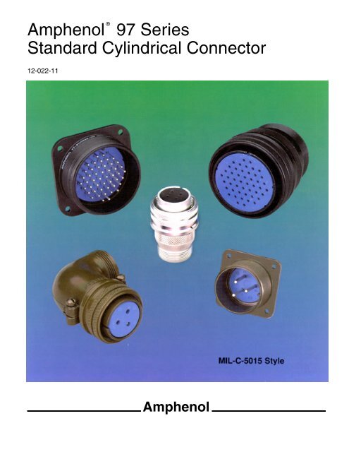
<strong>Amphenol</strong> <strong>97</strong> <strong>Series</strong><br />
<strong>Standard</strong> <strong>Cylindrical</strong> <strong>Connector</strong><br />
12-022-11<br />
<strong>Amphenol</strong><br />
MIL-C-5015 Style
This catalog covers the complete line of <strong>Amphenol</strong> ® <strong>97</strong> <strong>Series</strong> <strong>Connector</strong>s.<br />
It is divided into five sections: <strong>97</strong>E (Environmental), <strong>97</strong> <strong>Series</strong> solder, <strong>97</strong> <strong>Series</strong> crimp,<br />
special application connectors, and accessories:<br />
Table of Contents Page<br />
<strong>Amphenol</strong> ® <strong>97</strong> <strong>Series</strong> <strong>Standard</strong> <strong>Cylindrical</strong> <strong>Connector</strong>s – General Description. . . . . . . . . . . . . . . . . . . . . . . . . . . . . . . . . . . . . 1<br />
Guide to Selecting a <strong>Connector</strong> . . . . . . . . . . . . . . . . . . . . . . . . . . . . . . . . . . . . . . . . . . . . . . . . . . . . . . . . . . . . . . . . . . . . . . . . . 2<br />
<strong>Amphenol</strong> ® <strong>97</strong>E (Environmental) <strong>Series</strong> <strong>Connector</strong>s<br />
Design Features and Benefits. . . . . . . . . . . . . . . . . . . . . . . . . . . . . . . . . . . . . . . . . . . . . . . . . . . . . . . . . . . . . . . . . . . . . . . 3<br />
How to Order. . . . . . . . . . . . . . . . . . . . . . . . . . . . . . . . . . . . . . . . . . . . . . . . . . . . . . . . . . . . . . . . . . . . . . . . . . . . . . . . . . . . 4<br />
<strong>Amphenol</strong> ® <strong>97</strong> <strong>Series</strong> <strong>Connector</strong>s with Solder Contacts<br />
Design Characteristics, Customer Options . . . . . . . . . . . . . . . . . . . . . . . . . . . . . . . . . . . . . . . . . . . . . . . . . . . . . . . . . . . . . 5<br />
Insert Availability . . . . . . . . . . . . . . . . . . . . . . . . . . . . . . . . . . . . . . . . . . . . . . . . . . . . . . . . . . . . . . . . . . . . . . . . . . . . . . . 6, 7<br />
Contact Arrangements . . . . . . . . . . . . . . . . . . . . . . . . . . . . . . . . . . . . . . . . . . . . . . . . . . . . . . . . . . . . . . . . . . . . . . . . . .8-13<br />
Alternate Insert Positioning . . . . . . . . . . . . . . . . . . . . . . . . . . . . . . . . . . . . . . . . . . . . . . . . . . . . . . . . . . . . . . . . . . . . . . . . 14<br />
Receptacle Shell Styles . . . . . . . . . . . . . . . . . . . . . . . . . . . . . . . . . . . . . . . . . . . . . . . . . . . . . . . . . . . . . . . . . . . . . . . . . . 15<br />
Solid Shell Plug Styles . . . . . . . . . . . . . . . . . . . . . . . . . . . . . . . . . . . . . . . . . . . . . . . . . . . . . . . . . . . . . . . . . . . . . . . . . . . 16<br />
Split Shell Plug Styles . . . . . . . . . . . . . . . . . . . . . . . . . . . . . . . . . . . . . . . . . . . . . . . . . . . . . . . . . . . . . . . . . . . . . . . . . . . . 17<br />
Weight Reference Charts . . . . . . . . . . . . . . . . . . . . . . . . . . . . . . . . . . . . . . . . . . . . . . . . . . . . . . . . . . . . . . . . . . . . . . .18-20<br />
How to Order. . . . . . . . . . . . . . . . . . . . . . . . . . . . . . . . . . . . . . . . . . . . . . . . . . . . . . . . . . . . . . . . . . . . . . . . . . . . . . . . . . . 21<br />
<strong>Amphenol</strong> ® <strong>97</strong> <strong>Series</strong> <strong>Connector</strong>s with Rear Release Crimp Contacts<br />
Design Characteristics, Customer Options . . . . . . . . . . . . . . . . . . . . . . . . . . . . . . . . . . . . . . . . . . . . . . . . . . . . . . . . . . . . 22<br />
Specifications and Insert Availability, Alternate Insert Positioning . . . . . . . . . . . . . . . . . . . . . . . . . . . . . . . . . . . . . . . . . . 23<br />
Contact Arrangements . . . . . . . . . . . . . . . . . . . . . . . . . . . . . . . . . . . . . . . . . . . . . . . . . . . . . . . . . . . . . . . . . . . . . . . . 24, 25<br />
Receptacle Shell Styles . . . . . . . . . . . . . . . . . . . . . . . . . . . . . . . . . . . . . . . . . . . . . . . . . . . . . . . . . . . . . . . . . . . . . . . . . . 26<br />
Solid Shell Plug Styles . . . . . . . . . . . . . . . . . . . . . . . . . . . . . . . . . . . . . . . . . . . . . . . . . . . . . . . . . . . . . . . . . . . . . . . . . . . 27<br />
Split Shell Plug Styles . . . . . . . . . . . . . . . . . . . . . . . . . . . . . . . . . . . . . . . . . . . . . . . . . . . . . . . . . . . . . . . . . . . . . . . . . . . . 28<br />
How to Order. . . . . . . . . . . . . . . . . . . . . . . . . . . . . . . . . . . . . . . . . . . . . . . . . . . . . . . . . . . . . . . . . . . . . . . . . . . . . . . . . . . 29<br />
Crimp Contact Information . . . . . . . . . . . . . . . . . . . . . . . . . . . . . . . . . . . . . . . . . . . . . . . . . . . . . . . . . . . . . . . . . . . . . . . . 30<br />
Crimp Contact Information cont., Tools. . . . . . . . . . . . . . . . . . . . . . . . . . . . . . . . . . . . . . . . . . . . . . . . . . . . . . . . . . . . . . . 31<br />
Special Purpose <strong>Connector</strong>s<br />
Potting Construction . . . . . . . . . . . . . . . . . . . . . . . . . . . . . . . . . . . . . . . . . . . . . . . . . . . . . . . . . . . . . . . . . . . . . . . . . . . . . 32<br />
Box Type Plugs, Small Flange Receptacles . . . . . . . . . . . . . . . . . . . . . . . . . . . . . . . . . . . . . . . . . . . . . . . . . . . . . . . . . . . 33<br />
ECG <strong>Connector</strong>, Convenience Outlets . . . . . . . . . . . . . . . . . . . . . . . . . . . . . . . . . . . . . . . . . . . . . . . . . . . . . . . . . . . . . . . 34<br />
<strong>97</strong> <strong>Series</strong> Accessories<br />
Cable Clamps, Bushing. . . . . . . . . . . . . . . . . . . . . . . . . . . . . . . . . . . . . . . . . . . . . . . . . . . . . . . . . . . . . . . . . . . . . . . . 35, 36<br />
Protection Caps . . . . . . . . . . . . . . . . . . . . . . . . . . . . . . . . . . . . . . . . . . . . . . . . . . . . . . . . . . . . . . . . . . . . . . . . . . . . . 37, 38<br />
Adapters . . . . . . . . . . . . . . . . . . . . . . . . . . . . . . . . . . . . . . . . . . . . . . . . . . . . . . . . . . . . . . . . . . . . . . . . . . . . . . . . . . . . . . 39<br />
Conduit Box <strong>Connector</strong>, Conduit Coupling Nuts, . . . . . . . . . . . . . . . . . . . . . . . . . . . . . . . . . . . . . . . . . . . . . . . . . . . . . . . 40<br />
Sealing Gaskets . . . . . . . . . . . . . . . . . . . . . . . . . . . . . . . . . . . . . . . . . . . . . . . . . . . . . . . . . . . . . . . . . . . . . . . . . . . . . . . . 41<br />
Dummy Receptacles. . . . . . . . . . . . . . . . . . . . . . . . . . . . . . . . . . . . . . . . . . . . . . . . . . . . . . . . . . . . . . . . . . . . . . . . . . . . . 42<br />
Sales Office Listing<br />
<strong>Amphenol</strong> Aerospace is a Certified ISO 9001 Manufacturer.
®<br />
<strong>Amphenol</strong> <strong>97</strong> <strong>Series</strong> <strong>Connector</strong>s<br />
provide the interconnection solution for low cost,<br />
general duty and environmental applications<br />
<strong>Amphenol</strong> offers the <strong>97</strong> <strong>Series</strong> <strong>Connector</strong><br />
Family -<br />
A general duty standard cylindrical connector,<br />
MIL-C-5015 style, and the recent addition<br />
to the family - the <strong>97</strong>E Environmental<br />
style.<br />
The <strong>97</strong> <strong>Series</strong> is a widely used connector<br />
series for the automotive, robotics, machine<br />
tool and welding industries, as well as<br />
numerous other commercial applications<br />
from heavy equipment to ECG monitoring<br />
cables.<br />
Shell components are fabricated from high<br />
grade aluminum alloy to provide strength<br />
and environmental protection. This family of<br />
connectors offers a wide variety of shell<br />
styles, contact patterns and accessory<br />
options.<br />
The <strong>Amphenol</strong> ® <strong>97</strong> <strong>Series</strong> design features and benefits include:<br />
Low cost, general duty non-environmental<br />
or <strong>97</strong>E environmental styles<br />
Solder or crimp termination<br />
UL Recognized, CSA Recognized<br />
Wide selection of shell styles and insert patterns<br />
Wide selection of connector finishes -<br />
cadmium or non-cadmium (environmentally friendly zinc alloy)<br />
Threaded coupling, hard dielectric inserts<br />
Solid or split shell construction<br />
Accessories for both individual wire seal and jacketed cable<br />
For additional information on <strong>Amphenol</strong> ® <strong>97</strong> <strong>Series</strong> connectors, or for special application<br />
requirements, contact your local <strong>Amphenol</strong> sales office, authorized distributor, or -<br />
<strong>Amphenol</strong> Corporation<br />
<strong>Amphenol</strong> Aerospace<br />
40-60 Delaware Avenue<br />
Sidney, New York 13838-1395<br />
Telephone: 607-563-5011<br />
Fax: 607-563-5157<br />
Web site: www.<strong>Amphenol</strong>-Aerospace.com<br />
1
Guide to Selecting a <strong>Connector</strong><br />
In selecting a connector, it first must be<br />
determined if a non-environmental (<strong>97</strong><br />
A/B <strong>Series</strong>) type or an environmental<br />
(<strong>97</strong>E) type is required.<br />
Then the following 8 steps apply to<br />
formulation of a part number.*<br />
How many wires are you<br />
1 going to connect?<br />
What gauge?<br />
These two questions are important,<br />
because they indicate which insert you<br />
need. There are literally hundreds to<br />
choose from.<br />
The insert arrangements for solder<br />
contact connectors are illustrated on<br />
pages 8-13. The inserts most often<br />
used are highlighted on these pages.<br />
Here’s an example of how to choose<br />
an insert arrangement. Say you want to<br />
connect eight 16-ga. wires, - first find<br />
the section of arrangements containing<br />
8 contacts. Insert number 20-7 is<br />
the one you want because it contains<br />
eight 16-ga. contacts and it is one of<br />
the most often used. The one you<br />
choose might depend on your space or<br />
voltage requirements. The voltage<br />
capacity of each insert is listed under<br />
its diagram.<br />
If you have more than one wire size<br />
to connect, the method is essentially<br />
the same. Actually, the insert configurations<br />
for multiple-size wires are a lot<br />
more flexible than they appear. That’s<br />
because you can always solder a<br />
smaller wire to a larger contact. However,<br />
soldering a large wire to a small<br />
contact isn’t recommended because of<br />
size and current requirements.<br />
What if several identical<br />
2 connectors have different<br />
functions?<br />
Here’s a situation to watch out for. You<br />
have four identical receptacles on a<br />
panel. One carries high current loads.<br />
The others have low current functions.<br />
A plug mated with the wrong receptacle<br />
(cross-mating) could ruin your valuable<br />
equipment.<br />
To avoid cross-mating, you can<br />
order identical inserts positioned in<br />
both the plugs and receptacles at various<br />
angles from standard. These variations<br />
from standard position are called<br />
alternate insert positions, and are<br />
described on page 14.<br />
What kind of receptacle do<br />
3 you need?<br />
For Wall Mounting Use a wall receptacle,<br />
type 3100. The elongated back of<br />
this receptacle extends through thick<br />
wall material. It is threaded to accept<br />
standard hardware fittings.<br />
For Unmounted Applications Use<br />
the cable receptacle, type 3101.<br />
For Box or Panel Mounting Use the<br />
box receptacle, type 3102. This receptacle’s<br />
back is short to conserve space.<br />
It is not threaded on the back end and<br />
is used when no accessories such as<br />
clamps are needed.<br />
What kind of plug do you<br />
4 need?<br />
For ordinary situations The straight<br />
plug, type 3106 meets most connector<br />
requirements. However . . .<br />
when space is critical you may want<br />
to consider using an angle plug, type<br />
3108. This type plug lets the cable<br />
enter your equipment at a right angle.<br />
Do you need a plug with a<br />
5 Solid or Split back shell?<br />
You can get both straight and angle<br />
plugs in solid or split back shell<br />
designs. With the solid shell you have<br />
greater strength and you save space.<br />
On the other hand, the split shell<br />
design lets you quickly inspect the solder<br />
terminals when you need to. This<br />
feature could be important if you’ll be<br />
subjecting the connector to rough handling<br />
and heavy use.<br />
The designation to use for solid<br />
shell construction in an non-environmental<br />
type is the letter A. For a solid<br />
shell construction in the <strong>97</strong>E environmental<br />
sealing type the designation is<br />
E. This designation letter goes immediately<br />
after the main shell type number:<br />
for example, 3106A or 3108A.<br />
The designation for split shell construc-<br />
2<br />
tion is the letter B; for example, 3106B<br />
or 3108B. Split shell construction is<br />
available in non-environmental types<br />
only.<br />
Because of application, receptacles<br />
are made in solid backshell construction<br />
only. Their designation is 3100A/E,<br />
3101A/E. (See how to order for solder<br />
contact connectors, page 21, and how<br />
to order for <strong>97</strong>E on page 4).<br />
Which connector gets the<br />
6 socket? - the receptacle or<br />
the plug?<br />
You’re at the point where you designate<br />
which inserts are used with which<br />
shells. Either pin or socket inserts can<br />
be used with plugs or receptacles.<br />
Here’s a good rule of thumb. Order<br />
the sockets for the connector at the<br />
“hot” side of the circuit. By having sockets<br />
at the power source, there’s little<br />
chance that a wayward finger or screwdriver<br />
will short the circuit or cause personal<br />
injury.<br />
The designation for sockets is simply<br />
S in a part number, following the<br />
insert code number. For pins, the designation<br />
is P. Therefore, the 20-7P<br />
insert would have pin contacts, while<br />
the 20-7S insert would have socket<br />
contacts.<br />
What type of plating is pre-<br />
7 ferred?<br />
If you prefer the standard olive cadmium,<br />
non-reflective, electrically conductive<br />
finish, then no suffix number is<br />
required. Other plating variations are<br />
available, including environmentally<br />
friendly zinc alloy. See how to order<br />
instructions for the various plating finishes<br />
offered for <strong>97</strong> <strong>Series</strong> solder connectors<br />
on page 21, and for <strong>97</strong>E types<br />
on page 4.<br />
Do you need any<br />
8<br />
accessories?<br />
Accessories - cable clamps, protection<br />
caps and chains, conduit adapters, and<br />
panel gaskets are shown on pages 35-<br />
41.<br />
* These steps are for solder type connectors which are described in<br />
detail on pages 5-21. If a crimp type connector is needed, the same<br />
steps apply, however, you should consult pages 22-31 for details on<br />
<strong>97</strong> <strong>Series</strong> connectors with crimp contacts. And, for <strong>97</strong>E environmental<br />
type connectors, you should consult pages 3 and 4.
®<br />
<strong>Amphenol</strong> <strong>97</strong>E (environmental) series<br />
<strong>Connector</strong>s<br />
NEW DESIGN FROM AMPHENOL<br />
COMBINES AN ENVIRONMENTAL<br />
SERVICE CLASS WITH THE COST EFFEC-<br />
TIVE BENEFITS OF THE GENERAL DUTY<br />
<strong>97</strong> SERIES<br />
<strong>Amphenol</strong>, continuing to meet the needs of<br />
today’s interconnection products marketplace,<br />
now offers the <strong>97</strong>E (Environmental)<br />
<strong>Series</strong> . . . . .<br />
Incorporating a sealing gasket in the plug<br />
and standard use of environmental backshell<br />
accessories to provide a low cost,<br />
general duty, and environmentally sealed<br />
connector.<br />
The <strong>Amphenol</strong> ® <strong>97</strong>E <strong>Series</strong> connector can be<br />
used in a variety of industrial applications<br />
where environmental sealing is required,<br />
such as:<br />
Automotive<br />
Robotics<br />
Machine Tool<br />
Welding Equipment<br />
The <strong>Amphenol</strong> ® <strong>97</strong>E <strong>Series</strong> provides environmental<br />
sealing in the mated condition when<br />
used with the proper rear accessory hardware.<br />
Environmental sealing is accomplished<br />
with the addition of a sealing gasket<br />
in the plug interface and standard use of environmental,<br />
MIL-C-5015 type “E” backshell<br />
accessories. This includes a grommet for<br />
individual wire sealing and a backshell with<br />
clamp bars to provide axial strain relief. If the<br />
application requires the use of jacketed cable, a standard<br />
deviation, (290), in the part number callout can provide<br />
the M85049/2 type cable clamp. (See how to order information<br />
on the back side of this sheet). The incorporation<br />
of these environmental accessories will prevent moisture<br />
from entering the rear of the connector.<br />
The <strong>97</strong>E (Environmental) <strong>Series</strong> is offered by <strong>Amphenol</strong><br />
with the same wide variety of shell styles and insert<br />
arrangements that are available in the <strong>97</strong> <strong>Series</strong>, the<br />
proven, industry standard.<br />
L-2089 assembly instructions for <strong>97</strong>E is available. Consult<br />
<strong>Amphenol</strong>, Sidney, NY for copies.<br />
<strong>Amphenol</strong> <strong>97</strong>E (Environmental) <strong>Series</strong> for Individual Wire Sealing<br />
<strong>Amphenol</strong> <strong>97</strong>E (Environmental) <strong>Series</strong> for use with Jacketed Cable<br />
Features of <strong>Amphenol</strong> ® <strong>97</strong>E (Environmental) <strong>Series</strong><br />
<strong>Connector</strong>s with MIL-C-5015 style insert arrangements:<br />
Environmental sealing through use of<br />
Sealing gaskets<br />
MIL-C-5015 E/F backshells<br />
Low cost, general duty, environmental<br />
Solder or crimp termination<br />
Crimp applications apply to jacketed cable only (290 suffix)<br />
Wide selection of shell styles and insert patterns<br />
Wide selection of platings - cadmium or environmentally<br />
friendly zinc alloy<br />
Threaded coupling, hard dielectric inserts<br />
Intermateable and intermountable with existing <strong>97</strong> <strong>Series</strong><br />
3
<strong>97</strong>E (environmental) series<br />
how to order<br />
Example of part number for environmental <strong>97</strong>E <strong>Series</strong> connectors is given below.<br />
(For non-environmental solder type connectors how to order, see pg. 21, and for non-environmental crimp type connectors how to order, see pg. 29).<br />
<strong>Series</strong> Number<br />
<strong>97</strong> - Like MS, but<br />
<strong>Amphenol</strong> ®<br />
Shell Type<br />
3100 Wall Mount Receptacle<br />
3101 In-Line Cable Receptacle<br />
3106 Straight Plug<br />
4100* Wall Mount Receptacle (Crimp)<br />
4101* In-line Cable Receptacle (Crimp)<br />
4106* Straight Plug (Crimp)<br />
<strong>Connector</strong> Class<br />
E designates Environmental<br />
Shell Size<br />
10SL, 12, 12S, 14, 14S, 16, 16S, 18, 20, 22, 24, 28<br />
32, 36<br />
Insert Arrangement<br />
Refer to insert availability listing and illustrations,<br />
pages 6-13 for solder type, and pages 23-25 for<br />
crimp type.<br />
Consult <strong>Amphenol</strong>, Sidney, NY for most current<br />
insert availability in environmental series.<br />
* <strong>97</strong>E crimp is available for jacketed cable only, and must use the<br />
290 deviation<br />
L-2089 assembly instructions for <strong>97</strong>E connectors are available<br />
upon request.<br />
<strong>97</strong> – 3106 E – 28 – 21 S Y (290) (621)<br />
4<br />
Shell Finish<br />
Omit for standard O. D.<br />
Cadmium finish<br />
(621) black zinc alloy<br />
(624) green zinc alloy<br />
(608) black anodize<br />
(640) conductive black zinc alloy<br />
(689) electroless nickel<br />
Deviation<br />
(290) designates backshell for use with<br />
jacketed cable<br />
Consult <strong>Amphenol</strong>, Sidney, N.Y. for<br />
additional deviations<br />
Alternate Position<br />
W, X, Y or Z<br />
Omit for standard position<br />
Contact Style<br />
P - designates pin contacts<br />
S - designates socket contacts
®<br />
<strong>Amphenol</strong> <strong>97</strong> <strong>Series</strong> <strong>Connector</strong>s<br />
with solder contacts<br />
MS3100A<br />
MS3101A<br />
MS3102A<br />
MS3106A<br />
MS3106B<br />
MS3107A<br />
MS3107B<br />
MS3108A<br />
MS3108B<br />
5<br />
DESIGN CHARACTERISTICS<br />
Medium to heavy weight cylindrical<br />
Durable, field-proven design<br />
Environmental resistant<br />
Single key/keyway polarization<br />
Threaded coupling, hard dielectric inserts<br />
Operating temperatures from –55°C to +125°C<br />
Cost effective<br />
Intermateable and intermountable with existing<br />
<strong>97</strong> <strong>Series</strong> and MIL-C-5015 connectors<br />
Underwriters Laboratories approved recognition<br />
File E1154<strong>97</strong><br />
Canadian <strong>Standard</strong>s Association Certification<br />
File LR69183<br />
CUSTOMER OPTIONS<br />
Solid or split shell construction<br />
Six shell styles<br />
128 contact arrangements, from 1 to 52 circuits<br />
Alternate insert positioning<br />
High temperature and potting constructions<br />
Special plating finishes including black and<br />
green zinc alloy<br />
Optional gold plating on MS contacts<br />
Thermocouple arrangements available<br />
<strong>97</strong>E available for jacketed cable and individual<br />
wire seal applications<br />
<strong>Connector</strong> components are fabricated from high grade<br />
aluminum alloy, with a conductive cadmium plate finish<br />
and an olive drab chromate after-treatment. Some cable<br />
clamps are a zinc alloy with an olive drab/green chromate<br />
finish. See how to order page 21 for other finish variations.<br />
Contacts are silver plated with pre-tinned solder cups.<br />
Optional gold over silver plating is also available. Inserts<br />
for solder style contacts are diallyl-phthalate.<br />
Users should be aware that classes “A” and “B” of MIL-C-<br />
5015 have been cancelled, and these products are no<br />
longer qualified.
<strong>97</strong> series solder type<br />
insert availability<br />
Insert Number<br />
Total<br />
Contacts<br />
Mechanical<br />
Spacing Service<br />
Contact Size<br />
Rating<br />
Inches mm 0 4 8 12 16<br />
8S-1F 1 1/16 1.57 INST. 1<br />
10SL-3 3 1/16 1.57 A 3<br />
10SL-4 2 1/16 1.57 A 2<br />
12SL-844F* 4 1/16 1.57 A 4<br />
12S-3 2 1/16 1.57 A 2<br />
12-5F 1 1/8 3.18 D 1<br />
12S-6F* 2 1/16 1.57<br />
2<br />
Thermocouple<br />
14S-1† 3 1/16 1.57 A 3<br />
14S-2 4 INST. 4<br />
14S-4F† 1 1/8 3.18 D 1<br />
14S-5 5 INST 5<br />
14S-6 6 INST. 6<br />
14S-7 3 1/16 1.57 A 3<br />
14S-9† 2 1/16 1.57 A 2<br />
16S-1 7 1/16 1.57 A 7<br />
16S-4F 2 1/8 3.18 D 2<br />
16S-5 3 1/16 1.57 A 3<br />
16S-6F† 3 1/16 1.57 A 3<br />
16-7 3 1/16 1.57 A 1 2<br />
16S-8 5 1/16 1.57 A 5<br />
16-9 4 1/16 1.57 A 2 2<br />
16-10 3 1/16 1.57 A 3<br />
16-11F† 2 1/16 1.57 A 2<br />
16-12 1 1/16 1.57 A 1<br />
16-13 2 1/16 1.57 A<br />
2<br />
Thermocouple<br />
18-1 10 1/16 1.57<br />
A<br />
INST.<br />
4<br />
6<br />
18-3† 2 1/8 3.18 D 2<br />
18-4 4 1/8 3.18 D 4<br />
18-5F 3 1/8 3.18 D 2 1<br />
18-8 8 1/16 1.57 A 1 7<br />
18-9F 7 INST. 2 5<br />
18-10† 4 1/16 1.57 A 4<br />
18-11 5 1/16 1.57 A 5<br />
18-12† 6 1.16 1.57 A 6<br />
18-13 4 1/16 1.57 A 1 3<br />
18-16 1 5/16 7.92 C 1<br />
18-19† 10 1/16 1.57 A 10<br />
18-20 5 1/16 1.57 A 5<br />
18-22† 3 1/8 3.18 D 3<br />
18-29F† 5 1/16 1.57 A 5<br />
18-420* 1<br />
1<br />
Hi-Voltage**<br />
20-3† 3 1/8 3.18 D 3<br />
6<br />
Insert Number<br />
Total<br />
Contacts<br />
Mechanical<br />
Spacing<br />
Inches mm<br />
Service<br />
Rating<br />
0 4<br />
Contact Size<br />
8 12 16<br />
20-4 4 1/8 3.18 D 4<br />
20-6† 3 1/8 3.18 D 3<br />
20-7 8<br />
1/8<br />
1/16<br />
3.18<br />
1.57<br />
D<br />
A<br />
4<br />
4<br />
20-8 6 INST. 2 4<br />
20-11† 13 INST. 13<br />
20-14 5 1/16 1.57 A 2 3<br />
20-15 7 1/16 1.57 A 7<br />
20-16 9 1/16 1.57 A 2 7<br />
20-17 6 1/16 1.57 A 5 1<br />
20-18 9 1/16 1.57 A 3 6<br />
20-19† 3 1/16 1.57 A 3<br />
20-21 9 1/16 1.57 A 1 8<br />
20-23 2 1/16 1.57 A 2<br />
20-24 4 1/16 1.57 A 2 2<br />
20-27 14 1/16 1.57 A 14<br />
20-29 17 1/16 1.57 A 17<br />
20-33 11 1/16 1.57 A 11<br />
22-1† 2 1/8 3.18 D 2<br />
22-2 3 1/8 3.18 D 3<br />
22-4† 4 1/16 1.57 A 2 2<br />
22-5 6 1/8 3.18 D 2 4<br />
22-8† 2 3/16 4.75 E 2<br />
22-9 3 3/16 4.75 E 3<br />
22-10 4 3/16 4.75 E 4<br />
22-11 2 1/4 6.35 B 2<br />
22-12 5 1/8 3.18 D 2 3<br />
22-13† 5<br />
1/8<br />
1/16<br />
3.18<br />
1.57<br />
D<br />
A 4<br />
1<br />
22-14 19 1/16 1.57 A 19<br />
22-15 6<br />
3/16<br />
1/16<br />
4.75<br />
1.57<br />
E<br />
A 5<br />
1<br />
22-16† 9 1/16 1.57 A 3 6<br />
22-18 8<br />
1/8<br />
1/16<br />
3.18<br />
1.57<br />
D<br />
A<br />
5<br />
3<br />
22-19 14 1/16 1.57 A 14<br />
22-20† 9 1/16 1.57 A 9<br />
22-22 4 1/16 1.57 A 4<br />
22-23 8<br />
1/8 3.18 D 1<br />
1/16 1.57 A 7<br />
Not all insert arrangements are currently available for environmental individual<br />
wire seal. Consult <strong>Amphenol</strong>, Sidney, NY for availability.<br />
† Inactive for new military design, but available for replacement or for non-military<br />
purposes.<br />
* “MS” number not assigned. Use “<strong>97</strong>” prefix in place of “MS” in completing catalog<br />
number. See how to order, page 21.<br />
** Hi-Voltage = 17KVAC/24KVDC<br />
F Molded-in pin (MIP) insert requires (910) deviation. See how to order, pg. 21.
<strong>97</strong> series solder type<br />
insert availability, cont.<br />
Insert<br />
Number<br />
Total<br />
Contacts<br />
Mechanical<br />
Spacing Service<br />
Contact Size<br />
Rating<br />
Inches mm 0 4 8 12 16<br />
22-26* 7 1/8 3.18 2 5<br />
22-27 9<br />
1/8<br />
1/16<br />
3.18<br />
1.57<br />
D<br />
A<br />
1<br />
8<br />
22-28† 7 1/16 1.57 A 7<br />
22-34 5 1/8 3.18 D 3 2<br />
24-2 7 1/8 3.18 D 7<br />
24-5† 16 1/16 1.57 A 16<br />
24-6 8<br />
1/8<br />
1/16<br />
3.18<br />
1.57<br />
D<br />
A<br />
3<br />
5<br />
24-7 16 1/16 1.57 A 2 14<br />
24-9† 2 1/16 1.57 A 2<br />
24-10 7 1/16 1.57 A 7<br />
24-11 9 1/16 1.57 A 3 6<br />
24-12 5 1/16 1.57 A 2 3<br />
24-16 7<br />
1/8<br />
1/16<br />
3.18<br />
1.57<br />
D<br />
A<br />
1<br />
3<br />
3<br />
24-19† 12 1/16 1.57 12<br />
24-20F 11 1/8 3.18 D 2 9<br />
24-21 10 1/8 3.18 D 1 9<br />
24-22F 4 1/8 3.18 D 4<br />
24-27 7 3/16 4.75 E 7<br />
24-28 24 1/16 1.57 INST. 24<br />
28-1 9<br />
1/8<br />
1/16<br />
3.18<br />
1.57<br />
D<br />
A<br />
1<br />
2<br />
2<br />
4<br />
28-2 14 1/8 3.18 D 2 12<br />
28-3 3 3/16 4.75 E 3<br />
28-6† 3 1/8 3.18 D 3<br />
1/16 1.57 A 9<br />
28-8 12 1/8 3.18 D 1<br />
3/16 4.75 E 2<br />
28-9 12 1/8 3.18 D 6 6<br />
28-10 7<br />
1/8<br />
1/16<br />
3.18<br />
1.57<br />
D<br />
A 2 2<br />
1<br />
2<br />
28-11 22 1/16 1.57 A 4 18<br />
28-12 26 1/16 1.57 A 26<br />
28-15† 35 1/16 1.57 A 35<br />
28-16† 20 1/16 1.57 A 20<br />
28-17 15<br />
28-18 12<br />
28-19 10<br />
1/4 6.35 B 1<br />
1/8 3.18 D 3<br />
1/16 1.57 A 11<br />
5/16 7.92 C 1<br />
1/8 3.18 D 5<br />
1/16 1.57 A 2<br />
INST. 4<br />
1/4 6.35 B 2<br />
1/8 3.18 D 2<br />
1/16 1.57 A 4 2<br />
7<br />
Insert<br />
Number<br />
Total<br />
Contacts<br />
Mechanical<br />
Spacing<br />
Inches mm<br />
Service<br />
Rating<br />
0 4<br />
Contact Size<br />
8 12 16<br />
28-20 14 1/16 1.57 A 10 4<br />
28-21 37 1/16 1.57 A 37<br />
32-5† 2 1/8 3.18 D 2<br />
32-6 23 1/16 1.57 A 2 3 2 16<br />
32-7 35<br />
1/16 1.57 A<br />
INST.<br />
7 24<br />
4<br />
32-8† 30 1/16 1.57 A 6 24<br />
32-13 23 1/8 3.18 D 5 18<br />
32-17 4 1/8 3.18 D 4<br />
32-414 52 1/16 1.57 A 52<br />
36-1† 22 1/8 3.18 D 4 18<br />
36-5 4 1/16 1.57 A 4<br />
36-6 6 1/16 1.57 A 2 4<br />
36-7 47 1/16 1.57 A 7 40<br />
36-8 47 1/16 1.57 A 1 46<br />
36-9 31 1/16 1.57 A 1 2 14 14<br />
36-10 48 1/16 1.57 A 48<br />
36-15 35<br />
1/16<br />
1/8<br />
1.57<br />
3.18<br />
A<br />
D<br />
34<br />
1<br />
36-403* 52 1/16 1.57 A 52<br />
Not all insert arrangements are currently available for environmental individual<br />
wire seal. Consult <strong>Amphenol</strong>, Sidney, NY for availability.<br />
† Inactive for new military design, but available for replacement or for non-military<br />
purposes.<br />
* “MS” number not assigned. Use “<strong>97</strong>” prefix in place of “MS” in completing catalog<br />
number. See how to order, page 21.<br />
F Molded-in pin (MIP) insert requires (910) deviation. See how to order, pg. 21.
<strong>97</strong> series solder type<br />
insert arrangements<br />
Front view of pin insert or rear of socket insert illustrated.<br />
Items highlighted are most popular and most readily available.<br />
NOTE: Not all insert arrangements are currently available for environmental, individual wire seal. Consult <strong>Amphenol</strong>, Sidney, NY for availability.<br />
1 Contact<br />
Insert Arrangement 8S-1 12-5 14S-4† 16-12 18-16 18-420*<br />
Contacts 1#16 1#12 1#16 1#4 1#12 1#12<br />
Service Rating INST. D D A C High Voltage<br />
17KVAC/24KVDC<br />
2 Contacts<br />
Insert Arrangement 10SL-4 12S-3 12S-6* 14S-9† 16S-4 16-11† 16-13<br />
Contacts 2#16 2#16 2#16 2#16 2#16 2#12 2#12<br />
Service Rating A A Thermocouple A D A A<br />
Insert Arrangement 18-3† 20-23† 22-1† 22-8† 22-11 24-9† 32-5†<br />
Contacts 2#12 2#8 2#8 2#12 2#16 2#4 2#0<br />
Service Rating D A D E B A D<br />
3 Contacts<br />
Insert Arrangement 10SL-3 14S-1† 14S-7 16S-5† 16S-6† 16-7 16-10 18-5 18-22†<br />
Contacts 3#16 3#16 3#16 3#16 3#16 1#8, 2#16 3#12 2#12, 1#16 3#16<br />
Service Rating A A A A A A A D D<br />
Insert Arrangement 20-3† 20-6† 20-19† 22-2 22-9 28-3 28-6†<br />
Contacts 3#12 3#16 3#8 3#8 3#12 3#8 3#4<br />
Service Rating D D A D E E D<br />
8
<strong>97</strong> series solder type<br />
insert arrangements, cont.<br />
Front view of pin insert or rear of socket insert illustrated.<br />
Items highlighted are most popular and most readily available.<br />
NOTE: Not all insert arrangements are currently available for environmental, individual wire seal. Consult <strong>Amphenol</strong>, Sidney, NY for availability.<br />
4 Contacts<br />
Insert Arrangement 12SL-844* 14S-2† 16-9 18-4 18-10† 18-13 20-4<br />
Contacts 4#16 4#16 2#12, 2#16 4#16 4#12 3#12, 1#8 4#12<br />
Service Rating 1/16” spacing INST. A D A A D<br />
Insert Arrangement 20-24 22-4† 22-10 22-22 24-22 32-17 36-5<br />
Contacts 2#8, 2#16 2#8, 2#12 4#16 4#8 4#8 4#4 4#0<br />
Service Rating A A E A D D A<br />
5 Contacts<br />
Insert Arrangement 14S-5 16S-8 18-11 18-20† 18-29† 20-14<br />
Contacts 5#16 5#16 5#12 5#16 5#16 3#12, 2#8<br />
Service Rating INST. A A A A A<br />
Insert Arrangement 22-12 22-13† 22-34† 24-12<br />
Contacts 2#8, 3#16 1#16, 4#12 3#12, 2#16 2#4, 3#12<br />
Service Rating D E = D; A, B, C, D = A D A<br />
SERVICE RATING<br />
INST. A D E B C<br />
Limiting Operating DC 250 700 1250 1750 2450 4200<br />
Voltages at Sea Level AC (rms) 200 500 900 1250 1750 3000<br />
See notes 1 and 2 under TEST CURRENT.<br />
INST. service normally for low voltage and currents.<br />
Effective Creepage (nominal) Inch 1/16 1/8 3/16 1/4 5/16 1<br />
mm 1.57 3.18 4.75 6.35 7.92 25.40<br />
Mechanical Spacing (nominal) Inch 1/16 1/8 3.16 1/4 5/16<br />
mm 1.57 3.18 4.75 6.35 7.92<br />
† Inactive for new military design, but available for replacement or for<br />
non-military purposes.<br />
* “MS” number not assigned. Use “<strong>97</strong>” prefix in place of “MS” in completing<br />
catalog number. See how to order, page 21.<br />
9<br />
TEST CURRENT<br />
Contact Size 16 12 8 4 0<br />
Amperes 13 23 46 80 150<br />
NOTE 1: Transients were not considered in calculating<br />
these values.<br />
NOTE 2: Limiting operating voltages at 50,000 feet altitude<br />
are approximately 25% of the sea level<br />
values.<br />
CONTACT LEGEND<br />
16 12 8 4 0 16 12 16 12<br />
IRON CONSTANTAN
<strong>97</strong> series solder type<br />
insert arrangements, cont.<br />
Front view of pin insert or rear of socket insert illustrated.<br />
Items highlighted are most popular and most readily available.<br />
NOTE: Not all insert arrangements are currently available for environmental, individual wire seal. Consult <strong>Amphenol</strong>, Sidney, NY for availability.<br />
6 Contacts<br />
Insert Arrangement 14S-6 18-12† 20-8 20-17 22-5 22-15 36-6<br />
Contacts 6#16 6#16 4#16, 2#8 5#12, 1#16 2#12, 4#16 5#12, 1#16 2#0, 4#4<br />
Service Rating INST. A INST. A D D = E; A, B, C, E, F = A A<br />
7 Contacts<br />
Insert Arrangement 16S-1 18-9 20-15 22-26* 22-28†<br />
Contacts 7#16 5#16, 2#12 7#12 2#12, 5#16 7#12<br />
Service Rating A INST. A 1/8” spacing A<br />
Insert Arrangement 24-2 24-10 24-16 24-27 28-10<br />
Contacts 7#12 7#8 3#16, 1#8, 3#12 7#16 3#12, 2#8, 2#4<br />
Service Rating D A A, B, F, G = D; E G = D; all others = A<br />
C, D, E = A<br />
8 Contacts<br />
Insert Arrangement 18-8 20-7 22-18 22-23 24-6<br />
Contacts 1#12, 7#16 8#16 8#16 8#12 8#12<br />
Service Rating A A, B, H, G = D; A, B, H, F, G = D; H = D; A, G, H = D;<br />
C, D, E, F = A all others = A all others = A all others - A<br />
10
<strong>97</strong> series solder type<br />
insert arrangements, cont.<br />
Front view of pin insert or rear of socket insert illustrated.<br />
Items highlighted are most popular and most readily available.<br />
NOTE: Not all insert arrangements are currently available for environmental, individual wire seal. Consult <strong>Amphenol</strong>, Sidney, NY for availability.<br />
9 Contacts<br />
Insert Arrangement 20-16 20-18 20-21 22-16† 22-20†<br />
Contacts 7#16, 2#12 3#12, 6#16 1#12, 8#16 3#12, 6#16 9#16<br />
Service Rating A A A A A<br />
Insert Arrangement 22-27 24-11 28-1<br />
Contacts 1#8, 8#16 3#8, 6#12 3#8, 6#12<br />
Service Rating J = D; all others = A A A, J, E = D; all others = A<br />
10 Contacts 11 Contacts<br />
Insert Arrangement 18-1 18-19 24-21 28-19 20-33 24-20<br />
Contacts 10#16 10#16 1#8, 9#16 4#12, 6#16 11#16 2#12, 9#16<br />
Service Rating B, C, F, G = A; A D H, M = B; A, B = D; A D<br />
all others = INST. all others = A<br />
12 Contacts 13 Contacts<br />
Insert Arrangement 24-19† 28-8 28-9 28-18 20-11†<br />
Contacts 12#16 2#12, 10#16 6#12, 6#16 12#16 13#16<br />
Service Rating 1/16” spacing L, M = E; B = D; D M = C; A, B = A INST.<br />
all others = A C, D, E, F = INST.; all others = D<br />
† Inactive for new military design, but available for replacement or for<br />
non-military purposes.<br />
* “MS” number not assigned. Use “<strong>97</strong>” prefix in place of “MS” in completing<br />
catalog number. See how to order, page 21.<br />
See Service Rating and Test Current information on page 9.<br />
11<br />
CONTACT LEGEND<br />
16 12 8 4 0
<strong>97</strong> series solder type<br />
insert arrangements, cont.<br />
Front view of pin insert or rear of socket insert illustrated.<br />
Items highlighted are most popular and most readily available.<br />
NOTE: Not all insert arrangements are currently available for environmental, individual wire seal. Consult <strong>Amphenol</strong>, Sidney, NY for availability.<br />
14 Contacts 15 Contacts<br />
Insert Arrangement 20-27 22-19 28-2 28-20 28-17<br />
Contacts 14#16 14#16 2#12, 12#16 10#12, 4#16 15#16<br />
Service Rating A A D A R = B; M, N, P = D;<br />
all others = A<br />
16 Contacts 17 Contacts 19 Contacts<br />
Insert Arrangement 24-5† 24-7 20-29 22-14<br />
Contacts 16#16 2#12, 14#16 17#16 19#16<br />
Service Rating A A A A<br />
20 Contacts 22 Contacts 23 Contacts<br />
Insert Arrangement 28-16† 28-11 36-1† 32-6 32-13<br />
Contacts 20#16 4#12, 18#16 4#12, 18#16 2#4, 3#8, 2#12, 16#16 5#12, 18#16<br />
Service Rating A A D A D<br />
24 Contacts 26 Contacts 30 Contacts 31 Contacts<br />
Insert Arrangement 24-28 28-12 32-8† 36-9<br />
Contacts 24#16 26#16 6#12, 24#16 1#4, 2#8, 14#12, 14#16<br />
Service Rating INST. A A A<br />
12
<strong>97</strong> series solder type<br />
insert arrangements, cont.<br />
Front view of pin insert or rear of socket insert illustrated.<br />
Items highlighted are most popular and most readily available.<br />
NOTE: Not all insert arrangements are currently available for environmental, individual wire seal. Consult <strong>Amphenol</strong>, Sidney, NY for availability.<br />
35 Contacts 37 Contacts<br />
Insert Arrangement 28-15† 32-7 36-15 28-21<br />
Contacts 35#16 7#12, 28#16 35#16 37#16<br />
Service Rating A A, B, h, j = INST.; m = D; all others = A A<br />
all others = A<br />
47 Contacts 48 Contacts<br />
Insert Arrangement 36-7 36-8 36-10<br />
Contacts 7#12, 40#16 1#12, 46#16 48#16<br />
Service Rating A A A<br />
52 Contacts<br />
Insert Arrangement 32-414* 36-403*<br />
Contacts 52#16 52#16<br />
Service Rating A A<br />
† Inactive for new military design, but available for replacement or for<br />
non-military purposes.<br />
* “MS” number not assigned. Use “<strong>97</strong>” prefix in place of “MS” in completing<br />
catalog number. See how to order, page 21.<br />
See Service Rating and Test Current information on page 9.<br />
13<br />
CONTACT LEGEND<br />
16 12 8 4 0
14<br />
<strong>97</strong> series solder type<br />
alternate insert positioning<br />
Insert<br />
Arrangement<br />
Degrees<br />
W X Y Z<br />
12S-3 70 145 215 290<br />
14S-2<br />
14S-5<br />
14S-7<br />
14S-9<br />
–<br />
–<br />
90<br />
70<br />
120<br />
110<br />
180<br />
145<br />
240<br />
–<br />
270<br />
215<br />
–<br />
–<br />
–<br />
290<br />
16S-1<br />
16S-4<br />
16S-5<br />
16S-6<br />
16-7<br />
16S-8<br />
16-9<br />
16-10<br />
16-11<br />
16-13<br />
80<br />
35<br />
70<br />
90<br />
80<br />
–<br />
35<br />
90<br />
35<br />
35<br />
–<br />
110<br />
145<br />
180<br />
110<br />
170<br />
110<br />
180<br />
110<br />
110<br />
–<br />
250<br />
215<br />
270<br />
250<br />
265<br />
250<br />
270<br />
250<br />
250<br />
280<br />
325<br />
290<br />
–<br />
280<br />
–<br />
325<br />
–<br />
325<br />
325<br />
18-1<br />
18-3<br />
18-4<br />
18-5<br />
18-8<br />
18-9<br />
18-10<br />
18-11<br />
18-12<br />
18-13<br />
18-19<br />
18-20<br />
18-22<br />
18-29<br />
70<br />
35<br />
35<br />
80<br />
70<br />
80<br />
–<br />
–<br />
80<br />
80<br />
–<br />
90<br />
70<br />
90<br />
145<br />
110<br />
110<br />
110<br />
–<br />
110<br />
120<br />
170<br />
–<br />
110<br />
120<br />
180<br />
145<br />
180<br />
215<br />
250<br />
250<br />
250<br />
–<br />
250<br />
240<br />
265<br />
–<br />
250<br />
240<br />
270<br />
215<br />
270<br />
290<br />
325<br />
325<br />
280<br />
290<br />
280<br />
–<br />
–<br />
280<br />
280<br />
–<br />
–<br />
290<br />
–<br />
20-3<br />
20-4<br />
20-6<br />
20-7<br />
20-8<br />
20-14<br />
20-15<br />
20-16<br />
20-17<br />
20-18<br />
20-19<br />
20-21<br />
20-23<br />
20-24<br />
20-27<br />
20-29<br />
70<br />
45<br />
70<br />
80<br />
80<br />
80<br />
80<br />
80<br />
90<br />
35<br />
90<br />
35<br />
35<br />
35<br />
35<br />
80<br />
145<br />
110<br />
145<br />
110<br />
110<br />
110<br />
–<br />
110<br />
180<br />
110<br />
180<br />
110<br />
110<br />
110<br />
110<br />
–<br />
215<br />
250<br />
215<br />
250<br />
250<br />
250<br />
–<br />
250<br />
270<br />
250<br />
270<br />
250<br />
250<br />
250<br />
250<br />
–<br />
290<br />
–<br />
290<br />
280<br />
280<br />
280<br />
280<br />
280<br />
–<br />
325<br />
–<br />
325<br />
325<br />
325<br />
325<br />
280<br />
*Rotates opposite above illustration.<br />
22-1<br />
22-2<br />
22-4<br />
22-5<br />
22-8<br />
22-9<br />
22-10<br />
22-11<br />
22-12<br />
22-13<br />
22-14<br />
22-15<br />
22-16<br />
22-18<br />
22-19<br />
22-20<br />
22-22<br />
22-23<br />
22-27<br />
22-28<br />
22-34<br />
35<br />
70<br />
35<br />
35<br />
35<br />
70<br />
35<br />
35<br />
80<br />
35<br />
80<br />
80<br />
80<br />
80<br />
80<br />
35<br />
–<br />
35<br />
80<br />
80<br />
80<br />
110<br />
145<br />
110<br />
110<br />
110<br />
145<br />
110<br />
110<br />
110<br />
110<br />
110<br />
110<br />
110<br />
110<br />
110<br />
110<br />
110<br />
–<br />
–<br />
–<br />
110<br />
250<br />
215<br />
250<br />
250<br />
250<br />
215<br />
250<br />
250<br />
250<br />
250<br />
250<br />
250<br />
250<br />
250<br />
250<br />
250<br />
250<br />
250<br />
250<br />
–<br />
250<br />
325<br />
290<br />
325<br />
325<br />
325<br />
290<br />
325<br />
325<br />
280<br />
325<br />
280<br />
280<br />
280<br />
280<br />
280<br />
325<br />
–<br />
–<br />
280<br />
280<br />
280<br />
24-2<br />
24-5<br />
24-6<br />
24-7<br />
24-9<br />
24-10<br />
24-11<br />
24-12<br />
24-16<br />
24-20<br />
24-21<br />
24-22<br />
24-27<br />
24-28<br />
80<br />
80<br />
80<br />
80<br />
35<br />
80<br />
35<br />
80<br />
80<br />
80<br />
80<br />
45<br />
80<br />
80<br />
–<br />
110<br />
110<br />
110<br />
110<br />
–<br />
110<br />
110<br />
110<br />
110<br />
110<br />
110<br />
–<br />
110<br />
–<br />
250<br />
250<br />
250<br />
250<br />
–<br />
250<br />
250<br />
250<br />
250<br />
250<br />
250<br />
–<br />
250<br />
280<br />
280<br />
280<br />
280<br />
325<br />
280<br />
325<br />
280<br />
280<br />
280<br />
280<br />
–<br />
280<br />
280<br />
28-1<br />
28-2<br />
28-3<br />
28-6<br />
28-8<br />
28-9<br />
28-10<br />
28-11<br />
28-12<br />
28-15<br />
28-16<br />
28-17<br />
28-18<br />
28-19<br />
28-20<br />
28-21<br />
80<br />
35<br />
70<br />
70<br />
80<br />
80<br />
80<br />
80<br />
90<br />
80<br />
80<br />
80<br />
70<br />
80<br />
80<br />
80<br />
110<br />
110<br />
145<br />
145<br />
110<br />
110<br />
110<br />
110<br />
180<br />
110<br />
110<br />
110<br />
145<br />
110<br />
110<br />
110<br />
250<br />
250<br />
215<br />
215<br />
250<br />
250<br />
250<br />
250<br />
270<br />
250<br />
250<br />
250<br />
215<br />
250<br />
250<br />
250<br />
280<br />
325<br />
290<br />
290<br />
280<br />
280<br />
280<br />
280<br />
–<br />
280<br />
280<br />
280<br />
290<br />
280<br />
280<br />
280<br />
32-5<br />
32-6<br />
32-7<br />
32-8<br />
32-13<br />
32-17<br />
32-414*<br />
35<br />
80<br />
80<br />
80<br />
80<br />
45<br />
80*<br />
110<br />
110<br />
125<br />
125<br />
110<br />
110<br />
110*<br />
250<br />
250<br />
235<br />
235<br />
250<br />
250<br />
250*<br />
325<br />
280<br />
280<br />
280<br />
280<br />
–<br />
280*<br />
36-1<br />
36-5<br />
36-6<br />
36-7<br />
36-8<br />
36-9<br />
36-10<br />
36-15<br />
80<br />
–<br />
35<br />
80<br />
80<br />
80<br />
80<br />
60<br />
110<br />
120<br />
110<br />
110<br />
110<br />
125<br />
125<br />
125<br />
250<br />
240<br />
250<br />
250<br />
250<br />
235<br />
235<br />
245<br />
280<br />
–<br />
325<br />
280<br />
280<br />
280<br />
280<br />
305<br />
Insert<br />
Arrangement<br />
Degrees<br />
W X Y Z<br />
FRONT FACE OF PIN INSERT
<strong>97</strong> series solder type<br />
receptacles<br />
MS3100A wall mount receptacle<br />
Solid shell construction is strong and conserves<br />
space. Includes integral polarizing<br />
key in front. Back shell is threaded for standard<br />
MS/AN fittings.<br />
MS3100A and MS3101A<br />
<strong>Connector</strong><br />
Size<br />
A<br />
Coupling<br />
Thread<br />
MS3101A cable receptacle<br />
Solid shell construction is strong and conserves<br />
space. Includes integral polarizing key<br />
in front shell. Machined back shell is threaded<br />
for standard MS/AN fittings. Can be<br />
unscrewed for inspection or soldering.<br />
15<br />
MS3102A box receptacle<br />
Solid shell designed for open wiring. Mounts<br />
directly on chassis, equipment or panel.<br />
Includes internal polarized key in front shell.<br />
K Ref. L Max. M Ref. N Ref. O Ref. R Ref. S Ref.<br />
V<br />
Fitting Threads<br />
Inch mm Inch mm Inch mm Inch mm Inch mm Inch mm Inch mm<br />
8S 1/2-28 5/64 1.98 1-1/4 31.75 9/16 14.27 17/32 13.49 .562 14.27 19/32 15.06 7/8 22.23 1/2-28<br />
10S 5/8-24 5/64 1.98 1-5/16 33.32 9/16 14.27 5/8 15.88 .688 17.48 23/32 18.24 1 25.40 1/2-28<br />
10SL 5/8-24 5/64 1.98 1-9/32 32.53 9/16 14.27 3/4 19.05 .812 20.62 23/32 18.24 1 25.40 5/8-24<br />
12S 3/4-20 5/64 1.98 1-15/32 37.29 9/16 14.27 25/32 19.84 .812 20.62 13/16 20.62 1-3/32 27.76 5/8-24<br />
12 3/4-20 5/64 1.98 1-27/32 46.81 3/4 19.05 25/32 19.84 .812 20.62 13/16 20.62 1-3/32 27.76 5/8-24<br />
14S 7/8-20 5/64 1.98 1-15/32 37.39 9/16 14.27 7/8 22.23 .938 23.83 29/32 23.01 1-3/16 30.15 3/4-20<br />
14 7/8-20 5/64 1.98 1-55/64 47.04 3/4 19.05 7/8 22.23 .938 23.83 29/32 23.01 1-3/16 30.15 3/4-20<br />
16S 1 -20 5/64 1.98 1-15/32 37.39 9/16 14.27 1 25.40 1.062 26.<strong>97</strong> 31/32 24.59 1-9/32 32.54 7/8-20<br />
16 1 -20 1/8 3.18 1-57/64 47.85 3/4 19.05 1 25.40 1.062 26.<strong>97</strong> 31/32 24.59 1-9/32 32.54 7/8-20<br />
18 1-1/8-18 1/8 3.18 1-63/64 50.24 3/4 19.05 1-1/8 28.58 1.188 30.18 1-1/16 26.<strong>97</strong> 1-3/8 34.93 1 -20<br />
20 1-1/4-18 1/8 3.18 1-57/64 47.85 3/4 19.05 1-1/4 31.75 1.312 33.32 1-5/32 29.36 1-1/2 38.10 1-3/16-18<br />
22 1-3/8-18 1/8 3.18 1-63/64 50.24 3/4 19.05 1-3/8 34.93 1.438 36.53 1-1/4 31.75 1-5/8 39.67 1-3/16-18<br />
24 1-1/2-18 1/8 3.18 2-1/4 57.15 13/16 20.62 1-1/2 38.10 1.562 36.67 1-3/8 34.43 1-3/4 44.45 1-7/16-18<br />
28 1-3/4-18 1/8 3.18 2-1/4 57.15 13/16 20.62 1-3/4 44.45 1.812 46.02 1-9/16 39.67 2 50.80 1-7/16-18<br />
32 2 -18 1/8 3.18 2-3/8 60.33 7/8 22.23 2-1/32 51.59 2.062 52.37 1-3/4 44.45 2-1/4 57.15 1-3/4-18<br />
36 2-1/4-16 1/8 3.18 2-3/8 60.33 7/8 22.23 2-1/4 57.15 2.312 58.72 1-15/16 49.20 2-1/2 63.50 2 -18<br />
MS3102A<br />
Connect A<br />
K Ref. L Max. M Ref. N Ref. O Ref. R Ref. S Ref.<br />
or<br />
Size<br />
Coupling<br />
Thread Inch mm Inch mm Inch mm Inch mm Inch mm Inch mm Inch mm<br />
8S 1/2-28 5/64 1.98 55/64 21.82 9/16 14.27 7/16 11.10 .562 14.27 19/32 15.06 7/8 22.23<br />
10S 5/8-24 5/64 1.98 55.64 21.82 9/16 14.27 1/2 12.70 .688 17.48 23/32 18.24 1 25.40<br />
10SL 5/8-24 5/64 1.98 61.64 24.21 35/64 13.87 11/16 17.48 .812 20.62 23/32 18.24 1 25.40<br />
12S 3/4-20 5/64 1.98 31/32 24.61 9/16 14.27 11/16 17.45 .812 20.62 13/16 20.62 1-3/32 27.76<br />
12 3/4-20 5/64 1.98 1-21/64 33.73 3/4 19.05 11/16 17.45 .812 20.62 13/16 20.62 1-3/32 27.76<br />
12SL 3/4-20 5/64 1.98 27/32 21.44 35/64 13.87 11/16 17.45 .938 23.83 13/16 20.62 1-3/32 27.76<br />
14S 7/8-20 5/64 1.98 61/64 24.21 9/16 14.27 3/4 19.05 .938 23.83 29/32 23.01 1-3/16 30.15<br />
14 7/8-20 5/64 1.98 1-11/32 34.14 3/4 19.05 3/4 19.05 .938 23.83 29/32 23.01 1-3/16 30.15<br />
16S 1 -20 5/64 1.98 61/64 24.21 9/16 14.27 7/8 22.23 1.062 26.<strong>97</strong> 31/32 24.59 1-9/32 32.54<br />
16 1 -20 1/8 3.18 1-3/8 34.92 3/4 19.05 7/8 22.23 1.062 26.<strong>97</strong> 31/32 24.59 1-9/32 32.54<br />
18 1-1/8-18 1/8 3.18 1-3/8 34.92 3/4 19.05 1 25.40 1.188 30.18 1-1/16 26.<strong>97</strong> 1-3/8 34.93<br />
20 1-1/4-18 1/8 3.18 1-3/8 34.92 3/4 19.05 1-1/8 28.58 1.312 33.32 1-5/32 29.36 1-1/2 38.10<br />
22 1-3/8-18 1/8 3.18 1-3/8 34.92 3/4 19.05 1-1/4 31.75 1.438 36.53 1-1/4 31.75 1-5/8 41.28<br />
24 1-1/2-18 1/8 3.18 1-3/8 34.92 13/16 20.62 1-3/8 34.93 1.562 39.67 1-3/8 34.93 1-3/4 44.45<br />
28 1-3/4-18 1/8 3.18 1-3/8 34.92 13/16 20.62 1-5/8 41.28 1.812 46.02 1-9/16 39.67 2 50.80<br />
32 2 -18 1/8 3.18 1-15/32 37.31 7/8 22.23 1-29/32 48.41 2.062 52.37 1-3/4 44.45 2-1/4 57.15<br />
36 2-1/4-18 1/8 3.18 1-15/32 37.31 7/8 22.23 2-1/8 53.98 2.312 58.72 1-15/16 49.20 2-1/2 63.50
<strong>97</strong> series solder type<br />
plugs with solid shells<br />
MS3106A<br />
<strong>Connector</strong><br />
Size<br />
L Max. N Ref. Q Max. V<br />
Fitting Threads<br />
Inch mm Inch mm Inch mm<br />
8S 1-1/4 31.75 17/32 13.49 3/4 19.05 1/2-28<br />
10S 1-5/16 33.32 5/8 15.88 7/8 22.23 1/2-28<br />
10SL 1-3/8 34.93 3/4 19.05 7/8 22.23 5/8-24<br />
12S 1-7/16 36.50 25/32 19.84 1 25.40 5/8-24<br />
12 1-7/8 47.63 25/32 19.84 1 25.40 5/8-24<br />
12SL 1-31/64 37.69 7/8 22.23 1 25.40 3/4-20<br />
14S 1-15/32 37.13 7/8 22.23 1-1/8 28.58 3/4-20<br />
14 1-7/8 47.47 7/8 22.23 1-1/8 28.58 3/4-20<br />
16S 1-15/32 37.13 1 25.40 1-1/4 31.75 7/8-20<br />
16 1-7/8 47.47 1 25.40 1-1/4 31.75 7/8-20<br />
18 1-31/32 49.88 1-1/8 28.57 1-11/32 34.11 1 -20<br />
20 1-7/8 47.50 1-1/4 31.75 1-15/32 37.29 1-3/16-18<br />
22 1-31/32 49.88 1-3/8 34.93 1-19/32 40.46 1-3/16-18<br />
24 2-1/4 57.15 1-1/2 38.10 1-23/32 43.64 1-7/16-18<br />
28 2-1/4 57.15 1-3/4 44.45 1-31/32 49.99 1-7/16-18<br />
32 2-3/8 60.33 2-1/32 51.59 2-7/32 56.34 1-3/4-18<br />
36 2-3/8 60.33 2-1/4 57.15 2-15/32 62.69 2 -18<br />
MS3107A<br />
<strong>Connector</strong> L Max. N Ref. Q Max. V<br />
Size Inch mm Inch mm Inch mm Fitting Threads<br />
10S 1-5/16 33.32 5/8 15.88 7/8 22.23 1/2-28<br />
10SL 1-3/8 34.92 3/4 19.05 7/8 22.23 5/8-24<br />
12S 1-7/16 36.50 25/32 19.84 1 25.40 5/8-24<br />
12 1-7/8 47.63 25/32 19.84 1 25.40 5/8-24<br />
14S 1-15/32 37.13 7/8 22.23 1-1/8 38.58 3/4-20<br />
14 1-7/8 47.47 7/8 22.23 1-1/8 28.58 3/4-20<br />
16S 1-15/32 37.13 1 25.40 1-1/4 31.75 7/8-20<br />
16 1-7/8 47.47 1 25.40 1-1/4 31.75 7/8-20<br />
18 1-31/32 49.88 1-1/8 28.58 1-11/32 34.11 1 -20<br />
20 1-7/8 47.50 1-1/4 31.75 1-15/32 37.29 1-3/16-18<br />
22 1-31/32 49.88 1-3/8 34.93 1-19/32 40.46 1-3/16-18<br />
24 2-1/4 57.15 1-1/2 38.10 1-23/32 43.64 1-7/16-18<br />
28 2-1/4 57.15 1-3/4 44.45 1-31/32 49.99 1-7/16-18<br />
MS3108A<br />
<strong>Connector</strong> L Ref. Q Max. U Ref. V<br />
Y Ref.<br />
Size Inch mm Inch mm Inch mm Fitting Threads Inch mm<br />
10S 1-1/4 31.75 7/8 22.23 7/8 22.23 1/2-28 25/32 19.84<br />
10SL 1-5/16 33.32 7/8 22.23 1 25.40 5/8-24 1-1/16 26.<strong>97</strong><br />
12S 1-3/8 34.93 1 25.40 1 25.40 5/8-24 1-1/16 26.<strong>97</strong><br />
12SL 1-3/8 34.93 1 25.40 1 25.40 3/4-20 1-1/16 26.<strong>97</strong><br />
12 1-13/64 30.56 1 25.40 1 25.40 5/8-24 1-1/16 26.<strong>97</strong><br />
14S 1-3/8 34.93 1-1/8 28.58 1 25.40 3/4-20 1-1/16 26.<strong>97</strong><br />
14 1-13/16 46.02 1-1/8 28.58 1 25.40 3/4-20 1-1/16 26.<strong>97</strong><br />
16S 1-1/2 38.10 1-1/4 31.75 1-1/8 28.58 7/8-20 1-5/16 33.32<br />
16 1-15/16 49.20 1-1/4 31.75 1-1/8 28.58 7/8-20 1-5/16 33.32<br />
18 1-15/16 49.20 1-11/32 34.11 1-1/8 28.58 1 -20 1-5/16 33.32<br />
20 2-1/16 52.37 1-15/32 37.29 1-5/16 33.32 1-3/16-18 1-5/8 42.28<br />
22 2-1/16 52.37 1-19/32 40.46 1-5/16 33.32 1-3/16-18 1-5/8 42.28<br />
24 2-15/32 62.69 1-23/32 43.64 1-1/2 38.10 1-7/16-18 2 50.80<br />
28 2-15/32 62.69 1-31/32 49.99 1-1/2 38.10 1-7/16-18 2 50.80<br />
16<br />
MS3106A straight plug<br />
Sturdy, simple to assemble. Coupling ring<br />
machined from solid aluminum bar stock for<br />
high tensile strength. Mates with all types of<br />
MS receptacles. Front shell includes polarizing<br />
keyway. Back shell is threaded for standard<br />
MS/AN fittings.<br />
MS3107A quick-disconnect plug<br />
For fast connect/disconnect applications.<br />
Front shell has polarizing keyway. Mates<br />
with all types of MS receptacles. Back shell<br />
is threaded for standard MS/AN fittings<br />
MS3108A angle plug<br />
For use where space in front of panel or wall<br />
is at a premium. Swivel ring and plate combination<br />
allow cable take off at any angle relative<br />
to front shell polarizing key. Back shell<br />
is threaded for standard MS/AN fittings.
<strong>97</strong> series solder type<br />
plugs with split shells<br />
MS3106B<br />
<strong>Connector</strong><br />
L Max. Q Max. V<br />
Y Ref.<br />
Size Inch mm Inch mm Fitting Threads Inch mm<br />
14S 1-11/16 42.85 1-1/8 28.58 3/4-20 1-5/32 29.36<br />
16S 1-11/16 42.85 1-1/4 31.75 7/8-20 1-1/4 31.75<br />
18 2-1/16 52.37 1-11/32 34.11 1 -20 1-41/64 41.66<br />
20 2-1/8 53.98 1-15/32 37.29 1-3/16-18 1-13/16 46.02<br />
22 2-1/8 53.98 1-19/32 40.46 1-3/16-18 1-15/16 49.20<br />
24 2-9/32 57.94 1-23/32 43.64 1-7/16-18 2-1/16 52.37<br />
28 2-9/32 57.94 1-31/32 49.99 1-7/16-18 2-5/16 58.72<br />
32 2-5/16 58.72 2-7/32 56.34 1-3/4-18 2-19/32 65.86<br />
36 2-11/32 59.51 2-15/32 62.69 2 -18 2-27/32 72.21<br />
MS3107B<br />
<strong>Connector</strong><br />
L Max. Q Max. V<br />
Y Ref.<br />
Size Inch mm Inch mm Fitting Threads Inch mm<br />
14S 1-11/16 42.85 1-1/8 28.58 3/4-20 1-5/32 29.36<br />
16S 1-11/16 42.85 1-1/4 31.75 7/8-20 1-1/4 31.75<br />
18 2-1/16 52.37 1-11/32 34.11 1 -20 1-41/64 41.66<br />
20 2-1/8 53.99 1-15/32 37.29 1-3/16-18 1-13/16 46.02<br />
22 2-1/8 53.99 1-19/32 40.46 1-3/16-18 1-15/16 49.20<br />
24 2-9/32 57.94 1-23/32 43.64 1-7/16-18 2-1/16 52.37<br />
28 2-9/32 57.94 1-31/32 49.99 1-7/16-18 2-5/16 58.72<br />
MS3108B<br />
<strong>Connector</strong> L Ref. Q Max. U Ref. V<br />
X Ref.<br />
Size Inch mm Inch mm Inch mm Fitting Threads Inch mm<br />
10S 1-3/8 34.93 7/8 22.23 7/8 22.23 1/2-28<br />
10SL 1-1/2 38.10 7/8 22.23 1 25.40 5/8-24<br />
12S 1-9/16 39.67 1 25.40 1 25.40 5/8-24 1/2 12.70<br />
12 1-7/8 47.63 1 25.40 1 25.40 5/8-24 1/2 12.70<br />
14S 1-23/32 43.64 1-1/8 28.58 1-1/16 26.<strong>97</strong> 3/4-20 21/32 16.66<br />
14 1-15/16 49.20 1-1/8 28.58 1-1/16 26.<strong>97</strong> 3/4-20 21/32 16.66<br />
16S 1-3/4 44.45 1-1/4 31.75 1-1/8 28.58 7/8-20 1-1/2 38.10<br />
16 2-1/8 53.98 1-1/4 31.75 1-1/8 28.58 7/8-20 1-1/2 38.10<br />
18 2-5/32 54.75 1-11/32 34.11 1-3/16 30.15 1 -20 1-41/64 41.66<br />
20 2-3/8 60.33 1-15/32 37.29 1-5/16 33.32 1-3/16-18 1-13/16 46.02<br />
22 2-13/32 61.11 1-19/32 40.46 1-5/16 33.32 1-3/16-18 1-15/16 49.20<br />
24 2-5/8 66.68 1-23/32 43.64 1-7/16 36.50 1-7/16-18 2-1/16 52.37<br />
28 2-5/8 66.68 1-31/32 49.99 1-7/16 36.50 1-7/16-18 2-5/16 58.72<br />
32 2-13/16 71.42 2-7/32 56.34 1-3/4 44.45 1-3/4-18 2-19/32 65.86<br />
36 2-27/32 72.21 2-15/32 62.69 1-15/16 49.20 2 -18 2-27/32 72.21<br />
17<br />
MS3106B straight plug<br />
Used for unusual conduit applications where<br />
soldering and inspection is the prime requirement.<br />
Back shell is threaded for all standard<br />
MS/AN fittings.<br />
MS3107B quick-disconnect plug<br />
For fast connect/disconnect applications. Front<br />
shell has polarizing keyway. Mates with all types<br />
of MS receptacles. Back shell is threaded for<br />
standard MS/AN fittings<br />
MS3108B angle plug<br />
Lightweight, roomy cavity, split longitudinally for<br />
convenient solder or inspection. Front shell is<br />
keyed to allow the 90° angle housing to be<br />
rotated and locked at any 45° increment.<br />
Sizes 10S thru 14<br />
Sizes 16S thru 40
<strong>97</strong> series solder type<br />
availability and weight reference<br />
Wall<br />
Receptacles<br />
MS3100<br />
Cable<br />
Receptacles<br />
MS3101<br />
Box<br />
Receptacles<br />
MS3102<br />
Straight Plugs<br />
MS3106<br />
18<br />
Quick Disconnect<br />
Plugs MS3107<br />
Angle Plugs<br />
MS3108<br />
Insert Solid Shell Solid Shell Solid Shell Solid Shell Split Shell Solid Shell Split Shell Solid Shell Split Shell Total<br />
Number<br />
A A A A B A B A B<br />
Contacts<br />
8S-1 .02 .01 .01 .02 1<br />
10SL-3P .03 .03 .02 3<br />
10SL-3S .03 .03 .06 .05 3<br />
10SL-4P† .02 .02 .02 2<br />
10SL-4S† .03 .03 .06 .05 2<br />
12S-3 .04 .03 .03 .03 .03 .07 .07 2<br />
12-5 .05 .04 .03 .06 .06 .09 .08 1<br />
12S-6* .04 .03 .03 .04 .04 .07 .08 2<br />
12SL-844P* .03 4<br />
12SL-844S* .05 .06 .08 4<br />
14S-1† .05 .04 .03 .06 .06 .06 .06 .08 .08 3<br />
14S-2 .05 .04 .03 .06 .06 .06 .06 .08 .08 4<br />
14S-4† .05 .04 .03 .06 .06 .06 .06 .08 .08 1<br />
14S-5 .05 .04 .04 .06 .06 .06 .06 .08 .08 5<br />
14S-6 .05 .04 .04 .06 .06 .06 .06 .08 .08 6<br />
14S-7 .05 .04 .03 .06 .06 .06 .06 .08 .08 3<br />
14S-9† .05 .04 .03 .06 .06 .07 .06 .08 .08 2<br />
16S-1 .06 .05 .05 .07 .07 .08 .07 .14 .11 7<br />
16S-4 .06 .05 .04 .07 .07 .07 .07 .12 .10 2<br />
16S-5† .06 .05 .04 .07 .07 .07 .07 .12 .10 3<br />
16S-6† .06 .05 .04 .07 .07 .09 .07 .12 .10 3<br />
16-7 .08 .08 .07 .09 .07 .15 .14 3<br />
16S-8 .06 .05 .04 .07 .07 .09 .07 .12 .10 5<br />
16-9 .08 .07 .09 .09 .10 .12 .13 4<br />
16-10 .08 .08 .07 .09 .09 .15 .14 3<br />
16-11† .08 .07 .07 .09 .11 .14 .13 2<br />
16-12 .10 .09 .08 .11 .08 .16 .15 1<br />
16-13 .07 .07 .06 .08 .11 .14 .13 2<br />
18-1 .10 .10 .08 .11 .13 .12 .13 .16 .15 10<br />
18-3† .10 .10 .08 .12 .13 .11 .13 .16 .15 2<br />
18-4 .09 .09 .07 .11 .13 .12 .13 .16 .15 4<br />
18-5 .10 .10 .08 .12 .13 .13 .13 .16 .15 3<br />
18-8 .10 .10 .08 .12 .14 .12 .14 .16 .15 8<br />
18-9 .11 .10 .09 .12 .14 .13 .14 .17 .16 7<br />
18-10† .11 .09 .13 .14 .13 .14 .17 .16 4<br />
18-11 .11 .11 .09 .13 .15 .11 .15 .18 .17 5<br />
18-12† .10 .09 .08 .11 .13 .13 .13 .16 .15 6<br />
18-13 .12 .12 .10 .13 .15 .13 .15 .18 .17 4<br />
18-16 .09 .09 .07 .11 .13 .11 .13 .15 .14 1<br />
18-19† .10 .10 .08 .11 .13 .11 .13 .16 .15 10<br />
18-20† .09 .09 .07 .11 .13 .11 .13 .15 .15 5<br />
18-22† .09 .09 .07 .11 .13 .13 .16 .15 3<br />
18-29† .10 .08 .11 .13 .11 .13 .16 .15 5<br />
18-420†* .10 .10 .08 .12 .13 .12 .13 .16 .16 1<br />
20-3† .14 .13 .10 .15 .16 .15 .16 .24 .19 3<br />
Where no weight is shown, insert is not available in that shell type.<br />
† Inactive for new military design, but available for replacement or for nonmilitary<br />
purposes.<br />
* “MS” number not assigned. Use “<strong>97</strong>” prefix in place of “MS” in completing<br />
catalog number.<br />
Weights are for connectors with socket contacts.<br />
<strong>Connector</strong>s with pin contacts weigh slightly less.<br />
If a weight appears in the column, the shell is available.<br />
Weight is shown in lbs.
<strong>97</strong> series solder type<br />
availability and weight reference, cont.<br />
Wall<br />
Receptacles<br />
MS3100<br />
Cable<br />
Receptacles<br />
MS3101<br />
Box<br />
Receptacles<br />
MS3102<br />
Straight Plugs<br />
MS3106<br />
19<br />
Quick Disconnect<br />
Plugs MS3107<br />
Angle Plugs<br />
MS3108<br />
Insert Solid Shell Solid Shell Solid Shell Solid Shell Split Shell Solid Shell Split Shell Solid Shell Split Shell Total<br />
Number<br />
A A A A B A B A B<br />
Contacts<br />
20-4 .14 .13 .10 .15 .16 .15 .16 .24 .19 4<br />
20-6† .12 .11 .09 .13 .15 .14 .15 .23 .18 3<br />
20-7 .13 .12 .09 .14 .15 .14 .15 .23 .18 8<br />
20-8 .15 .14 .12 .16 .18 .16 .18 .26 .20 6<br />
20-11† .14 .13 .11 .15 .17 .15 .17 .25 .20 13<br />
20-14 .16 .15 .13 .17 .19 .17 .19 .27 .21 5<br />
20-15 .15 .14 .12 .16 .18 .16 .18 .26 .21 7<br />
20-16 .14 .13 .10 .15 .16 .15 .16 .24 .19 9<br />
20-17 .15 .14 .11 .16 .17 .16 .17 .25 .20 6<br />
20-18 .14 .13 .11 .15 .17 .15 .17 .25 .19 9<br />
20-19† .16 .15 .13 .17 .19 .17 .19 .27 .21 3<br />
20-21 .13 .12 .10 .14 .16 .14 .16 .24 .19 9<br />
20-23† .15 .14 .11 .16 .17 .16 .17 .25 .20 2<br />
20-24 .15 .14 .11 .16 .17 .16 .17 .25 .20 4<br />
20-27 .13 .12 .10 .14 .16 .14 .16 .24 .19 14<br />
20-29 .14 .13 .11 .15 .17 .15 .17 .25 .20 17<br />
20-33 .13 .12 .09 .14 .18 .18 .18 .23 .18 11<br />
22-1† .16 .16 .13 .18 .19 .18 .19 .27 .23 2<br />
22-2 .17 .17 .14 .19 .20 .19 .20 .29 .24 3<br />
22-4† .21 .17 .14 .19 .20 .19 .20 .28 .23 4<br />
22-5 .15 .14 .12 .17 .18 .17 .18 .26 .21 6<br />
22-8† .15 .14 .11 .16 .18 .16 .18 .26 .21 2<br />
22-9 .15 .15 .12 .17 .18 .17 .18 .26 .21 3<br />
22-10 .14 .13 .10 .15 .17 .15 .17 .25 .20 4<br />
22-11 .14 .13 .10 .15 .17 .15 .17 .25 .20 2<br />
22-12 .16 .16 .13 .18 .19 .18 .19 .27 .23 5<br />
22-13† .16 .15 .12 .17 .18 .17 .18 .27 .22 5<br />
22-14 .15 .14 .11 .16 .18 .16 .18 .26 .21 19<br />
22-15 .16 .14 .13 .17 .19 .17 .19 .27 .22 6<br />
22-16† .16 .15 .12 .17 .18 .17 .18 .27 .22 9<br />
22-18 .14 .13 .10 .15 .17 .15 .17 .25 .20 8<br />
22-19 .15 .14 .11 .16 .18 .16 .18 .26 .21 14<br />
22-20† .14 .14 .11 .16 .17 .16 .17 .25 .21 9<br />
22-22 .19 .19 .16 .21 .26 .21 .22 .30 .25 4<br />
22-23 .17 .16 .13 .18 .20 .18 .20 .28 .23 8<br />
22-26† .15 .14 .11 .19 7<br />
22-27 .15 .15 .12 .17 .18 .17 .18 .27 .22 9<br />
22-28† .17 .16 .13 .18 .20 .18 .20 .28 .23 7<br />
22-34† .15 .15 .12 .17 .18 .17 .18 .26 .22 5<br />
24-2 .20 .19 .16 .22 .24 .22 .24 .39 .29 7<br />
24-5† .18 .17 .14 .20 .22 .20 .22 .37 .27 16<br />
24-6 .20 .19 .16 .22 .24 .22 .27 .39 .29 8<br />
24-7 .19 .18 .14 .21 .23 .21 .23 .38 .27 16<br />
24-9† .22 .21 .17 .24 .25 .24 .25 .41 .30 2<br />
24-10 .26 .25 .21 .28 .30 .28 .30 .45 .34 7<br />
Where no weight is shown, insert is not available in that shell type.<br />
† Inactive for new military design, but available for replacement or for nonmilitary<br />
purposes.<br />
* “MS” number not assigned. Use “<strong>97</strong>” prefix in place of “MS” in completing<br />
catalog number.<br />
Weights are for connectors with socket contacts.<br />
<strong>Connector</strong>s with pin contacts weigh slightly less.<br />
If a weight appears in the column, the shell is available.<br />
Weight is shown in lbs.
<strong>97</strong> series solder type<br />
availability and weight reference, cont.<br />
Wall<br />
Receptacles<br />
MS3100<br />
Cable<br />
Receptacles<br />
MS3101<br />
Box<br />
Receptacles<br />
MS3102<br />
Straight Plugs<br />
MS3106<br />
20<br />
Quick Disconnect<br />
Plugs MS3107<br />
Angle Plugs<br />
MS3108<br />
Insert Solid Shell Solid Shell Solid Shell Solid Shell Split Shell Solid Shell Split Shell Solid Shell Split Shell Total<br />
Number<br />
A A A A B A B A B<br />
Contacts<br />
24-11 .24 .22 .19 .26 .27 .26 .27 .43 .32 9<br />
24-12 .23 .22 .19 .25 .27 .25 .27 .42 .32 5<br />
24-16 .20 .19 .15 .22 .24 .22 .24 .39 .28 7<br />
24-19† .18 .17 .13 .20 .22 .37 .36 12<br />
24-20 .19 .17 .14 .21 .22 .21 .22 .38 .27 11<br />
24-21 .19 .17 .14 .21 .23 .21 .23 .38 .27 10<br />
24-22 .22 .21 .18 .24 .26 .24 .26 .41 .30 4<br />
24-27 .17 .16 .13 .20 .21 .20 .21 .36 .26 7<br />
24-28 .19 .18 .14 .21 .22 .21 .22 .38 .27 24<br />
28-1 .29 .27 .24 .30 .32 .30 .32 .44 .36 9<br />
28-2 .24 .22 .19 .25 .27 .25 .27 .40 .32 14<br />
28-3 .26 .24 .21 .28 .30 .28 .30 .42 .34 3<br />
28-6† .30 .28 .25 .31 .33 .31 .33 .45 .38 3<br />
28-8 .23 .22 .18 .25 .27 .25 .27 .39 .31 12<br />
28-9 .25 .24 .20 .27 .29 .27 .29 .41 .33 12<br />
28-10 .31 .29 .26 .33 .35 .33 .35 .47 .39 7<br />
28-11 .25 .24 .20 .27 .29 .27 .29 .41 .33 22<br />
28-12 .24 .22 .19 .26 .28 .26 .28 .40 .32 26<br />
28-15† .25 .23 .20 .26 .28 .26 .28 .40 .32 35<br />
28-16† .24 .22 .19 .25 .27 .25 .27 .39 .31 20<br />
28-17 .23 .22 .18 .25 .27 .25 .27 .39 .31 15<br />
28-18 .23 .22 .18 .25 .27 .25 .27 .39 .31 12<br />
28-19 .24 .22 .19 .26 .28 .26 .28 .40 .32 10<br />
28-20 .27 .25 .22 .29 .31 .29 .31 .43 .35 14<br />
28-21 .25 .23 .20 .26 .28 .26 .28 .40 .32 37<br />
32-5† .36 .35 .32 .38 .40 .48 2<br />
32-6 .39 .38 .35 .41 .43 .51 23<br />
32-7 .33 .33 .29 .36 .38 .45 35<br />
32-8† .32 .32 .29 .35 .37 .44 30<br />
32-13 .32 .31 .28 .34 .36 .44 23<br />
32-17 .37 .37 .34 .40 .42 .49 4<br />
32-414† .35 .35 .31 .38 .40 .48 52<br />
36-1† .41 .39 .34 .41 .43 .52 22<br />
36-5 .54 .52 .47 .54 .56 .65 4<br />
36-6 .55 .53 .49 .55 .57 .67 6<br />
36-7 .44 .41 .37 .44 .45 .55 47<br />
36-8 .40 .38 .34 .41 .42 .52 47<br />
36-9 .50 .47 .43 .50 .51 .61 31<br />
36-10 .41 .39 .34 .41 .43 .53 48<br />
36-15 .40 .37 .38 .40 .41 .51 35<br />
36-403†* .40 .36 .33 .40 .41 .51 52<br />
Where no weight is shown, insert is not available in that shell type.<br />
† Inactive for new military design, but available for replacement or for nonmilitary<br />
purposes.<br />
* “MS” number not assigned. Use “<strong>97</strong>” prefix in place of “MS” in completing<br />
catalog number.<br />
Weights are for connectors with socket contacts.<br />
<strong>Connector</strong>s with pin contacts weigh slightly less.<br />
If a weight appears in the column, the shell is available.<br />
Weight is shown in lbs.
<strong>97</strong> series solder type<br />
how to order<br />
Example of part number for non-environmental solder type connectors is given below.<br />
(For environmental solder type connectors, see how to order on page 4).<br />
<strong>Series</strong> Number<br />
<strong>97</strong> - Like MS but<br />
<strong>Amphenol</strong> ®<br />
Shell Type<br />
3100 Wall Receptacle<br />
3101 Cable Receptacle<br />
3102 Box Receptacle<br />
3106 Straight Plug<br />
3107 Quick Disconnect Plug<br />
3108 Angle Plug<br />
Shell Construction<br />
A - Solid Backshell<br />
B - Split Backshell<br />
Shell Size<br />
8S, 10SL, 12S, 14S, 14, 16S, 16<br />
18, 20, 22, 24, 28, 32, 36, 40<br />
Insert Configuration Number<br />
See insert availability listing - pages 6 & 7,<br />
and see insert arrangement illustrations -<br />
pages 8-13.<br />
Note: Accessories for <strong>97</strong> <strong>Series</strong> <strong>Connector</strong>s<br />
should be ordered with matching connector<br />
plating. See accessory pages 35-41.<br />
<strong>97</strong> – 3101 A – 28 – 21 S Y (847) (639)<br />
21<br />
Shell Finish<br />
Omit for standard O.D.<br />
cadmium finish<br />
(604) Gray anodized<br />
(608) Black anodized<br />
(621) Black zinc alloy<br />
(624) Green zinc alloy<br />
(639) Clear cadmium<br />
(640) Conductive black zinc alloy<br />
(689) Electroless nickel<br />
Deviation from standard A&B<br />
construction<br />
Omit this suffix if standard construction is<br />
desired<br />
(115) Small flange receptacle<br />
(426) Gold over silver plating on contacts<br />
(438) Construction for potting (see page<br />
31 for additional deviations)<br />
(936) <strong>Connector</strong> plug with safety wire<br />
holes in coupling nut<br />
Consult <strong>Amphenol</strong>, Sidney, NY for<br />
other deviations.<br />
Alternate Insert Positions<br />
Omit for standard position<br />
W, X, Y or Z for alternate positions,<br />
depending on insert (see page 14 for<br />
positions available)<br />
Contact Type<br />
P = Pin<br />
S = Socket
®<br />
<strong>Amphenol</strong> <strong>97</strong> <strong>Series</strong> <strong>Connector</strong>s<br />
with rear release crimp contacts<br />
<strong>97</strong>-4100A<br />
<strong>97</strong>-4101A<br />
<strong>97</strong>-4102A<br />
<strong>97</strong>-4106A<br />
<strong>97</strong>-4106B<br />
<strong>97</strong>-4107A<br />
<strong>97</strong>-4107B<br />
<strong>97</strong>-4108A<br />
<strong>97</strong>-4108B<br />
22<br />
DESIGN CHARACTERISTICS<br />
Rugged metal shell<br />
Conductive finish<br />
Stamped & formed crimp contacts<br />
Closed entry socket contacts<br />
Plastic retention<br />
Utilizes standard <strong>97</strong> <strong>Series</strong> hardware<br />
Intermateable and intermountable with existing<br />
<strong>97</strong> <strong>Series</strong> and MIL-C-5015 connectors<br />
Underwriters Laboratories approved recognition<br />
File E1154<strong>97</strong><br />
Canadian <strong>Standard</strong>s Association Certification<br />
File LR69183<br />
CUSTOMER OPTIONS<br />
Positive self-centering of contacts; pins bent up<br />
to 20° will pick up<br />
Reduced user cost due to high speed<br />
termination<br />
Less equipment down-time due to fatigue failure<br />
at wire contact junction or handling damage<br />
Greater contact to contact insulation, lighter<br />
weight, higher reliability<br />
No costly re-design or rework necessary on<br />
existing equipment<br />
Complete flexibility through multi-source product<br />
availability<br />
<strong>97</strong>E (environmental) crimp available - applications<br />
for jacketed cable only (290 suffix)<br />
The <strong>Amphenol</strong> <strong>97</strong>-410X connector design incorporates<br />
Poke Home ® Rear Release contacts. The <strong>97</strong> <strong>Series</strong> Rear<br />
Release line is intermateable and intermountable with<br />
existing <strong>97</strong> <strong>Series</strong> and MIL-C-5015 type shell styles in<br />
both plugs and receptacles. The connectors utilize <strong>97</strong><br />
<strong>Series</strong> bright cadmium plated shells and standard insert<br />
configurations.<br />
The connector is designed to be used with stamped and<br />
formed type crimp contacts. Contact design (size 16 only)<br />
incorporates insulation crimp support for greater strength<br />
at wire termination end. Contacts are available on reel<br />
assemblies for use with the high speed <strong>Amphenol</strong> stripper<br />
crimper capable of crimping 1500 contacts per hour.<br />
Hand crimp tools and bulk packaged contacts are also<br />
available.<br />
<strong>Standard</strong> hardware available for the <strong>97</strong> <strong>Series</strong> connector<br />
can be used with the <strong>97</strong> <strong>Series</strong> crimp contact rear release<br />
line. Accessories should be ordered with the appropriate<br />
deviation number to match the bright cadmium connector<br />
finish. See how to order, page 29, for <strong>97</strong> <strong>Series</strong> connectors<br />
with crimp contacts. See how to order, page 4, for<br />
<strong>97</strong>E environmental crimp type connectors for jacketed<br />
cable applications.
<strong>97</strong> series crimp type<br />
specifications, insert availability,<br />
alternate insert positioning<br />
Specifications<br />
<strong>Standard</strong> shell finish - clear chromate over cadmium plate<br />
(optional plating available, see how to order page 29).<br />
Inserts - molded of a 94V-O Underwriters Laboratory rated<br />
material.<br />
Contacts - copper alloy formed, silver plated (gold plating is<br />
also available, see how to order page 30).<br />
Wire sizes - 12 AWG through 30 AWG.<br />
All constructions perform satisfactorily from –55°C to<br />
+125°C ( –67°F to +257°F).<br />
Insert Availability<br />
Insert<br />
Number<br />
Total<br />
Contacts<br />
Mechanical<br />
Spacing Service Contact Size<br />
Rating<br />
Inches mm 12 16<br />
10SL-3 3 1/16 1.57 A 3<br />
10SL-4 2 1/16 1.57 A 2<br />
12S-3 2 1/16 1.57 A 2<br />
14S-1 3 1/16 1.57 A 3<br />
14S-2 4 INST. 4<br />
14S-5 5 INST. 5<br />
14S-7 3 1/16 1.57 A 3<br />
16S-1 7 1/16 1.57 A 7<br />
16S-8 5 1/16 1.57 A 5<br />
18-1 10<br />
1/16 1.57 A<br />
INST.<br />
4<br />
6<br />
18-4 4 1/8 3.18 D 4<br />
18-11 5 1/16 1.57 A 5<br />
18-12 6 1/16 1.57 A 6<br />
18-19 10 1/16 1.57 A 10<br />
18-20 5 1/16 1.57 A 5<br />
20-4 4 1/8 3.18 D 4<br />
20-7 8<br />
1/8<br />
1/16<br />
3.18<br />
1.57<br />
D<br />
A<br />
4<br />
4<br />
20-27 14 1/16 1.57 A 14<br />
20-29 17 1/16 1.57 A 17<br />
22-14 19 1/16 1.57 A 19<br />
24-2 7 1/8 3.18 D 7<br />
28-9 12 1/8 3.18 D 6 6<br />
28-11 22 1/16 1.57 A 4 18<br />
28-12 26 1/16 1.57 A 26<br />
28-20 14 1/16 1.57 A 10 4<br />
28-21 37 1/16 1.57 A 37<br />
32-414 52 1/16 1.57 A 52<br />
32-8 30 1/16 1.57 A 6 24<br />
36-10 48 1/16 1.57 A 48<br />
23<br />
Alternate Insert Positioning<br />
Insert<br />
Degrees<br />
Arrangement W X Y Z<br />
12S-3 70 145 215 290<br />
14S-2<br />
14S-5<br />
14S-7<br />
16S-1<br />
16S-8<br />
18-1<br />
18-4<br />
18-11<br />
18-12<br />
18-19<br />
18-20<br />
20-4<br />
20-7<br />
20-27<br />
20-29<br />
FRONT FACE OF PIN INSERT<br />
–<br />
–<br />
90<br />
80<br />
–<br />
70<br />
35<br />
–<br />
80<br />
–<br />
90<br />
45<br />
80<br />
35<br />
80<br />
120<br />
110<br />
180<br />
–<br />
170<br />
145<br />
110<br />
170<br />
–<br />
120<br />
180<br />
110<br />
110<br />
110<br />
–<br />
* Rotates opposite above illustration.<br />
240<br />
–<br />
270<br />
–<br />
265<br />
215<br />
250<br />
265<br />
–<br />
240<br />
270<br />
250<br />
250<br />
250<br />
–<br />
–<br />
–<br />
–<br />
280<br />
–<br />
290<br />
325<br />
–<br />
280<br />
–<br />
–<br />
–<br />
280<br />
325<br />
280<br />
22-14 80 – – 280<br />
24-2 80 – – 280<br />
28-9<br />
80 110 250 280<br />
28-11<br />
80 110 250 280<br />
28-12<br />
90 180 270 –<br />
28-20<br />
80 110 250 280<br />
28-21<br />
80 110 250 280<br />
32-8<br />
80 125 235 280<br />
32-414* 80* 110* 250* 280*<br />
36-10 80 125 235 280
<strong>97</strong> series crimp type<br />
insert arrangements<br />
Front view of pin insert or rear of socket insert illustrated.<br />
2 Contacts 3 Contacts<br />
Insert Arrangement 10SL-4 12S-3 10SL-3 14S-1 14S-7<br />
Contacts 2#16 2#16 3#16 3#16 3#16<br />
Service Rating A A A A A<br />
4 Contacts 5 Contacts<br />
Insert Arrangement 14S-2 18-4 20-4 14S-5 16S-8 18-11 18-20<br />
Contacts 4#16 4#16 4#12 5#16 5#16 5#12 5#16<br />
Service Rating INST. D D INST. A A A<br />
6 Contacts 7 Contacts 8 Contacts<br />
Insert Arrangement 18-12 16S-1 24-2 20-7<br />
Contacts 6#16 7#16 7#12 8#16<br />
Service Rating A A D A, B, H, G = D;<br />
C, D, E, F = A<br />
10 Contacts 12 Contacts 14 Contacts<br />
Insert Arrangement 18-1 18-19 28-9 20-27 28-20<br />
Contacts 10#16 10#16 6#12, 6#16 14#16 10#12, 4#16<br />
Service Rating B, C, F, G = A; A D A A<br />
all others = INST.<br />
24
<strong>97</strong> series crimp type<br />
insert arrangements, cont.<br />
Front view of pin insert or rear of socket insert illustrated.<br />
17 Contacts 19 Contacts 22 Contacts 26 Contacts<br />
Insert Arrangement 20-29 22-14 28-11 28-12<br />
Contacts 17#16 19#16 4#12, 18#16 26#16<br />
Service Rating A A A A<br />
30 Contacts 37 Contacts 48 Contacts 52 Contacts<br />
Insert Arrangement 32-8 28-21 36-10 32-414<br />
Contacts 6#12, 24#16 37#16 48#16 52#16<br />
Service Rating A A A A<br />
Current Ratings<br />
Wire Size 12 14 16 18 20 22 26 28 30<br />
Amperes 23 17 13 10 7.5 5 2 1.5 1.0<br />
NOTE: Design specifications subject to change.<br />
Consult <strong>Amphenol</strong>, Sidney, NY for the latest specifications<br />
and UL and CSA recognition.<br />
Service Rating<br />
Service Recommended Operating Voltage* at Sea Level<br />
Rating<br />
DC AC (RMS)<br />
INST. 250 200<br />
A 700 500<br />
D 1250 900<br />
* The values listed represent operating values which include a<br />
generous safety factor.<br />
25<br />
CONTACT LEGEND<br />
16 12
<strong>97</strong> series crimp type<br />
receptacles<br />
<strong>97</strong>-4100A wall mount receptacle<br />
Solid shell construction is strong and conserves<br />
space. Includes integral polarizing<br />
key in front. Back shell is threaded for standard<br />
MS/AN fittings.<br />
<strong>97</strong>-4100A and <strong>97</strong>-4101A<br />
<strong>Connector</strong><br />
Size<br />
A<br />
Coupling<br />
Thread<br />
<strong>97</strong>-4101A cable receptacle<br />
Solid shell construction is strong and conserves<br />
space. Includes integral polarizing key<br />
in front shell. Machined back shell is threaded<br />
for standard MS/AN fittings. Can be<br />
unscrewed for inspection or soldering<br />
26<br />
<strong>97</strong>-4102A box receptacle<br />
Solid shell designed for open wiring.<br />
Mounts directly on chassis, equipment or<br />
panel. Includes internal polarized key in<br />
front shell.<br />
K Ref. L Max. M Ref. N Ref. O Ref. R Ref. S Ref.<br />
V<br />
Fitting Threads<br />
Inch mm Inch mm Inch mm Inch mm Inch mm Inch mm Inch mm<br />
10SL 5/8-24 5/64 1.98 1-9/32 32.53 9/16 14.27 3/4 19.05 .812 20.62 23/32 18.24 1 25.40 5/8-24<br />
12S 3/4-20 5/64 1.98 1-15/32 37.29 9/16 14.27 25/32 19.84 .812 20.62 13/16 20.62 1-3/32 27.76 5/8-24<br />
14S 7/8-20 5/64 1.98 1-15/32 37.39 9/16 14.27 7/8 22.23 .938 23.83 29/32 23.01 1-3/16 30.15 3/4-20<br />
16S 1 -20 5/64 1.98 1-15/32 37.39 9/16 14.27 1 25.40 1.062 26.<strong>97</strong> 31/32 24.59 1-9/32 32.54 7/8-20<br />
18 1-1/8-18 1/8 3.18 1-63/64 50.24 3/4 19.05 1-1/8 28.58 1.188 30.18 1-1/16 26.<strong>97</strong> 1-3/8 34.93 1 -20<br />
20 1-1/4-18 1/8 3.18 1-57/64 47.85 3/4 19.05 1-1/4 31.75 1.312 33.32 1-5/32 29.36 1-1/2 38.10 1-3/16-18<br />
22 1-3/8-18 1/8 3.18 1-63/64 50.24 3/4 19.05 1-3/8 34.93 1.438 36.53 1-1/4 31.75 1-5/8 39.67 1-3/16-18<br />
24 1-1/2-18 1/8 3.18 2-14 57.15 13/16 20.62 1-1/2 38.10 1.562 36.67 1-3/8 34.43 1-3/4 44.45 1-7/16-18<br />
28 1-3/4-18 1/8 3.18 2-1/4 57.15 13/16 20.62 1-3/4 44.45 1.812 46.02 1-9/16 39.67 2 50.80 1-7/16-18<br />
32 2 -18 1/8 3.18 2-3/8 60.33 7/8 22.23 2-1/32 51.59 2.062 52.37 1-3/4 44.45 2-1/4 57.15 1-3/4-18<br />
36 2-1/4-16 1/8 3.18 2-3/8 60.33 7/8 22.23 2-1/4 57.15 2.312 58.72 1-15/16 49.20 2-1/2 63.50 2 -18<br />
<strong>97</strong>-4102A<br />
<strong>Connector</strong><br />
Size<br />
A<br />
Coupling<br />
Thread<br />
K Ref.<br />
Inch mm<br />
L Max.<br />
Inch mm<br />
M Ref.<br />
Inch mm<br />
N Ref.<br />
Inch mm<br />
O Ref.<br />
Inch mm<br />
R Ref.<br />
Inch mm<br />
S Ref.<br />
Inch mm<br />
10SL 5/8-24 5/64 1.98 61.64 24.21 35/64 13.87 11/16 17.48 .812 20.62 23/32 18.24 1 25.40<br />
12S 3/4-20 5/64 1.98 31/32 24.61 9/16 14.27 11/16 17.45 .812 20.62 13/16 20.62 1-3/32 27.76<br />
14S 7/8-20 5/64 1.98 61/64 24.21 9/16 14.27 3/4 19.05 .938 23.83 29/32 23.01 1-3/16 30.15<br />
16S 1 -20 5/64 1.98 61/64 24.21 9/16 14.27 7/8 22.23 1.062 26.<strong>97</strong> 31/32 24.59 1-9/32 32.54<br />
18 1-1/8-18 1/8 3.18 1-3/8 34.92 3/4 19.05 1 25.40 1.188 30.18 1-1/16 26.<strong>97</strong> 1-3/8 34.93<br />
20 1-1/4-18 1/8 3.18 1-3/8 34.92 3/4 19.05 1-1/8 28.58 1.312 33.32 1-5/32 29.36 1-1/2 38.10<br />
22 1-3/8-18 1/8 3.18 1-3/8 34.92 3/4 19.05 1-1/4 31.75 1.438 36.53 1-1/4 31.75 1-5/8 41.28<br />
24 1-1/2-18 1/8 3.18 1-3/8 34.92 13/16 20.62 1-3/8 34.93 1.562 39.67 1-3/8 34.93 1-3/4 44.45<br />
28 1-3/4-18 1/8 3.18 1-3/8 34.92 13/16 20.62 1-5/8 41.28 1.812 46.02 1-9/16 39.67 2 50.80<br />
32 2 -18 1/8 3.18 1-15/32 37.31 7/8 22.23 1-29/32 48.41 2.062 52.37 1-3/4 44.45 2-1/4 57.15<br />
36 2-1/4-18 1/8 3.18 1-15/32 37.31 7/8 22.23 2-1/8 53.98 2.312 58.72 1-15/16 49.20 2-1/2 63.50
<strong>97</strong> series crimp type<br />
plugs with solid shells<br />
<strong>97</strong>-4106A<br />
<strong>Connector</strong><br />
Size<br />
* Available for <strong>97</strong>-4106A only.<br />
L Max. N Ref. Q Max. V<br />
Fitting Threads<br />
Inch mm Inch mm Inch mm<br />
10SL 1-3/8 34.93 3/4 19.05 7/8 22.23 5/8-24<br />
12S 1-7/16 36.50 25/32 19.84 1 25.40 5/8-24<br />
14S 1-15/32 37.13 7/8 22.23 1-1/8 28.58 3/4-20<br />
16S 1-15/32 37.13 1 25.40 1-1/4 31.75 7/8-20<br />
18 1-31/32 49.88 1-1/8 28.57 1-11/32 34.11 1 -20<br />
20 1-7/8 47.50 1-1/4 31.75 1-15/32 37.29 1-3/16-18<br />
22 1-31/32 49.88 1-3/8 34.93 1-19/32 40.46 1-3/16-18<br />
24 2-1/4 57.15 1-1/2 38.10 1-23/32 43.64 1-7/16-18<br />
28 2-1/4 57.15 1-3/4 44.45 1-31/32 49.99 1-7/16-18<br />
32* 2-3/8 60.33 2-1/32 51.59 2-7/32 56.34 1-3/4-18<br />
36* 2-3/8 60.33 2-1/4 57.15 2-15/32 62.69 2 -18<br />
<strong>97</strong>-4107A<br />
<strong>Connector</strong> L Max. N Ref. Q Max. V<br />
Size Inch mm Inch mm Inch mm Fitting Threads<br />
10SL 1-3/8 34.92 3/4 19.05 7/8 22.23 5/8-24<br />
12S 1-7/16 36.50 25/32 19.84 1 25.40 5/8-24<br />
14S 1-15/32 37.13 7/8 22.23 1-1/8 38.58 3/4-20<br />
16S 1-15/32 37.13 1 25.40 1-1/4 31.75 7/8-20<br />
16 1-7/8 47.47 1 25.40 1-1/4 31.75 7/8-20<br />
18 1-31/32 49.88 1-1/8 28.58 1-11/32 34.11 1 -20<br />
20 1-7/8 47.50 1-1/4 31.75 1-15/32 37.29 1-3/16-18<br />
22 1-31/32 49.88 1-3/8 34.93 1-19/32 40.46 1-3/16-18<br />
24 2-1/4 57.15 1-1/2 38.10 1-23/32 43.64 1-7/16-18<br />
28 2-1/4 57.15 1-3/4 44.45 1-31/32 49.99 1-7/16-18<br />
32* 2-3/8 60.33 2-1/32 51.59 2-7/32 56.34 1-3/4-18<br />
36* 2-3/8 60.33 2-1/4 57.15 2-15/32 62.69 2 -18<br />
<strong>97</strong>-4108A<br />
<strong>Connector</strong> L Ref. Q Max. U Ref. V<br />
Y Ref.<br />
Size Inch mm Inch mm Inch mm Fitting Threads Inch mm<br />
10SL 1-5/16 33.32 7/8 22.23 1 25.40 5/8-24 1-1/16 26.<strong>97</strong><br />
12S 1-3/8 34.93 1 25.40 1 25.40 5/8-24 1-1/16 26.<strong>97</strong><br />
14S 1-3/8 34.93 1-1/8 28.58 1 25.40 3/4-20 1-1/16 26.<strong>97</strong><br />
16S 1-1/2 38.10 1-1/4 31.75 1-1/8 28.58 7/8-20 1-5/16 33.32<br />
18 1-15/16 49.20 1-11/32 34.11 1-1/8 28.58 1 -20 1-5/16 33.32<br />
20 2-1/16 52.37 1-15/32 37.29 1-5/16 33.32 1-3/16-18 1-5/8 42.28<br />
22 2-1/16 52.37 1-19/32 40.46 1-5/16 33.32 1-3/16-18 1-5/8 42.28<br />
24 2-15/32 62.69 1-23/32 43.64 1-1/2 38.10 1-7/16-18 2 50.80<br />
28 2-15/32 62.69 1-31/32 49.99 1-1/2 38.10 1-7/16-18 2 50.80<br />
27<br />
<strong>97</strong>-4106A straight plug<br />
Sturdy, simple to assemble. Coupling ring<br />
machined from solid aluminum bar stock for<br />
high tensile strength. Mates with all types of<br />
MS receptacles. Front shell includes polarizing<br />
keyway. Back shell is threaded for standard<br />
MS/AN fittings.<br />
<strong>97</strong>-4107A quick-disconnect plug<br />
For fast connect/disconnect applications.<br />
Front shell has polarizing keyway. Mates<br />
with all types of MS receptacles. Back shell<br />
is threaded for standard MS/AN fittings<br />
<strong>97</strong>-4108A angle plug<br />
For use where space in front of panel or wall<br />
is at a premium. Swivel ring and plate combination<br />
allow cable take off at any angle relative<br />
to front shell polarizing key. Back shell<br />
is threaded for standard MS/AN fittings.
<strong>97</strong> series crimp type<br />
plugs with split shells<br />
<strong>97</strong>-4106B<br />
<strong>Connector</strong><br />
L Max. Q Max. V<br />
Y Ref.<br />
Size Inch mm Inch mm Fitting Threads Inch mm<br />
14S 1-11/16 42.85 1-1/8 28.58 3/4-20 1-5/32 29.36<br />
16S 1-11/16 42.85 1-1/4 31.75 7/8-20 1-1/4 31.75<br />
18 2-1/16 52.37 1-11/32 34.11 1 -20 1-41/64 41.66<br />
20 2-1/8 53.98 1-15/32 37.29 1-3/16-18 1-13/16 46.02<br />
22 2-1/8 53.98 1-19/32 40.46 1-3/16-18 1-15/16 49.20<br />
24 2-9/32 57.94 1-23/32 43.64 1-7/16-18 2-1/16 52.37<br />
28 2-9/32 57.94 1-31/32 49.99 1-7/16-18 2-5/16 58.72<br />
32 2-5/16 58.72 2-7/32 56.34 1-3/4-18 2-19/32 65.86<br />
36 2-11/32 59.51 2-15/32 62.69 2 -18 2-27/32 72.21<br />
<strong>97</strong>-4107B<br />
<strong>Connector</strong><br />
L Max. Q Max. V<br />
Y Ref.<br />
Size Inch mm Inch mm Fitting Threads Inch mm<br />
14S 1-11/16 42.85 1-1/8 28.58 3/4-20 1-5/32 29.36<br />
16S 1-11/16 42.85 1-1/4 31.75 7/8-20 1-1/4 31.75<br />
18 2-1/16 52.37 1-11/32 34.11 1 -20 1-41/64 41.66<br />
20 2-1/8 53.99 1-15/32 37.29 1-3/16-18 1-13/16 46.02<br />
22 2-1/8 53.99 1-19/32 40.46 1-3/16-18 1-15/16 49.20<br />
24 2-9/32 57.94 1-23/32 43.64 1-7/16-18 2-1/16 52.37<br />
28 2-9/32 57.94 1-31/32 49.99 1-7/16-18 2-5/16 58.72<br />
<strong>97</strong>-4108B<br />
<strong>Connector</strong> L Ref. Q Max. U Ref. V<br />
X Ref.<br />
Size Inch mm Inch mm Inch mm Fitting Threads Inch mm<br />
10SL 1-1/2 38.10 7/8 22.23 1 25.40 5/8-24<br />
12S 1-9/16 39.67 1 25.40 1 25.40 5/8-24 1/2 12.70<br />
14S 1-23/32 43.64 1-1/8 28.58 1-1/16 26.<strong>97</strong> 3/4-20 21/32 16.66<br />
16S 1-3/4 44.45 1-1/4 31.75 1-1/8 28.58 7/8-20 1-1/2 38.10<br />
18 2-5/32 54.75 1-11/32 34.11 1-3/16 30.15 1 -20 1-41/64 41.66<br />
20 2-3/8 60.33 1-15/32 37.29 1-5/16 33.32 1-3/16-18 1-13/16 46.02<br />
22 2-13/32 61.11 1-19/32 40.46 1-5/16 33.32 1-3/16-18 1-15/16 49.20<br />
24 2-5/8 66.68 1-23/32 43.64 1-7/16 36.50 1-7/16-18 2-1/16 52.37<br />
28 2-5/8 66.68 1-31/32 49.99 1-7/16 36.50 1-7/16-18 2-5/16 58.72<br />
32 2-13/16 71.42 2-7/32 56.34 1-3/4 44.45 1-3/4-18 2-19/32 65.86<br />
36 2-27/32 72.21 2-15/32 62.69 1-15/16 49.20 2 -18 2-27/32 72.21<br />
28<br />
<strong>97</strong>-4106B straight plug<br />
Used for unusual conduit applications where<br />
soldering and inspection is the prime requirement.<br />
Back shell is threaded for all standard<br />
MS/AN fittings.<br />
<strong>97</strong>-4107B quick-disconnect plug<br />
For fast connect/disconnect applications. Front<br />
shell has polarizing keyway. Mates with all types<br />
of MS receptacles. Back shell is threaded for<br />
standard MS/AN fittings<br />
<strong>97</strong>-4108B angle plug<br />
Lightweight, roomy cavity, split longitudinally for<br />
convenient inspection. Front shell is keyed to<br />
allow the 90° angle housing to be rotated and<br />
locked at any 45° increment.<br />
Sizes 10SL thru 14S<br />
Sizes 16S thru 36
<strong>97</strong> series crimp type<br />
how to order<br />
Example of part number for non-environmental crimp type connectors is given below.<br />
(For environmental crimp type connectors, see how to order on page 4).<br />
<strong>Series</strong> Number<br />
<strong>97</strong> - designates<br />
AMPHENOL <strong>97</strong> <strong>Series</strong><br />
Shell Type<br />
4100 Wall Receptacle<br />
4101 Cable Receptacle<br />
4102 Box Receptacle<br />
4106 Straight Plug<br />
4107 Quick Disconnect Plug<br />
4108 Angle Plug<br />
Note: “4” in part number<br />
designates crimp contact rear<br />
release connector<br />
Shell Construction<br />
A - Solid Backshell<br />
B - Split Backshell<br />
Shell Size<br />
10SL, 12S, 14S, 16S, 18, 20,<br />
22, 24, 28, 32, 36<br />
Insert Configuration Number<br />
See insert availability listing - page 23,<br />
and see insert arrangement illustrations -<br />
pages 24 and 25.<br />
<strong>97</strong> - 4101 A – 28 – 21 S Y (621)<br />
29<br />
Shell Finish<br />
Omit for standard (639) bright<br />
cadmium finish<br />
(604) Gray anodized<br />
(608) Black anodized<br />
(621) Black zinc alloy<br />
(624) Green zinc alloy<br />
(640) Conductive black zinc alloy<br />
(662) Olive drab cadmium<br />
(689) Electroless nickel<br />
Alternate Insert Positions<br />
Omit for standard position<br />
W, X, Y or Z for alternate positions,<br />
depending on insert (see page 23 for<br />
positions available)<br />
Contact Type*<br />
P = Pin<br />
S = Socket<br />
* Contacts are not supplied with connectors, and<br />
must be ordered separately. See following pages<br />
for contact information.<br />
Note:<br />
Accessories for <strong>97</strong> <strong>Series</strong> <strong>Connector</strong>s should be<br />
ordered with matching connector plating. See<br />
accessory pages 35-41.
<strong>97</strong> series crimp type<br />
contact information<br />
Crimp contacts can be ordered for <strong>97</strong> <strong>Series</strong> connectors in reel assemblies<br />
or in bulk packaging. Order by part numbers given below:<br />
Reel Assembly - For use with semi-automatic<br />
crimping equipment; order number of reels<br />
required.<br />
Reel Assemblies Available<br />
Part Number Size For <strong>Connector</strong> Sizes<br />
<strong>97</strong>38-1216P-X250 12 18 thru 36<br />
<strong>97</strong>38-1216S-X250 12 18 thru 36<br />
<strong>97</strong>45-1418P-X400 16 10SL thru 36<br />
<strong>97</strong>45-1418S-X400 16 18 thru 36<br />
<strong>97</strong>55-1418S-X400 16 10SL thru 16S only<br />
<strong>97</strong>45-1622P-X400 16 10SL thru 36<br />
<strong>97</strong>55-1622S-X400 16 10SL, 12S, 14S, 16S only<br />
<strong>97</strong>45-1622S-X400 16 18 thru 36<br />
<strong>97</strong>45-2026P-X400 16 10SL thru 36<br />
<strong>97</strong>55-2026S-X400 16 10SL, 12S, 14S, 16S only<br />
<strong>97</strong>45-2026S-X400 16 18 thru 36<br />
<strong>97</strong>45-2630P-X400 16 10SL thru 36<br />
<strong>97</strong>55-2630S-X400 16 10SL, 12S, 14S, 16S only<br />
<strong>97</strong>45-2630S-X400 16 18 thru 36<br />
Bulk Packaged Contacts Available<br />
Part Number Size For <strong>Connector</strong> Sizes<br />
<strong>97</strong>38-1216P-X(920) 12 18 thru 36<br />
<strong>97</strong>38-1216S-X(920) 12 18 thru 36<br />
<strong>97</strong>45-1418P-X(920) 16 10SL thru 36<br />
<strong>97</strong>45-1418S-X(920) 16 18 thru 36<br />
<strong>97</strong>55-1418S-X(920) 16 10SL thru 16S only<br />
<strong>97</strong>45-1622P-X(920) 16 10SL thru 36<br />
<strong>97</strong>55-1622S-X(920) 16 10SL, 12S, 14S, 16S only<br />
<strong>97</strong>45-1622S-X(920) 16 18 thru 36<br />
<strong>97</strong>45-2026P-X(920) 16 10SL thru 36<br />
<strong>97</strong>55-2026S-X(920) 16 10SL, 12S, 14S, 16S only<br />
<strong>97</strong>45-2026S-X(920) 16 18 thru 36<br />
<strong>97</strong>45-2630P-X(920) 16 10SL thru 36<br />
<strong>97</strong>55-2630S-X(920) 16 10SL, 12S, 14S, 16S only<br />
<strong>97</strong>45-2630S-X(920) 16 18 thru 36<br />
Example of part number:<br />
<strong>97</strong> 38 1216 P 4 400<br />
<strong>Series</strong><br />
Contact Size<br />
(38 = 12 size,<br />
45, 55 = 16 size)*<br />
Wire Size Accommodated<br />
Example: 1216 will<br />
accommodate size 12<br />
through 16 AWG wire.<br />
Mating End<br />
P = Pin; S = Socket<br />
Example of part number:<br />
<strong>Series</strong><br />
Contact Size<br />
(38 = 12 size,<br />
45, 55 = 16 size)*<br />
Wire Size Accommodated<br />
Example: 1216 will<br />
accommodate size 12<br />
through 16 AWG wire.<br />
Mating End<br />
P = Pin; S = Socket<br />
<strong>97</strong> <strong>Series</strong> Contact Code Table†<br />
30<br />
<strong>97</strong> 38 1216 P 4 (920)<br />
Quantity per Reel<br />
(250 = 2500)<br />
(400 = 4000)<br />
Contact Plating<br />
4 - Silver plate .0002 min.<br />
over copper .00005 min.<br />
5 - Gold plate .00003 min.<br />
over nickel .00005 min<br />
Bulk Packaged<br />
order quantity required<br />
Contact Plating<br />
4 - Silver plate .0002 min.<br />
over copper .00005 min.<br />
5 - Gold plate .00003 min.<br />
over nickel .00005 min<br />
* NOTE:<br />
The 10SL, 12S, 14S, 16S connectors<br />
with socket contacts require short contact<br />
denoted by <strong>97</strong>55-XXXX-XX part<br />
number. See table on next page.<br />
Wire Range** Contact Code Pin Contact Code Socket Contact Code Socket<br />
1622 A <strong>97</strong>-45-1622P-X(XXX) B <strong>97</strong>-55-1622S-X(XXX) C <strong>97</strong>-45-1622S-X(XXX)<br />
1418 D <strong>97</strong>-45-1418P-X(XXX) E <strong>97</strong>-55-1418S-X(XXX) F <strong>97</strong>-45-1418S-X(XXX)<br />
2026 G <strong>97</strong>-45-2026P-X(XXX) H <strong>97</strong>-55-2026S-X(XXX) I <strong>97</strong>-45-2026S-X(XXX)<br />
2630 J <strong>97</strong>-45-2630P-X(XXX) K <strong>97</strong>-55-2630S-X(XXX) L <strong>97</strong>-45-2030S-X(XXX)<br />
1216 M <strong>97</strong>-38-1216P-X(XXX) O <strong>97</strong>-38-1216S-X(XXX)<br />
Codes in bold letters are most common<br />
† See order information for bulk and reel contact deviation numbers.<br />
** Wire range is size of wires contact will accommodate. For example:<br />
wire range 1622 will accommodate size 16 through 22.
<strong>97</strong> series crimp type<br />
contact information and tools<br />
Codes in bold letters are most common<br />
Insert / Contact Where Used Table<br />
Insert<br />
Contact Contact<br />
Use Contacts with Code* Insert<br />
Contact Contact<br />
Use Contacts with Code*<br />
Arrangement Quantity Size<br />
Pin Socket Arrangement Quantity Size<br />
Pin Socket<br />
10SL-3 3 16 A, D, G, J B, E, H, K 18-20 5 16 A, D, G, J C, F, I, L<br />
10SL-4 2 16 A, D, G, J B, E, H, K 20-4 4 12 M O<br />
12S-3 2 16 A, D, G, J B, E, H, K 20-7 8 16 A, D, G, J C, F, I, L<br />
14S-1 3 16 A, D, G, J B, E, H, K 20-27 14 16 A, D, G, J C, F, I, L<br />
14S-2 4 16 A, D, G, J B, E, H, K 22-14 19 16 A, D, G, J C, F, I, L<br />
14S-5 5 16 A, D, G, J B, E, H, K 24-2 7 12 M O<br />
14S-7 3 16 A, D, G, J B, E, H, K 28-11 4 12 M O<br />
16S-1 7 16 A, D, G, J B, E, H, K 18 16 A, D, G, J C, F, I, L<br />
16S-8 5 16 A, D, G, J B, E, H, K 28-12 26 16 A, D, G, J C, F, I, L<br />
18-1 10 16 A, D, G, J C, F, I, L 28-20 10 12 M O<br />
18-4 4 16 A, D, G, J C, F, I, L 4 16 A, D, G, J C, F, I, L<br />
18-11 5 12 M O 28-21 37 16 A, D, G, J C, F, I, L<br />
18-12 6 16 A, D, G, J C, F, I, L 32-414 52 16 A, D, G, J C, F, I, L<br />
18-19 10 16 A, D, G, J C, F, I, L 36-10 48 16 A, D, G, J C, F, I, L<br />
Insertion / Extraction Tools<br />
Contact Size<br />
16 12<br />
Part Number: M81969/14-03 M81969/14-04<br />
Crimping Tool<br />
Part Number<br />
357-578<br />
357-579<br />
Crimping Tools<br />
(Full Cycle Type)<br />
Contact Termination Tools<br />
Contact Part Number<br />
<strong>97</strong>38-1216X-X<br />
thru<br />
<strong>97</strong>55-1622X-X<br />
<strong>97</strong>45-2026X-X<br />
<strong>97</strong>45-2630X-X<br />
<strong>97</strong>55-2026X-X<br />
<strong>97</strong>55-2630X-X<br />
Strip-Crimp Machines<br />
For large production quantities consult <strong>Amphenol</strong>, Sidney, NY<br />
for information on semi-automatic crimping equipment.<br />
Wire Preparation<br />
Strip wire to length shown in chart below. Do not cut or nick wire strands.<br />
Twist wire strands back to their original lay.<br />
Contact Size Contact Part Number Insulation O.D. Stripping Length “A”<br />
12 <strong>97</strong>38-1216X-X .0<strong>97</strong> / .160 .200 – .240<br />
16 <strong>97</strong>XX-1418X-XX .079 / .100 .170 – .190<br />
16 <strong>97</strong>XX-1622X-X .079 / .100 .140 – .160<br />
16 <strong>97</strong>XX-2026X-X .039 / .090 .140 – .160<br />
16 <strong>97</strong>XX-2630X-X .030 / .054 .140 – .160<br />
Note: XX = 45 or 55 (38 = 12 size; 45, 55 = 16 size)<br />
31<br />
For further information on contact insertion/removal/<br />
crimping for <strong>97</strong> <strong>Series</strong> <strong>Connector</strong>s, ask for L-1268<br />
assembly instructions.
<strong>97</strong> series<br />
special purpose connectors<br />
Potting (438 Construction)<br />
Potting constructions actually exceed the Type “E” requirements of<br />
military specifications for moisture-proof connectors. These constructions<br />
replace the back shell completely with a lightweight<br />
threaded retainer ring permanently staked to the shell.<br />
To seal the back of the connector, potting compound is injected into<br />
an expendable polyethylene potting form and allowed to cure or set.<br />
When the form is removed, the resilient hemispherical shaped insulation<br />
extends well into the connector. It forms a chemical bond to<br />
the inner and outer walls of the plug, to the back of the insert,<br />
around the soldered connections and well out along the leads.<br />
Not only is the back shell eliminated, but also the cable clamp. The<br />
solder joints are completely and individually protected by the resilient<br />
mass which surrounds them and resists transmittal of vibration<br />
to the soldered connections. The completed assembly is not only<br />
moisture-proof, but also pressurized and resistant to salt water, aircraft<br />
lubricating oil and jet fuels.<br />
Expendable Potting Forms<br />
For companies not using their own potting molds, expendable polyethylene<br />
forms can be provided. These expendable forms need no<br />
treatment before use. Though designed to be discarded, they can<br />
be left on assemblies after potting. Nylon potting forms to be left<br />
permanently on the assembly are also available. These forms are<br />
supplied with construction (824) and (871).<br />
How to Order<br />
To order connectors in constructions for potting, use the standard<br />
MS nomenclature (MS3100A, MS3101A, and MS3106A constructions<br />
are available), but substitute “<strong>97</strong>” for “MS”, drop the “A” suffix<br />
for type of back shell, and add the application deviation (XXX) as<br />
shown on the chart. Example: <strong>97</strong>-3106-28-16S (438).<br />
Deviation Explanation Shell Styles<br />
438<br />
541<br />
824<br />
826<br />
871<br />
Modified “MS”, for potting where back shell is replaced<br />
by threaded retainer ring. A type “W” washer is included<br />
under 3106 coupling ring. (Boot is not included).<br />
Consists of (438) construction with <strong>97</strong>55-255-XX<br />
expendable poly potting form, and type “W” washer.<br />
<strong>Connector</strong>s are marked “<strong>97</strong>-310X-XX-XX(541).”<br />
Consists of (438) construction plus nylon potting form<br />
and type “W” washer; bagged, marked MS25183.<br />
Consists of (517) construction plus nylon potting form<br />
and type “W” washer; marked MS25183A.<br />
Consists of (438) construction with <strong>97</strong>55-271-XX nylon<br />
potting form, and type “W” washer; bagged. <strong>Connector</strong>s<br />
are marked “<strong>97</strong>-310X-XX-XX(871).”<br />
32<br />
3100<br />
3101<br />
3100<br />
3101<br />
3100<br />
3101<br />
3106<br />
3106<br />
3106<br />
3107<br />
3106<br />
3107<br />
3106<br />
3107
<strong>97</strong> series<br />
special purpose connectors<br />
Box Type Plugs<br />
(<strong>97</strong>-5105 construction)<br />
Mounts directly on box or housing. For direct<br />
connection of two pieces of equipment without<br />
interconnecting wires. Available in all<br />
sizes; male or female inserts. To order, complete<br />
part number (<strong>97</strong>-5105) by adding<br />
proper insert number.<br />
Example: <strong>97</strong>-5105-28-20S. To prevent connector<br />
from rotating: Order deviation 205<br />
(single stake, with swivel ring pinned) or 206<br />
(double staking, with both swivel plate and<br />
swivel ring pinned).<br />
Example: <strong>97</strong>-5105-28-20S (205) or <strong>97</strong>-5105-<br />
28-20S (206).<br />
Small Flange Receptacle<br />
Small flange, (115) construction, receptacles<br />
are available in sizes 12S and 14S with pin<br />
or socket inserts and in size 10SL with pin<br />
contacts only.<br />
To order, complete part number (<strong>97</strong>-3102) by<br />
adding proper insert and construction numbers;<br />
<strong>97</strong>-3102A12S-4S (115).<br />
<strong>Connector</strong><br />
Size<br />
K<br />
Inch mm Inch<br />
L<br />
mm<br />
Q<br />
Inch mm Inch<br />
R<br />
mm Inch<br />
S<br />
mm<br />
Z<br />
Mounting<br />
Threads<br />
8S 1/8 3.18 7/8 22.23 3/4 19.05 9/16 14.27 25/32 19.84 4-36<br />
10S 1/8 3.18 7/8 22.23 7/8 22.23 9/16 14.27 25/32 19.84 4-36<br />
12S 5/32 3.96 31/32 24.59 1 25.40 13/16 20.62 1-1/16 26.<strong>97</strong> 4-36<br />
12 5/32 3.96 1-3/8 34.93 1 25.40 13/16 20.62 1-1/16 26.<strong>97</strong> 4-36<br />
14S 5/32 3.96 31/32 24.59 1-1/8 28.56 13/16 20.62 1-1/16 26.<strong>97</strong> 4-36<br />
14 5/32 3.96 1-3/8 34.93 1-1/8 28.56 13/16 20.62 1-1/16 26.<strong>97</strong> 4-36<br />
16S 5/32 3.96 31/32 24.59 1-1/4 31.75 1 25.40 1-5/16 33.32 6-32<br />
16 5/32 3.96 1-13/32 35.71 1-1/4 31.75 1 25.40 1-5/16 33.32 6-32<br />
18 5/32 3.96 1-13/32 35.71 1-11/32 34.11 1 25.40 1-5/16 33.32 6-32<br />
20 3/16 4.75 1-13/32 35.71 1-15/32 37.29 1-1/4 31.75 1-5/8 41.28 10-24<br />
22 3/16 4.75 1-13/32 35.71 1-19/32 40.46 1-1/4 31.75 1-5/8 41.28 10-24<br />
24 3/16 4.75 1-13/32 35.71 1-23/32 43.64 1-9/16 39.67 2 50.80 10-24<br />
28 3/16 4.75 1-13/32 35.71 1-31/32 49.99 1-9/16 39.67 2 50.80 10-24<br />
<strong>Connector</strong><br />
Size<br />
A<br />
Coupling<br />
Threads<br />
K Ref.<br />
Inch mm<br />
L Max.<br />
Inch mm<br />
M Ref.<br />
Inch mm<br />
N Ref.<br />
Inch mm<br />
R Ref.<br />
Inch mm<br />
S Ref.<br />
Inch mm<br />
10SL 5/8-24 5/64 1.98 61/64 24.21 9/16 14.27 5/8 15.88 .625 15.88 13/16 20.62<br />
12S 3/4-20 3/32 2.36 7/8 21.41 9/16 14.27 5/8 15.88 .664 16.87 7/8 22.23<br />
14S 7/8-20 3/32 2.36 7/8 21.41 9/16 14.27 23/32 18.24 .730 18.54 15/16 23.80<br />
33
<strong>97</strong> series<br />
special purpose connectors<br />
ECG <strong>Connector</strong>s<br />
For ECG monitoring cable and equipment.<br />
Meets requirements of ECG connector standard<br />
draft by A.A.M.I. (Association for the<br />
Advancement of Medical Instrumentation).<br />
<strong>Standard</strong> number in A.A.M.I. ECGC-D 10/75.<br />
Note:<br />
This connector is to be used only for apparatus<br />
as described in the A.A.M.I. <strong>Standard</strong><br />
“A.A.M.I. ECG <strong>Connector</strong> <strong>Standard</strong>.” Other<br />
uses may result in a possible hazardous connection.<br />
Convenience Outlets<br />
Rated for duty at 15 amps. Provide 1000<br />
VRMS dielectric withstanding voltage and<br />
100 megohms insulation resistance. Will<br />
withstand 1000 cycles of use.<br />
7-8905<br />
<strong>97</strong>-3102A14S-6S (639)<br />
with insert rotated 30° off<br />
normal position between<br />
contacts “A” and “F”.<br />
7-8906<br />
<strong>97</strong>-3106A14S-6P (639)<br />
with insert rotated 30° off<br />
normal position between<br />
contacts “A” and “F”.<br />
7-8649<br />
Convenience plug<br />
7-8648<br />
Convenience outlet<br />
7-8648-5<br />
Convenience outlet with<br />
metal cap and chain<br />
34
<strong>97</strong> series accessories<br />
cable clamps, bushing<br />
Cable Clamp MS3057A Type<br />
For jacketed cable or wires protected by tubing.<br />
Both clamping halves float for maximum strain<br />
relief. For unjacketed cable or wires, use corresponding<br />
MS3420 bushing. To order clamp with<br />
bushing, add -1 to the <strong>97</strong>-number. Two telescoping<br />
bushings are furnished with shells<br />
sizes 24 and larger.<br />
This cable clamp is die-cast zinc alloy and limited<br />
to the following plating variations:<br />
Std - olive drab/green chromate<br />
(621) - black chromate<br />
(676) - bright nickel<br />
(624) - green zinc alloy<br />
(689) - electroless nickel<br />
Bushing MS3420<br />
Rubber bushing specifically<br />
designed for MS3057A type cable<br />
clamp. Can also be used as a<br />
reducing bushing.<br />
Cable Clamp AN3057<br />
For jacketed cable or wires protected by tubing. Cable or<br />
wires should be centered in jaws of clamp for maximum<br />
grip. A vinyl or rubber bushing or sleeve may be used for<br />
centering. One resilient washer and two fiber washers<br />
are included with each clamp.<br />
This cable clamp is die-cast zinc alloy and limited to the<br />
following plating variations:<br />
Std - olive drab/green chromate<br />
(621) - black chromate<br />
(676) - bright nickel<br />
(624) - green zinc alloy<br />
(689) - electroless nickel<br />
<strong>Amphenol</strong><br />
Part Number<br />
Shell Size<br />
Max. O.D. Cable<br />
Inch mm Inch<br />
A<br />
mm Inch<br />
B<br />
mm Inch<br />
C<br />
mm<br />
Threads<br />
<strong>97</strong>-3057-1004 10SL, 12S 5/16 7.92 .795 20.19 .842 21.39 5/16 7.92 5/8-24<br />
<strong>97</strong>-3057-1007 12SL, 14, 14S 7/16 11.10 .850 21.59 .995 25.27 7/16 11.10 3/4-20<br />
<strong>97</strong>-3057-1008 16, 16S 9/16 14.27 .920 23.37 1.120 28.45 9/16 14.27 7/8-20<br />
<strong>97</strong>-3057-1010 18 5/8 15.88 .920 23.37 1.216 30.89 5/8 15.88 1 -20<br />
<strong>97</strong>-3057-1012 20, 22 3/4 19.05 .927 23.55 1.403 35.64 3/4 19.05 1-3/16-18<br />
<strong>97</strong>-3057-1016 24, 28 15/16 23.80 1.015 25.78 1.683 42.75 15/16 23.80 1-7/16-18<br />
<strong>97</strong>-3057-1020 32 1-1/4 31.75 1.095 27.81 2.050 52.07 1-1/4 31.75 1-3/4-18<br />
<strong>97</strong>-3057-1024 36 1-3/8 34.93 1.156 29.36 2.245 57.02 1-3/8 34.93 2 -18<br />
Bushing Part Number A B C D E F<br />
MS <strong>Amphenol</strong> Inch mm Inch mm Inch mm Inch mm Inch mm Inch mm<br />
3420-3 <strong>97</strong>79-513-3 .130 3.30 .210 5.33 .374 9.50 2.875 73.03 1/32 .79 1/32 .79<br />
3420-4 <strong>97</strong>79-513-4 .220 5.59 .302 7.67 .500 12.70 2.750 69.85 1/32 .79 1/32 .79<br />
3420-6 <strong>97</strong>79-513-6 .312 7.92 .427 10.85 .614 15.60 2.625 66.68 1/32 .79 1/16 1.57<br />
3420-8 <strong>97</strong>79-513-8 .437 11.10 .552 14.02 .739 18.77 2.500 63.50 1/16 1.57 1/16 1.57<br />
3420-10 <strong>97</strong>79-513-10 .562 14.27 .615 15.62 .889 22.58 2.375 60.33 1/16 1.57 1/16 1.57<br />
3420-12 <strong>97</strong>79-513-12 .625 15.88 .740 18.80 1.084 27.53 2.250 57.15 1/16 1.57 1/16 1.57<br />
3420-16 <strong>97</strong>79-513-16 .750 19.05 .927 23.55 1.309 26.39 2.125 53.98 1/16 1.57 1/16 1.57<br />
3420-20 <strong>97</strong>79-513-20 .937 23.80 1.240 31.50 1.591 40.41 2.000 50.80 1/16 1.57 1/16 1.57<br />
3420-24 <strong>97</strong>79-513-24 1.250 31.75 1.365 34.67 1.842 46.79 1.875 47.63 1/16 1.57 1/16 1.57<br />
AN Number<br />
Fits<br />
Shell Size<br />
Fits AN<br />
Fitting Size<br />
Max O.D. Cable<br />
Inch mm Inch<br />
A<br />
mm Inch<br />
B<br />
mm Inch<br />
E<br />
mm Inch<br />
F<br />
mm<br />
Threads<br />
Weight<br />
Lbs. per 100<br />
<strong>97</strong>-3057-3 8S, 10S 3 1/4 6.35 11/16 17.45 1 25.40 1/4 6.35 1/8 3.18 1/2-28 1.89<br />
<strong>97</strong>-3057-4 10SL, 12S 4 5/16 7.92 25/32 19.84 1 25.40 5/16 7.92 3/16 4.75 5/8-24 2.12<br />
<strong>97</strong>-3057-6 12SL, 14, 14S 6 7/16 11.10 15/16 23.80 1-5/64 27.38 7/16 11.10 3/16 4.75 3/4-20 2.94<br />
<strong>97</strong>-3057-8 16, 16S 8 9/16 14.27 1-1/16 26.<strong>97</strong> 1-1/8 28.58 9/16 14.27 9/32 7.14 7/8-20 3.44<br />
<strong>97</strong>-3057-10 18 10 5/8 15.88 1-3/16 30.15 1-1/8 28.58 5/8 15.88 5/16 7.92 1 -20 4.72<br />
<strong>97</strong>-3057-12 20, 22 12 3/4 19.05 1-3/8 34.93 1-3/16 30.15 3/4 19.05 5/16 7.92 1-3/16-18 6.10<br />
<strong>97</strong>-3057-16 24, 28 16 15/16 23.80 1-5/8 41.28 1-5/16 33.32 15/16 23.80 3/8 9.53 1-7/16-18 8.71<br />
<strong>97</strong>-3057-20 32 20 1-1/4 31.75 1-15/16 49.20 1-1/2 38.10 1-1/4 31.75 1/2 12.70 1-3/4-18 14.85<br />
<strong>97</strong>-3057-24 36 24 1-3/8 34.93 2-3/16 55.55 1-9/16 39.67 1-3/8 34.93 19/32 15.06 2 -18 18.15<br />
<strong>97</strong>-3057-28 40 28 1-5/8 41.28 2-1/2 63.50 1-9/16 39.67 1-5/8 41.28 21/32 16.66 2-1/4-16 21.50<br />
35
<strong>97</strong> series accessories<br />
cable clamps, cont.<br />
Step-Down Clamp <strong>97</strong>-3057<br />
Similar to AN3057 clamp, except step-down<br />
feature accommodates smaller cable.<br />
This cable clamp is die-cast zinc alloy and<br />
limited to the following plating variations:<br />
Std - olive drab/green chromate<br />
(621) - black chromate<br />
(676) - bright nickel<br />
<strong>Amphenol</strong><br />
Part Number<br />
Fits<br />
Shell Size<br />
Fits AN<br />
Fitting Size<br />
Max O.D. Cable<br />
Inch mm Inch<br />
A<br />
mm Inch<br />
B<br />
mm Inch<br />
E<br />
mm Inch<br />
F<br />
mm<br />
Threads<br />
Weight<br />
Lbs. per 100<br />
<strong>97</strong>-3057-10-6 18 10 1/2 12.70 1-13/16 30.15 1-1/8 28.58 7/16 11.10 3/16 4.75 1 -20 3.94<br />
<strong>97</strong>-3057-12-6 20, 22 12 1/2 12.70 1-3/8 34.93 1-3/16 30.15 7/16 11.10 3/16 4.75 1-3/16-18 4.40<br />
<strong>97</strong>67 Water Resistant Cable Clamp<br />
The <strong>97</strong>67 assembly includes AN3057 clamp,<br />
a rubber bushing, a washer and the AN3055<br />
adapter. To assure best results, the plug<br />
must be ordered with deviation (417), which<br />
supplies a W washer on the shoulder of the<br />
plug shell.<br />
Max. O.D. Cable <strong>Amphenol</strong><br />
<strong>Connector</strong><br />
A B<br />
Inch mm Part Number<br />
Size<br />
Inch mm Inch mm<br />
7/32 5.55<br />
11/32 8.73<br />
7/16 11.12<br />
9/16 14.29<br />
11/16 17.46<br />
27/32 21.43<br />
<strong>97</strong>67-12-4<br />
<strong>97</strong>67-14-4<br />
<strong>97</strong>67-16-4<br />
<strong>97</strong>67-14-6<br />
<strong>97</strong>67-16-6<br />
<strong>97</strong>67-18-6<br />
<strong>97</strong>67-16-8<br />
<strong>97</strong>67-18-8<br />
<strong>97</strong>67-22-8<br />
<strong>97</strong>67-18-10<br />
<strong>97</strong>67-22-10<br />
<strong>97</strong>67-28-10<br />
<strong>97</strong>67-22-12<br />
<strong>97</strong>67-28-12<br />
<strong>97</strong>67-28-16<br />
<strong>97</strong>67-36-16<br />
10SL, 12S, 12<br />
12SL, 14S, 14<br />
16S, 16<br />
12SL, 14S, 14<br />
16S, 16<br />
18<br />
16S, 16<br />
18<br />
20, 22<br />
18<br />
20, 22<br />
24, 28<br />
20, 22<br />
24, 28<br />
24, 28<br />
36<br />
25/32<br />
29/32<br />
1-1/16<br />
29/32<br />
1-1/16<br />
1-3/16<br />
1-1/16<br />
1-3/16<br />
1-3/8<br />
1-3/16<br />
1-3/8<br />
1-5/8<br />
1-3/8<br />
1-5/8<br />
1-5/8<br />
2-3/16<br />
36<br />
19.84<br />
23.01<br />
26.<strong>97</strong><br />
23.01<br />
26.<strong>97</strong><br />
30.15<br />
26.<strong>97</strong><br />
30.15<br />
34.93<br />
30.15<br />
34.93<br />
41.28<br />
34.93<br />
41.28<br />
41.28<br />
55.56<br />
1-17/32<br />
1-17/32<br />
1-17/32<br />
1-19/32<br />
1-19/32<br />
1-19/32<br />
1-19/32<br />
1-19/32<br />
1-19/32<br />
1-19/32<br />
1-19/32<br />
1-17/32<br />
1-21/32<br />
1-21/32<br />
1-25/32<br />
1-31/32<br />
38.89<br />
38.89<br />
38.89<br />
40.46<br />
40.46<br />
40.46<br />
40.46<br />
40.46<br />
40.46<br />
40.46<br />
40.46<br />
38.89<br />
42.06<br />
42.06<br />
45.24<br />
50.00<br />
Threads<br />
5/8-24<br />
3/4-20<br />
7/8-20<br />
3/4-20<br />
7/8-20<br />
1 -20<br />
7/8-20<br />
1 -20<br />
1-3/16-18<br />
1 -20<br />
1-3/16-18<br />
1-7/16-18<br />
1-3/16-18<br />
1-7/16-18<br />
1-7/16-18<br />
2 -18<br />
Weight<br />
Lbs. per 100<br />
1-1/32 26.19 <strong>97</strong>67-32-20 32 1-15/16 49.20 1-31/32 50.00 1-3/4-18 22.27<br />
Cable Clamp for AN fittings<br />
In selecting a cable clamp for a connection with<br />
AN fittings, the <strong>97</strong>67 clamp with the adapter<br />
may be used.<br />
3.82<br />
3.87<br />
4.00<br />
5.54<br />
5.84<br />
5.94<br />
6.92<br />
7.10<br />
7.27<br />
8.79<br />
8.<strong>97</strong><br />
9.12<br />
12.65<br />
12.86<br />
14.95<br />
16.36<br />
Max. Cable O.D.<br />
Inch mm<br />
<strong>Amphenol</strong><br />
Part Number<br />
Fitting<br />
Size Inch<br />
A<br />
mm Inch<br />
B<br />
mm<br />
Threads<br />
Weight<br />
Lbs. per 100<br />
7/32 5.54 <strong>97</strong>67-4 4 25/32 19.84 1 25.40 5/8-24 2.45<br />
11/32 8.71 <strong>97</strong>67-6 6 29/32 23.01 1-5/64 27.38 3/4-20 3.94<br />
7/16 11.10 <strong>97</strong>67-8 8 1-1/16 26.<strong>97</strong> 1-1/8 28.58 7/8-20 4.57<br />
9/16 14.27 <strong>97</strong>67-10 10 1-3/16 30.15 1-1/8 28.58 1 -20 5.<strong>97</strong><br />
11/16 17.45 <strong>97</strong>67-12 12 1-3/8 34.93 1-3/16 30.15 1-3/16-18 7.85<br />
27/32 21.41 <strong>97</strong>67-16 16 1-5/8 41.28 1-5/16 33.32 1-7/16-18 9.53
<strong>97</strong> series accessories<br />
metal protection caps<br />
<strong>97</strong>60 Caps and Chain Assemblies<br />
Fit MS and <strong>97</strong> type receptacles and plugs;<br />
provide protection against live circuits and<br />
keep out dirt and dust when connector is not<br />
in use.<br />
Two styles are available: one with a stainless<br />
steel link chain, and one with a beaded<br />
chain. Both use the same caps and both<br />
have a cadmium olive drab finish.<br />
Caps for receptacles have internal threads<br />
and are used on MS3102, MS3101, and<br />
MS3100 receptacles. A soft rubber disc<br />
seats on the connector shell, forming a<br />
water-tight joint.<br />
Caps for plugs have external threads for use<br />
on all plugs where a coupling nut is provided<br />
(MS3106 and MS3108).<br />
For Receptacles† For Plugs† For<br />
A<br />
B* C D* E<br />
Link Chain Bead Chain Link Chain Bead Chain <strong>Connector</strong> Size Threads Inch mm Inch mm Inch mm Inch mm<br />
<strong>97</strong>60-908 <strong>97</strong>60-8 <strong>97</strong>60-808 <strong>97</strong>60-8P 8S 1/2-28 5/8 15.88 1/2 12.70 7/16 11.10 21.32 16.66<br />
<strong>97</strong>60-910 <strong>97</strong>60-10 <strong>97</strong>60-810 <strong>97</strong>60-10P 10S, 10SL 5/8-24 13/16 20.62 5/8 15.88 7/16 11.10 21/32 16.66<br />
<strong>97</strong>60-912 <strong>97</strong>60-12 <strong>97</strong>60-812 <strong>97</strong>60-12P 12, 12S, 12SL 3/4-20 15/16 23.80 3/4 19.05 7/16 11.10 27/32 21.41<br />
<strong>97</strong>60-914 <strong>97</strong>60-14 <strong>97</strong>60-814 <strong>97</strong>60-14P 14, 14S 7/8-20 1-1/16 26.<strong>97</strong> 7/8 22.23 7/16 11.10 27/32 21.41<br />
<strong>97</strong>60-916 <strong>97</strong>60-16 <strong>97</strong>60-816 <strong>97</strong>60-16P 16, 16S 1 -20 1-1/8 28.58 1 25.40 7/16 11.10 27/32 21.41<br />
<strong>97</strong>60-918 <strong>97</strong>60-18 <strong>97</strong>60-818 <strong>97</strong>60-18P 18 1-1/8-18 1-5/16 33.32 1-1/8 28.58 7/16 11.10 27/32 21.41<br />
<strong>97</strong>60-920 <strong>97</strong>60-20 <strong>97</strong>60-820 <strong>97</strong>60-20P 20 1-1/4-18 1-7/16 36.50 1-1/4 31.75 7/16 11.10 27/32 21.41<br />
<strong>97</strong>60-922 <strong>97</strong>60-22 <strong>97</strong>60-822 <strong>97</strong>60-22P 22 1-3/8-18 1-9/16 39.67 1-3/8 34.93 7/16 11.10 27/32 21.41<br />
<strong>97</strong>60-924 <strong>97</strong>60-24 <strong>97</strong>60-824 <strong>97</strong>60-24P 24 1-1/2-18 1-11/16 42.85 1-1/2 38.10 7/16 11.10 27/32 21.41<br />
<strong>97</strong>60-928 <strong>97</strong>60-28 <strong>97</strong>60-828 <strong>97</strong>60-28P 28 1-3/4-18 1-59/64 48.79 1-3/4 44.45 1/2 12.70 27/32 21.41<br />
<strong>97</strong>60-932 <strong>97</strong>60-32 <strong>97</strong>60-832 <strong>97</strong>60-32P 32 2 -18 2-3/16 55.55 2 50.80 1/2 12.70 27/32 21.41<br />
<strong>97</strong>60-936 <strong>97</strong>60-36 <strong>97</strong>60-836 <strong>97</strong>60-36P 36 2-1/4-16 2-7/16 61.90 2-1/4 57.15 1/2 12.70 27/32 21.41<br />
For<br />
<strong>Connector</strong> Size<br />
F G<br />
H<br />
± 1 Link<br />
I J K L<br />
Inch mm Inch mm Inch mm Inch mm Inch mm Inch mm Inch mm<br />
8S .125 3.18 2-9/16 65.07 4.0 101.60 125 3.18 140 3.56 .156 3.96 2-9/16 65.07<br />
10S, 10SL .125 3.18 2-9/16 65.07 4.0 101.60 .125 3.18 .140 3.56 .156 3.96 2-13/16 71.44<br />
12, 12S, 12SL .125 3.18 2-9/16 65.07 4.5 114.30 .125 3.18 .140 3.56 .156 3.96 3-13/16 96.84<br />
14, 14S .125 3.18 2-9/16 65.07 4.5 114.30 .125 3.18 .140 3.56 .156 3.96 3-13/16 96.84<br />
16, 16S .167 4.24 4-5/8 117.48 4.5 114.30 .167 4.24 .140 3.56 .156 3.96 4-5/8 117.48<br />
18 .167 4.24 4-5/8 117.48 4.5 114.30 .167 4.24 .140 3.56 .156 3.96 4-5/8 117.48<br />
20 .167 4.24 4-5/8 117.48 5.0 127.00 .167 4.24 .140 3.56 .187 4.75 4-5/8 117.48<br />
22 .167 4.24 4-5/8 117.48 5.0 127.00 .167 4.24 .140 3.56 .187 4.75 4-5/8 117.48<br />
24 .167 4.24 4-5/8 117.48 5.5 139.70 .167 4.24 .171 4.34 .187 4.75 4-5/8 117.48<br />
28 .167 4.24 4-5/8 117.48 7.75 196.85 .167 4.24 .171 4.34 .187 4.75 4-5/8 117.48<br />
32 .190 4.83 5-3/4 146.05 7.75 196.85 .260 6.60 .187 4.75 .218 5.54 5-3/4 146.05<br />
36 .190 4.83 5-3/4 146.05 7.75 196.85 .260 6.60 .187 4.75 .218 5.54 5-3/4 146.05<br />
* B dimension 1/16 inch less, and D dimension 1/64 inch less for screw<br />
machine parts, sizes 8 thru 22.<br />
† Caps less chains are available. To order, add G to the part number; for<br />
example: <strong>97</strong>60-8G.<br />
37
<strong>97</strong> series accessories<br />
polyethylene protection caps<br />
<strong>97</strong>121 Polyethylene Protective Dust Caps<br />
Expendable polyethylene dust caps provide added<br />
protection for connectors during storage and handling,<br />
in assembling with other equipment, and after complete<br />
assembly into a finished apparatus. Protective<br />
caps cover threaded sections of plugs and receptacles,<br />
assure against damage to threads from any<br />
cause; permit low-cost, attractive coverings which protect<br />
contacts and the insulation from dust, dirt and<br />
handling damage.<br />
<strong>Connector</strong><br />
Size<br />
To order connectors complete with caps:<br />
When ordering new connectors, it is best to arrange to have the connectors<br />
arrive at your plant with caps assembled. This will assure you of protection<br />
against thread damage, dust and foreign matter in transit, in your stock and on<br />
your assembly line until the connectors are finally mated. To order connectors<br />
complete with protective caps assembled to both ends, specify (258) after the<br />
connector number; for example:<br />
MS3106A20-20P(258), or MS3102A20-20S(258).<br />
To order caps separately:<br />
Type <strong>97</strong>121-4XXY - For engagement with internal threads of coupling rings.<br />
Example of complete part number: <strong>97</strong>121-408Y<br />
Type <strong>97</strong>121-4XXR - For engagement with external threads for coupling and<br />
fitting threads.<br />
Example of complete part number: <strong>97</strong>121-408R<br />
For Type MS3100 For Type MS3101 For Type MS3102 For Type MS3106 For Type MS3108<br />
Mating<br />
End<br />
Termination<br />
End<br />
Mating<br />
End<br />
Termination<br />
End<br />
Mating<br />
End<br />
38<br />
Termination<br />
End<br />
Mating<br />
End<br />
Termination<br />
End<br />
Mating<br />
End<br />
Termination<br />
End<br />
8S –408R –408R –408R –408R –408R –408Y –408R –408Y –408R<br />
10S –410R –408R –410R –408R –410R –408R –410Y –408R –410Y –408R<br />
10SL –410R –410R –410R –410R –410R –410R –410Y –410R –410Y –410R<br />
12S-12 –412R –410R –412R –410R –412R –412Y –410R –412Y –410R<br />
14S-14 –414R –412R –414R –412R –414R –412R –414Y –412R –414Y –412R<br />
16S-16 –416R –414R –416R –414R –416R –414R –416Y –414R –416Y –414R<br />
18 –418R –416R –418R –416R –418R –416R –418Y –416R –418Y –416R<br />
20 –420R –420Y –420R –420Y –420R –418R –420Y –420Y –420Y –420Y<br />
22 –422R –420Y –422R –420Y –422R –420R –422Y –420Y –422Y –420Y<br />
24 –424R –424Y –424R –424Y –424R –422R –424Y –424Y –424Y –424Y<br />
28 –428R –424Y –428R –424Y –428R –428Y –424Y –428Y –424Y<br />
32 –432R –428R –432R –428R –432R –432Y –428R –432Y –428R<br />
36 –436R –432R –436R –432R –436R –436Y –432R –436Y –432R<br />
40 –440R –436R –440R –436R –440R –440Y –436R –440Y –436R
<strong>97</strong> series accessories<br />
connector adapters<br />
<strong>97</strong>-3055 Adapter<br />
Used as reducing or extending<br />
bushing.<br />
Note: <strong>97</strong>-3055 supersedes part<br />
number AN-3055.<br />
Conduit Size<br />
Used on<br />
A B C<br />
AN Number<br />
Inch mm <strong>Connector</strong> Size Inch mm Inch mm Threads<br />
1/4 6.35<br />
3/8 9.53<br />
1/2 12.70<br />
5/8 17.88<br />
3/4 19.05<br />
1 25.40<br />
<strong>97</strong>-3055-12-4<br />
<strong>97</strong>-3055-14-4<br />
<strong>97</strong>-3055-14-6<br />
<strong>97</strong>-3055-16-6<br />
<strong>97</strong>-3055-18-6<br />
<strong>97</strong>-3055-16-8<br />
<strong>97</strong>-3055-18-8<br />
<strong>97</strong>-3055-22-8<br />
<strong>97</strong>-3055-18-10<br />
<strong>97</strong>-3055-22-10<br />
<strong>97</strong>-3055-28-10<br />
<strong>97</strong>-3055-22-12<br />
<strong>97</strong>-3055-28-12<br />
<strong>97</strong>-3055-28-16<br />
<strong>97</strong>-3055-32-16<br />
<strong>97</strong>-3055-36-16<br />
<strong>97</strong>-3055-120 Adapter, Type II<br />
<strong>97</strong>-3055-121 Adapter, Type I<br />
Used to terminate pipe threads.<br />
12S, 12<br />
14S, 14<br />
14S, 14<br />
16S, 16<br />
18<br />
16S, 16<br />
18<br />
20, 22<br />
18<br />
20, 22<br />
24, 28<br />
20, 22<br />
24, 28<br />
24, 28<br />
32<br />
36<br />
25/32<br />
29/32<br />
29/32<br />
1-1/16<br />
1-3/16<br />
1-1/16<br />
1-3/16<br />
1-3/8<br />
1-3/16<br />
1-3/8<br />
1-5/8<br />
1-3/8<br />
1-5/8<br />
1-5/8<br />
1-15/16<br />
2-3/16<br />
18.24<br />
23.01<br />
23.01<br />
26.<strong>97</strong><br />
30.15<br />
26.<strong>97</strong><br />
30.15<br />
34.93<br />
30.15<br />
34.93<br />
41.28<br />
34.93<br />
41.28<br />
41.28<br />
49.20<br />
55.55<br />
M<br />
Thread Size<br />
1/2 NPT II <strong>97</strong>-3055-120-18002<br />
<strong>97</strong>-3055-120-22002<br />
<strong>97</strong>-3055-120-28002<br />
I <strong>97</strong>-3055-121-18002<br />
<strong>97</strong>-3055-121-22002<br />
<strong>97</strong>-3055-121-28002<br />
Note: Knurl design is manufacturer’s option.<br />
39<br />
7/8<br />
7/8<br />
7/8<br />
7/8<br />
7/8<br />
7/8<br />
7/8<br />
7/8<br />
7/8<br />
7/8<br />
7/8<br />
7/8<br />
7/8<br />
7/8<br />
15/16<br />
1-1/16<br />
22.23<br />
22.23<br />
22.23<br />
22.23<br />
22.23<br />
22.23<br />
22.23<br />
22.23<br />
22.23<br />
22.23<br />
22.23<br />
22.23<br />
22.23<br />
22.23<br />
23.80<br />
26.<strong>97</strong><br />
5/8-24<br />
3/4-24<br />
3/4-20<br />
7/8-20<br />
1 -20<br />
7/8-20<br />
1 -20<br />
1-3/16-18<br />
1 -20<br />
1-3/16-18<br />
1-7/16-18<br />
1-3/16-18<br />
1-7/16-18<br />
1-7/16-18<br />
1-3/4-18<br />
2 -18<br />
Type I Type II<br />
Type Part Number Shell Sizes<br />
18,<br />
20, 22<br />
24, 28<br />
18,<br />
20, 22<br />
24, 28<br />
M<br />
Threads<br />
5/8-24<br />
5/8-24<br />
3/4-20<br />
3/4-20<br />
3/4-20<br />
7/8-20<br />
7/8-20<br />
7/8-20<br />
1 -20<br />
1 -20<br />
1 -20<br />
1-3/16-18<br />
1-3/16-18<br />
1-7/16-18<br />
1-7/16-18<br />
1-7/16-18<br />
Note: Knurl design is manufacturer’s option.<br />
A Ref. B Max.<br />
Inch mm Inch mm<br />
1-3/16<br />
1-3/8<br />
1-5/8<br />
1-3/16<br />
1-3/8<br />
1-5/8<br />
30.15<br />
34.93<br />
41.28<br />
30.15<br />
34.93<br />
41.28<br />
1-1/8<br />
1-1/8<br />
1-1/8<br />
1-1/8<br />
1-1/8<br />
1-1/8<br />
22.23<br />
22.23<br />
22.23<br />
22.23<br />
22.23<br />
22.23<br />
Weight<br />
Lbs. per 100<br />
1.37<br />
1.42<br />
1.60<br />
1.90<br />
2.00<br />
2.35<br />
2.53<br />
2.70<br />
2.82<br />
3.00<br />
3.15<br />
4.80<br />
5.01<br />
5.42<br />
5.60<br />
5.73<br />
C Thread<br />
1 -20<br />
1-3/16-18<br />
1-7/16-18<br />
1 -20<br />
1-3/16-18<br />
1-7/16-18<br />
3/4 NPT II <strong>97</strong>-3055-120-28003 24-28 1-15/16 49.20 1-3/16 28.30 1-3/4 -18<br />
I <strong>97</strong>-3055-121-28003 24-28 1-15/16 49.20 1-3/16 28.30 1-3/4 -18<br />
3/4 NPT II <strong>97</strong>-3055-120-32003 32 1-15/16 49.20 1-3/16 23.80 1-3/4 -18<br />
I <strong>97</strong>-3055-121-32003 32 1-15/16 49.20 1-3/16 23.80 1-3/4 -18
<strong>97</strong> series accessories<br />
conduit box connectors, conduit coupling nuts<br />
<strong>97</strong>-3064 Conduit Box <strong>Connector</strong><br />
Used with AN3066 locknut to form termination at conduit<br />
boxes or panel. May be used with AN3057 clamp<br />
to relieve strain on wiring cable terminals.<br />
Note: <strong>97</strong>-3064 supersedes AN3064.<br />
Max. Conduit Size<br />
Inch mm<br />
Part<br />
Number<br />
Use<br />
Conduit Coupling<br />
Lock Nut Size<br />
Use<br />
Conduit Coupling<br />
Nut Size<br />
A<br />
Thread Inch<br />
B<br />
mm Inch<br />
F<br />
mm Inch<br />
P<br />
mm<br />
Weight<br />
Lbs. per 100<br />
1/4 6.35 <strong>97</strong>-3064-4 <strong>97</strong>-3066-4 <strong>97</strong>-3054-4 5/8-24 5/8 19.05 1/8 3.18 13/16 20.62 1.75<br />
3/8 9.53 <strong>97</strong>-3064-6 <strong>97</strong>-3066-6 <strong>97</strong>-3054-6 3/4-20 5/8 19.05 1/8 3.18 15/16 23.80 2.18<br />
1/2 12.70 <strong>97</strong>-3064-8 <strong>97</strong>-3066-8 <strong>97</strong>-3054-8 7/8-20 11/16 22.23 3/16 4.75 1-1/16 26.<strong>97</strong> 3.15<br />
5/8 17.88 <strong>97</strong>-3064-10 <strong>97</strong>-3066-10 <strong>97</strong>-3054-10 1 -20 11/16 22.23 3/16 4.75 1-1/4 31.75 3.94<br />
3/4 19.05 <strong>97</strong>-3064-12 <strong>97</strong>-3054-12 <strong>97</strong>-3054-12 1-3/16-18 11/16 22.23 3/16 4.75 1-3/8 34.93 4.98<br />
<strong>97</strong>-3054 Conduit Coupling Nut<br />
Note: <strong>97</strong>-3054 supersedes AN3054.<br />
Max. Conduit Size Part MS <strong>Connector</strong> AN Conduit A<br />
B C D Weight<br />
Inch mm Number<br />
Size<br />
Fitting Size Thread Inch mm Inch mm Inch mm Lbs. per 100<br />
3/8 9.53 <strong>97</strong>-3054-6 14, 14S 6 3/4-20 .583 14.81 27/32 21.41 7/16 11.10 .70<br />
5/8 17.88 <strong>97</strong>-3054-10 18 10 1 -20 .833 21.16 1-1/8 28.58 7/16 11.10 1.31<br />
3/4 19.05 <strong>97</strong>-3054-12 20, 22 12 1-3/16-18 .933 23.70 1-5/16 33.32 7/16 11.10 1.60<br />
1 25.40 <strong>97</strong>-3054-16 24, 28 16 1-7/16-18 1.278 32.46 1-9/16 39.67 7/16 11.10 1.90<br />
<strong>97</strong>-3066 Conduit Coupling Lock Nut<br />
Note: <strong>97</strong>-3066 supersedes AN3066.<br />
Conduit Size Part<br />
A<br />
F P Q Weight<br />
Inch mm Number Thread Inch mm Inch mm Inch mm Lbs. per 100<br />
1/4 6.35 <strong>97</strong>-3066-4 5/8-24 1/8 3.18 13/16 20.62 15/16 23.80 .36<br />
3/8 9.53 <strong>97</strong>-3066-6 3/4-20 1/8 3.18 15/16 23.80 1-3/32 27.76 .41<br />
1/2 12.70 <strong>97</strong>-3066-8 7/8-20 3/16 4.75 1-1/16 26.<strong>97</strong> 1-15/64 31.34 .72<br />
5/8 15.88 <strong>97</strong>-3066-10 1 -20 3/16 4.75 1-1/4 31.75 1-7/16 34.21 .86<br />
3/4 19.05 <strong>97</strong>-3066-12 1-3/16-18 3/16 4.75 1-3/8 34.93 1-19/32 40.46 1.01<br />
40
<strong>97</strong> series accessories<br />
sealing gaskets<br />
The <strong>Amphenol</strong> ® plain flat gasket<br />
of synthetic rubber material is<br />
provided to take complete<br />
advantage of waterproof and<br />
pressure sealing features. It is<br />
for use with the flange mounted<br />
receptacle.<br />
This flat gasket is provided to<br />
give the maximum in connector<br />
performance. Its special feature<br />
is in providing the maximum<br />
radio shielding under difficult<br />
conditions of high receiver sensitivity<br />
and low signal strength<br />
while retaining the sealing characteristics<br />
of the plain gasket.<br />
This gasket is for use with the<br />
flange mounting receptacle.<br />
This gasket is provided for applications<br />
where the major requirement<br />
is resistance to the<br />
injurious effects of extremely low<br />
temperature. Even at temperatures<br />
as low as –67°F this gasket<br />
retains its resiliency and will<br />
seal a pressure differential of 30<br />
psi.<br />
Shell<br />
Size<br />
Installation Dimensions Order Data<br />
A<br />
±.010<br />
All dimensions for reference only.<br />
41<br />
B<br />
+.016<br />
–.000<br />
C<br />
+.016<br />
–.000<br />
D<br />
±.010 Plain Shielding<br />
Low<br />
Temperature<br />
8S .594 .500 .875 .172 10-40450-8 10-40450-8S 10-36675-8<br />
10S .719 .625 1.000 .172 10-40450-10 10-40450-10S 10-36675-10<br />
10SL .719 .625 1.000 .172 10-40450-10 10-40450-10S 10-36675-10<br />
12S .813 .750 1.094 .172 10-40450-12 10-40450-12S 10-36675-12<br />
12 .813 .750 1.094 .172 10-40450-12 10-40450-12S 10-36675-12<br />
14S .906 .875 1.188 .172 10-40450-14 10-40450-14S 10-35575-14<br />
14 .906 .875 1.188 .172 10-40450-14 10-40450-14S 10-36675-14<br />
16S .969 1.000 1.281 .172 10-40450-16 10-40450-16S 10-36675-16<br />
16 .969 1.000 1.281 .172 10-40450-16 10-40450-16S 10-36675-16<br />
18 1.063 1.125 1.375 .203 10-40450-18 10-40450-18S 10-36675-18<br />
20 1.156 1.250 1.500 .203 10-40450-20 10-40450-20S 10-36675-20<br />
22 1.250 1.375 1.625 .203 10-40450-22 10-40450-22S 10-36675-22<br />
24 1.375 1.500 1.750 .203 10-40450-24 10-40450-24S 10-36675-24<br />
28 1.563 1.750 2.000 .203 10-40450-28 10-40450-28S 10-36675-28<br />
32 1.750 2.000 2.250 .219 10-40450-32 10-40450-32S 10-36675-32<br />
36 1.938 2.188 2.500 .219 10-40450-36 10-40450-36S 10-36675-36<br />
40 2.188 2.438 2.750 .219 10-40450-40 10-40450-40S 10-36675-40
<strong>97</strong> series accessories<br />
dummy receptacles<br />
<strong>97</strong>-181 Dummy Receptacle Shells<br />
Same as MS receptacle less insert and contacts.<br />
Used to anchor MS plugs when not in use.<br />
For<br />
<strong>Connector</strong><br />
Size<br />
<strong>Amphenol</strong><br />
Part Number<br />
Inch<br />
A<br />
mm Inch<br />
B<br />
mm Inch<br />
C<br />
mm Inch<br />
D<br />
mm<br />
E Dia,.<br />
Inch mm<br />
F<br />
Thread<br />
G Mounting Flange Thickness<br />
Max. Min.<br />
Inch mm Inch mm<br />
Weight<br />
Lbs. per<br />
100<br />
10S <strong>97</strong>-181-10S .562 14.27 .375 9.53 .719 18.26 1.000 25.40 .120 3.05 5/8-24 .156 3.96 .078 1.98 1.10<br />
12S <strong>97</strong>-181-12S .562 14.27 .375 9.53 .812 20.62 1.094 27.79 .120 3.05 3/4-20 .156 3.96 .078 1.98 1.73<br />
14S <strong>97</strong>-181-14S .562 14.27 .375 9.53 .906 23.01 1.188 30.18 .120 3.05 7/8-20 .156 3.96 .078 1.98 2.00<br />
16S <strong>97</strong>-181-16S .562 19.05 .375 9.53 .969 24.61 1.281 32.54 .120 3.05 1 -20 .156 3.96 .078 1.98 2.35<br />
16 <strong>97</strong>-181-16 .750 19.05 .625 15.88 .969 24.61 1.281 32.54 .120 3.05 1 -20 .156 3.96 .078 1.98 3.10<br />
18 <strong>97</strong>-181-18 .750 19.05 .625 15.88 1.062 26.<strong>97</strong> 1.375 34.93 .120 3.05 1-1/8-16 .203 5.16 .094 2.39 3.18<br />
20 <strong>97</strong>-181-20 .750 19.05 .625 15.88 1.156 29.36 1.500 38.10 .120 3.05 1-1/4-18 .203 5.16 .094 2.39 3.80<br />
22 <strong>97</strong>-181-22 .750 19.05 .625 15.88 1.250 31.75 1.625 41.28 .120 3.05 1-3/8-18 .203 5.16 .094 2.39 4.50<br />
24 <strong>97</strong>-181-24 .812 20.62 .625 15.88 1.375 34.92 1.750 44.45 .147 3.73 1-1/2-18 .203 5.16 .094 2.39 5.00<br />
28 <strong>97</strong>-181-28 .812 20.62 .625 15.88 1.562 39.67 2.000 50.80 .147 3.73 1-3/4-18 .203 5.16 .094 2.39 6.58<br />
32 <strong>97</strong>-181-32 .875 22.23 .625 15.88 1.750 44.45 2.250 57.15 .173 4.39 2 -18 .359 9.12 .125 3.18 9.75<br />
42