Total Access 1500 Single 4-Wire ETO Access Module ... - Adtran
Total Access 1500 Single 4-Wire ETO Access Module ... - Adtran
Total Access 1500 Single 4-Wire ETO Access Module ... - Adtran

Create successful ePaper yourself
Turn your PDF publications into a flip-book with our unique Google optimized e-Paper software.
Compliance<br />
Table 2 shows the Compliance Codes for the 4W <strong>ETO</strong>.<br />
The 4W <strong>ETO</strong> is NRTL listed to the applicable UL<br />
standards. The 4W <strong>ETO</strong> is to be installed in a restricted<br />
access location and in a Type “B” or “E” enclosure<br />
only. The <strong>Total</strong> <strong>Access</strong> <strong>1500</strong> chassis Frame Ground<br />
terminal must be connected to an earth ground to ensure<br />
that the front panel of the 4W <strong>ETO</strong> is properly grounded<br />
via the backplane connector.<br />
This device complies with Part 15 of the FCC rules.<br />
Operation is subject to the following two conditions:<br />
1. This device may not cause harmful interference.<br />
2. This device must accept any interference received,<br />
including interference that may cause undesired<br />
operation.<br />
Changes or modifications not expressly approved by<br />
ADTRAN could void the user’s authority to operate this<br />
equipment.<br />
3. INSTALLATION<br />
Table 2. Compliance Codes<br />
Code Input Output<br />
Power Code (PC) F C<br />
Telecommunication Code (TC) – X<br />
Installation Code (IC) A –<br />
C A U T I O N !<br />
SUBJECT TO ELECTROSTATIC DAMAGE<br />
OR DECREASE IN RELIABILITY.<br />
HANDLING PRECAUTIONS REQUIRED.<br />
After unpacking the <strong>Total</strong> <strong>Access</strong> <strong>1500</strong> 4W <strong>ETO</strong>,<br />
inspect it for damage. If damage has occurred, file a<br />
claim with the carrier, then contact ADTRAN Customer<br />
Service. Refer to the Warranty and Customer Service<br />
section for further information. If possible, keep the<br />
original shipping container for returning the 4W <strong>ETO</strong><br />
for repair or for verification of shipping damage.<br />
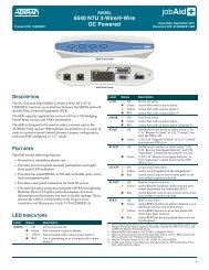
Shipping Contents<br />
The contents include the following items:<br />
• 4W <strong>ETO</strong><br />
• 4W <strong>ETO</strong> Installation and Maintenance Practice<br />
CAUTION<br />
Electronic modules can be damaged by ESD.<br />
When handling modules, wear an antistatic<br />
discharge wrist strap to prevent damage to<br />
electronic components. Place modules in<br />
antistatic packing material when transporting<br />
or storing. When working on modules, always<br />
place them on an approved antistatic mat that is<br />
electrically grounded.<br />
Instructions for Installing the <strong>Module</strong><br />
The 4W <strong>ETO</strong> inserts into any access module slot (1<br />
through 24) of a <strong>Total</strong> <strong>Access</strong> <strong>1500</strong> chassis. To install<br />
the 4W <strong>ETO</strong>, perform the following steps:<br />
1. If present, remove the <strong>Access</strong> <strong>Module</strong> Blank (P/N<br />
1175099L1) from the appropriate access module<br />
slot of the <strong>Total</strong> <strong>Access</strong> <strong>1500</strong> chassis.<br />
2. Hold the unit by the front panel while supporting<br />
the bottom side with the ejector latch, located on<br />
the lower left-hand side of the module, at the<br />
bottom and opened to engage the chassis edge<br />
when it is plugged in.<br />
3. Align the module edges to fit in the lower and<br />
upper guide grooves for the designated slot.<br />
4. Slide the module into the access module slot while<br />
pressing equally on the top and bottom of the front<br />
panel until the module is firmly positioned against<br />
the backplane of the chassis.<br />
5. Lock the module in place by pushing in on the<br />
ejector latch.<br />
The 4W <strong>ETO</strong> initializes and goes operational upon<br />
insertion into an active <strong>Total</strong> <strong>Access</strong> <strong>1500</strong> chassis.<br />
Initialization is indicated by the front panel LED.<br />
Front Panel LED<br />
The <strong>Total</strong> <strong>Access</strong> <strong>1500</strong> 4W <strong>ETO</strong> has one front panel<br />
LED that provides status information. See Table 3 for<br />
LED indications.<br />
Table 3. Front Panel LED<br />
Status Description<br />
Green Port is in normal operation<br />
Yellow Menu controlled test is in progress<br />
Red Port failure has been detected<br />
Red (Flashing) Hardware failure has been detected<br />
4 Issue 1, October 2003 61180113L2-5A