Total Access 1500 Single 4-Wire ETO Access Module ... - Adtran
Total Access 1500 Single 4-Wire ETO Access Module ... - Adtran
Total Access 1500 Single 4-Wire ETO Access Module ... - Adtran

You also want an ePaper? Increase the reach of your titles
YUMPU automatically turns print PDFs into web optimized ePapers that Google loves.
<strong>Total</strong> <strong>Access</strong> <strong>1500</strong> <strong>Single</strong> 4-<strong>Wire</strong> <strong>ETO</strong> <strong>Access</strong> <strong>Module</strong><br />
Installation and Maintenance Practice<br />
CONTENTS<br />
1. General ................................................................... 1<br />
2. Description ............................................................. 1<br />
3. Installation.............................................................. 4<br />
4. Provisioning ........................................................... 5<br />
5. Test Features .......................................................... 7<br />
6. Maintenance ........................................................... 7<br />
7. Specifications ......................................................... 7<br />
8. Warranty and Customer Service ............................ 7<br />
FIGURES<br />
Figure 1. <strong>Total</strong> <strong>Access</strong> <strong>1500</strong> 4W <strong>ETO</strong> ....................... 1<br />
Figure 2. 4W <strong>ETO</strong> Block Diagram ............................ 2<br />
Figure 3. 4W <strong>ETO</strong> Menu Tree ................................... 6<br />
TABLES<br />
Table 1. Time Slot and Wiring Interconnect ............ 3<br />
Table 2. Compliance Codes...................................... 4<br />
Table 3. Front Panel LED ......................................... 4<br />
Table 4. 4W <strong>ETO</strong> General Options .......................... 5<br />
Table 5. 4W <strong>ETO</strong> Equalizer Options........................ 5<br />
Table 6. 4W <strong>ETO</strong> Specifications .............................. 8<br />
1. GENERAL<br />
This practice is an installation and maintenance guide<br />
for the ADTRAN <strong>Total</strong> <strong>Access</strong> ® <strong>1500</strong> <strong>Single</strong> 4-<strong>Wire</strong><br />
Equalized Transmission Only (<strong>ETO</strong>) access module<br />
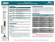
(P/N 1180113L2). Figure 1 is an illustration showing<br />
the front panel of the <strong>Single</strong> 4-<strong>Wire</strong> <strong>ETO</strong> (4W <strong>ETO</strong>).<br />
Revision History<br />
This is the initial issue of this practice. Future changes<br />
to this documentation will be explained in this<br />
subsection.<br />
2. DESCRIPTION<br />
The 4W <strong>ETO</strong> was designed for use in the <strong>Total</strong> <strong>Access</strong><br />
<strong>1500</strong> chassis. The 4W <strong>ETO</strong> provides two individual<br />
voice grade 4-wire analog interfaces between a Voice<br />
Frequency (VF) transmission facility and the <strong>Total</strong><br />
<strong>Access</strong> <strong>1500</strong> chassis backplane. No signaling is<br />
generated by the 4W <strong>ETO</strong>, but in-band signaling tones<br />
sent as part of the data stream will be transmitted by the<br />
circuit.<br />
Section 61180113L2-5A<br />
Issue 1, October 2003<br />
CLEI Code: VAL230KA_ _<br />
4W <strong>ETO</strong><br />
1180113L2<br />
Figure 1. <strong>Total</strong> <strong>Access</strong> <strong>1500</strong> 4W <strong>ETO</strong><br />
Features<br />
The basic features of the <strong>Total</strong> <strong>Access</strong> <strong>1500</strong> 4W <strong>ETO</strong>,<br />
(P/N 1180113L2) include the following:<br />
• A DC-isolated 4-wire VF channel interface.<br />
• Extended operating temperature range from –40ºC<br />
to +65ºC<br />
• TLP transmit input and receive output ranges that<br />
are adjustable in 0.1 dB increments.<br />
• Support for equalizer prescription settings as<br />
defined in AT&T 855-351-105 (309B).<br />
• Support for 150, 600 and 1200 ohms input/output<br />
termination impedance.<br />
• Support for loaded and nonloaded cable types.<br />
• Support for Sealing Current configurations for<br />
Sink, Source or None.<br />
• Provisioning via the SCU ADMIN port or remote<br />
craft interface.<br />
• Digital Loopback and 1004 Hz Digital Reference<br />
Signal (DRS) Tone Tests<br />
• NEBS Level 3 and UL 60950 compliant<br />
Trademarks: Any brand names and product names included in this document are<br />
61180113L2-5A trademarks, registered trademarks, or trade names of their respective holders.<br />
1<br />
STATUS
Time Slot Assignments<br />
For time slot assignments in the Dual T1 mode and in<br />
the Quad T1 mode, see Table 1.<br />
The <strong>Total</strong> <strong>Access</strong> <strong>1500</strong> platform can have multiple time<br />
slots in the T1 data stream assigned to each physical slot<br />
in the channel bank. The <strong>Total</strong> <strong>Access</strong> <strong>1500</strong> allows craft<br />
selectable time slots using the electronic provisioning<br />
interface. The system will automatically map DS0s in<br />
the T1 as determined by the LIU operational configuration<br />
or manual mapping is possible via the LIU<br />
configuration menu.<br />
Tx<br />
(In)<br />
T<br />
R<br />
TLP<br />
18.5 dBm to + 7.5 dBm<br />
Rx<br />
(Out)<br />
T1<br />
R1<br />
TLP<br />
18.5 dBm to + 7.5 dBm<br />
(150 and 600 ohms)<br />
or<br />
20.0 to + 5.5 dBm<br />
(1200 ohms)<br />
SP<br />
SP<br />
Sealing<br />
Current<br />
Detector<br />
Sealing<br />
Current<br />
Generator<br />
SP<br />
SP<br />
1:1<br />
(~20 mA DC)<br />
1:1<br />
SP<br />
48V<br />
48V Rtn.<br />
SP<br />
Circuit 1<br />
Termination<br />
Matching<br />
Circuit<br />
(150, 600 or 1200<br />
ohms)<br />
Gain<br />
Correction<br />
Circuit<br />
Gain<br />
Correction<br />
Circuit<br />
Termination<br />
Matching<br />
Circuit<br />
(150, 600 or 1200<br />
ohms)<br />
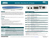
Figure 2. 4W <strong>ETO</strong> Block Diagram<br />
Connections<br />
Two of the four 50-pin male amphenol connectors (P1<br />
through P4) on the rear of the <strong>Total</strong> <strong>Access</strong> <strong>1500</strong><br />
chassis provide the interconnections to each of the 24<br />
physical <strong>Access</strong> <strong>Module</strong> slots on the chassis. The 4W<br />
<strong>ETO</strong> uses P1 (T/R) and P2 (T1/R1) for the port 1<br />
connections. See Table 1 for wiring interconnection<br />
details.<br />
<strong>ETO</strong> <strong>Access</strong> <strong>Module</strong> Block Diagram<br />
Figure 2 shows a functional block diagram of the 4W<br />
<strong>ETO</strong> <strong>Access</strong> <strong>Module</strong>.<br />
<strong>Total</strong> <strong>Access</strong> <strong>1500</strong><br />
<strong>Single</strong> 4-<strong>Wire</strong> <strong>ETO</strong><br />
<strong>Access</strong> <strong>Module</strong><br />
(P/N 1180113L2)<br />
2 Issue 1, October 2003 61180113L2-5A<br />
SP<br />
Symbols<br />
= Fuses<br />
= Surge protection devices<br />
Codec<br />
Voiceband<br />
Processor<br />
(Equalizer, Gains,<br />
Filters, etc.)<br />
Microcontroller<br />
1<br />
STATUS<br />
TDATA<br />
RDATA<br />
SPI IN<br />
SPI OUT<br />
Front<br />
Panel<br />
LED<br />
<strong>Total</strong> <strong>Access</strong><br />
<strong>1500</strong><br />
PCM Backplane<br />
}<br />
}<br />
Payload DS0<br />
0.0 dBm<br />
Target Level<br />
SPI Interface<br />
(Menu Traffic,<br />
System<br />
Commands)
Physical<br />
Slot<br />
Table 1. Time Slot and Wiring Interconnect<br />
Associated T1/DS0<br />
<strong>Single</strong> T1 Dual T1 Quad T1 (D4) Quad T1 (D1D)<br />
1 A1 A1 A1 A1 1<br />
2 A2 A3 A5 A9 1<br />
3 A3 A5 A9 A17 1<br />
4 A4 A7 A13 A2 1<br />
5 A5 A9 A17 A10 1<br />
6 A6 A11 A21 A18 1<br />
7 A7 A13 B1 B1 1<br />
8 A8 A15 B5 B9 1<br />
9 A9 A17 B9 B17 1<br />
10 A10 A19 B13 B2 1<br />
11 A11 A21 B17 B10 1<br />
12 A12 A23 B21 B18 1<br />
13 A13 B1 C1 C1 1<br />
14 A14 B3 C5 C9 1<br />
15 A15 B5 C9 C17 1<br />
16 A16 B7 C13 C2 1<br />
17 A17 B9 C17 C10 1<br />
18 A18 B11 C21 C18 1<br />
19 A19 B13 D1 D1 1<br />
20 A20 B15 D5 D9 1<br />
21 A21 B17 D9 D17 1<br />
22 A22 B19 D13 D2 1<br />
23 A23 B21 D17 D10 1<br />
24 A24 B23 D21 D18 1<br />
61180113L2-5A Issue 1, October 2003 3<br />
Port<br />
Amphenol<br />
Connection<br />
P1 – 26/1<br />
P2 – 26/1<br />
P1 – 27/2<br />
P2 – 27/2<br />
P1 – 28/3<br />
P2 – 28/3<br />
P1 – 29/4<br />
P2 – 29/4<br />
P1 – 30/5<br />
P2 – 30/5<br />
P1 – 31/6<br />
P2 – 31/6<br />
P1 – 32/7<br />
P2 – 32/7<br />
P1 – 33/8<br />
P2 – 33/8<br />
P1 – 34/9<br />
P2 – 34/9<br />
P1 – 35/10<br />
P2 – 35/10<br />
P1 – 36/11<br />
P2 – 36/11<br />
P1 – 37/12<br />
P2 – 37/12<br />
P1 – 38/13<br />
P2 – 38/13<br />
P1 – 39/14<br />
P2 – 39/14<br />
P1 – 40/15<br />
P2 – 40/15<br />
P1 – 41/16<br />
P2 – 41/16<br />
P1 – 42/17<br />
P2 – 42/17<br />
P1 – 43/18<br />
P2 – 43/18<br />
P1 – 44/19<br />
P2 – 44/19<br />
P1 – 45/20<br />
P2 – 45/20<br />
P1 – 46/21<br />
P2 – 46/21<br />
P1 – 47/22<br />
P2 – 47/22<br />
P1 – 48/23<br />
P2 – 48/23<br />
P1 – 49/24<br />
P2 – 49/24<br />
Interconnect<br />
Wiring<br />
T/R<br />
T1/R1<br />
T/R<br />
T1/R1<br />
T/R<br />
T1/R1<br />
T/R<br />
T1/R1<br />
T/R<br />
T1/R1<br />
T/R<br />
T1/R1<br />
T/R<br />
T1/R1<br />
T/R<br />
T1/R1<br />
T/R<br />
T1/R1<br />
T/R<br />
T1/R1<br />
T/R<br />
T1/R1<br />
T/R<br />
T1/R1<br />
T/R<br />
T1/R1<br />
T/R<br />
T1/R1<br />
T/R<br />
T1/R1<br />
T/R<br />
T1/R1<br />
T/R<br />
T1/R1<br />
T/R<br />
T1/R1<br />
T/R<br />
T1/R1<br />
T/R<br />
T1/R1<br />
T/R<br />
T1/R1<br />
T/R<br />
T1/R1<br />
T/R<br />
T1/R1<br />
T/R<br />
T1/R1
Compliance<br />
Table 2 shows the Compliance Codes for the 4W <strong>ETO</strong>.<br />
The 4W <strong>ETO</strong> is NRTL listed to the applicable UL<br />
standards. The 4W <strong>ETO</strong> is to be installed in a restricted<br />
access location and in a Type “B” or “E” enclosure<br />
only. The <strong>Total</strong> <strong>Access</strong> <strong>1500</strong> chassis Frame Ground<br />
terminal must be connected to an earth ground to ensure<br />
that the front panel of the 4W <strong>ETO</strong> is properly grounded<br />
via the backplane connector.<br />
This device complies with Part 15 of the FCC rules.<br />
Operation is subject to the following two conditions:<br />
1. This device may not cause harmful interference.<br />
2. This device must accept any interference received,<br />
including interference that may cause undesired<br />
operation.<br />
Changes or modifications not expressly approved by<br />
ADTRAN could void the user’s authority to operate this<br />
equipment.<br />
3. INSTALLATION<br />
Table 2. Compliance Codes<br />
Code Input Output<br />
Power Code (PC) F C<br />
Telecommunication Code (TC) – X<br />
Installation Code (IC) A –<br />
C A U T I O N !<br />
SUBJECT TO ELECTROSTATIC DAMAGE<br />
OR DECREASE IN RELIABILITY.<br />
HANDLING PRECAUTIONS REQUIRED.<br />
After unpacking the <strong>Total</strong> <strong>Access</strong> <strong>1500</strong> 4W <strong>ETO</strong>,<br />
inspect it for damage. If damage has occurred, file a<br />
claim with the carrier, then contact ADTRAN Customer<br />
Service. Refer to the Warranty and Customer Service<br />
section for further information. If possible, keep the<br />
original shipping container for returning the 4W <strong>ETO</strong><br />
for repair or for verification of shipping damage.<br />
Shipping Contents<br />
The contents include the following items:<br />
• 4W <strong>ETO</strong><br />
• 4W <strong>ETO</strong> Installation and Maintenance Practice<br />
CAUTION<br />
Electronic modules can be damaged by ESD.<br />
When handling modules, wear an antistatic<br />
discharge wrist strap to prevent damage to<br />
electronic components. Place modules in<br />
antistatic packing material when transporting<br />
or storing. When working on modules, always<br />
place them on an approved antistatic mat that is<br />
electrically grounded.<br />
Instructions for Installing the <strong>Module</strong><br />
The 4W <strong>ETO</strong> inserts into any access module slot (1<br />
through 24) of a <strong>Total</strong> <strong>Access</strong> <strong>1500</strong> chassis. To install<br />
the 4W <strong>ETO</strong>, perform the following steps:<br />
1. If present, remove the <strong>Access</strong> <strong>Module</strong> Blank (P/N<br />
1175099L1) from the appropriate access module<br />
slot of the <strong>Total</strong> <strong>Access</strong> <strong>1500</strong> chassis.<br />
2. Hold the unit by the front panel while supporting<br />
the bottom side with the ejector latch, located on<br />
the lower left-hand side of the module, at the<br />
bottom and opened to engage the chassis edge<br />
when it is plugged in.<br />
3. Align the module edges to fit in the lower and<br />
upper guide grooves for the designated slot.<br />
4. Slide the module into the access module slot while<br />
pressing equally on the top and bottom of the front<br />
panel until the module is firmly positioned against<br />
the backplane of the chassis.<br />
5. Lock the module in place by pushing in on the<br />
ejector latch.<br />
The 4W <strong>ETO</strong> initializes and goes operational upon<br />
insertion into an active <strong>Total</strong> <strong>Access</strong> <strong>1500</strong> chassis.<br />
Initialization is indicated by the front panel LED.<br />
Front Panel LED<br />
The <strong>Total</strong> <strong>Access</strong> <strong>1500</strong> 4W <strong>ETO</strong> has one front panel<br />
LED that provides status information. See Table 3 for<br />
LED indications.<br />
Table 3. Front Panel LED<br />
Status Description<br />
Green Port is in normal operation<br />
Yellow Menu controlled test is in progress<br />
Red Port failure has been detected<br />
Red (Flashing) Hardware failure has been detected<br />
4 Issue 1, October 2003 61180113L2-5A
4. PROVISIONING<br />
There are no hardware options in the 4W <strong>ETO</strong> access<br />
module; its specific options can be provisioned from the<br />
SCU ADMIN port or remote craft interface. The factory<br />
default settings for the 4W <strong>ETO</strong> access module are<br />
noted in bold text in Table 4 and Table 5.<br />
Table 4. 4W <strong>ETO</strong> General Options<br />
Function Option Description<br />
Transmit TLP –18.0 to +7.5 dBm (+0.0) Sets the transmit channel attenuation in 0.1 dBm increments<br />
from the customer to the network.<br />
Receive TLP:<br />
150 and 600 ohms<br />
1200 ohms<br />
Sealing Current Mode None<br />
Sink<br />
Source<br />
Tx Termination (1) 150 ohms<br />
600 ohms<br />
1200 ohms<br />
Rx Termination (1) 150 ohms<br />
600 ohms<br />
1200 ohms<br />
Equalizer Options Height<br />
Bandwidth<br />
Slope<br />
Cable Type<br />
–18.0 to +7.5 dBm (+0.0)<br />
–20.0 to +5.5 dBm (+0.0)<br />
Sets the receive channel attenuation, in 0.1 dBm increments<br />
from the network to the customer.<br />
Sets the sealing current mode of operation.<br />
Selects the impedance of the Transmit T/R pair from the<br />
customer toward the T1 network.<br />
Selects the impedance of the T1/R1 pair toward the customer.<br />
See Table 5 for detailed descriptions of the equalizer<br />
provisioning options.<br />
Note: Defaults are in bold type.<br />
(1) Although no restrictions are placed on the termination settings relative to the equalizer settings, the following configurations<br />
are typical: 600 ohms and 1200 ohms impedances can be used in conjunction with active equalization.<br />
The 150 ohms and 600 ohms impedances can be used with mismatched equalization. The 600 ohms impedance can<br />
also be used on short nonloaded loops where no equalization is necessary.<br />
Table 5. 4W <strong>ETO</strong> Equalizer Options<br />
Function Option Description<br />
Height 0 to 15 In conjunction with Bandwidth Equalization, corrects for<br />
frequency response degradation at the high end of the voice<br />
range due to cable length by increasing the 3250-Hz equalization<br />
bump.<br />
Bandwidth 0 to 15 In conjunction with Height Equalization, corrects for frequency<br />
response degradation at the high end of the voice range due to<br />
cable length by increasing the breadth of the equalization bump.<br />
Slope 0 to 15 Corrects for frequency response degradation at the low end of<br />
the voice range due to cable length.<br />
Cable Type Non-Loaded<br />
Loaded<br />
Used to specify loaded or nonloaded cable. This option modifies<br />
the equalization circuitry to provide greater gain at the higher<br />
frequencies when transmitting over nonloaded cable.<br />
61180113L2-5A Issue 1, October 2003 5
Windows HyperTerminal<br />
Windows HyperTerminal can be used as a VT100<br />
terminal emulation program. Open HyperTerminal by<br />
selecting Programs/<strong>Access</strong>ories/HyperTerminal. Refer<br />
to the Help section of HyperTerminal for additional<br />
information.<br />
NOTE<br />
To ensure proper display background, select<br />
VT100 terminal emulation under SETTINGS.<br />
Password and User Name<br />
Password protection is a function of the SCU and is<br />
factory disabled. If password authentication is enabled,<br />
then the SCU will display the Logon screen. A valid<br />
User Name and Password are required to access the<br />
menus.<br />
1. Configuration<br />
2. Provisioning<br />
3. Status<br />
4. Test<br />
Unit Name<br />
CLEI Code<br />
Part Number<br />
Software Revision<br />
FPGA Revision<br />
1. Transmit TLP<br />
2. Receive TLP<br />
3. Tx Termination<br />
4. Rx Termination<br />
5. Sealing Current Mode<br />
6. Equalizer Options<br />
Transmit TLP<br />
Receive TLP<br />
Sealing Cur Mode<br />
Sealing Cur State<br />
EQ Height<br />
EQ Bandwidth<br />
EQ Slope<br />
Cable Type<br />
Digital Test<br />
Metallic Test<br />
1. 1004Hz Tone Test<br />
2. Digital Network Loopback<br />
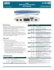
Figure 3. 4W <strong>ETO</strong> Menu Tree<br />
NOTE<br />
The default User Name is “user”, and the<br />
default Password is “password”. The User<br />
Name and Password are not case sensitive.<br />
Menu Navigation<br />
To traverse through the menus, select the desired entry<br />
and press ENTER. To work backward in the menu, press<br />
the ESC key.<br />
The menu tree in Figure 3 illustrates the path to every<br />
provisioning, performance, and test access point in the<br />
4W <strong>ETO</strong> menu.<br />
Enter Value<br />
1. 150<br />
2. 600<br />
3. 1200<br />
1. None<br />
2. Sink<br />
3. Source<br />
1. Off<br />
2. To Network<br />
3. To Loop<br />
4. To Loop and Network<br />
1. Inactive<br />
2. Active<br />
6 Issue 1, October 2003 61180113L2-5A<br />
1. 150<br />
2. 600<br />
3. 1200<br />
1. Height<br />
2. Bandwidth<br />
3. Slope<br />
4. Cable Type<br />
Enter Value<br />
1. Loaded<br />
2. Unloaded
5. TEST FEATURES<br />
The 4-<strong>Wire</strong> <strong>ETO</strong> supports a Digital Network Loopback<br />
and 1004 Hz Tone Tests to support circuit turn-up and<br />
maintenance efforts. Test functions can be activated<br />
locally via the ADMIN port on the SCU or remotely via<br />
Telnet or SNMP.<br />
NOTE<br />
The tests cannot run simultaneously. If a test is<br />
in progress and another test is initiated, the first<br />
test will be terminated when the new test starts.<br />
Digital Network Loopback Test<br />
The Digital Network Loopback test activates a<br />
loopback path that takes the DS0 data received from the<br />
network and transmits it back to the network in the<br />
appropriate port's transmit time slot.<br />
1004 Hz Tone Test<br />
The 1004 Hz Tone Test generates a 1004 Hz @ 0 dBm<br />
Digital Reference Signal (DRS) tone, which is used to<br />
send DRS signal to the loop, the network, or to both<br />
simultaneously.<br />
6. MAINTENANCE<br />
The <strong>Total</strong> <strong>Access</strong> <strong>1500</strong> 4W <strong>ETO</strong> requires no routine<br />
maintenance for normal operation.<br />
ADTRAN does not recommend that repairs be<br />
attempted in the field. Repair services may be obtained<br />
by returning the defective unit to ADTRAN. Refer to<br />
the Warranty and Customer Service section for further<br />
information.<br />
7. SPECIFICATIONS<br />
Specifications for the <strong>Total</strong> <strong>Access</strong> <strong>1500</strong> 4W <strong>ETO</strong> are<br />
detailed in Table 6.<br />
8. WARRANTY AND CUSTOMER SERVICE<br />
ADTRAN will replace or repair this product within the<br />
warranty period if it does not meet its published specifications<br />
or fails while in service. Warranty information<br />
can be found at www.adtran.com/warranty.<br />
U.S. and Canada customers can also receive a copy of<br />
the warranty via ADTRAN’s toll-free faxback server at<br />
877-457-5007.<br />
• Request Document 414 for the U.S. and Canada<br />
Carrier Networks Equipment Warranty.<br />
• Request Document 901 for the U.S. and Canada<br />
Enterprise Networks Equipment Warranty.<br />
Refer to the following subsections for sales, support,<br />
CAPS requests, or further information.<br />
ADTRAN Sales<br />
Pricing/Availability:<br />
800-827-0807<br />
ADTRAN Technical Support<br />
Pre-Sales Applications/Post-Sales Technical<br />
Assistance:<br />
800-726-8663<br />
Standard hours: Monday - Friday, 7 a.m. - 7 p.m. CST<br />
Emergency hours: 7 days/week, 24 hours/day<br />
ADTRAN Repair/CAPS<br />
Return for Repair/Upgrade:<br />
(256) 963-8722<br />
Repair and Return Address<br />
Contact Customer and Product Service (CAPS) prior to<br />
returning equipment to ADTRAN.<br />
ADTRAN, Inc.<br />
CAPS Department<br />
901 Explorer Boulevard<br />
Huntsville, Alabama 35806-2807<br />
61180113L2-5A Issue 1, October 2003 7
Table 6. 4W <strong>ETO</strong> Specifications<br />
Performance<br />
Transmit TLP (150, 600, or 1200 ohms): +7.5 to –18.0 dBm in 0.1 dB increments<br />
Receive TLP (150 and 600 ohms):<br />
Receive TLP (1200 ohms):<br />
+7.5 to –18.0 dBm in 0.1 dB increments<br />
+5.5 to –20.0 dBm in 0.1 dB increments<br />
Equalization (Transmit Channel): 309B Compatible Equalizer<br />
Frequency Response: ± 0.25 dB, 300 to 3000 Hz<br />
Echo Return Loss: ≥<br />
Singing Return Loss: ≥<br />
Longitudinal Balance: ≥<br />
≥<br />
Idle Channel Noise: ≤<br />
PCM Encoding/Decoding: µ-law<br />
Power<br />
Current Draw: 0.020 A maximum @ –48 V<br />
Physical<br />
Dimensions: 3.125 in. H x 0.62 in. W x 10.1 in. D<br />
Weight: < 1 lb.<br />
Operating Temperature:<br />
Storage Temperature:<br />
Environmental<br />
–40ºC to +70ºC<br />
–40ºC to +85ºC<br />
Relative Humidity: 95% maximum @ 50ºC noncondensing.<br />
Heat Dissipation: 1.2 watts maximum<br />
Compliance<br />
UL 1950<br />
NEBS Level 3<br />
FCC 47CFR Part 15, Class A<br />
Part Number<br />
<strong>Total</strong> <strong>Access</strong> <strong>1500</strong> 4-<strong>Wire</strong> Equalized Transmission Only<br />
(<strong>ETO</strong>) <strong>Access</strong> <strong>Module</strong>: 1180113L2<br />
8 Issue 1, October 2003 61180113L2-5A