

The New STFI-Former
The New STFI-Former
The New STFI-Former

Create successful ePaper yourself
Turn your PDF publications into a flip-book with our unique Google optimized e-Paper software.
<strong>The</strong> <strong>New</strong> <strong>STFI</strong>-<strong>Former</strong><br />
Bo Norman, Lennart Hermansson and Daniel Söderberg<br />
<strong>STFI</strong>-Packforsk, Stockholm, Sweden<br />
ABSTRACT<br />
In high-speed twin-wire roll-blade formers, a suction<br />
pulse is generated at wire exit from the forming roll<br />
(table roll suction effect), which may locally deflect the<br />
inner wire. This can generate large- and small-scale formation<br />
defects. Such defects have also been observed in<br />
high-speed hybrid roll-blade formers.<br />
By insertion of a machine wide blade with a thin,<br />
water meniscus breaking front edge, between inner wire<br />
and roll surface at roll exit, the suction pulse, and thus<br />
also the formation defects, can be avoided. This blade is<br />
named the <strong>STFI</strong>–Blade.<br />
<strong>The</strong> flow stability in the suspension between the wires<br />
at exit from the forming roll is very important, to avoid<br />
formation defects. This sometimes requires an improved<br />
headbox jet quality in comparison with industrial<br />
standards. <strong>The</strong> jet quality can be improved by a headbox<br />
nozzle with higher than traditional contraction ratio.<br />
<strong>The</strong> original twin-wire roll-blade <strong>STFI</strong>–<strong>Former</strong> has<br />
been modified to the <strong>New</strong> <strong>STFI</strong>–<strong>Former</strong> by the introduction<br />
of an <strong>STFI</strong>–Blade and the application of a headbox<br />
with high nozzle contraction. In this way, formation damages<br />
can be avoided even at high speeds.<br />
INTRODUCTION<br />
<strong>New</strong> high speed paper machines aimed at producing<br />
different kinds of printing paper qualities based on<br />
mechanical pulp or entirely on chemical pulp, are all<br />
relying on the twin-wire roll-blade forming principle. In<br />
such industrial machines, the current designs don’t seem<br />
to be principally stable, in the sense that different<br />
running parameters can be changed, without creating any<br />
formation problems. Typically, jet landing in the twinwire<br />
nip has to be on the outer wire, or formation<br />
damages will inevitably occur.<br />
One paper mill comment is: “To run our forming unit<br />
is like balancing on a knife edge”. Any change in pulp<br />
quality, grammage level, speed, slice opening etc may<br />
result in formation defects.<br />
At the 2007 PAPTAC Annual Meeting in Montreal,<br />
hybrid roll-blade forming was discussed [1], that is<br />
fourdrinier dewatering followed by a top wire unit<br />
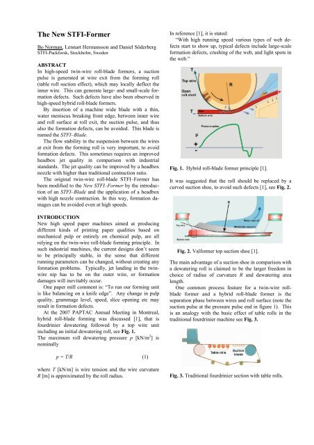
including an initial dewatering roll, see Fig. 1.<br />
<strong>The</strong> maximum roll dewatering pressure p [kN/m 2 ] is<br />
nominally<br />
p = T/R (1)<br />
where T [kN/m] is wire tension and the wire curvature<br />
R [m] is approximated by the roll radius.<br />
In reference [1], it is stated:<br />
“With high running speed various types of web defects<br />
start to show up, typical defects include large-scale<br />
formation defects, crushing of the web, and light spots in<br />
the web.”<br />
Fig. 1. Hybrid roll-blade former principle [1].<br />
It was suggested that the roll should be replaced by a<br />
curved suction shoe, to avoid such defects [1], see Fig. 2.<br />
Fig. 2. Valformer top suction shoe [1].<br />
<strong>The</strong> main advantage of a suction shoe in comparison with<br />
a dewatering roll is claimed to be the larger freedom in<br />
choice of radius of curvature R and dewatering area<br />
length.<br />
One common process feature for a twin-wire rollblade<br />
former and a hybrid roll-blade former is the<br />
separation phase between wires and roll surface (note the<br />
suction pulse at the pressure pulse end in figure 1). This<br />
is an analogy with the basic effect of table rolls in the<br />
traditional fourdrinier machine see Fig. 3.<br />
Fig. 3. Traditional fourdrinier section with table rolls.
Table rolls were applied already on the first paper<br />
machine in the 1820s, but the task was then only to keep<br />
the wire horizontal along the wire section in a frictionless<br />
way, while gravity generated dewatering.<br />
A suction pressure zone is generated in the downstream<br />
expansion zone between wire and roll. This<br />
causes a local downward deflection of the wire, which is<br />
followed by a corresponding upward movement to the<br />
next table roll. <strong>The</strong> vertical motions of the wire generate<br />
instabilities in the fibre suspension on the wire, “activity”,<br />
which may improve fibre deflocculation in the mix<br />
on the wire, and thus improve final web formation.<br />
During the 1950s, the table roll suction effect became<br />
stronger at increased machine speeds, and generated formation<br />
disturbances by excessive activity,. Wrist [2]<br />
studied the mechanisms, and showed that the suction<br />
pulse amplitude increases with the square of the machine<br />
speed.<br />
<strong>The</strong> solution to this problem was the introduction of<br />
the foil blade. This was a stationary, mainly flat element<br />
mounted below the wire, with a small angle against the<br />
wire. It was then possible, at every stage along the wire<br />
section, to choose a suitable angle to optimise activity in<br />
the suspension on the wire.<br />
<strong>The</strong> difference between table roll and foil blade pulse<br />
amplitudes is demonstrated in Fig. 4.<br />
Fig. 4. Suction pulses generated by a table roll (top)<br />
and a foil blade (bottom), [2].<br />
We now suggest that the change from twin-wire roll to<br />
suction shoe dewatering according to the Valformer<br />
concept is in analogy with the change from table roll to<br />
foil blade on the fourdrinier wire. <strong>The</strong> main advantage<br />
would then be to avoid the suction pulse after the<br />
forming roll.<br />
Based on the present study, it is suggested that suction<br />
pulse problems in high-speed roll-blade dewatering can<br />
be avoided with an alternative, less expensive design.<br />
This new design will be discussed in some detail below.<br />
ROLL / LOADABLE-BLADES FORMING<br />
Based on traditional roll forming technology [3], com–<br />
bined with Dörries loadable blades concept, [4], the first<br />
twin-wire roll/loadable-blades former, the <strong>STFI</strong><strong>Former</strong><br />
[5] was designed, and started up in June 1992, see Fig. 5.<br />
Fig. 5. <strong>The</strong> twin-wire roll-blade <strong>STFI</strong>-<strong>Former</strong> [5].<br />
<strong>The</strong> main idea behind this design was to make 3-ply<br />
forming possible. <strong>The</strong> outer layers should initially be<br />
dewatered over the forming roll. After this, the blade<br />
pulses should break down fibre flocs remaining at the<br />
centre, but mixing between the layers should be avoided,<br />
since the outer layers were already formed. An im–<br />
portant part of the design was that dewatering at each<br />
stage should be symmetrical. It was soon realised that<br />
the design would also be well suited for producing all<br />
types of single-layered printing papers.<br />
This basic roll/loadable-blades principle was later<br />
adopted by Voith as the Duoformer CFD, the TQv and<br />
the TQb designs, see Fig. 6.<br />
Fig. 6. <strong>The</strong> Voith twin-wire roll-blade former TQb<br />
(right), specifically designed for rebuilds of<br />
twin-wire roll formers (left).
<strong>The</strong> corresponding Valmet/Metso machines are Speedformer<br />
MB and Optiformer, see Fig. 7.<br />
Fig. 7. Valmet/Metso twin-wire roll-blade Optiformer.<br />
SUCTION PULSE EFFECTS<br />
<strong>The</strong> formation produced with the <strong>STFI</strong>-<strong>Former</strong> never<br />
reached the high levels expected. Different kinds of<br />
defects appeared in the products. One defect was a faint<br />
pattern similar to that of the forming roll shell surface.<br />
This was of the original KMW design, where wavy<br />
plates formed the space for dewatering to the roll side,<br />
see Fig. 8. It was suspected that fluid filled the areas<br />
below the “wave maxima”, and therefore locally accentuated<br />
the table roll suction effect, compared to the<br />
surrounding, not completely water filled areas.<br />
Fig. 8. Wavy plates at the KMW forming roll surface.<br />
Circles indicate holes connecting to suction chamber, [5].<br />
An agreement was made with Valmet, to manufacture a<br />
forming roll of the new design, based on conical holes,<br />
replacing the wavy plates, see Fig. 9.<br />
With the new forming roll, the web pattern from the<br />
wavy plates disappeared. However, some formation defects<br />
would still appear. It was therefore suggested that<br />
table roll suction effects still caused some problems.<br />
<strong>The</strong> dewatering pressure event along the FEX forming<br />
roll was measured, during such running conditions that<br />
left some free suspension between the wires at the end of<br />
roll dewatering, see Fig. 10.<br />
Fig. 9. Conical hole pattern in the new FEX forming roll<br />
from Valmet, [5].<br />
Fig. 10. Pressure event along the FEX forming roll. Roll<br />
diameter 1635 mm, wire wrapping angle 30 degrees,<br />
wire tension 7 kN/m, machine speed 800 m/min.<br />
FEX measurements in co-operation with Valmet, [6].<br />
A pressure sensor at the end of a thin flexible cord was<br />
released into the jet (A), then into the twin-wire roll zone<br />
(B), and finally into the zone where the wires leave the<br />
roll (C). It is evident that some pressure oscillation<br />
occurs around the end of roll dewatering. Such oscillations<br />
have been found by many investigators. It<br />
should be pointed out that in pure roll dewatering (where<br />
such oscillations do not occur), the outer wire rests on a<br />
solid web when leaving the forming roll, while in rollblade<br />
dewatering the wire then still floats on some free<br />
suspension.<br />
At the separation of the wires from the forming roll,<br />
local vacuum is generated by the table roll suction effect.<br />
We assumed that this suction pulse was a source for the<br />
upstream pressure fluctuations. Holm et.al. [7] therefore<br />
studied the pressure event and wire geometry in a model<br />
roll former with a solid roll for one-sided drainage. A<br />
spring-loaded, wire touching displacement sensor was<br />
mounted at the roll surface, by which it was possible to<br />
follow the wire position along the forming zone, see Fig.<br />
11.
Fig. 11. Left: Wire position transducer (bottom) and<br />
pressure probe (top). Right: Wire-to-roll distance along<br />
roll surface. Wire leaves the roll surface the minimum<br />
point to the right. In this example an impermeable wire<br />
was used, wire tension 5.5 kN/m, [7].<br />
It was demonstrated that the vacuum pulse generated<br />
when the wire left the forming roll also triggered the<br />
oscillations in wire curvature and pressure upstream, a<br />
phenomenon which could also explain the pressure<br />
pulsations noted in full scale operation (Fig. 10). Wire<br />
tension is here an important parameter.<br />
A suction pulse at roll exit means that the inner wire<br />
may be locally sucked away from the outer wire, when<br />
leaving the forming roll, see Fig. 12.<br />
Fig. 12. Local separation between inner and outer wires<br />
when leaving a forming roll.<br />
<strong>The</strong> local wire separation demonstrated in Fig. 12 may<br />
generate streaks and/or formation disturbances in the wet<br />
web on the outer wire. Like in the case of table rolls, the<br />
amplitude of the suction pulse increases with the square<br />
of the machine speed. This phenomenon is therefore of<br />
increasing importance in modern machines with<br />
successively higher running speeds.<br />
<strong>The</strong> first support blade against the inner wire is<br />
normally placed a minimum of 200 mm from the separation<br />
line from the roll. Due to the traditional size of<br />
support blade and mounting frame, it is difficult to<br />
reduce this distance significantly. This is the background<br />
for the insertion of a new blade. <strong>The</strong> main task for this<br />
new blade is to break the water meniscus between roll<br />
surface and inner wire at a very early stage, thus preventing<br />
the generation of a local vacuum pulse. <strong>The</strong>re<br />
will then be no local inner wire local deformation. To<br />
come close enough to the separation line between inner<br />
wire and roll surface, which is necessary to avoid a<br />
vacuum pulse, the blade front edge must be very thin.<br />
<strong>The</strong> new blade has one flat surface, to face the inner<br />
wire, and one curved surface (with forming roll radius) to<br />
face the forming roll surface <strong>The</strong> blade edge may be<br />
tapered. This new blade is named the <strong>STFI</strong>-Blade [8].<br />
Eq. 2. describes the relationship between the free wire<br />
length L [mm] from the separation line on a forming roll<br />
with diameter D [mm] to the front edge of an <strong>STFI</strong>-Blade<br />
with front edge thickness d [mm], when the blade is<br />
mounted to just touch both inner wire and roll surface.<br />
L = √d x D (2)<br />
To test the concept, an <strong>STFI</strong>-Blade of glass fibre reinforced<br />
polymer was manufactured, with a front edge<br />
thickness of ca 0.5 mm, see Fig. 13.<br />
Fig. 13. <strong>The</strong> <strong>STFI</strong>-Blade , mounted at the wire exit from<br />
the forming roll in the <strong>STFI</strong>-<strong>Former</strong> [8].<br />
It should be pointed out that, contrary to the traditional<br />
deflector blades in a roll-blade former, the <strong>STFI</strong>-Blade<br />
does not generate any wire deflection. <strong>The</strong>refore, no<br />
normal forces act on the blade surfaces, which then<br />
means a low level of frictional forces along the blade<br />
surfaces. <strong>The</strong> insertion of the <strong>STFI</strong>-Blade gave a free<br />
wire length of ca 30 mm. <strong>The</strong> original <strong>STFI</strong>-Blade was<br />
mounted in the <strong>STFI</strong>-<strong>Former</strong> in 2004 and still (in 2007)<br />
does not show significant wear.<br />
Streaks and large scale formation defects, at times<br />
present in the paper produced with the <strong>STFI</strong>-<strong>Former</strong>,<br />
were avoided after the introduction of the <strong>STFI</strong>-Blade.<br />
However, a large number of small scale light spots<br />
unexpectedly appeared in the web, see Fig. 14.
Fig. 14. Light spots appearing in the paper web at the<br />
introduction of the <strong>STFI</strong>-Blade.<br />
Fine paper, 60 g/m 2 , 800 m/min.<br />
FLOW STABILITY AT ROLL EXIT<br />
It was – at length – concluded that the formation defects<br />
generated by the <strong>STFI</strong>-Blade could possibly be caused by<br />
flow instabilities in the free suspension between the webs<br />
leaving the roll dewatering section.<br />
It was already in 1982 demonstrated on the FEX<br />
machine that a twin-wire blade former is much more<br />
sensitive than a twin-wire roll former regarding jet velocity<br />
fluctuations. <strong>The</strong> original headbox on the FEX<br />
machine was a KMW headbox of high turbulence level<br />
design, initially developed for the application in twinwire<br />
roll forming only.<br />
Fig. 15. KMW-HTB (High Turbulence headBox) from<br />
the 1970s.<br />
At the start-up of the FEX machine, this headbox was<br />
applied in the twin-wire roll former as well as in the<br />
twin-wire blade former. <strong>The</strong> types of formation obtained<br />
are demonstrated in Fig. 16.<br />
Replacement of the KMW-HTB headbox by a Beloit<br />
Converflo headbox (with a very high nozzle contraction<br />
ratio) in the FEX blade former, produced an excellent<br />
paper formation. This clearly demonstrated that in twinwire<br />
blade forming, the level of flow instabilities in the<br />
headbox jet – which is lower, the higher the nozzle contraction<br />
ratio – has to be very low.<br />
Fig. 16. Twin-wire forming on the FEX machine with<br />
unbleached kraft pulp, using the KMW-HTB headbox.<br />
Left: Sample from roll forming, Right: Sample from<br />
blade forming.<br />
When initial roll dewatering, followed by blade dewatering<br />
originally was chosen as the concept for the <strong>STFI</strong>-<br />
<strong>Former</strong>, [5], it was based on this knowledge, that roll<br />
forming is much less sensitive than blade forming to<br />
headbox jet instabilities. Since the major part of dewatering<br />
in a roll-blade former takes place already over the<br />
forming roll, it had earlier never been suspected that<br />
instabilities in the suspension leaving the roll could be a<br />
problem.<br />
Only when the web damages according to Fig. 14<br />
appeared, suspicions about the quality of the headbox jet<br />
came up. In the original tests of the <strong>STFI</strong>-Blade in the<br />
<strong>STFI</strong>-<strong>Former</strong>, a traditional hydraulic headbox with a<br />
nozzle contraction ratio of ca 10 (designed in cooperation<br />
between <strong>STFI</strong> and Valmet and manufactured<br />
by Valmet) was used, see Fig. 17.<br />
Fig. 17. <strong>STFI</strong>/Valmet headbox with traditional (low)<br />
nozzle contraction ratio.<br />
<strong>The</strong> <strong>STFI</strong>/Valmet headbox was replaced by a headbox<br />
with a nozzle contraction ratio of ca 25 (designed by<br />
<strong>STFI</strong> and manufactured by Uddevalla Mekaniska Verkstad).<br />
<strong>The</strong> first test run with this headbox and with the<br />
<strong>STFI</strong>-Blade in the <strong>STFI</strong>-<strong>Former</strong> was made on September<br />
6, 2004.
Fig. 18. <strong>STFI</strong>/UMV headbox with high nozzle contraction<br />
ratio.<br />
It was then found, that the light spot defects which had<br />
been generated at the original tests of the <strong>STFI</strong>-Blade,<br />
disappeared when a high-contraction headbox nozzle was<br />
used.<br />
In comparison with the traditional <strong>STFI</strong>-<strong>Former</strong>, the<br />
<strong>New</strong> <strong>STFI</strong>-<strong>Former</strong> therefore specifies:<br />
• An <strong>STFI</strong>-Blade mounted at wire exit from the<br />
forming roll, [8].<br />
• A headbox with significantly higher nozzle<br />
contraction ratio than traditional, [9].<br />
CONCLUSIONS<br />
In twin-wire roll-blade formers, a local suction pulse is<br />
created when the wires leave the forming roll. This<br />
suction pulse may locally deform the path of the inner<br />
wire, and then create various kinds of formation defects.<br />
<strong>The</strong> effect of the suction pulse will increase with the<br />
square of the machine speed, which means that the<br />
problems will accelerate with the increasing speeds of<br />
modern machines.<br />
<strong>The</strong> local suction pulse can be avoided, if the water<br />
meniscus between inner wire and roll surface is broken<br />
by a machine wide, thin blade edge, close to the exit line<br />
from the forming roll. <strong>The</strong> related web formation defects<br />
can then be avoided.<br />
<strong>The</strong> insertion of such a blade is also an alternative to<br />
replacing the forming roll by a vacuum shoe in hybrid<br />
roll-blade forming [1].<br />
Flow instabilities in the suspension between the webs<br />
when leaving the forming roll may also generate<br />
formation defects. Such instabilities can be reduced, if<br />
the headbox nozzle contraction ratio is sufficiently high –<br />
which may require a higher than traditional ratio. In<br />
hybrid roll-blade forming, the level of activity in the<br />
suspension on the fourdrinier wire in front of the twinwire<br />
roll nip should be limited.<br />
REFERENCES<br />
1. Swietlik, F., Partanen, H., Puurtinen, A., Turunen, R.; <strong>New</strong><br />
former technology to improve sheet quality and printability.<br />
In: PAPTAC 93rd Annual Meeting 2007. Proceedings A,<br />
139-142.<br />
2. Wrist, P.: Dynamics of sheet formation on the fourdrinier<br />
machine. In: <strong>The</strong> formation and structure of paper.<br />
Transactions of the 2nd Fundamental Research Symposium<br />
held at Oxford, 1961. Vol 2, 839-888.<br />
3. Webster, D., Continuous web forming machine, Patent U.S.<br />
3 056 719 (2 October 1962, filed 9 July 1959).<br />
4. Banning, J., Vorrichtung zum Führen der Siebe einer<br />
Doppelsiebpartie einer Papier- oder Kartonmaschine, Dörries,<br />
Germany, Patent DE 35 03 242 ( 7 August 1986, filed<br />
31 January 1985).<br />
5. Nordström, B., Norman, B. Development of the <strong>STFI</strong>-For–<br />
mer. Nordic Pulp Paper Res. J. 9(1994): 3, 176-181.<br />
6. Martinez, M, Characterizing the dewatering rate in roll gap<br />
formers. J. Pulp Paper Sci. 24(1998):1, 7-13<br />
7. Holm, R., Söderberg, D., Norman, B. Experimental studies<br />
on dewatering during roll forming of paper. Nordic Pulp<br />
Paper Res. J., 20(2005):2, 205-211.<br />
8. Hermansson, L., Norman, B., Dewatering apparatus. <strong>STFI</strong>-<br />
Packforsk, Sweden. Patent application SE 0500447-8, (28<br />
February 2005)<br />
9. Norman, B., Hermansson, L., Söderberg., Dewatering arrangement<br />
adopted to use in a twin-wire dewatering section<br />
of a stock processing machine. <strong>STFI</strong>-Packforsk, Sweden,<br />
Patent SE 526969. (29 November 2005, filed 28 February<br />
2005).


