Leigh Multiple Morise and Tenon Attachment User Guide - Leigh Jigs
Leigh Multiple Morise and Tenon Attachment User Guide - Leigh Jigs
Leigh Multiple Morise and Tenon Attachment User Guide - Leigh Jigs

You also want an ePaper? Increase the reach of your titles
YUMPU automatically turns print PDFs into web optimized ePapers that Google loves.
LEIGH USER GUIDE<br />
<strong>Multiple</strong> Mortise<br />
<strong>and</strong> <strong>Tenon</strong> <strong>Attachment</strong><br />
Joining Tradition with Today
ii<br />
Your New <strong>Leigh</strong> M2 <strong>Attachment</strong><br />
Congratulations! You now own the world’s<br />
only jig for routing multiple mortise <strong>and</strong> tenon<br />
joints; one of the most difficult joints to h<strong>and</strong>cut<br />
is made simple with the M2.<br />
The M2 is an optional attachment for the <strong>Leigh</strong><br />
Dovetail <strong>Jigs</strong>: 24" [610mm] models D1258,<br />
D1258R, D3, D4 <strong>and</strong> D4R. Most illustrations<br />
in this guide show the M2 mounted on the<br />
D4 jig but the instructions are identical for<br />
all the D4R <strong>and</strong> all earlier D series jigs.<br />
Important: Inches <strong>and</strong> Millimetres<br />
<strong>Leigh</strong> makes the M2 attachment in two models;<br />
inch or metric. Text <strong>and</strong> illustrations in this<br />
<strong>Leigh</strong> English-language user guide indicate<br />
dimensions in both inches <strong>and</strong> millimetres.<br />
Dimensions are indicated in text <strong>and</strong> illustrations<br />
with inches first, followed by millimetres<br />
in square brackets.<br />
Example: 3 ⁄4" x 5 1 ⁄2" x 8" [20 x 140 x 200mm]<br />
Do not be concerned if the inch/millimetre<br />
equivalents are not always exact. Just use the<br />
dimensions which apply to your jig.<br />
Where finger assembly or template scales<br />
overlay an illustration, the inches scale ➀<br />
will be at the top, the millimetres scale ➁ will<br />
be at the bottom. Only the right “active” half<br />
of the scales are illustrated. Setting positions<br />
are indicated in this guide with a red line.<br />
On the jig, the lines are black.<br />
General views of the scales ➂ will usually<br />
show inch markings.<br />
80%<br />
We recommend that you first mount the M2<br />
on your <strong>Leigh</strong> Jig, carefully following the<br />
instructions in the first section of this manual.<br />
Then read the rest of the manual, following<br />
along with the basic functions <strong>and</strong> principles<br />
of operation before you try to do any actual<br />
joinery routing. By all means, cut a few practice<br />
joints in scrap boards before you use the M2<br />
to rout a precious workpiece!<br />
If you have any questions that are not answered<br />
in the manual, please call the <strong>Leigh</strong> customer<br />
support line.*<br />
*See Appendix III – Customer Support<br />
3<br />
1<br />
2
CONTENTS<br />
Glossary of Symbols ........................................................................................................ iv<br />
CHAPTER 1 – Assembly <strong>and</strong> Mounting ....................................................... 1<br />
CHAPTER 2 – Using Your <strong>Attachment</strong> Safely .............................................. 7<br />
CHAPTER 3 – Adjusting the Finger Assembly ......................................... 13<br />
CHAPTER 4 – How Routers with <strong>Guide</strong>bushes Work ............................ 19<br />
CHAPTER 5 – Basic Jig Functions ..................................................................23<br />
CHAPTER 6 – Wood Preparation ....................................................................31<br />
CHAPTER 7 – The <strong>Multiple</strong> Mortise <strong>and</strong> <strong>Tenon</strong> Joint ............................35<br />
CHAPTER 8 – Operations Procedures for Mortises .............................. 39<br />
CHAPTER 9 – Operations Procedures for <strong>Tenon</strong>s ..................................49<br />
CHAPTER 10 – Beyond the Basics..........................................................................59<br />
Appendix I – <strong>Guide</strong>bush <strong>and</strong> Cutter Selection ..........................................63<br />
Appendix II – Parts List ......................................................................................69<br />
Appendix III – Customer Support ....................................................................73<br />
iii
iv<br />
Glossary of Symbols<br />
The <strong>Leigh</strong> M2 <strong>Attachment</strong> can be in any one<br />
of three modes, depending on what part of<br />
the joint is being routed. Each finger assembly<br />
scale has its own mode icon, identifying that<br />
joint part. You will also find the mode icon in<br />
the top left h<strong>and</strong> corner of most illustrations,<br />
indicating which finger assembly mode to use.<br />
Sometimes a mode icon will be used to identify<br />
a board.<br />
Mode <strong>and</strong> Scale Icons<br />
Mortises<br />
GLOSSARY OF SYMBOLS<br />
How to Read the Symbols<br />
To help you underst<strong>and</strong> the instructions <strong>and</strong><br />
illustrations in this manual, we have used a<br />
number of international symbols, plus a few<br />
special ones of our own. They are all explained<br />
below. You needn’t worry about memorizing<br />
these symbols now, because they are repeated<br />
quite frequently in the manual, <strong>and</strong> you will<br />
soon get used to them.<br />
<strong>Tenon</strong> ➀ (first side of tenons)<br />
<strong>Tenon</strong> ➁ (second side of tenons)
Which Way Round Should the Board Go?<br />
In nearly all the illustrations we have indicated<br />
which side of the board faces you when it is in<br />
the jig, e.g., this tenon board ➀ can face either<br />
inward or outward j on the finished piece.<br />
o This indicates the side of the board that<br />
will face outward on the finished<br />
project.<br />
i This indicates the side of the board that<br />
will face inward on the finished project.<br />
j This indicates a side that can face<br />
either inward or outward on the<br />
finished project.<br />
The following symbols indicate:<br />
l Left side of item (drawer, box,<br />
case, etc.)<br />
r Right side of item<br />
t Top of item<br />
b Bottom of item<br />
e This edge against side stop<br />
f This edge against side stop<br />
Sawcut allowance<br />
Caution: use special care for this<br />
operation<br />
➀➁➂ Reference in text<br />
Diameter<br />
Centreline of board or layout<br />
Equals<br />
Does not equal<br />
Approximately<br />
1<br />
Less than or equal to<br />
Greater than or equal to<br />
v
vi<br />
GLOSSARY OF SYMBOLS
CHAPTER 1<br />
Assembly <strong>and</strong> Mounting
2<br />
Chapter 1 M2 <strong>User</strong> <strong>Guide</strong><br />
ASSEMBLY AND MOUNTING<br />
Make Sure You Have All The Parts!<br />
Before you start to assemble your <strong>Leigh</strong> M2,<br />
check to make sure you have received all the<br />
required parts.<br />
The carton contains:<br />
1. 1 finger assembly on two bars<br />
(10 pairs of fingers)<br />
2. 2 scale assemblies for guidefingers<br />
3. 1 fence assembly complete with two end<br />
plugs<br />
4. 2 scale assemblies for fence<br />
5. 2 support brackets*<br />
6. 1 st<strong>and</strong>ard cutter, 1 ⁄2"[12,7mm] spiral<br />
upcut<br />
7. 1 <strong>Leigh</strong> M2 user guide<br />
8. 2 Side Stop Extensions<br />
If any of these items are missing from your<br />
jig, please notify your supplier or <strong>Leigh</strong> Industries<br />
immediately.<br />
*D4 <strong>and</strong> D4R jigs already have these brackets, so<br />
these become spares.
2<br />
1<br />
3<br />
8<br />
4<br />
7<br />
2<br />
5<br />
6<br />
3
4<br />
Chapter 1 M2 <strong>User</strong> <strong>Guide</strong><br />
Note: Most illustrations in this guide feature the D4 model jig.<br />
1<br />
120%<br />
3<br />
2<br />
4<br />
1<br />
2<br />
ASSEMBLY AND MOUNTING<br />
1-1<br />
D1258, D1258R, <strong>and</strong> D3 jig owners:<br />
Replace the short support brackets with<br />
the extended M2 brackets. These are<br />
marked LH to left, RH to right. Raise to<br />
full height <strong>and</strong> tighten the knobs. Use these<br />
new extended brackets for all dovetailing<br />
or template jointing functions.<br />
D4 <strong>and</strong> D4R jig owners: your M2 attachment<br />
may come with the extended support<br />
brackets. Put these in your “spares” box.<br />
Raise the support brackets to full height<br />
<strong>and</strong> tighten the knobs.<br />
1-2<br />
Place the finger assembly on a bench with<br />
finger screws ➀ upwards <strong>and</strong> the small<br />
square bar ➁ away from you, <strong>and</strong> the 5 ⁄16"<br />
[7,9mm] I mortise scale-➂ to the right<br />
at both ends. Loosen the scale screws ➃.<br />
1-3<br />
Slide complete finger assembly with loose<br />
scales onto support brackets. Set scales at<br />
say, 3 ⁄4" [20mm] on the 5 ⁄16" [7,9mm] I<br />
mortise scale <strong>and</strong> tighten thumb screws-➀.<br />
Now tighten scale lock screws ➁ firmly with<br />
<strong>Leigh</strong> screwdriver. Do not over-tighten. To<br />
ensure correct alignment, follow this same<br />
procedure whenever scales are removed from<br />
finger assembly.<br />
Move the outer finger on both ends out to<br />
touch the scales (shown in red).
2<br />
120%<br />
2<br />
3<br />
2<br />
1 2<br />
1<br />
3<br />
3<br />
4<br />
1-4<br />
Place fence extrusion flat down on bench<br />
with fence ➀ upright <strong>and</strong> towards you.<br />
Slide tongue into left h<strong>and</strong> fence scale as<br />
shown, with brass thumb screw ➁ outward<br />
<strong>and</strong> away from you. Repeat for the right<br />
h<strong>and</strong> scale but do not tighten fence scale<br />
lock screws ➂ yet.<br />
1-5<br />
Slide complete fence assembly with loose<br />
beam scales onto support brackets. Set<br />
scales to the same reading at both ends<br />
<strong>and</strong> tighten brass thumb screws ➁. Now<br />
tighten scale lock screws ➂ firmly with<br />
<strong>Leigh</strong> screwdriver. Do not over-tighten.<br />
To ensure correct alignment, follow this same<br />
procedure whenever scales are removed from<br />
fence.<br />
1-6<br />
Using the M2 requires a small modification<br />
to your <strong>Leigh</strong> jig. <strong>Multiple</strong> tenons are routed<br />
in two separate stages at both ends of the jig<br />
…first on the left-➀ <strong>and</strong> then, with the finger<br />
assembly <strong>and</strong> tenon board flipped end<br />
for end …on the right-➁. In this second<br />
position it is impossible to guarantee perfect<br />
indexing between the guide fingers, side stops<br />
<strong>and</strong> partly formed tenons-➂. This is mainly<br />
caused by the cutter not being concentric to<br />
the guidebush-➃.(greatly exaggerated in this<br />
illustration).<br />
5
6<br />
Chapter 1 M2 <strong>User</strong> <strong>Guide</strong><br />
2<br />
2<br />
1<br />
2<br />
1 1<br />
3<br />
1<br />
1 2<br />
2<br />
3<br />
3<br />
1<br />
ASSEMBLY AND MOUNTING<br />
1-7<br />
To solve this problem <strong>and</strong> correctly index<br />
the side stops, we have provided two metal<br />
sidestop extensions-➀. To complete the<br />
modification, you will also need to cut a<br />
simple 1⁄2"[12mm] square by 5"[125mm]<br />
long wood “mortise block”-➁. The block<br />
<strong>and</strong> extensions will allow adjustment to<br />
compensate for any cutter to guidebush<br />
eccentricity. The procedure is explained<br />
later in this guide.<br />
1-8<br />
To install the extensions, lightly clamp a<br />
board in the front clamp centre-➀. This<br />
will maintain tension on the clamp bolts<br />
<strong>and</strong> keep them in position while you attach<br />
the extensions. Use a 1 ⁄2"[13mm] open end<br />
wrench to loosen the two front clamp bolt<br />
nuts-➁ sufficiently to slide the extensions<br />
beneath the washers. Lightly tighten the<br />
nuts for now-➂.<br />
1-9<br />
When you’re not using the jig with the<br />
M2:<br />
On the D4 <strong>and</strong> D3 jigs turn the extensions<br />
outward-➀.<br />
On the D4R jig, the extensions can be<br />
retracted-➁.<br />
Always tighten the clamp nuts after setting<br />
or retracting the extensions, .
CHAPTER 2<br />
Using Your<br />
<strong>Attachment</strong> Safely
8<br />
Chapter 2 M2 <strong>User</strong> <strong>Guide</strong><br />
USING YOUR ATTACHMENT SAFELY<br />
Chapter Foreword<br />
Safety is not optional.<br />
Read <strong>and</strong> follow the recommendations in<br />
this chapter.
2-1<br />
Read the owner’s manual that came with<br />
your router. It is essential to underst<strong>and</strong><br />
the router manufacturer’s instructions<br />
completely.<br />
2-2<br />
Always wear hearing protection when using<br />
a router.<br />
2-3<br />
Always wear approved safety glasses when<br />
using a router.<br />
9
10<br />
Chapter 2 M2 <strong>User</strong> <strong>Guide</strong><br />
USING YOUR ATTACHMENT SAFELY<br />
2-4<br />
Protect yourself from harmful dust by wearing<br />
a face mask.<br />
2-5<br />
Never drink alcohol or take medications<br />
that may cause drowsiness when you will<br />
be operating a router.<br />
2-6<br />
Always disconnect the power source from<br />
the router when fitting cutters or guidebushes,<br />
or making adjustments.
2-7<br />
Before connecting the router to the power<br />
source, make sure the cutter <strong>and</strong> collet<br />
revolve freely in all the areas you plan to<br />
rout, <strong>and</strong> the cutter does not touch the<br />
guidebush or jig.<br />
2-8<br />
Do not tilt the router on the jig.<br />
2-9<br />
Keep the router flat on the jig assembly.<br />
11
12<br />
Chapter 2 M2 <strong>User</strong> <strong>Guide</strong><br />
USING YOUR ATTACHMENT SAFELY<br />
2-10<br />
If you insist on removing the router from<br />
the jig while it is still revolving, always pull<br />
it straight off the jig horizontally, <strong>and</strong> do<br />
not raise or lower the router until it is<br />
completely clear of the jig.<br />
An obvious exception is while routing mortises,<br />
which requires the plunge mechanism<br />
to be raised before removing the router.<br />
2-11<br />
Do not rout at face level.<br />
2-12<br />
If you have never used your router before,<br />
be sure to follow the router manufacturer’s<br />
instructions for its use. Make plenty of<br />
simple open-face practice cuts without a<br />
guidebush before you try to use the router<br />
on the <strong>Leigh</strong> Jig. You must, of course,<br />
always use a guidebush when routing on<br />
the <strong>Leigh</strong> M2.
CHAPTER 3<br />
Adjusting the<br />
Finger Assembly
14<br />
Chapter 3 M2 <strong>User</strong> <strong>Guide</strong><br />
ADJUSTING THE FINGER ASSEMBLY<br />
Chapter Foreword<br />
The finger assembly is the heart of the<br />
<strong>Leigh</strong>-M2. Spend a few minutes now<br />
to familiarize yourself with these simple<br />
adjustments.
1<br />
3-1<br />
Practice with the finger assembly height<br />
adjustment. Loosen the support bracket<br />
knobs <strong>and</strong> hold them firmly. Raise <strong>and</strong><br />
lower the assembly evenly, keeping it level,<br />
<strong>and</strong> tighten the knobs to lock it at various<br />
heights.<br />
3-2<br />
Do not raise or lower one end of the finger<br />
assembly at a time.<br />
3-3<br />
To practice adjusting the guidefingers, put<br />
a board in the front clamp. Always raise the<br />
finger assembly slightly above the spacer<br />
board <strong>and</strong>/or workpiece, approximately<br />
1 ⁄16"[2mm]-➀. This allows the guidefingers<br />
to move freely on the guidefinger bar. Move<br />
the guidefingers by pushing on the middle<br />
to slide them along the guidefinger bar.<br />
15
0%<br />
0%<br />
16<br />
Chapter 3 M2 <strong>User</strong> <strong>Guide</strong><br />
ADJUSTING THE FINGER ASSEMBLY<br />
3-4<br />
Loosen about half the guidefingers <strong>and</strong><br />
practice unlocking, moving, positioning<br />
<strong>and</strong> relocking them. Always press on the<br />
centre of the guidefinger when tightening<br />
the screws.<br />
3-5<br />
Do not over-tighten the guidefinger lock<br />
screws. The <strong>Leigh</strong> screwdriver provided<br />
will give ample torque for easy lock-up<br />
without strain.<br />
3-6<br />
Always tighten unused guidefingers before<br />
routing, as router vibration may cause loose<br />
screws <strong>and</strong> wedge nuts to fall out <strong>and</strong> be<br />
lost.
80%<br />
3-7<br />
You can adjust the guidefingers by eye, or<br />
by measurement to suit a set of plans.<br />
17
18<br />
Chapter 3 M2 <strong>User</strong> <strong>Guide</strong><br />
ADJUSTING THE FINGER ASSEMBLY
CHAPTER 4<br />
How Routers with<br />
<strong>Guide</strong>bushes Work
20<br />
Chapter 4 M2 <strong>User</strong> <strong>Guide</strong><br />
HOW ROUTERS WITH GUIDEBUSHES WORK<br />
Chapter Foreword<br />
The guidebush is the vital link between<br />
router <strong>and</strong> jig. Here’s how it works.
4-1<br />
The guidebush attaches to the base of the<br />
router <strong>and</strong> is fixed. It does not rotate.<br />
4-2<br />
The cutter or bit goes through the guidebush<br />
<strong>and</strong> fits in the router collet or chuck.<br />
4-3<br />
The projecting part of the guidebush runs<br />
along the side edge of a guide. The rotating<br />
cutter cuts the wood only, <strong>and</strong> touches neither<br />
the guidebush nor the guide surface.<br />
Note: 7 ⁄16" guidebushes in the 5 ⁄16" mode<br />
should not project more than 1 ⁄4"[6,5mm]<br />
from the router base. File to shorten as<br />
required.<br />
21
22<br />
Chapter 4 M2 <strong>User</strong> <strong>Guide</strong><br />
HOW ROUTERS WITH GUIDEBUSHES WORK
CHAPTER 5<br />
Basic Jig Functions
24<br />
35%<br />
35%<br />
Chapter 5 M2 <strong>User</strong> <strong>Guide</strong><br />
35%<br />
BASIC JIG FUNCTIONS<br />
5-1<br />
The two clamp bars hold workpieces<br />
horizontally or vertically. The side stops<br />
align the boards in the same position each<br />
time.<br />
5-2<br />
The guidefinger assembly slides on to the<br />
support brackets above the workpiece.<br />
The finger assembly is adjusted in or out<br />
using calibrated scales on each end to suit<br />
different mortise <strong>and</strong> tenon sizes.<br />
Note: The single rear indicator line on each<br />
support bracket is for the finger assembly.<br />
The front three lines are for the fence.<br />
5-3<br />
The finger assembly is raised or lowered<br />
using the support brackets to suit different<br />
thicknesses of horizontal boards.
THE SCALE MODES<br />
The Finger Assembly attaches to the support brackets in different modes to match the type of<br />
joint you are cutting. Your jig will include either inch or millimetre scales as ordered.<br />
INCHES<br />
The active scale is always on<br />
the right of each scale assembly.<br />
Only active scales are shown in<br />
instructional illustrations.<br />
The inactive scale is always on<br />
the left of each scale assembly<br />
<strong>and</strong> is upside-down.<br />
MILLIMETRES<br />
1<br />
Always read scales from directly overhead<br />
to avoid parallax problems.<br />
Finger scales are colour coded:<br />
Green background for 5 ⁄16"[7,9mm] modes.<br />
Silver background for 1 ⁄2"[12,7mm] modes.<br />
Each finger scale has its own<br />
mode icon (a drawing of<br />
the joint part made in that<br />
mode).<br />
The specific settings for each<br />
scale are fully described in the<br />
appropriate chapters.<br />
The Fence scales are solid green.<br />
The ruler increments are arbitrary <strong>and</strong><br />
used simply for fence parallel alignment.<br />
THE SUPPORT<br />
BRACKETS<br />
This line is for the finger assembly scales.<br />
The line is illustrated in red for clarity, but<br />
is black on the jig.<br />
These three lines are used only for<br />
setting the fence scales. The lines only<br />
show through the active scales.<br />
25
26<br />
Chapter 5 M2 <strong>User</strong> <strong>Guide</strong><br />
These illustrations show modes for 5⁄16"[7,9mm]<br />
CONCEPT OF OPERATION<br />
cutter. Start with the Finger Assembly in the<br />
5⁄16"[7,9mm]I mortise mode <strong>and</strong> without wood or router, follow these steps on your jig as a<br />
dry run. Grasping the simple basic concept of operation will greatly assist you in underst<strong>and</strong>ing<br />
the instructions. Note: active guide surfaces (against which the guidebush runs) are illustrated<br />
in red.<br />
1.<br />
3.<br />
Start at the 5⁄16"[7,9mm]I<br />
MORTISE mode<br />
MODE ICONS<br />
Each illustration in this<br />
manual includes the correct<br />
mode icon for its<br />
current instruction.<br />
Icons are<br />
also used in the text.<br />
2.<br />
ROTATE<br />
Remove fence <strong>and</strong> rotate the finger assembly toward you 180°<br />
Now the Finger Assembly is in 5 ⁄16"[7,9mm]J<br />
TENON ➀ mode<br />
4.<br />
FLIP<br />
Flip the finger assembly end-over-end 180°<br />
1<br />
BASIC JIG FUNCTIONS<br />
INCHES MILLIMETRES<br />
INCHES MILLIMETRES
■ ACTIVE GUIDE SURFACES<br />
■ ACTIVE GUIDE SURFACES<br />
1<br />
4<br />
1<br />
2<br />
3<br />
Mortise<br />
The <strong>Guide</strong>bush ➀ controls the cut on three<br />
sides of the mortise by running on a pair of<br />
guidefingers <strong>and</strong> on the finger rail. The router<br />
base ➁ controls the fourth side of the mortise<br />
by running on the inside of the mortise fence<br />
➂. The mortise board is clamped horizontally<br />
under the guidefingers.<br />
<strong>Tenon</strong><br />
The tenons are cut using the same router bit<br />
<strong>and</strong> guidebush as used on the mortises.<br />
The tenon board is clamped vertically under<br />
the guidefinger. The guidebush ➀ controls<br />
the cut by running around the guidefingers<br />
<strong>and</strong> (where there is a gap), across the bridge<br />
pieces ➃.<br />
27
28<br />
Chapter 5 M2 <strong>User</strong> <strong>Guide</strong><br />
CONCEPT OF OPERATION<br />
5.<br />
Finish in 5⁄16"[7,9mm]K<br />
TENON ➁ mode<br />
BASIC JIG FUNCTIONS
■ ACTIVE GUIDE SURFACES<br />
THE FINISHED JOINT<br />
<strong>Tenon</strong><br />
Flip the tenon board side<br />
for side to the other end<br />
of the jig, like turning a<br />
page of a book. Rout the<br />
remaining corners of the<br />
tenons.<br />
29
30<br />
Chapter 5 M2 <strong>User</strong> <strong>Guide</strong><br />
BASIC JIG FUNCTIONS
CHAPTER 6<br />
Wood Preparation
32<br />
Chapter 6 M2 <strong>User</strong> <strong>Guide</strong><br />
WOOD PREPARATION
90°<br />
90°<br />
6-1<br />
Stock for use on the <strong>Leigh</strong> M2 should generally<br />
be prepared straight, flat, of even thickness<br />
<strong>and</strong> equal widths, with square ends<br />
<strong>and</strong> edges. The jig will work with boards<br />
of many odd shapes, but make sure the jig<br />
can function properly with the required<br />
shape of board before you try to use it on<br />
a project workpiece.<br />
6-2<br />
You will want to test the M2, so prepare<br />
some lengths of 3 ⁄4" x 5 1 ⁄2" [20 x 140mm]<br />
boards <strong>and</strong> some narrow pieces the exact<br />
same thickness. Cut them to length as you<br />
need them for the various jig tests you want<br />
to perform. Use them for practice with the<br />
jig’s various joint modes so you can see how<br />
the different modes work. Remember,<br />
though, that boards of different thicknesses<br />
can be joined just as easily.<br />
33
34<br />
Chapter 6 M2 <strong>User</strong> <strong>Guide</strong><br />
WOOD PREPARATION
CHAPTER 7<br />
The <strong>Multiple</strong> Mortise<br />
<strong>and</strong> <strong>Tenon</strong> Joint
36<br />
Chapter 7 M2 <strong>User</strong> <strong>Guide</strong><br />
Joint Description<br />
WIDTH<br />
HEIGHT<br />
DEPTH<br />
SPACING<br />
6<br />
➀ Mortise Width is controlled by the<br />
distance between single guidefingers.<br />
➂ Mortise Height is controlled by the<br />
distance between the finger rail <strong>and</strong> mortise<br />
fence.<br />
➄ Mortise Depth is controlled by the<br />
depth of cut of the router cutter.<br />
➆ Mortise Spacing is controlled by the<br />
distance between pairs of guidefingers.<br />
4<br />
3<br />
2<br />
1<br />
8<br />
5<br />
THE MULTIPLE MORTISE AND TENON JOINT<br />
7<br />
9<br />
11<br />
11<br />
➁ <strong>Tenon</strong> Width is controlled by the distance<br />
between single guidefingers – the<br />
same setting as for the mortises!<br />
➃ <strong>Tenon</strong> Height <strong>and</strong><br />
➉ Square <strong>Tenon</strong> Height<br />
are controlled by the finger scale setting.<br />
➅ <strong>Tenon</strong> Depth is controlled by the<br />
depth of cut of the router cutter.<br />
➇ <strong>Tenon</strong> Spacing <strong>and</strong><br />
Finger Joint Spacing<br />
are controlled by the distance between<br />
pairs of guidefingers – the same setting<br />
as for the mortises!<br />
Note: Closest mortise <strong>and</strong> tenon centres ➈: 1 1 ⁄4"[31,75 mm]<br />
10
Joint Technical Specifications, <strong>Guide</strong>bush <strong>and</strong> Cutter Selection<br />
Width of Joint<br />
<strong>Tenon</strong> Board Thickness<br />
Mortise Board Thickness<br />
➃ <strong>Tenon</strong> Height<br />
➁ <strong>Tenon</strong> Width<br />
➉ “Square” <strong>Tenon</strong> Height<br />
Finger Joints<br />
➈ Closest <strong>Tenon</strong> Centres<br />
Option 1:<br />
5 ⁄8"[15,9mm] outside dia. <strong>Guide</strong>bush<br />
<strong>and</strong> 1 ⁄2"[12,7mm] Spiral Upcut Cutter*<br />
4<br />
Up to 24"[610mm]<br />
1⁄2"[13mm] to 1 1⁄2"[38mm]<br />
Up to 1 1⁄2"[38mm]<br />
1⁄2"[12,7mm] to 1 1⁄2"[38mm]<br />
5⁄8"[15,9mm] to 2 1⁄4"[60mm]<br />
1⁄2"[12,7mm] to 1 3⁄8"[35mm]<br />
5⁄8"[15,9mm] width/up, variable<br />
1 1⁄4"[31,75mm]<br />
1 /4"[5 - 6.5mm]<br />
5 /8"[15,9mm]<br />
1 /2"[12,7mm]<br />
2<br />
Option 2:<br />
7 ⁄16"[11,1mm] outside dia <strong>Guide</strong>bush<br />
<strong>and</strong> 5 ⁄16"[7,9mm] Spiral Upcut Cutter<br />
Up to 24"[610mm]<br />
5⁄16"[8mm] to 3⁄4"[20mm]<br />
Up to 3⁄4"[20mm]<br />
5⁄16"[7,9mm] to 3⁄4"[20mm]<br />
5⁄8"[15,9mm] to 1 1⁄2"[40mm]<br />
5⁄16"[7,9mm] to 3⁄4"[20mm]<br />
5⁄8"[15,9mm] width/up, variable<br />
1 1⁄4"[31,75mm]<br />
7 /16"[11,1mm]<br />
5 /16"[7,9mm]<br />
4<br />
2<br />
1 /4"[5 - 6.5mm]<br />
Notes<br />
* 1⁄2"[12,7mm] spiral upcut bit HSS, st<strong>and</strong>ard equipment.<br />
<strong>Guide</strong>bushes must have a minimum 7⁄32"[5mm] to maximum 1⁄4"[6,5mm] projection from router<br />
base.<br />
37
38<br />
Chapter 7 M2 <strong>User</strong> <strong>Guide</strong><br />
THE MULTIPLE MORTISE AND TENON JOINT
CHAPTER 8<br />
Operations Procedures<br />
for Mortises
40<br />
Chapter 8 M2 <strong>User</strong> <strong>Guide</strong><br />
OPERATIONS PROCEDURES FOR MORTISES<br />
IMPORTANT: Before using this attachment<br />
on a project, thoroughly familiarize<br />
yourself with the following procedures <strong>and</strong><br />
adjustments. Use low cost 3⁄4"[20mm] solid<br />
wood <strong>and</strong> practice until proficient.<br />
Note: Procedures for 5⁄16"[7,9mm] cutter<br />
<strong>and</strong> 7⁄16"[11,1mm] guidebush are identical,<br />
but see 8-21regarding change of<br />
finger orientation.
1<br />
1<br />
8-1<br />
Let’s look at how to make a simple multiple<br />
mortise & tenon joint. Make a single<br />
matching row of mortises <strong>and</strong> tenons without<br />
regard for symmetry or alignment.<br />
Example: Using 1⁄2"[12,7mm] cutter <strong>and</strong><br />
5⁄8"[15,9mm] guidebush combination <strong>and</strong><br />
5 ⁄8"[15,9mm] high tenons in 3 ⁄4"[20mm]<br />
stock.<br />
For this procedure you will require the<br />
“mortise block”-➀. See 1-7 for mortise<br />
block description.<br />
8-2<br />
You will need some practise boards 3 ⁄4"-x-5 1<br />
⁄2"-x12"[20x140x305mm]or so long, plus<br />
two narrow boards exactly the same thickness<br />
for single test tenons. For this trial use<br />
a plunge router with 1 ⁄2"[12,7mm] collet,<br />
5 ⁄8"[15,9mm] guidebush, <strong>and</strong> 1 ⁄2"[12,7mm]<br />
spiral upcut cutter (<strong>Leigh</strong> No.180).<br />
8-3<br />
Fit the 5 ⁄8"[15,9mm] guidebush securely to<br />
the router. <strong>Guide</strong>bush projection from the<br />
router base must be at least 7 ⁄32"[5mm] <strong>and</strong><br />
must not exceed 1 ⁄4"[6,5mm]-➀.<br />
Fit the 1 ⁄2"[12,7mm] spiral upcut cutter<br />
to the router.<br />
41
42<br />
Chapter 8 M2 <strong>User</strong> <strong>Guide</strong><br />
1<br />
1<br />
1<br />
2<br />
OPERATIONS PROCEDURES FOR MORTISES<br />
8-4 Joint Layout.<br />
Mark out the position of the top edge of<br />
the mortise row which will go towards<br />
the rear of the jig (the mortise line), about<br />
4"[100mm] from the board end ➀. Mark<br />
this line on the inside face i .<br />
It is not necessary to outline the mortises,<br />
we have just illustrated them here for<br />
clarity.<br />
Note: the closest that a mortise line can be<br />
to the clamping end of a board is between<br />
5 1 ⁄2"[140mm] to 6 1 ⁄2"[165mm]➁.<br />
8-5<br />
Place the mortise block against the top left<br />
h<strong>and</strong> side stop. Keep it there for all mortising<br />
procedures.<br />
8-6<br />
Fit the mortise board horizontally under the<br />
rear clamp bar, inside face i up, against<br />
the mortise block/side stop, <strong>and</strong> lightly<br />
clamp. The board position is not critical<br />
at this time.
%<br />
0%<br />
0%<br />
1<br />
8-7<br />
Place the finger assembly on the support<br />
brackets in 1⁄2"[12,7mm] I mortise mode<br />
<strong>and</strong> exactly on the 1⁄2"[12,7mm] setting<br />
indicated on the scale with a black triangle<br />
pointer. The position is illustrated here in<br />
red. Tighten thumb screws.<br />
8-8<br />
Lower finger assembly to within 1 ⁄16"[2mm]<br />
of mortise board ➀. Loosen <strong>and</strong> adjust fingers<br />
to the desired layout of mortises, <strong>and</strong><br />
retighten. Do not overtighten the finger<br />
lock screws. The special screwdriver provided<br />
will give more torque than is necessary<br />
for adequate lock-up. Always apply<br />
(h<strong>and</strong>) finger pressure to the guidefinger<br />
above the large 3 ⁄4"[19mm] guide rail when<br />
tightening up the finger screws.<br />
8-9<br />
Lower finger assembly flush onto the mortise<br />
board <strong>and</strong> tighten end bracket knobs.<br />
Ignore mortise line for now!<br />
43
44<br />
Chapter 8 M2 <strong>User</strong> <strong>Guide</strong><br />
1<br />
2<br />
OPERATIONS PROCEDURES FOR MORTISES<br />
8-10<br />
Always adjust <strong>and</strong> check for correct depth<br />
of cut.<br />
Through mortises should be cut with the<br />
cutter clearly through the board ➀.<br />
Blind mortises should be cut to your desired<br />
depth ➁.<br />
8-11<br />
For these sample through mortises, adjust<br />
the plunge router depth stop to allow for<br />
a maximum cut depth of, say, 1 ⁄8"[3mm]<br />
more than the mortise board thickness.<br />
8-12<br />
Position plunge router (unplugged) with<br />
plunge raised on the finger assembly, guidebush<br />
touching the front finger rail.
0%<br />
0%<br />
8-13<br />
Place mortise fence on support brackets,<br />
fence up, until the fence touches the router<br />
base. With some small router bases, the<br />
fence may touch the fingers before reaching<br />
the router base. If so, See Figs. 8-14<br />
<strong>and</strong> 15 below, otherwise, go directly to<br />
Figure 8-16.<br />
8-14<br />
With some smaller router bases it may be<br />
necessary to turn the fence end for end,<br />
replace on brackets <strong>and</strong> use back of fence<br />
as a guide.<br />
8-15<br />
In some cases it may even be necessary to<br />
reverse the scales end for end on the fence<br />
to ensure the scale thumb screws are far<br />
enough in to engage the support brackets.<br />
45
ox 51%<br />
%<br />
%<br />
46<br />
Chapter 8 M2 <strong>User</strong> <strong>Guide</strong><br />
1<br />
1<br />
1<br />
OPERATIONS PROCEDURES FOR MORTISES<br />
8-16<br />
With light inward pressure on the fence,<br />
equalize the fence scale reading at each end<br />
of the jig on the most convenient pair of<br />
support bracket lines <strong>and</strong> tighten the fence<br />
scale thumb screws ➀. This will parallel the<br />
fence with the finger assembly. Check for<br />
free left-right router movement at both<br />
sides of the mortise board.<br />
Remove router from jig.<br />
8-17<br />
At the 1 ⁄2"[12,7mm] setting, <strong>and</strong> the router<br />
trapped between the finger rail <strong>and</strong> fence,<br />
the router can only cut 1 ⁄2"[12,7mm] high<br />
mortises, i.e. the cutter diameter. Move the<br />
finger assembly toward the rear of the jig so<br />
the scales read the required mortise height,<br />
5 ⁄8"[16mm] in this instance. Tighten the<br />
thumb screws ➀.<br />
8-18<br />
Loosen the rear clamp <strong>and</strong> align the first<br />
mortise line just in front of the small projections<br />
on each guide finger ➀, i.e. full<br />
line thickness showing in front of projection,<br />
<strong>and</strong> the edge of the board against the<br />
mortise block/side stop. Firmly clamp in<br />
place.
80%<br />
8-19<br />
Rout out all mortise positions on this row<br />
<strong>and</strong> on all similar rows. Plunge <strong>and</strong> rout<br />
about one third of the board thickness at<br />
a time.<br />
8-20<br />
If you are routing through mortises in<br />
opposite cabinet sides, use the same reference<br />
edge (cabinet front or rear) against the<br />
same side stop each time. One side of the<br />
cabinet would be routed outside face o up;<br />
the other side, inside face i up.<br />
8-21<br />
When routing with a 5 ⁄16"[7,9mm] cutter,<br />
the outer finger (highlighted in red) is used<br />
as a guidefinger.<br />
47
48<br />
Chapter 8 M2 <strong>User</strong> <strong>Guide</strong><br />
OPERATIONS PROCEDURES FOR MORTISES
CHAPTER 9<br />
Operations Procedures<br />
For <strong>Tenon</strong>s
50<br />
Chapter 9 M2 <strong>User</strong> <strong>Guide</strong><br />
OPERATIONS PROCEDURES FOR TENONS
1<br />
1<br />
1<br />
3<br />
2<br />
2<br />
9-1<br />
Remove the mortise fence <strong>and</strong> the finger<br />
assembly. Clamp a straight sided board in<br />
the rear clamp, touching against the mortise<br />
block/side stop ➀, <strong>and</strong> the front edge<br />
overhanging the jig front ➁.<br />
Place another straight sided board in the<br />
front clamp <strong>and</strong> position it so that the top<br />
left corner is perfectly flush with the side<br />
edge of the horizontal board ➂ <strong>and</strong> clamp<br />
it in place. Double check that the side edges<br />
are flush at ➂ <strong>and</strong> leave both boards in<br />
place.<br />
9-2<br />
Slightly loosen the left h<strong>and</strong> clamp bolt<br />
nut-➀ (this will not loosen the board)<br />
<strong>and</strong> slide the side stop extension to touch<br />
flush <strong>and</strong> square to the edge of the vertical<br />
board-➁. Hold it in position <strong>and</strong> tighten<br />
the nut.<br />
Remove both boards.<br />
9-3<br />
Rotate the finger assembly toward you 180°<br />
<strong>and</strong> replace it on the support brackets in the<br />
1⁄2"[12,7mm] J tenon mode. The scale<br />
setting is not important for now. Fit the jig<br />
spacer board in the rear clamp, under the<br />
finger assembly. Lower the fingers flush<br />
onto the board <strong>and</strong> tighten the support<br />
bracket knobs ➀.<br />
51
52<br />
Chapter 9 M2 <strong>User</strong> <strong>Guide</strong><br />
2<br />
3<br />
2<br />
1<br />
1<br />
3<br />
OPERATIONS PROCEDURES FOR TENONS<br />
9-4<br />
For a crisp appearance, shoulder the tenons<br />
slightly ➀. For corrected scale reading, use<br />
this formula:<br />
<strong>Tenon</strong> Board Thickness ➁<br />
+ Mortise Height ➂<br />
÷ 2 = <strong>Tenon</strong> Scale Setting<br />
Example: ( 3 ⁄4"[20mm] + 5 ⁄8"[16mm]) ÷ 2 = 11 ⁄16"[18mm]<br />
tenon scale on<br />
11 ⁄16"[18mm] or on your actual calculated<br />
setting.<br />
Set 1 ⁄ 2"[12,7mm] J<br />
9-5<br />
Fit tenon bridge pieces ➀ where there are<br />
gaps between the tenon guides (just like<br />
half-blind dovetail tails). To make bridge<br />
pieces, use a strip of 1 ⁄ 4"[6,35mm] by<br />
1 ⁄2"[12,7mm] hardwood such as maple.<br />
Fit short pieces in the slots on the inside<br />
finger faces ➁. Ensure a tight sliding fit on<br />
the 1 ⁄4"[6,35mm] dimension only.<br />
D4R owners may use the plastic bridge<br />
material ➂ supplied with that jig.<br />
9-6<br />
Fit a narrow test piece, exactly the same<br />
thickness as the workpiece, vertically in the<br />
front clamp under a pair of tenon guides. It<br />
does not have to be touching the side stop<br />
extension for this “fit test”.
1 2<br />
9-7<br />
Always adjust <strong>and</strong> check for correct depth<br />
of cut.<br />
Through tenons should be cut to project<br />
slightly through the mortises to allow for<br />
cleanup ➀.<br />
<strong>Tenon</strong> depth for blind mortises should be<br />
cut slightly less than than the mortises to<br />
ensure clearance during assembly ➁.<br />
9-8<br />
For through tenons, use the mortise board<br />
to mark its thickness onto the test board.<br />
Lower the cutter depth to suit.<br />
9-9<br />
Rout around the tenon guides <strong>and</strong> bridge<br />
piece to cut the first part of the tenon.<br />
53
54<br />
Chapter 9 M2 <strong>User</strong> <strong>Guide</strong><br />
1<br />
1<br />
OPERATIONS PROCEDURES FOR TENONS<br />
9-10<br />
Remove the test piece <strong>and</strong> turn it 180°<br />
under the same tenon guide <strong>and</strong> re-clamp.<br />
Side to side alignment is not critical, you<br />
are only testing tenon height.<br />
Rout the other half of the test tenon.<br />
9-11<br />
Try the test tenon in a mortise to test tenon<br />
height ➀. If tenon height is loose, move the<br />
finger assembly out (towards the operator)<br />
by half the difference, e.g., if the tenon<br />
height is 1 ⁄32"[1mm] loose, move the finger<br />
assembly out by 1 ⁄64"[0,5mm]. If too tight,<br />
move the finger assembly in (away from<br />
operator) by half the difference. Cut other<br />
test tenons as required to achieve the desired<br />
fit. Record the 1 ⁄2"[12,7mm] J tenon scale<br />
setting <strong>and</strong> leave it in position.<br />
9-12<br />
Fit the tenon workpiece in the front<br />
clamp at the left h<strong>and</strong> end, it can be<br />
either face in or out j . It should lightly<br />
touch the underside of the guide fingers<br />
<strong>and</strong> the left h<strong>and</strong> side stop extension-➀.
9-13<br />
Rout the first half of the tenons.<br />
9-14<br />
Flip the board end for end, keeping the<br />
same board edge to the side stop extension.<br />
Rout the first half of tenons at the<br />
opposite end of the board under the same<br />
guide fingers. Repeat with all similar tenon<br />
boards.<br />
IMPORTANT: Rout an extra scrap tenon<br />
board of the same thickness but not necessarily<br />
the same length or width.<br />
9-15<br />
Make sure you noted the scale setting.<br />
Remove the finger assembly <strong>and</strong> flip it<br />
end for end to the 1 ⁄2"[12,7mm] K tenon<br />
mode. Set it on exactly the same recorded<br />
position as for the 1 ⁄2"[12,7mm] J tenon<br />
mode.<br />
55
56<br />
Chapter 9 M2 <strong>User</strong> <strong>Guide</strong><br />
2<br />
1<br />
1<br />
1<br />
OPERATIONS PROCEDURES FOR TENONS<br />
9-16<br />
You now need to set the right h<strong>and</strong> side<br />
stop extension-➀. First, place the router<br />
(unplugged) onto the finger assembly, with<br />
the cutter plunged <strong>and</strong> the guidebush contacting<br />
the side of a guidefinger-➁.<br />
9-17<br />
Remove the scrap tenon board. Turn it to<br />
the right h<strong>and</strong> end of the jig, like turning<br />
the page of a book, <strong>and</strong> position it under<br />
the guides with a tenon lightly touching the<br />
cutter-➀. Making sure that the guidebush<br />
maintains contact with the finger <strong>and</strong> the<br />
tenon with the cutter; clamp the workpiece.<br />
9-18<br />
Now loosen the right h<strong>and</strong> clamp bolt<br />
nut <strong>and</strong> slide the side stop extension out<br />
to touch flush <strong>and</strong> square to the edge of<br />
the tenon board-➀. Hold it in position<br />
<strong>and</strong> tighten the nut.
1<br />
9-19<br />
Rout one end of the scrap tenon board<br />
<strong>and</strong> test for accuracy. Repeat the sidestop<br />
extension adjustment if necessary.<br />
Finish routing the scrap tenons <strong>and</strong><br />
test for fit. If necessary, make final<br />
adjustments for tenon height before<br />
routing the second half of all tenons.<br />
9-20<br />
Procedures are identical for 5 ⁄16"[7,9mm]<br />
cutter <strong>and</strong> scales in the 5 ⁄ 16"[7,9mm]<br />
modes.<br />
Make sure to check the length of the<br />
7 ⁄16"OD guidebush-➀. This should not<br />
exceed 1 ⁄4"[6,5mm].<br />
9-21 Square Cornered <strong>Tenon</strong>s<br />
Note: Because square tenons are all routed<br />
at one end of the jig, sidestop extensions are<br />
not required.<br />
If square tenons are required, always use<br />
the 1 ⁄2"[12,7mm] J tenon mode. Simply<br />
move the finger assembly out to the highest<br />
J<br />
tenon setting to ensure straight-sided<br />
tenons. The mortise height will either have<br />
to be the same as the tenon board thickness,<br />
or...<br />
57
58<br />
Chapter 9 M2 <strong>User</strong> <strong>Guide</strong><br />
1<br />
1<br />
OPERATIONS PROCEDURES FOR TENONS<br />
9-22<br />
...remove the bridge pieces <strong>and</strong> use the<br />
dovetail jigs cross cut bar to shoulder the<br />
square tenons-➀.<br />
9-23<br />
Mortises for square tenons will have to be<br />
chopped square in the corners – a simple<br />
matter with a good corner chisel.
CHAPTER 10<br />
Beyond the Basics<br />
with the <strong>Leigh</strong> M2
60<br />
Chapter 10 M2 <strong>User</strong> <strong>Guide</strong><br />
BEYOND THE BASICS<br />
Chapter Foreword<br />
Here are some unique (<strong>and</strong> inexpensive)<br />
“joinery extras” your M2 will help you rout.<br />
No other jig in the world can produce these<br />
variably spaced box joints <strong>and</strong> “jumbo”<br />
half-blind dovetails.
1<br />
10-1 Finger Joints<br />
Both sized cutter/guidebush combinations<br />
will produce 5⁄8"[15,9mm] or larger finger/<br />
box joints, either evenly or unevenly spaced.<br />
Cut square tenons vertically under both I<br />
mortise <strong>and</strong> J tenon guides <strong>and</strong> presto!<br />
Make corner joints, end-on-end joints,<br />
hinges etc. The unique <strong>Leigh</strong> adjustable<br />
guide fingers provide the joint edge finish<br />
you want on any workpieces.<br />
10-2 Half-Blind Variable Finger Joints<br />
Cut the sockets horizontally in the I mortise<br />
mode <strong>and</strong> the fingers vertically in the<br />
J<br />
tenon mode with the same depth of cut,<br />
rounding only the first half of the tenons.<br />
There are no specific scale settings for horizontal<br />
socket depth/pin thickness ➀, but<br />
a little trial <strong>and</strong> error testing will soon get<br />
you there.<br />
10-3 Jumbo Half-Blind Dovetails<br />
It’s also easy to make Jumbo half-blind<br />
dovetails utilizing the two largest dovetail<br />
cutters from the D4, the No.90 <strong>and</strong> 100,<br />
<strong>and</strong> two special diameter guide bushings.<br />
Use the No.90 with the 717TP guidebush<br />
to cut 1"[25mm] half-blind dovetails. The<br />
No.100 used with the 720TP guidebush<br />
will make 1 1 ⁄4"[31,7mm] deep half-blind<br />
dovetails.<br />
Instructions for this massive joint can be<br />
downloaded from our website:<br />
www.leighjigs.com.<br />
61
62<br />
Chapter 10 M2 <strong>User</strong> <strong>Guide</strong><br />
BEYOND THE BASICS
APPENDIX I<br />
<strong>Guide</strong>bush <strong>and</strong> Cutter Selection
64<br />
Appendix I M2 <strong>User</strong> <strong>Guide</strong><br />
Joint Technical Specifications, <strong>Guide</strong>bush <strong>and</strong> Cutter Selection<br />
Width of Joint<br />
<strong>Tenon</strong> Board Thickness<br />
Mortise Board Thickness<br />
➃ <strong>Tenon</strong> Height<br />
➁ <strong>Tenon</strong> Width<br />
➉ “Square” <strong>Tenon</strong> Height<br />
Finger Joints<br />
➈ Closest <strong>Tenon</strong> Centres<br />
Option 1:<br />
5⁄8"[15,9mm] outside dia. <strong>Guide</strong>bush<br />
& 1⁄2"[12,7mm] Spiral Upcut Cutter*<br />
4<br />
Up to 24"[610mm]<br />
1 ⁄2"[13mm] to 1 1 ⁄2"[38mm]<br />
Up to 1 1⁄2"[38mm]<br />
1⁄2"[12,7mm] to 1 1⁄2"[38mm]<br />
5⁄8"[15,9mm] to 2 1⁄4"[60mm]<br />
1⁄2"[12,7mm] to 1 3⁄8"[35mm]<br />
5⁄8"[15,9mm] width/up, variable<br />
1 1⁄4"[31,75mm]<br />
1 /4"[5 - 6.5mm]<br />
5 /8"[15,9mm]<br />
1 /2"[12,7mm]<br />
2<br />
GUIDEBUSH AND CUTTER SELECTION<br />
Option 2:<br />
7⁄16"[11,1mm] outside dia <strong>Guide</strong>bush<br />
& 5⁄16"[7,9mm] Spiral Upcut Cutter<br />
Up to 24"[610mm]<br />
5 ⁄16"[8mm] to 3 ⁄4"[20mm]<br />
Up to 3⁄4"[20mm]<br />
5⁄16"[7,9mm] to 3⁄4"[20mm]<br />
5⁄8"[15,9mm] to 1 1⁄2"[40mm]<br />
5⁄16"[7,9mm] to 3⁄4"[20mm]<br />
5⁄8"[15,9mm] width/up, variable<br />
1 1⁄4"[31,75mm]<br />
7 /16"[11,1mm]<br />
5 /16"[7,9mm]<br />
4<br />
2<br />
1 /4"[5 - 6.5mm]<br />
Notes<br />
* 1 ⁄2"[12,7mm] spiral upcut bit HSS, st<strong>and</strong>ard equipment.<br />
<strong>Guide</strong>bushes must have a minimum 7 ⁄32"[5mm] to maximum 1 ⁄4"[6,5mm] projection from router<br />
base.
1/4"[6,35]<br />
7/16"[11,1mm]<br />
5/8"[15,9mm]<br />
1/4"[6,35]<br />
7/16"[11,1mm]<br />
711 TP 711<br />
716 TP<br />
Adaptor No. 702<br />
Adaptor No. 703<br />
5/8"[15,9mm]<br />
716<br />
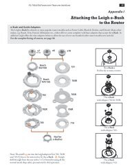
<strong>Guide</strong>bush Selection<br />
Only two sizes of guidebush are used with<br />
the <strong>Leigh</strong> M2. 7⁄16"[11,1mm] O.D. (outside<br />
diameter) <strong>and</strong> 5⁄8"[15,9mm] O.D.<br />
Use 7⁄ 16"[11,1mm] guidebush with<br />
5⁄16"[7,9mm] cutter.<br />
Use 5 ⁄ 8"[15,9mm] guidebush with<br />
1 ⁄2"[12.7mm] cutter.<br />
Here are the two types of <strong>Leigh</strong> guidebush<br />
<strong>and</strong> five <strong>Leigh</strong> adaptors. Use the chart on<br />
page 67 to select the adaptor <strong>and</strong>/or guidebush<br />
required for your router.<br />
CANADA<br />
A1-704<br />
A1-705<br />
706<br />
Adaptor No. 704<br />
Adaptor No. 705<br />
Adaptor No. 706<br />
65
66<br />
Appendix I M2 <strong>User</strong> <strong>Guide</strong><br />
<strong>Leigh</strong> 711 <strong>and</strong> 716 guidebushes fit directly<br />
to some routers using the screws that come<br />
with the router.<br />
<strong>Leigh</strong> 711TP <strong>and</strong> 716TP (TP st<strong>and</strong>s for<br />
Two Part) fit directly to Porter Cable <strong>and</strong><br />
most Black & Decker routers.<br />
<strong>Leigh</strong> universal adaptors fit to a wide range<br />
of plunge routers <strong>and</strong> accept one or both<br />
types of <strong>Leigh</strong> bush.<br />
GUIDEBUSH AND CUTTER SELECTION
Note: Ideal barrel depth is 1/4" to 9/32" (6mm to 7mm) below the router base. Other manufacturers’ guidebushes may require careful cutting to length.<br />
u<strong>Guide</strong>bush mounting screws are provided with adaptor <strong>and</strong> adaptor mounting screws are provided with router.<br />
t5/8"[15,9mm] O.D. guidebushes are used only with 1/2"[12,7mm] shank router bits. n MAFELL – Rework the adaptor slightly. 9 SCHEER – Rework the router base slightly.<br />
Check the make <strong>and</strong> model of your router in the left h<strong>and</strong> column. Where possible always order the <strong>Leigh</strong> adaptors<br />
<strong>and</strong> guidebushes (in red) which are specially designed for use on <strong>Leigh</strong> jigs. Other adaptors or guidebushes must be<br />
purchased from the manufacturer’s own distributor.<br />
ROUTER ROUTER LEIGH OR ROUTER 7/16" [11,1mm] METHOD OF<br />
MAKER MODEL MAKER’S ADAPTOR NO. OUTSIDE DIA. AT TACHMENT<br />
GUIDEBUSH NO.<br />
AEG OFE 710 in plunge base No adaptor required 711 Screws incl. w/router<br />
OFSE 2000 703 711 u<br />
ATLAS COPCO OFE 710 in plunge base, OFE 1000 No adaptor required 711 Screws incl. w/router<br />
OFSE 2000 703 711 u<br />
AXMINSTER AW635R No adaptor required 711 Screws incl. w/router<br />
WHITE AW127R Adapter supplied w/router 711 Screws incl. w/router<br />
All Professional, HD 1250, RP400K No adaptor required 711TP Threaded nut included<br />
BLACK & DECKER 6200 720673-00 711TP 2 screws req’d. 249412-20<br />
SR100, 7AEE, KW780 series No adaptor required 711 Screws incl. w/router<br />
90140, 90098, 90088 82855 Screws included<br />
90085, 90150, 90300, 90303, 90305, 91264 No adaptor required 82859 Screws included<br />
1600, 1601, 1602, 1603, 1604, 1606, B1350 2 610 906 290 711TP Threaded nut included<br />
BOSCH 1613,1613EVS,1613AEVS, 1614, 1614EVS, No adaptor required<br />
1617, 1617EVS, 1618EVS, 1619EVS, B1450, (RA1100 required RA1107 No screws required<br />
POF800ACE, GOF900ACE,GOF1300ACE, GOF2000CE for VGS)<br />
1611, 1611 EVS,1615,1615 EVS, B1550<br />
GOF1600, GOF1700ACE<br />
702 711 u<br />
CASALS FT750, FT 1000E, FT2000E 703 711 u<br />
CMT 1E 702R 711 u<br />
Set of 3 bushes from Sears USA order no.25082<br />
CRAFTSMAN All non-plunge models No adaptor required (stamped steel) or 25090 (plastic). Set of 3 Screws incl. w/set<br />
(SEARS) bushes from Sears Canada order no.092-970-704<br />
135275070 Plunge See Skill 1823 or 1835<br />
Other plunge models 702 711 u<br />
DW610 No adaptor required 711TP Threaded nut included<br />
DW613 No adaptor required 711 Screws incl. w/router<br />
DEWALT<br />
DW614, DW615, DW621<br />
DW624, DW625 <strong>and</strong> DW626<br />
North America Only<br />
Adaptor supplied w/router<br />
711TP Threaded nut included<br />
DW621K <strong>and</strong> DW626 outside N. America 706 711 u<br />
DW625 Type 1, 2 & 3 outside N. America 702 711 u<br />
DW625 Type 4 outside N. America, DW625EK 702R 711 u<br />
EINHELL EOF 850 SP, 0F-G 1100E No adaptor required 711 Screws incl. w/router<br />
OF15, OF15E, OF97, OF97E 706 711 u<br />
MOF68, MOF69, MOF96, MOF96E No adaptor required 711 Screws incl. w/router<br />
ELU MOF131, MOF177 Type 1, 2 & 3 702 711 u<br />
MOF177 Type 4, MOF177EK 702R 711 u<br />
2720, 2721, 3328 No adaptor required 711TP Threaded nut included<br />
3303, 3304 E09600 or 761 270-00 711TP Threaded nut included<br />
3337, 3338, 3339 702 711 u<br />
FEIN RT1800 Adapter supplied w/router 711TP u<br />
FESTOOL OF1E, OF2E, OF650, OF900E, OF1000, OF1010E 704 711TP Threaded nut included<br />
OF2000, OF2000E 705 711 u<br />
OF1400 with Festool Adaptor 711TP Threaded nut included<br />
FLEX All No adaptor required 711TP Threaded nut included<br />
FREUD FT2000 703 711 u<br />
HITACHI TR8, TR12, FM8, M8, M12 Series 703 711 u<br />
HOLZ-HER 2355, 2356 No adaptor required<br />
Screws incl. w/router<br />
2365 702 u<br />
ISKRA MR808A Series No adaptor required 711 Screws incl. w/router<br />
JEPSON 7412 703 711 u<br />
KANGO OF808 No adaptor required 711 Screws incl. w/router<br />
KRESS OF690 IE Series No adaptor required 711 Screws incl. w/router<br />
MAFELL LO65E 702 n 711 u<br />
3600,3606,3608,3612, 3612B, 3612BR<br />
703 711 u<br />
MAKITA 3612C N. America,3620, 3621<br />
3612C Europe Qk.Fit Base Contact your National <strong>Leigh</strong> distributor<br />
3601B 321 493-1 711TP Threaded nut included<br />
RP0910, RP1110C 706 711 u<br />
RF1100, RF1101, RD1100, RD1101, RP1101 No adaptor required 711TP Threaded nut included<br />
METABO OF1612, OFE1812 704 711TP Threaded nut included<br />
MILWAUKEE All No adaptor required 49-54-0520 Screws included<br />
PERLES OF808 Series, OFE 6990 No adaptor required 711 Screws incl. w/router<br />
PORTERCABLE(Rockwell) All No adaptor required 711TP Threaded nut included<br />
POWER DEVIL All No adaptor required 711 Screws incl. w/router<br />
R30, R50, R150, R151, RE155, R161<br />
703 711 u<br />
R500, R501, R502<br />
RYOBI R600, R601, RE600, RE601 702 711 u<br />
R160, R165, R170, R175, RE175, R180, R185 706 711 u<br />
SCHEER HM9, HM14, HM14-12, HM18, HM18-E No adaptor required 9 711 Screws incl. w/router<br />
SKIL 1823 or 1835 91803 711TP Threaded nut included<br />
All others No adaptor required 11592 Nut 11587<br />
STANLEY All See Bosch Distributor<br />
STAYER PR50 Series No adaptor required 711 Screws incl. w/router<br />
TREND (FELLISATI) T5 No adaptor required<br />
711 Screws incl. w/router<br />
T9 Adaptor supplied w/router<br />
WEGOMA OF850 Series No adaptor required 711 Screws incl. w/router<br />
711<br />
67
68<br />
Appendix I M2 <strong>User</strong> <strong>Guide</strong><br />
GUIDEBUSH AND CUTTER SELECTION
APPENDIX II<br />
Parts List
70<br />
Appendix II M2 <strong>User</strong> <strong>Guide</strong><br />
NOTE: When ordering parts, please quote the product model, serial<br />
number (on underside of fence scales), part number, part description<br />
<strong>and</strong> quantity required.<br />
PART NO. QUANTITY DESCRIPTION<br />
31 1 M2 <strong>User</strong>’s <strong>Guide</strong><br />
180 1 1 ⁄2" [12,7mm] Spiral Upcut Bit, HSS<br />
441 1 <strong>Guide</strong> Rail<br />
451 1 Finger <strong>Guide</strong> Rail<br />
480 10 Right H<strong>and</strong> Finger Bevel Nut<br />
490 10 Left H<strong>and</strong> Finger Bevel Nut<br />
500 20 Finger Lock Screws<br />
600 10 Right H<strong>and</strong> Finger c/w Bevel Nut <strong>and</strong> Screw<br />
610 10 Left H<strong>and</strong> Finger c/w Bevel Nut <strong>and</strong> Screw<br />
620 1 Right H<strong>and</strong> Support Bracket<br />
630 1 Left H<strong>and</strong> Support Bracket<br />
641M 1 Millimetre Right H<strong>and</strong> Finger Scale Assembly, complete<br />
641 1 Inch Right H<strong>and</strong> Finger Scale Assembly, complete<br />
651M 1 Millimetre Left H<strong>and</strong> Finger Scale Assembly, complete<br />
651 1 Inch Left H<strong>and</strong> Finger Scale Assembly, complete<br />
660 4 Scale Lock Screws<br />
671 1 Right H<strong>and</strong> Fence Scale, complete<br />
681 1 Left H<strong>and</strong> Fence Scale,complete<br />
690 1 Fence Assembly c/w Alloy Plugs<br />
695 2 Side Stop Extensions<br />
PARTS LIST
651<br />
651 M<br />
660<br />
681<br />
630<br />
610<br />
490<br />
31<br />
500<br />
695<br />
441<br />
451<br />
600 480<br />
690<br />
180<br />
641<br />
641M<br />
671<br />
620<br />
71
72<br />
Appendix II M2 <strong>User</strong> <strong>Guide</strong><br />
PARTS LIST
APPENDIX III<br />
Customer Support
74<br />
Appendix III M2 <strong>User</strong> <strong>Guide</strong><br />
Our Commitment to You<br />
At <strong>Leigh</strong> Industries we take pride in our commitment<br />
to provide excellence in customer service <strong>and</strong> support.<br />
We hope your use of the <strong>Leigh</strong> jig will be enjoyable,<br />
rewarding <strong>and</strong> most of all, trouble free, <strong>and</strong> that this<br />
<strong>User</strong> <strong>Guide</strong> will provide you with the answers to any<br />
<strong>Leigh</strong> Industries Ltd. (EST. 1981)<br />
P.O. Box 357,<br />
1615 Industrial Ave.,<br />
Port Coquitlam, B.C.,<br />
Canada, V3C 4K6<br />
Australia & New Zeal<strong>and</strong><br />
Carba-Tec Pty. Ltd.<br />
40 Harries Rd, Coorparoo, Qld.,<br />
4151<br />
Phone (07) 3397 2577<br />
Fax: (07) 3397 2785<br />
Ordering: 180 658 111<br />
email: orders@carbatec.com.au<br />
Mik International<br />
Post: Box 70 Burnside SA 5066<br />
Australia<br />
Store: 27 Magill Road, Stepney, SA<br />
5069 Australia<br />
Tel: +61 8 8363 4666<br />
Fax: +61 8 8362 3444<br />
Email: inquiries@mik.com.au<br />
Web: www.mik.com.au<br />
France<br />
Ets Bordet<br />
23 Rue Traversiere<br />
93556 Montreuil Cedex<br />
France<br />
Phone: 01 48 58 28 39<br />
Fax: 01 48 58 48 58<br />
Email: info@bordet.fr<br />
Web: http://www.bordet.fr/<br />
pages/<br />
Germany, Austria & Switzerl<strong>and</strong><br />
Hacker GMBH<br />
Holzbearbeitungsmaschinen<br />
Traberhofstraße 103<br />
D-83026 Rosenheim<br />
Deutschl<strong>and</strong><br />
Tel: 08031 269650<br />
Fax: 08031 68221<br />
Web: www.leigh.de<br />
Canada & USA - Manufacturer<br />
Italy<br />
Ferrari Macchine Legno S.R.L.<br />
Via Gallarate, 74-7820019 Settimo<br />
Milanese (MI), Italy<br />
Tel: +39 02 33501095<br />
Fax: +39 02 33500527<br />
Email: info@ferrarimacchine.com<br />
Web: www.ferrarimacchine.com<br />
South Africa<br />
Hardware Centre<br />
Post: PO Box 4059, R<strong>and</strong>burg,<br />
2125, South Africa<br />
Store: Shop 8 Homeworld Centre<br />
Cnr Hans Strijdom & C.R Swart Drives,<br />
R<strong>and</strong>burg, Johannesburg<br />
Tel: (011) 791-0844/46<br />
Fax: (011) 791-0850<br />
Email: info@hardwarecentre.co.za<br />
Web: www. hardwarecentre.co.za<br />
Sweden<br />
Toolbox Sweden AB<br />
Horla Heden 1<br />
SE 441 93 Alingsås, Sweden<br />
Tel: 0322-67 04 40<br />
Fax: 0322-67 04 49<br />
Email: info@toolbox.se<br />
Web: www.toolbox.se<br />
United Kingdom & Eire<br />
BriMarc Associates Limited<br />
Nick Lowe House<br />
Unit 20A Harriott Drive<br />
Heathcote Industrial Estate<br />
Warwick CV34 6TJ, Engl<strong>and</strong><br />
Tel: 0845 330 9100<br />
Tel: +44(0)1926 884440 (Intl.)<br />
Fax: 01926 884444<br />
Web: www.brimarc.com<br />
CUSTOMER SUPPORT<br />
questions you may have.<br />
If this is not the case, please feel free to contact our<br />
technical support staff or our distributor in your country<br />
by any of the means listed below.<br />
Toll Free: 1-800-663-8932<br />
Telephone: (604) 464-2700<br />
Facsimile: (604) 464-7404<br />
*E-mail: leigh@leighjigs.com<br />
Website: www.leighjigs.com<br />
*Email can be useful, but technical queries usually raise queries from us. So the telephone (if possible) is a much<br />
quicker <strong>and</strong> more convenient way to get those queries answered; either directly to <strong>Leigh</strong> (toll-free in North<br />
America) or to your national distributor. …Thanks!<br />
Distributors<br />
Japan<br />
Off Corporation Inc.<br />
323-1 Shimizu-Yanbara<br />
Shizuoka City, Japan 424-0002<br />
Tel: 81-543-67-6511<br />
Fax: 81-543-67-6515<br />
Email: craft@off.co.jp<br />
Web: www.off.co.jp<br />
Korea<br />
<strong>Leigh</strong> Korea (Woodworking Academy)<br />
#102, Kyunggi Praza, 36-5, NeungPyung-<br />
Ri<br />
Opo-Eup, Kwngju-Si, Kyunggi-do,<br />
Korea<br />
Tel: +82-(0)31-768-3303<br />
Fax: +82-(0)31-768-3376<br />
Email: smgi@paran.com<br />
Web:www.woodworkingacademy.<br />
com<br />
Norway<br />
Aurus Stoelsmyrvn. 103<br />
5542 Karmsund<br />
Norway<br />
Tel: +47 992 71 932<br />
Email: info@aurus.no<br />
Website: www.aurus.no<br />
© 1990 <strong>Leigh</strong> Industries Ltd. All rights reserved.<br />
No part of this publication may be reproduced,<br />
stored in a retrieval system, or transmitted in any<br />
form or by any means, electronic, mechanical,<br />
recording, or otherwise, without the prior written<br />
permission of <strong>Leigh</strong> Industries Ltd. 9/07<br />
Joining Tradition with Today